soil investigation by aurangzeb
TRANSCRIPT

1

Student civil ENGNR: AURANGZEB SITE
INVESTIGATION
00923459026940
2
3
SITE INVESTIGATION
Determination of surface and subsurface soil conditions and features in an area of proposed construction that may influence the design and
construction and address expected post construction problems.
SCOPE OF INVESTIGATION
Simple visual examination of soil at the surface or from shallow test pits.Detailed study of soil and groundwater to a reasonable depth (influence zone) by
sampling from bore holes, shafts and adits and in-situ and laboratory .

4
COMMON STAGES IN SITE
INVESTIGATIONS: Desk Study Site Reconnaissance Field Investigationsa) Preliminary Ground Investigationb) Detailed Ground Investigation Laboratory Testing Report Writing Follow up Investigations during design & constructionAppraisal of performance

5
DESK STUDY:
The collection of information already available about a site in
existing records.
The information required from desk study are
General Land Survey:

6
Local Authority Bye-Laws:
Ground Conditions:
Sources of Material:

7
Water Supply:
Electricity, Gas and Telephone:

8
Sources of information for desk study
Ordnance survey (Survey of Pakistan)
Geological survey and soil surveys maps and memoirs (Geological Survey of Pakistan)
Hydrographic department
Meteorological Department
Seismological Department
Aerial Photograph
9
SITE RECONNAISSANCE:
points of worth consideration
A. Preparation for Visit:
A visit to the site by experts traversing the whole area, preferably on foot and picking up relevant technical information by a thorough visual examination

10
B. Site and Ground Information:
11
C. Subsurface Information:
Neighboring quarries, cuttings and escarpment should be carefully inspected which may reveal soil and rock types and their mass characteristics e.g., the orientation, frequency, and character of bedding and jointing discontinuities and weathering profiles.
12
FIELD INVESTIGATION:Preliminary Ground Investigation:
Few bores or test pits are made to know the subsoil, stratification, index and strength properties and the location of GWT.
SIGNIFICANCE : For small projects this step may be final and sufficient to establish foundation
criteria. For large extended sites, this step may be necessary for best planning for
detailed investigation.
Detailed Ground Investigation:
Carried out for large projects or where the soil is of poor quality and/or non uniform soil.
it verifies and expand information previously collected.
13
Type of Ground Investigation
For new works.
For safety of existing works due to proposed extension/alternation or new works in the near vicinity.
For failure of existing works.
For material survey for constructional purposes.
14
Scope of ground investigation
Points of guidance in planning the ground investigation
The nature and variability of the ground and groundwater.
The type of project
The reliability
15
2. The type of project
The scope will depend on the importance, cost of the project and the risk of life or property involved in cases of failure.
For important projects and where risk of life is involved scope of work may be greater.
3. The reliability
For higher reliability of the investigation data, detailed information about the site and strata through a bigger scope of work are required
16
LABORATORY TESTING
This stage will include tests on representative disturbed and good quality undisturbed samples
For classification, shear strength, compressibility, permeability and chemical analysis of soil/rock and groundwater.
For construction material, the tests, such as compaction, California bearing ratio, classification, strength, chemical and petrographic analyses will be required.
17
REPORT WRITING
The contents of a site investigation report shall include the following with relevant details for each one.
a. Introduction
This includes
• The name of the client• The site investigation • The consultant firms• The nature and purpose of investigation• The name of project • The time over which the work was carried out
18
b. Scope of work
This includes Details of
field and laboratory activities
c. Description of methods
This includes a brief account of boring/drilling,sampling testing methodsA note should be made of any difficulties experienced during work together with weather conditions.
19
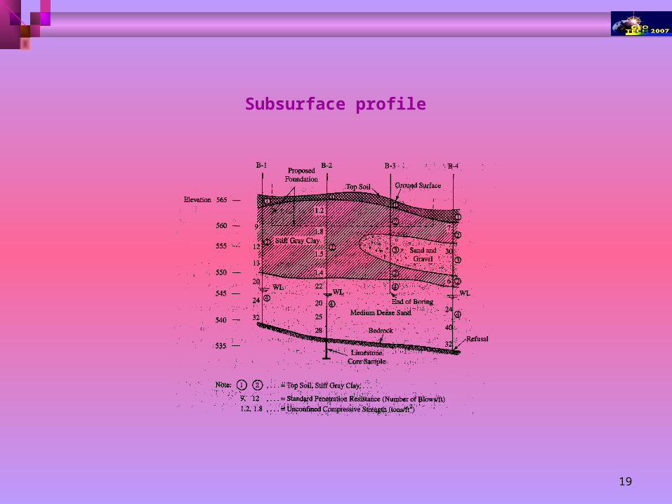
Subsurface profile
20
Shallow groundwater table
Some of the geotechnical problems that may arise are:
i. Foundation dewatering, which may require design of proper dewatering system.
ii. Heaving or eventual boiling of the base of excavation due to dewatering.
iii. Disposal of water away from the site.
iv. Necessity of sheeting and bracing to support the excavations which may collapse due to seepage from walls of cuttings.
v. Development of high pore water or uplift pressures.
vi. Necessity for foundation treatment.
vii. Lowering of water table which may be short term i.e., only for laying foundations or long term.
viii. Attention will also have to be paid to the problems related to future water table fluctuation.
ix. Use of special materials in case groundwater contains harmful chemicals.
21
The type of ground:
The associated problems related to the soil type will be quite diversified.
i. For foundations in clayey soil, consolidation settlement (total or life time) will require consideration and rise of ground water table will cause significance loss of shear strength while cause serious variation in shear strength (from stiff to soft) and shrinkage problems.
ii. For foundation in sandy soil, stability of excavation and loosening or collapse of bore holes for piles will have to be considered while for embankment in sandy soil to maintain uniform strength lateral movement will have to be controlled.
iii. For rocks, weathering, dip and strike of bedding plane, frequency of jointing, nature of filler etc. may cause bearing or settlement problems for foundations and stability problems for slopes.
iv. Problems associated with non-uniformity of the deposit, stratification, pockets of undesirable materials, etc., are worth discussion
v. Variation in consistency or relative density even for uniform ground conditions may develop settlement problems.

22
Recommendations
Recommendation should be made according to the nature of the project to provide sufficient and clear information to the designer for design of foundations and to the contractor for planning construction techniques and equipment.
23
METHODS OF INVESTIGATION
24
METHODS OF INVESTIGATION
The methods to determine the sequence, thickness and lateral extent of the soil strata and, where appropriate the level of
bedrock.
The common methods include
Test pits
Shafts and adits
Boring or drilling
25
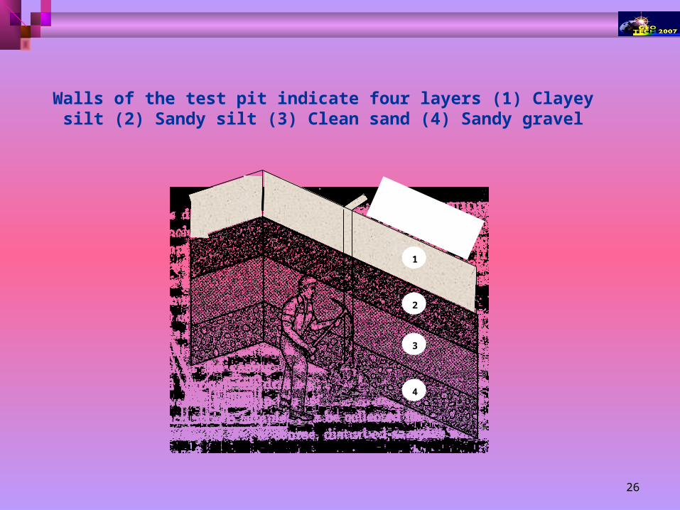
Test Pits
The excavation of test pits is a simple and reliable method.
The depth is limited to 4-5m only.
The in-situ conditions are examined visually
It is easy to obtain disturbed and undisturbed samples
Block samples can be cut by hand tools and tube samples can be taken from the bottom of the pit.
26
1
2
3
4
Walls of the test pit indicate four layers (1) Clayey silt (2) Sandy silt (3) Clean sand (4) Sandy gravel
27
Shafts and Adits
Shafts or deep pits and adits or headings are very costly and their use is justified only in investigations for large projects, such as dams, if the ground conditions could not be ascertained adequately by other means.
Shafts or headings are not usually excavated below the groundwater table.
Shafts are usually advanced by hand excavation, the sides being supported by timbering.
Headings or adits are excavated laterally from the bottom of shafts or from the surface into hillsides, both the sides and roof being supported.
28
Boring or Drilling
Boring refers to advancing a hole in the ground. Boring is required for the following:
To obtain representative soil and rock samples for laboratory tests.
To identify the groundwater conditions.
Performance of in-situ tests to assess appropriate soil characteristics.
Some of the common types of boring are as followsAuger boring
Wash boring
Percussion boring
Rotary drilling
29
Auger Boring
Hand Auger It is the simplest method of boring used for small projects in soft cohesive soils.
For hard soil and soil containing gravels boring with hand auger becomes difficult. Hand-augered holes can be made upto about 20m depth, although depth greater than about 8-10m is
usually not practical.
The length of the auger blade varies from 0.3-0.5m.
The auger is rotated until it is full of soil, then it is withdrawn to remove the soil and the soil type present at various depths is noted.
Repeated withdrawl of auger for soil removal makes boring difficult below 8-10m depth.
The soil samples collected in this manner are disturbed samples and can be used for classification test. Auger boring may not be possible in very soft clay or coarse sand because the hole tends to collapse when auger is removed
Hand Auger Mechanical Auger
30
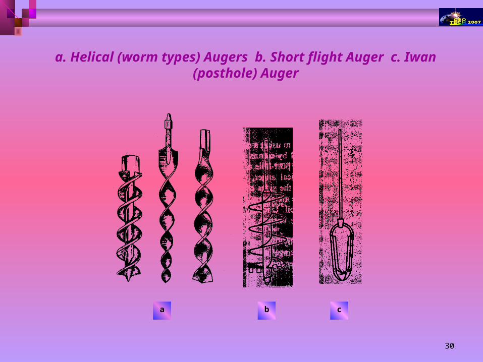
a. Helical (worm types) Augers b. Short flight Auger c. Iwan (posthole) Auger
a b c
31
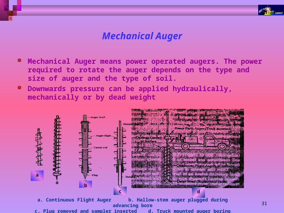
Mechanical Auger
Mechanical Auger means power operated augers. The power required to rotate the auger depends on the type and size of auger and the type of soil.
Downwards pressure can be applied hydraulically, mechanically or by dead weight
a
ab
c d
a. Continuous Flight Auger b. Hallow-stem auger plugged during advancing borec. Plug removed and sampler inserted d. Truck mounted auger boring machine
32
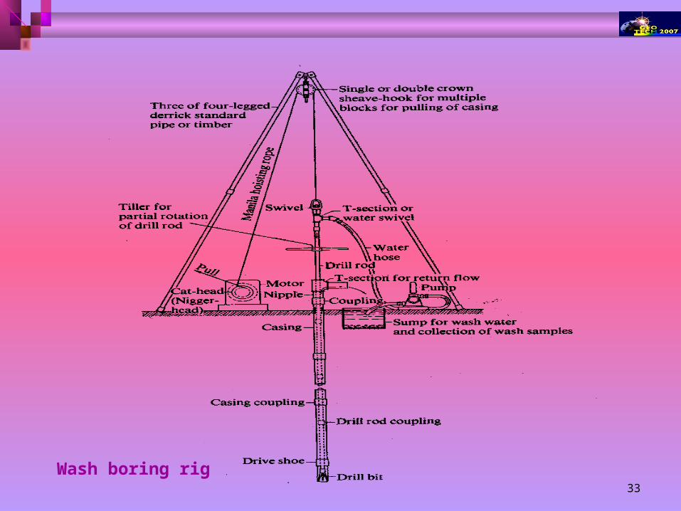
Wash boring Water with high pressure pumped through hallow boring rods is released from narrow holes in
a chisel attach to the lower end of the rods.
The soil is loosened and broken by the water jet and the up-down moment of the chisel.
The soil particles are carried in suspension to the surface between the rock and the borehole sites.
The rods are raised and drop for chopping action of the chisel by means of winch. Wash boring can be used in most type of soil but the progress is slow in coarse gravel strata.
The accurate identification of soil strata is difficult due to mixing of the material has they are carried to the surface.
The method is unacceptable for obtaining soil samples.
It is only used for advancing the borehole to enable tube sample to be taken are field test to be carried at the hole bottom.
The advantage is that the soil immediately below the hole remains relatively un-disturbed
33
Wash boring rig
34
ROTARY DRILLING
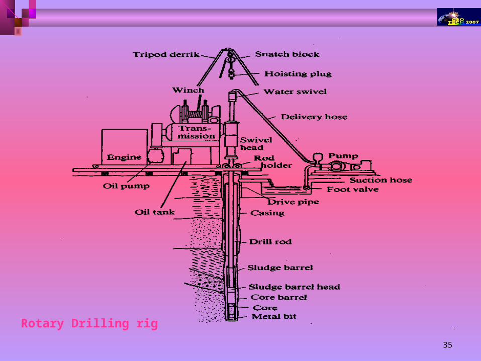
The rig consists of a derrick, power unit, winch, pump and a drill head to apply high-speed rotary drive and downward thrust to the drilling rods.
Primarily intended for investigation in rock, but also used in soils.
The drilling tool, (cutting bit or a coring bit) is attached to the lower end of hollow drilling rods
The coring bit is fixed to the lower end of a core
Water or drilling fluid is pumped down the hollow rods and passes under pressure through narrow holes in the bit or barrel
The drilling fluid cools and lubricates the drilling tool and carries the loose debris to the surface between the rods and the side of the hole.
The fluid (bentonite slurry) also provides some support to the sides of the hole if no casing is used. There are two forms of rotary drilling, open-hole drilling and core drilling.
Open- hole drilling, which is generally used in soils and weak rock, just for advancing the hole
The drilling rods can then be removed to allow tube samples to be taken or in-situ tests to be carried out. In core drilling, which is used in rocks and hard clays, the diamond or tungsten carbide bit cuts an annular
hole in the material and an intact core enters the barrel, to be removed as a sample. Typical core diameters are 41, 54 and 76mm, but can range up to 165 mm.
35
Rotary Drilling rig
36
PERCUSSION BORING
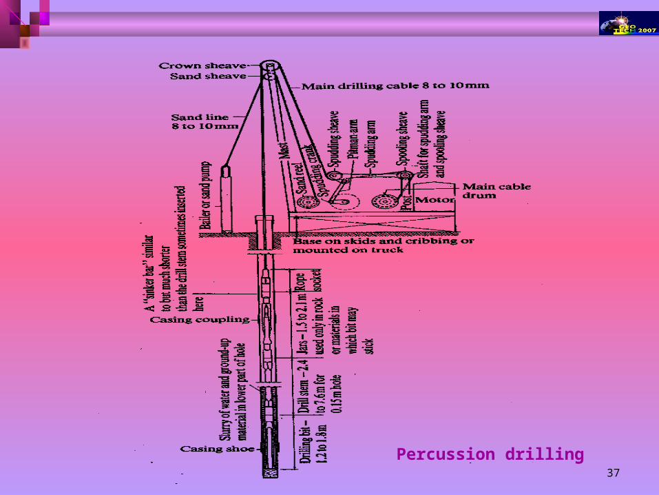
Percussion boring can be employed in most types of soil, including those containing cobbles and boulders.
The boring rig consists of a derrick, a power unit and a winch carrying a light steel cable, which passes through a pulley on top of the derrick.
The borehole is advanced by the percussive action of the shell (or bailer) and the clay cutter, which is alternately raised and dropped (usually over a distance of I-2m) by means of the winch unit. If necessary a heavy weight called a sinker bar can be attached to the bailer to increase the impact energy.
The shell, which is used in sands and other coarse soils, is a heavy steel tube fitted with a flap or clack valve at the lower end.
Below the water table the percussive action of the shell loosens the soil and produces a slurry in the borehole. Above the water table a slurry is produced by introducing water into the borehole.
The slurry passes through the clack valve during the downward movement of the shell and is retained by the valve during the upward movement. When full, the shell is raised to the surface to be emptied.
37
Percussion drilling
38
GROUNDWATER OBSERVATIONS
AN IMPORTANT PART OF ANY GROUND INVESTIGATION FOR DEEP EXCAVATIONS IS THE DETERMINATION OF
water table level and of any artesian pressure in particular strata. The variation of level or pressure over a given period of time.
Water table level can be determined
by measuring the depth to the water surface in a borehole.
Precautions Measurements should be taken at regular intervals until the water level becomes constant
Because Water levels in boreholes may take a considerable time to stabilize; this time, known as the response time, depends on the permeability of the soil.
It is preferable that the level should be determined as soon as the borehole has reached water table level. If the borehole is further advanced it may penetrate a stratum under artesian pressure, resulting in the water level in the hole being above water table level
39
A stratum of low permeability below a perched water table should not be penetrated before the water level has been established.
If a perched water table exists, the borehole must be cased in order that the main water table level is correctly determined:
if the perched aquifer is not sealed, the water level in the borehole will be above the main water table level.
When it is required to determine the pore water pressure in a particular stratum, a piezometer (Section) should be used.
The simplest type is the open standpipe piezometer with the porous element sealed at the appropriate depth.
In soils of low permeability hydraulic piezometer having a relatively short response time.
Groundwater samples required for chemical analysis to determine sulphates (which may attack Portland cement concrete) or other corrosive constituents.
Samples must not contaminated or diluted. A sample should be taken immediately the water-bearing stratum is reached in boring. It is preferable to obtain samples from the standpipe piezometers if these have been installed.