software and programming manual
TRANSCRIPT
SD750
SOFTWARE AND
PROGRAMMING MANUAL
LOW VOLTAGE VARIABLE SPEED DRIVE

Software and Programming Manual
Edition: August 2021
SD75SW01MI Rev. M

SD750 POWER ELECTRONICS
2 ABOUT THIS MANUAL
ABOUT THIS MANUAL
PURPOSE
This manual contains important instructions for the installation and maintenance of Power Electronics
SD750 variable speed drives.
TARGET AUDIENCE
This manual is intended for qualified customers who will install, operate and maintain Power Electronics
SD750 variable speed drives.
Only trained electricians may install and commission the drives.
REFERENCE MANUALS
The following reference documents are available for SD750 variable speed drives:
• Hardware and Installation Manual SD750.
• Programming and Software Manual SD750.
• Pumps Application Manual.
• Accessories Manuals.
POWER ELECTRONICS CONTACT INFORMATION
Power Electronics USA Inc.
1510 N. Hobson Street, Gilbert,
Phoenix
AZ 85233
UNITED STATES OF AMERICA
US Sales: 602-354-4890 / (480) 519-5977
Power Electronics España, S.L.
Polígono Industrial Carrases
Ronda del Camp d’Aviació nº 4
46160, Llíria (Valencia)
SPAIN
Telephone: (+34) 96 136 65 57
Website: www.power-electronics.com
POWER ELECTRONICS SD750
REVISIONS CONTROL 3
EN
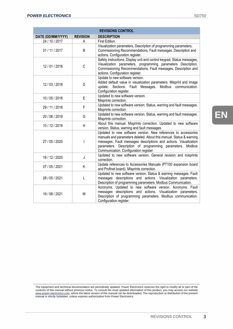
REVISIONS CONTROL
DATE (DD/MM/YYYY) REVISION DESCRIPTION
24 / 10 / 2017 A First Edition.
21 / 11 / 2017 B Visualization parameters, Description of programming parameters, Commissioning Recommendations, Fault messages. Description and actions. Configuration register.
12 / 01 / 2018 C
Safety instructions, Display unit and control keypad, Status messages, Visualization parameters, programming parameters Description, Commissioning Recommendations, Fault messages. Description and actions. Configuration register.
12 / 03 / 2018 D
Update to new software version. Added default value in visualization parameters. Misprint and image update. Sections: Fault Messages. Modbus communication. Configuration register.
10 / 05 / 2018 E Updated to new software version. Misprints correction.
29 / 11 / 2018 F Updated to new software version. Status, warning and fault messages. Misprints correction.
20 / 06 / 2019 G Updated to new software version. Status, warning and fault messages. Misprints correction.
10 / 12 / 2019 H About this manual. Misprints correction. Updated to new software version. Status, warning and fault messages.
27 / 05 / 2020 I
Updated to new software version. New references to accessories manuals and parameters deleted. About this manual. Status & warning messages. Fault messages descriptions and actions. Visualization parameters. Description of programming parameters. Modbus Communication. Configuration register.
18 / 12 / 2020 J Updated to new software version. General revision and misprints correction.
07 / 05 / 2021 K Update references to Accessories Manuals (PT100 expansion board and Profinet board). Misprints correction.
28 / 05 / 2021 L Updated to new software version. Status & warning messages. Fault messages descriptions and actions. Visualization parameters. Description of programming parameters. Modbus Communication.
19 / 08 / 2021 M
Acronyms. Updated to new software version. Acronyms. Fault messages descriptions and actions. Visualization parameters. Description of programming parameters. Modbus communication. Configuration register.
The equipment and technical documentation are periodically updated. Power Electronics reserves the right to modify all or part of the contents of this manual without previous notice. To consult the most updated information of this product, you may access our website www.power-electronics.com, where the latest version of this manual can be downloaded. The reproduction or distribution of the present manual is strictly forbidden, unless express authorization from Power Electronics.
SD750 POWER ELECTRONICS
4 TABLE OF CONTENTS
TABLE OF CONTENTS
ABOUT THIS MANUAL ............................................................................................................................... 2
ACRONYMS ................................................................................................................................................. 7
SAFETY SYMBOLS ..................................................................................................................................... 9
SAFETY INSTRUCTIONS .......................................................................................................................... 10
1. DISPLAY UNIT AND CONTROL KEYPAD ......................................................................................... 11 Keypad unit description ...................................................................................................................... 11
LED for status indication .................................................................................................................. 12 Alphanumeric LCD display .............................................................................................................. 12 Control keys ..................................................................................................................................... 12
Menu .................................................................................................................................................. 13
2. STATUS & WARNING MESSAGES ..................................................................................................... 15 List of status messages ...................................................................................................................... 15 List of warning messages ................................................................................................................... 16
3. FAULT MESSAGES. DESCRIPTIONS AND ACTIONS ...................................................................... 18 Description of fault list ........................................................................................................................ 19 Troubleshooting .................................................................................................................................. 23
4. VISUALIZATION PARAMETERS ......................................................................................................... 29 Group V1: Motor visualization ............................................................................................................ 30 Group V2: Drive visualization ............................................................................................................. 31 Group V3: External visualization......................................................................................................... 31 Group V4: Internal visualization .......................................................................................................... 32 Group V5: Programmable parameters ................................................................................................ 32 Group V6: Registers ........................................................................................................................... 33 Group V7: Rectifier info ...................................................................................................................... 33 Group V8: Date and time .................................................................................................................... 33 Group V9: Last fault registers ............................................................................................................. 34
Subgroup V9.1: Motor registers ....................................................................................................... 34 Subgroup V9.2: Drive registers ........................................................................................................ 34 Subgroup V9.3: External registers ................................................................................................... 35 Subgroup V9.4: Internal registers .................................................................................................... 35 Subgroup V9.6: Local motor reg ...................................................................................................... 36
Group V11: Exp PT100 ...................................................................................................................... 36 Group V12: Warning history ............................................................................................................... 36 Group V13: Local Motor vis ................................................................................................................ 37
5. DESCRIPTION OF PROGRAMMING PARAMETERS ......................................................................... 38 Group 1: Options ................................................................................................................................ 39 Group 2: Motor nameplate data .......................................................................................................... 40 Group 3: References .......................................................................................................................... 41 Group 4: Inputs ................................................................................................................................... 42
POWER ELECTRONICS SD750
TABLE OF CONTENTS 5
EN
Subgroup 4.1: Digital inputs ............................................................................................................. 42 Subgroup 4.2: Analogue input 1 ...................................................................................................... 46 Subgroup 4.3: Analogue input 2 / pulse ........................................................................................... 48 Subgroup 4.4: Analogue input 3 / PT100 ......................................................................................... 50 Subgroup 4.5: Analogue input 4 ...................................................................................................... 51 Subgroup 4.6: Analogue input 5 ...................................................................................................... 51 Subgroup 4.7: Analogue input 6 ...................................................................................................... 51 Subgroup 4.8: Analogue input 7 ...................................................................................................... 51
Group 5: Acc / Dec rates .................................................................................................................... 52 Subgroup 5.1: Acceleration ............................................................................................................. 52 Subgroup 5.2: Deceleration ............................................................................................................. 52 Subgroup 5.3: Motorized potentiometer ........................................................................................... 52 Others ............................................................................................................................................. 53
Group 6: PID Control .......................................................................................................................... 53 Group 7: Start / stop control ............................................................................................................... 54
Subgroup 7.1: Start .......................................................................................................................... 54 Subgroup 7.2: Stop .......................................................................................................................... 55 Subgroup 7.3: Spin start .................................................................................................................. 56
Group 8: Outputs ................................................................................................................................ 56 Subgroup 8.1: Digital outputs .......................................................................................................... 56 Subgroup 8.2: Analogue output 1 .................................................................................................... 61 Subgroup 8.3: Analogue output 2 / pulse ......................................................................................... 62 Subgroup 8.4: Analogue output 3 .................................................................................................... 62 Subgroup 8.5: Analogue output 4 .................................................................................................... 62 Subgroup 8.6: Analogue output 5 .................................................................................................... 63 Subgroup 8.7: Analogue output 6 .................................................................................................... 63
Group 9: Comparators ........................................................................................................................ 64 Subgroup 9.1: Comparator 1 ........................................................................................................... 64 Subgroup 9.2: Comparator 2 ........................................................................................................... 65 Subgroup 9.3: Comparator 3 ........................................................................................................... 66
Group 10: Limits ................................................................................................................................. 67 Subgroup 10.1: Speed ..................................................................................................................... 67 Subgroup 10.2: Current/Torque ....................................................................................................... 67
Group 11: Protections ......................................................................................................................... 68 Subgroup 11.1: Input ....................................................................................................................... 68 Subgroup 11.2: Motor ...................................................................................................................... 69
Group 12: Auto reset .......................................................................................................................... 70 Group 13: Fault history ....................................................................................................................... 71 Group 14: Multi-references ................................................................................................................. 71 Group 15: Inch speeds ....................................................................................................................... 72 Group 16: Skip frequencies ................................................................................................................ 72 Group 17: Brake ................................................................................................................................. 73 Group 18: Encoder ............................................................................................................................. 73 Group 19: Fine tuning ......................................................................................................................... 74
Subgroup 19.1: IGBT control ........................................................................................................... 74 Subgroup 19.2: Motor load .............................................................................................................. 75 Subgroup 19.3: Motor model ........................................................................................................... 76 Subgroup 19.4: Vector PID .............................................................................................................. 76
Group 20: Serial Communication........................................................................................................ 77 Subgroup 20.1: Modbus RTU .......................................................................................................... 77 Subgroup 20.2: Profibus configuration ............................................................................................. 78 Subgroup 20.6: Custom modbus configuration ................................................................................ 78
SD750 POWER ELECTRONICS
6 TABLE OF CONTENTS
Subgroup 20.7: Custom modbus values .......................................................................................... 79 Group 21: Networks ............................................................................................................................ 80
Subgroup 21.1: Ethernet .................................................................................................................. 80 Subgroup 21.2: Client TCP .............................................................................................................. 80 Subgroup 21.3: EtherNet / IP ........................................................................................................... 80 Subgroup 21.4: Profinet ................................................................................................................... 80
Group 23: Expansion .......................................................................................................................... 81 Subgroup 23.1: PT100 ..................................................................................................................... 81 Subgroup 23.2: Input/output ............................................................................................................ 81 Subgroup 23.3: Communications..................................................................................................... 81 Others ............................................................................................................................................. 82
Group 25: Master / Slave .................................................................................................................... 82 Group 26: Fans................................................................................................................................... 82
6. MODBUS COMMUNICATION .............................................................................................................. 83 Supported Modbus Function Codes ................................................................................................... 83
Modbus function code Nº 3: Registers reading ................................................................................ 83 Modbus Function Code Nº 16: Registers Writing ............................................................................. 84
Addressing modes .............................................................................................................................. 85 Broadcast addressing mode ............................................................................................................ 85
Remote control functions .................................................................................................................... 85 Summary of modbus addresses ......................................................................................................... 86
Modbus register ‘COMMS STATUS’ ................................................................................................ 86 Programming parameters ................................................................................................................... 87 Visualization parameters .................................................................................................................. 102
7. COMMON CONFIGURATIONS ......................................................................................................... 109 Start / Stop commands and speed reference by keypad .................................................................. 109
Parameter configuration ................................................................................................................ 109 Start / Stop commands by terminals and speed reference by analogue input .................................. 110
Parameter configuration ................................................................................................................ 110 Connection drawing ....................................................................................................................... 111
Start / Stop commands by terminals and speed reference by motorized potentiometer ................... 112 Parameter configuration ................................................................................................................ 112 Connection drawing ....................................................................................................................... 113
Start / Stop commands by terminals and seven speed references selectable by digital inputs ........ 114 Parameter configuration ................................................................................................................ 114 Connection drawing ....................................................................................................................... 115
8. CONFIGURATION REGISTER .......................................................................................................... 116
POWER ELECTRONICS SD750
ACRONYMS 7
EN
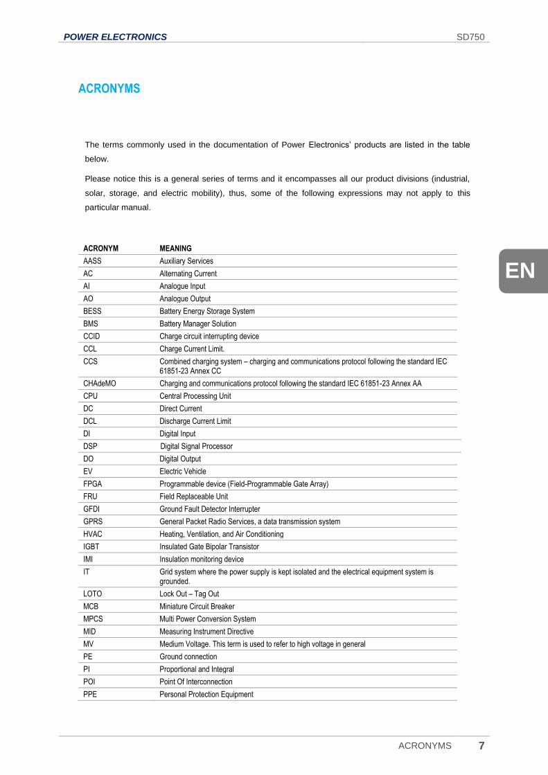
ACRONYMS
The terms commonly used in the documentation of Power Electronics’ products are listed in the table
below.
Please notice this is a general series of terms and it encompasses all our product divisions (industrial,
solar, storage, and electric mobility), thus, some of the following expressions may not apply to this
particular manual.
ACRONYM MEANING
AASS Auxiliary Services
AC Alternating Current
AI Analogue Input
AO Analogue Output
BESS Battery Energy Storage System
BMS Battery Manager Solution
CCID Charge circuit interrupting device
CCL Charge Current Limit.
CCS Combined charging system – charging and communications protocol following the standard IEC 61851-23 Annex CC
CHAdeMO Charging and communications protocol following the standard IEC 61851-23 Annex AA
CPU Central Processing Unit
DC Direct Current
DCL Discharge Current Limit
DI Digital Input
DSP Digital Signal Processor
DO Digital Output
EV Electric Vehicle
FPGA Programmable device (Field-Programmable Gate Array)
FRU Field Replaceable Unit
GFDI Ground Fault Detector Interrupter
GPRS General Packet Radio Services, a data transmission system
HVAC Heating, Ventilation, and Air Conditioning
IGBT Insulated Gate Bipolar Transistor
IMI Insulation monitoring device
IT Grid system where the power supply is kept isolated and the electrical equipment system is grounded.
LOTO Lock Out – Tag Out
MCB Miniature Circuit Breaker
MPCS Multi Power Conversion System
MID Measuring Instrument Directive
MV Medium Voltage. This term is used to refer to high voltage in general
PE Ground connection
PI Proportional and Integral
POI Point Of Interconnection
PPE Personal Protection Equipment
SD750 POWER ELECTRONICS
8 ACRONYMS
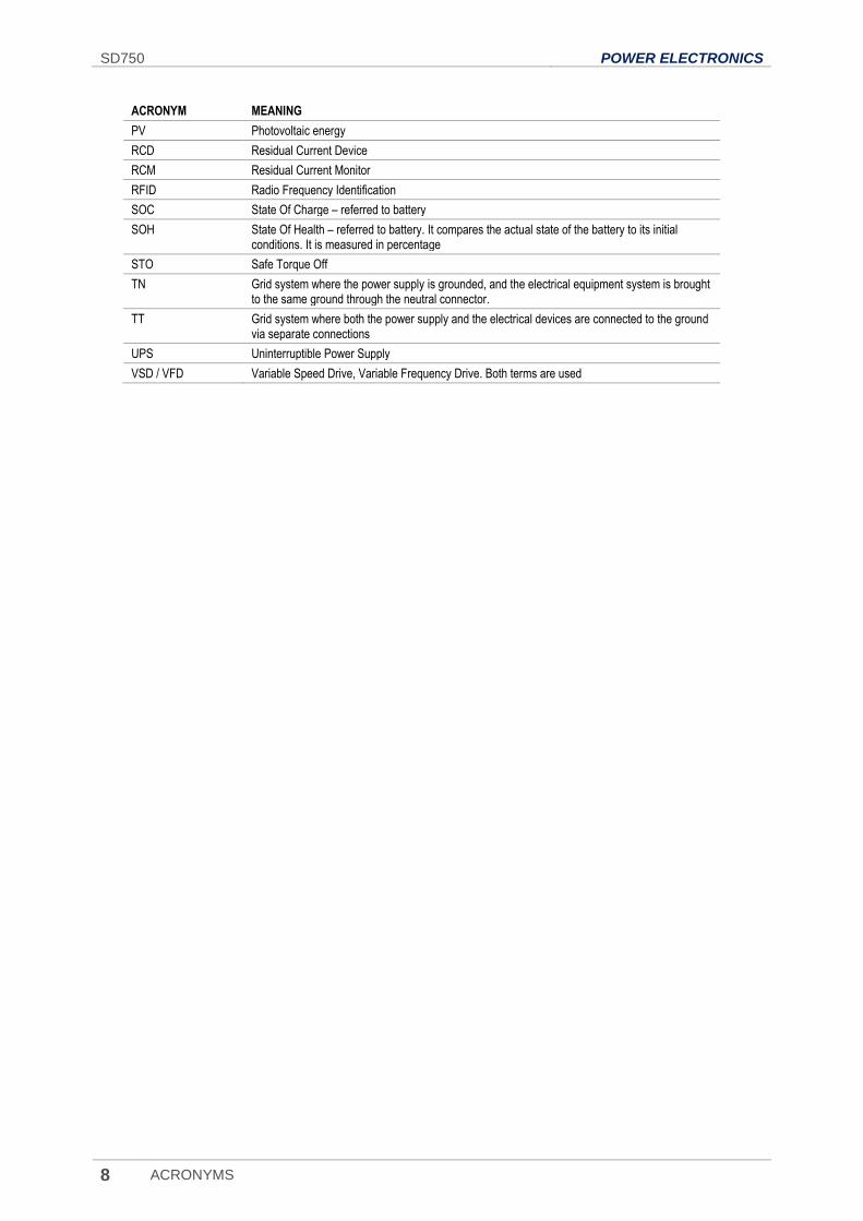
ACRONYM MEANING
PV Photovoltaic energy
RCD Residual Current Device
RCM Residual Current Monitor
RFID Radio Frequency Identification
SOC State Of Charge – referred to battery
SOH State Of Health – referred to battery. It compares the actual state of the battery to its initial conditions. It is measured in percentage
STO Safe Torque Off
TN Grid system where the power supply is grounded, and the electrical equipment system is brought to the same ground through the neutral connector.
TT Grid system where both the power supply and the electrical devices are connected to the ground via separate connections
UPS Uninterruptible Power Supply
VSD / VFD Variable Speed Drive, Variable Frequency Drive. Both terms are used
POWER ELECTRONICS SD750
SAFETY SYMBOLS 9
EN
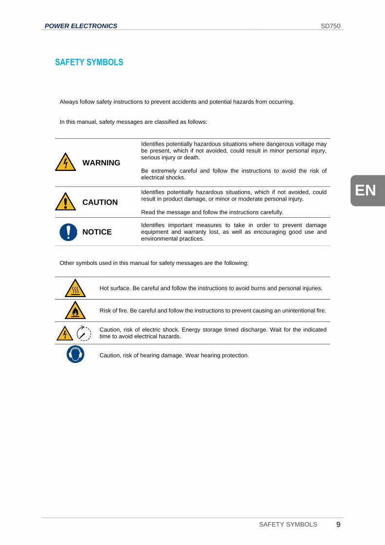
SAFETY SYMBOLS
Always follow safety instructions to prevent accidents and potential hazards from occurring.
In this manual, safety messages are classified as follows:
Other symbols used in this manual for safety messages are the following:
WARNING
Identifies potentially hazardous situations where dangerous voltage may be present, which if not avoided, could result in minor personal injury, serious injury or death. Be extremely careful and follow the instructions to avoid the risk of electrical shocks.
CAUTION
Identifies potentially hazardous situations, which if not avoided, could result in product damage, or minor or moderate personal injury. Read the message and follow the instructions carefully.
NOTICE Identifies important measures to take in order to prevent damage equipment and warranty lost, as well as encouraging good use and environmental practices.
Hot surface. Be careful and follow the instructions to avoid burns and personal injuries.
Risk of fire. Be careful and follow the instructions to prevent causing an unintentional fire.
Caution, risk of electric shock. Energy storage timed discharge. Wait for the indicated time to avoid electrical hazards.
Caution, risk of hearing damage. Wear hearing protection.
SD750 POWER ELECTRONICS
10 SAFETY INSTRUCTIONS
SAFETY INSTRUCTIONS
IMPORTANT!
Read carefully this manual to maximize the performance of the product and to ensure its safe use.
In order to appropriately use the drive, please, follow all instructions described in the Hardware and
Installation Manual which refer to transportation, installation, electrical connection and commissioning of
the equipment.
Power Electronics accepts no responsibility or liability for partial or total damages resulting from incorrect
use of equipment.
CAUTION
Read carefully the Hardware and Installation Manual and all documentation related to the drive to ensure its safe use and prevent personal injuries and equipment damage.
Comply with local and national regulation.
POWER ELECTRONICS SD750
DISPLAY UNIT AND CONTROL KEYPAD 11
EN
1. DISPLAY UNIT AND CONTROL KEYPAD
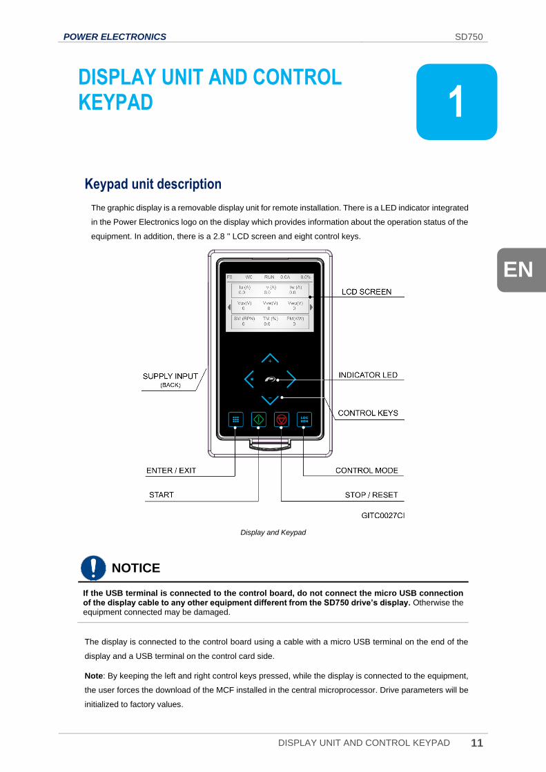
Keypad unit description
The graphic display is a removable display unit for remote installation. There is a LED indicator integrated
in the Power Electronics logo on the display which provides information about the operation status of the
equipment. In addition, there is a 2.8 '' LCD screen and eight control keys.
Display and Keypad
NOTICE
If the USB terminal is connected to the control board, do not connect the micro USB connection of the display cable to any other equipment different from the SD750 drive’s display. Otherwise the equipment connected may be damaged.
The display is connected to the control board using a cable with a micro USB terminal on the end of the
display and a USB terminal on the control card side.
Note: By keeping the left and right control keys pressed, while the display is connected to the equipment,
the user forces the download of the MCF installed in the central microprocessor. Drive parameters will be
initialized to factory values.
1
SD750 POWER ELECTRONICS
12 DISPLAY UNIT AND CONTROL KEYPAD
LED for status indication
The status LED shows the drive status while it is on. It is located in the Power Electronics logo, and
will change its color as follows:
• Green: The equipment is in run status.
• Red: The equipment has stopped due to a FAULT.
• Yellow: The equipment is in WARNING status.
Alphanumeric LCD display
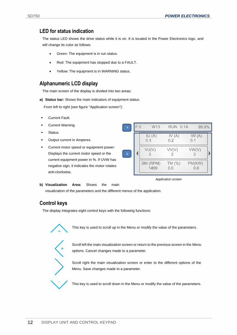
The main screen of the display is divided into two areas:
a) Status bar: Shows the main indicators of equipment status.
From left to right (see figure "Application screen"):
Current Fault.
Current Warning.
Status.
Output current in Amperes.
Current motor speed or equipment power:
Displays the current motor speed or the
current equipment power in %. If UVW has
negative sign, it indicates the motor rotates
anti-clockwise.
b) Visualization Area: Shows the main
visualization of the parameters and the different menus of the application.
Control keys
The display integrates eight control keys with the following functions:
This key is used to scroll up in the Menu or modify the value of the parameters.
Scroll left the main visualization screen or return to the previous screen in the Menu
options. Cancel changes made to a parameter.
Scroll right the main visualization screen or enter to the different options of the
Menu. Save changes made to a parameter.
This key is used to scroll down in the Menu or modify the value of the parameters.
Application screen
b
a
POWER ELECTRONICS SD750
DISPLAY UNIT AND CONTROL KEYPAD 13
EN
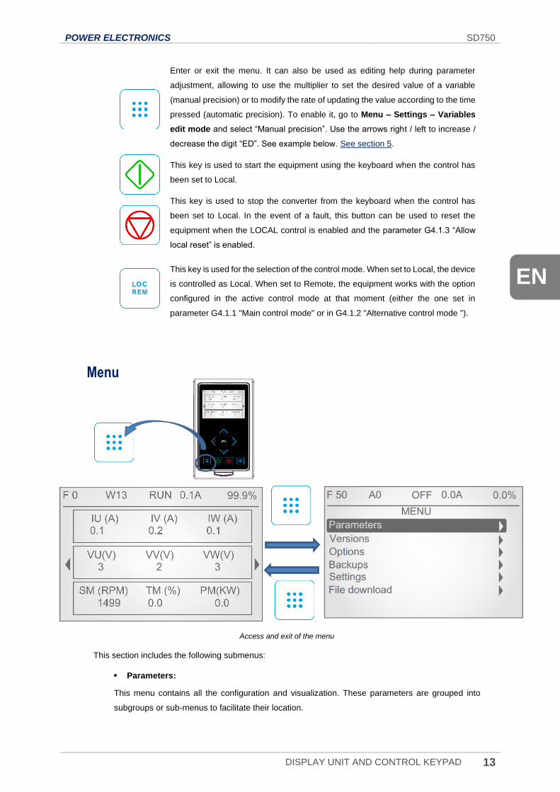
Enter or exit the menu. It can also be used as editing help during parameter
adjustment, allowing to use the multiplier to set the desired value of a variable
(manual precision) or to modify the rate of updating the value according to the time
pressed (automatic precision). To enable it, go to Menu – Settings – Variables
edit mode and select “Manual precision”. Use the arrows right / left to increase /
decrease the digit “ED”. See example below. See section 5.
This key is used to start the equipment using the keyboard when the control has
been set to Local.
This key is used to stop the converter from the keyboard when the control has
been set to Local. In the event of a fault, this button can be used to reset the
equipment when the LOCAL control is enabled and the parameter G4.1.3 “Allow
local reset” is enabled.
This key is used for the selection of the control mode. When set to Local, the device
is controlled as Local. When set to Remote, the equipment works with the option
configured in the active control mode at that moment (either the one set in
parameter G4.1.1 "Main control mode" or in G4.1.2 "Alternative control mode ").
Menu
Access and exit of the menu
This section includes the following submenus:
Parameters:
This menu contains all the configuration and visualization. These parameters are grouped into
subgroups or sub-menus to facilitate their location.
SD750 POWER ELECTRONICS
14 DISPLAY UNIT AND CONTROL KEYPAD
Versions:
This menu contains the information of the versions associated with the equipment in terms of MCF,
uP, DSP, HW, expansion board and display.
Custom view creator:
This menu allows creating custom display screens on the main screen, selecting the parameters to
be included for any of the three lines of the new screen to be customized. Once the line to be
configured is selected, the user can select the three parameters to be included in the line. When
leaving the configuration, the screen will be automatically created on the right side of the Home
screen.
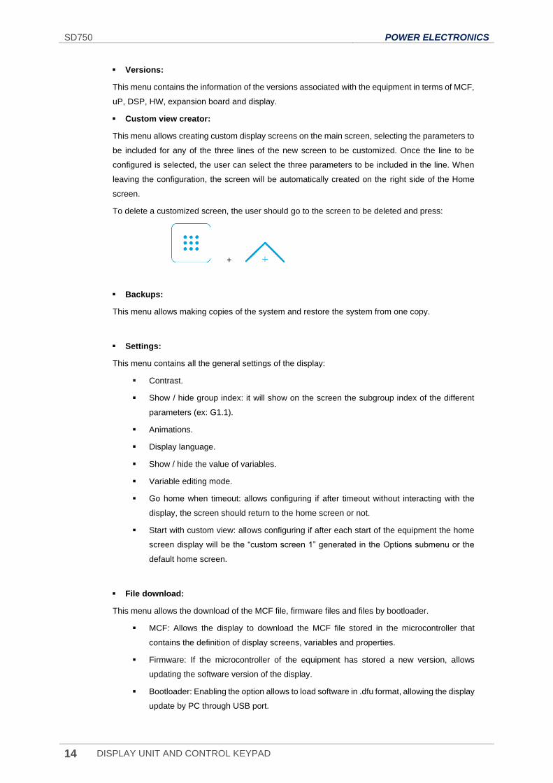
To delete a customized screen, the user should go to the screen to be deleted and press:
+
Backups:
This menu allows making copies of the system and restore the system from one copy.
Settings:
This menu contains all the general settings of the display:
Contrast.
Show / hide group index: it will show on the screen the subgroup index of the different
parameters (ex: G1.1).
Animations.
Display language.
Show / hide the value of variables.
Variable editing mode.
Go home when timeout: allows configuring if after timeout without interacting with the
display, the screen should return to the home screen or not.
Start with custom view: allows configuring if after each start of the equipment the home
screen display will be the “custom screen 1” generated in the Options submenu or the
default home screen.
File download:
This menu allows the download of the MCF file, firmware files and files by bootloader.
MCF: Allows the display to download the MCF file stored in the microcontroller that
contains the definition of display screens, variables and properties.
Firmware: If the microcontroller of the equipment has stored a new version, allows
updating the software version of the display.
Bootloader: Enabling the option allows to load software in .dfu format, allowing the display
update by PC through USB port.
POWER ELECTRONICS SD750
STATUS & WARNING MESSAGES 15
EN
2. STATUS & WARNING MESSAGES
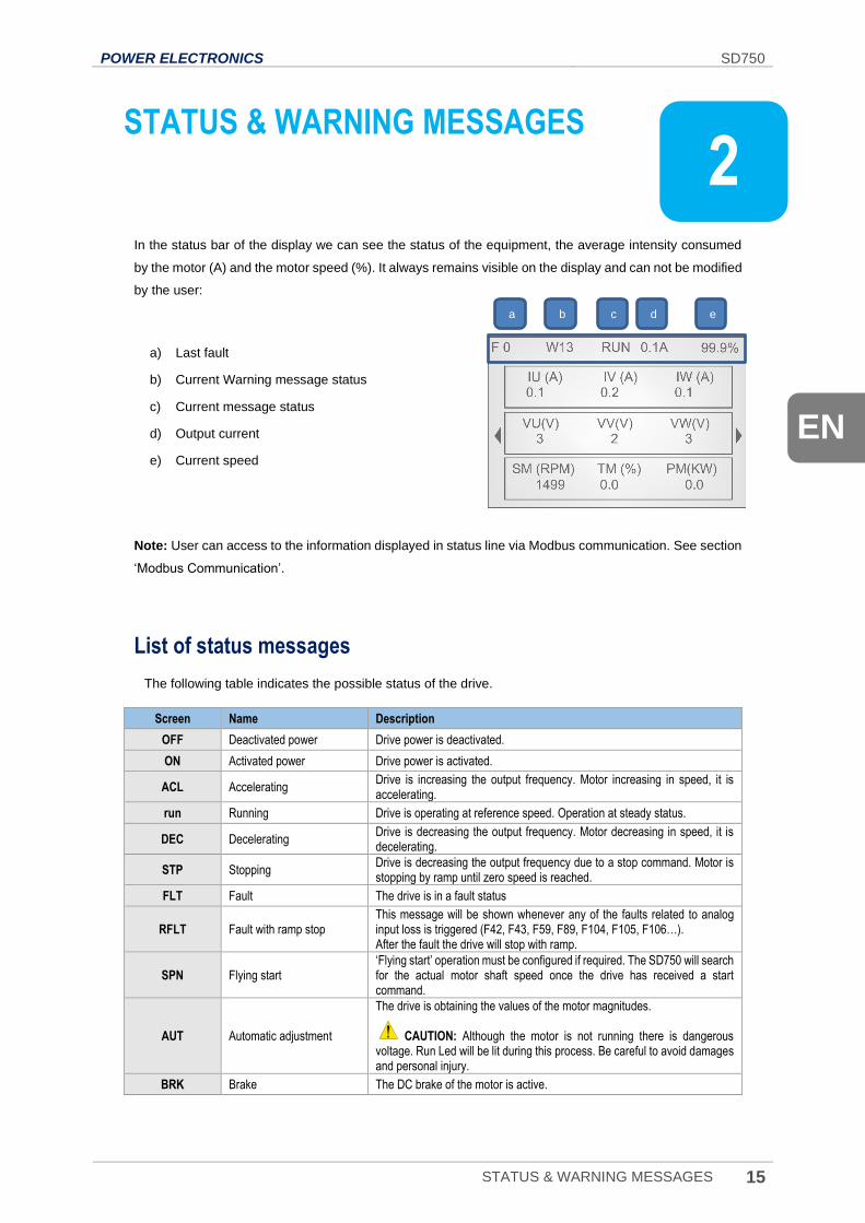
In the status bar of the display we can see the status of the equipment, the average intensity consumed
by the motor (A) and the motor speed (%). It always remains visible on the display and can not be modified
by the user:
a) Last fault
b) Current Warning message status
c) Current message status
d) Output current
e) Current speed
Note: User can access to the information displayed in status line via Modbus communication. See section
‘Modbus Communication’.
List of status messages
The following table indicates the possible status of the drive.
Screen Name Description
OFF Deactivated power Drive power is deactivated.
ON Activated power Drive power is activated.
ACL Accelerating Drive is increasing the output frequency. Motor increasing in speed, it is accelerating.
run Running Drive is operating at reference speed. Operation at steady status.
DEC Decelerating Drive is decreasing the output frequency. Motor decreasing in speed, it is decelerating.
STP Stopping Drive is decreasing the output frequency due to a stop command. Motor is stopping by ramp until zero speed is reached.
FLT Fault The drive is in a fault status
RFLT Fault with ramp stop This message will be shown whenever any of the faults related to analog input loss is triggered (F42, F43, F59, F89, F104, F105, F106…). After the fault the drive will stop with ramp.
SPN Flying start ‘Flying start’ operation must be configured if required. The SD750 will search for the actual motor shaft speed once the drive has received a start command.
AUT Automatic adjustment
The drive is obtaining the values of the motor magnitudes. CAUTION: Although the motor is not running there is dangerous voltage. Run Led will be lit during this process. Be careful to avoid damages and personal injury.
BRK Brake The DC brake of the motor is active.
2
a b c d e
SD750 POWER ELECTRONICS
16 STATUS & WARNING MESSAGES
Screen Name Description
IHEAT Non-condensing current is activated
SD750 is injecting DC current to prevent moisture condensing within the motor. CAUTION: Although the motor is not running there is dangerous voltage. Run Led will be lit during this process. Be careful to avoid damages and personal injury.
DLY Start Delay Time When a delay time has been set in order to start the equipment, after the start command has been activated, this message will be displayed until this time has elapsed.
IS1 Inch speed 1
SD750 is working according to inch speed 1 command and ‘Start + Inch speed 1' mode is active. When operated in this mode the ‘Start + Inch speed 1’ command is dominant over other inputs programmed for ‘Start’ functionality. Therefore, if one input is configured as ‘Start’ and it is deactivated; despite this deactivated input, the drive will start when ‘Start + Inch speed 1' command is received. This is also valid for Inch speed 2 and 3.
IS2 Inch speed 2 SD750 is working according to inch speed 2 command. ‘Start + Inch speed 2' mode is active.
IS3 Inch speed 3 SD750 is working according to inch speed 3 command. ‘Start + Inch speed 3' mode is active.
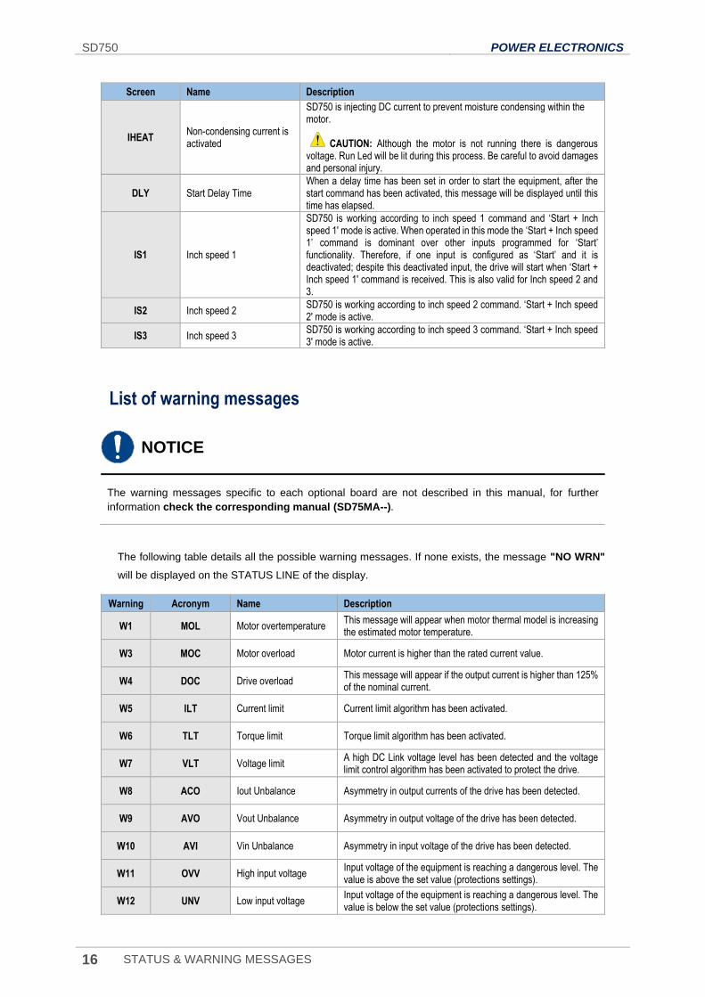
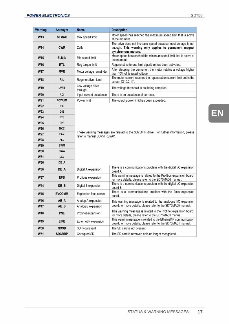
List of warning messages
NOTICE
The warning messages specific to each optional board are not described in this manual, for further
information check the corresponding manual (SD75MA--).
The following table details all the possible warning messages. If none exists, the message "NO WRN"
will be displayed on the STATUS LINE of the display.
Warning Acronym Name Description
W1 MOL Motor overtemperature This message will appear when motor thermal model is increasing the estimated motor temperature.
W3 MOC Motor overload Motor current is higher than the rated current value.
W4 DOC Drive overload This message will appear if the output current is higher than 125% of the nominal current.
W5 ILT Current limit Current limit algorithm has been activated.
W6 TLT Torque limit Torque limit algorithm has been activated.
W7 VLT Voltage limit A high DC Link voltage level has been detected and the voltage limit control algorithm has been activated to protect the drive.
W8 ACO Iout Unbalance Asymmetry in output currents of the drive has been detected.
W9 AVO Vout Unbalance Asymmetry in output voltage of the drive has been detected.
W10 AVI Vin Unbalance Asymmetry in input voltage of the drive has been detected.
W11 OVV High input voltage Input voltage of the equipment is reaching a dangerous level. The value is above the set value (protections settings).
W12 UNV Low input voltage Input voltage of the equipment is reaching a dangerous level. The value is below the set value (protections settings).
POWER ELECTRONICS SD750
STATUS & WARNING MESSAGES 17
EN
Warning Acronym Name Description
W13 SLMAX Max speed limit Motor speed has reached the maximum speed limit that is active at the moment.
W14 CWR Cells The drive does not increase speed because input voltage is not enough. This warning only applies to permanent magnet synchronous motors.
W15 SLMIN Min speed limit Motor speed has reached the minimum speed limit that is active at the moment.
W16 RTL Reg torque limit Regenerative torque limit algorithm has been activated.
W17 MVR Motor voltage remainder After stopping the converter, the motor retains a voltage higher than 10% of its rated voltage.
W18 RIL Regenerative I Limit The motor current reaches the regeneration current limit set in the screen [G10.2.11].
W19 LVRT Low voltage drive-through
The voltage threshold is not being complied.
W20 ACI Input current unbalance There is an unbalance of currents.
W21 POWLIM Power limit The output power limit has been exceeded.
W22 PIE
These warning messages are related to the SD750FR drive. For further information, please refer to manual SD75FRSW01.
W23 DIE
W24 FTE
W25 TPR
W26 MCC
W27 FAV
W28 PLL
W29 SWM
W30 DWA
W31 LCL
W36 DE_A
W36 DE_A Digital A expansion There is a communications problem with the digital I/O expansion board A.
W37 EPB Profibus expansion This warning message is related to the Profibus expansion board, for more details, please refer to the SD75MA06 manual.
W44 DE_B Digital B expansion There is a communications problem with the digital I/O expansion board B.
W45 EVCOMM Expansion fans comm There is a communications problem with the fan’s expansion board.
W46 AE_A Analog A expansion This warning message is related to the analogue I/O expansion board, for more details, please refer to the SD75MA05 manual. W47 AE_B Analog B expansion
W48 PNE Profinet expansion This warning message is related to the Profinet expansion board, for more details, please refer to the SD75MA03 manual.
W49 EIPE EthernetIP expansion This warning message is related to the Ethernet/IP communication board, for more details, please refer to the SD75MA01 manual.
W50 NOSD SD not present The SD card is not present.
W51 SDCRRP Corrupted SD The SD card is removed or is no longer recognized.
SD750 POWER ELECTRONICS
18 FAULT MESSAGES. DESCRIPTIONS AND ACTIONS
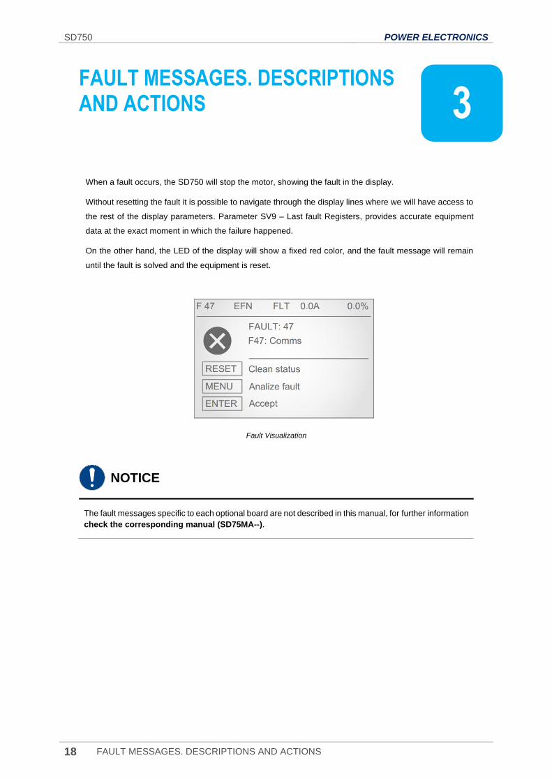
3. FAULT MESSAGES. DESCRIPTIONS AND ACTIONS
When a fault occurs, the SD750 will stop the motor, showing the fault in the display.
Without resetting the fault it is possible to navigate through the display lines where we will have access to
the rest of the display parameters. Parameter SV9 – Last fault Registers, provides accurate equipment
data at the exact moment in which the failure happened.
On the other hand, the LED of the display will show a fixed red color, and the fault message will remain
until the fault is solved and the equipment is reset.
Fault Visualization
NOTICE
The fault messages specific to each optional board are not described in this manual, for further information
check the corresponding manual (SD75MA--).
3
POWER ELECTRONICS SD750
FAULT MESSAGES. DESCRIPTIONS AND ACTIONS 19
EN
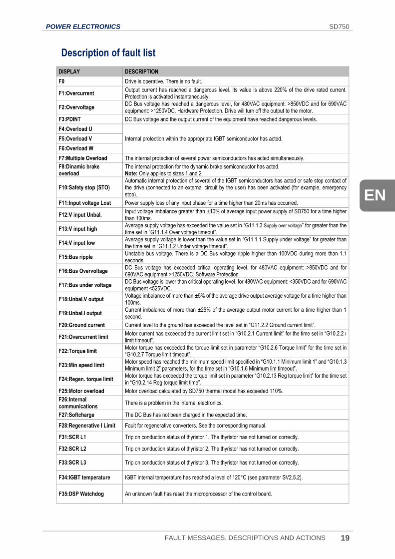
Description of fault list
DISPLAY DESCRIPTION
F0 Drive is operative. There is no fault.
F1:Overcurrent Output current has reached a dangerous level. Its value is above 220% of the drive rated current. Protection is activated instantaneously.
F2:Overvoltage DC Bus voltage has reached a dangerous level, for 480VAC equipment: >850VDC and for 690VAC equipment: >1250VDC. Hardware Protection. Drive will turn off the output to the motor.
F3:PDINT DC Bus voltage and the output current of the equipment have reached dangerous levels.
F4:Overload U
Internal protection within the appropriate IGBT semiconductor has acted. F5:Overload V
F6:Overload W
F7:Multiple Overload The internal protection of several power semiconductors has acted simultaneously.
F8:Dinamic brake overload
The internal protection for the dynamic brake semiconductor has acted. Note: Only applies to sizes 1 and 2.
F10:Safety stop (STO) Automatic internal protection of several of the IGBT semiconductors has acted or safe stop contact of the drive (connected to an external circuit by the user) has been activated (for example, emergency stop).
F11:Input voltage Lost Power supply loss of any input phase for a time higher than 20ms has occurred.
F12:V input Unbal. Input voltage imbalance greater than ±10% of average input power supply of SD750 for a time higher than 100ms.
F13:V input high Average supply voltage has exceeded the value set in “G11.1.3 Supply over voltage” for greater than the time set in “G11.1.4 Over voltage timeout”.
F14:V input low Average supply voltage is lower than the value set in “G11.1.1 Supply under voltage” for greater than the time set in “G11.1.2 Under voltage timeout”.
F15:Bus ripple Unstable bus voltage. There is a DC Bus voltage ripple higher than 100VDC during more than 1.1 seconds.
F16:Bus Overvoltage DC Bus voltage has exceeded critical operating level, for 480VAC equipment: >850VDC and for 690VAC equipment >1250VDC. Software Protection.
F17:Bus under voltage DC Bus voltage is lower than critical operating level, for 480VAC equipment: <350VDC and for 690VAC equipment <525VDC.
F18:Unbal.V output Voltage imbalance of more than ±5% of the average drive output average voltage for a time higher than 100ms.
F19:Unbal.I output Current imbalance of more than ±25% of the average output motor current for a time higher than 1 second.
F20:Ground current Current level to the ground has exceeded the level set in “G11.2.2 Ground current limit”.
F21:Overcurrent limit Motor current has exceeded the current limit set in “G10.2.1 Current limit” for the time set in “G10.2.2 I limit timeout”.
F22:Torque limit Motor torque has exceeded the torque limit set in parameter “G10.2.6 Torque limit” for the time set in “G10.2.7 Torque limit timeout”.
F23:Min speed limit Motor speed has reached the minimum speed limit specified in “G10.1.1 Minimum limit 1” and “G10.1.3 Minimum limit 2” parameters, for the time set in “G10.1.6 Minimum lim timeout”.
F24:Regen. torque limit Motor torque has exceeded the torque limit set in parameter “G10.2.13 Reg torque limit” for the time set in “G10.2.14 Reg torque limit time”.
F25:Motor overload Motor overload calculated by SD750 thermal model has exceeded 110%.
F26:Internal communications
There is a problem in the internal electronics.
F27:Softcharge The DC Bus has not been charged in the expected time.
F28:Regenerative I Limit Fault for regenerative converters. See the corresponding manual.
F31:SCR L1 Trip on conduction status of thyristor 1. The thyristor has not turned on correctly.
F32:SCR L2 Trip on conduction status of thyristor 2. The thyristor has not turned on correctly.
F33:SCR L3 Trip on conduction status of thyristor 3. The thyristor has not turned on correctly.
F34:IGBT temperature IGBT internal temperature has reached a level of 120°C (see parameter SV2.5.2).
F35:DSP Watchdog An unknown fault has reset the microprocessor of the control board.
SD750 POWER ELECTRONICS
20 FAULT MESSAGES. DESCRIPTIONS AND ACTIONS
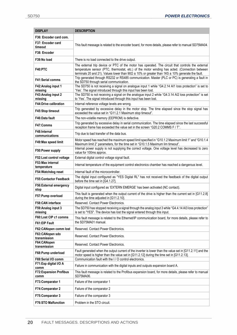
DISPLAY DESCRIPTION
F36: Encoder card com.
This fault message is related to the encoder board, for more details, please refer to manual SD75MA04. F37: Encoder card timeout
F38: Encoder
F39:No load There is no load connected to the drive output.
F40:PTC The external trip device or PTC of the motor has operated. The circuit that controls the external temperature sensor (PTC, thermostat, etc.) of the motor winding has acted. (Connection between terminals 20 and 21). Values lower than 90Ω ± 10% or greater than 1K5 ± 10% generate the fault.
F41:Serial comms Trip generated through RS232 or RS485 communication. Master (PLC or PC) is generating a fault in the SD750 through serial communication.
F42:Analog input 1 missing
The SD750 is not receiving a signal on analogue input 1 while “G4.2.14 AI1 loss protection” is set to ‘Yes’. The signal introduced through this input has been lost.
F43:Analog input 2 missing
The SD750 is not receiving a signal on the analogue input 2 while “G4.3.14 AI2 loss protection” is set to ‘Yes’. The signal introduced through this input has been lost.
F44:Drive calibration Internal reference voltage levels are wrong.
F45:Stop timeout Trip generated by excessive delay in the motor stop. The time elapsed since the stop signal has exceeded the value set in “G11.2.1 Maximum stop timeout”.
F46:Data fault The non-volatile memory (EEPROM) is defective.
F47:Comms Trip generated by excessive delay in serial communication. The time elapsed since the last successful reception frame has exceeded the value set in the screen “G20.2 COMMS F / T”.
F48:Internal communications
Trip due to bad transfer of the data bus.
F49:Max speed limit Motor speed has reached the maximum speed limit specified in “G10.1.2 Maximum limit 1” and “G10.1.4 Maximum limit 2” parameters, for the time set in “G10.1.5 Maximum lim timeout”.
F50:Power supply Internal power supply is not supplying the correct voltage. One voltage level has decreased to zero value for 100ms approx.
F52:Lost control voltage External digital control voltage signal fault.
F53:Max internal temperature
Internal temperature of the equipment control electronics chamber has reached a dangerous level.
F54:Watchdog reset Internal fault of the microcontroller.
F55:Contactor Feedback The digital input configured as "YES Digital RL" has not received the feedback of the digital output before the time set in [G4.1.27].
F56:External emergency stop
Digital input configured as ‘EXTERN EMERGE’ has been activated (NC contact).
F57:Pump overload This fault is generated when the output current of the drive is higher than the current set in [G11.2.8] during the time adjusted in [G11.2.10].
F58:CAN interface Reserved. Contact Power Electronics.
F59:Analog input 3 missing
The SD750 has stopped receiving a signal through the analog input 3 while “G4.4.14 AI3 loss protection” is set to "YES". The device has lost the signal entered through this input.
F60:Lost CIP c1 comms This fault message is related to the Ethernet/IP communication board, for more details, please refer to the SD75MA01 manual. F61:EIP Fault
F62:CANopen comm lost Reserved. Contact Power Electronics.
F63:CANopen sdo transmission
Reserved. Contact Power Electronics.
F64:CANopen transmission
Reserved. Contact Power Electronics.
F68:Pump underload Fault generated when the output current of the inverter is lower than the value set in [G11.2.11] and the motor speed is higher than the value set in [G11.2.12] during the time set in [G11.2.13].
F69:Serial I/O comm Communication fault with the I / O control electronics.
F71:Exp digital I/O A comm
Failure in communication with the digital inputs and outputs expansion board A.
F72:Expansion Profibus comm
This fault message is related to the Profibus expansion board, for more details, please refer to manual SD75MA06.
F73:Comparator 1 Failure of the comparator 1
F74:Comparator 2 Failure of the comparator 2
F75:Comparator 3 Failure of the comparator 3
F76:STO Malfunction Problem in the STO circuit.
POWER ELECTRONICS SD750
FAULT MESSAGES. DESCRIPTIONS AND ACTIONS 21
EN
DISPLAY DESCRIPTION
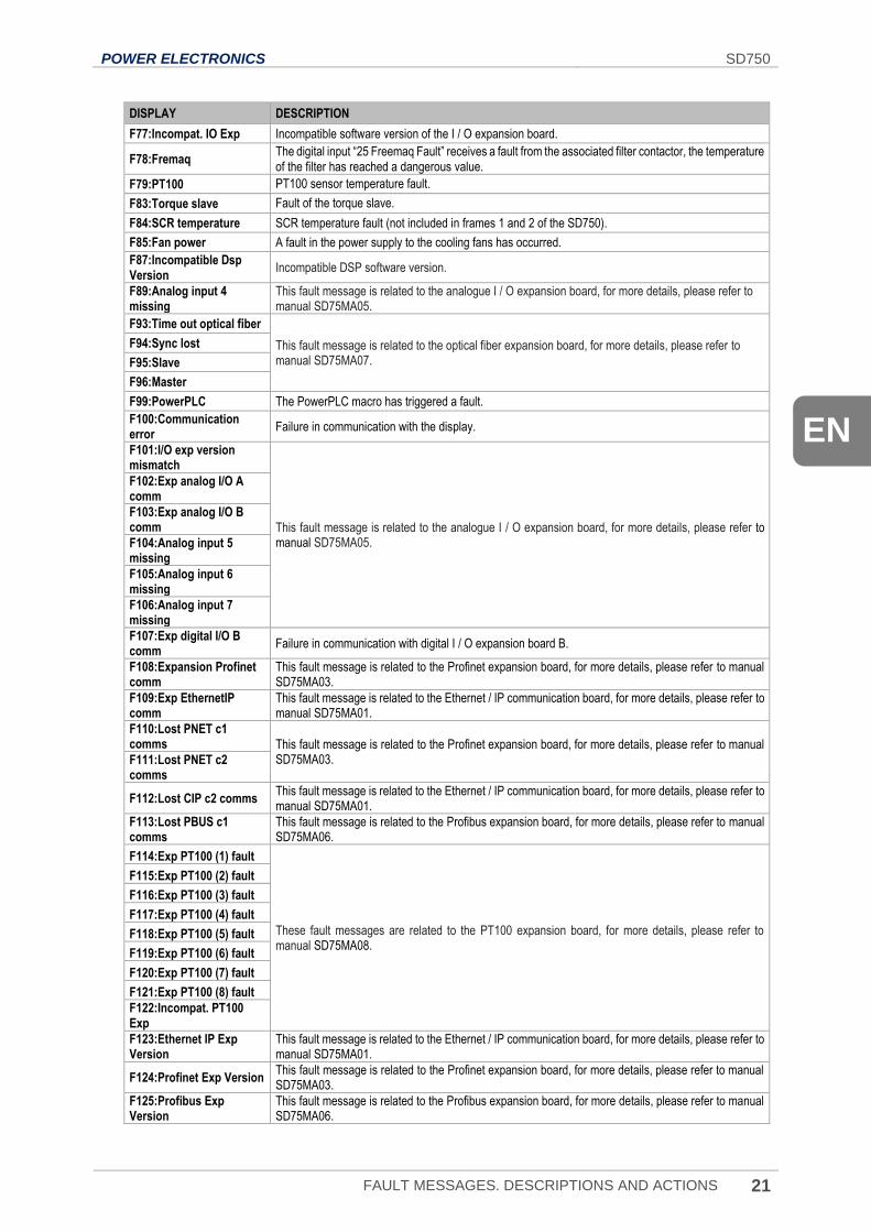
F77:Incompat. IO Exp Incompatible software version of the I / O expansion board.
F78:Fremaq The digital input “25 Freemaq Fault” receives a fault from the associated filter contactor, the temperature of the filter has reached a dangerous value.
F79:PT100 PT100 sensor temperature fault.
F83:Torque slave Fault of the torque slave.
F84:SCR temperature SCR temperature fault (not included in frames 1 and 2 of the SD750).
F85:Fan power A fault in the power supply to the cooling fans has occurred.
F87:Incompatible Dsp Version
Incompatible DSP software version.
F89:Analog input 4 missing
This fault message is related to the analogue I / O expansion board, for more details, please refer to manual SD75MA05.
F93:Time out optical fiber
This fault message is related to the optical fiber expansion board, for more details, please refer to manual SD75MA07.
F94:Sync lost
F95:Slave
F96:Master
F99:PowerPLC The PowerPLC macro has triggered a fault.
F100:Communication error
Failure in communication with the display.
F101:I/O exp version mismatch
This fault message is related to the analogue I / O expansion board, for more details, please refer to manual SD75MA05.
F102:Exp analog I/O A comm
F103:Exp analog I/O B comm
F104:Analog input 5 missing
F105:Analog input 6 missing
F106:Analog input 7 missing
F107:Exp digital I/O B comm
Failure in communication with digital I / O expansion board B.
F108:Expansion Profinet comm
This fault message is related to the Profinet expansion board, for more details, please refer to manual SD75MA03.
F109:Exp EthernetIP comm
This fault message is related to the Ethernet / IP communication board, for more details, please refer to manual SD75MA01.
F110:Lost PNET c1 comms This fault message is related to the Profinet expansion board, for more details, please refer to manual
SD75MA03. F111:Lost PNET c2 comms
F112:Lost CIP c2 comms This fault message is related to the Ethernet / IP communication board, for more details, please refer to manual SD75MA01.
F113:Lost PBUS c1 comms
This fault message is related to the Profibus expansion board, for more details, please refer to manual SD75MA06.
F114:Exp PT100 (1) fault
These fault messages are related to the PT100 expansion board, for more details, please refer to manual SD75MA08.
F115:Exp PT100 (2) fault
F116:Exp PT100 (3) fault
F117:Exp PT100 (4) fault
F118:Exp PT100 (5) fault
F119:Exp PT100 (6) fault
F120:Exp PT100 (7) fault
F121:Exp PT100 (8) fault
F122:Incompat. PT100 Exp
F123:Ethernet IP Exp Version
This fault message is related to the Ethernet / IP communication board, for more details, please refer to manual SD75MA01.
F124:Profinet Exp Version This fault message is related to the Profinet expansion board, for more details, please refer to manual SD75MA03.
F125:Profibus Exp Version
This fault message is related to the Profibus expansion board, for more details, please refer to manual SD75MA06.
SD750 POWER ELECTRONICS
22 FAULT MESSAGES. DESCRIPTIONS AND ACTIONS
DISPLAY DESCRIPTION
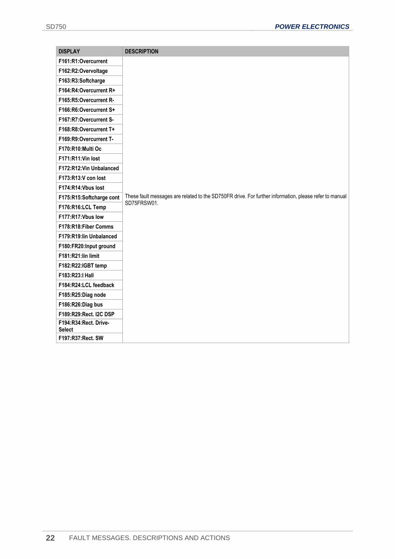
F161:R1:Overcurrent
These fault messages are related to the SD750FR drive. For further information, please refer to manual SD75FRSW01.
F162:R2:Overvoltage
F163:R3:Softcharge
F164:R4:Overcurrent R+
F165:R5:Overcurrent R-
F166:R6:Overcurrent S+
F167:R7:Overcurrent S-
F168:R8:Overcurrent T+
F169:R9:Overcurrent T-
F170:R10:Multi Oc
F171:R11:Vin lost
F172:R12:Vin Unbalanced
F173:R13:V con lost
F174:R14:Vbus lost
F175:R15:Softcharge cont
F176:R16:LCL Temp
F177:R17:Vbus low
F178:R18:Fiber Comms
F179:R19:Iin Unbalanced
F180:FR20:Input ground
F181:R21:Iin limit
F182:R22:IGBT temp
F183:R23:I Hall
F184:R24:LCL feedback
F185:R25:Diag node
F186:R26:Diag bus
F189:R29:Rect. I2C DSP
F194:R34:Rect. Drive-Select
F197:R37:Rect. SW
POWER ELECTRONICS SD750
FAULT MESSAGES. DESCRIPTIONS AND ACTIONS 23
EN
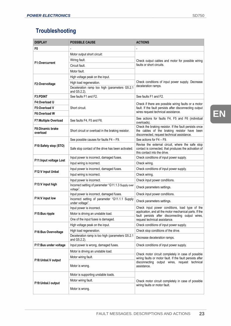
Troubleshooting
DISPLAY POSSIBLE CAUSE ACTIONS
F0 - -
F1:Overcurrent
Motor output short circuit:
Check output cables and motor for possible wiring faults or short circuits.
Wiring fault.
Circuit fault.
Motor fault.
F2:Overvoltage
High voltage peak on the input.
Check conditions of input power supply. Decrease deceleration ramps.
High load regeneration.
Deceleration ramp too high (parameters G5.2.1 and G5.2.2).
F3:PDINT See faults F1 and F2. See faults F1 and F2.
F4:Overload U
Short circuit. Check if there are possible wiring faults or a motor fault. If the fault persists after disconnecting output wires request technical assistance.
F5:Overload V
F6:Overload W
F7:Multiple Overload See faults F4, F5 and F6. See actions for faults F4, F5 and F6 (individual overloads).
F8:Dinamic brake overload
Short circuit or overload in the braking resistor. Check the braking resistor. If the fault persists once the cables of the braking resistor have been disconnected, request technical assistance.
F10:Safety stop (STO)
See possible causes for faults F4 – F9. See actions for F4 – F9.
Safe stop contact of the drive has been activated. Revise the external circuit, where the safe stop contact is connected, that produces the activation of this contact into the drive.
F11:Input voltage Lost Input power is incorrect, damaged fuses. Check conditions of input power supply.
Input wiring is incorrect. Check wiring.
F12:V input Unbal Input power is incorrect, damaged fuses. Check conditions of input power supply.
Input wiring is incorrect. Check wiring.
F13:V input high
Input power is incorrect. Check input power conditions.
Incorrect setting of parameter “G11.1.3 Supply over
voltage”. Check parameters settings.
F14:V input low
Input power is incorrect, damaged fuses. Check input power conditions.
Incorrect setting of parameter “G11.1.1 Supply under voltage”.
Check parameters settings.
F15:Bus ripple
Input power is incorrect. Check input power conditions, load type of the application, and all the motor mechanical parts. If the fault persists after disconnecting output wires, request technical assistance.
Motor is driving an unstable load.
One of the input fuses is damaged.
F16:Bus Overvoltage
High voltage peak on the input. Check conditions of input power supply.
High load regeneration. Check stop conditions of the drive.
Deceleration ramp is too high (parameters G5.2.1 and G5.2.2).
Decrease deceleration ramps.
F17:Bus under voltage Input power is wrong, damaged fuses. Check conditions of input power supply.
F18:Unbal.V output
Motor is driving an unstable load. Check motor circuit completely in case of possible wiring faults or motor fault. If the fault persists after disconnecting output wires, request technical assistance.
Motor wiring fault.
Motor is wrong.
F19:Unbal.I output
Motor is supporting unstable loads.
Check motor circuit completely in case of possible wiring faults or motor fault.
Motor wiring fault.
Motor is wrong.
SD750 POWER ELECTRONICS
24 FAULT MESSAGES. DESCRIPTIONS AND ACTIONS
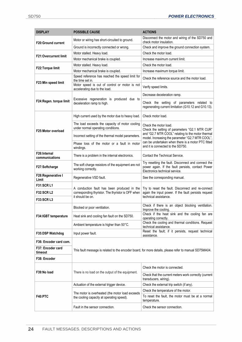
DISPLAY POSSIBLE CAUSE ACTIONS
F20:Ground current Motor or wiring has short-circuited to ground.
Disconnect the motor and wiring of the SD750 and check motor insulation.
Ground is incorrectly connected or wrong. Check and improve the ground connection system.
F21:Overcurrent limit Motor stalled. Heavy load. Check the motor load.
Motor mechanical brake is coupled. Increase maximum current limit.
F22:Torque limit Motor stalled. Heavy load. Check the motor load.
Motor mechanical brake is coupled. Increase maximum torque limit.
F23:Min speed limit
Speed reference has reached the speed limit for the time set in.
Check the reference source and the motor load.
Motor speed is out of control or motor is not accelerating due to the load.
Verify speed limits.
F24:Regen. torque limit Excessive regeneration is produced due to deceleration ramp to high.
Decrease deceleration ramp.
Check the setting of parameters related to regenerating current limitation (G10.12 and G10.13).
F25:Motor overload
High current used by the motor due to heavy load. Check motor load.
The load exceeds the capacity of motor cooling under normal operating conditions.
Check the motor load. Check the setting of parameters “G2.1 MTR CUR” and “G2.7 MTR COOL” relating to the motor thermal model. Increasing the parameter “G2.7 MTR COOL”, can be undertaken when there is a motor PTC fitted and it is connected to the SD750.
Incorrect setting of the thermal model parameters.
Phase loss of the motor or a fault in motor windings.
F26:Internal communications
There is a problem in the internal electronics. Contact the Technical Service.
F27:Softcharge The soft charge resistors of the equipment are not working correctly.
Try resetting the fault. Disconnect and connect the power again. If the fault persists, contact Power Electronics technical service.
F28:Regenerative I Limit
Regenerative VSD fault. See the corresponding manual.
F31:SCR L1 A conduction fault has been produced in the corresponding thyristor. The thyristor is OFF when it should be on.
Try to reset the fault. Disconnect and re-connect again the input power. If the fault persists request technical assistance.
F32:SCR L2
F33:SCR L3
F34:IGBT temperature
Blocked or poor ventilation. Check if there is an object blocking ventilation. Improve the cooling.
Heat sink and cooling fan fault on the SD750. Check if the heat sink and the cooling fan are operating correctly.
Ambient temperature is higher than 50°C. Check the cooling and thermal conditions. Request technical assistance.
F35:DSP Watchdog Input power fault. Reset the fault; if it persists, request technical assistance.
F36: Encoder card com.
This fault message is related to the encoder board, for more details, please refer to manual SD75MA04. F37: Encoder card timeout
F38: Encoder
F39:No load There is no load on the output of the equipment.
Check the motor is connected.
Check that the current meters work correctly (current transducers, wiring).
F40:PTC
Actuation of the external trigger device. Check the external trip switch (if any).
The motor is overheated (the motor load exceeds the cooling capacity at operating speed).
Check the temperature of the motor.
To reset the fault, the motor must be at a normal temperature.
Fault in the sensor connection. Check the sensor connection.
POWER ELECTRONICS SD750
FAULT MESSAGES. DESCRIPTIONS AND ACTIONS 25
EN
DISPLAY POSSIBLE CAUSE ACTIONS
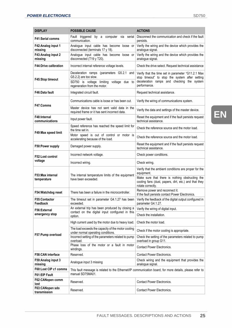
F41:Serial comms Fault triggered by a computer via serial communication.
Disconnect the communication and check if the fault persists.
F42:Analog input 1 missing
Analogue input cable has become loose or disconnected (terminals 17 y 18).
Verify the wiring and the device which provides the analogue signal.
F43:Analog input 2 missing
Analogue input cable has become loose or disconnected (T19 y T20).
Verify the wiring and the device which provides the analogue signal.
F44:Drive calibration Incorrect internal reference voltage levels. Check the drive select. Request technical assistance
F45:Stop timeout
Deceleration ramps (parameters G5.2.1 and G5.2.2) are too slow.
Verify that the time set in parameter “G11.2.1 Max stop timeout” to stop the system after setting deceleration ramps and checking the system performance.
SD750 is voltage limiting voltage due to regeneration from the motor.
F46:Data fault Integrated circuit fault. Request technical assistance.
F47:Comms
Communications cable is loose or has been cut. Verify the wiring of communications system.
Master device has not sent valid data in the required frame or it has sent incorrect data.
Verify the data and settings of the master device.
F48:Internal communications
Input power fault. Reset the equipment and if the fault persists request technical assistance.
F49:Max speed limit
Speed reference has reached the speed limit for the time set in.
Check the reference source and the motor load.
Motor speed is out of control or motor is accelerating because of the load.
Check the reference source and the motor load.
F50:Power supply Damaged power supply. Reset the equipment and if the fault persists request technical assistance.
F52:Lost control voltage
Incorrect network voltage. Check power conditions.
Incorrect wiring. Check wiring.
F53:Max internal temperature
The internal temperature limits of the equipment have been exceeded.
Verify that the ambient conditions are proper for the equipment.
Make sure that there is nothing obstructing the cooling fans (dust, papers, dirt, etc.) and that they rotate correctly.
F54:Watchdog reset There has been a failure in the microcontroller. Remove power and reconnect it. If the fault persists contact Power Electronics.
F55:Contactor Feedback
The timeout set in parameter G4.1.27 has been exceeded.
Verify the feedback of the digital output configured in parameter G4.1.27.
F56:External emergency stop
An external trip has been produced by closing a contact on the digital input configured in this option.
Verify the wiring of digital input.
Check the installation.
F57:Pump overload
High current used by the motor due to heavy load. Check the motor load.
The load exceeds the capacity of the motor cooling under normal operating conditions.
Check if the motor cooling is appropriate.
Incorrect setting of the parameters related to pump overload.
Check the setting of the parameters related to pump overload in group G11.
Phase loss of the motor or a fault in motor windings.
Contact Power Electronics.
F58:CAN interface Reserved. Contact Power Electronics.
F59:Analog input 3 missing
Analogue input 3 missing Check wiring and the equipment that provides the analogue signal.
F60:Lost CIP c1 comms This fault message is related to the Ethernet/IP communication board, for more details, please refer to manual SD75MA01. F61:EIP Fault
F62:CANopen comm lost
Reserved. Contact Power Electronics.
F63:CANopen sdo transmission
Reserved. Contact Power Electronics.
SD750 POWER ELECTRONICS
26 FAULT MESSAGES. DESCRIPTIONS AND ACTIONS
DISPLAY POSSIBLE CAUSE ACTIONS
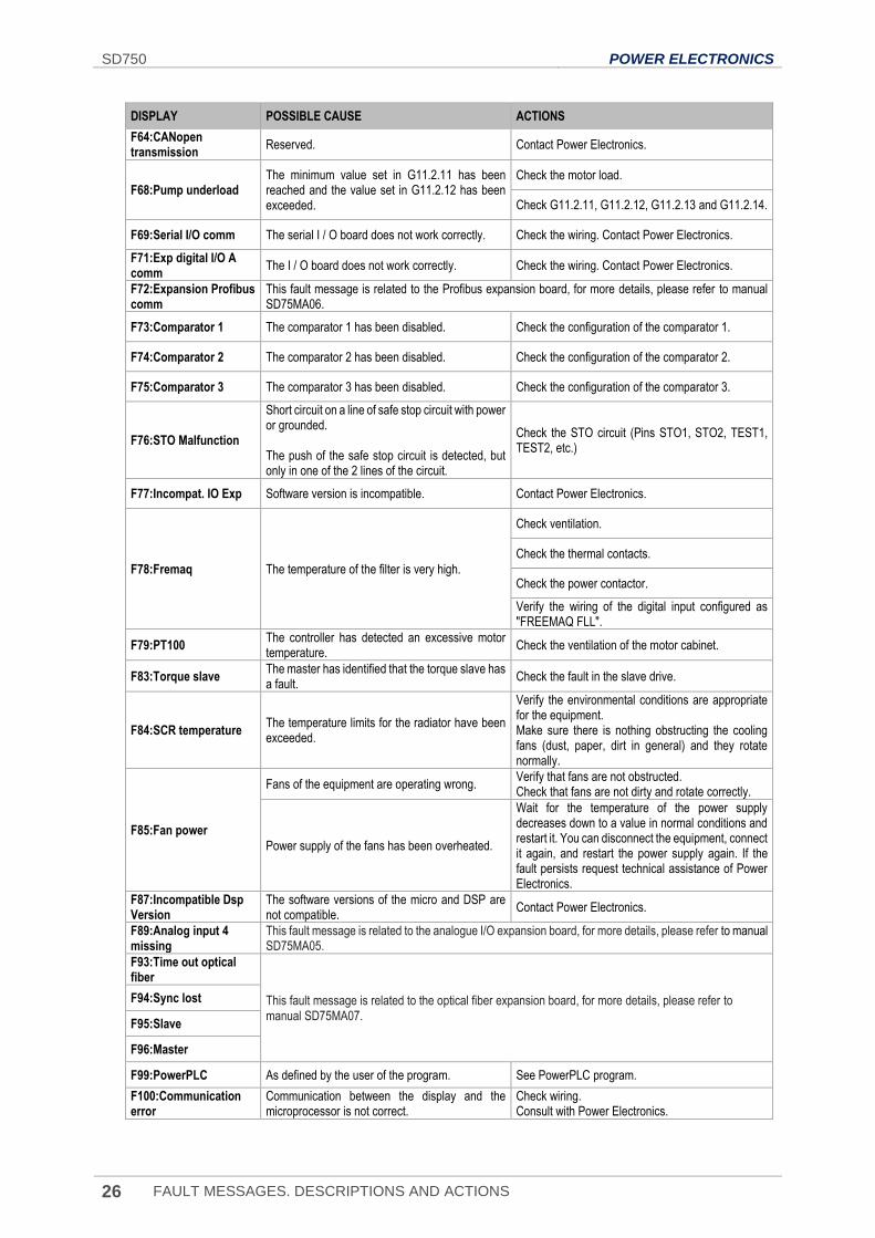
F64:CANopen transmission
Reserved. Contact Power Electronics.
F68:Pump underload The minimum value set in G11.2.11 has been reached and the value set in G11.2.12 has been exceeded.
Check the motor load.
Check G11.2.11, G11.2.12, G11.2.13 and G11.2.14.
F69:Serial I/O comm The serial I / O board does not work correctly. Check the wiring. Contact Power Electronics.
F71:Exp digital I/O A comm
The I / O board does not work correctly. Check the wiring. Contact Power Electronics.
F72:Expansion Profibus comm
This fault message is related to the Profibus expansion board, for more details, please refer to manual SD75MA06.
F73:Comparator 1 The comparator 1 has been disabled. Check the configuration of the comparator 1.
F74:Comparator 2 The comparator 2 has been disabled. Check the configuration of the comparator 2.
F75:Comparator 3 The comparator 3 has been disabled. Check the configuration of the comparator 3.
F76:STO Malfunction
Short circuit on a line of safe stop circuit with power or grounded. The push of the safe stop circuit is detected, but only in one of the 2 lines of the circuit.
Check the STO circuit (Pins STO1, STO2, TEST1, TEST2, etc.)
F77:Incompat. IO Exp Software version is incompatible. Contact Power Electronics.
F78:Fremaq The temperature of the filter is very high.
Check ventilation.
Check the thermal contacts.
Check the power contactor.
Verify the wiring of the digital input configured as "FREEMAQ FLL".
F79:PT100 The controller has detected an excessive motor temperature.
Check the ventilation of the motor cabinet.
F83:Torque slave The master has identified that the torque slave has a fault.
Check the fault in the slave drive.
F84:SCR temperature The temperature limits for the radiator have been exceeded.
Verify the environmental conditions are appropriate for the equipment. Make sure there is nothing obstructing the cooling fans (dust, paper, dirt in general) and they rotate normally.
F85:Fan power
Fans of the equipment are operating wrong. Verify that fans are not obstructed. Check that fans are not dirty and rotate correctly.
Power supply of the fans has been overheated.
Wait for the temperature of the power supply decreases down to a value in normal conditions and restart it. You can disconnect the equipment, connect it again, and restart the power supply again. If the fault persists request technical assistance of Power Electronics.
F87:Incompatible Dsp Version
The software versions of the micro and DSP are not compatible.
Contact Power Electronics.
F89:Analog input 4 missing
This fault message is related to the analogue I/O expansion board, for more details, please refer to manual SD75MA05.
F93:Time out optical fiber
This fault message is related to the optical fiber expansion board, for more details, please refer to manual SD75MA07.
F94:Sync lost
F95:Slave
F96:Master
F99:PowerPLC As defined by the user of the program. See PowerPLC program.
F100:Communication error
Communication between the display and the microprocessor is not correct.
Check wiring. Consult with Power Electronics.
POWER ELECTRONICS SD750
FAULT MESSAGES. DESCRIPTIONS AND ACTIONS 27
EN
DISPLAY POSSIBLE CAUSE ACTIONS
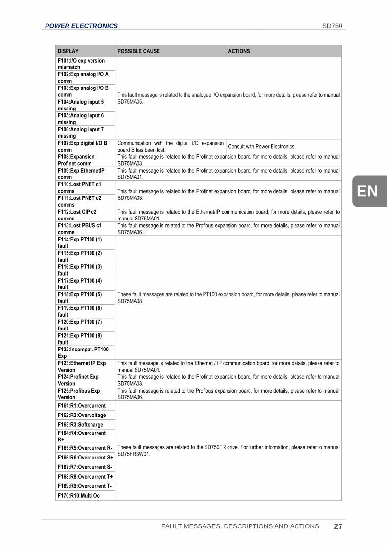
F101:I/O exp version mismatch
This fault message is related to the analogue I/O expansion board, for more details, please refer to manual SD75MA05.
F102:Exp analog I/O A comm
F103:Exp analog I/O B comm
F104:Analog input 5 missing
F105:Analog input 6 missing
F106:Analog input 7 missing
F107:Exp digital I/O B comm
Communication with the digital I/O expansion board B has been lost.
Consult with Power Electronics.
F108:Expansion Profinet comm
This fault message is related to the Profinet expansion board, for more details, please refer to manual SD75MA03.
F109:Exp EthernetIP comm
This fault message is related to the Profinet expansion board, for more details, please refer to manual SD75MA01.
F110:Lost PNET c1 comms This fault message is related to the Profinet expansion board, for more details, please refer to manual
SD75MA03. F111:Lost PNET c2 comms
F112:Lost CIP c2 comms
This fault message is related to the Ethernet/IP communication board, for more details, please refer to manual SD75MA01.
F113:Lost PBUS c1 comms
This fault message is related to the Profibus expansion board, for more details, please refer to manual SD75MA06.
F114:Exp PT100 (1) fault
These fault messages are related to the PT100 expansion board, for more details, please refer to manual SD75MA08.
F115:Exp PT100 (2) fault
F116:Exp PT100 (3) fault
F117:Exp PT100 (4) fault
F118:Exp PT100 (5) fault
F119:Exp PT100 (6) fault
F120:Exp PT100 (7) fault
F121:Exp PT100 (8) fault
F122:Incompat. PT100 Exp
F123:Ethernet IP Exp Version
This fault message is related to the Ethernet / IP communication board, for more details, please refer to manual SD75MA01.
F124:Profinet Exp Version
This fault message is related to the Profinet expansion board, for more details, please refer to manual SD75MA03.
F125:Profibus Exp Version
This fault message is related to the Profibus expansion board, for more details, please refer to manual SD75MA06.
F161:R1:Overcurrent
These fault messages are related to the SD750FR drive. For further information, please refer to manual SD75FRSW01.
F162:R2:Overvoltage
F163:R3:Softcharge
F164:R4:Overcurrent R+
F165:R5:Overcurrent R-
F166:R6:Overcurrent S+
F167:R7:Overcurrent S-
F168:R8:Overcurrent T+
F169:R9:Overcurrent T-
F170:R10:Multi Oc
SD750 POWER ELECTRONICS
28 FAULT MESSAGES. DESCRIPTIONS AND ACTIONS
DISPLAY POSSIBLE CAUSE ACTIONS
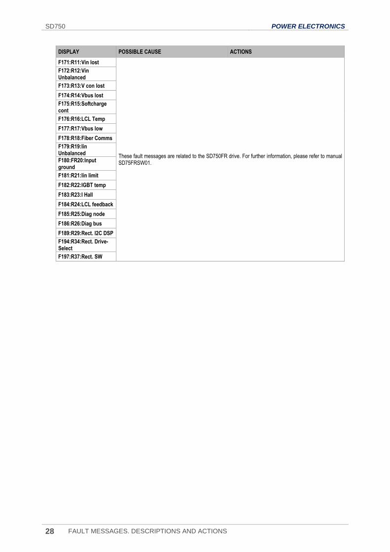
F171:R11:Vin lost
These fault messages are related to the SD750FR drive. For further information, please refer to manual SD75FRSW01.
F172:R12:Vin Unbalanced
F173:R13:V con lost
F174:R14:Vbus lost
F175:R15:Softcharge cont
F176:R16:LCL Temp
F177:R17:Vbus low
F178:R18:Fiber Comms
F179:R19:Iin Unbalanced
F180:FR20:Input ground
F181:R21:Iin limit
F182:R22:IGBT temp
F183:R23:I Hall
F184:R24:LCL feedback
F185:R25:Diag node
F186:R26:Diag bus
F189:R29:Rect. I2C DSP
F194:R34:Rect. Drive-Select
F197:R37:Rect. SW
POWER ELECTRONICS SD750
VISUALIZATION PARAMETERS 29
EN
4. VISUALIZATION PARAMETERS
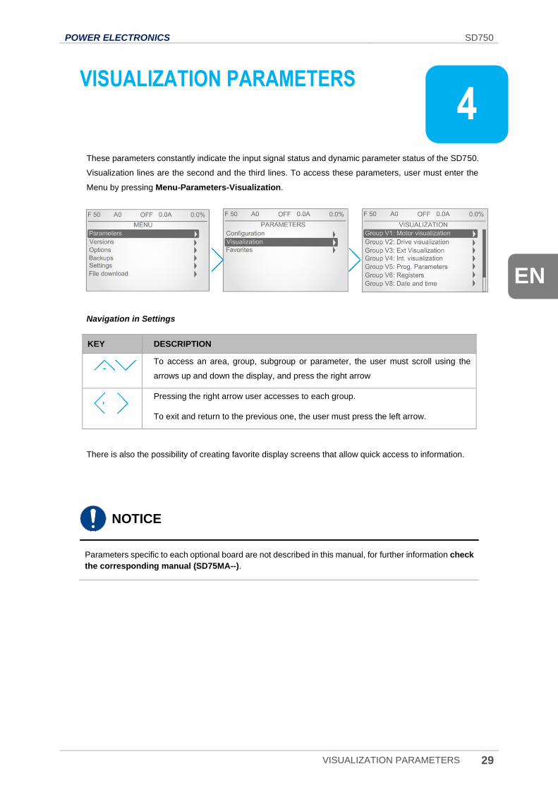
These parameters constantly indicate the input signal status and dynamic parameter status of the SD750.
Visualization lines are the second and the third lines. To access these parameters, user must enter the
Menu by pressing Menu-Parameters-Visualization.
Navigation in Settings
KEY DESCRIPTION
To access an area, group, subgroup or parameter, the user must scroll using the
arrows up and down the display, and press the right arrow
Pressing the right arrow user accesses to each group.
To exit and return to the previous one, the user must press the left arrow.
There is also the possibility of creating favorite display screens that allow quick access to information.
NOTICE
Parameters specific to each optional board are not described in this manual, for further information check
the corresponding manual (SD75MA--).
4

SD750 POWER ELECTRONICS
30 VISUALIZATION PARAMETERS
Group V1: Motor visualization
This group shows information related to motor parameters.
Note: The parameter associated with the optical fiber board (SV1.17) will only be displayed if an optical
fiber expansion board has been connected. Check document SD75MA07 for further information.
Screen Units Description
SV1.1-Speed reference = 0.0 % % Shows the present reference value of speed which is applied to the motor.
SV1.2-Torque reference = 0.0 % % Shows the present reference value of torque which is applied to the motor.
SV1.3-Motor speed (%) = 0.0 % % Shows the motor speed in percentage.
SV1.4-Motor speed (rpm) = 0 rpm rpm Shows the motor speed in revolutions per minute.
SV1.5-Motor frequency = 0.0 Hz Hz Shows the frequency being applied to the motor.
SV1.6-Motor voltage = 0 V V Shows the present voltage applied to the motor.
SV1.7-Motor current = 0.0 A A Shows the present current flowing to the motor.
SV1.8-Motor torque = 0.0 % % Shows the present torque applied to the motor.
SV1.9-Motor phi cosine = 0.85 - Shows the motor's cos phi.
SV1.10-Motor power = 0.0 kW kW Shows the instantaneous power consumption of the motor.
SV1.11.1-U motor current= 0.0 A A Shows the instantaneous current of each phase of the motor (U).
SV1.11.2-V motor current = 0.0 A A Shows the instantaneous current of each phase of the motor (V).
SV1.11.3-W motor current= 0.0 A A Shows the instantaneous current of each phase of the motor (W).
SV1.12.1-U-V motor voltage = 0.0 V V Shows the instantaneous voltage applied (UV).
SV1.12.2-V-W motor voltage = 0.0 V V Shows the instantaneous voltage applied (VW).
SV1.12.3-W-U motor voltage = 0.0 V V Shows the instantaneous voltage applied (UW).
SV1.13-PTC Status = No - Shows whether the motor PTC is connected or disconnected. Visible if [G4.1.10 = PTC].
SV1.14-Estimated. Motor temp(%) = 0.0 % % Shows the estimated motor temperature.
SV1.15-Motor temperature = 0 ºC ºC Shows the motor temperature measured with the PT100 sensor. Visible if [G4.4.0 = YES].
POWER ELECTRONICS SD750
VISUALIZATION PARAMETERS 31
EN
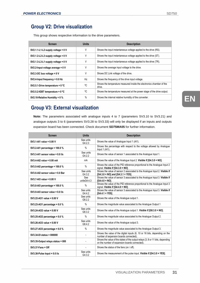
Group V2: Drive visualization
This group shows respective information to the drive parameters.
Screen Units Description
SV2.1.1-L1-L2 supply voltage = 0 V V Shows the input instantaneous voltage applied to the drive (RS).
SV2.1.2-L2-L3 supply voltage = 0 V V Shows the input instantaneous voltage applied to the drive (ST).
SV2.1.3-L3-L1 supply voltage = 0 V V Shows the input instantaneous voltage applied to the drive (TR).
SV2.2-Input voltage average = 0 V V Shows the average input voltage to the drive.
SV2.3-DC bus voltage = 0 V V Shows DC Link voltage of the drive.
SV2.4-Input frequency = 0.0 Hz Hz Shows the frequency of the drive input voltage.
SV2.5.1-Drive temperature = 0 ºC ºC Shows the temperature measured inside the electronics chamber of the drive.
SV2.5.2-IGBT temperature = 0 ºC ºC Shows the temperature measured at the power stage of the drive output.
SV2.10-Relative Humidity = 0 % % Shows the internal relative humidity of the converter.
Group V3: External visualization
Note: The parameters associated with analogue inputs 4 to 7 (parameters SV3.10 to SV3.21) and
analogue outputs 3 to 6 (parameters SV3.28 to SV3.33) will only be displayed if an inputs and outputs
expansion board has been connected. Check document SD75MA05 for further information.
Screen Units Description
SV3.1-AI1 value = 0.00 V See units
G4.2.3 Shows the value of Analogue Input 1 (AI1).
SV3.2-AI1 percentage = 100.0 % % Shows the percentage with respect to the voltage allowed by Analogue Input 1 (AI1).
SV3.3-AI1 sensor value = 0.0 l/s See units
G4.2.2 Shows the value of sensor 1 associated to the Analogue Input 1.
SV3.4-AI2 value = 0.00 mA mA Shows the value of the Analogue Input 2. Visible if [G4.3.0 = NO].
SV3.5-AI2 percentage = 100.0 % % Shows the value of the PID reference proportional to the Analogue Input 2 signal. Visible if [G4.3.0 = NO].
SV3.6-AI2 sensor value = 0.0 Bar See units
G4.3.2
Shows the value of sensor 2 associated to the Analogue Input 2. Visible if [G4.3.0 = NO] and [G4.3.1 = YES].
SV3.7-AI3 value = 0.00 V See
unitsG4.4.3 Shows the value of sensor 3 associated to the Analogue Input 3. Visible if [G4.4.0 = NO].
SV3.8-AI3 percentage = 100.0 % % Shows the value of the PID reference proportional to the Analogue Input 3 signal. Visible if [G4.4.0 = NO].
SV3.9-AI3 sensor value = 0.0 l/s See units
G4.4.2 Shows the value of sensor 3 associated to the Analogue Input 3. Visible if [G4.4.1 = YES].
SV3.22-AO1 value = 0.00 V See units
G8.2.2 Shows the value of the Analogue output 1.
SV3.23-AO1 percentage = 0.0 % % Shows the magnitude value associated to the Analogue Output 1
SV3.24-AO2 value = 0.00 V See units
G8.3.2 Shows the value of the Analogue output 1. Visible if [G8.3.0 = NO].
SV3.25-AO2 percentage = 0.0 % % Shows the magnitude value associated to the Analogue Output 2.
SV3.26-AO3 value = 0.00 V See units
G8.4.2 Shows the value of the Analogue output 3.
SV3.27-AO3 percentage = 0.0 % % Shows the magnitude value associated to the Analogue Output 3.
SV3.34-DI status = 000000 - Shows the value of the digital inputs (6, 10 or 16 bits, depending on the number of expansion boards connected).
SV3.35-Output relays status = 000 - Shows the value of the states of the output relays (3, 8 or 11 bits, depending on the number of expansion boards connected).
SV3.37-Fans = Off - Shows the status of the fans (on / off).
SV3.38-Pulse Input = 0.0 l/s See units
G4.3.2 Shows the measurement of the pulse input. Visible if [G4.3.0 = YES].
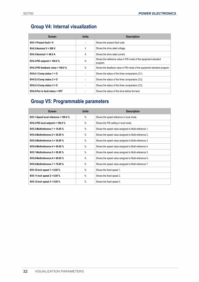
SD750 POWER ELECTRONICS
32 VISUALIZATION PARAMETERS
Group V4: Internal visualization
Screen Units Description
SV4.1-Present fault = 0 - Shows the present fault code.
SV4.2-Nominal V = 500 V V Shows the drive rated voltage.
SV4.3-Nominal I = 46.0 A A Shows the drive rated current.
SV4.4-PID setpoint = 100.0 % % Shows the reference value in PID mode of the equipment standard
program.
SV4.5-PID feedback value = 100.0 % % Shows the feedback value in PID mode of the equipment standard program.
SV4.8.1-Comp status 1 = O - Shows the status of the three comparators (C1).
SV4.8.2-Comp status 2 = O - Shows the status of the three comparators (C2).
SV4.8.3-Comp status 3 = O - Shows the status of the three comparators (C3).
SV4.9-Pior to fault status = OFF - Shows the status of the drive before the fault.
Group V5: Programmable parameters
Screen Units Description
SV5.1-Speed local reference = 100.0 % % Shows the speed reference in local mode.
SV5.2-PID local setpoint = 100.0 % % Shows the PID setting in local mode.
SV5.3-Multireference 1 = 10.00 % % Shows the speed value assigned to Multi-reference 1.
SV5.4-Multireference 2 = 20.00 % % Shows the speed value assigned to Multi-reference 2.
SV5.5-Multireference 3 = 30.00 % % Shows the speed value assigned to Multi-reference 3.
SV5.6-Multireference 4 = 40.00 % % Shows the speed value assigned to Multi-reference 4.
SV5.7-Multireference 5 = 50.00 % % Shows the speed value assigned to Multi-reference 5.
SV5.8-Multireference 6 = 60.00 % % Shows the speed value assigned to Multi-reference 6.
SV5.9-Multireference 7 = 70.00 % % Shows the speed value assigned to Multi-reference 7.
SV5.10-Inch speed 1 = 0.00 % % Shows the fixed speed 1.
SV5.11-Inch speed 2 = 0.00 % % Shows the fixed speed 2.
SV5.12-Inch speed 3 = 0.00 % % Shows the fixed speed 3.
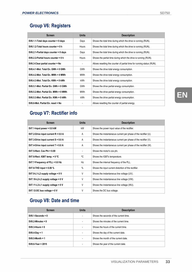
POWER ELECTRONICS SD750
VISUALIZATION PARAMETERS 33
EN
Group V6: Registers
Screen Units Description
SV6.1.1-Total days counter = 0 days Days Shows the total time during which the drive is running (RUN).
SV6.1.2-Total hours counter = 0 h Hours Shows the total time during which the drive is running (RUN).
SV6.2.1-Partial days counter = 0 days Days Shows the total time during which the drive is running (RUN).
SV6.2.2-Partial hours counter = 0 h Hours Shows the partial time during which the drive is running (RUN).
SV6.3-Clear partial counter = No - Allows resetting the counter of partial time for running status (RUN).
SV6.4.1-Mot. Total En. GWh = 0 GWh GWh Shows the drive total energy consumption.
SV6.4.2-Mot. Total En. MWh = 0 MWh MWh Shows the drive total energy consumption.
SV6.4.3-Mot. Total En. KWh = 0 kWh kWh Shows the drive total energy consumption.
SV6.5.1-Mot. Partial En. GWh = 0 GWh GWh Shows the drive partial energy consumption.
SV6.5.2-Mot. Partial En. MWh = 0 MWh MWh Shows the drive partial energy consumption.
SV6.5.3-Mot. Partial En. KWh = 0 kWh kWh Shows the drive partial energy consumption.
SV6.6-Mot. Partial En. reset = No - Allows resetting the counter of partial energy.
Group V7: Rectifier info
Screen Units Description
SV7.1-Input power = 0.0 kW kW Shows the power input value of the rectifier.
SV7.2-Drive input current R = 0.0 A A Shows the instantaneous current per phase of the rectifier (U).
SV7.3-Drive input current S = 0.0 A A Shows the instantaneous current per phase of the rectifier (V).
SV7.4-Drive input current T = 0.0 A A Shows the instantaneous current per phase of the rectifier (W).
SV7.5-Rect. Cos Phi = 0.00 - Shows the motor's cos phi.
SV7.6-Rect. IGBT temp. = 0 ºC ºC Shows the IGBTs temperature.
SV7.7-Frequency of PLL = 0.0 Hz Hz Shows the internal frequency of the PLL.
SV7.8-THD input = 0.00 % % Shows the input current distortion of the rectifier.
SV7.9-L1-L2 supply voltage = 0 V V Shows the instantaneous line voltage (UV).
SV7.10-L2-L3 supply voltage = 0 V V Shows the instantaneous line voltage (VW).
SV7.11-L3-L1 supply voltage = 0 V V Shows the instantaneous line voltage (WU).
SV7.12-DC bus voltage = 0 V V Shows the DC bus voltage.
Group V8: Date and time
Screen Units Description
SV8.1-Seconds = 0 - Shows the seconds of the current time.
SV8.2-Minutes = 0 - Shows the minutes of the current time.
SV8.3-Hours = 0 - Shows the hours of the current time.
SV8.4-Day = 1 - Shows the day of the current date.
SV8.5-Month = 1 - Shows the month of the current date.
SV8.6-Year = 2015 - Shows the year of the current date.
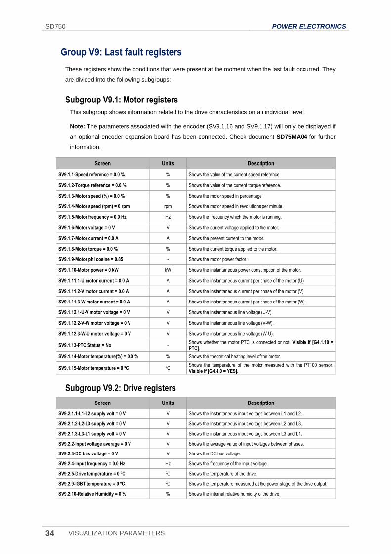
SD750 POWER ELECTRONICS
34 VISUALIZATION PARAMETERS
Group V9: Last fault registers
These registers show the conditions that were present at the moment when the last fault occurred. They
are divided into the following subgroups:
Subgroup V9.1: Motor registers
This subgroup shows information related to the drive characteristics on an individual level.
Note: The parameters associated with the encoder (SV9.1.16 and SV9.1.17) will only be displayed if
an optional encoder expansion board has been connected. Check document SD75MA04 for further
information.
Screen Units Description
SV9.1.1-Speed reference = 0.0 % % Shows the value of the current speed reference.
SV9.1.2-Torque reference = 0.0 % % Shows the value of the current torque reference.
SV9.1.3-Motor speed (%) = 0.0 % % Shows the motor speed in percentage.
SV9.1.4-Motor speed (rpm) = 0 rpm rpm Shows the motor speed in revolutions per minute.
SV9.1.5-Motor frequency = 0.0 Hz Hz Shows the frequency which the motor is running.
SV9.1.6-Motor voltage = 0 V V Shows the current voltage applied to the motor.
SV9.1.7-Motor current = 0.0 A A Shows the present current to the motor.
SV9.1.8-Motor torque = 0.0 % % Shows the current torque applied to the motor.
SV9.1.9-Motor phi cosine = 0.85 - Shows the motor power factor.
SV9.1.10-Motor power = 0 kW kW Shows the instantaneous power consumption of the motor.
SV9.1.11.1-U motor current = 0.0 A A Shows the instantaneous current per phase of the motor (U).
SV9.1.11.2-V motor current = 0.0 A A Shows the instantaneous current per phase of the motor (V).
SV9.1.11.3-W motor current = 0.0 A A Shows the instantaneous current per phase of the motor (W).
SV9.1.12.1-U-V motor voltage = 0 V V Shows the instantaneous line voltage (U-V).
SV9.1.12.2-V-W motor voltage = 0 V V Shows the instantaneous line voltage (V-W).
SV9.1.12.3-W-U motor voltage = 0 V V Shows the instantaneous line voltage (W-U).
SV9.1.13-PTC Status = No - Shows whether the motor PTC is connected or not. Visible if [G4.1.10 = PTC].
SV9.1.14-Motor temperature(%) = 0.0 % % Shows the theoretical heating level of the motor.
SV9.1.15-Motor temperature = 0 ºC ºC Shows the temperature of the motor measured with the PT100 sensor. Visible if [G4.4.0 = YES].
Subgroup V9.2: Drive registers
Screen Units Description
SV9.2.1.1-L1-L2 supply volt = 0 V V Shows the instantaneous input voltage between L1 and L2.
SV9.2.1.2-L2-L3 supply volt = 0 V V Shows the instantaneous input voltage between L2 and L3.
SV9.2.1.3-L3-L1 supply volt = 0 V V Shows the instantaneous input voltage between L3 and L1.
SV9.2.2-Input voltage average = 0 V V Shows the average value of input voltages between phases.
SV9.2.3-DC bus voltage = 0 V V Shows the DC bus voltage.
SV9.2.4-Input frequency = 0.0 Hz Hz Shows the frequency of the input voltage.
SV9.2.5-Drive temperature = 0 ºC ºC Shows the temperature of the drive.
SV9.2.9-IGBT temperature = 0 ºC ºC Shows the temperature measured at the power stage of the drive output.
SV9.2.10-Relative Humidity = 0 % % Shows the internal relative humidity of the drive.

POWER ELECTRONICS SD750
VISUALIZATION PARAMETERS 35
EN
Subgroup V9.3: External registers
Note: The parameters associated with analogue inputs 4 to 7 (parameters SV9.3.10 to SV9.3.21) and
analogue outputs 3 to 6 (parameters SV9.3.28 to SV9.3.33) will only be displayed if an inputs and
outputs expansion board has been connected. Check document SD75MA05 for further information.
Screen Units Description
SV9.3.1-AI1 value = 0.00 V V Shows the average value of the analogue input 1.
SV9.3.2-AI1 percentage = 100.0 % % Shows the speed reference or the PID proportional setting for the analogue input 1.
SV9.3.3-AI1 sensor value = 0.0 l/s l/s Shows the value of sensor 1 associated with analogue input 1.
SV9.3.4-AI2 value = 0.00 mA mA Shows the average value of the analogue input 2.
SV9.3.5-AI2 percentage = 100.0 % % Shows the speed reference or the PID proportional setting for the analogue input 2.
SV9.3.6-AI2 sensor value = 0.0 Bar Bar Shows the value of sensor 1 associated with analogue input 2.
SV9.3.7-AI3 value = 0.00 V See units G4.4.3 Shows the average value of the analogue input 3.
SV9.3.8-AI3 percentage = 100.0 % % Shows the speed reference or the PID proportional setting for the analogue input 3.
SV9.3.9-AI3 sensor value = 0.0 l/s See units G4.4.2 Shows the value of sensor 1 associated with analogue input 3.
SV9.3.22-AO1 value = 0.00 V See units G8.2.2 Shows the value of analogue output 1.
SV9.3.23-AO1 percentage = 0.0 % % Shows the value of sensor 1 associated with analogue output 1.
SV9.3.24-AO2 value = 0.00 V See units G8.3.2 Shows the value of analogue output 2.
SV9.3.25-AO2 percentage = 0.0 % % Shows the value of sensor 1 associated with analogue output 2.
SV9.3.26-AO3 value = 0.00 V See units G8.4.2 Shows the value of analogue output 3.
SV9.3.27-AO3 percentage = 0.0 % % Shows the value of sensor 1 associated with analogue output 3.
SV9.3.34-DI status = 000000 -
Shows the status of each of the digital inputs of the central control: 6, 10 or 16 bits (input 1: first from the left).
SV9.3.34-DI status = 00000000000 -
SV9.3.34-DI status = 0000000000000000 -
SV9.3.35-DO status = 000 -
Shows the status of digital outputs: 3, 8 or 11 bits (entry 1: first from the left). Note: Only displayed if an expansion board has been connected. If there are two expansion boards connected, 16 bits will be displayed.
SV9.3.35-DO status = 00000000 -
SV9.3.35-DO status = 0000000000000 -
Subgroup V9.4: Internal registers
Screen Units Description
SV9.4.1-Last fault = 0 - Shows the present fault code.
SV9.4.2-Drive nominal current = 46.0 A A Shows the rated current of the drive.
SV9.4.3-Drive nominal voltage = 500 V V Shows the rated voltage of the drive.
SV9.4.6-PID setpoint = 100.0 % % Shows the setpoint value of the PID of the standard equipment program.
SV9.4.7-PID feedback value = 100.0 % % Shows the PID feedback value of the standard equipment program.
SV9.4.8.1-Comp status 1 = O - Shows the status of the three comparators (C1).
SV9.4.8.2-Comp status 2 = O - Shows the status of the three comparators (C2).
SV9.4.8.3-Comp status 3 = O - Shows the status of the three comparators (C3).
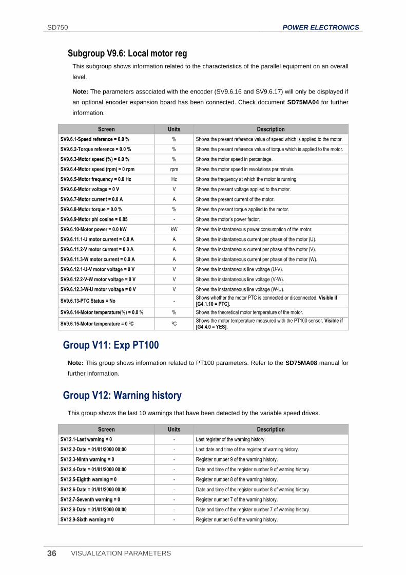
SD750 POWER ELECTRONICS
36 VISUALIZATION PARAMETERS
Subgroup V9.6: Local motor reg
This subgroup shows information related to the characteristics of the parallel equipment on an overall
level.
Note: The parameters associated with the encoder (SV9.6.16 and SV9.6.17) will only be displayed if
an optional encoder expansion board has been connected. Check document SD75MA04 for further
information.
Screen Units Description
SV9.6.1-Speed reference = 0.0 % % Shows the present reference value of speed which is applied to the motor.
SV9.6.2-Torque reference = 0.0 % % Shows the present reference value of torque which is applied to the motor.
SV9.6.3-Motor speed (%) = 0.0 % % Shows the motor speed in percentage.
SV9.6.4-Motor speed (rpm) = 0 rpm rpm Shows the motor speed in revolutions per minute.
SV9.6.5-Motor frequency = 0.0 Hz Hz Shows the frequency at which the motor is running.
SV9.6.6-Motor voltage = 0 V V Shows the present voltage applied to the motor.
SV9.6.7-Motor current = 0.0 A A Shows the present current of the motor.
SV9.6.8-Motor torque = 0.0 % % Shows the present torque applied to the motor.
SV9.6.9-Motor phi cosine = 0.85 - Shows the motor’s power factor.
SV9.6.10-Motor power = 0.0 kW kW Shows the instantaneous power consumption of the motor.
SV9.6.11.1-U motor current = 0.0 A A Shows the instantaneous current per phase of the motor (U).
SV9.6.11.2-V motor current = 0.0 A A Shows the instantaneous current per phase of the motor (V).
SV9.6.11.3-W motor current = 0.0 A A Shows the instantaneous current per phase of the motor (W).
SV9.6.12.1-U-V motor voltage = 0 V V Shows the instantaneous line voltage (U-V).
SV9.6.12.2-V-W motor voltage = 0 V V Shows the instantaneous line voltage (V-W).
SV9.6.12.3-W-U motor voltage = 0 V V Shows the instantaneous line voltage (W-U).
SV9.6.13-PTC Status = No - Shows whether the motor PTC is connected or disconnected. Visible if [G4.1.10 = PTC].
SV9.6.14-Motor temperature(%) = 0.0 % % Shows the theoretical motor temperature of the motor.
SV9.6.15-Motor temperature = 0 ºC ºC Shows the motor temperature measured with the PT100 sensor. Visible if [G4.4.0 = YES].
Group V11: Exp PT100
Note: This group shows information related to PT100 parameters. Refer to the SD75MA08 manual for
further information.
Group V12: Warning history
This group shows the last 10 warnings that have been detected by the variable speed drives.
Screen Units Description
SV12.1-Last warning = 0 - Last register of the warning history.
SV12.2-Date = 01/01/2000 00:00 - Last date and time of the register of warning history.
SV12.3-Ninth warning = 0 - Register number 9 of the warning history.
SV12.4-Date = 01/01/2000 00:00 - Date and time of the register number 9 of warning history.
SV12.5-Eighth warning = 0 - Register number 8 of the warning history.
SV12.6-Date = 01/01/2000 00:00 - Date and time of the register number 8 of warning history.
SV12.7-Seventh warning = 0 - Register number 7 of the warning history.
SV12.8-Date = 01/01/2000 00:00 - Date and time of the register number 7 of warning history.
SV12.9-Sixth warning = 0 - Register number 6 of the warning history.
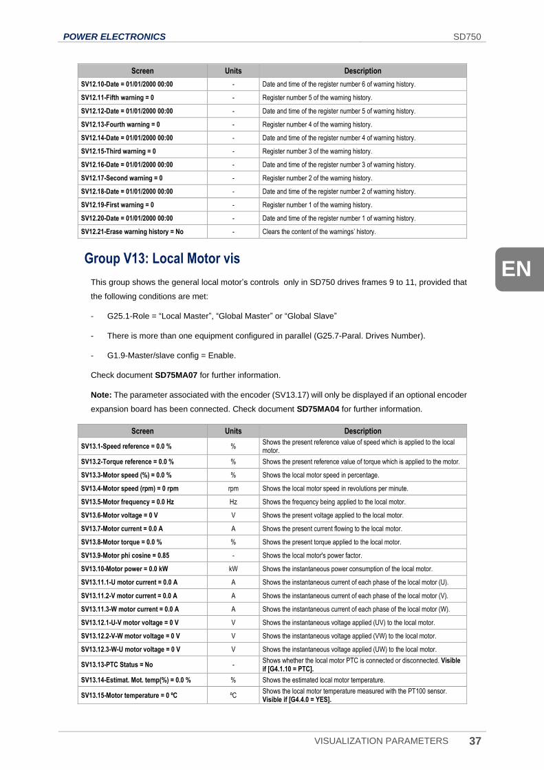
POWER ELECTRONICS SD750
VISUALIZATION PARAMETERS 37
EN
Screen Units Description
SV12.10-Date = 01/01/2000 00:00 - Date and time of the register number 6 of warning history.
SV12.11-Fifth warning = 0 - Register number 5 of the warning history.
SV12.12-Date = 01/01/2000 00:00 - Date and time of the register number 5 of warning history.
SV12.13-Fourth warning = 0 - Register number 4 of the warning history.
SV12.14-Date = 01/01/2000 00:00 - Date and time of the register number 4 of warning history.
SV12.15-Third warning = 0 - Register number 3 of the warning history.
SV12.16-Date = 01/01/2000 00:00 - Date and time of the register number 3 of warning history.
SV12.17-Second warning = 0 - Register number 2 of the warning history.
SV12.18-Date = 01/01/2000 00:00 - Date and time of the register number 2 of warning history.
SV12.19-First warning = 0 - Register number 1 of the warning history.
SV12.20-Date = 01/01/2000 00:00 - Date and time of the register number 1 of warning history.
SV12.21-Erase warning history = No - Clears the content of the warnings’ history.
Group V13: Local Motor vis
This group shows the general local motor’s controls only in SD750 drives frames 9 to 11, provided that
the following conditions are met:
- G25.1-Role = “Local Master”, “Global Master” or “Global Slave”
- There is more than one equipment configured in parallel (G25.7-Paral. Drives Number).
- G1.9-Master/slave config = Enable.
Check document SD75MA07 for further information.
Note: The parameter associated with the encoder (SV13.17) will only be displayed if an optional encoder
expansion board has been connected. Check document SD75MA04 for further information.
Screen Units Description
SV13.1-Speed reference = 0.0 % % Shows the present reference value of speed which is applied to the local motor.
SV13.2-Torque reference = 0.0 % % Shows the present reference value of torque which is applied to the motor.
SV13.3-Motor speed (%) = 0.0 % % Shows the local motor speed in percentage.
SV13.4-Motor speed (rpm) = 0 rpm rpm Shows the local motor speed in revolutions per minute.
SV13.5-Motor frequency = 0.0 Hz Hz Shows the frequency being applied to the local motor.
SV13.6-Motor voltage = 0 V V Shows the present voltage applied to the local motor.
SV13.7-Motor current = 0.0 A A Shows the present current flowing to the local motor.
SV13.8-Motor torque = 0.0 % % Shows the present torque applied to the local motor.
SV13.9-Motor phi cosine = 0.85 - Shows the local motor's power factor.
SV13.10-Motor power = 0.0 kW kW Shows the instantaneous power consumption of the local motor.
SV13.11.1-U motor current = 0.0 A A Shows the instantaneous current of each phase of the local motor (U).
SV13.11.2-V motor current = 0.0 A A Shows the instantaneous current of each phase of the local motor (V).
SV13.11.3-W motor current = 0.0 A A Shows the instantaneous current of each phase of the local motor (W).
SV13.12.1-U-V motor voltage = 0 V V Shows the instantaneous voltage applied (UV) to the local motor.
SV13.12.2-V-W motor voltage = 0 V V Shows the instantaneous voltage applied (VW) to the local motor.
SV13.12.3-W-U motor voltage = 0 V V Shows the instantaneous voltage applied (UW) to the local motor.
SV13.13-PTC Status = No - Shows whether the local motor PTC is connected or disconnected. Visible if [G4.1.10 = PTC].
SV13.14-Estimat. Mot. temp(%) = 0.0 % % Shows the estimated local motor temperature.
SV13.15-Motor temperature = 0 ºC ºC Shows the local motor temperature measured with the PT100 sensor. Visible if [G4.4.0 = YES].
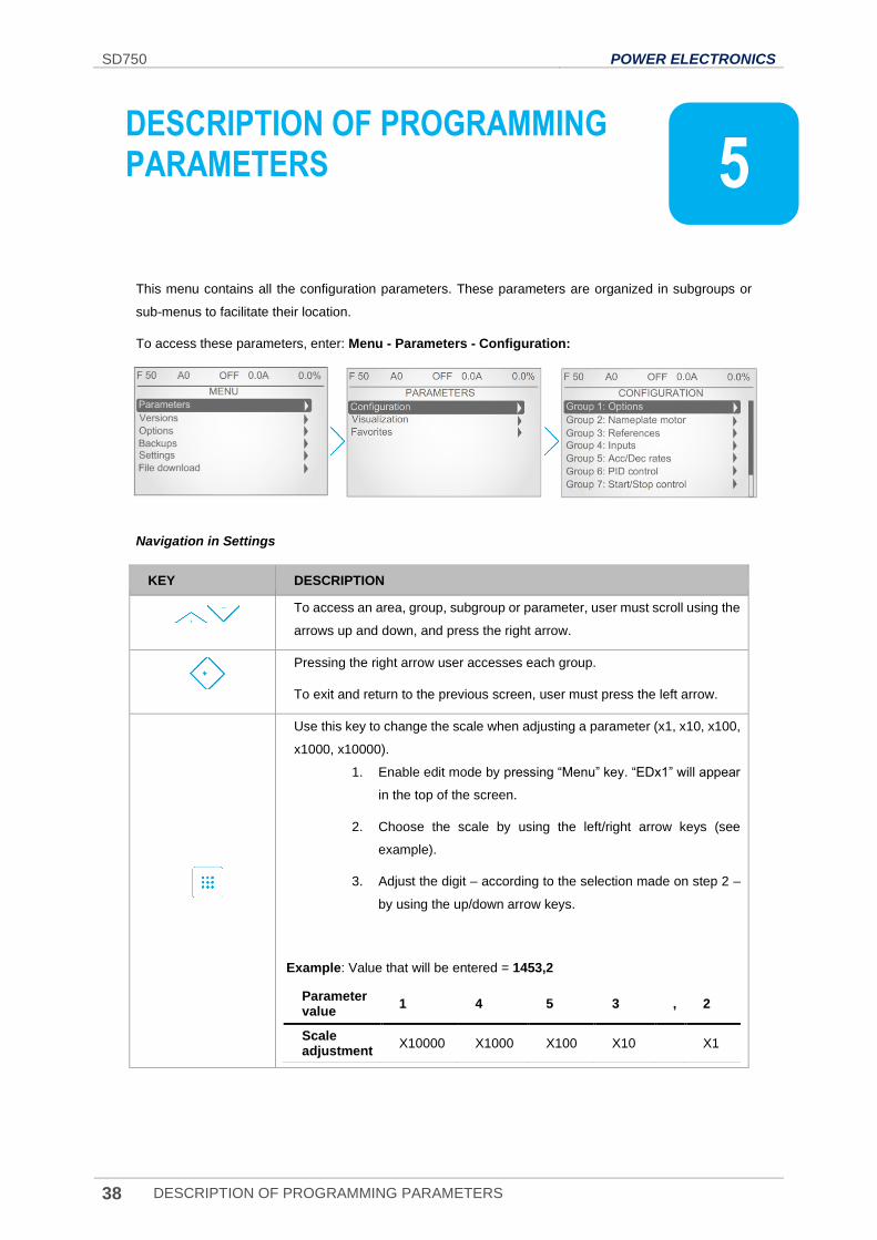
SD750 POWER ELECTRONICS
38 DESCRIPTION OF PROGRAMMING PARAMETERS
5. DESCRIPTION OF PROGRAMMING PARAMETERS
This menu contains all the configuration parameters. These parameters are organized in subgroups or
sub-menus to facilitate their location.
To access these parameters, enter: Menu - Parameters - Configuration:
Navigation in Settings
KEY DESCRIPTION
To access an area, group, subgroup or parameter, user must scroll using the
arrows up and down, and press the right arrow.
Pressing the right arrow user accesses each group.
To exit and return to the previous screen, user must press the left arrow.
Use this key to change the scale when adjusting a parameter (x1, x10, x100,
x1000, x10000).
1. Enable edit mode by pressing “Menu” key. “EDx1” will appear
in the top of the screen.
2. Choose the scale by using the left/right arrow keys (see
example).
3. Adjust the digit – according to the selection made on step 2 –
by using the up/down arrow keys.
Example: Value that will be entered = 1453,2
Parameter value
1 4 5 3 , 2
Scale adjustment
X10000 X1000 X100 X10 X1
5
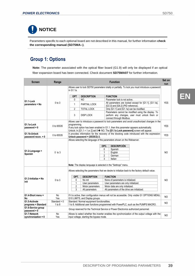
POWER ELECTRONICS SD750
DESCRIPTION OF PROGRAMMING PARAMETERS 39
EN
NOTICE
Parameters specific to each optional board are not described in this manual, for further information check
the corresponding manual (SD75MA--).
Group 1: Options
Note: The parameter associated with the optical fiber board (G1.9) will only be displayed if an optical
fiber expansion board has been connected. Check document SD75MA07 for further information.
Screen Range Function Set on
run
G1.1-Lock parameters = No
0 to 3
Allows user to lock SD750 parameters totally or partially. To lock you must introduce a password in G1.1a.
OPT DESCRIPTION FUNCTION
0 NO Parameter lock is not active.
1 PARTIAL LOCK All parameters are locked except for [G1.1], [G1.1a], [G3.3] and [G6.2] (PID reference).
2 TOTAL LOCK Only [G1.1] and [G1.1a] can be modified.
3 DISP LOCK Parameters cannot be modified using the display. To perform any changes, user must unlock them or connect through Modbus.
YES
G1.1a-Lock password = 0
0 to 65535
Allows user to introduce a password to lock parameters and avoid unauthorized changes in the programming. If any lock option has been enabled in G1.1, then this parameter appears automatically. Unlock: In [G1.1 = 1 or 2] set 0 NO. The [G1.1a Lock password] screen will appear.
YES
G1.1b-Unlock password recov. = 0
0 to 65535 It provides information for the recovery of the blocking code introduced with the expression: Unlock password = (XXXX/2)-3.
YES
G1.2-Language = Spanish
0 to 3
Allows selecting the language of the parameters shown on the Webserver.
OPC. DESCRIPCIÓN
0 Spanish
1 English
2 German
3 Italian
Note: The display language is selected in the "Settings" menu.
NO
G1.3-Initialize = No init
0 to 3
Allows selecting the parameters that we desire to initialize back to the factory default value.
OPT. DESCRIPTION FUNCTION
0 No init None of parameters is initialized.
1 User parameters User parameters are only initialized.
2 Motor parameters Motor data are only initialized.
3 All parameters All parameters of the drive are initialized.
NO
G1.4-Short menu = No
No Yes
If it is active, then configuration menus will not be accessible. Only visible G1 OPTIONS MENU, G10 LIMITS, and Display groups.
NO
G1.5-Activate programs = Standard
Standard = 0 1 to 8
Standard: Normal equipment functionalities. 1 to 8: Additional user functions programmed with PowerPLC, such as the PUMPS MACRO.
NO
G1.6-Service group password = 0
Group reserved for the Technical Service or Power Electronics authorized personnel.
G1.7-Network synchronization = 0
No Yes
Allows to select whether the inverter enables the synchronization of the output voltage with the input voltage, starting the bypass mode.
NO
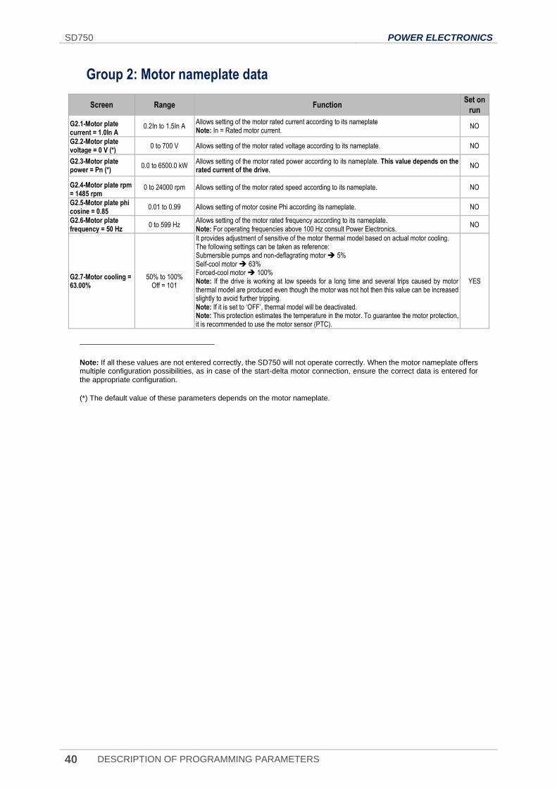
SD750 POWER ELECTRONICS
40 DESCRIPTION OF PROGRAMMING PARAMETERS
Group 2: Motor nameplate data
Screen Range Function Set on
run
G2.1-Motor plate current = 1.0In A
0.2In to 1.5In A Allows setting of the motor rated current according to its nameplate Note: In = Rated motor current.
NO
G2.2-Motor plate voltage = 0 V (*)
0 to 700 V Allows setting of the motor rated voltage according to its nameplate. NO
G2.3-Motor plate power = Pn (*)
0.0 to 6500.0 kW Allows setting of the motor rated power according to its nameplate. This value depends on the rated current of the drive.
NO
G2.4-Motor plate rpm = 1485 rpmNota:
0 to 24000 rpm Allows setting of the motor rated speed according to its nameplate. NO
G2.5-Motor plate phi cosine = 0.85
0.01 to 0.99 Allows setting of motor cosine Phi according its nameplate. NO
G2.6-Motor plate frequency = 50 Hz
0 to 599 Hz Allows setting of the motor rated frequency according to its nameplate. Note: For operating frequencies above 100 Hz consult Power Electronics.
NO
G2.7-Motor cooling = 63.00%
50% to 100% Off = 101
It provides adjustment of sensitive of the motor thermal model based on actual motor cooling. The following settings can be taken as reference: Submersible pumps and non-deflagrating motor 5% Self-cool motor 63% Forced-cool motor 100% Note: If the drive is working at low speeds for a long time and several trips caused by motor thermal model are produced even though the motor was not hot then this value can be increased slightly to avoid further tripping. Note: If it is set to ‘OFF’, thermal model will be deactivated. Note: This protection estimates the temperature in the motor. To guarantee the motor protection, it is recommended to use the motor sensor (PTC).
YES
Note: If all these values are not entered correctly, the SD750 will not operate correctly. When the motor nameplate offers multiple configuration possibilities, as in case of the start-delta motor connection, ensure the correct data is entered for the appropriate configuration.
(*) The default value of these parameters depends on the motor nameplate.
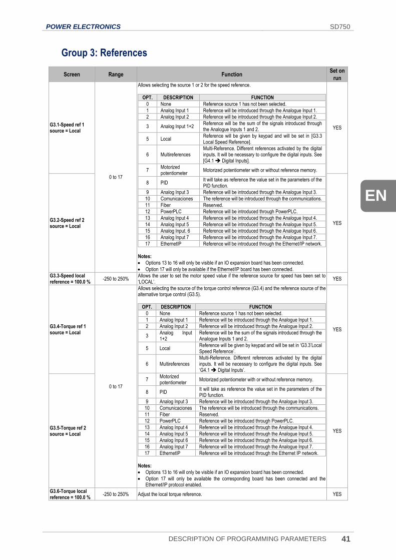
POWER ELECTRONICS SD750
DESCRIPTION OF PROGRAMMING PARAMETERS 41
EN
Group 3: References
Screen Range Function Set on
run
G3.1-Speed ref 1 source = Local
0 to 17
Allows selecting the source 1 or 2 for the speed reference.
OPT. DESCRIPTION FUNCTION
0 None Reference source 1 has not been selected.
1 Analog Input 1 Reference will be introduced through the Analogue Input 1.
2 Analog Input 2 Reference will be introduced through the Analogue Input 2.
3 Analog Input 1+2 Reference will be the sum of the signals introduced through the Analogue Inputs 1 and 2.
5 Local Reference will be given by keypad and will be set in [G3.3 Local Speed Reference].
6 Multireferences Multi-Reference. Different references activated by the digital inputs. It will be necessary to configure the digital inputs. See [G4.1 Digital Inputs].
7 Motorized potentiometer
Motorized potentiometer with or without reference memory.
8 PID It will take as reference the value set in the parameters of the PID function.
9 Analog Input 3 Reference will be introduced through the Analogue Input 3.
10 Comunicaciones The reference will be introduced through the communications.
11 Fiber Reserved.
12 PowerPLC Reference will be introduced through PowerPLC.
13 Analog Input 4 Reference will be introduced through the Analogue Input 4.
14 Analog Input 5 Reference will be introduced through the Analogue Input 5.
15 Analog Input. 6 Reference will be introduced through the Analogue Input 6.
16 Analog Input 7 Reference will be introduced through the Analogue Input 7.
17 EthernetIP Reference will be introduced through the Ethernet/IP network.
Notes:
• Options 13 to 16 will only be visible if an IO expansion board has been connected.
• Option 17 will only be available if the Ethernet/IP board has been connected.
YES
G3.2-Speed ref 2 source = Local
YES
G3.3-Speed local reference = 100.0 %
-250 to 250% Allows the user to set the motor speed value if the reference source for speed has been set to ‘LOCAL’.
YES
G3.4-Torque ref 1 source = Local
0 to 17
Allows selecting the source of the torque control reference (G3.4) and the reference source of the alternative torque control (G3.5).
OPT. DESCRIPTION FUNCTION
0 None Reference source 1 has not been selected.
1 Analog Input 1 Reference will be introduced through the Analogue Input 1.
2 Analog Input 2 Reference will be introduced through the Analogue Input 2.
3 Analog Input 1+2
Reference will be the sum of the signals introduced through the Analogue Inputs 1 and 2.
5 Local Reference will be given by keypad and will be set in ‘G3.3’Local Speed Reference’.
6 Multireferences Multi-Reference. Different references activated by the digital inputs. It will be necessary to configure the digital inputs. See ‘G4.1 Digital Inputs’.
7 Motorized potentiometer
Motorized potentiometer with or without reference memory.
8 PID It will take as reference the value set in the parameters of the PID function.
9 Analog Input 3 Reference will be introduced through the Analogue Input 3.
10 Comunicaciones The reference will be introduced through the communications.
11 Fiber Reserved.
12 PowerPLC Reference will be introduced through PowerPLC.
13 Analog Input 4 Reference will be introduced through the Analogue Input 4.
14 Analog Input 5 Reference will be introduced through the Analogue Input 5.
15 Analog Input 6 Reference will be introduced through the Analogue Input 6.
16 Analog Input 7 Reference will be introduced through the Analogue Input 7.
17 EthernetIP Reference will be introduced through the Ethernet IP network.
Notes:
• Options 13 to 16 will only be visible if an IO expansion board has been connected.
• Option 17 will only be available the corresponding board has been connected and the Ethernet/IP protocol enabled.
YES
G3.5-Torque ref 2 source = Local
YES
G3.6-Torque local reference = 100.0 %
-250 to 250% Adjust the local torque reference. YES
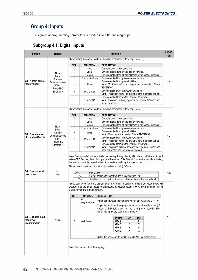
SD750 POWER ELECTRONICS
42 DESCRIPTION OF PROGRAMMING PARAMETERS
Group 4: Inputs
This group of programming parameters is divided into different subgroups.
Subgroup 4.1: Digital inputs
Screen Range Function Set on
run
G4.1.1-Main control mode = Local
None
Local Remote
Communications
Fiber PowerPLC EthernetIP
Allows setting the control mode for the drive commands (Start/Stop, Reset, ...)
OPT. FUNCTION DESCRIPTION
0 None Control mode 1 is not operative.
1 Local Drive control is done by the display keypad.
2 Remote Drive controlled through digital inputs of the control terminals.
3 Communications Drive controlled through communication bus.
4 Fiber Drive controlled through optical fiber Note: [G1.9 Master/slave config] must be enabled. Check SD75MA07.
5 PowerPLC Drive controlled with the PowerPLC macro. Note: This option will not be available if the macro is disabled.
6 EthernetIP Drive controlled through the Ethernet IP network. Note: This option will only appear if an Ethernet/IP board has been connected.
NO
G4.1.2-Alternative ctrl mode = Remote
None
Local Remote
Communications
Fiber PowerPLC EthernetIP
Allows setting the control mode for the drive commands (Start/Stop, Reset, ...).
OPT. FUNCTION DESCRIPTION
0 None Control mode 2 is not operative.
1 Local Drive control is done by the display keypad.
2 Remote Drive controlled through digital inputs of the control terminals.
3 Communications Drive controlled through communication bus.
4 Fiber Drive controlled through optical fiber Note: When the role is master. Check SD75MA07.
5 PowerPLC Drive controlled with the PowerPLC macro. Note: This option will not be available if the macro is disabled.
6 EthernetIP Drive controlled through the Ethernet IP network. Note: This option will only appear if the Ethernet/IP board has been connected and the protocol enabled.
Note: Control mode 2 will be activated exclusively through the digital inputs and with the equipment set on OFF. For this, the digital input must be set to 17 Control 2. When the input is activated, the auxiliary control mode will enter into operation, inhibiting the main mode.
NO
G4.1.3-Allow local reset = Yes
No Yes
Allows user to reset faults from the display keypad unit (LOCAL).
OPT. FUNCTION
No It is not possible to reset from the display keypad unit.
Yes The drive can be reset via the reset button on the display keypad unit.
YES
G4.1.4-Digital input mode = All programmable
1 to 5
Allows user to configure the digital inputs for different functions. All options described below will program to all the digital inputs simultaneously, except for option ‘1 All Programmable’, which allows configuring them separately.
OPT. FUNCTION DESCRIPTION
1 All programmable
Inputs configuration individually by user. See G4.1.5 to G4.1.10.
2 Mref 2 wires
Digital inputs 4 and 5 are programmed as multiple references (of speed or PID references) for up to 4 preset speeds. The remaining inputs are user programmable.
PARM DI4 DI5
G14.4 0 0
G14.5 0 X
G14.6 X 0
G14.7 X X
Note: It is necessary to set G3.1 or G3.2 to “Multireferences”.
Note: Continues in the following page.
NO
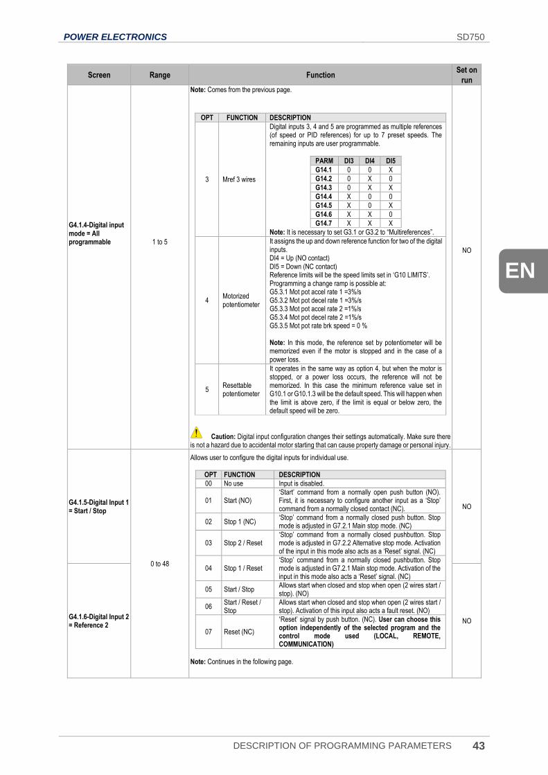
POWER ELECTRONICS SD750
DESCRIPTION OF PROGRAMMING PARAMETERS 43
EN
Screen Range Function Set on
run G4.1.4-Digital input mode = All programmable
1 to 5
Note: Comes from the previous page.
OPT FUNCTION DESCRIPTION
3 Mref 3 wires
Digital inputs 3, 4 and 5 are programmed as multiple references (of speed or PID references) for up to 7 preset speeds. The remaining inputs are user programmable.
PARM DI3 DI4 DI5
G14.1 0 0 X
G14.2 0 X 0
G14.3 0 X X
G14.4 X 0 0
G14.5 X 0 X
G14.6 X X 0
G14.7 X X X
Note: It is necessary to set G3.1 or G3.2 to “Multireferences”.
4 Motorized potentiometer
It assigns the up and down reference function for two of the digital inputs. DI4 = Up (NO contact) DI5 = Down (NC contact) Reference limits will be the speed limits set in ‘G10 LIMITS’. Programming a change ramp is possible at: G5.3.1 Mot pot accel rate 1 =3%/s G5.3.2 Mot pot decel rate 1 =3%/s G5.3.3 Mot pot accel rate 2 =1%/s G5.3.4 Mot pot decel rate 2 =1%/s G5.3.5 Mot pot rate brk speed = 0 % Note: In this mode, the reference set by potentiometer will be memorized even if the motor is stopped and in the case of a power loss.
5 Resettable potentiometer
It operates in the same way as option 4, but when the motor is stopped, or a power loss occurs, the reference will not be memorized. In this case the minimum reference value set in G10.1 or G10.1.3 will be the default speed. This will happen when the limit is above zero, if the limit is equal or below zero, the default speed will be zero.
Caution: Digital input configuration changes their settings automatically. Make sure there
is not a hazard due to accidental motor starting that can cause property damage or personal injury.
NO
G4.1.5-Digital Input 1 = Start / Stop
0 to 48
Allows user to configure the digital inputs for individual use.
OPT FUNCTION DESCRIPTION
00 No use Input is disabled.
01 Start (NO) ‘Start’ command from a normally open push button (NO). First, it is necessary to configure another input as a ‘Stop’ command from a normally closed contact (NC).
02 Stop 1 (NC) ‘Stop’ command from a normally closed push button. Stop mode is adjusted in G7.2.1 Main stop mode. (NC)
03 Stop 2 / Reset ‘Stop’ command from a normally closed pushbutton. Stop mode is adjusted in G7.2.2 Alternative stop mode. Activation of the input in this mode also acts as a ‘Reset’ signal. (NC)
04 Stop 1 / Reset ‘Stop’ command from a normally closed pushbutton. Stop mode is adjusted in G7.2.1 Main stop mode. Activation of the input in this mode also acts a ‘Reset’ signal. (NC)
05 Start / Stop Allows start when closed and stop when open (2 wires start / stop). (NO)
06 Start / Reset / Stop
Allows start when closed and stop when open (2 wires start / stop). Activation of this input also acts a fault reset. (NO)
07 Reset (NC)
‘Reset’ signal by push button. (NC). User can choose this option independently of the selected program and the control mode used (LOCAL, REMOTE, COMMUNICATION)
Note: Continues in the following page.
NO
G4.1.6-Digital Input 2 = Reference 2
NO
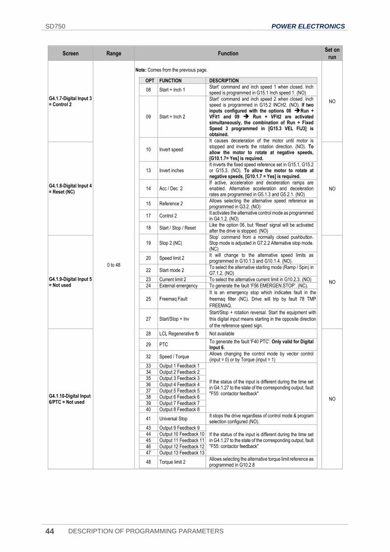
SD750 POWER ELECTRONICS
44 DESCRIPTION OF PROGRAMMING PARAMETERS
Screen Range Function Set on
run
G4.1.7-Digital Input 3 = Control 2
0 to 48
Note: Comes from the previous page.
OPT FUNCTION DESCRIPTION
08 Start + Inch 1 Start’ command and inch speed 1 when closed. Inch speed is programmed in G15.1 Inch speed 1. (NO)
09 Start + Inch 2
Start’ command and inch speed 2 when closed. Inch speed is programmed in G15.2 INCH2. (NO). If two inputs configured with the options 08 Run + VFit1 and 09 Run + VFit2 are activated simultaneously, the combination of Run + Fixed Speed 3 programmed in [G15.3 VEL FIJ3] is obtained.
10 Invert speed
It causes deceleration of the motor until motor is stopped and inverts the rotation direction. (NO). To allow the motor to rotate at negative speeds, [G10.1.7= Yes] is required.
13 Invert inches It inverts the fixed speed reference set in G15.1, G15.2 or G15.3. (NO). To allow the motor to rotate at negative speeds, [G10.1.7 = Yes] is required.
14 Acc / Dec 2 If active, acceleration and deceleration ramps are enabled. Alternative acceleration and deceleration rates are programmed in G5.1.3 and G5.2.1. (NO)
15 Reference 2 Allows selecting the alternative speed reference as programmed in G3.2. (NO)
17 Control 2 It activates the alternative control mode as programmed in G4.1.2. (NO)
18 Start / Stop / Reset Like the option 06, but ‘Reset’ signal will be activated after the drive is stopped. (NO)
19 Stop 2 (NC) Stop’ command from a normally closed pushbutton. Stop mode is adjusted in G7.2.2 Alternative stop mode. (NC)
20 Speed limit 2 It will change to the alternative speed limits as programmed in G10.1.3 and G10.1.4. (NO).
22 Start mode 2 To select the alternative starting mode (Ramp / Spin) in G7.1.2. (NO)
23 Current limit 2 To select the alternative current limit in G10.2.3. (NO)
24 External emergency To generate the fault ‘F56 EMERGEN.STOP’. (NC).
25 Freemaq Fault
It is an emergency stop which indicates fault in the
freemaq filter (NC). Drive will trip by fault 78 TMP
FREEMAQ.
27 Start/Stop + Inv
Start/Stop + rotation reversal. Start the equipment with
this digital input means starting in the opposite direction
of the reference speed sign.
28 LCL Regenerative fb Not available
29 PTC To generate the fault 'F40 PTC'. Only valid for Digital Input 6.
32 Speed / Torque Allows changing the control mode by vector control (input = 0) or by Torque (input = 1)
33 Output 1 Feedback 1
If the status of the input is different during the time set in G4.1.27 to the state of the corresponding output, fault "F55: contactor feedback"
34 Output 2 Feedback 2
35 Output 3 Feedback 3
36 Output 4 Feedback 4
37 Output 5 Feedback 5
38 Output 6 Feedback 6
39 Output 7 Feedback 7
40 Output 8 Feedback 8
41 Universal Stop It stops the drive regardless of control mode & program selection configured (NO).
43 Output 9 Feedback 9
If the status of the input is different during the time set in G4.1.27 to the state of the corresponding output, fault "F55: contactor feedback"
44 Output 10 Feedback 10
45 Output 11 Feedback 11
46 Output 12 Feedback 12
47 Output 13 Feedback 13
48 Torque limit 2 Allows selecting the alternative torque limit reference as programmed in G10.2.8
NO
G4.1.8-Digital Input 4 = Reset (NC)
NO
G4.1.9-Digital Input 5 = Not used
NO
G4.1.10-Digital Input 6/PTC = Not used
NO
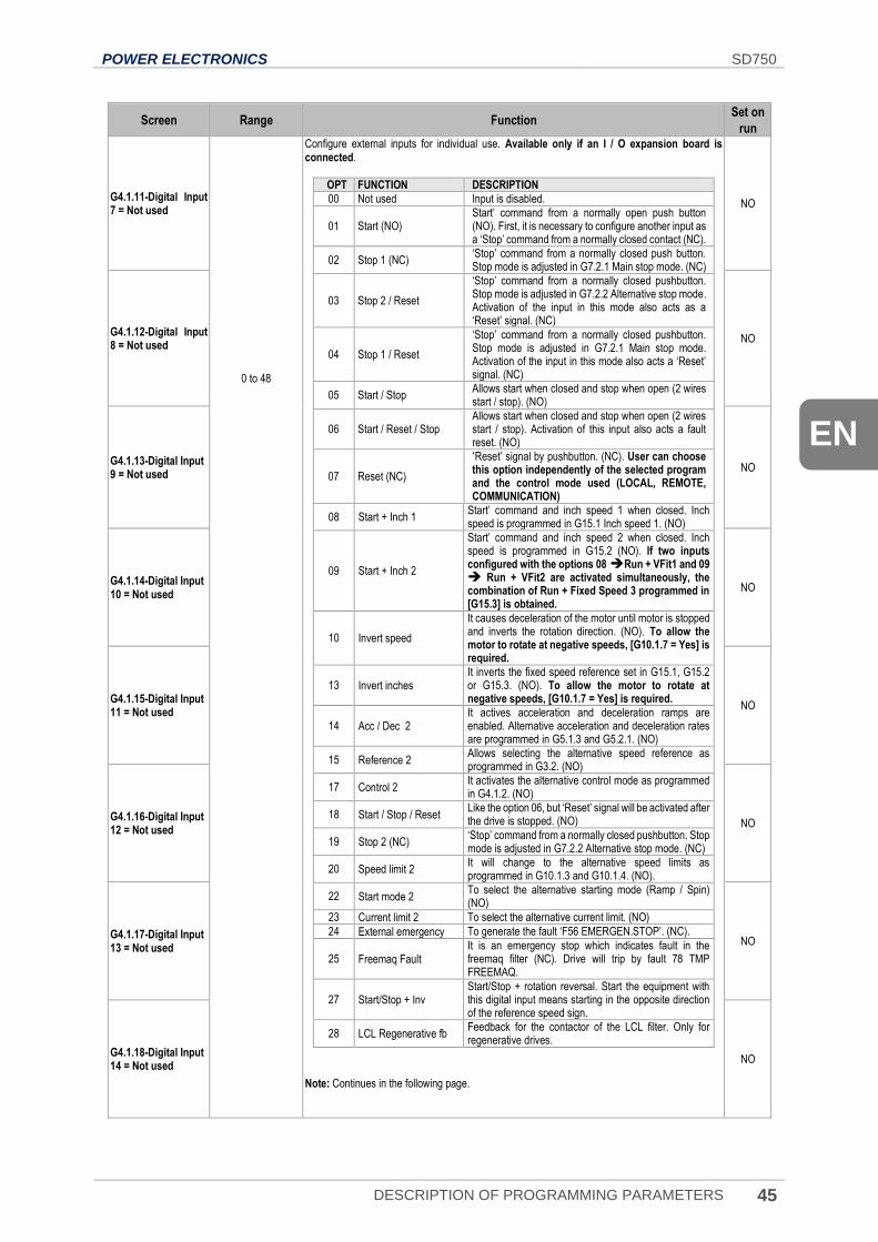
POWER ELECTRONICS SD750
DESCRIPTION OF PROGRAMMING PARAMETERS 45
EN
Screen Range Function Set on
run
G4.1.11-Digital Input 7 = Not used
0 to 48
Configure external inputs for individual use. Available only if an I / O expansion board is connected.
OPT FUNCTION DESCRIPTION
00 Not used Input is disabled.
01 Start (NO) Start’ command from a normally open push button (NO). First, it is necessary to configure another input as a ‘Stop’ command from a normally closed contact (NC).
02 Stop 1 (NC) ‘Stop’ command from a normally closed push button. Stop mode is adjusted in G7.2.1 Main stop mode. (NC)
03 Stop 2 / Reset
‘Stop’ command from a normally closed pushbutton. Stop mode is adjusted in G7.2.2 Alternative stop mode. Activation of the input in this mode also acts as a ‘Reset’ signal. (NC)
04 Stop 1 / Reset
‘Stop’ command from a normally closed pushbutton. Stop mode is adjusted in G7.2.1 Main stop mode. Activation of the input in this mode also acts a ‘Reset’ signal. (NC)
05 Start / Stop Allows start when closed and stop when open (2 wires start / stop). (NO)
06 Start / Reset / Stop Allows start when closed and stop when open (2 wires start / stop). Activation of this input also acts a fault reset. (NO)
07 Reset (NC)
‘Reset’ signal by pushbutton. (NC). User can choose this option independently of the selected program and the control mode used (LOCAL, REMOTE, COMMUNICATION)
08 Start + Inch 1 Start’ command and inch speed 1 when closed. Inch speed is programmed in G15.1 Inch speed 1. (NO)
09 Start + Inch 2
Start’ command and inch speed 2 when closed. Inch speed is programmed in G15.2 (NO). If two inputs configured with the options 08 Run + VFit1 and 09 Run + VFit2 are activated simultaneously, the combination of Run + Fixed Speed 3 programmed in [G15.3] is obtained.
10 Invert speed
It causes deceleration of the motor until motor is stopped and inverts the rotation direction. (NO). To allow the motor to rotate at negative speeds, [G10.1.7 = Yes] is required.
13 Invert inches It inverts the fixed speed reference set in G15.1, G15.2 or G15.3. (NO). To allow the motor to rotate at negative speeds, [G10.1.7 = Yes] is required.
14 Acc / Dec 2 It actives acceleration and deceleration ramps are enabled. Alternative acceleration and deceleration rates are programmed in G5.1.3 and G5.2.1. (NO)
15 Reference 2 Allows selecting the alternative speed reference as programmed in G3.2. (NO)
17 Control 2 It activates the alternative control mode as programmed in G4.1.2. (NO)
18 Start / Stop / Reset Like the option 06, but ‘Reset’ signal will be activated after the drive is stopped. (NO)
19 Stop 2 (NC) ‘Stop’ command from a normally closed pushbutton. Stop mode is adjusted in G7.2.2 Alternative stop mode. (NC)
20 Speed limit 2 It will change to the alternative speed limits as programmed in G10.1.3 and G10.1.4. (NO).
22 Start mode 2 To select the alternative starting mode (Ramp / Spin) (NO)
23 Current limit 2 To select the alternative current limit. (NO)
24 External emergency To generate the fault ‘F56 EMERGEN.STOP’. (NC).
25 Freemaq Fault It is an emergency stop which indicates fault in the freemaq filter (NC). Drive will trip by fault 78 TMP FREEMAQ.
27 Start/Stop + Inv Start/Stop + rotation reversal. Start the equipment with this digital input means starting in the opposite direction of the reference speed sign.
28 LCL Regenerative fb Feedback for the contactor of the LCL filter. Only for regenerative drives.
Note: Continues in the following page.
NO
G4.1.12-Digital Input 8 = Not used
NO
G4.1.13-Digital Input 9 = Not used
NO
G4.1.14-Digital Input 10 = Not used
NO
G4.1.15-Digital Input 11 = Not used
NO
G4.1.16-Digital Input 12 = Not used
NO
G4.1.17-Digital Input 13 = Not used
NO
G4.1.18-Digital Input 14 = Not used
NO
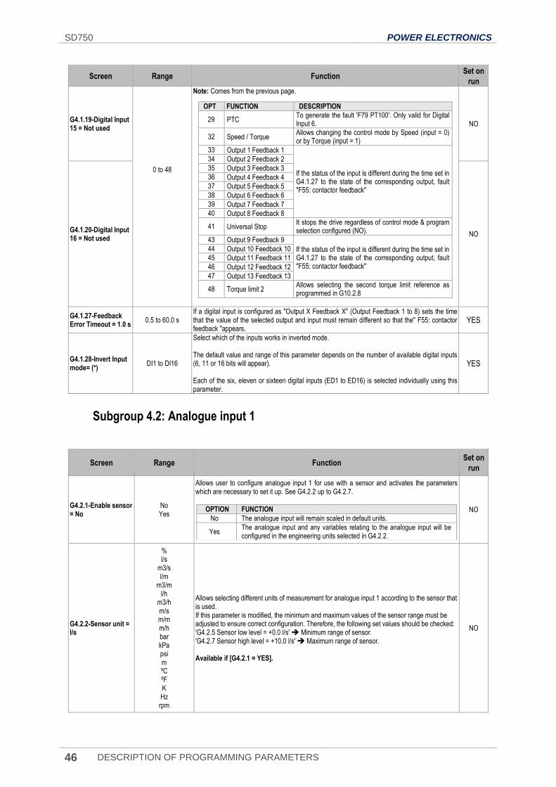
SD750 POWER ELECTRONICS
46 DESCRIPTION OF PROGRAMMING PARAMETERS
Screen Range Function Set on
run
G4.1.19-Digital Input 15 = Not used
0 to 48
Note: Comes from the previous page.
OPT FUNCTION DESCRIPTION
29 PTC To generate the fault 'F79 PT100'. Only valid for Digital Input 6.
32 Speed / Torque Allows changing the control mode by Speed (input = 0) or by Torque (input = 1)
33 Output 1 Feedback 1
If the status of the input is different during the time set in G4.1.27 to the state of the corresponding output, fault "F55: contactor feedback"
34 Output 2 Feedback 2
35 Output 3 Feedback 3
36 Output 4 Feedback 4
37 Output 5 Feedback 5
38 Output 6 Feedback 6
39 Output 7 Feedback 7
40 Output 8 Feedback 8
41 Universal Stop It stops the drive regardless of control mode & program selection configured (NO).
43 Output 9 Feedback 9
If the status of the input is different during the time set in G4.1.27 to the state of the corresponding output, fault "F55: contactor feedback"
44 Output 10 Feedback 10
45 Output 11 Feedback 11
46 Output 12 Feedback 12
47 Output 13 Feedback 13
48 Torque limit 2 Allows selecting the second torque limit reference as programmed in G10.2.8
NO
G4.1.20-Digital Input 16 = Not used
NO
G4.1.27-Feedback Error Timeout = 1.0 s
0.5 to 60.0 s If a digital input is configured as "Output X Feedback X" (Output Feedback 1 to 8) sets the time that the value of the selected output and input must remain different so that the" F55: contactor feedback "appears.
YES
G4.1.28-Invert Input mode= (*)
DI1 to DI16
Select which of the inputs works in inverted mode. The default value and range of this parameter depends on the number of available digital inputs (6, 11 or 16 bits will appear). Each of the six, eleven or sixteen digital inputs (ED1 to ED16) is selected individually using this parameter.
YES
Subgroup 4.2: Analogue input 1
Screen Range Function Set on
run
G4.2.1-Enable sensor = No
No Yes
Allows user to configure analogue input 1 for use with a sensor and activates the parameters which are necessary to set it up. See G4.2.2 up to G4.2.7.
OPTION FUNCTION
No The analogue input will remain scaled in default units.
Yes The analogue input and any variables relating to the analogue input will be configured in the engineering units selected in G4.2.2.
NO
G4.2.2-Sensor unit = l/s
% l/s
m3/s l/m
m3/m l/h
m3/h m/s m/m m/h bar kPa psi m ºC ºF K Hz rpm
Allows selecting different units of measurement for analogue input 1 according to the sensor that is used. If this parameter is modified, the minimum and maximum values of the sensor range must be adjusted to ensure correct configuration. Therefore, the following set values should be checked: 'G4.2.5 Sensor low level = +0.0 l/s' Minimum range of sensor. 'G4.2.7 Sensor high level = +10.0 l/s' Maximum range of sensor. Available if [G4.2.1 = YES].
NO
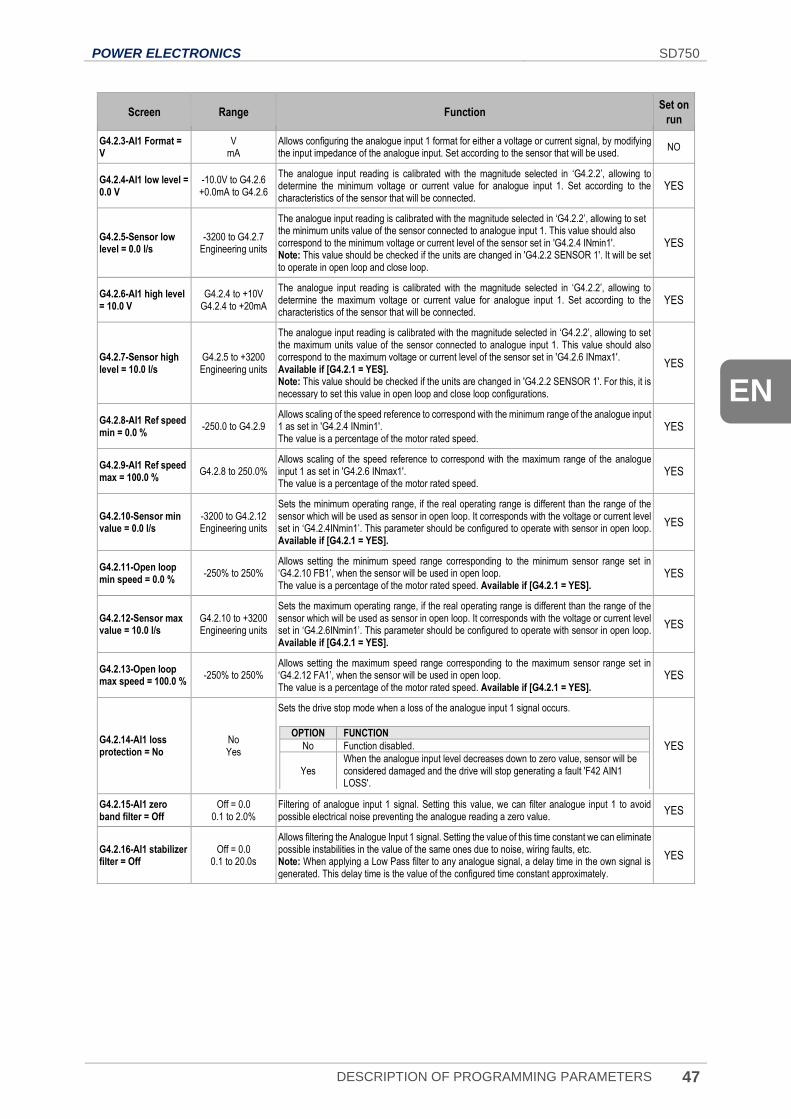
POWER ELECTRONICS SD750
DESCRIPTION OF PROGRAMMING PARAMETERS 47
EN
Screen Range Function Set on
run
G4.2.3-AI1 Format = V
V mA
Allows configuring the analogue input 1 format for either a voltage or current signal, by modifying the input impedance of the analogue input. Set according to the sensor that will be used.
NO
G4.2.4-AI1 low level = 0.0 V
-10.0V to G4.2.6 +0.0mA to G4.2.6
The analogue input reading is calibrated with the magnitude selected in ‘G4.2.2’, allowing to determine the minimum voltage or current value for analogue input 1. Set according to the characteristics of the sensor that will be connected.
YES
G4.2.5-Sensor low level = 0.0 l/s
-3200 to G4.2.7 Engineering units
The analogue input reading is calibrated with the magnitude selected in ‘G4.2.2’, allowing to set the minimum units value of the sensor connected to analogue input 1. This value should also correspond to the minimum voltage or current level of the sensor set in 'G4.2.4 INmin1'. Note: This value should be checked if the units are changed in 'G4.2.2 SENSOR 1'. It will be set to operate in open loop and close loop.
YES
G4.2.6-AI1 high level = 10.0 V
G4.2.4 to +10V G4.2.4 to +20mA
The analogue input reading is calibrated with the magnitude selected in ‘G4.2.2’, allowing to determine the maximum voltage or current value for analogue input 1. Set according to the characteristics of the sensor that will be connected.
YES
G4.2.7-Sensor high level = 10.0 l/s
G4.2.5 to +3200 Engineering units
The analogue input reading is calibrated with the magnitude selected in ‘G4.2.2’, allowing to set the maximum units value of the sensor connected to analogue input 1. This value should also correspond to the maximum voltage or current level of the sensor set in 'G4.2.6 INmax1'. Available if [G4.2.1 = YES]. Note: This value should be checked if the units are changed in 'G4.2.2 SENSOR 1'. For this, it is necessary to set this value in open loop and close loop configurations.
YES
G4.2.8-AI1 Ref speed min = 0.0 %
-250.0 to G4.2.9 Allows scaling of the speed reference to correspond with the minimum range of the analogue input 1 as set in 'G4.2.4 INmin1'. The value is a percentage of the motor rated speed.
YES
G4.2.9-AI1 Ref speed max = 100.0 %
G4.2.8 to 250.0% Allows scaling of the speed reference to correspond with the maximum range of the analogue input 1 as set in 'G4.2.6 INmax1'. The value is a percentage of the motor rated speed.
YES
G4.2.10-Sensor min value = 0.0 l/s
-3200 to G4.2.12 Engineering units
Sets the minimum operating range, if the real operating range is different than the range of the sensor which will be used as sensor in open loop. It corresponds with the voltage or current level set in ‘G4.2.4INmin1’. This parameter should be configured to operate with sensor in open loop. Available if [G4.2.1 = YES].
YES
G4.2.11-Open loop min speed = 0.0 %
-250% to 250% Allows setting the minimum speed range corresponding to the minimum sensor range set in ‘G4.2.10 FB1’, when the sensor will be used in open loop. The value is a percentage of the motor rated speed. Available if [G4.2.1 = YES].
YES
G4.2.12-Sensor max value = 10.0 l/s
G4.2.10 to +3200 Engineering units
Sets the maximum operating range, if the real operating range is different than the range of the sensor which will be used as sensor in open loop. It corresponds with the voltage or current level set in ‘G4.2.6INmin1’. This parameter should be configured to operate with sensor in open loop. Available if [G4.2.1 = YES].
YES
G4.2.13-Open loop max speed = 100.0 %
-250% to 250% Allows setting the maximum speed range corresponding to the maximum sensor range set in ‘G4.2.12 FA1’, when the sensor will be used in open loop. The value is a percentage of the motor rated speed. Available if [G4.2.1 = YES].
YES
G4.2.14-AI1 loss protection = No
No Yes
Sets the drive stop mode when a loss of the analogue input 1 signal occurs.
OPTION FUNCTION
No Function disabled.
Yes When the analogue input level decreases down to zero value, sensor will be considered damaged and the drive will stop generating a fault 'F42 AIN1 LOSS'.
YES
G4.2.15-AI1 zero band filter = Off
Off = 0.0 0.1 to 2.0%
Filtering of analogue input 1 signal. Setting this value, we can filter analogue input 1 to avoid possible electrical noise preventing the analogue reading a zero value.
YES
G4.2.16-AI1 stabilizer filter = Off
Off = 0.0 0.1 to 20.0s
Allows filtering the Analogue Input 1 signal. Setting the value of this time constant we can eliminate possible instabilities in the value of the same ones due to noise, wiring faults, etc. Note: When applying a Low Pass filter to any analogue signal, a delay time in the own signal is generated. This delay time is the value of the configured time constant approximately.
YES
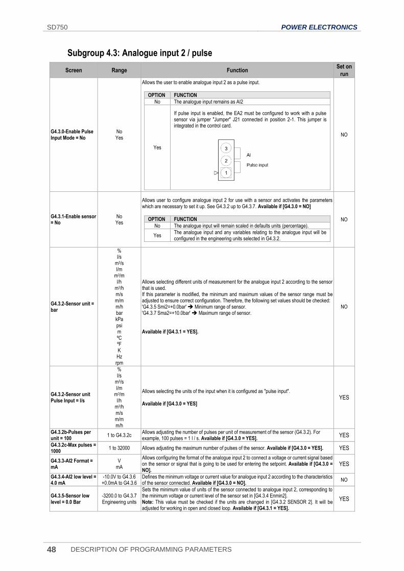
SD750 POWER ELECTRONICS
48 DESCRIPTION OF PROGRAMMING PARAMETERS
Subgroup 4.3: Analogue input 2 / pulse
Screen Range Function Set on
run
G4.3.0-Enable Pulse Input Mode = No
No Yes
Allows the user to enable analogue input 2 as a pulse input.
OPTION FUNCTION
No The analogue input remains as AI2
Yes
If pulse input is enabled, the EA2 must be configured to work with a pulse sensor via jumper "Jumper" J21 connected in position 2-1. This jumper is integrated in the control card.
NO
G4.3.1-Enable sensor = No
No Yes
Allows user to configure analogue input 2 for use with a sensor and activates the parameters which are necessary to set it up. See G4.3.2 up to G4.3.7. Available if [G4.3.0 = NO]
OPTION FUNCTION
No The analogue input will remain scaled in defaults units (percentage).
Yes The analogue input and any variables relating to the analogue input will be configured in the engineering units selected in G4.3.2.
NO
G4.3.2-Sensor unit = bar
% l/s
m3/s l/m
m3/m l/h
m3/h m/s m/m m/h bar kPa psi m ºC ºF K Hz rpm
Allows selecting different units of measurement for the analogue input 2 according to the sensor that is used. If this parameter is modified, the minimum and maximum values of the sensor range must be adjusted to ensure correct configuration. Therefore, the following set values should be checked: 'G4.3.5 Smi2=+0.0bar' Minimum range of sensor. 'G4.3.7 Sma2=+10.0bar' Maximum range of sensor. Available if [G4.3.1 = YES].
NO
G4.3.2-Sensor unit Pulse Input = l/s
% l/s
m3/s l/m
m3/m l/h
m3/h m/s m/m m/h
Allows selecting the units of the input when it is configured as "pulse input". Available if [G4.3.0 = YES]
YES
G4.3.2b-Pulses per unit = 100
1 to G4.3.2c Allows adjusting the number of pulses per unit of measurement of the sensor (G4.3.2). For example, 100 pulses = 1 l / s. Available if [G4.3.0 = YES].
YES
G4.3.2c-Max pulses = 1000
1 to 32000 Allows adjusting the maximum number of pulses of the sensor. Available if [G4.3.0 = YES]. YES
G4.3.3-AI2 Format = mA
V mA
Allows configuring the format of the analogue input 2 to connect a voltage or current signal based on the sensor or signal that is going to be used for entering the setpoint. Available if [G4.3.0 = NO].
YES
G4.3.4-AI2 low level = 4.0 mA
-10.0V to G4.3.6 +0.0mA to G4.3.6
Defines the minimum voltage or current value for analogue input 2 according to the characteristics of the sensor connected. Available if [G4.3.0 = NO].
NO
G4.3.5-Sensor low level = 0.0 Bar
-3200.0 to G4.3.7 Engineering units
Sets the minimum value of units of the sensor connected to analogue input 2, corresponding to the minimum voltage or current level of the sensor set in [G4.3.4 Enmin2]. Note: This value must be checked if the units are changed in [G4.3.2 SENSOR 2]. It will be adjusted for working in open and closed loop. Available if [G4.3.1 = YES].
YES
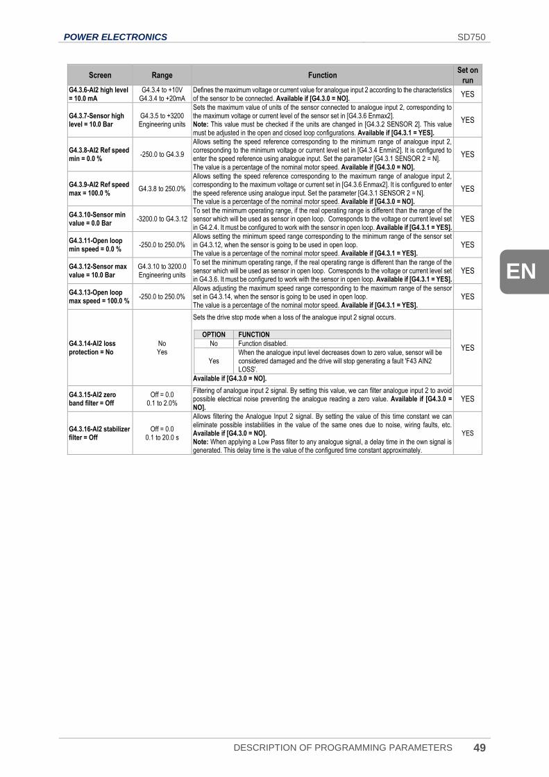
POWER ELECTRONICS SD750
DESCRIPTION OF PROGRAMMING PARAMETERS 49
EN
Screen Range Function Set on
run
G4.3.6-AI2 high level = 10.0 mA
G4.3.4 to +10V G4.3.4 to +20mA
Defines the maximum voltage or current value for analogue input 2 according to the characteristics of the sensor to be connected. Available if [G4.3.0 = NO].
YES
G4.3.7-Sensor high level = 10.0 Bar
G4.3.5 to +3200 Engineering units
Sets the maximum value of units of the sensor connected to analogue input 2, corresponding to the maximum voltage or current level of the sensor set in [G4.3.6 Enmax2]. Note: This value must be checked if the units are changed in [G4.3.2 SENSOR 2]. This value must be adjusted in the open and closed loop configurations. Available if [G4.3.1 = YES].
YES
G4.3.8-AI2 Ref speed min = 0.0 %
-250.0 to G4.3.9
Allows setting the speed reference corresponding to the minimum range of analogue input 2, corresponding to the minimum voltage or current level set in [G4.3.4 Enmin2]. It is configured to enter the speed reference using analogue input. Set the parameter [G4.3.1 SENSOR 2 = N]. The value is a percentage of the nominal motor speed. Available if [G4.3.0 = NO].
YES
G4.3.9-AI2 Ref speed max = 100.0 %
G4.3.8 to 250.0%
Allows setting the speed reference corresponding to the maximum range of analogue input 2, corresponding to the maximum voltage or current set in [G4.3.6 Enmax2]. It is configured to enter the speed reference using analogue input. Set the parameter [G4.3.1 SENSOR 2 = N]. The value is a percentage of the nominal motor speed. Available if [G4.3.0 = NO].
YES
G4.3.10-Sensor min value = 0.0 Bar
-3200.0 to G4.3.12 To set the minimum operating range, if the real operating range is different than the range of the sensor which will be used as sensor in open loop. Corresponds to the voltage or current level set in G4.2.4. It must be configured to work with the sensor in open loop. Available if [G4.3.1 = YES].
YES
G4.3.11-Open loop min speed = 0.0 %
-250.0 to 250.0% Allows setting the minimum speed range corresponding to the minimum range of the sensor set in G4.3.12, when the sensor is going to be used in open loop. The value is a percentage of the nominal motor speed. Available if [G4.3.1 = YES].
YES
G4.3.12-Sensor max value = 10.0 Bar
G4.3.10 to 3200.0 Engineering units
To set the minimum operating range, if the real operating range is different than the range of the sensor which will be used as sensor in open loop. Corresponds to the voltage or current level set in G4.3.6. It must be configured to work with the sensor in open loop. Available if [G4.3.1 = YES].
YES
G4.3.13-Open loop max speed = 100.0 %
-250.0 to 250.0% Allows adjusting the maximum speed range corresponding to the maximum range of the sensor set in G4.3.14, when the sensor is going to be used in open loop. The value is a percentage of the nominal motor speed. Available if [G4.3.1 = YES].
YES
G4.3.14-AI2 loss protection = No
No Yes
Sets the drive stop mode when a loss of the analogue input 2 signal occurs.
OPTION FUNCTION
No Function disabled.
Yes When the analogue input level decreases down to zero value, sensor will be considered damaged and the drive will stop generating a fault 'F43 AIN2 LOSS'.
Available if [G4.3.0 = NO].
YES
G4.3.15-AI2 zero band filter = Off
Off = 0.0 0.1 to 2.0%
Filtering of analogue input 2 signal. By setting this value, we can filter analogue input 2 to avoid possible electrical noise preventing the analogue reading a zero value. Available if [G4.3.0 = NO].
YES
G4.3.16-AI2 stabilizer filter = Off
Off = 0.0 0.1 to 20.0 s
Allows filtering the Analogue Input 2 signal. By setting the value of this time constant we can eliminate possible instabilities in the value of the same ones due to noise, wiring faults, etc. Available if [G4.3.0 = NO]. Note: When applying a Low Pass filter to any analogue signal, a delay time in the own signal is generated. This delay time is the value of the configured time constant approximately.
YES
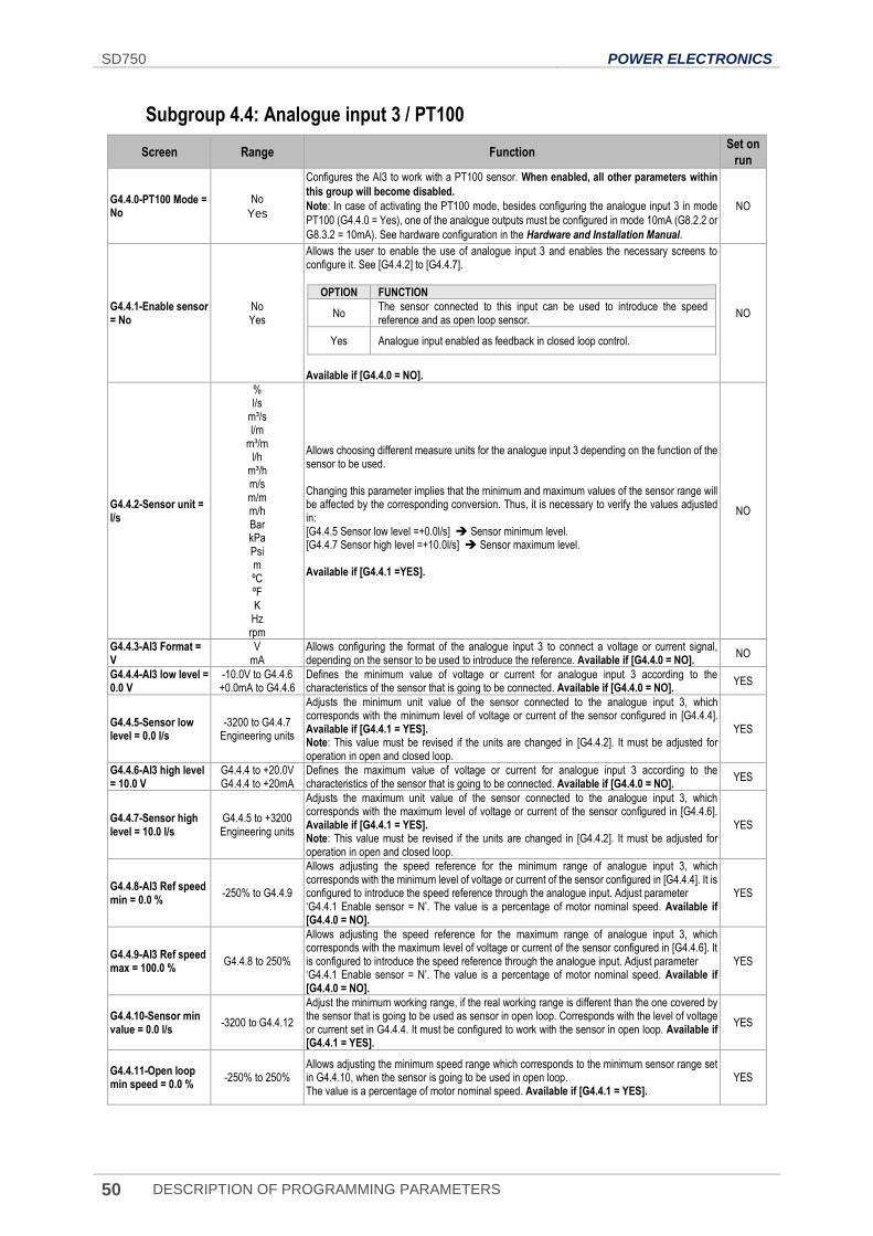
SD750 POWER ELECTRONICS
50 DESCRIPTION OF PROGRAMMING PARAMETERS
Subgroup 4.4: Analogue input 3 / PT100
Screen Range Function Set on
run
G4.4.0-PT100 Mode = No
No
Yes
Configures the AI3 to work with a PT100 sensor. When enabled, all other parameters within
this group will become disabled.
Note: In case of activating the PT100 mode, besides configuring the analogue input 3 in mode
PT100 (G4.4.0 = Yes), one of the analogue outputs must be configured in mode 10mA (G8.2.2 or
G8.3.2 = 10mA). See hardware configuration in the Hardware and Installation Manual.
NO
G4.4.1-Enable sensor = No
No Yes
Allows the user to enable the use of analogue input 3 and enables the necessary screens to configure it. See [G4.4.2] to [G4.4.7].
OPTION FUNCTION
No The sensor connected to this input can be used to introduce the speed reference and as open loop sensor.
Yes Analogue input enabled as feedback in closed loop control.
Available if [G4.4.0 = NO].
NO
G4.4.2-Sensor unit = l/s
% l/s
m³/s l/m
m³/m l/h
m³/h m/s m/m m/h Bar kPa Psi m ºC ºF K Hz rpm
Allows choosing different measure units for the analogue input 3 depending on the function of the sensor to be used. Changing this parameter implies that the minimum and maximum values of the sensor range will be affected by the corresponding conversion. Thus, it is necessary to verify the values adjusted in: [G4.4.5 Sensor low level =+0.0l/s] Sensor minimum level. [G4.4.7 Sensor high level =+10.0l/s] Sensor maximum level. Available if [G4.4.1 =YES].
NO
G4.4.3-AI3 Format = V
V mA
Allows configuring the format of the analogue input 3 to connect a voltage or current signal, depending on the sensor to be used to introduce the reference. Available if [G4.4.0 = NO].
NO
G4.4.4-AI3 low level = 0.0 V
-10.0V to G4.4.6 +0.0mA to G4.4.6
Defines the minimum value of voltage or current for analogue input 3 according to the characteristics of the sensor that is going to be connected. Available if [G4.4.0 = NO].
YES
G4.4.5-Sensor low level = 0.0 l/s
-3200 to G4.4.7 Engineering units
Adjusts the minimum unit value of the sensor connected to the analogue input 3, which corresponds with the minimum level of voltage or current of the sensor configured in [G4.4.4]. Available if [G4.4.1 = YES]. Note: This value must be revised if the units are changed in [G4.4.2]. It must be adjusted for operation in open and closed loop.
YES
G4.4.6-AI3 high level = 10.0 V
G4.4.4 to +20.0V G4.4.4 to +20mA
Defines the maximum value of voltage or current for analogue input 3 according to the characteristics of the sensor that is going to be connected. Available if [G4.4.0 = NO].
YES
G4.4.7-Sensor high level = 10.0 l/s
G4.4.5 to +3200 Engineering units
Adjusts the maximum unit value of the sensor connected to the analogue input 3, which corresponds with the maximum level of voltage or current of the sensor configured in [G4.4.6]. Available if [G4.4.1 = YES]. Note: This value must be revised if the units are changed in [G4.4.2]. It must be adjusted for operation in open and closed loop.
YES
G4.4.8-AI3 Ref speed min = 0.0 %
-250% to G4.4.9
Allows adjusting the speed reference for the minimum range of analogue input 3, which corresponds with the minimum level of voltage or current of the sensor configured in [G4.4.4]. It is configured to introduce the speed reference through the analogue input. Adjust parameter ‘G4.4.1 Enable sensor = N’. The value is a percentage of motor nominal speed. Available if [G4.4.0 = NO].
YES
G4.4.9-AI3 Ref speed max = 100.0 %
G4.4.8 to 250%
Allows adjusting the speed reference for the maximum range of analogue input 3, which corresponds with the maximum level of voltage or current of the sensor configured in [G4.4.6]. It is configured to introduce the speed reference through the analogue input. Adjust parameter ‘G4.4.1 Enable sensor = N’. The value is a percentage of motor nominal speed. Available if [G4.4.0 = NO].
YES
G4.4.10-Sensor min value = 0.0 l/s
-3200 to G4.4.12
Adjust the minimum working range, if the real working range is different than the one covered by the sensor that is going to be used as sensor in open loop. Corresponds with the level of voltage or current set in G4.4.4. It must be configured to work with the sensor in open loop. Available if [G4.4.1 = YES].
YES
G4.4.11-Open loop min speed = 0.0 %
-250% to 250% Allows adjusting the minimum speed range which corresponds to the minimum sensor range set in G4.4.10, when the sensor is going to be used in open loop. The value is a percentage of motor nominal speed. Available if [G4.4.1 = YES].
YES
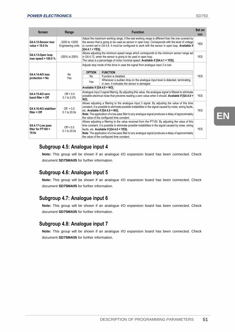
POWER ELECTRONICS SD750
DESCRIPTION OF PROGRAMMING PARAMETERS 51
EN
Screen Range Function Set on
run
G4.4.12-Sensor max value = 10.0 l/s
-3200 to +3200 Engineering units
Adjust the maximum working range, if the real working range is different than the one covered by the sensor that is going to be used as sensor in open loop. Corresponds with the level of voltage or current set in G4.4.6. It must be configured to work with the sensor in open loop. Available if [G4.4.1 = YES].
YES
G4.4.13-Open loop max speed = 100.0 %
-250% to 250% Allows adjusting the minimum speed range which corresponds to the minimum sensor range set in G4.4.12, when the sensor is going to be used in open loop. The value is a percentage of motor nominal speed. Available if [G4.4.1 = YES].
YES
G4.4.14-AI3 loss protection = No
No Yes
Adjusts stop mode of the drive in case the signal from analogue input 3 is lost.
OPTION FUNCTION
No Function is disabled.
Yes Whenever a sudden drop on the analogue input level is detected, terminating in zero, it indicates the sensor is damaged.
Available if [G4.4.0 = NO].
YES
G4.4.15-AI3 zero band filter = Off
Off = 0.0 0.1 to 2.0%
Analogue input 3 signal filtering. By adjusting this value, the analogue signal is filtered to eliminate possible electrical noise that prevents reading a zero value when it should. Available if [G4.4.0 = NO].
YES
G4.4.16-AI3 stabilizer filter = Off
Off = 0.0 0.1 to 20.0s
Allows adjusting a filtering to the analogue input 3 signal. By adjusting the value of this time constant, it is possible to eliminate possible instabilities in the signal caused by noise, wiring faults, etc. Available if [G4.4.0 = NO]. Note: The application of a low pass filter to any analogue signal produces a delay of approximately the value of the configured time constant.
YES
G4.4.17-Low pass filter for PT100 = 10.0s
Off = 0.0 0.1 to 20.0s
Allows adjusting a filtering to the value received from the PT100. By adjusting the value of this
time constant, it is possible to eliminate possible instabilities in the signal caused by noise, wiring
faults, etc. Available if [G4.4.0 = YES].
Note: The application of a low pass filter to any analogue signal produces a delay of approximately the value of the configured time constant.
YES
Subgroup 4.5: Analogue input 4
Note: This group will be shown if an analogue I/O expansion board has been connected. Check
document SD75MA05 for further information.
Subgroup 4.6: Analogue input 5
Note: This group will be shown if an analogue I/O expansion board has been connected. Check
document SD75MA05 for further information.
Subgroup 4.7: Analogue input 6
Note: This group will be shown if an analogue I/O expansion board has been connected. Check
document SD75MA05 for further information.
Subgroup 4.8: Analogue input 7
Note: This group will be shown if an analogue I/O expansion board has been connected. Check
document SD75MA05 for further information.
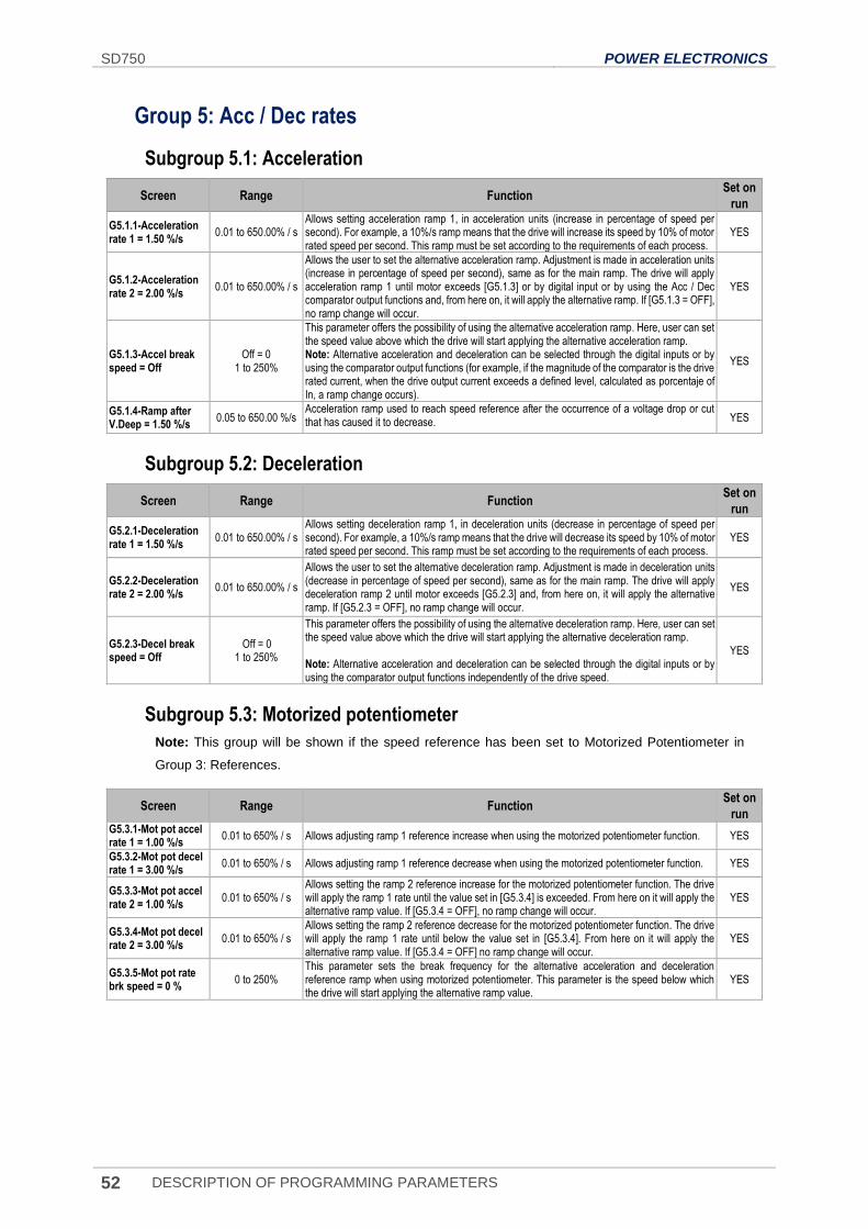
SD750 POWER ELECTRONICS
52 DESCRIPTION OF PROGRAMMING PARAMETERS
Group 5: Acc / Dec rates
Subgroup 5.1: Acceleration
Screen Range Function Set on
run
G5.1.1-Acceleration rate 1 = 1.50 %/s
0.01 to 650.00% / s Allows setting acceleration ramp 1, in acceleration units (increase in percentage of speed per second). For example, a 10%/s ramp means that the drive will increase its speed by 10% of motor rated speed per second. This ramp must be set according to the requirements of each process.
YES
G5.1.2-Acceleration rate 2 = 2.00 %/s
0.01 to 650.00% / s
Allows the user to set the alternative acceleration ramp. Adjustment is made in acceleration units (increase in percentage of speed per second), same as for the main ramp. The drive will apply acceleration ramp 1 until motor exceeds [G5.1.3] or by digital input or by using the Acc / Dec comparator output functions and, from here on, it will apply the alternative ramp. If [G5.1.3 = OFF], no ramp change will occur.
YES
G5.1.3-Accel break speed = Off
Off = 0 1 to 250%
This parameter offers the possibility of using the alternative acceleration ramp. Here, user can set the speed value above which the drive will start applying the alternative acceleration ramp. Note: Alternative acceleration and deceleration can be selected through the digital inputs or by using the comparator output functions (for example, if the magnitude of the comparator is the drive rated current, when the drive output current exceeds a defined level, calculated as porcentaje of In, a ramp change occurs).
YES
G5.1.4-Ramp after V.Deep = 1.50 %/s
0.05 to 650.00 %/s Acceleration ramp used to reach speed reference after the occurrence of a voltage drop or cut that has caused it to decrease. YES
Subgroup 5.2: Deceleration
Screen Range Function Set on
run
G5.2.1-Deceleration rate 1 = 1.50 %/s
0.01 to 650.00% / s Allows setting deceleration ramp 1, in deceleration units (decrease in percentage of speed per second). For example, a 10%/s ramp means that the drive will decrease its speed by 10% of motor rated speed per second. This ramp must be set according to the requirements of each process.
YES
G5.2.2-Deceleration rate 2 = 2.00 %/s
0.01 to 650.00% / s
Allows the user to set the alternative deceleration ramp. Adjustment is made in deceleration units (decrease in percentage of speed per second), same as for the main ramp. The drive will apply deceleration ramp 2 until motor exceeds [G5.2.3] and, from here on, it will apply the alternative ramp. If [G5.2.3 = OFF], no ramp change will occur.
YES
G5.2.3-Decel break speed = Off
Off = 0 1 to 250%
This parameter offers the possibility of using the alternative deceleration ramp. Here, user can set the speed value above which the drive will start applying the alternative deceleration ramp. Note: Alternative acceleration and deceleration can be selected through the digital inputs or by using the comparator output functions independently of the drive speed.
YES
Subgroup 5.3: Motorized potentiometer
Note: This group will be shown if the speed reference has been set to Motorized Potentiometer in
Group 3: References.
Screen Range Function Set on
run G5.3.1-Mot pot accel rate 1 = 1.00 %/s
0.01 to 650% / s Allows adjusting ramp 1 reference increase when using the motorized potentiometer function. YES
G5.3.2-Mot pot decel rate 1 = 3.00 %/s
0.01 to 650% / s Allows adjusting ramp 1 reference decrease when using the motorized potentiometer function. YES
G5.3.3-Mot pot accel rate 2 = 1.00 %/s
0.01 to 650% / s Allows setting the ramp 2 reference increase for the motorized potentiometer function. The drive will apply the ramp 1 rate until the value set in [G5.3.4] is exceeded. From here on it will apply the alternative ramp value. If [G5.3.4 = OFF], no ramp change will occur.
YES
G5.3.4-Mot pot decel rate 2 = 3.00 %/s
0.01 to 650% / s Allows setting the ramp 2 reference decrease for the motorized potentiometer function. The drive will apply the ramp 1 rate until below the value set in [G5.3.4]. From here on it will apply the alternative ramp value. If [G5.3.4 = OFF] no ramp change will occur.
YES
G5.3.5-Mot pot rate brk speed = 0 %
0 to 250% This parameter sets the break frequency for the alternative acceleration and deceleration reference ramp when using motorized potentiometer. This parameter is the speed below which the drive will start applying the alternative ramp value.
YES
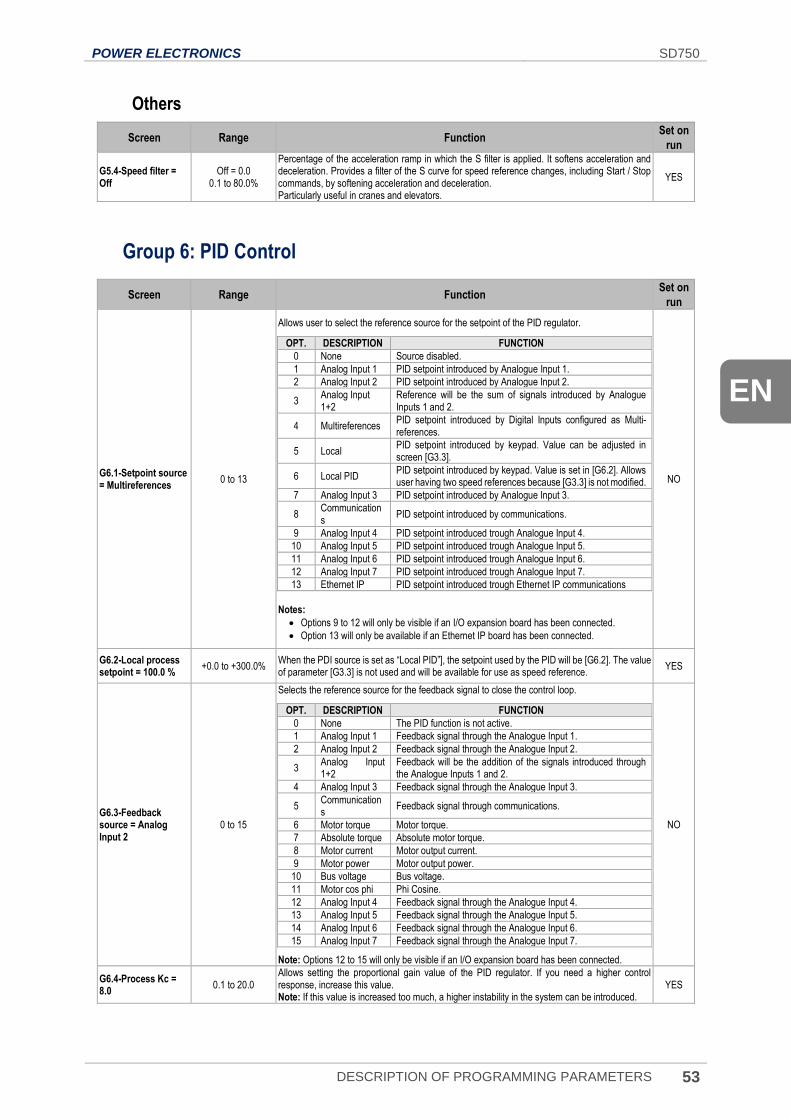
POWER ELECTRONICS SD750
DESCRIPTION OF PROGRAMMING PARAMETERS 53
EN
Others
Screen Range Function Set on
run
G5.4-Speed filter = Off
Off = 0.0 0.1 to 80.0%
Percentage of the acceleration ramp in which the S filter is applied. It softens acceleration and deceleration. Provides a filter of the S curve for speed reference changes, including Start / Stop commands, by softening acceleration and deceleration. Particularly useful in cranes and elevators.
YES
Group 6: PID Control
Screen Range Function Set on
run
G6.1-Setpoint source = Multireferences
0 to 13
Allows user to select the reference source for the setpoint of the PID regulator.
OPT. DESCRIPTION FUNCTION
0 None Source disabled.
1 Analog Input 1 PID setpoint introduced by Analogue Input 1.
2 Analog Input 2 PID setpoint introduced by Analogue Input 2.
3 Analog Input 1+2
Reference will be the sum of signals introduced by Analogue Inputs 1 and 2.
4 Multireferences PID setpoint introduced by Digital Inputs configured as Multi-references.
5 Local PID setpoint introduced by keypad. Value can be adjusted in screen [G3.3].
6 Local PID PID setpoint introduced by keypad. Value is set in [G6.2]. Allows user having two speed references because [G3.3] is not modified.
7 Analog Input 3 PID setpoint introduced by Analogue Input 3.
8 Communications
PID setpoint introduced by communications.
9 Analog Input 4 PID setpoint introduced trough Analogue Input 4.
10 Analog Input 5 PID setpoint introduced trough Analogue Input 5.
11 Analog Input 6 PID setpoint introduced trough Analogue Input 6.
12 Analog Input 7 PID setpoint introduced trough Analogue Input 7.
13 Ethernet IP PID setpoint introduced trough Ethernet IP communications
Notes:
• Options 9 to 12 will only be visible if an I/O expansion board has been connected.
• Option 13 will only be available if an Ethernet IP board has been connected.
NO
G6.2-Local process setpoint = 100.0 %
+0.0 to +300.0% When the PDI source is set as “Local PID”], the setpoint used by the PID will be [G6.2]. The value of parameter [G3.3] is not used and will be available for use as speed reference.
YES
G6.3-Feedback source = Analog Input 2
0 to 15
Selects the reference source for the feedback signal to close the control loop.
OPT. DESCRIPTION FUNCTION
0 None The PID function is not active.
1 Analog Input 1 Feedback signal through the Analogue Input 1.
2 Analog Input 2 Feedback signal through the Analogue Input 2.
3 Analog Input 1+2
Feedback will be the addition of the signals introduced through the Analogue Inputs 1 and 2.
4 Analog Input 3 Feedback signal through the Analogue Input 3.
5 Communications
Feedback signal through communications.
6 Motor torque Motor torque.
7 Absolute torque Absolute motor torque.
8 Motor current Motor output current.
9 Motor power Motor output power.
10 Bus voltage Bus voltage.
11 Motor cos phi Phi Cosine.
12 Analog Input 4 Feedback signal through the Analogue Input 4.
13 Analog Input 5 Feedback signal through the Analogue Input 5.
14 Analog Input 6 Feedback signal through the Analogue Input 6.
15 Analog Input 7 Feedback signal through the Analogue Input 7.
Note: Options 12 to 15 will only be visible if an I/O expansion board has been connected.
NO
G6.4-Process Kc = 8.0
0.1 to 20.0 Allows setting the proportional gain value of the PID regulator. If you need a higher control response, increase this value. Note: If this value is increased too much, a higher instability in the system can be introduced.
YES
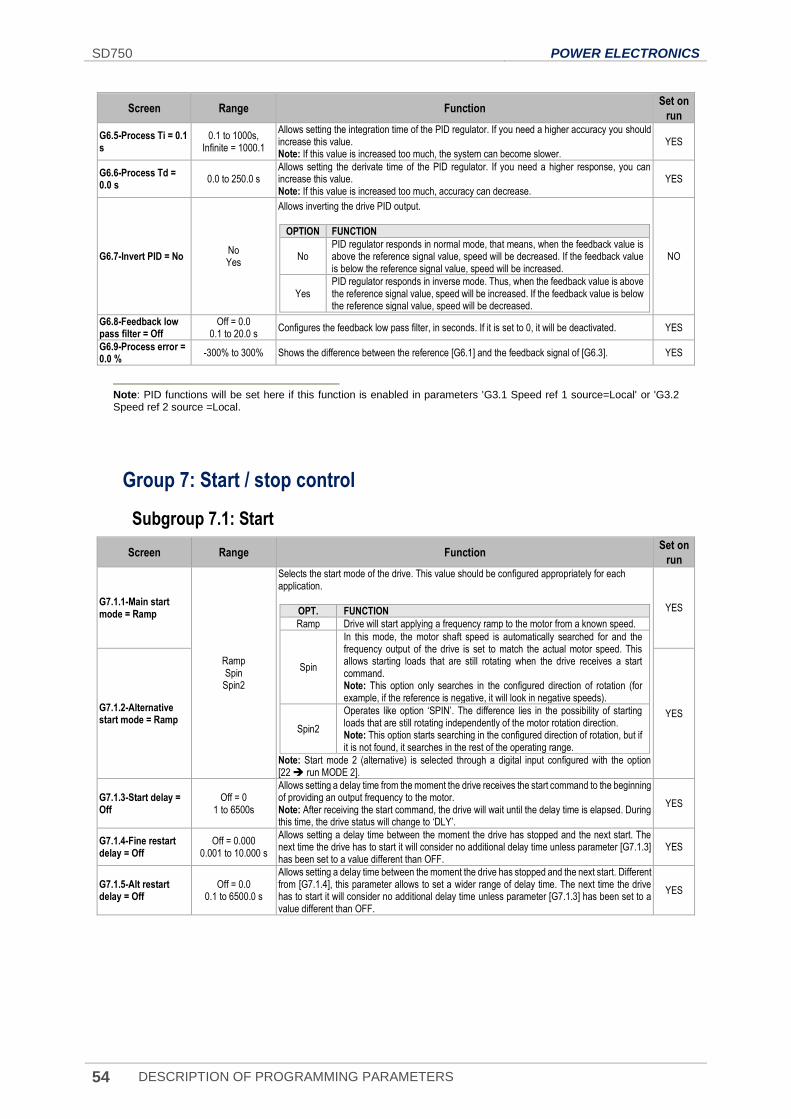
SD750 POWER ELECTRONICS
54 DESCRIPTION OF PROGRAMMING PARAMETERS
Screen Range Function Set on
run
G6.5-Process Ti = 0.1 s
0.1 to 1000s, Infinite = 1000.1
Allows setting the integration time of the PID regulator. If you need a higher accuracy you should increase this value. Note: If this value is increased too much, the system can become slower.
YES
G6.6-Process Td = 0.0 s
0.0 to 250.0 s Allows setting the derivate time of the PID regulator. If you need a higher response, you can increase this value. Note: If this value is increased too much, accuracy can decrease.
YES
G6.7-Invert PID = No No Yes
Allows inverting the drive PID output.
OPTION FUNCTION
No PID regulator responds in normal mode, that means, when the feedback value is above the reference signal value, speed will be decreased. If the feedback value is below the reference signal value, speed will be increased.
Yes PID regulator responds in inverse mode. Thus, when the feedback value is above the reference signal value, speed will be increased. If the feedback value is below the reference signal value, speed will be decreased.
NO
G6.8-Feedback low pass filter = Off
Off = 0.0 0.1 to 20.0 s
Configures the feedback low pass filter, in seconds. If it is set to 0, it will be deactivated. YES
G6.9-Process error = 0.0 %
-300% to 300% Shows the difference between the reference [G6.1] and the feedback signal of [G6.3]. YES
Note: PID functions will be set here if this function is enabled in parameters 'G3.1 Speed ref 1 source=Local' or 'G3.2 Speed ref 2 source =Local.
Group 7: Start / stop control
Subgroup 7.1: Start
Screen Range Function Set on
run
G7.1.1-Main start mode = Ramp
Ramp Spin
Spin2
Selects the start mode of the drive. This value should be configured appropriately for each application.
OPT. FUNCTION
Ramp Drive will start applying a frequency ramp to the motor from a known speed.
Spin
In this mode, the motor shaft speed is automatically searched for and the frequency output of the drive is set to match the actual motor speed. This allows starting loads that are still rotating when the drive receives a start command. Note: This option only searches in the configured direction of rotation (for example, if the reference is negative, it will look in negative speeds).
Spin2
Operates like option ‘SPIN’. The difference lies in the possibility of starting loads that are still rotating independently of the motor rotation direction. Note: This option starts searching in the configured direction of rotation, but if it is not found, it searches in the rest of the operating range.
Note: Start mode 2 (alternative) is selected through a digital input configured with the option [22 run MODE 2].
YES
G7.1.2-Alternative start mode = Ramp
YES
G7.1.3-Start delay = Off
Off = 0 1 to 6500s
Allows setting a delay time from the moment the drive receives the start command to the beginning of providing an output frequency to the motor. Note: After receiving the start command, the drive will wait until the delay time is elapsed. During this time, the drive status will change to ‘DLY’.
YES
G7.1.4-Fine restart delay = Off
Off = 0.000 0.001 to 10.000 s
Allows setting a delay time between the moment the drive has stopped and the next start. The next time the drive has to start it will consider no additional delay time unless parameter [G7.1.3] has been set to a value different than OFF.
YES
G7.1.5-Alt restart delay = Off
Off = 0.0 0.1 to 6500.0 s
Allows setting a delay time between the moment the drive has stopped and the next start. Different from [G7.1.4], this parameter allows to set a wider range of delay time. The next time the drive has to start it will consider no additional delay time unless parameter [G7.1.3] has been set to a value different than OFF.
YES
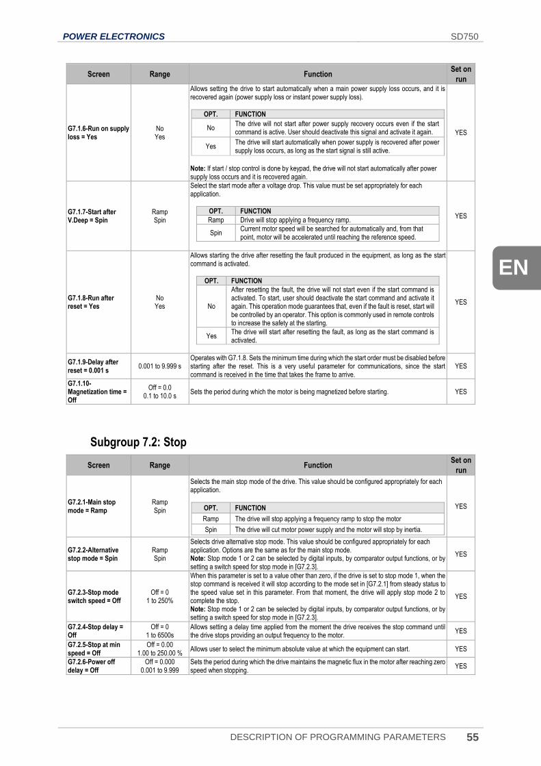
POWER ELECTRONICS SD750
DESCRIPTION OF PROGRAMMING PARAMETERS 55
EN
Screen Range Function Set on
run
G7.1.6-Run on supply loss = Yes
No Yes
Allows setting the drive to start automatically when a main power supply loss occurs, and it is recovered again (power supply loss or instant power supply loss).
OPT. FUNCTION
No The drive will not start after power supply recovery occurs even if the start command is active. User should deactivate this signal and activate it again.
Yes The drive will start automatically when power supply is recovered after power supply loss occurs, as long as the start signal is still active.
Note: If start / stop control is done by keypad, the drive will not start automatically after power supply loss occurs and it is recovered again.
YES
G7.1.7-Start after V.Deep = Spin
Ramp Spin
Select the start mode after a voltage drop. This value must be set appropriately for each application.
OPT. FUNCTION
Ramp Drive will stop applying a frequency ramp.
Spin Current motor speed will be searched for automatically and, from that point, motor will be accelerated until reaching the reference speed.
YES
G7.1.8-Run after reset = Yes
No Yes
Allows starting the drive after resetting the fault produced in the equipment, as long as the start command is activated.
OPT. FUNCTION
No
After resetting the fault, the drive will not start even if the start command is activated. To start, user should deactivate the start command and activate it again. This operation mode guarantees that, even if the fault is reset, start will be controlled by an operator. This option is commonly used in remote controls to increase the safety at the starting.
Yes The drive will start after resetting the fault, as long as the start command is activated.
YES
G7.1.9-Delay after reset = 0.001 s
0.001 to 9.999 s Operates with G7.1.8. Sets the minimum time during which the start order must be disabled before starting after the reset. This is a very useful parameter for communications, since the start command is received in the time that takes the frame to arrive.
YES
G7.1.10-Magnetization time = Off
Off = 0.0 0.1 to 10.0 s
Sets the period during which the motor is being magnetized before starting. YES
Subgroup 7.2: Stop
Screen Range Function Set on
run
G7.2.1-Main stop mode = Ramp
Ramp Spin
Selects the main stop mode of the drive. This value should be configured appropriately for each application.
OPT. FUNCTION
Ramp The drive will stop applying a frequency ramp to stop the motor
Spin The drive will cut motor power supply and the motor will stop by inertia.
YES
G7.2.2-Alternative stop mode = Spin
Ramp Spin
Selects drive alternative stop mode. This value should be configured appropriately for each application. Options are the same as for the main stop mode. Note: Stop mode 1 or 2 can be selected by digital inputs, by comparator output functions, or by setting a switch speed for stop mode in [G7.2.3].
YES
G7.2.3-Stop mode switch speed = Off
Off = 0 1 to 250%
When this parameter is set to a value other than zero, if the drive is set to stop mode 1, when the stop command is received it will stop according to the mode set in [G7.2.1] from steady status to the speed value set in this parameter. From that moment, the drive will apply stop mode 2 to complete the stop. Note: Stop mode 1 or 2 can be selected by digital inputs, by comparator output functions, or by setting a switch speed for stop mode in [G7.2.3].
YES
G7.2.4-Stop delay = Off
Off = 0 1 to 6500s
Allows setting a delay time applied from the moment the drive receives the stop command until the drive stops providing an output frequency to the motor.
YES
G7.2.5-Stop at min speed = Off
Off = 0.00 1.00 to 250.00 %
Allows user to select the minimum absolute value at which the equipment can start. YES
G7.2.6-Power off delay = Off
Off = 0.000 0.001 to 9.999
Sets the period during which the drive maintains the magnetic flux in the motor after reaching zero speed when stopping.
YES
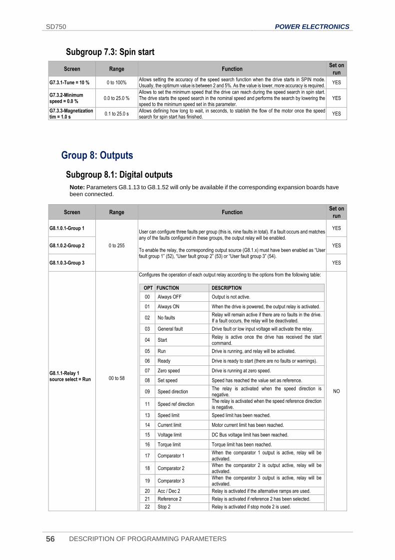
SD750 POWER ELECTRONICS
56 DESCRIPTION OF PROGRAMMING PARAMETERS
Subgroup 7.3: Spin start
Screen Range Function Set on
run
G7.3.1-Tune = 10 % 0 to 100% Allows setting the accuracy of the speed search function when the drive starts in SPIN mode. Usually, the optimum value is between 2 and 5%. As the value is lower, more accuracy is required.
YES
G7.3.2-Minimum speed = 0.0 %
0.0 to 25.0 % Allows to set the minimum speed that the drive can reach during the speed search in spin start. The drive starts the speed search in the nominal speed and performs the search by lowering the speed to the minimum speed set in this parameter.
YES
G7.3.3-Magnetization tim = 1.0 s
0.1 to 25.0 s Allows defining how long to wait, in seconds, to stablish the flow of the motor once the speed search for spin start has finished.
YES
Group 8: Outputs
Subgroup 8.1: Digital outputs
Note: Parameters G8.1.13 to G8.1.52 will only be available if the corresponding expansion boards have been connected.
Screen Range Function Set on
run
G8.1.0.1-Group 1
0 to 255
User can configure three faults per group (this is, nine faults in total). If a fault occurs and matches any of the faults configured in these groups, the output relay will be enabled. To enable the relay, the corresponding output source (G8.1.x) must have been enabled as “User fault group 1” (52), “User fault group 2” (53) or “User fault group 3” (54).
YES
G8.1.0.2-Group 2 YES
G8.1.0.3-Group 3 YES
G8.1.1-Relay 1 source select = Run
00 to 58
Configures the operation of each output relay according to the options from the following table:
OPT FUNCTION DESCRIPTION
00 Always OFF Output is not active.
01 Always ON When the drive is powered, the output relay is activated.
02 No faults Relay will remain active if there are no faults in the drive. If a fault occurs, the relay will be deactivated.
03 General fault Drive fault or low input voltage will activate the relay.
04 Start Relay is active once the drive has received the start command.
05 Run Drive is running, and relay will be activated.
06 Ready Drive is ready to start (there are no faults or warnings).
07 Zero speed Drive is running at zero speed.
08 Set speed Speed has reached the value set as reference.
09 Speed direction The relay is activated when the speed direction is negative.
11 Speed ref direction The relay is activated when the speed reference direction is negative.
13 Speed limit Speed limit has been reached.
14 Current limit Motor current limit has been reached.
15 Voltage limit DC Bus voltage limit has been reached.
16 Torque limit Torque limit has been reached.
17 Comparator 1 When the comparator 1 output is active, relay will be activated.
18 Comparator 2 When the comparator 2 is output active, relay will be activated.
19 Comparator 3 When the comparator 3 output is active, relay will be activated.
20 Acc / Dec 2 Relay is activated if the alternative ramps are used.
21 Reference 2 Relay is activated if reference 2 has been selected.
22 Stop 2 Relay is activated if stop mode 2 is used.
NO
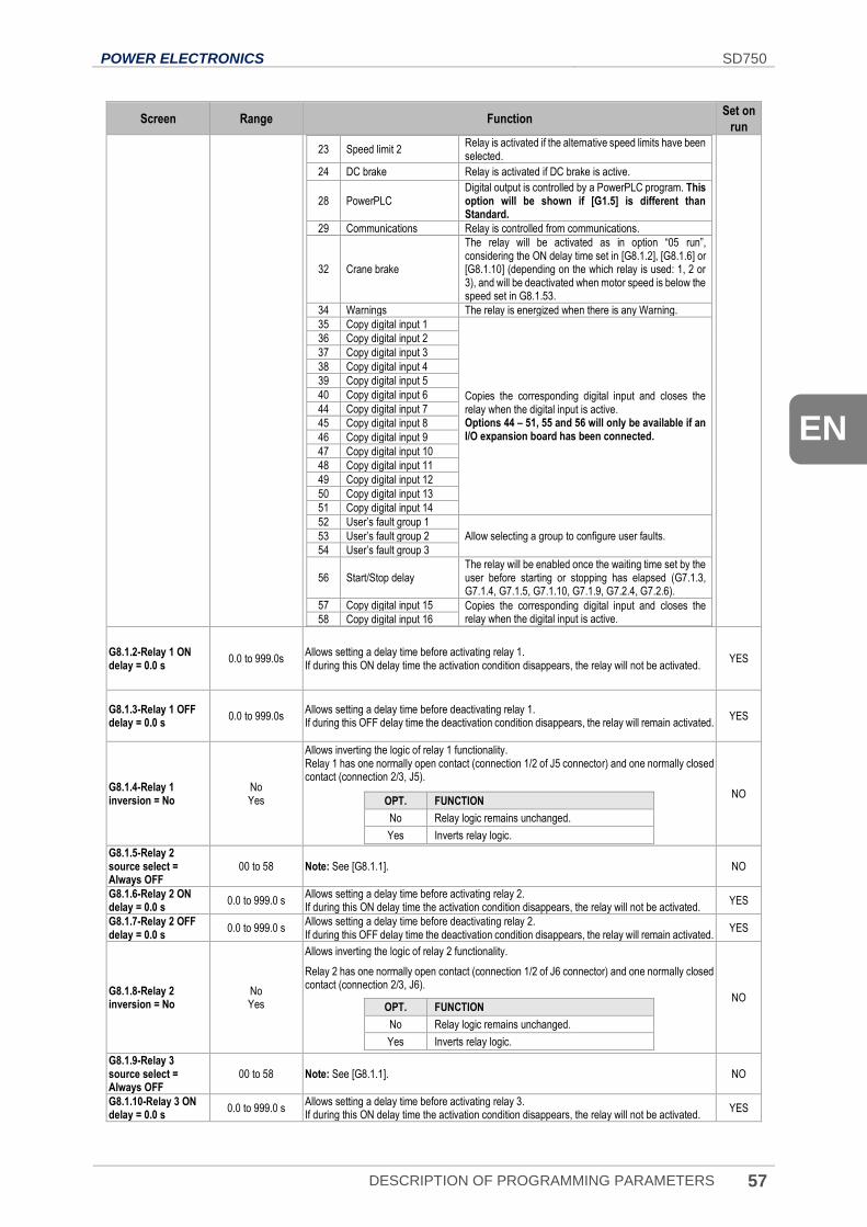
POWER ELECTRONICS SD750
DESCRIPTION OF PROGRAMMING PARAMETERS 57
EN
Screen Range Function Set on
run
23 Speed limit 2 Relay is activated if the alternative speed limits have been selected.
24 DC brake Relay is activated if DC brake is active.
28 PowerPLC Digital output is controlled by a PowerPLC program. This option will be shown if [G1.5] is different than Standard.
29 Communications Relay is controlled from communications.
32 Crane brake
The relay will be activated as in option “05 run”, considering the ON delay time set in [G8.1.2], [G8.1.6] or [G8.1.10] (depending on the which relay is used: 1, 2 or 3), and will be deactivated when motor speed is below the speed set in G8.1.53.
34 Warnings The relay is energized when there is any Warning.
35 Copy digital input 1
Copies the corresponding digital input and closes the relay when the digital input is active. Options 44 – 51, 55 and 56 will only be available if an I/O expansion board has been connected.
36 Copy digital input 2
37 Copy digital input 3
38 Copy digital input 4
39 Copy digital input 5
40 Copy digital input 6
44 Copy digital input 7
45 Copy digital input 8
46 Copy digital input 9
47 Copy digital input 10
48 Copy digital input 11
49 Copy digital input 12
50 Copy digital input 13
51 Copy digital input 14
52 User’s fault group 1
Allow selecting a group to configure user faults. 53 User’s fault group 2
54 User’s fault group 3
56 Start/Stop delay The relay will be enabled once the waiting time set by the user before starting or stopping has elapsed (G7.1.3, G7.1.4, G7.1.5, G7.1.10, G7.1.9, G7.2.4, G7.2.6).
57 Copy digital input 15 Copies the corresponding digital input and closes the relay when the digital input is active. 58 Copy digital input 16
G8.1.2-Relay 1 ON delay = 0.0 s
0.0 to 999.0s Allows setting a delay time before activating relay 1. If during this ON delay time the activation condition disappears, the relay will not be activated.
YES
G8.1.3-Relay 1 OFF delay = 0.0 s
0.0 to 999.0s Allows setting a delay time before deactivating relay 1. If during this OFF delay time the deactivation condition disappears, the relay will remain activated.
YES
G8.1.4-Relay 1 inversion = No
No Yes
Allows inverting the logic of relay 1 functionality. Relay 1 has one normally open contact (connection 1/2 of J5 connector) and one normally closed contact (connection 2/3, J5).
OPT. FUNCTION
No Relay logic remains unchanged.
Yes Inverts relay logic.
NO
G8.1.5-Relay 2 source select = Always OFF
00 to 58 Note: See [G8.1.1]. NO
G8.1.6-Relay 2 ON delay = 0.0 s
0.0 to 999.0 s Allows setting a delay time before activating relay 2. If during this ON delay time the activation condition disappears, the relay will not be activated.
YES
G8.1.7-Relay 2 OFF delay = 0.0 s
0.0 to 999.0 s Allows setting a delay time before deactivating relay 2. If during this OFF delay time the deactivation condition disappears, the relay will remain activated.
YES
G8.1.8-Relay 2 inversion = No
No Yes
Allows inverting the logic of relay 2 functionality.
Relay 2 has one normally open contact (connection 1/2 of J6 connector) and one normally closed contact (connection 2/3, J6).
OPT. FUNCTION
No Relay logic remains unchanged.
Yes Inverts relay logic.
NO
G8.1.9-Relay 3 source select = Always OFF
00 to 58 Note: See [G8.1.1]. NO
G8.1.10-Relay 3 ON delay = 0.0 s
0.0 to 999.0 s Allows setting a delay time before activating relay 3. If during this ON delay time the activation condition disappears, the relay will not be activated.
YES
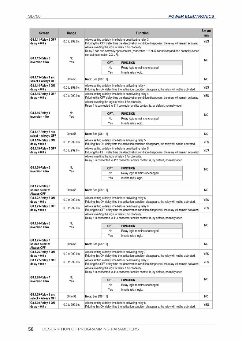
SD750 POWER ELECTRONICS
58 DESCRIPTION OF PROGRAMMING PARAMETERS
Screen Range Function Set on
run G8.1.11-Relay 3 OFF delay = 0.0 s
0.0 to 999.0 s Allows setting a delay time before deactivating relay 3. If during this OFF delay time the deactivation condition disappears, the relay will remain activated.
YES
G8.1.12-Relay 3 inversion = No
No Yes
Allows inverting the logic of relay 3 functionality. Relay 3 has one normally open contact (connection 1/2 of J7 connector) and one normally closed contact (connection 2/3, J7).
OPT. FUNCTION
No Relay logic remains unchanged.
Yes Inverts relay logic.
NO
G8.1.13-Relay 4 src select = Always OFF
00 to 58 Note: See [G8.1.1]. NO
G8.1.14-Relay 4 ON delay = 0.0 s
0.0 to 999.0 s Allows setting a delay time before activating relay 4. If during this ON delay time the activation condition disappears, the relay will not be activated.
YES
G8.1.15-Relay 4 OFF delay = 0.0 s
0.0 to 999.0 s Allows setting a delay time before deactivating relay 4. If during this OFF delay time the deactivation condition disappears, the relay will remain activated.
YES
G8.1.16-Relay 4 inversion = No
No Yes
Allows inverting the logic of relay 4 functionality. Relay 4 is connected to J11 connector and its contact is, by default, normally open.
OPT. FUNCTION
No Relay logic remains unchanged.
Yes Inverts relay logic.
NO
G8.1.17-Relay 5 src select = Always OFF
00 to 58 Note: See [G8.1.1]. NO
G8.1.18-Relay 5 ON delay = 0.0 s
0.0 to 999.0 s Allows setting a delay time before activating relay 5. If during this ON delay time the activation condition disappears, the relay will not be activated.
YES
G8.1.19-Relay 5 OFF delay = 0.0 s
0.0 to 999.0 s Allows setting a delay time before deactivating relay 5. If during this OFF delay time the deactivation condition disappears, the relay will remain activated.
YES
G8.1.20-Relay 5 inversion = No
No Yes
Allows inverting the logic of relay 5 functionality. Relay 5 is connected to J12 connector and its contact is, by default, normally open.
OPT. FUNCTION
No Relay logic remains unchanged.
Yes Inverts relay logic.
NO
G8.1.21-Relay 6 source select = Always OFF
00 to 58 Note: See [G8.1.1]. NO
G8.1.22-Relay 6 ON delay = 0.0 s
0.0 to 999.0 s Allows setting a delay time before activating relay 6. If during this ON delay time the activation condition disappears, the relay will not be activated.
YES
G8.1.23-Relay 6 OFF delay = 0.0 s
0.0 to 999.0 s Allows setting a delay time before deactivating relay 6. If during this OFF delay time the deactivation condition disappears, the relay will remain activated.
YES
G8.1.24-Relay 6 inversion = No
No Yes
Allows inverting the logic of relay 6 functionality. Relay 6 is connected to J13 connector and its contact is, by default, normally open.
OPT. FUNCTION
No Relay logic remains unchanged.
Yes Inverts relay logic.
NO
G8.1.25-Relay 7 source select = Always OFF
00 to 58 Note: See [G8.1.1]. NO
G8.1.26-Relay 7 ON delay = 0.0 s
0.0 to 999.0 s Allows setting a delay time before activating relay 7. If during this ON delay time the activation condition disappears, the relay will not be activated.
YES
G8.1.27-Relay 7 OFF delay = 0.0 s
0.0 to 999.0 s Allows setting a delay time before deactivating relay 7. If during this OFF delay time the deactivation condition disappears, the relay will remain activated.
YES
G8.1.28-Relay 7 inversion = No
No Yes
Allows inverting the logic of relay 7 functionality. Relay 7 is connected to J13 connector and its contact is, by default, normally open.
OPT. FUNCTION
No Relay logic remains unchanged.
Yes Inverts relay logic.
NO
G8.1.29-Relay 8 src select = Always OFF
00 to 58 Note: See [G8.1.1]. NO
G8.1.30-Relay 8 ON delay = 0.0 s
0.0 to 999.0 s Allows setting a delay time before activating relay 8. If during this ON delay time the activation condition disappears, the relay will not be activated.
YES
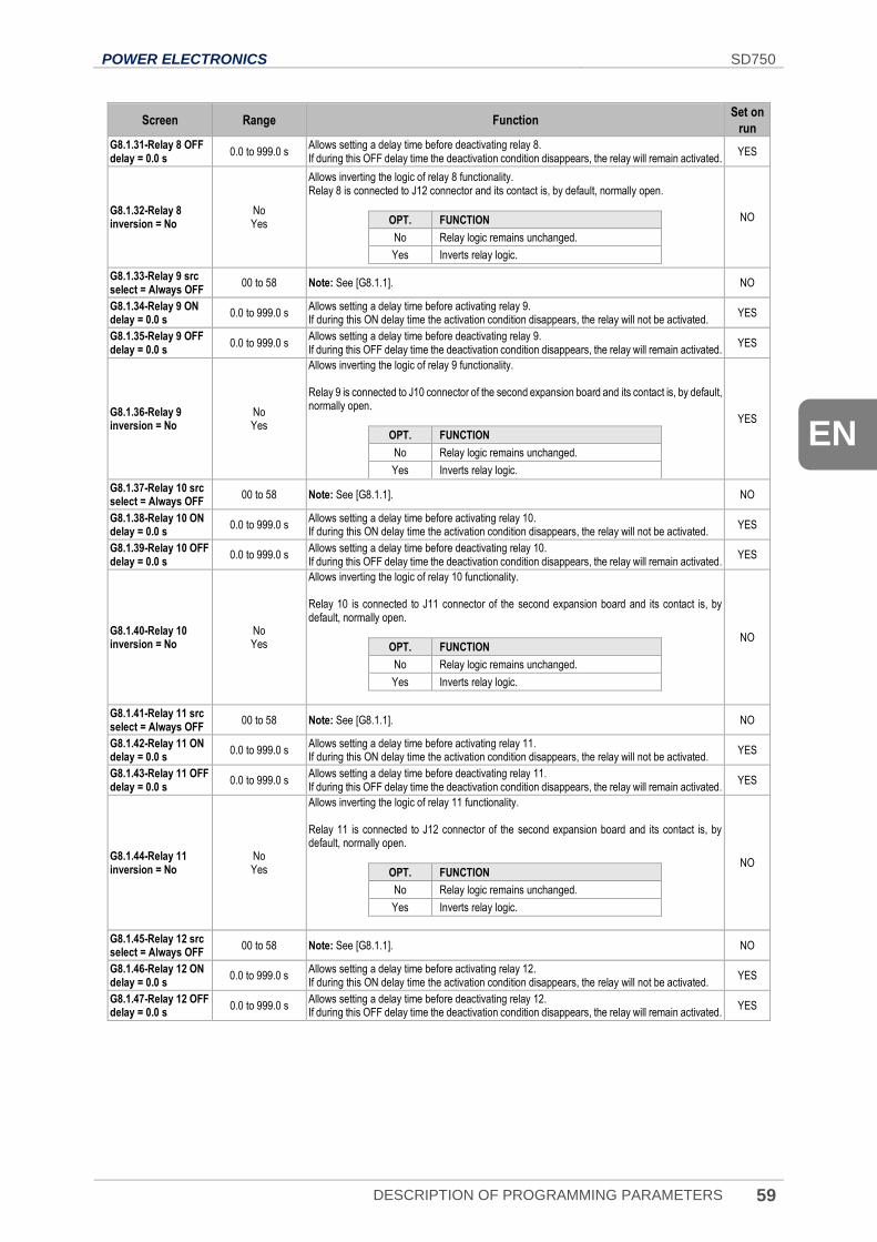
POWER ELECTRONICS SD750
DESCRIPTION OF PROGRAMMING PARAMETERS 59
EN
Screen Range Function Set on
run
G8.1.31-Relay 8 OFF delay = 0.0 s
0.0 to 999.0 s Allows setting a delay time before deactivating relay 8. If during this OFF delay time the deactivation condition disappears, the relay will remain activated.
YES
G8.1.32-Relay 8 inversion = No
No Yes
Allows inverting the logic of relay 8 functionality. Relay 8 is connected to J12 connector and its contact is, by default, normally open.
OPT. FUNCTION
No Relay logic remains unchanged.
Yes Inverts relay logic.
NO
G8.1.33-Relay 9 src select = Always OFF
00 to 58 Note: See [G8.1.1]. NO
G8.1.34-Relay 9 ON delay = 0.0 s
0.0 to 999.0 s Allows setting a delay time before activating relay 9. If during this ON delay time the activation condition disappears, the relay will not be activated.
YES
G8.1.35-Relay 9 OFF delay = 0.0 s
0.0 to 999.0 s Allows setting a delay time before deactivating relay 9. If during this OFF delay time the deactivation condition disappears, the relay will remain activated.
YES
G8.1.36-Relay 9 inversion = No
No Yes
Allows inverting the logic of relay 9 functionality. Relay 9 is connected to J10 connector of the second expansion board and its contact is, by default, normally open.
OPT. FUNCTION
No Relay logic remains unchanged.
Yes Inverts relay logic.
YES
G8.1.37-Relay 10 src select = Always OFF
00 to 58 Note: See [G8.1.1]. NO
G8.1.38-Relay 10 ON delay = 0.0 s
0.0 to 999.0 s Allows setting a delay time before activating relay 10. If during this ON delay time the activation condition disappears, the relay will not be activated.
YES
G8.1.39-Relay 10 OFF delay = 0.0 s
0.0 to 999.0 s Allows setting a delay time before deactivating relay 10. If during this OFF delay time the deactivation condition disappears, the relay will remain activated.
YES
G8.1.40-Relay 10 inversion = No
No Yes
Allows inverting the logic of relay 10 functionality. Relay 10 is connected to J11 connector of the second expansion board and its contact is, by default, normally open.
OPT. FUNCTION
No Relay logic remains unchanged.
Yes Inverts relay logic.
NO
G8.1.41-Relay 11 src select = Always OFF
00 to 58 Note: See [G8.1.1]. NO
G8.1.42-Relay 11 ON delay = 0.0 s
0.0 to 999.0 s Allows setting a delay time before activating relay 11. If during this ON delay time the activation condition disappears, the relay will not be activated.
YES
G8.1.43-Relay 11 OFF delay = 0.0 s
0.0 to 999.0 s Allows setting a delay time before deactivating relay 11. If during this OFF delay time the deactivation condition disappears, the relay will remain activated.
YES
G8.1.44-Relay 11 inversion = No
No Yes
Allows inverting the logic of relay 11 functionality. Relay 11 is connected to J12 connector of the second expansion board and its contact is, by default, normally open.
OPT. FUNCTION
No Relay logic remains unchanged.
Yes Inverts relay logic.
NO
G8.1.45-Relay 12 src select = Always OFF
00 to 58 Note: See [G8.1.1]. NO
G8.1.46-Relay 12 ON delay = 0.0 s
0.0 to 999.0 s Allows setting a delay time before activating relay 12. If during this ON delay time the activation condition disappears, the relay will not be activated.
YES
G8.1.47-Relay 12 OFF delay = 0.0 s
0.0 to 999.0 s Allows setting a delay time before deactivating relay 12. If during this OFF delay time the deactivation condition disappears, the relay will remain activated.
YES
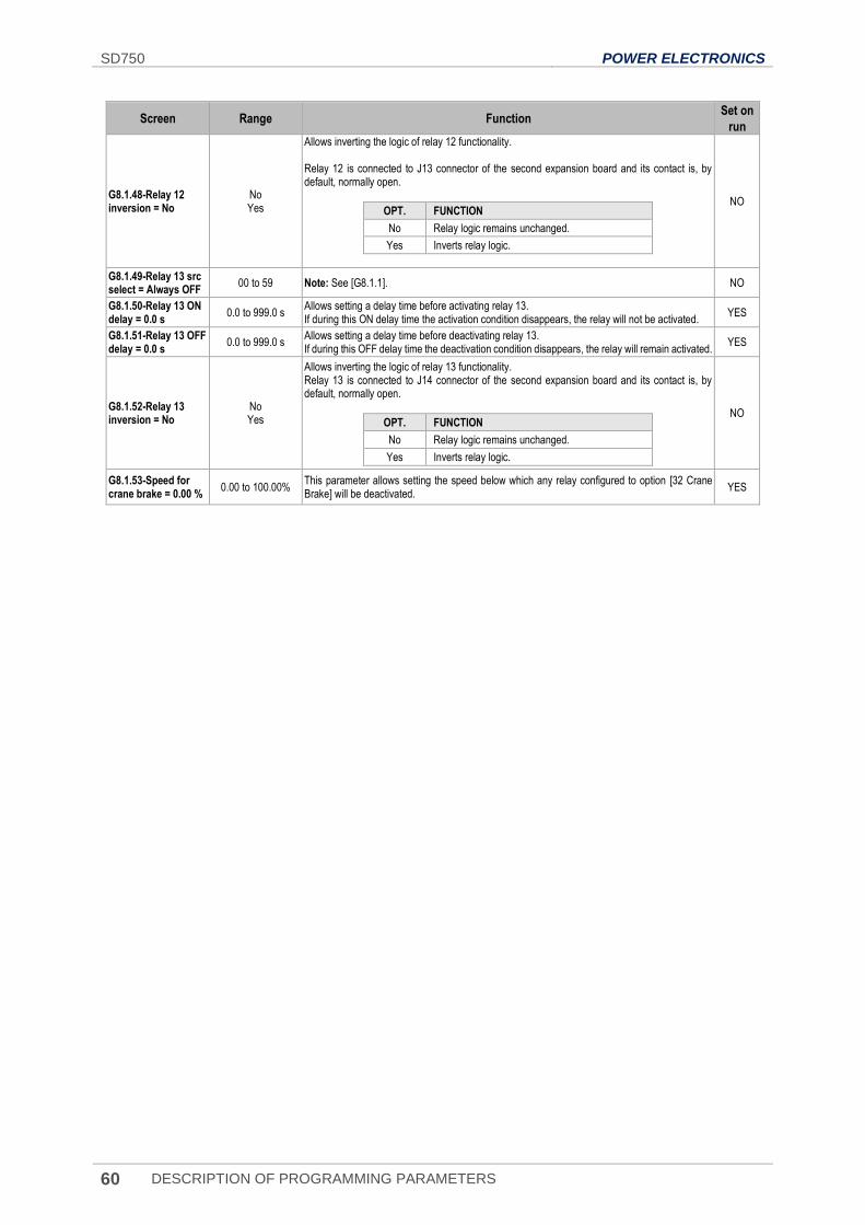
SD750 POWER ELECTRONICS
60 DESCRIPTION OF PROGRAMMING PARAMETERS
Screen Range Function Set on
run
G8.1.48-Relay 12 inversion = No
No Yes
Allows inverting the logic of relay 12 functionality. Relay 12 is connected to J13 connector of the second expansion board and its contact is, by default, normally open.
OPT. FUNCTION
No Relay logic remains unchanged.
Yes Inverts relay logic.
NO
G8.1.49-Relay 13 src select = Always OFF
00 to 59 Note: See [G8.1.1]. NO
G8.1.50-Relay 13 ON delay = 0.0 s
0.0 to 999.0 s Allows setting a delay time before activating relay 13. If during this ON delay time the activation condition disappears, the relay will not be activated.
YES
G8.1.51-Relay 13 OFF delay = 0.0 s
0.0 to 999.0 s Allows setting a delay time before deactivating relay 13. If during this OFF delay time the deactivation condition disappears, the relay will remain activated.
YES
G8.1.52-Relay 13 inversion = No
No Yes
Allows inverting the logic of relay 13 functionality. Relay 13 is connected to J14 connector of the second expansion board and its contact is, by default, normally open.
OPT. FUNCTION
No Relay logic remains unchanged.
Yes Inverts relay logic.
NO
G8.1.53-Speed for crane brake = 0.00 %
0.00 to 100.00% This parameter allows setting the speed below which any relay configured to option [32 Crane Brake] will be deactivated.
YES
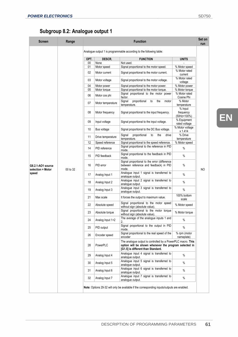
POWER ELECTRONICS SD750
DESCRIPTION OF PROGRAMMING PARAMETERS 61
EN
Subgroup 8.2: Analogue output 1
Screen Range Function Set on
run
G8.2.1-AO1 source selection = Motor speed
00 to 32
Analogue output 1 is programmable according to the following table:
OPT. DESCR. FUNCTION UNITS
00 None Not used. -
01 Motor speed Signal proportional to the motor speed. % Motor speed
02 Motor current Signal proportional to the motor current. % Motor rated
current
03 Motor voltage Signal proportional to the motor voltage. % Motor rated
voltage
04 Motor power Signal proportional to the motor power. % Motor power
05 Motor torque Signal proportional to the motor torque. % Motor torque
06 Motor cos phi Signal proportional to the motor power factor.
% Motor rated Cosine Phi
07 Motor temperature Signal proportional to the motor temperature.
% Motor temperature
08 Motor frequency Signal proportional to the input frequency. % Input
frequency (50Hz=100%)
09 Input voltage Signal proportional to the input voltage. % Equipment rated voltage
10 Bus voltage Signal proportional to the DC Bus voltage. % Motor voltage
x 1.414
11 Drive temperature Signal proportional to the drive temperature.
% Drive temperature
12 Speed reference Signal proportional to the speed reference. % Motor speed
14 PID reference Signal proportional to the reference in PID mode.
%
15 PID feedback Signal proportional to the feedback in PID mode.
%
16 PID error Signal proportional to the error (difference between reference and feedback) in PID mode.
%
17 Analog Input 1 Analogue input 1 signal is transferred to analogue output.
%
18 Analog Input 2 Analogue input 2 signal is transferred to analogue output.
%
19 Analog Input 3 Analogue input 3 signal is transferred to analogue output.
%
21 Max scale It forces the output to maximum value. 100% bottom
scale
22 Absolute speed Signal proportional to the motor speed without sign (absolute value).
% Motor speed
23 Absolute torque Signal proportional to the motor torque without sign (absolute value).
% Motor torque
24 Analog Input 1+2 The average of the analogue inputs 1 and 2.
%
25 PID output Signal proportional to the output in PID mode.
%
26 Encoder speed Signal proportional to the real speed of the encoder
% rpm (motor nameplate)
28 PowerPLC The analogue output is controlled by a PowerPLC macro. This option will be shown whenever the program selected in [G1.5] is different than Standard.
29 Analog Input 4 Analogue input 4 signal is transferred to analogue output.
%
30 Analog Input 5 Analogue input 5 signal is transferred to analogue output.
%
31 Analog Input 6 Analogue input 6 signal is transferred to analogue output.
%
32 Analog Input 7 Analogue input 7 signal is transferred to analogue output.
%
Note: Options 29-32 will only be available if the corresponding inputs/outputs are enabled.
NO
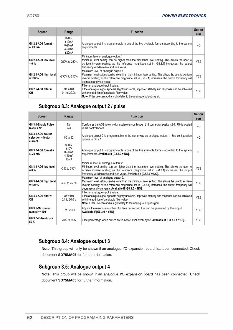
SD750 POWER ELECTRONICS
62 DESCRIPTION OF PROGRAMMING PARAMETERS
Screen Range Function Set on
run
G8.2.2-AO1 format = 4..20 mA
0-10V ±10mA 0-20mA 4-20mA ±20mA
Analogue output 1 is programmable in one of the five available formats according to the system requirements.
NO
G8.2.3-AO1 low level = 0 %
-250% to 250%
Minimum level of analogue output 1. Minimum level setting can be higher than the maximum level setting. This allows the user to achieve inverse scaling; as the reference magnitude set in [G8.2.1] increases, the output frequency will decrease and vice versa.
YES
G8.2.4-AO1 high level = 100 %
-250% to 250%
Maximum level of analogue output 1. Maximum level setting can be lower than the minimum level setting. This allows the user to achieve inverse scaling; as the reference magnitude set in [G8.2.1] increases, the output frequency will decrease and vice versa.
YES
G8.2.5-AO1 filter = Off
Off = 0.0 0.1 to 20.0s
Filter for analogue input 1 value. If the analogue signal appears slightly unstable, improved stability and response can be achieved with the addition of a suitable filter value. Note: Filter use can add a slight delay to the analogue output signal.
YES
Subgroup 8.3: Analogue output 2 / pulse
Screen Range Function Set on
run
G8.3.0-Enable Pulse Mode = No
No Yes
Configures the AO2 to work with a pulse sensor through J18 connector, position 2-1. J18 is located in the control board.
NO
G8.3.1-AO2 source selection = Motor current
00 to 32 Analogue output 2 is programmable in the same way as analogue output 1. See configuration options in G8.2.1.
NO
G8.3.2-AO2 format = 4..20 mA
0-10V ±10V
0-20mA 4-20mA 10mA
Analogue output 2 is programmable in one of the five available formats according to the system requirements. Available if [G8.3.0 = NO].
NO
G8.3.3-AO2 low level = 0 %
-250 to 250%
Minimum level of analogue output 2. Minimum level setting can be higher than the maximum level setting. This allows the user to achieve inverse scaling; as the reference magnitude set in [G8.3.1] increases, the output frequency will decrease and vice versa. Available if [G8.3.0 = NO].
YES
G8.3.4-AO2 high level = 100 %
-250 to 250%
Maximum level of analogue output 2. Maximum level setting can be lower than the minimum level setting. This allows the user to achieve inverse scaling; as the reference magnitude set in [G8.3.1] increases, the output frequency will decrease and vice versa. Available if [G8.3.0 = NO].
YES
G8.3.5-AO2 filter = Off
Off = 0.0 0.1 to 20.0 s
Filter for analogue input 2 value. If the analogue signal appears slightly unstable, improved stability and response can be achieved with the addition of a suitable filter value. Note: Filter use can add a slight delay to the analogue output signal.
YES
G8.3.6-Max pulse number = 100
0 to 32000 Adjusts the maximum number of pulses per second that can be generated by the output. Available if [G8.3.0 = YES].
YES
G8.3.7-Pulse duty = 50 %
20% to 65% Time percentage when pulses are in active level. Work cycle. Available if [G8.3.0 = YES]. YES
Subgroup 8.4: Analogue output 3
Note: This group will only be shown if an analogue I/O expansion board has been connected. Check
document SD75MA05 for further information.
Subgroup 8.5: Analogue output 4
Note: This group will be shown if an analogue I/O expansion board has been connected. Check
document SD75MA05 for further information.
POWER ELECTRONICS SD750
DESCRIPTION OF PROGRAMMING PARAMETERS 63
EN
Subgroup 8.6: Analogue output 5
Note: This group will be shown if an analogue I/O expansion board has been connected. Check
document SD75MA05 for further information.
Subgroup 8.7: Analogue output 6
Note: This group will be shown if an analogue I/O expansion board has been connected. Check
document SD75MA05 for further information.
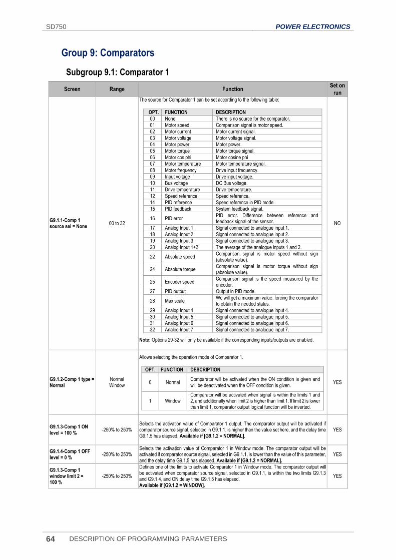
SD750 POWER ELECTRONICS
64 DESCRIPTION OF PROGRAMMING PARAMETERS
Group 9: Comparators
Subgroup 9.1: Comparator 1
Screen Range Function Set on
run
G9.1.1-Comp 1 source sel = None
00 to 32
The source for Comparator 1 can be set according to the following table:
OPT. FUNCTION DESCRIPTION
00 None There is no source for the comparator.
01 Motor speed Comparison signal is motor speed.
02 Motor current Motor current signal.
03 Motor voltage Motor voltage signal.
04 Motor power Motor power.
05 Motor torque Motor torque signal.
06 Motor cos phi Motor cosine phi
07 Motor temperature Motor temperature signal.
08 Motor frequency Drive input frequency.
09 Input voltage Drive input voltage.
10 Bus voltage DC Bus voltage.
11 Drive temperature Drive temperature.
12 Speed reference Speed reference.
14 PID reference Speed reference in PID mode.
15 PID feedback System feedback signal.
16 PID error PID error. Difference between reference and feedback signal of the sensor.
17 Analog Input 1 Signal connected to analogue input 1.
18 Analog Input 2 Signal connected to analogue input 2.
19 Analog Input 3 Signal connected to analogue input 3.
20 Analog Input 1+2 The average of the analogue inputs 1 and 2.
22 Absolute speed Comparison signal is motor speed without sign (absolute value).
24 Absolute torque Comparison signal is motor torque without sign (absolute value).
25 Encoder speed Comparison signal is the speed measured by the encoder.
27 PID output Output in PID mode.
28 Max scale We will get a maximum value, forcing the comparator to obtain the needed status.
29 Analog Input 4 Signal connected to analogue input 4.
30 Analog Input 5 Signal connected to analogue input 5.
31 Analog Input 6 Signal connected to analogue input 6.
32 Analog Input 7 Signal connected to analogue input 7.
Note: Options 29-32 will only be available if the corresponding inputs/outputs are enabled.
NO
G9.1.2-Comp 1 type = Normal
Normal Window
Allows selecting the operation mode of Comparator 1.
OPT. FUNCTION DESCRIPTION
0 Normal Comparator will be activated when the ON condition is given and will be deactivated when the OFF condition is given.
1 Window Comparator will be activated when signal is within the limits 1 and 2, and additionally when limit 2 is higher than limit 1. If limit 2 is lower than limit 1, comparator output logical function will be inverted.
YES
G9.1.3-Comp 1 ON level = 100 %
-250% to 250% Selects the activation value of Comparator 1 output. The comparator output will be activated if comparator source signal, selected in G9.1.1, is higher than the value set here, and the delay time G9.1.5 has elapsed. Available if [G9.1.2 = NORMAL].
YES
G9.1.4-Comp 1 OFF level = 0 %
-250% to 250% Selects the activation value of Comparator 1 in Window mode. The comparator output will be activated if comparator source signal, selected in G9.1.1, is lower than the value of this parameter, and the delay time G9.1.5 has elapsed. Available if [G9.1.2 = NORMAL].
YES
G9.1.3-Comp 1 window limit 2 = 100 %
-250% to 250%
Defines one of the limits to activate Comparator 1 in Window mode. The comparator output will be activated when comparator source signal, selected in G9.1.1, is within the two limits G9.1.3 and G9.1.4, and ON delay time G9.1.5 has elapsed. Available if [G9.1.2 = WINDOW].
YES
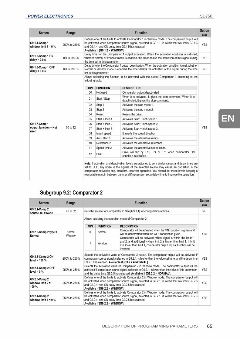
POWER ELECTRONICS SD750
DESCRIPTION OF PROGRAMMING PARAMETERS 65
EN
Screen Range Function Set on
run
G9.1.4-Comp 1 window limit 1 = 0 %
-250% to 250%
Defines one of the limits to activate Comparator 1 in Window mode. The comparator output will be activated when comparator source signal, selected in G9.1.1, is within the two limits G9.1.3 and G9.1.4, and ON delay time G9.1.5 has elapsed. Available if [G9.1.2 = WINDOW].
YES
G9.1.5-Comp 1 ON delay = 0.0 s
0.0 to 999.0s Delay time for the Comparator 1 output activation. When the activation condition is satisfied, whether Normal or Window mode is enabled, the timer delays the activation of this signal during the time set in this parameter.
NO
G9.1.6-Comp 1 OFF delay = 0.0 s
0.0 to 999.0s Delay time for the Comparator 1 output deactivation. When the activation condition is met, whether Normal or Window mode is enabled, the timer delays the activation of this signal during the time set in this parameter.
NO
G9.1.7-Comp 1 output function = Not used
00 to 12
Allows selecting the function to be activated with the output Comparator 1 according to the following table:
OPT. FUNCTION DESCRIPTION
00 Not used Comparator output deactivated
01 Start / Stop When it is activated, it gives the start command. When it is deactivated, it gives the stop command.
02 Stop 1 Activates the stop mode 1.
03 Stop 2 Activates the stop mode 2.
04 Reset Resets the drive.
05 Start + Inch 1 Activates Start + Inch speed 1.
06 Start + Inch 2 Activates Start + Inch speed 2.
07 Start + Inch 3 Activates Start + Inch speed 3.
08 Invert speed It inverts the speed direction.
09 Acc / Dec 2 Activates the alternative ramps.
10 Reference 2 Activates the alternative reference.
11 Speed limit 2 Activates the alternative speed limits.
12 Fault Drive will trip by F73, F74 or F75 when comparator ON condition is satisfied.
Note: If activation and deactivation levels are adjusted to very similar values and delay times are set to OFF, any noise in the signals of the selected source may cause an oscillation in the comparator activation and, therefore, incorrect operation. You should set these levels keeping a reasonable margin between them, and if necessary, set a delay time to improve the operation.
YES
Subgroup 9.2: Comparator 2
Screen Range Function Set on
run G9.2.1-Comp 2 source sel = None
00 to 32 Sets the source for Comparator 2. See [G9.1.1] for configuration options. NO
G9.2.2-Comp 2 type = Normal
Normal Window
Allows selecting the operation mode of Comparator 2.
OPT. FUNCTION DESCRIPTION
0 Normal Comparator will be activated when the ON condition is given and will be deactivated when the OFF condition is given.
1 Window
Comparator will be activated when signal is within the limits 1 and 2, and additionally when limit 2 is higher than limit 1. If limit 2 is lower than limit 1, comparator output logical function will be inverted.
YES
G9.2.3-Comp 2 ON level = 100 %
-250% to 250% Selects the activation value of Comparator 2 output. The comparator output will be activated if comparator source signal, selected in G9.2.1, is higher than the value set here, and the delay time G9.2.5 has elapsed. Available if [G9.2.2 = NORMAL].
YES
G9.2.4-Comp 2 OFF level = 0 %
-250% to 250% Selects the activation value of Comparator 2 in Window mode. The comparator output will be activated if comparator source signal, selected in G9.2.1, is lower than the value of this parameter, and the delay time G9.2.5 has elapsed. Available if [G9.2.2 = NORMAL].
YES
G9.2.3-Comp 2 window limit 2 = 100 %
-250% to 250%
Defines one of the limits to activate Comparator 2 in Window mode. The comparator output will be activated when comparator source signal, selected in G9.2.1, is within the two limits G9.2.3 and G9.2.4, and ON delay time G9.2.5 has elapsed. Available if [G9.2.2 = WINDOW].
YES
G9.2.4-Comp 2 window limit 1 = 0 %
-250% to 250%
Defines one of the limits to activate Comparator 2 in Window mode. The comparator output will be activated when comparator source signal, selected in G9.2.1, is within the two limits G9.2.3 and G9.2.4, and ON delay time G9.2.5 has elapsed. Available if [G9.2.2 = WINDOW].
YES
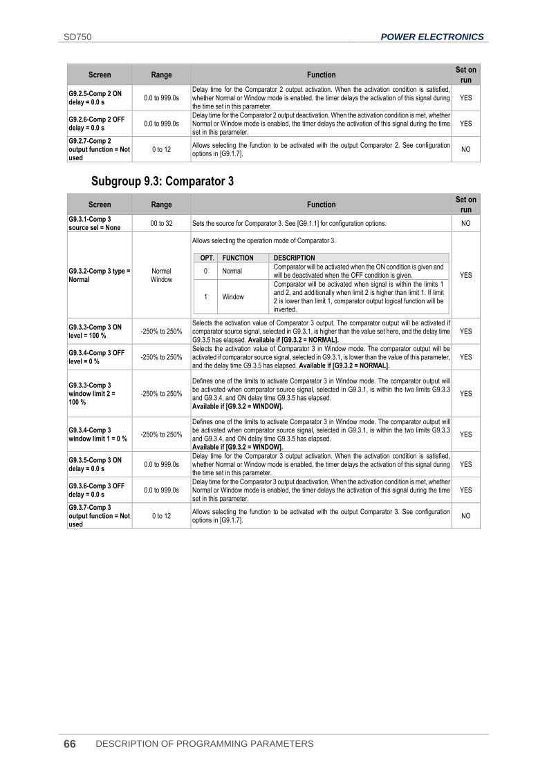
SD750 POWER ELECTRONICS
66 DESCRIPTION OF PROGRAMMING PARAMETERS
Screen Range Function Set on
run
G9.2.5-Comp 2 ON delay = 0.0 s
0.0 to 999.0s Delay time for the Comparator 2 output activation. When the activation condition is satisfied, whether Normal or Window mode is enabled, the timer delays the activation of this signal during the time set in this parameter.
YES
G9.2.6-Comp 2 OFF delay = 0.0 s
0.0 to 999.0s Delay time for the Comparator 2 output deactivation. When the activation condition is met, whether Normal or Window mode is enabled, the timer delays the activation of this signal during the time set in this parameter.
YES
G9.2.7-Comp 2 output function = Not used
0 to 12 Allows selecting the function to be activated with the output Comparator 2. See configuration options in [G9.1.7].
NO
Subgroup 9.3: Comparator 3
Screen Range Function Set on
run G9.3.1-Comp 3 source sel = None
00 to 32 Sets the source for Comparator 3. See [G9.1.1] for configuration options. NO
G9.3.2-Comp 3 type = Normal
Normal Window
Allows selecting the operation mode of Comparator 3.
OPT. FUNCTION DESCRIPTION
0 Normal Comparator will be activated when the ON condition is given and will be deactivated when the OFF condition is given.
1 Window
Comparator will be activated when signal is within the limits 1 and 2, and additionally when limit 2 is higher than limit 1. If limit 2 is lower than limit 1, comparator output logical function will be inverted.
YES
G9.3.3-Comp 3 ON level = 100 %
-250% to 250% Selects the activation value of Comparator 3 output. The comparator output will be activated if comparator source signal, selected in G9.3.1, is higher than the value set here, and the delay time G9.3.5 has elapsed. Available if [G9.3.2 = NORMAL].
YES
G9.3.4-Comp 3 OFF level = 0 %
-250% to 250% Selects the activation value of Comparator 3 in Window mode. The comparator output will be activated if comparator source signal, selected in G9.3.1, is lower than the value of this parameter, and the delay time G9.3.5 has elapsed. Available if [G9.3.2 = NORMAL].
YES
G9.3.3-Comp 3 window limit 2 = 100 %
-250% to 250%
Defines one of the limits to activate Comparator 3 in Window mode. The comparator output will be activated when comparator source signal, selected in G9.3.1, is within the two limits G9.3.3 and G9.3.4, and ON delay time G9.3.5 has elapsed. Available if [G9.3.2 = WINDOW].
YES
G9.3.4-Comp 3 window limit 1 = 0 %
-250% to 250%
Defines one of the limits to activate Comparator 3 in Window mode. The comparator output will be activated when comparator source signal, selected in G9.3.1, is within the two limits G9.3.3 and G9.3.4, and ON delay time G9.3.5 has elapsed. Available if [G9.3.2 = WINDOW].
YES
G9.3.5-Comp 3 ON delay = 0.0 s
0.0 to 999.0s Delay time for the Comparator 3 output activation. When the activation condition is satisfied, whether Normal or Window mode is enabled, the timer delays the activation of this signal during the time set in this parameter.
YES
G9.3.6-Comp 3 OFF delay = 0.0 s
0.0 to 999.0s Delay time for the Comparator 3 output deactivation. When the activation condition is met, whether Normal or Window mode is enabled, the timer delays the activation of this signal during the time set in this parameter.
YES
G9.3.7-Comp 3 output function = Not used
0 to 12 Allows selecting the function to be activated with the output Comparator 3. See configuration options in [G9.1.7].
NO
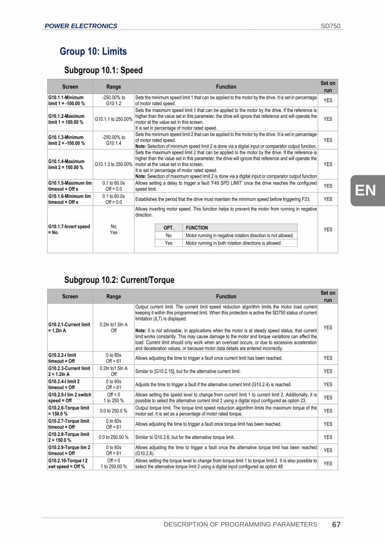
POWER ELECTRONICS SD750
DESCRIPTION OF PROGRAMMING PARAMETERS 67
EN
Group 10: Limits
Subgroup 10.1: Speed
Screen Range Function Set on
run
G10.1.1-Minimum limit 1 = -100.00 %
-250.00% to G10.1.2
Sets the minimum speed limit 1 that can be applied to the motor by the drive. It is set in percentage of motor rated speed.
YES
G10.1.2-Maximum limit 1 = 100.00 %
G10.1.1 to 250.00%
Sets the maximum speed limit 1 that can be applied to the motor by the drive. If the reference is higher than the value set in this parameter, the drive will ignore that reference and will operate the motor at the value set in this screen. It is set in percentage of motor rated speed.
YES
G10.1.3-Minimum limit 2 = -100.00 %
-250.00% to G10.1.4
Sets the minimum speed limit 2 that can be applied to the motor by the drive. It is set in percentage of motor rated speed. Note: Selection of minimum speed limit 2 is done via a digital input or comparator output function.
YES
G10.1.4-Maximum limit 2 = 100.00 %
G10.1.3 to 250.00%
Sets the maximum speed limit 2 that can be applied to the motor by the drive. If the reference is higher than the value set in this parameter, the drive will ignore that reference and will operate the motor at the value set in this screen. It is set in percentage of motor rated speed. Note: Selection of maximum speed limit 2 is done via a digital input or comparator output function
YES
G10.1.5-Maximum lim timeout = Off s
0.1 to 60.0s Off = 0.0
Allows setting a delay to trigger a fault 'F49 SPD LIMIT' once the drive reaches the configured speed limit.
YES
G10.1.6-Minimum lim timeout = Off s
0.1 to 60.0s Off = 0.0
Establishes the period that the drive must maintain the minimum speed before triggering F23. YES
G10.1.7-Invert speed = No
No Yes
Allows inverting motor speed. This function helps to prevent the motor from running in negative direction.
OPT. FUNCTION
No Motor running in negative rotation direction is not allowed.
Yes Motor running in both rotation directions is allowed.
YES
Subgroup 10.2: Current/Torque
Screen Range Function Set on
run
G10.2.1-Current limit = 1.2In A
0.2In to1.5In A Off
Output current limit. The current limit speed reduction algorithm limits the motor load current keeping it within this programmed limit. When this protection is active the SD750 status of current limitation (ILT) is displayed. Note: It is not advisable, in applications when the motor is at steady speed status, that current limit works constantly. This may cause damage to the motor and torque variations can affect the load. Current limit should only work when an overload occurs, or due to excessive acceleration and deceleration values, or because motor data details are entered incorrectly.
YES
G10.2.2-I limit timeout = Off
0 to 60s Off = 61
Allows adjusting the time to trigger a fault once current limit has been reached. YES
G10.2.3-Current limit 2 = 1.2In A
0.2In to1.5In A Off
Similar to [G10.2.15], but for the alternative current limit. YES
G10.2.4-I limit 2 timeout = Off
0 to 60s Off = 61
Adjusts the time to trigger a fault if the alternative current limit (G10.2.4) is reached. YES
G10.2.5-I lim 2 switch speed = Off
Off = 0 1 to 250 %
Allows setting the speed level to change from current limit 1 to current limit 2. Additionally, it is possible to select the alternative current limit 2 using a digital input configured as option 23.
YES
G10.2.6-Torque limit = 150.0 %
0.0 to 250.0 % Output torque limit. The torque limit speed reduction algorithm limits the maximum torque of the motor set. It is set as a percentage of motor rated torque.
YES
G10.2.7-Torque limit timeout = Off
0 to 60s Off = 61
Allows adjusting the time to trigger a fault once torque limit has been reached. YES
G10.2.8-Torque limit 2 = 150.0 %
0.0 to 250.00 % Similar to G10.2.6, but for the alternative torque limit. YES
G10.2.9-Torque lim 2 timeout = Off
0 to 60s Off = 61
Allows adjusting the time to trigger a fault once the alternative torque limit has been reached (G10.2.8).
YES
G10.2.10-Torque l 2 swt speed = Off %
Off = 0 1 to 250.00 %
Allows setting the torque level to change from torque limit 1 to torque limit 2. It is also possible to select the alternative torque limit 2 using a digital input configured as option 48.
YES
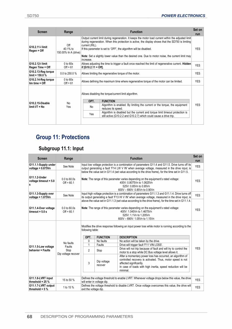
SD750 POWER ELECTRONICS
68 DESCRIPTION OF PROGRAMMING PARAMETERS
Screen Range Function Set on
run
G10.2.11-I limit Regen = Off
Off 40.1% to
150.00%·In A (drive)
Output current limit during regeneration. It keeps the motor load current within the adjusted limit during regeneration. When this protection is active, the display shows that the SD750 is limiting current (RIL). If this parameter is set to ‘OFF’, the algorithm will be disabled. Note: Set a slightly lower value than the desired one. Due to motor noise, the current limit may increase.
YES
G10.2.12-I limit Regen Time = Off
0 to 60s Off = 61
Allows adjusting the time to trigger a fault once reached the limit of regenerative current. Hidden if [G10.2.11 = Off].
YES
G10.2.13-Reg torque limit = 150.0 %
0.0 to 250.0 % Allows limiting the regenerative torque of the motor. YES
G10.2.14-Reg torque lim time = Off
0 to 60s Off = 61
Allows defining the maximum time where regenerative torque of the motor can be limited. YES
G10.2.15-Disable limit I/T = No
No Yes
Allows disabling the torque/current limit algorithm.
OPT. FUNCTION
No Algorithm is enabled. By limiting the current or the torque, the equipment reduces its speed.
Yes Algorithm is disabled but the current and torque limit timeout protection is still active (G10.2.2 and G10.2.7) which could cause a drive trip.
YES
Group 11: Protections
Subgroup 11.1: Input
Screen Range Function Set on
run G11.1.1-Supply under voltage = 0.875Vn
See Note Input low voltage protection is a combination of parameters G11.4 and G11.5. Drive turns off its output generating a fault 'F14 LW V IN' when average voltage, measured in the drive input, is below the value set in G11.4 (set value according to the drive frame), for the time set in G11.5. Note: The range of this parameter varies depending on the equipment’s rated voltage:
400V: 0.8075Vn to 1.0625Vn 525V: 0.85Vn to 0.95Vn
600V – 690V: 0.85Vn to 0.90Vn
YES
G11.1.2-Under voltage timeout = 5.0 s
0.0 to 60.0s Off = 60.1
YES
G11.1.3-Supply over voltage = 1.075Vn
See Note Input high voltage protection is a combination of parameters G11.1.3 and G11.1.4. Drive turns off its output generating a fault 'F13 HI V IN' when average voltage, measured in the drive input, is above the value set in G11.1.3 (set value according to the drive frame), for the time set in G11.1.4. Note: The range of this parameter varies depending on the equipment’s rated voltage:
400V: 1.045Vn to 1.4675Vn 525V: 1.1Vn to 1.205Vn
600V – 690V: 1.05Vn to 1.15Vn
YES
G11.1.4-Over voltage timeout = 5.0 s
0.0 to 60.0s Off = 60.1
YES
G11.1.5-Low voltage behavior = Faults
No faults Faults Stop
Dip voltage recover
Modifies the drive response following an input power loss while motor is running according to the following table:
OPT. FUNCTION DESCRIPTION
0 No faults No action will be taken by the drive.
1 Faults Drive will trigger fault 'F11 VIN LOSS'.
2 Stop Drive will not trip because of fault and will try to control the motor to a stop while DC Bus voltage level allows it.
3 Dip voltage recover
After a momentary power loss has occurred, an algorithm of controlled recovery is activated. Thus, motor speed is not affected significantly. In case of loads with high inertia, speed reduction will be minimal.
YES
G11.1.6-LVRT input threshold = 25 %
15 to 50 % Defines the voltage threshold to enable LVRT. Whenever voltage drops below this value, the drive will enter in voltage dip.
YES
G11.1.7-LVRT output threshold = 5 %
1 to 15 % Defines the voltage threshold to disable LVRT. Once voltage overcomes this value, the drive will exit the voltage dip.
YES
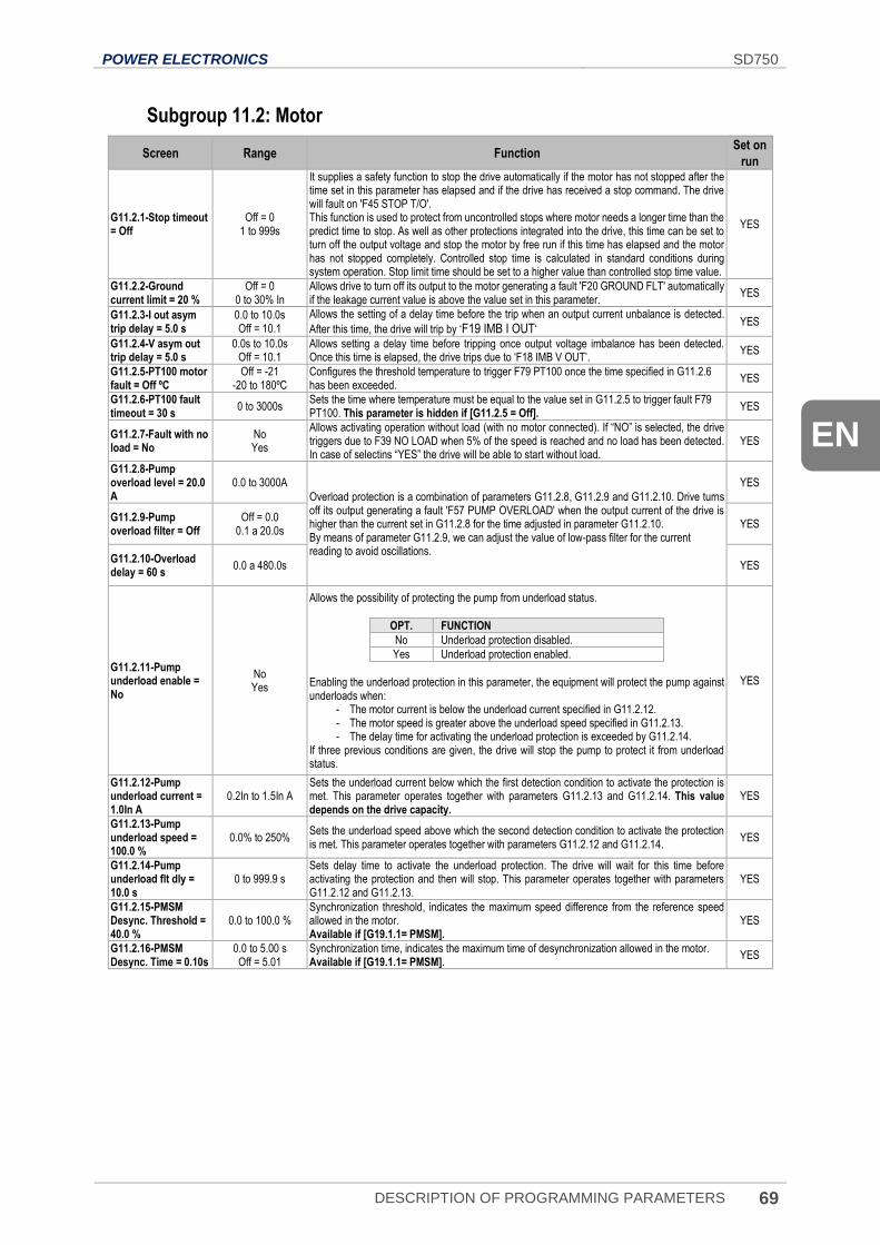
POWER ELECTRONICS SD750
DESCRIPTION OF PROGRAMMING PARAMETERS 69
EN
Subgroup 11.2: Motor
Screen Range Function Set on
run
G11.2.1-Stop timeout = Off
Off = 0 1 to 999s
It supplies a safety function to stop the drive automatically if the motor has not stopped after the time set in this parameter has elapsed and if the drive has received a stop command. The drive will fault on 'F45 STOP T/O'. This function is used to protect from uncontrolled stops where motor needs a longer time than the predict time to stop. As well as other protections integrated into the drive, this time can be set to turn off the output voltage and stop the motor by free run if this time has elapsed and the motor has not stopped completely. Controlled stop time is calculated in standard conditions during system operation. Stop limit time should be set to a higher value than controlled stop time value.
YES
G11.2.2-Ground current limit = 20 %
Off = 0 0 to 30% In
Allows drive to turn off its output to the motor generating a fault 'F20 GROUND FLT' automatically if the leakage current value is above the value set in this parameter.
YES
G11.2.3-I out asym trip delay = 5.0 s
0.0 to 10.0s Off = 10.1
Allows the setting of a delay time before the trip when an output current unbalance is detected.
After this time, the drive will trip by ‘F19 IMB I OUT‘ YES
G11.2.4-V asym out trip delay = 5.0 s
0.0s to 10.0s Off = 10.1
Allows setting a delay time before tripping once output voltage imbalance has been detected. Once this time is elapsed, the drive trips due to ‘F18 IMB V OUT’.
YES
G11.2.5-PT100 motor fault = Off ºC
Off = -21 -20 to 180ºC
Configures the threshold temperature to trigger F79 PT100 once the time specified in G11.2.6 has been exceeded.
YES
G11.2.6-PT100 fault timeout = 30 s
0 to 3000s Sets the time where temperature must be equal to the value set in G11.2.5 to trigger fault F79 PT100. This parameter is hidden if [G11.2.5 = Off].
YES
G11.2.7-Fault with no load = No
No Yes
Allows activating operation without load (with no motor connected). If “NO” is selected, the drive triggers due to F39 NO LOAD when 5% of the speed is reached and no load has been detected. In case of selectins “YES” the drive will be able to start without load.
YES
G11.2.8-Pump overload level = 20.0 A
0.0 to 3000A
Overload protection is a combination of parameters G11.2.8, G11.2.9 and G11.2.10. Drive turns off its output generating a fault 'F57 PUMP OVERLOAD' when the output current of the drive is higher than the current set in G11.2.8 for the time adjusted in parameter G11.2.10. By means of parameter G11.2.9, we can adjust the value of low-pass filter for the current reading to avoid oscillations.
YES
G11.2.9-Pump overload filter = Off
Off = 0.0 0.1 a 20.0s
YES
G11.2.10-Overload delay = 60 s
0.0 a 480.0s YES
G11.2.11-Pump underload enable = No
No Yes
Allows the possibility of protecting the pump from underload status.
OPT. FUNCTION
No Underload protection disabled.
Yes Underload protection enabled.
Enabling the underload protection in this parameter, the equipment will protect the pump against underloads when:
- The motor current is below the underload current specified in G11.2.12. - The motor speed is greater above the underload speed specified in G11.2.13. - The delay time for activating the underload protection is exceeded by G11.2.14.
If three previous conditions are given, the drive will stop the pump to protect it from underload status.
YES
G11.2.12-Pump underload current = 1.0In A
0.2In to 1.5In A Sets the underload current below which the first detection condition to activate the protection is met. This parameter operates together with parameters G11.2.13 and G11.2.14. This value depends on the drive capacity.
YES
G11.2.13-Pump underload speed = 100.0 %
0.0% to 250% Sets the underload speed above which the second detection condition to activate the protection is met. This parameter operates together with parameters G11.2.12 and G11.2.14.
YES
G11.2.14-Pump underload flt dly = 10.0 s
0 to 999.9 s Sets delay time to activate the underload protection. The drive will wait for this time before activating the protection and then will stop. This parameter operates together with parameters G11.2.12 and G11.2.13.
YES
G11.2.15-PMSM Desync. Threshold = 40.0 %
0.0 to 100.0 % Synchronization threshold, indicates the maximum speed difference from the reference speed allowed in the motor. Available if [G19.1.1= PMSM].
YES
G11.2.16-PMSM Desync. Time = 0.10s
0.0 to 5.00 s Off = 5.01
Synchronization time, indicates the maximum time of desynchronization allowed in the motor. Available if [G19.1.1= PMSM].
YES
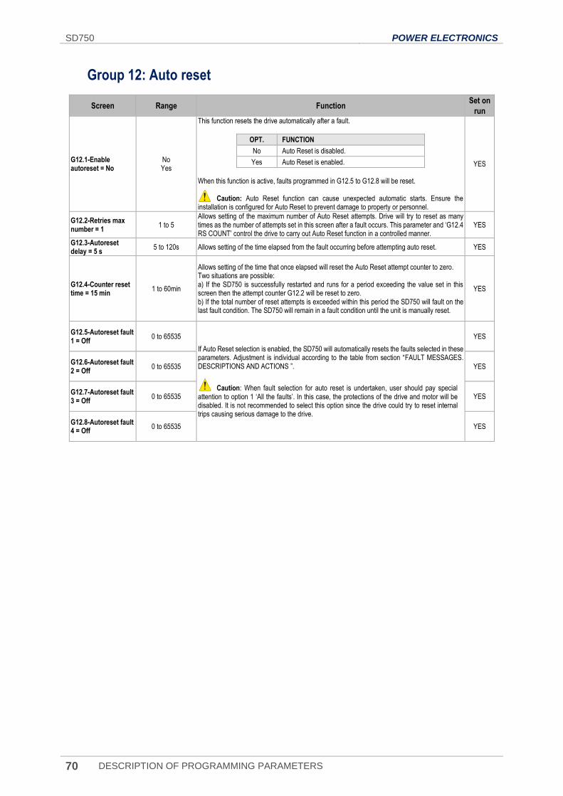
SD750 POWER ELECTRONICS
70 DESCRIPTION OF PROGRAMMING PARAMETERS
Group 12: Auto reset
Screen Range Function Set on
run
G12.1-Enable autoreset = No
No Yes
This function resets the drive automatically after a fault.
OPT. FUNCTION
No Auto Reset is disabled.
Yes Auto Reset is enabled.
When this function is active, faults programmed in G12.5 to G12.8 will be reset. Caution: Auto Reset function can cause unexpected automatic starts. Ensure the installation is configured for Auto Reset to prevent damage to property or personnel.
YES
G12.2-Retries max number = 1
1 to 5 Allows setting of the maximum number of Auto Reset attempts. Drive will try to reset as many times as the number of attempts set in this screen after a fault occurs. This parameter and ‘G12.4 RS COUNT’ control the drive to carry out Auto Reset function in a controlled manner.
YES
G12.3-Autoreset delay = 5 s
5 to 120s Allows setting of the time elapsed from the fault occurring before attempting auto reset. YES
G12.4-Counter reset time = 15 min
1 to 60min
Allows setting of the time that once elapsed will reset the Auto Reset attempt counter to zero. Two situations are possible: a) If the SD750 is successfully restarted and runs for a period exceeding the value set in this screen then the attempt counter G12.2 will be reset to zero. b) If the total number of reset attempts is exceeded within this period the SD750 will fault on the last fault condition. The SD750 will remain in a fault condition until the unit is manually reset.
YES
G12.5-Autoreset fault 1 = Off
0 to 65535
If Auto Reset selection is enabled, the SD750 will automatically resets the faults selected in these parameters. Adjustment is individual according to the table from section “FAULT MESSAGES. DESCRIPTIONS AND ACTIONS ”.
Caution: When fault selection for auto reset is undertaken, user should pay special attention to option 1 ‘All the faults’. In this case, the protections of the drive and motor will be disabled. It is not recommended to select this option since the drive could try to reset internal trips causing serious damage to the drive.
YES
G12.6-Autoreset fault 2 = Off
0 to 65535 YES
G12.7-Autoreset fault 3 = Off
0 to 65535 YES
G12.8-Autoreset fault 4 = Off
0 to 65535 YES
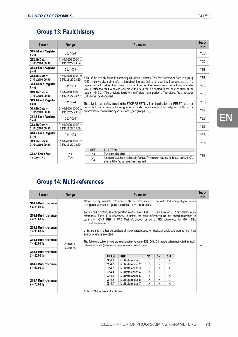
POWER ELECTRONICS SD750
DESCRIPTION OF PROGRAMMING PARAMETERS 71
EN
Group 13: Fault history
Screen Range Function Set on
run
G13.1-Fault Register 1 = 0
0 to 1024
A list of the last six faults in chronological order is shown. The first parameter from this group (G13.1) allows visualizing information about the last fault and, also, it will be used as the first register of fault history. Each time that a fault occurs, the drive shows the fault in parameter G13.1. After the fault is solved and reset, this fault will be shifted to the next position of the register (G13.2). The previous faults will shift down one position. The oldest fault message (G13.6) will be discarded. The drive is rearmed by pressing the STOP-RESET key from the display, the RESET button on the control cabinet door or by using an external display if it exists. The configured faults can be automatically rearmed using Auto Reset (see group G12).
YES
G13.1b-Date = 01/01/2000 00:00
01/01/2000 00:00 to 31/12/2127 23:59
YES
G13.2-Fault Register 2 = 0
0 to 1024 YES
G13.2b-Date = 01/01/2000 00:00
01/01/2000 00:00 to 31/12/2127 23:59
YES
G13.3-Fault Register 3 = 0
0 to 1024 YES
G13.3b-Date = 01/01/2000 00:00
01/01/2000 00:00 to 31/12/2127 23:59
YES
G13.4-Fault Register 4 = 0
0 to 1024 YES
G13.4b-Date = 01/01/2000 00:00
01/01/2000 00:00 to 31/12/2127 23:59
YES
G13.5-Fault Register 5 = 0
0 to 1024 YES
G13.5b-Date = 01/01/2000 00:00
01/01/2000 00:00 to 31/12/2127 23:59
YES
G13.6-Fault Register 6 = 0
0 to 1024 YES
G13.6b-Date = 01/01/2000 00:00
01/01/2000 00:00 to 31/12/2127 23:59
YES
G13.7-Erase fault history = No
No Yes
OPT. FUNCTION
No Function disabled.
Yes It erases fault history (last six faults). The screen returns to default value ‘NO’, after all the faults have been erased.
YES
Group 14: Multi-references
Screen Range Function Set on
run
G14.1-Multi reference 1 = 10.00 %
-250.00 to 250.00%
Allows setting multiple references. These references will be activated using digital inputs configured as multiple speed references or PID references. To use this function, select operating mode, ‘G4.1.4 DIGIT I MODE=2 or 3’ (2 or 3-wires multi-reference). Then, it is necessary to select the multi-references as the speed reference in parameter ‘G3.1 REF 1 SPD=Multireferences’ or as a PID references in ‘G6.1 SEL REF=Multireferences’. Units are set in either percentage of motor rated speed or feedback analogue input range (if an analogue unit is selected). The following table shows the relationship between DI3, DI4, DI5 inputs when activated in multi-reference mode (as a percentage of motor rated speed):
PARM REF DI3 DI4 DI5
G14.1 Multireferences 1 0 0 X
G14.2 Multireferences 2 0 X 0
G14.3 Multireferences 3 0 X X
G14.4 Multireferences 4 X 0 0
G14.5 Multireferences 5 X 0 X
G14.6 Multireferences 6 X X 0
G14.7 Multireferences 7 X X X
Note: 0: Not active and X: Active.
YES
G14.2-Multi reference 2 = 20.00 %
G14.3-Multi reference 3 = 30.00 %
G14.4-Multi reference 4 = 40.00 %
G14.5-Multi reference 5 = 50.00 %
G14.6-Multi reference 6 = 60.00 %
G14.7-Multi reference 7 = 70.00 %
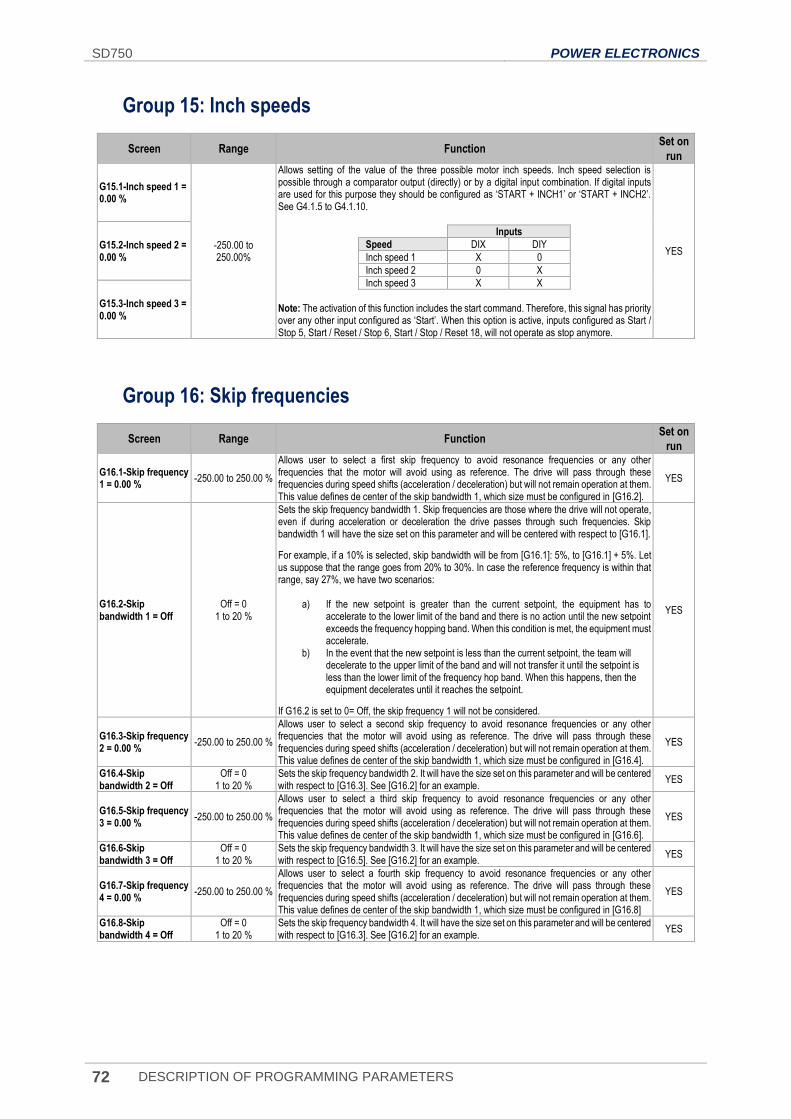
SD750 POWER ELECTRONICS
72 DESCRIPTION OF PROGRAMMING PARAMETERS
Group 15: Inch speeds
Screen Range Function Set on
run
G15.1-Inch speed 1 = 0.00 %
-250.00 to 250.00%
Allows setting of the value of the three possible motor inch speeds. Inch speed selection is possible through a comparator output (directly) or by a digital input combination. If digital inputs are used for this purpose they should be configured as ‘START + INCH1’ or ‘START + INCH2’. See G4.1.5 to G4.1.10.
Inputs
Speed DIX DIY
Inch speed 1 X 0
Inch speed 2 0 X
Inch speed 3 X X
Note: The activation of this function includes the start command. Therefore, this signal has priority over any other input configured as ‘Start’. When this option is active, inputs configured as Start / Stop 5, Start / Reset / Stop 6, Start / Stop / Reset 18, will not operate as stop anymore.
YES G15.2-Inch speed 2 = 0.00 %
G15.3-Inch speed 3 = 0.00 %
Group 16: Skip frequencies
Screen Range Function Set on
run
G16.1-Skip frequency 1 = 0.00 %
-250.00 to 250.00 %
Allows user to select a first skip frequency to avoid resonance frequencies or any other frequencies that the motor will avoid using as reference. The drive will pass through these frequencies during speed shifts (acceleration / deceleration) but will not remain operation at them. This value defines de center of the skip bandwidth 1, which size must be configured in [G16.2].
YES
G16.2-Skip bandwidth 1 = Off
Off = 0 1 to 20 %
Sets the skip frequency bandwidth 1. Skip frequencies are those where the drive will not operate, even if during acceleration or deceleration the drive passes through such frequencies. Skip bandwidth 1 will have the size set on this parameter and will be centered with respect to [G16.1].
For example, if a 10% is selected, skip bandwidth will be from [G16.1]: 5%, to [G16.1] + 5%. Let us suppose that the range goes from 20% to 30%. In case the reference frequency is within that range, say 27%, we have two scenarios:
a) If the new setpoint is greater than the current setpoint, the equipment has to accelerate to the lower limit of the band and there is no action until the new setpoint exceeds the frequency hopping band. When this condition is met, the equipment must accelerate.
b) In the event that the new setpoint is less than the current setpoint, the team will decelerate to the upper limit of the band and will not transfer it until the setpoint is less than the lower limit of the frequency hop band. When this happens, then the equipment decelerates until it reaches the setpoint.
If G16.2 is set to 0= Off, the skip frequency 1 will not be considered.
YES
G16.3-Skip frequency 2 = 0.00 %
-250.00 to 250.00 %
Allows user to select a second skip frequency to avoid resonance frequencies or any other frequencies that the motor will avoid using as reference. The drive will pass through these frequencies during speed shifts (acceleration / deceleration) but will not remain operation at them. This value defines de center of the skip bandwidth 1, which size must be configured in [G16.4].
YES
G16.4-Skip bandwidth 2 = Off
Off = 0 1 to 20 %
Sets the skip frequency bandwidth 2. It will have the size set on this parameter and will be centered with respect to [G16.3]. See [G16.2] for an example.
YES
G16.5-Skip frequency 3 = 0.00 %
-250.00 to 250.00 %
Allows user to select a third skip frequency to avoid resonance frequencies or any other frequencies that the motor will avoid using as reference. The drive will pass through these frequencies during speed shifts (acceleration / deceleration) but will not remain operation at them. This value defines de center of the skip bandwidth 1, which size must be configured in [G16.6].
YES
G16.6-Skip bandwidth 3 = Off
Off = 0 1 to 20 %
Sets the skip frequency bandwidth 3. It will have the size set on this parameter and will be centered with respect to [G16.5]. See [G16.2] for an example.
YES
G16.7-Skip frequency 4 = 0.00 %
-250.00 to 250.00 %
Allows user to select a fourth skip frequency to avoid resonance frequencies or any other frequencies that the motor will avoid using as reference. The drive will pass through these frequencies during speed shifts (acceleration / deceleration) but will not remain operation at them. This value defines de center of the skip bandwidth 1, which size must be configured in [G16.8]
YES
G16.8-Skip bandwidth 4 = Off
Off = 0 1 to 20 %
Sets the skip frequency bandwidth 4. It will have the size set on this parameter and will be centered with respect to [G16.3]. See [G16.2] for an example.
YES
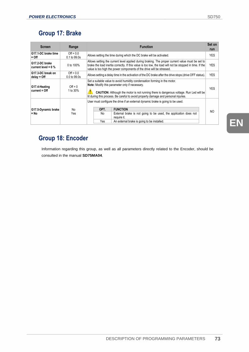
POWER ELECTRONICS SD750
DESCRIPTION OF PROGRAMMING PARAMETERS 73
EN
Group 17: Brake
Screen Range Function Set on
run G17.1-DC brake time = Off
Off = 0.0 0.1 to 99.0s
Allows setting the time during which the DC brake will be activated. YES
G17.2-DC brake current level = 0 %
0 to 100% Allows setting the current level applied during braking. The proper current value must be set to brake the load inertia correctly. If this value is too low, the load will not be stopped in time. If the value is too high the power components of the drive will be stressed.
YES
G17.3-DC break on delay = Off
Off = 0.0 0.0 to 99.0s
Allows setting a delay time in the activation of the DC brake after the drive stops (drive OFF status). YES
G17.4-Heating current = Off
Off = 0 1 to 30%
Set a suitable value to avoid humidity condensation forming in the motor. Note: Modify this parameter only if necessary. CAUTION: Although the motor is not running there is dangerous voltage. Run Led will be lit during this process. Be careful to avoid property damage and personal injuries.
YES
G17.5-Dynamic brake = No
No Yes
User must configure the drive if an external dynamic brake is going to be used.
OPT. FUNCTION
No External brake is not going to be used, the application does not require it.
Yes An external brake is going to be installed.
NO
Group 18: Encoder
Information regarding this group, as well as all parameters directly related to the Encoder, should be
consulted in the manual SD75MA04.
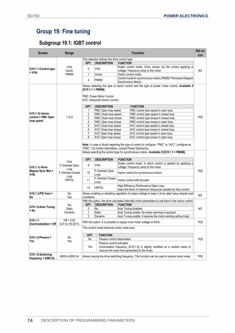
SD750 POWER ELECTRONICS
74 DESCRIPTION OF PROGRAMMING PARAMETERS
Group 19: Fine tuning
Subgroup 19.1: IGBT control
Screen Range Function Set on
run
G19.1.1-Control type = V/Hz
V/Hz Vector PMSM
This selection defines the drive control type.
OPT. DESCRIPTION FUNCTION
0 V/Hz Scalar control mode. Drive carries out the control applying a voltage / frequency ramp to the motor.
1 Vector Vector control mode.
2 PMSM Control mode for synchronous motors (PMSM: Permanent Magnet Synchronous Motor).
NO
G19.1.1b-Vector control = PMC Open loop speed
1 to 8
Allows selecting the type of vector control and the type of power motor control. Available if [G19.1.1 = PMSM].
PMC: Power Motor Control AVC: Advanced Vector Control.
OPT. DESCRIPTION FUNCTION
1 PMC Open loop speed PMC control type speed in open loop.
2 PMC Close loop speed PMC control type speed in closed loop.
3 PMC Close loop torque PMC control type torque in closed loop.
4 PMC Open loop torque PMC control type torque in open loop.
5 AVC Close loop speed AVC control type speed in closed loop.
6 AVC Close loop torque AVC control type torque in closed loop.
7 AVC Open loop speed AVC control type speed in open loop.
8 AVC Open loop torque AVC control type torque in open loop.
Note: In case of doubt regarding the type of control to configure, “PMC” or “AVC”, configure as “PMC”. For further information, consult Power Electronics.
YES
G19.1.1c-Perm Magnet Sync Mot = V/Hz
V/Hz F.Oriented Open
Loop F.Oriented Closed
Loop HEPOL
Allows selecting the control type for synchronous motors. Available if [G19.1.1 = PMSM].
OPT. DESCRIPTION FUNCTION
9 V/Hz Scalar control mode, in which control is applied by applying a voltage / frequency ramp to the motor.
10 F.Oriented Open Loop
Vector control for synchronous motors.
11 F.Oriented Closed Loop
Vector control with encoder.
12 HEPOL High Efficiency Performance Open Loop. Uses the block of maximum torque per ampere for flow control.
YES
G19.1.3-PID Vout = No
No Yes
Allows enabling or disabling regulation of output voltage to keep it at its rated value despite load conditions.
NO
G19.1.6-Auto Tuning = No
No Static
Dynamic
With this option, the drive calculates internally motor parameters to use them in the vector control.
OPT. DESCRIPTION FUNCTION
0 No Auto Tuning disabled.
1 Static Auto Tuning enable. No motor spinning is required.
2 Dynamic Auto Tuning enable. It requires the motor working without load.
NO
G19.1.7-Overmodulation = Off
Off = 0.00 0.01 to 100.00 %
With this option, it is possible to supply more motor voltage at 50Hz. YES
G19.1.8-Pewave = Yes
No Yes
This control mode improves motor noise tone.
OPT. FUNCTION
No Pewave control deactivated.
Yes Pewave control activated. Commutation frequency (G19.1.9) is slightly modified on a random basis to improve the noise tone generated by the motor.
YES
G19.1.9-Switching frequency = 4000 Hz
4000 to 8000 Hz Allows varying the drive switching frequency. This function can be used to reduce motor noise. YES
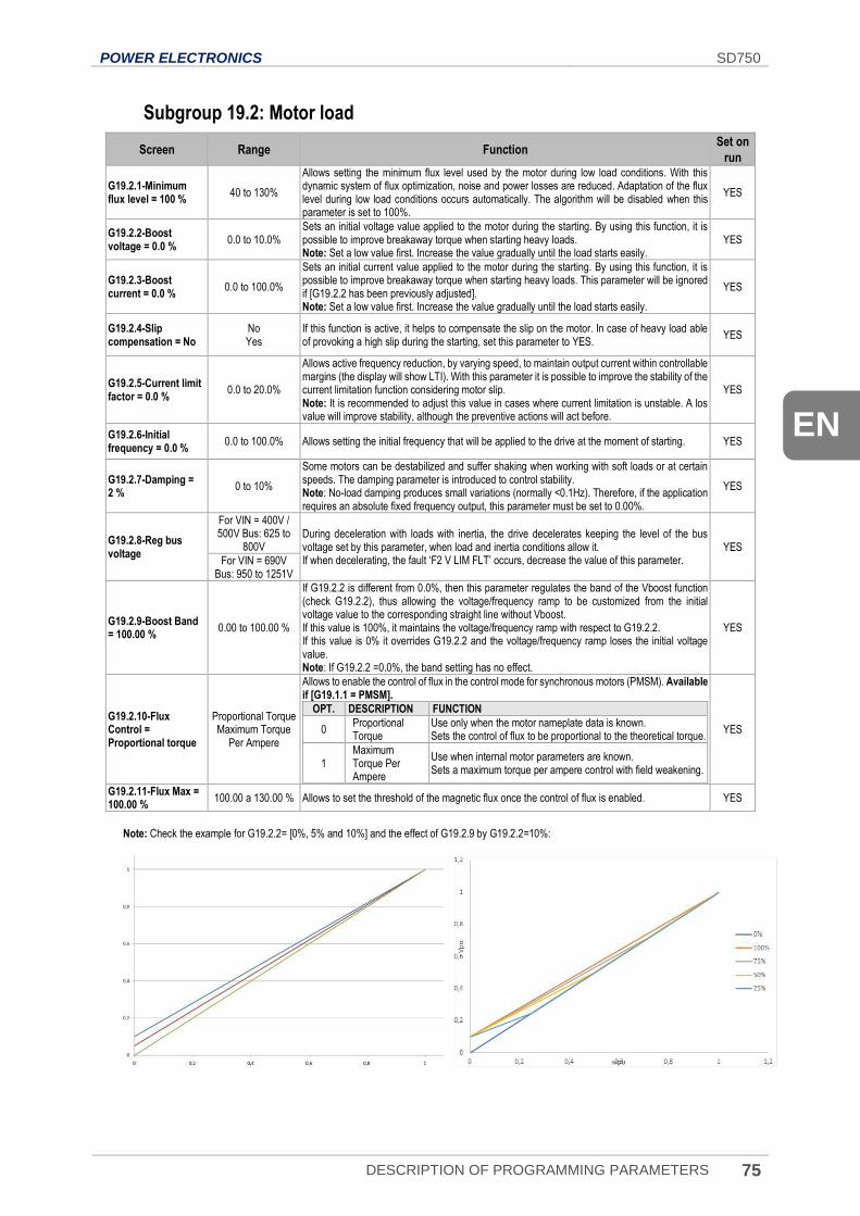
POWER ELECTRONICS SD750
DESCRIPTION OF PROGRAMMING PARAMETERS 75
EN
Subgroup 19.2: Motor load
Screen Range Function Set on
run
G19.2.1-Minimum flux level = 100 %
40 to 130%
Allows setting the minimum flux level used by the motor during low load conditions. With this dynamic system of flux optimization, noise and power losses are reduced. Adaptation of the flux level during low load conditions occurs automatically. The algorithm will be disabled when this parameter is set to 100%.
YES
G19.2.2-Boost voltage = 0.0 %
0.0 to 10.0% Sets an initial voltage value applied to the motor during the starting. By using this function, it is possible to improve breakaway torque when starting heavy loads. Note: Set a low value first. Increase the value gradually until the load starts easily.
YES
G19.2.3-Boost current = 0.0 %
0.0 to 100.0%
Sets an initial current value applied to the motor during the starting. By using this function, it is possible to improve breakaway torque when starting heavy loads. This parameter will be ignored if [G19.2.2 has been previously adjusted]. Note: Set a low value first. Increase the value gradually until the load starts easily.
YES
G19.2.4-Slip compensation = No
No Yes
If this function is active, it helps to compensate the slip on the motor. In case of heavy load able of provoking a high slip during the starting, set this parameter to YES.
YES
G19.2.5-Current limit factor = 0.0 %
0.0 to 20.0%
Allows active frequency reduction, by varying speed, to maintain output current within controllable margins (the display will show LTI). With this parameter it is possible to improve the stability of the current limitation function considering motor slip. Note: It is recommended to adjust this value in cases where current limitation is unstable. A los value will improve stability, although the preventive actions will act before.
YES
G19.2.6-Initial frequency = 0.0 %
0.0 to 100.0% Allows setting the initial frequency that will be applied to the drive at the moment of starting. YES
G19.2.7-Damping = 2 %
0 to 10%
Some motors can be destabilized and suffer shaking when working with soft loads or at certain speeds. The damping parameter is introduced to control stability. Note: No-load damping produces small variations (normally <0.1Hz). Therefore, if the application requires an absolute fixed frequency output, this parameter must be set to 0.00%.
YES
G19.2.8-Reg bus voltage
For VIN = 400V / 500V Bus: 625 to
800V During deceleration with loads with inertia, the drive decelerates keeping the level of the bus voltage set by this parameter, when load and inertia conditions allow it. If when decelerating, the fault ‘F2 V LIM FLT’ occurs, decrease the value of this parameter.
YES For VIN = 690V
Bus: 950 to 1251V
G19.2.9-Boost Band = 100.00 %
0.00 to 100.00 %
If G19.2.2 is different from 0.0%, then this parameter regulates the band of the Vboost function (check G19.2.2), thus allowing the voltage/frequency ramp to be customized from the initial voltage value to the corresponding straight line without Vboost. If this value is 100%, it maintains the voltage/frequency ramp with respect to G19.2.2. If this value is 0% it overrides G19.2.2 and the voltage/frequency ramp loses the initial voltage value. Note: If G19.2.2 =0.0%, the band setting has no effect.
YES
G19.2.10-Flux Control = Proportional torque
Proportional Torque Maximum Torque
Per Ampere
Allows to enable the control of flux in the control mode for synchronous motors (PMSM). Available if [G19.1.1 = PMSM].
OPT. DESCRIPTION FUNCTION
0 Proportional Torque
Use only when the motor nameplate data is known. Sets the control of flux to be proportional to the theoretical torque.
1 Maximum Torque Per Ampere
Use when internal motor parameters are known. Sets a maximum torque per ampere control with field weakening.
YES
G19.2.11-Flux Max = 100.00 %
100.00 a 130.00 % Allows to set the threshold of the magnetic flux once the control of flux is enabled. YES
Note: Check the example for G19.2.2= [0%, 5% and 10%] and the effect of G19.2.9 by G19.2.2=10%:
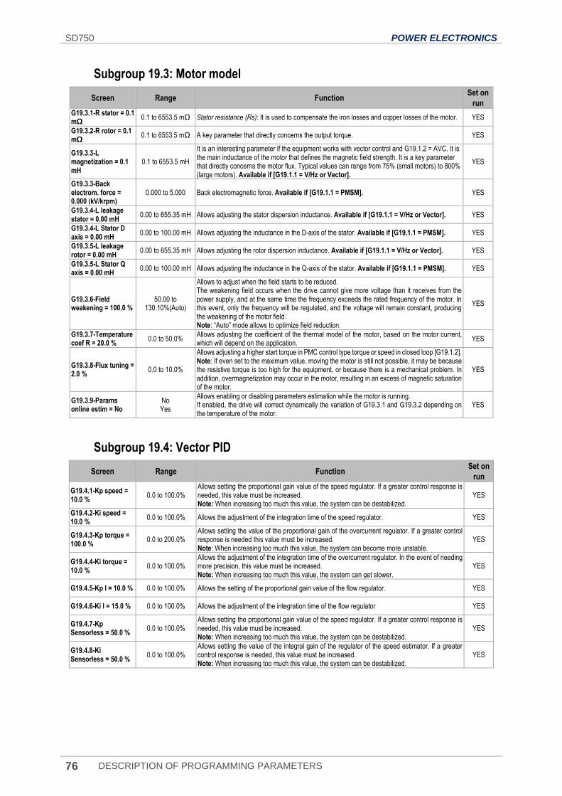
SD750 POWER ELECTRONICS
76 DESCRIPTION OF PROGRAMMING PARAMETERS
Subgroup 19.3: Motor model
Screen Range Function Set on
run G19.3.1-R stator = 0.1 mΩ
0.1 to 6553.5 mΩ Stator resistance (Rs): It is used to compensate the iron losses and copper losses of the motor. YES
G19.3.2-R rotor = 0.1 mΩ
0.1 to 6553.5 mΩ A key parameter that directly concerns the output torque. YES
G19.3.3-L magnetization = 0.1 mH
0.1 to 6553.5 mH
It is an interesting parameter if the equipment works with vector control and G19.1.2 = AVC. It is the main inductance of the motor that defines the magnetic field strength. It is a key parameter that directly concerns the motor flux. Typical values can range from 75% (small motors) to 800% (large motors). Available if [G19.1.1 = V/Hz or Vector].
YES
G19.3.3-Back electrom. force = 0.000 (kV/krpm)
0.000 to 5.000 Back electromagnetic force. Available if [G19.1.1 = PMSM]. YES
G19.3.4-L leakage stator = 0.00 mH
0.00 to 655.35 mH Allows adjusting the stator dispersion inductance. Available if [G19.1.1 = V/Hz or Vector]. YES
G19.3.4-L Stator D axis = 0.00 mH
0.00 to 100.00 mH Allows adjusting the inductance in the D-axis of the stator. Available if [G19.1.1 = PMSM]. YES
G19.3.5-L leakage rotor = 0.00 mH
0.00 to 655.35 mH Allows adjusting the rotor dispersion inductance. Available if [G19.1.1 = V/Hz or Vector]. YES
G19.3.5-L Stator Q axis = 0.00 mH
0.00 to 100.00 mH Allows adjusting the inductance in the Q-axis of the stator. Available if [G19.1.1 = PMSM]. YES
G19.3.6-Field weakening = 100.0 %
50.00 to 130.10%(Auto)
Allows to adjust when the field starts to be reduced. The weakening field occurs when the drive cannot give more voltage than it receives from the power supply, and at the same time the frequency exceeds the rated frequency of the motor. In this event, only the frequency will be regulated, and the voltage will remain constant, producing the weakening of the motor field. Note: “Auto” mode allows to optimize field reduction.
YES
G19.3.7-Temperature coef R = 20.0 %
0.0 to 50.0% Allows adjusting the coefficient of the thermal model of the motor, based on the motor current, which will depend on the application.
YES
G19.3.8-Flux tuning = 2.0 %
0.0 to 10.0%
Allows adjusting a higher start torque in PMC control type torque or speed in closed loop [G19.1.2]. Note: If even set to the maximum value, moving the motor is still not possible, it may be because the resistive torque is too high for the equipment, or because there is a mechanical problem. In addition, overmagnetization may occur in the motor, resulting in an excess of magnetic saturation of the motor.
YES
G19.3.9-Params online estim = No
No Yes
Allows enabling or disabling parameters estimation while the motor is running. If enabled, the drive will correct dynamically the variation of G19.3.1 and G19.3.2 depending on the temperature of the motor.
YES
Subgroup 19.4: Vector PID
Screen Range Function Set on
run
G19.4.1-Kp speed = 10.0 %
0.0 to 100.0% Allows setting the proportional gain value of the speed regulator. If a greater control response is needed, this value must be increased. Note: When increasing too much this value, the system can be destabilized.
YES
G19.4.2-Ki speed = 10.0 %
0.0 to 100.0% Allows the adjustment of the integration time of the speed regulator. YES
G19.4.3-Kp torque = 100.0 %
0.0 to 200.0% Allows setting the value of the proportional gain of the overcurrent regulator. If a greater control response is needed this value must be increased. Note: When increasing too much this value, the system can become more unstable.
YES
G19.4.4-Ki torque = 10.0 %
0.0 to 100.0% Allows the adjustment of the integration time of the overcurrent regulator. In the event of needing more precision, this value must be increased. Note: When increasing too much this value, the system can get slower.
YES
G19.4.5-Kp I = 10.0 % 0.0 to 100.0% Allows the setting of the proportional gain value of the flow regulator. YES
G19.4.6-Ki I = 15.0 % 0.0 to 100.0% Allows the adjustment of the integration time of the flow regulator YES
G19.4.7-Kp Sensorless = 50.0 %
0.0 to 100.0% Allows setting the proportional gain value of the speed regulator. If a greater control response is needed, this value must be increased. Note: When increasing too much this value, the system can be destabilized.
YES
G19.4.8-Ki Sensorless = 50.0 %
0.0 to 100.0% Allows setting the value of the integral gain of the regulator of the speed estimator. If a greater control response is needed, this value must be increased. Note: When increasing too much this value, the system can be destabilized.
YES
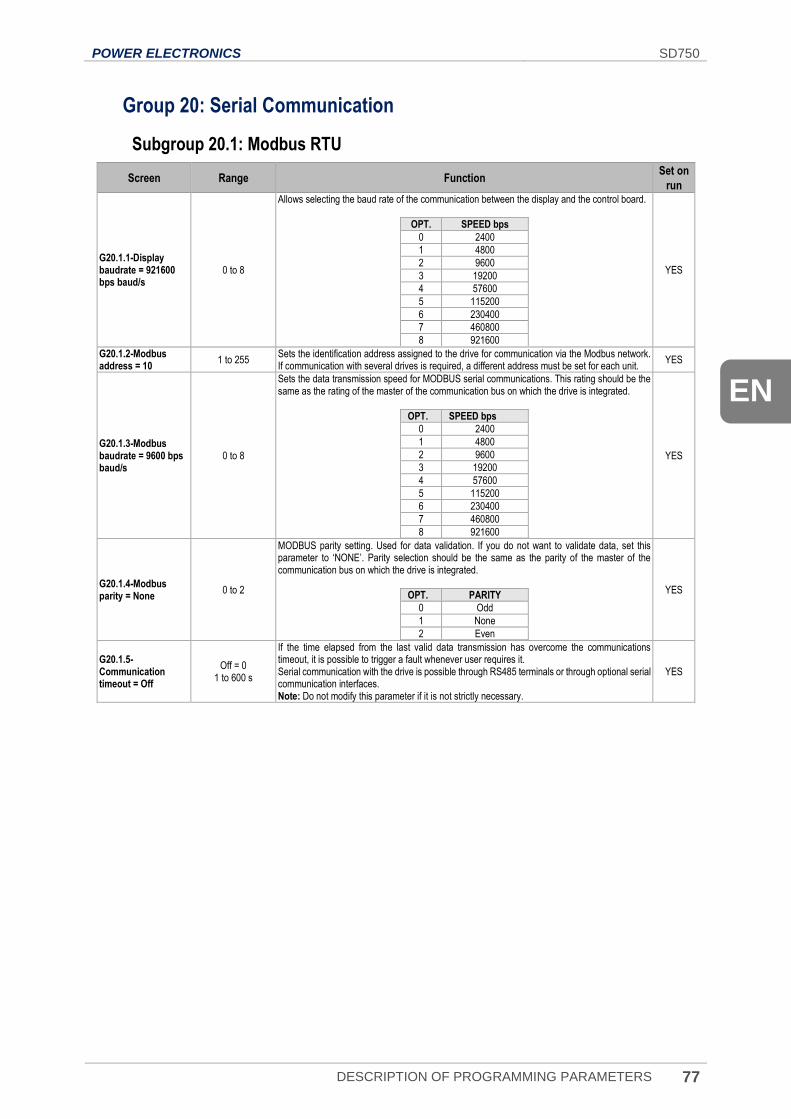
POWER ELECTRONICS SD750
DESCRIPTION OF PROGRAMMING PARAMETERS 77
EN
Group 20: Serial Communication
Subgroup 20.1: Modbus RTU
Screen Range Function Set on
run
G20.1.1-Display baudrate = 921600 bps baud/s
0 to 8
Allows selecting the baud rate of the communication between the display and the control board.
OPT. SPEED bps
0 2400
1 4800
2 9600
3 19200
4 57600
5 115200
6 230400
7 460800
8 921600
YES
G20.1.2-Modbus address = 10
1 to 255 Sets the identification address assigned to the drive for communication via the Modbus network. If communication with several drives is required, a different address must be set for each unit.
YES
G20.1.3-Modbus baudrate = 9600 bps baud/s
0 to 8
Sets the data transmission speed for MODBUS serial communications. This rating should be the same as the rating of the master of the communication bus on which the drive is integrated.
OPT. SPEED bps
0 2400
1 4800
2 9600
3 19200
4 57600
5 115200
6 230400
7 460800
8 921600
YES
G20.1.4-Modbus parity = None
0 to 2
MODBUS parity setting. Used for data validation. If you do not want to validate data, set this parameter to ‘NONE’. Parity selection should be the same as the parity of the master of the communication bus on which the drive is integrated.
OPT. PARITY
0 Odd
1 None
2 Even
YES
G20.1.5-Communication timeout = Off
Off = 0 1 to 600 s
If the time elapsed from the last valid data transmission has overcome the communications timeout, it is possible to trigger a fault whenever user requires it. Serial communication with the drive is possible through RS485 terminals or through optional serial communication interfaces. Note: Do not modify this parameter if it is not strictly necessary.
YES
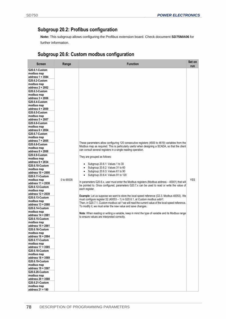
SD750 POWER ELECTRONICS
78 DESCRIPTION OF PROGRAMMING PARAMETERS
Subgroup 20.2: Profibus configuration
Note: This subgroup allows configuring the Profibus extension board. Check document SD75MA06 for
further information.
Subgroup 20.6: Custom modbus configuration
Screen Range Function Set on
run G20.6.1-Custom modbus map address 1 = 3584
0 to 65535
These parameters allow configuring 120 consecutive registers (4500 to 4619) variables from the Modbus map as required. This is particularly useful when designing a SCADA, so that the client can consult several registers in a single reading operation. They are grouped as follows:
• Subgroup 20.6.1: Values 1 to 30
• Subgroup 20.6.2: Values 31 to 60
• Subgroup 20.6.3: Values 61 to 90
• Subgroup 20.6.4: Values 91 to 120 In parameters G20.6.x, user must enter the Modbus registers (Modbus address – 40001) that will be pointed to. Once configured, parameters G20.7.x can be used to read or write the value of each register. Example: Let us suppose we want to store the local speed reference (G3.3, Modbus 40053). We must configure register 52 (40053 – 1) in G20.6.1, at Custom modbus addr1. Then, in G20.7.1, Custom modbus val 1 we will read the current value of the local speed reference. To modify it, we must enter the new value and save changes. Note: When reading or writing a variable, keep in mind the type of variable and its Modbus range to ensure values are interpreted correctly.
YES
G20.6.2-Custom modbus map address 2 = 2002
G20.6.3-Custom modbus map address 3 = 2006
G20.6.4-Custom modbus map address 4 = 2009
G20.6.5-Custom modbus map address 5 = 2007
G20.6.6-Custom modbus map address 6 = 2004
G20.6.7-Custom modbus map address 7 = 2005
G20.6.8-Custom modbus map address 8 = 2008
G20.6.9-Custom modbus map address 9 = 2034
G20.6.10-Custom modbus map address 10 = 2000
G20.6.11-Custom modbus map address 11 = 2038
G20.6.12-Custom modbus map address 12 = 2039
G20.6.13-Custom modbus map address 13 = 2080
G20.6.14-Custom modbus map address 14 = 2081
G20.6.15-Custom modbus map address 15 = 2061
G20.6.16-Custom modbus map address 16 = 2064
G20.6.17-Custom modbus map address 17 = 3585
G20.6.18-Custom modbus map address 18 = 3569
G20.6.19-Custom modbus map address 19 = 3587
G20.6.20-Custom modbus map address 20 = 3588
G20.6.21-Custom modbus map address 21 = 180
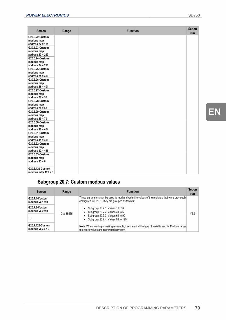
POWER ELECTRONICS SD750
DESCRIPTION OF PROGRAMMING PARAMETERS 79
EN
Screen Range Function Set on
run G20.6.22-Custom modbus map address 22 = 181
G20.6.23-Custom modbus map address 23 = 223
G20.6.24-Custom modbus map address 24 = 220
G20.6.25-Custom modbus map address 25 = 400
G20.6.26-Custom modbus map address 26 = 401
G20.6.27-Custom modbus map address 27 = 50
G20.6.28-Custom modbus map address 28 = 53
G20.6.29-Custom modbus map address 29 = 70
G20.6.30-Custom modbus map address 30 = 404
G20.6.31-Custom modbus map address 31 = 408
G20.6.32-Custom modbus map address 32 = 416
G20.6.33-Custom modbus map address 33 = 0
…
G20.6.120-Custom modbus addr 120 = 0
Subgroup 20.7: Custom modbus values
Screen Range Function Set on
run
G20.7.1-Custom modbus val1 = 0
0 to 65535
These parameters can be used to read and write the values of the registers that were previously configured in G20.6. They are grouped as follows:
• Subgroup 20.7.1: Values 1 to 30
• Subgroup 20.7.2: Values 31 to 60
• Subgroup 20.7.3: Values 61 to 90
• Subgroup 20.7.4: Values 91 to 120 Note: When reading or writing a variable, keep in mind the type of variable and its Modbus range to ensure values are interpreted correctly.
YES
G20.7.2-Custom modbus val2 = 0
…
G20.7.120-Custom modbus val30 = 0
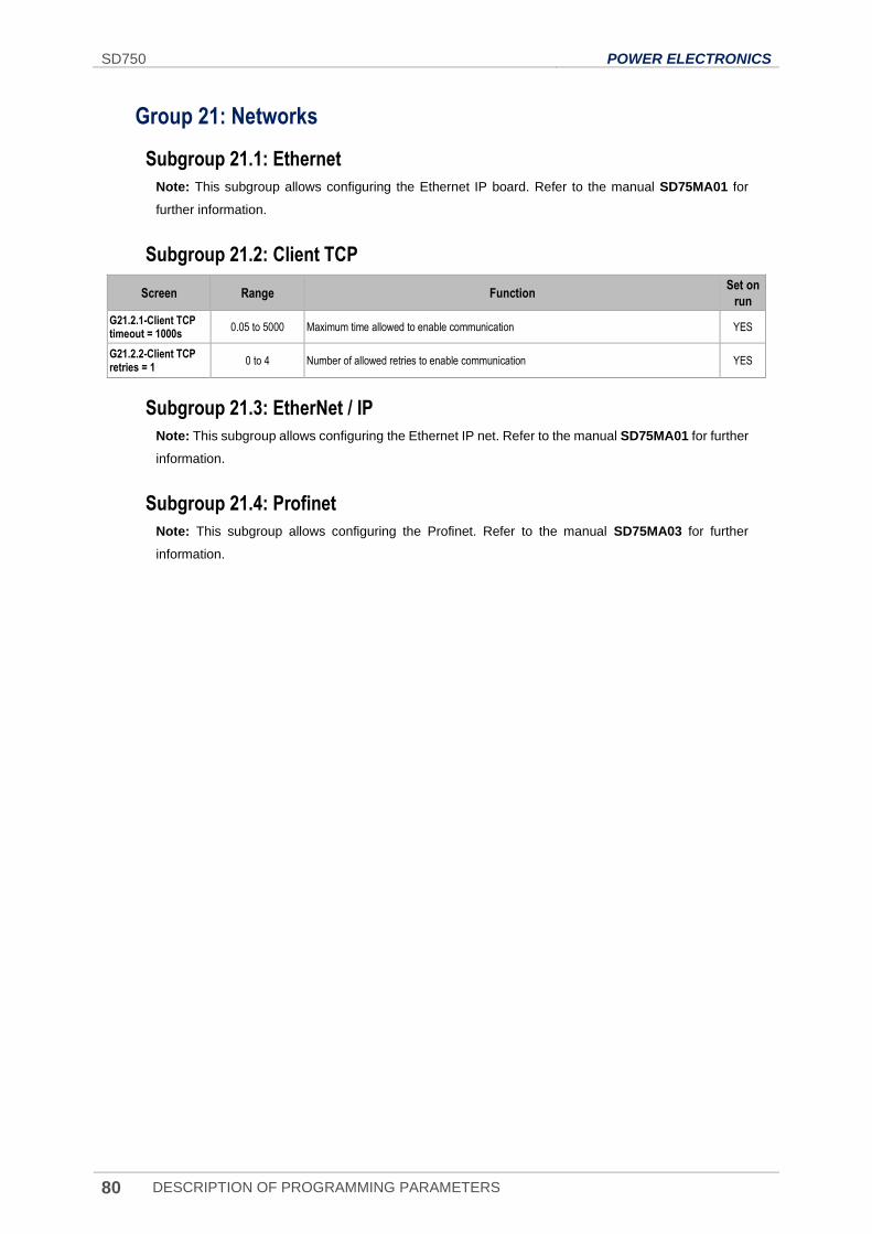
SD750 POWER ELECTRONICS
80 DESCRIPTION OF PROGRAMMING PARAMETERS
Group 21: Networks
Subgroup 21.1: Ethernet
Note: This subgroup allows configuring the Ethernet IP board. Refer to the manual SD75MA01 for
further information.
Subgroup 21.2: Client TCP
Screen Range Function Set on
run
G21.2.1-Client TCP timeout = 1000s
0.05 to 5000 Maximum time allowed to enable communication YES
G21.2.2-Client TCP retries = 1
0 to 4 Number of allowed retries to enable communication YES
Subgroup 21.3: EtherNet / IP
Note: This subgroup allows configuring the Ethernet IP net. Refer to the manual SD75MA01 for further
information.
Subgroup 21.4: Profinet
Note: This subgroup allows configuring the Profinet. Refer to the manual SD75MA03 for further
information.
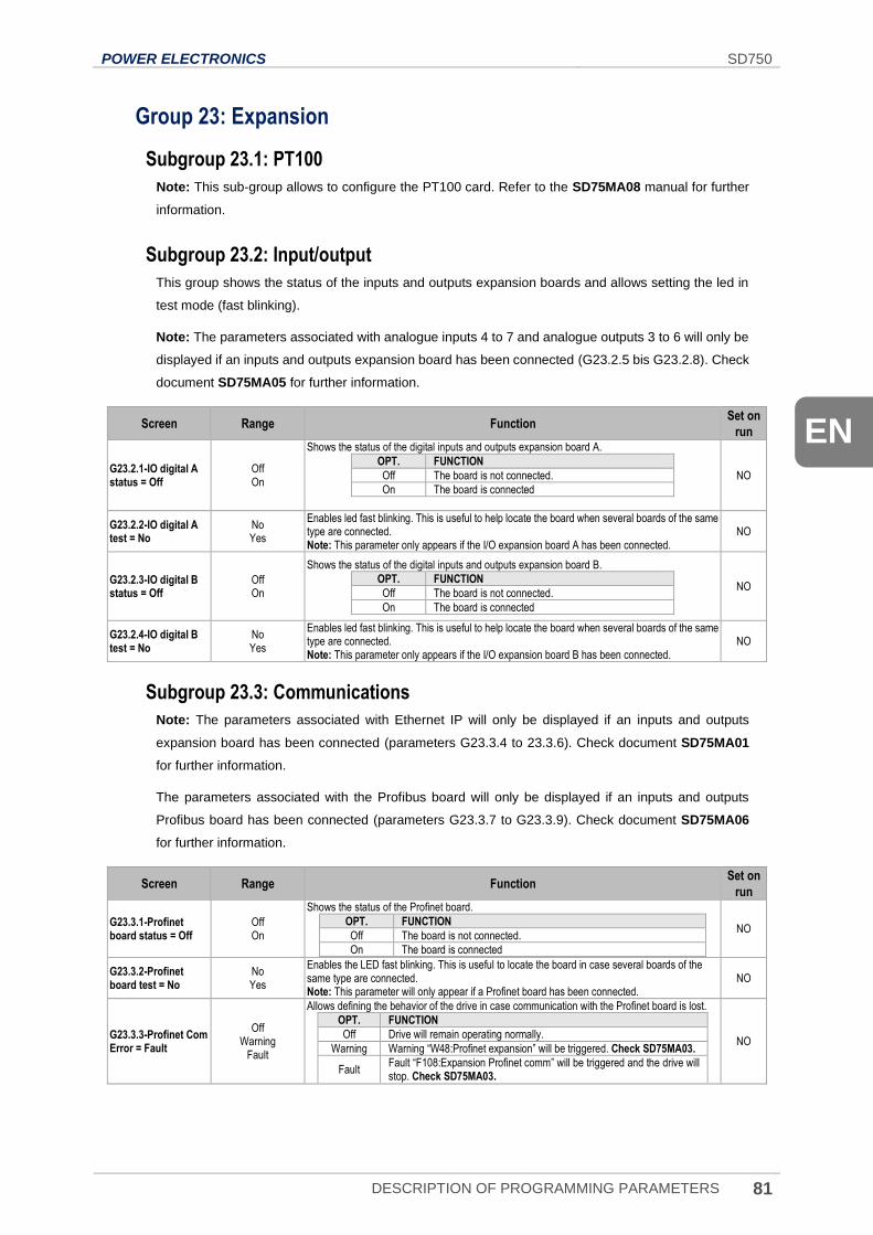
POWER ELECTRONICS SD750
DESCRIPTION OF PROGRAMMING PARAMETERS 81
EN
Group 23: Expansion
Subgroup 23.1: PT100
Note: This sub-group allows to configure the PT100 card. Refer to the SD75MA08 manual for further
information.
Subgroup 23.2: Input/output
This group shows the status of the inputs and outputs expansion boards and allows setting the led in
test mode (fast blinking).
Note: The parameters associated with analogue inputs 4 to 7 and analogue outputs 3 to 6 will only be
displayed if an inputs and outputs expansion board has been connected (G23.2.5 bis G23.2.8). Check
document SD75MA05 for further information.
Screen Range Function Set on
run
G23.2.1-IO digital A status = Off
Off On
Shows the status of the digital inputs and outputs expansion board A.
OPT. FUNCTION
Off The board is not connected.
On The board is connected
NO
G23.2.2-IO digital A test = No
No Yes
Enables led fast blinking. This is useful to help locate the board when several boards of the same type are connected. Note: This parameter only appears if the I/O expansion board A has been connected.
NO
G23.2.3-IO digital B status = Off
Off On
Shows the status of the digital inputs and outputs expansion board B.
OPT. FUNCTION
Off The board is not connected.
On The board is connected
NO
G23.2.4-IO digital B test = No
No Yes
Enables led fast blinking. This is useful to help locate the board when several boards of the same type are connected. Note: This parameter only appears if the I/O expansion board B has been connected.
NO
Subgroup 23.3: Communications
Note: The parameters associated with Ethernet IP will only be displayed if an inputs and outputs
expansion board has been connected (parameters G23.3.4 to 23.3.6). Check document SD75MA01
for further information.
The parameters associated with the Profibus board will only be displayed if an inputs and outputs
Profibus board has been connected (parameters G23.3.7 to G23.3.9). Check document SD75MA06
for further information.
Screen Range Function Set on
run
G23.3.1-Profinet board status = Off
Off On
Shows the status of the Profinet board.
OPT. FUNCTION
Off The board is not connected.
On The board is connected
NO
G23.3.2-Profinet board test = No
No Yes
Enables the LED fast blinking. This is useful to locate the board in case several boards of the same type are connected. Note: This parameter will only appear if a Profinet board has been connected.
NO
G23.3.3-Profinet Com Error = Fault
Off Warning
Fault
Allows defining the behavior of the drive in case communication with the Profinet board is lost.
OPT. FUNCTION
Off Drive will remain operating normally.
Warning Warning “W48:Profinet expansion” will be triggered. Check SD75MA03.
Fault Fault “F108:Expansion Profinet comm” will be triggered and the drive will stop. Check SD75MA03.
NO
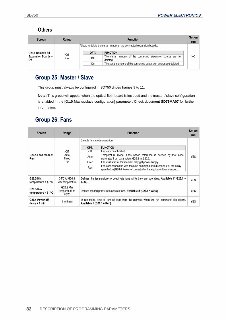
SD750 POWER ELECTRONICS
82 DESCRIPTION OF PROGRAMMING PARAMETERS
Others
Screen Range Function Set on
run
G23.4-Remove All Expansion Boards = Off
Off On
Allows to delete the serial number of the connected expansion boards.
OPT. FUNCTION
Off The serial numbers of the connected expansion boards are not deleted.
On The serial numbers of the connected expansion boards are deleted.
NO
Group 25: Master / Slave
This group must always be configured in SD750 drives frames 9 to 11.
Note: This group will appear when the optical fiber board is included and the master / slave configuration
is enabled in the [G1.9 Master/slave configuration] parameter. Check document SD75MA07 for further
information.
Group 26: Fans
Screen Range Function Set on
run
G26.1-Fans mode = Run
Off Auto Fixed Run
Selects fans mode operation.
OPT. FUNCTION
Off Fans are deactivated.
Auto Temperature mode. Fans speed reference is defined by the slope generated from parameters G26.2 to G26.3.
Fixed Fans will start at the moment they get power supply.
Run Fans are connected with the start command and disconnect at the delay specified in [G26.4 Power off delay] after the equipment has stopped.
YES
G26.2-Min temperature = 47 ºC
35ºC to G26.3 Max temperature
Defines the temperature to deactivate fans while they are operating. Available if [G26.1 = Auto].
YES
G26.3-Max temperature = 51 ºC
G26.2 Min temperature to
80ºC Defines the temperature to activate fans. Available if [G26.1 = Auto]. YES
G26.4-Power off delay = 1 min
1 to 5 min In run mode, time to turn off fans from the moment when the run command disappears. Available if [G26.1 = Run].
YES
POWER ELECTRONICS SD750
MODBUS COMMUNICATION 83
EN
6. MODBUS COMMUNICATION
Supported Modbus Function Codes
Serial communications protocol implemented by SD750 drives adheres to Modbus Industrial standard
communications protocol of Modicon. From all the functions that exist in the Modbus protocol, the drive
uses the Reading and Writing functions:
Function Description Registers Number
3 Registers Reading 120
16 Registers Writing 120
The implementation of these function codes in the drive allows reading up to 120 registers from a
Parameters Group in a single frame. In case of requiring accessing consecutive memory registers, but
which belong to different groups, user will need to use as many frames as groups are involved.
Modbus function code Nº 3: Registers reading
This function code allows the Modbus controller (master) to read the content of the data registers
indicated in the drive (slave). This function code only admits unicast addressing. Broadcast or
groupcast addressing are not possible with this function code.
The implementation of this function code in the drive allows reading up to 120 registers of the drive
with consecutive addresses in a single frame.
Next, a frame is shown where the master attempts to read the content of 3 registers of a drive where
the current used by each phase is. The information that should be attached in the ask frame is the
following:
• Data address of the drive.
• Modbus function code (3 Registers reading).
• Starting Data address.
• Registers number for reading.
• CRC-16 code.
The answer of the drive (slave) should contain the following fields:
• Data address of the slave.
• Modbus function code (3 Registers reading).
• Bytes number for reading.
• Bytes number / 2 registers.
• CRC-16 code.
6
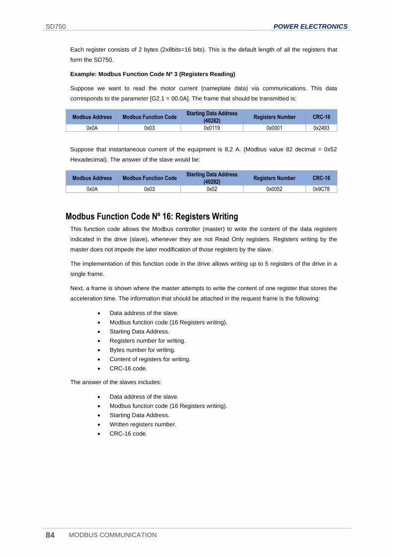
SD750 POWER ELECTRONICS
84 MODBUS COMMUNICATION
Each register consists of 2 bytes (2x8bits=16 bits). This is the default length of all the registers that
form the SD750.
Example: Modbus Function Code Nº 3 (Registers Reading)
Suppose we want to read the motor current (nameplate data) via communications. This data
corresponds to the parameter [G2.1 = 00.0A]. The frame that should be transmitted is:
Modbus Address Modbus Function Code Starting Data Address
(40282) Registers Number CRC-16
0x0A 0x03 0x0119 0x0001 0x2493
Suppose that instantaneous current of the equipment is 8,2 A. (Modbus value 82 decimal = 0x52
Hexadecimal). The answer of the slave would be:
Modbus Address Modbus Function Code Starting Data Address
(40282) Registers Number CRC-16
0x0A 0x03 0x02 0x0052 0x9C78
Modbus Function Code Nº 16: Registers Writing
This function code allows the Modbus controller (master) to write the content of the data registers
indicated in the drive (slave), whenever they are not Read Only registers. Registers writing by the
master does not impede the later modification of those registers by the slave.
The implementation of this function code in the drive allows writing up to 5 registers of the drive in a
single frame.
Next, a frame is shown where the master attempts to write the content of one register that stores the
acceleration time. The information that should be attached in the request frame is the following:
• Data address of the slave.
• Modbus function code (16 Registers writing).
• Starting Data Address.
• Registers number for writing.
• Bytes number for writing.
• Content of registers for writing.
• CRC-16 code.
The answer of the slaves includes:
• Data address of the slave.
• Modbus function code (16 Registers writing).
• Starting Data Address.
• Written registers number.
• CRC-16 code.
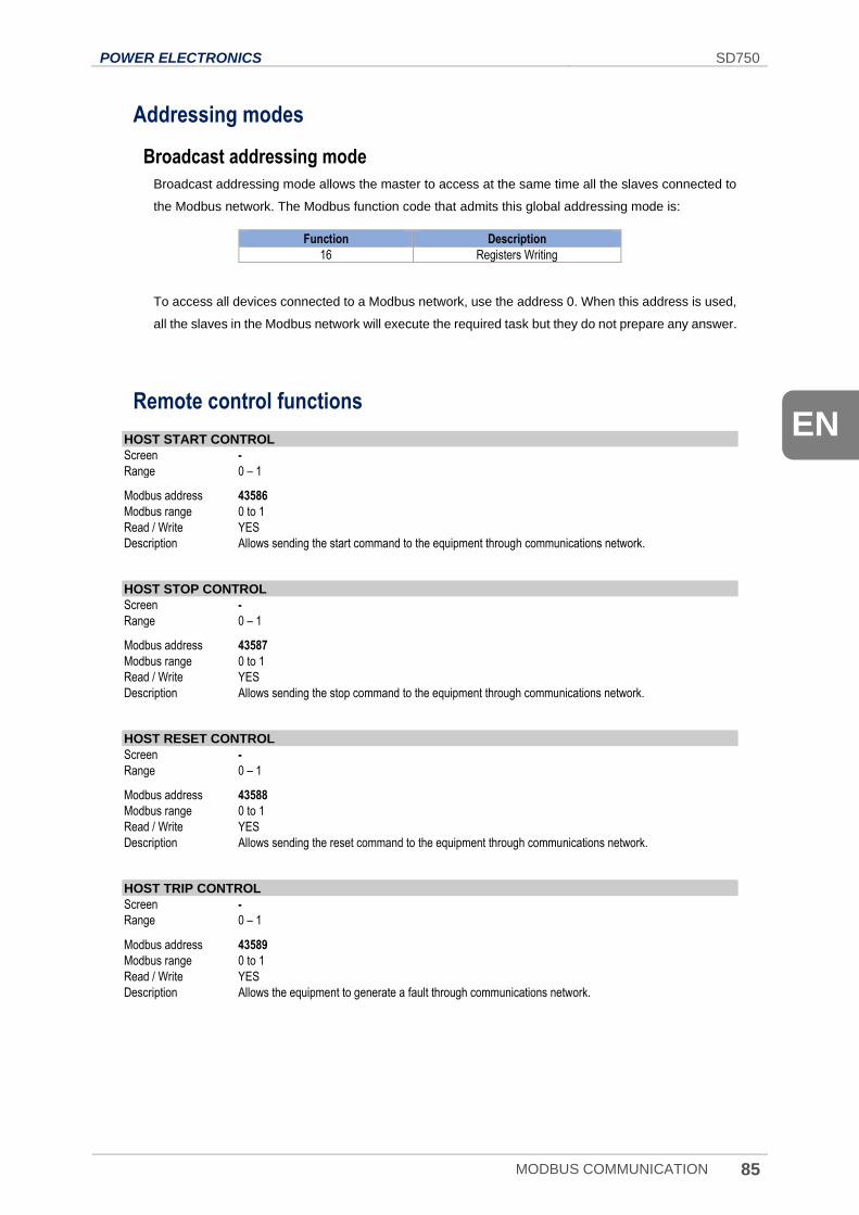
POWER ELECTRONICS SD750
MODBUS COMMUNICATION 85
EN
Addressing modes
Broadcast addressing mode
Broadcast addressing mode allows the master to access at the same time all the slaves connected to
the Modbus network. The Modbus function code that admits this global addressing mode is:
Function Description
16 Registers Writing
To access all devices connected to a Modbus network, use the address 0. When this address is used,
all the slaves in the Modbus network will execute the required task but they do not prepare any answer.
Remote control functions
HOST START CONTROL
Screen -
Range 0 – 1
Modbus address 43586
Modbus range 0 to 1
Read / Write YES
Description Allows sending the start command to the equipment through communications network.
HOST STOP CONTROL
Screen -
Range 0 – 1
Modbus address 43587
Modbus range 0 to 1
Read / Write YES
Description Allows sending the stop command to the equipment through communications network.
HOST RESET CONTROL
Screen -
Range 0 – 1
Modbus address 43588
Modbus range 0 to 1
Read / Write YES
Description Allows sending the reset command to the equipment through communications network.
HOST TRIP CONTROL
Screen -
Range 0 – 1
Modbus address 43589
Modbus range 0 to 1
Read / Write YES
Description Allows the equipment to generate a fault through communications network.
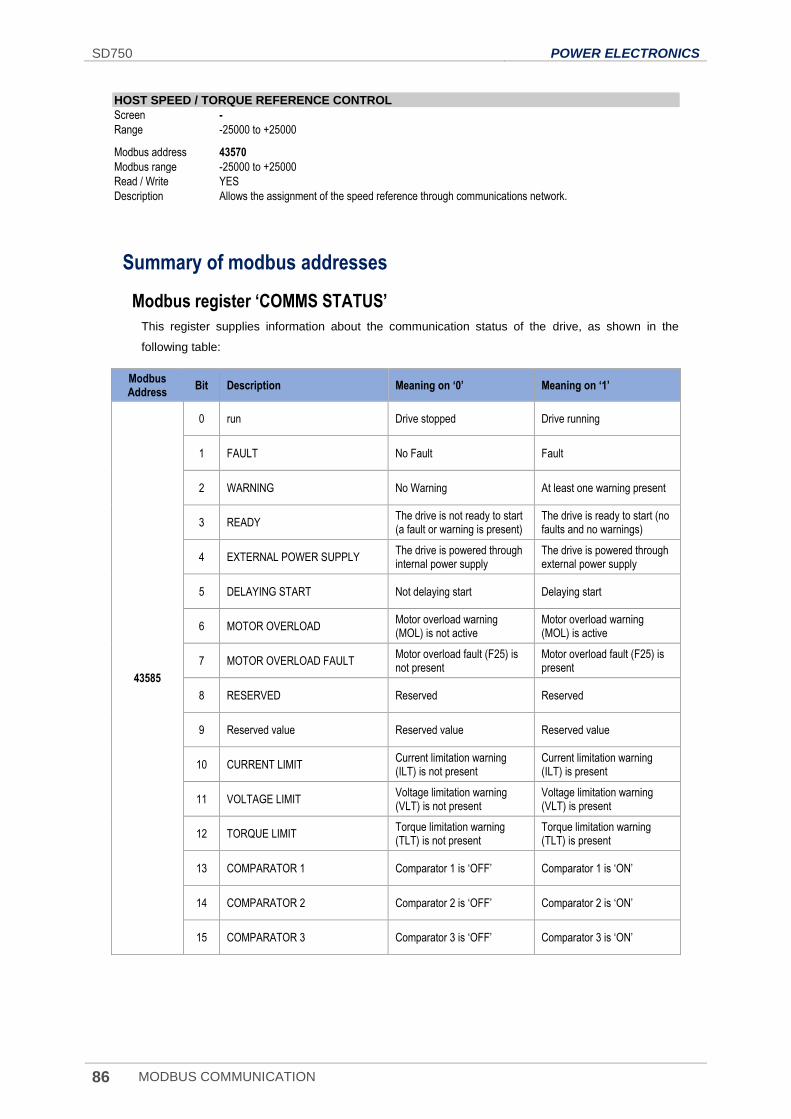
SD750 POWER ELECTRONICS
86 MODBUS COMMUNICATION
HOST SPEED / TORQUE REFERENCE CONTROL
Screen -
Range -25000 to +25000
Modbus address 43570
Modbus range -25000 to +25000
Read / Write YES
Description Allows the assignment of the speed reference through communications network.
Summary of modbus addresses
Modbus register ‘COMMS STATUS’
This register supplies information about the communication status of the drive, as shown in the
following table:
Modbus Address
Bit Description Meaning on ‘0’ Meaning on ‘1’
43585
0 run Drive stopped Drive running
1 FAULT No Fault Fault
2 WARNING No Warning At least one warning present
3 READY The drive is not ready to start (a fault or warning is present)
The drive is ready to start (no faults and no warnings)
4 EXTERNAL POWER SUPPLY The drive is powered through internal power supply
The drive is powered through external power supply
5 DELAYING START Not delaying start Delaying start
6 MOTOR OVERLOAD Motor overload warning (MOL) is not active
Motor overload warning (MOL) is active
7 MOTOR OVERLOAD FAULT Motor overload fault (F25) is not present
Motor overload fault (F25) is present
8 RESERVED Reserved Reserved
9 Reserved value Reserved value Reserved value
10 CURRENT LIMIT Current limitation warning (ILT) is not present
Current limitation warning (ILT) is present
11 VOLTAGE LIMIT Voltage limitation warning (VLT) is not present
Voltage limitation warning (VLT) is present
12 TORQUE LIMIT Torque limitation warning (TLT) is not present
Torque limitation warning (TLT) is present
13 COMPARATOR 1 Comparator 1 is ‘OFF’ Comparator 1 is ‘ON’
14 COMPARATOR 2 Comparator 2 is ‘OFF’ Comparator 2 is ‘ON’
15 COMPARATOR 3 Comparator 3 is ‘OFF’ Comparator 3 is ‘ON’
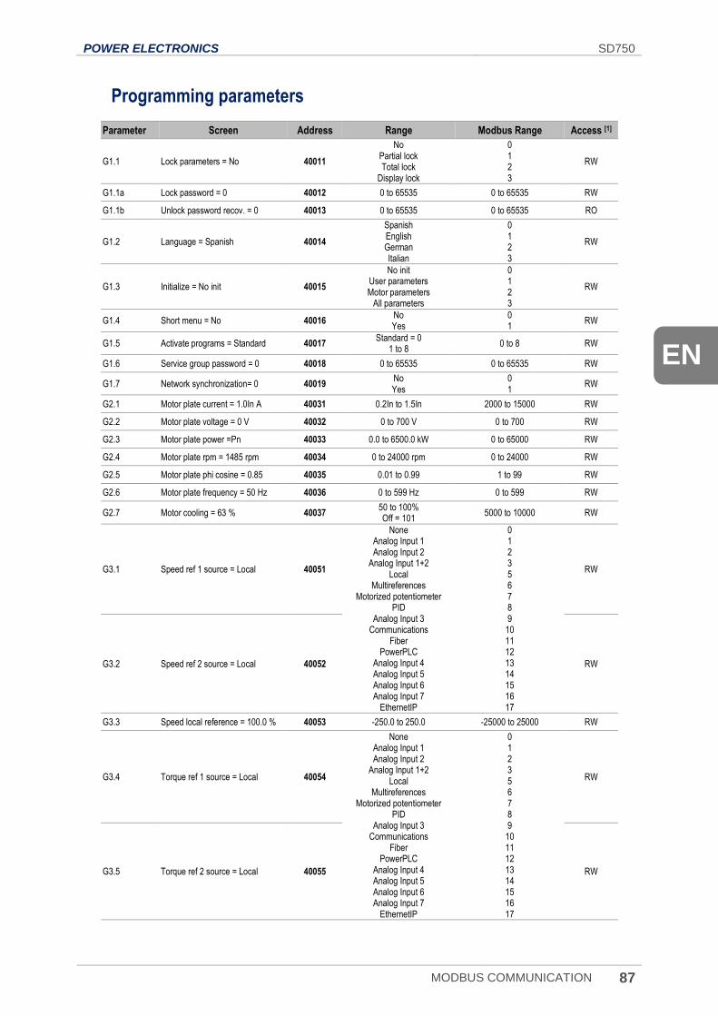
POWER ELECTRONICS SD750
MODBUS COMMUNICATION 87
EN
Programming parameters
Parameter Screen Address Range Modbus Range Access [1]
G1.1 Lock parameters = No 40011
No Partial lock Total lock
Display lock
0 1 2 3
RW
G1.1a Lock password = 0 40012 0 to 65535 0 to 65535 RW
G1.1b Unlock password recov. = 0 40013 0 to 65535 0 to 65535 RO
G1.2 Language = Spanish 40014
Spanish English German Italian
0 1 2 3
RW
G1.3 Initialize = No init 40015
No init User parameters Motor parameters
All parameters
0 1 2 3
RW
G1.4 Short menu = No 40016 No Yes
0 1
RW
G1.5 Activate programs = Standard 40017 Standard = 0
1 to 8 0 to 8 RW
G1.6 Service group password = 0 40018 0 to 65535 0 to 65535 RW
G1.7 Network synchronization= 0 40019 No Yes
0 1
RW
G2.1 Motor plate current = 1.0In A 40031 0.2In to 1.5In 2000 to 15000 RW
G2.2 Motor plate voltage = 0 V 40032 0 to 700 V 0 to 700 RW
G2.3 Motor plate power =Pn 40033 0.0 to 6500.0 kW 0 to 65000 RW
G2.4 Motor plate rpm = 1485 rpm 40034 0 to 24000 rpm 0 to 24000 RW
G2.5 Motor plate phi cosine = 0.85 40035 0.01 to 0.99 1 to 99 RW
G2.6 Motor plate frequency = 50 Hz 40036 0 to 599 Hz 0 to 599 RW
G2.7 Motor cooling = 63 % 40037 50 to 100% Off = 101
5000 to 10000 RW
G3.1 Speed ref 1 source = Local 40051
None Analog Input 1 Analog Input 2
Analog Input 1+2 Local
Multireferences Motorized potentiometer
PID Analog Input 3
Communications Fiber
PowerPLC Analog Input 4 Analog Input 5 Analog Input 6 Analog Input 7
EthernetIP
0 1 2 3 5 6 7 8 9
10 11 12 13 14 15 16 17
RW
G3.2 Speed ref 2 source = Local 40052 RW
G3.3 Speed local reference = 100.0 % 40053 -250.0 to 250.0 -25000 to 25000 RW
G3.4 Torque ref 1 source = Local 40054
None Analog Input 1 Analog Input 2
Analog Input 1+2 Local
Multireferences Motorized potentiometer
PID Analog Input 3
Communications Fiber
PowerPLC Analog Input 4 Analog Input 5 Analog Input 6 Analog Input 7
EthernetIP
0 1 2 3 5 6 7 8 9
10 11 12 13 14 15 16 17
RW
G3.5 Torque ref 2 source = Local 40055 RW
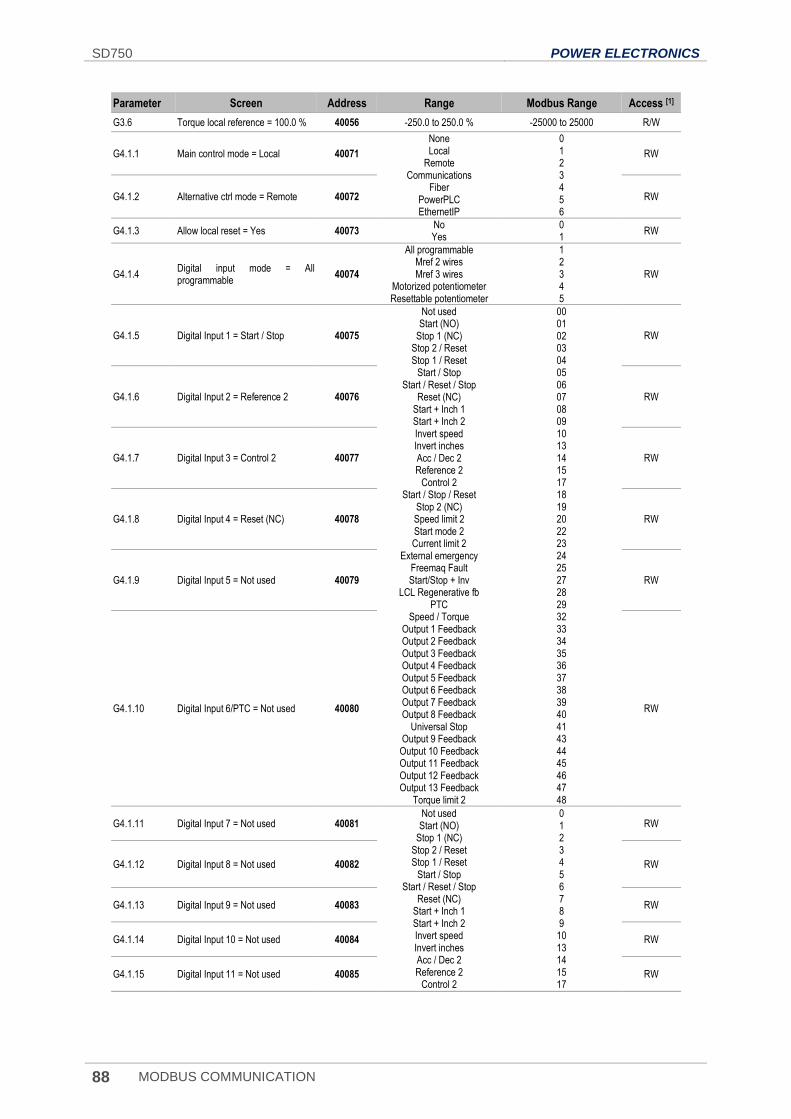
SD750 POWER ELECTRONICS
88 MODBUS COMMUNICATION
Parameter Screen Address Range Modbus Range Access [1]
G3.6 Torque local reference = 100.0 % 40056 -250.0 to 250.0 % -25000 to 25000 R/W
G4.1.1 Main control mode = Local 40071
None Local
Remote Communications
Fiber PowerPLC EthernetIP
0 1 2 3 4 5 6
RW
G4.1.2 Alternative ctrl mode = Remote 40072 RW
G4.1.3 Allow local reset = Yes 40073 No Yes
0 1
RW
G4.1.4 Digital input mode = All programmable
40074
All programmable Mref 2 wires Mref 3 wires
Motorized potentiometer Resettable potentiometer
1 2 3 4 5
RW
G4.1.5 Digital Input 1 = Start / Stop 40075
Not used Start (NO)
Stop 1 (NC) Stop 2 / Reset Stop 1 / Reset
Start / Stop Start / Reset / Stop
Reset (NC) Start + Inch 1 Start + Inch 2 Invert speed Invert inches Acc / Dec 2 Reference 2
Control 2 Start / Stop / Reset
Stop 2 (NC) Speed limit 2 Start mode 2 Current limit 2
External emergency Freemaq Fault Start/Stop + Inv
LCL Regenerative fb PTC
Speed / Torque Output 1 Feedback Output 2 Feedback Output 3 Feedback Output 4 Feedback Output 5 Feedback Output 6 Feedback Output 7 Feedback Output 8 Feedback
Universal Stop Output 9 Feedback Output 10 Feedback Output 11 Feedback Output 12 Feedback Output 13 Feedback
Torque limit 2
00 01 02 03 04 05 06 07 08 09 10 13 14 15 17 18 19 20 22 23 24 25 27 28 29 32 33 34 35 36 37 38 39 40 41 43 44 45 46 47 48
RW
G4.1.6 Digital Input 2 = Reference 2 40076 RW
G4.1.7 Digital Input 3 = Control 2 40077 RW
G4.1.8 Digital Input 4 = Reset (NC) 40078 RW
G4.1.9 Digital Input 5 = Not used 40079 RW
G4.1.10 Digital Input 6/PTC = Not used 40080 RW
G4.1.11 Digital Input 7 = Not used 40081 Not used Start (NO)
Stop 1 (NC) Stop 2 / Reset Stop 1 / Reset
Start / Stop Start / Reset / Stop
Reset (NC) Start + Inch 1 Start + Inch 2 Invert speed Invert inches Acc / Dec 2 Reference 2
Control 2
0 1 2 3 4 5 6 7 8 9
10 13 14 15 17
RW
G4.1.12 Digital Input 8 = Not used 40082 RW
G4.1.13 Digital Input 9 = Not used 40083 RW
G4.1.14 Digital Input 10 = Not used 40084 RW
G4.1.15 Digital Input 11 = Not used 40085 RW
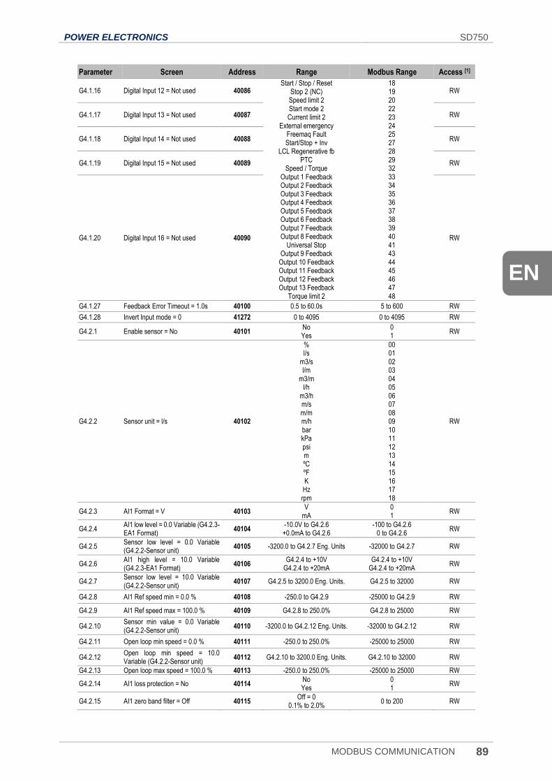
POWER ELECTRONICS SD750
MODBUS COMMUNICATION 89
EN
Parameter Screen Address Range Modbus Range Access [1]
G4.1.16 Digital Input 12 = Not used 40086 Start / Stop / Reset
Stop 2 (NC) Speed limit 2 Start mode 2 Current limit 2
External emergency Freemaq Fault Start/Stop + Inv
LCL Regenerative fb PTC
Speed / Torque Output 1 Feedback Output 2 Feedback Output 3 Feedback Output 4 Feedback Output 5 Feedback Output 6 Feedback Output 7 Feedback Output 8 Feedback
Universal Stop Output 9 Feedback Output 10 Feedback Output 11 Feedback Output 12 Feedback Output 13 Feedback
Torque limit 2
18 19 20 22 23 24 25 27 28 29 32 33 34 35 36 37 38 39 40 41 43 44 45 46 47 48
RW
G4.1.17 Digital Input 13 = Not used 40087 RW
G4.1.18 Digital Input 14 = Not used 40088 RW
G4.1.19 Digital Input 15 = Not used 40089 RW
G4.1.20 Digital Input 16 = Not used 40090 RW
G4.1.27 Feedback Error Timeout = 1.0s 40100 0.5 to 60.0s 5 to 600 RW
G4.1.28 Invert Input mode = 0 41272 0 to 4095 0 to 4095 RW
G4.2.1 Enable sensor = No 40101 No Yes
0 1
RW
G4.2.2 Sensor unit = l/s 40102
% l/s
m3/s l/m
m3/m l/h
m3/h m/s m/m m/h bar kPa psi m ºC ºF K Hz rpm
00 01 02 03 04 05 06 07 08 09 10 11 12 13 14 15 16 17 18
RW
G4.2.3 AI1 Format = V 40103 V
mA 0 1
RW
G4.2.4 AI1 low level = 0.0 Variable (G4.2.3-EA1 Format)
40104 -10.0V to G4.2.6 +0.0mA to G4.2.6
-100 to G4.2.6 0 to G4.2.6
RW
G4.2.5 Sensor low level = 0.0 Variable (G4.2.2-Sensor unit)
40105 -3200.0 to G4.2.7 Eng. Units -32000 to G4.2.7 RW
G4.2.6 AI1 high level = 10.0 Variable (G4.2.3-EA1 Format)
40106 G4.2.4 to +10V
G4.2.4 to +20mA G4.2.4 to +10V
G4.2.4 to +20mA RW
G4.2.7 Sensor low level = 10.0 Variable (G4.2.2-Sensor unit)
40107 G4.2.5 to 3200.0 Eng. Units. G4.2.5 to 32000 RW
G4.2.8 AI1 Ref speed min = 0.0 % 40108 -250.0 to G4.2.9 -25000 to G4.2.9 RW
G4.2.9 AI1 Ref speed max = 100.0 % 40109 G4.2.8 to 250.0% G4.2.8 to 25000 RW
G4.2.10 Sensor min value = 0.0 Variable (G4.2.2-Sensor unit)
40110 -3200.0 to G4.2.12 Eng. Units. -32000 to G4.2.12 RW
G4.2.11 Open loop min speed = 0.0 % 40111 -250.0 to 250.0% -25000 to 25000 RW
G4.2.12 Open loop min speed = 10.0 Variable (G4.2.2-Sensor unit)
40112 G4.2.10 to 3200.0 Eng. Units. G4.2.10 to 32000 RW
G4.2.13 Open loop max speed = 100.0 % 40113 -250.0 to 250.0% -25000 to 25000 RW
G4.2.14 AI1 loss protection = No 40114 No Yes
0 1
RW
G4.2.15 AI1 zero band filter = Off 40115 Off = 0
0.1% to 2.0% 0 to 200 RW
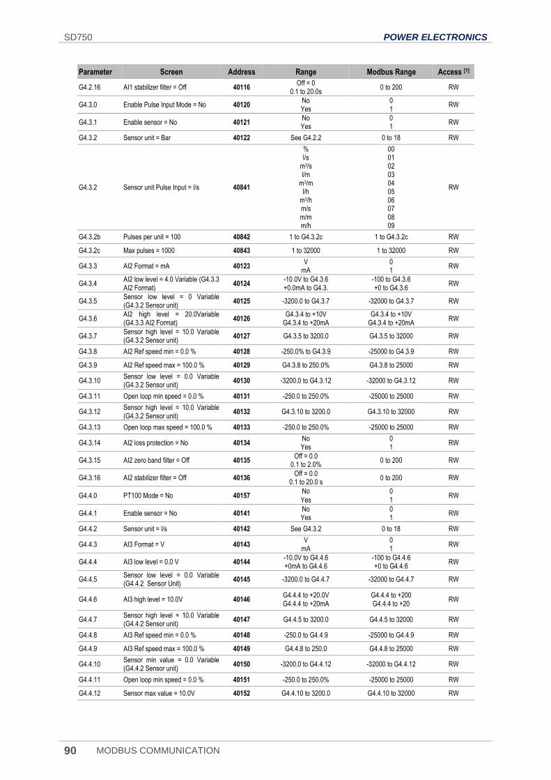
SD750 POWER ELECTRONICS
90 MODBUS COMMUNICATION
Parameter Screen Address Range Modbus Range Access [1]
G4.2.16 AI1 stabilizer filter = Off 40116 Off = 0
0.1 to 20.0s 0 to 200 RW
G4.3.0 Enable Pulse Input Mode = No 40120 No Yes
0 1
RW
G4.3.1 Enable sensor = No 40121 No Yes
0 1
RW
G4.3.2 Sensor unit = Bar 40122 See G4.2.2 0 to 18 RW
G4.3.2 Sensor unit Pulse Input = l/s 40841
% l/s
m3/s l/m
m3/m l/h
m3/h m/s m/m m/h
00 01 02 03 04 05 06 07 08 09
RW
G4.3.2b Pulses per unit = 100 40842 1 to G4.3.2c 1 to G4.3.2c RW
G4.3.2c Max pulses = 1000 40843 1 to 32000 1 to 32000 RW
G4.3.3 AI2 Format = mA 40123 V
mA 0 1
RW
G4.3.4 AI2 low level = 4.0 Variable (G4.3.3 AI2 Format)
40124 -10.0V to G4.3.6 +0.0mA to G4.3.
-100 to G4.3.6 +0 to G4.3.6
RW
G4.3.5 Sensor low level = 0 Variable (G4.3.2 Sensor unit)
40125 -3200.0 to G4.3.7 -32000 to G4.3.7 RW
G4.3.6 AI2 high level = 20.0Variable (G4.3.3 AI2 Format)
40126 G4.3.4 to +10V
G4.3.4 to +20mA G4.3.4 to +10V
G4.3.4 to +20mA RW
G4.3.7 Sensor high level = 10.0 Variable (G4.3.2 Sensor unit)
40127 G4.3.5 to 3200.0 G4.3.5 to 32000 RW
G4.3.8 AI2 Ref speed min = 0.0 % 40128 -250.0% to G4.3.9 -25000 to G4.3.9 RW
G4.3.9 AI2 Ref speed max = 100.0 % 40129 G4.3.8 to 250.0% G4.3.8 to 25000 RW
G4.3.10 Sensor low level = 0.0 Variable (G4.3.2 Sensor unit)
40130 -3200.0 to G4.3.12 -32000 to G4.3.12 RW
G4.3.11 Open loop min speed = 0.0 % 40131 -250.0 to 250.0% -25000 to 25000 RW
G4.3.12 Sensor high level = 10.0 Variable (G4.3.2 Sensor unit)
40132 G4.3.10 to 3200.0 G4.3.10 to 32000 RW
G4.3.13 Open loop max speed = 100.0 % 40133 -250.0 to 250.0% -25000 to 25000 RW
G4.3.14 AI2 loss protection = No 40134 No Yes
0 1
RW
G4.3.15 AI2 zero band filter = Off 40135 Off = 0.0
0.1 to 2.0% 0 to 200 RW
G4.3.16 AI2 stabilizer filter = Off 40136 Off = 0.0
0.1 to 20.0 s 0 to 200 RW
G4.4.0 PT100 Mode = No 40157 No
Yes
0 1
RW
G4.4.1 Enable sensor = No 40141 No Yes
0 1
RW
G4.4.2 Sensor unit = l/s 40142 See G4.3.2 0 to 18 RW
G4.4.3 AI3 Format = V 40143 V
mA 0 1
RW
G4.4.4 AI3 low level = 0.0 V 40144 -10.0V to G4.4.6 +0mA to G4.4.6
-100 to G4.4.6 +0 to G4.4.6
RW
G4.4.5 Sensor low level = 0.0 Variable (G4.4.2 Sensor Unit)
40145 -3200.0 to G4.4.7 -32000 to G4.4.7 RW
G4.4.6 AI3 high level = 10.0V 40146 G4.4.4 to +20.0V G4.4.4 to +20mA
G4.4.4 to +200 G4.4.4 to +20
RW
G4.4.7 Sensor high level = 10.0 Variable (G4.4.2 Sensor unit)
40147 G4.4.5 to 3200.0 G4.4.5 to 32000 RW
G4.4.8 AI3 Ref speed min = 0.0 % 40148 -250.0 to G4.4.9 -25000 to G4.4.9 RW
G4.4.9 AI3 Ref speed max = 100.0 % 40149 G4.4.8 to 250.0 G4.4.8 to 25000 RW
G4.4.10 Sensor min value = 0.0 Variable (G4.4.2 Sensor unit)
40150 -3200.0 to G4.4.12 -32000 to G4.4.12 RW
G4.4.11 Open loop min speed = 0.0 % 40151 -250.0 to 250.0% -25000 to 25000 RW
G4.4.12 Sensor max value = 10.0V 40152 G4.4.10 to 3200.0 G4.4.10 to 32000 RW
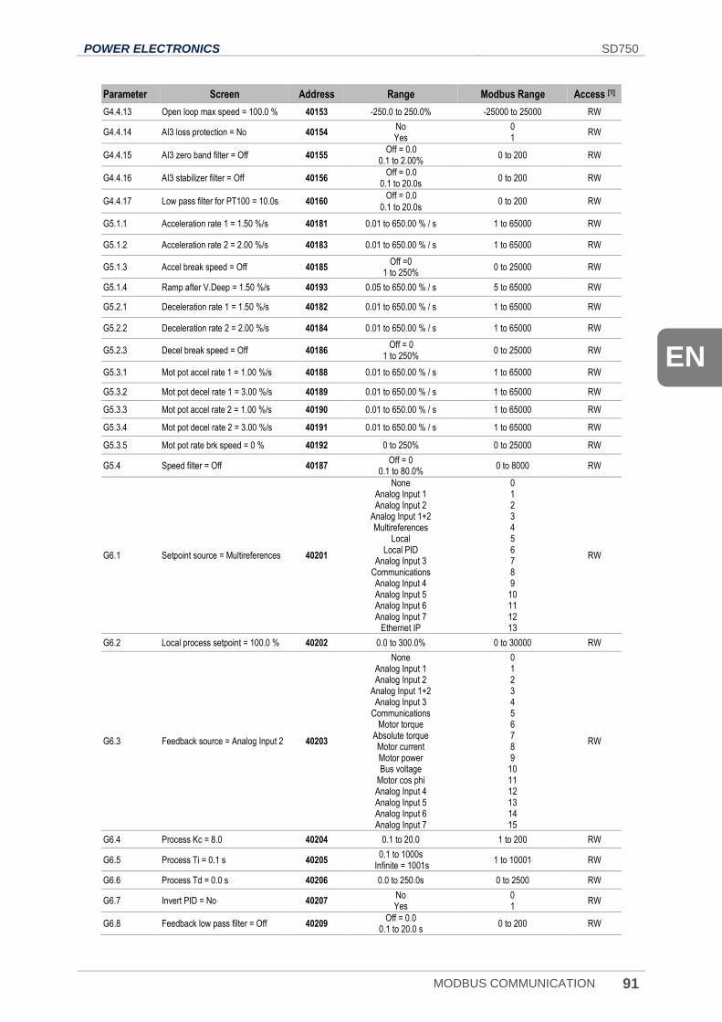
POWER ELECTRONICS SD750
MODBUS COMMUNICATION 91
EN
Parameter Screen Address Range Modbus Range Access [1]
G4.4.13 Open loop max speed = 100.0 % 40153 -250.0 to 250.0% -25000 to 25000 RW
G4.4.14 AI3 loss protection = No 40154 No Yes
0 1
RW
G4.4.15 AI3 zero band filter = Off 40155 Off = 0.0
0.1 to 2.00% 0 to 200 RW
G4.4.16 AI3 stabilizer filter = Off 40156 Off = 0.0
0.1 to 20.0s 0 to 200 RW
G4.4.17 Low pass filter for PT100 = 10.0s 40160 Off = 0.0
0.1 to 20.0s 0 to 200 RW
G5.1.1 Acceleration rate 1 = 1.50 %/s 40181 0.01 to 650.00 % / s 1 to 65000 RW
G5.1.2 Acceleration rate 2 = 2.00 %/s 40183 0.01 to 650.00 % / s 1 to 65000 RW
G5.1.3 Accel break speed = Off 40185 Off =0
1 to 250% 0 to 25000 RW
G5.1.4 Ramp after V.Deep = 1.50 %/s 40193 0.05 to 650.00 % / s 5 to 65000 RW
G5.2.1 Deceleration rate 1 = 1.50 %/s 40182 0.01 to 650.00 % / s 1 to 65000 RW
G5.2.2 Deceleration rate 2 = 2.00 %/s 40184 0.01 to 650.00 % / s 1 to 65000 RW
G5.2.3 Decel break speed = Off 40186 Off = 0
1 to 250% 0 to 25000 RW
G5.3.1 Mot pot accel rate 1 = 1.00 %/s 40188 0.01 to 650.00 % / s 1 to 65000 RW
G5.3.2 Mot pot decel rate 1 = 3.00 %/s 40189 0.01 to 650.00 % / s 1 to 65000 RW
G5.3.3 Mot pot accel rate 2 = 1.00 %/s 40190 0.01 to 650.00 % / s 1 to 65000 RW
G5.3.4 Mot pot decel rate 2 = 3.00 %/s 40191 0.01 to 650.00 % / s 1 to 65000 RW
G5.3.5 Mot pot rate brk speed = 0 % 40192 0 to 250% 0 to 25000 RW
G5.4 Speed filter = Off 40187 Off = 0
0.1 to 80.0% 0 to 8000 RW
G6.1 Setpoint source = Multireferences 40201
None Analog Input 1 Analog Input 2
Analog Input 1+2 Multireferences
Local Local PID
Analog Input 3 Communications Analog Input 4 Analog Input 5 Analog Input 6 Analog Input 7
Ethernet IP
0 1 2 3 4 5 6 7 8 9
10 11 12 13
RW
G6.2 Local process setpoint = 100.0 % 40202 0.0 to 300.0% 0 to 30000 RW
G6.3 Feedback source = Analog Input 2 40203
None Analog Input 1 Analog Input 2
Analog Input 1+2 Analog Input 3
Communications Motor torque
Absolute torque Motor current Motor power Bus voltage
Motor cos phi Analog Input 4 Analog Input 5 Analog Input 6 Analog Input 7
0 1 2 3 4 5 6 7 8 9
10 11 12 13 14 15
RW
G6.4 Process Kc = 8.0 40204 0.1 to 20.0 1 to 200 RW
G6.5 Process Ti = 0.1 s 40205 0.1 to 1000s
Infinite = 1001s 1 to 10001 RW
G6.6 Process Td = 0.0 s 40206 0.0 to 250.0s 0 to 2500 RW
G6.7 Invert PID = No 40207 No Yes
0 1
RW
G6.8 Feedback low pass filter = Off 40209 Off = 0.0
0.1 to 20.0 s 0 to 200 RW
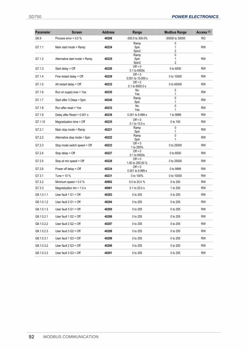
SD750 POWER ELECTRONICS
92 MODBUS COMMUNICATION
Parameter Screen Address Range Modbus Range Access [1]
G6.9 Process error = 0.0 % 40208 -300.0 to 300.0% -30000 to 30000 RO
G7.1.1 Main start mode = Ramp 40224 Ramp Spin
Spin2
0 1 2
RW
G7.1.2 Alternative start mode = Ramp 40225 Ramp Spin
Spin2
0 1 2
RW
G7.1.3 Start delay = Off 40226 Off = 0
0.1 to 6500s 0 to 6500 RW
G7.1.4 Fine restart delay = Off 40229 Off = 0
0.001 to 10.000 s 0 to 10000 RW
G7.1.5 Alt restart delay = Off 40232 Off = 0
0.1 to 6500.0 s 0 to 65000 RW
G7.1.6 Run on supply loss = Yes 40230 No Yes
0 1
RW
G7.1.7 Start after V.Deep = Spin 40240 Ramp Spin
0 1
RW
G7.1.8 Run after reset = Yes 40233 No Yes
0 1
RW
G7.1.9 Delay after Reset = 0.001 s 40236 0.001 to 9.999 s 1 to 9999 RW
G7.1.10 Magnetization time = Off 40235 Off = 0
0.1 to 10.0 s 0 to 100 RW
G7.2.1 Main stop mode = Ramp 40221 Ramp Spin
0 1
RW
G7.2.2 Alternative stop mode = Spin 40222 Ramp Spin
0 1
RW
G7.2.3 Stop mode switch speed = Off 40223 Off = 0
1 to 250% 0 to 25000 RW
G7.2.4 Stop delay = Off 40227 Off = 0
0.1 to 6500s 0 to 6500 RW
G7.2.5 Stop at min speed = Off 40228 Off = 0
1.00 to 250.00 % 0 to 25000 RW
G7.2.6 Power off delay = Off 40234 Off = 0
0.001 to 9.999 s 0 to 9999 RW
G7.3.1 Tune = 10 % 40231 0 to 100% 0 to 10000 RW
G7.3.2 Minimum speed = 0.0 % 40982 0.0 to 25.0 % 0 to 250 RW
G7.3.3 Magnetization tim = 1.0 s 40981 0.1 to 25.0 s 1 to 250 RW
G8.1.0.1.1 User fault 1 G1 = Off 40283 0 to 255 0 to 255 RW
G8.1.0.1.2 User fault 2 G1 = Off 40284 0 to 255 0 to 255 RW
G8.1.0.1.3 User fault 3 G1 = Off 40285 0 to 255 0 to 255 RW
G8.1.0.2.1 User fault 1 G2 = Off 40286 0 to 255 0 to 255 RW
G8.1.0.2.2 User fault 2 G2 = Off 40287 0 to 255 0 to 255 RW
G8.1.0.2.3 User fault 3 G2 = Off 40288 0 to 255 0 to 255 RW
G8.1.0.3.1 User fault 1 G3 = Off 40289 0 to 255 0 to 255 RW
G8.1.0.3.2 User fault 2 G3 = Off 40290 0 to 255 0 to 255 RW
G8.1.0.3.3 User fault 3 G3 = Off 40291 0 to 255 0 to 255 RW
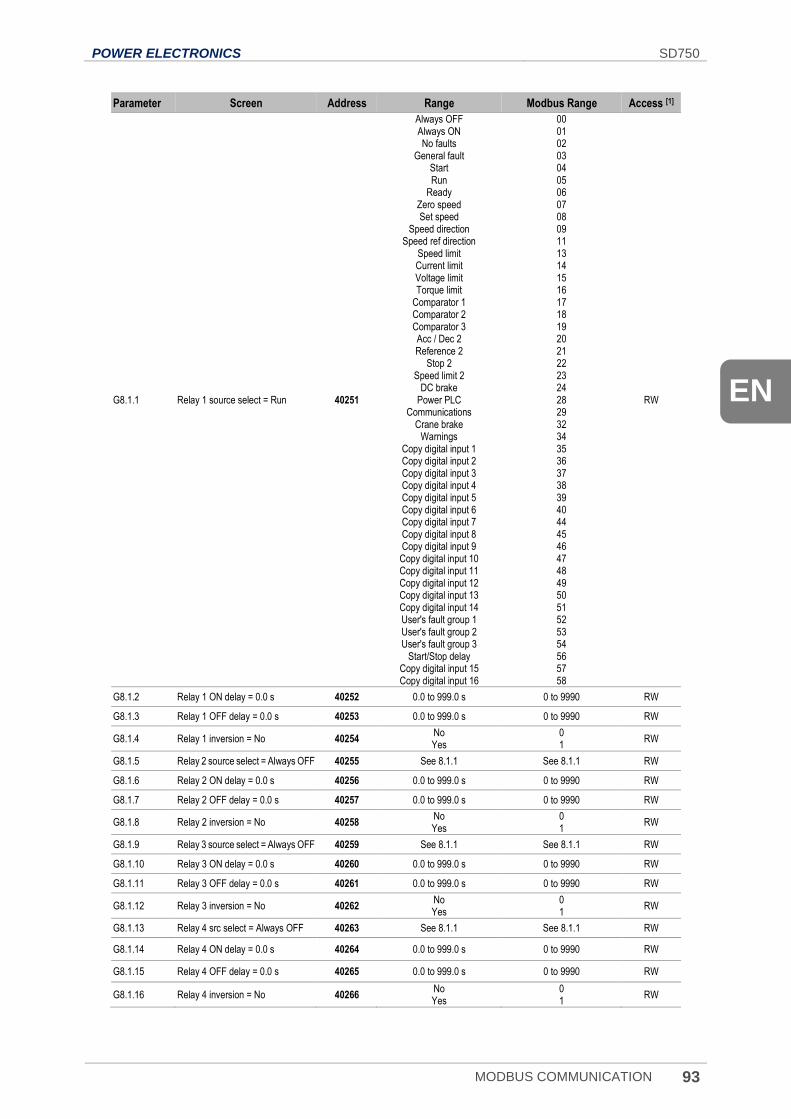
POWER ELECTRONICS SD750
MODBUS COMMUNICATION 93
EN
Parameter Screen Address Range Modbus Range Access [1]
G8.1.1 Relay 1 source select = Run 40251
Always OFF Always ON No faults
General fault Start Run
Ready Zero speed Set speed
Speed direction Speed ref direction
Speed limit Current limit Voltage limit Torque limit
Comparator 1 Comparator 2 Comparator 3 Acc / Dec 2 Reference 2
Stop 2 Speed limit 2
DC brake Power PLC
Communications Crane brake
Warnings Copy digital input 1 Copy digital input 2 Copy digital input 3 Copy digital input 4 Copy digital input 5 Copy digital input 6 Copy digital input 7 Copy digital input 8 Copy digital input 9 Copy digital input 10 Copy digital input 11 Copy digital input 12 Copy digital input 13 Copy digital input 14 User's fault group 1 User's fault group 2 User's fault group 3
Start/Stop delay Copy digital input 15 Copy digital input 16
00 01 02 03 04 05 06 07 08 09 11 13 14 15 16 17 18 19 20 21 22 23 24 28 29 32 34 35 36 37 38 39 40 44 45 46 47 48 49 50 51 52 53 54 56 57 58
RW
G8.1.2 Relay 1 ON delay = 0.0 s 40252 0.0 to 999.0 s 0 to 9990 RW
G8.1.3 Relay 1 OFF delay = 0.0 s 40253 0.0 to 999.0 s 0 to 9990 RW
G8.1.4 Relay 1 inversion = No 40254 No Yes
0 1
RW
G8.1.5 Relay 2 source select = Always OFF 40255 See 8.1.1 See 8.1.1 RW
G8.1.6 Relay 2 ON delay = 0.0 s 40256 0.0 to 999.0 s 0 to 9990 RW
G8.1.7 Relay 2 OFF delay = 0.0 s 40257 0.0 to 999.0 s 0 to 9990 RW
G8.1.8 Relay 2 inversion = No 40258 No Yes
0 1
RW
G8.1.9 Relay 3 source select = Always OFF 40259 See 8.1.1 See 8.1.1 RW
G8.1.10 Relay 3 ON delay = 0.0 s 40260 0.0 to 999.0 s 0 to 9990 RW
G8.1.11 Relay 3 OFF delay = 0.0 s 40261 0.0 to 999.0 s 0 to 9990 RW
G8.1.12 Relay 3 inversion = No 40262 No Yes
0 1
RW
G8.1.13 Relay 4 src select = Always OFF 40263 See 8.1.1 See 8.1.1 RW
G8.1.14 Relay 4 ON delay = 0.0 s 40264 0.0 to 999.0 s 0 to 9990 RW
G8.1.15 Relay 4 OFF delay = 0.0 s 40265 0.0 to 999.0 s 0 to 9990 RW
G8.1.16 Relay 4 inversion = No 40266 No Yes
0 1
RW
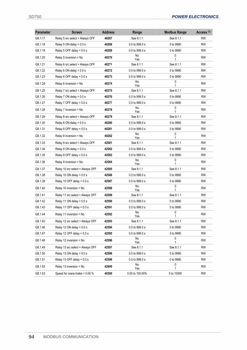
SD750 POWER ELECTRONICS
94 MODBUS COMMUNICATION
Parameter Screen Address Range Modbus Range Access [1]
G8.1.17 Relay 5 src select = Always OFF 40267 See 8.1.1 See 8.1.1 RW
G8.1.18 Relay 5 ON delay = 0.0 s 40268 0.0 to 999.0 s 0 to 9990 RW
G8.1.19 Relay 5 OFF delay = 0.0 s 40269 0.0 to 999.0 s 0 to 9990 RW
G8.1.20 Relay 5 inversion = No 40270 No Yes
0 1
RW
G8.1.21 Relay 6 src select = Always OFF 40271 See 8.1.1 See 8.1.1 RW
G8.1.22 Relay 6 ON delay = 0.0 s 40272 0.0 to 999.0 s 0 to 9990 RW
G8.1.23 Relay 6 OFF delay = 0.0 s 40273 0.0 to 999.0 s 0 to 9990 RW
G8.1.24 Relay 6 inversion = No 40274 No Yes
0 1
RW
G8.1.25 Relay 7 src select = Always OFF 40275 See 8.1.1 See 8.1.1 RW
G8.1.26 Relay 7 ON delay = 0.0 s 40276 0.0 to 999.0 s 0 to 9990 RW
G8.1.27 Relay 7 OFF delay = 0.0 s 40277 0.0 to 999.0 s 0 to 9990 RW
G8.1.28 Relay 7 inversion = No 40278 No Yes
0 1
RW
G8.1.29 Relay 8 src select = Always OFF 40279 See 8.1.1 See 8.1.1 RW
G8.1.30 Relay 8 ON delay = 0.0 s 40280 0.0 to 999.0 s 0 to 9990 RW
G8.1.31 Relay 8 OFF delay = 0.0 s 40281 0.0 to 999.0 s 0 to 9990 RW
G8.1.32 Relay 8 inversion = No 40282 No Yes
0 1
RW
G8.1.33 Relay 9 src select = Always OFF 42581 See 8.1.1 See 8.1.1 RW
G8.1.34 Relay 9 ON delay = 0.0 s 42582 0.0 to 999.0 s 0 to 9990 RW
G8.1.35 Relay 9 OFF delay = 0.0 s 42583 0.0 to 999.0 s 0 to 9990 RW
G8.1.36 Relay 9 inversion = No 42584 No Yes
0 1
RW
G8.1.37 Relay 10 src select = Always OFF 42585 See 8.1.1 See 8.1.1 RW
G8.1.38 Relay 10 ON delay = 0.0 s 42586 0.0 to 999.0 s 0 to 9990 RW
G8.1.39 Relay 10 OFF delay = 0.0 s 42587 0.0 to 999.0 s 0 to 9990 RW
G8.1.40 Relay 10 inversion = No 42588 No Yes
0 1
RW
G8.1.41 Relay 11 src select = Always OFF 42589 See 8.1.1 See 8.1.1 RW
G8.1.42 Relay 11 ON delay = 0.0 s 42590 0.0 to 999.0 s 0 to 9990 RW
G8.1.43 Relay 11 OFF delay = 0.0 s 42591 0.0 to 999.0 s 0 to 9990 RW
G8.1.44 Relay 11 inversion = No 42592 No Yes
0 1
RW
G8.1.45 Relay 12 src select = Always OFF 42593 See 8.1.1 See 8.1.1 RW
G8.1.46 Relay 12 ON delay = 0.0 s 42594 0.0 to 999.0 s 0 to 9990 RW
G8.1.47 Relay 12 OFF delay = 0.0 s 42595 0.0 to 999.0 s 0 to 9990 RW
G8.1.48 Relay 12 inversion = No 42596 No Yes
0 1
RW
G8.1.49 Relay 13 src select = Always OFF 42597 See 8.1.1 See 8.1.1 RW
G8.1.50 Relay 13 ON delay = 0.0 s 42598 0.0 to 999.0 s 0 to 9990 RW
G8.1.51 Relay 13 OFF delay = 0.0 s 42599 0.0 to 999.0 s 0 to 9990 RW
G8.1.52 Relay 13 inversion = No 42600 No Yes
0 1
RW
G8.1.53 Speed for crane brake = 0.00 % 40300 0.00 to 100.00% 0 to 10000 RW
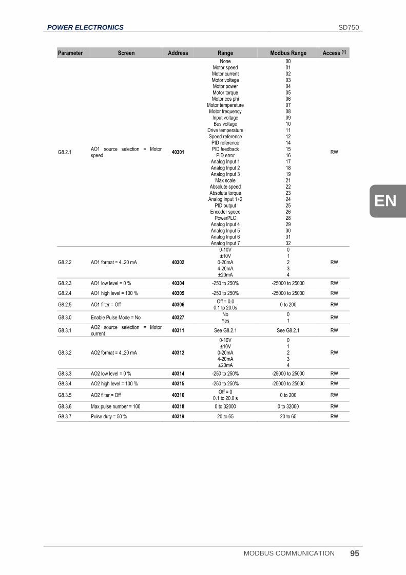
POWER ELECTRONICS SD750
MODBUS COMMUNICATION 95
EN
Parameter Screen Address Range Modbus Range Access [1]
G8.2.1 AO1 source selection = Motor speed
40301
None Motor speed Motor current Motor voltage Motor power Motor torque Motor cos phi
Motor temperature Motor frequency
Input voltage Bus voltage
Drive temperature Speed reference
PID reference PID feedback
PID error Analog Input 1 Analog Input 2 Analog Input 3
Max scale Absolute speed Absolute torque
Analog Input 1+2 PID output
Encoder speed PowerPLC
Analog Input 4 Analog Input 5 Analog Input 6 Analog Input 7
00 01 02 03 04 05 06 07 08 09 10 11 12 14 15 16 17 18 19 21 22 23 24 25 26 28 29 30 31 32
RW
G8.2.2 AO1 format = 4..20 mA 40302
0-10V ±10V
0-20mA 4-20mA ±20mA
0 1 2 3 4
RW
G8.2.3 AO1 low level = 0 % 40304 -250 to 250% -25000 to 25000 RW
G8.2.4 AO1 high level = 100 % 40305 -250 to 250% -25000 to 25000 RW
G8.2.5 AO1 filter = Off 40306 Off = 0.0
0.1 to 20.0s 0 to 200 RW
G8.3.0 Enable Pulse Mode = No 40327 No Yes
0 1
RW
G8.3.1 AO2 source selection = Motor current
40311 See G8.2.1 See G8.2.1 RW
G8.3.2 AO2 format = 4..20 mA 40312
0-10V ±10V
0-20mA 4-20mA ±20mA
0 1 2 3 4
RW
G8.3.3 AO2 low level = 0 % 40314 -250 to 250% -25000 to 25000 RW
G8.3.4 AO2 high level = 100 % 40315 -250 to 250% -25000 to 25000 RW
G8.3.5 AO2 filter = Off 40316 Off = 0
0.1 to 20.0 s 0 to 200 RW
G8.3.6 Max pulse number = 100 40318 0 to 32000 0 to 32000 RW
G8.3.7 Pulse duty = 50 % 40319 20 to 65 20 to 65 RW
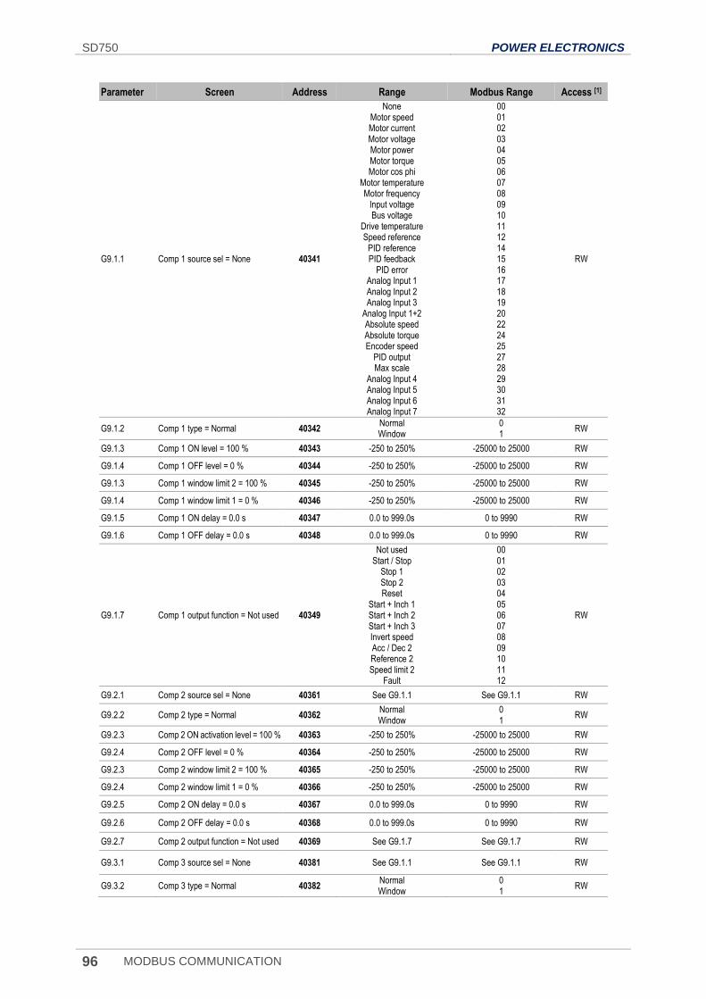
SD750 POWER ELECTRONICS
96 MODBUS COMMUNICATION
Parameter Screen Address Range Modbus Range Access [1]
G9.1.1 Comp 1 source sel = None 40341
None Motor speed Motor current Motor voltage Motor power Motor torque Motor cos phi
Motor temperature Motor frequency
Input voltage Bus voltage
Drive temperature Speed reference
PID reference PID feedback
PID error Analog Input 1 Analog Input 2 Analog Input 3
Analog Input 1+2 Absolute speed Absolute torque Encoder speed
PID output Max scale
Analog Input 4 Analog Input 5 Analog Input 6 Analog Input 7
00 01 02 03 04 05 06 07 08 09 10 11 12 14 15 16 17 18 19 20 22 24 25 27 28 29 30 31 32
RW
G9.1.2 Comp 1 type = Normal 40342 Normal Window
0 1
RW
G9.1.3 Comp 1 ON level = 100 % 40343 -250 to 250% -25000 to 25000 RW
G9.1.4 Comp 1 OFF level = 0 % 40344 -250 to 250% -25000 to 25000 RW
G9.1.3 Comp 1 window limit 2 = 100 % 40345 -250 to 250% -25000 to 25000 RW
G9.1.4 Comp 1 window limit 1 = 0 % 40346 -250 to 250% -25000 to 25000 RW
G9.1.5 Comp 1 ON delay = 0.0 s 40347 0.0 to 999.0s 0 to 9990 RW
G9.1.6 Comp 1 OFF delay = 0.0 s 40348 0.0 to 999.0s 0 to 9990 RW
G9.1.7 Comp 1 output function = Not used 40349
Not used Start / Stop
Stop 1 Stop 2 Reset
Start + Inch 1 Start + Inch 2 Start + Inch 3 Invert speed Acc / Dec 2 Reference 2 Speed limit 2
Fault
00 01 02 03 04 05 06 07 08 09 10 11 12
RW
G9.2.1 Comp 2 source sel = None 40361 See G9.1.1 See G9.1.1 RW
G9.2.2 Comp 2 type = Normal 40362 Normal Window
0 1
RW
G9.2.3 Comp 2 ON activation level = 100 % 40363 -250 to 250% -25000 to 25000 RW
G9.2.4 Comp 2 OFF level = 0 % 40364 -250 to 250% -25000 to 25000 RW
G9.2.3 Comp 2 window limit 2 = 100 % 40365 -250 to 250% -25000 to 25000 RW
G9.2.4 Comp 2 window limit 1 = 0 % 40366 -250 to 250% -25000 to 25000 RW
G9.2.5 Comp 2 ON delay = 0.0 s 40367 0.0 to 999.0s 0 to 9990 RW
G9.2.6 Comp 2 OFF delay = 0.0 s 40368 0.0 to 999.0s 0 to 9990 RW
G9.2.7 Comp 2 output function = Not used 40369 See G9.1.7 See G9.1.7 RW
G9.3.1 Comp 3 source sel = None 40381 See G9.1.1 See G9.1.1 RW
G9.3.2 Comp 3 type = Normal 40382 Normal Window
0 1
RW
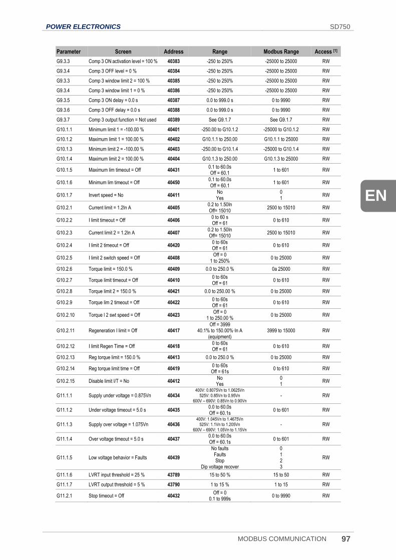
POWER ELECTRONICS SD750
MODBUS COMMUNICATION 97
EN
Parameter Screen Address Range Modbus Range Access [1]
G9.3.3 Comp 3 ON activation level = 100 % 40383 -250 to 250% -25000 to 25000 RW
G9.3.4 Comp 3 OFF level = 0 % 40384 -250 to 250% -25000 to 25000 RW
G9.3.3 Comp 3 window limit 2 = 100 % 40385 -250 to 250% -25000 to 25000 RW
G9.3.4 Comp 3 window limit 1 = 0 % 40386 -250 to 250% -25000 to 25000 RW
G9.3.5 Comp 3 ON delay = 0.0 s 40387 0.0 to 999.0 s 0 to 9990 RW
G9.3.6 Comp 3 OFF delay = 0.0 s 40388 0.0 to 999.0 s 0 to 9990 RW
G9.3.7 Comp 3 output function = Not used 40389 See G9.1.7 See G9.1.7 RW
G10.1.1 Minimum limit 1 = -100.00 % 40401 -250.00 to G10.1.2 -25000 to G10.1.2 RW
G10.1.2 Maximum limit 1 = 100.00 % 40402 G10.1.1 to 250.00 G10.1.1 to 25000 RW
G10.1.3 Minimum limit 2 = -100.00 % 40403 -250.00 to G10.1.4 -25000 to G10.1.4 RW
G10.1.4 Maximum limit 2 = 100.00 % 40404 G10.1.3 to 250.00 G10.1.3 to 25000 RW
G10.1.5 Maximum lim timeout = Off 40431 0.1 to 60.0s Off = 60.1
1 to 601 RW
G10.1.6 Minimum lim timeout = Off 40450 0.1 to 60.0s Off = 60.1
1 to 601 RW
G10.1.7 Invert speed = No 40411 No Yes
0 1
RW
G10.2.1 Current limit = 1.2In A 40405 0.2 to 1.50In Off= 15010
2500 to 15010 RW
G10.2.2 I limit timeout = Off 40406 0 to 60 s Off = 61
0 to 610 RW
G10.2.3 Current limit 2 = 1.2In A 40407 0.2 to 1.50In Off= 15010
2500 to 15010 RW
G10.2.4 I limit 2 timeout = Off 40420 0 to 60s Off = 61
0 to 610 RW
G10.2.5 I limit 2 switch speed = Off 40408 Off = 0
1 to 250% 0 to 25000 RW
G10.2.6 Torque limit = 150.0 % 40409 0.0 to 250.0 % 0a 25000 RW
G10.2.7 Torque limit timeout = Off 40410 0 to 60s Off = 61
0 to 610 RW
G10.2.8 Torque limit 2 = 150.0 % 40421 0.0 to 250.00 % 0 to 25000 RW
G10.2.9 Torque lim 2 timeout = Off 40422 0 to 60s Off = 61
0 to 610 RW
G10.2.10 Torque l 2 swt speed = Off 40423 Off = 0
1 to 250.00 % 0 to 25000 RW
G10.2.11 Regeneration I limit = Off 40417 Off = 3999
40.1% to 150.00%·In A (equipment)
3999 to 15000 RW
G10.2.12 I limit Regen Time = Off 40418 0 to 60s Off = 61
0 to 610 RW
G10.2.13 Reg torque limit = 150.0 % 40413 0.0 to 250.0 % 0 to 25000 RW
G10.2.14 Reg torque limit time = Off 40419 0 to 60s Off = 61s
0 to 610 RW
G10.2.15 Disable limit I/T = No 40412 No Yes
0 1
RW
G11.1.1 Supply under voltage = 0.875Vn 40434 400V: 0.8075Vn to 1.0625Vn
525V: 0.85Vn to 0.95Vn 600V – 690V: 0.85Vn to 0.90Vn
- RW
G11.1.2 Under voltage timeout = 5.0 s 40435 0.0 to 60.0s Off = 60.1s
0 to 601 RW
G11.1.3 Supply over voltage = 1.075Vn 40436 400V: 1.045Vn to 1.4675Vn
525V: 1.1Vn to 1.205Vn 600V – 690V: 1.05Vn to 1.15Vn
- RW
G11.1.4 Over voltage timeout = 5.0 s 40437 0.0 to 60.0s Off = 60.1s
0 to 601 RW
G11.1.5 Low voltage behavior = Faults 40439
No faults Faults Stop
Dip voltage recover
0 1 2 3
RW
G11.1.6 LVRT input threshold = 25 % 43789 15 to 50 % 15 to 50 RW
G11.1.7 LVRT output threshold = 5 % 43790 1 to 15 % 1 to 15 RW
G11.2.1 Stop timeout = Off 40432 Off = 0
0.1 to 999s 0 to 9990 RW
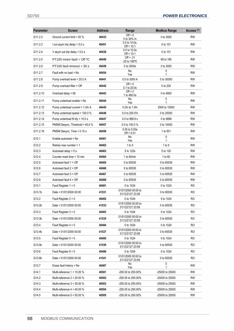
SD750 POWER ELECTRONICS
98 MODBUS COMMUNICATION
Parameter Screen Address Range Modbus Range Access [1]
G11.2.2 Ground current limit = 20 % 40433 Off = 0
0 to 30% In 0 to 3000 RW
G11.2.3 I out asym trip delay = 5.0 s 40451 0.0 to 10.0s, Off = 10.1
0 to 101 RW
G11.2.4 V asym out trip delay = 5.0 s 40438 0.0 to 10.0s Off = 10.1
0 to 101 RW
G11.2.5 PT100 motor fault = Off ºC 40440 Off = -21
-20 to 180ºC 69 to 180 RW
G11.2.6 PT100 fault timeout = 30 s 40459 0 to 3000s 0 to 3000 RW
G11.2.7 Fault with no load = No 40454 No Yes
0 1
RW
G11.2.8 Pump overload level = 20.0 A 40441 0.0 to 3000 A 0 to 30000 RW
G11.2.9 Pump overload filter = Off 40442 Off = 0
0.1 to 20.0s 0 to 200 RW
G11.2.10 Overload delay = 60 40443 Off = 0
1 to 480.0s 0 to 4800 RW
G11.2.11 Pump underload enable = No 40444 No Yes
0 1
RW
G11.2.12 Pump underload current = 1.0In A 40445 0.2In to 1.5In 2000 to 15000 RW
G11.2.13 Pump underload speed = 100.0 % 40446 0.0 to 250.0% 0 to 25000 RW
G11.2.14 Pump underload flt dly = 10.0 s 40447 0.0 to 999.9 s 0 to 9999 RW
G11.2.15 PMSM Desync. Threshold = 40.0 % 40457 0.0 to 100.0 % 0 to 10000 RW
G11.2.16 PMSM Desync. Time = 0.10 s 40458 0.00 to 5.00s
Off = 5.01 1 to 501 RW
G12.1 Enable autoreset = No 40461 No Yes
0 1
RW
G12.2 Retries max number = 1 40462 1 to 5 1 to 5 RW
G12.3 Autoreset delay = 5 s 40463 5 to 120s 5 to 120 RW
G12.4 Counter reset time = 15 min 40464 1 to 60min 1 to 60 RW
G12.5 Autoreset fault 1 = Off 40465 0 to 65535 0 to 65535 RW
G12.6 Autoreset fault 2 = Off 40466 0 to 65535 0 to 65535 RW
G12.7 Autoreset fault 3 = Off 40467 0 to 65535 0 to 65535 RW
G12.8 Autoreset fault 4 = Off 40468 0 to 65535 0 to 65535 RW
G13.1 Fault Register 1 = 0 40481 0 to 1024 0 to 1024 RO
G13.1b Date = 01/01/2000 00:00 41531 01/01/2000 00:00 to 31/12/2127 23:59
0 to 65535 RO
G13.2 Fault Register 2 = 0 40482 0 to 1024 0 to 1024 RO
G13.2b Date = 01/01/2000 00:00 41533 01/01/2000 00:00 to 31/12/2127 23:59
0 to 65535 RO
G13.3 Fault Register 3 = 0 40483 0 to 1024 0 to 1024 RO
G13.3b Date = 01/01/2000 00:00 41535 01/01/2000 00:00 to 31/12/2127 23:59
0 to 65535 RO
G13.4 Fault Register 4 = 0 40484 0 to 1024 0 to 1024 RO
G13.4b Date = 01/01/2000 00:00 41537 01/01/2000 00:00 to 31/12/2127 23:59
0 to 65535 RO
G13.5 Fault Register 5 = 0 40485 0 to 1024 0 to 1024 RO
G13.5b Date = 01/01/2000 00:00 41539 01/01/2000 00:00 to 31/12/2127 23:59
0 to 65535 RO
G13.6 Fault Register 6 = 0 40486 0 to 1024 0 to 1024 RO
G13.6b Date = 01/01/2000 00:00 41541 01/01/2000 00:00 to 31/12/2127 23:59
0 to 65535 RO
G13.7 Erase fault history = No 40487 No Yes
0 1
RW
G14.1 Multi-reference 1 = 10.00 % 40501 -250.00 to 250.00% -25000 to 25000 RW
G14.2 Multi-reference 2 = 20.00 % 40502 -250.00 to 250.00% -25000 to 25000 RW
G14.3 Multi-reference 3 = 30.00 % 40503 -250.00 to 250.00% -25000 to 25000 RW
G14.4 Multi-reference 4 = 40.00 % 40504 -250.00 to 250.00% -25000 to 25000 RW
G14.5 Multi-reference 5 = 50.00 % 40505 -250.00 to 250.00% -25000 to 25000 RW
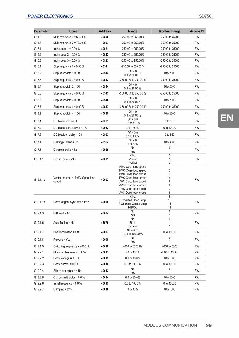
POWER ELECTRONICS SD750
MODBUS COMMUNICATION 99
EN
Parameter Screen Address Range Modbus Range Access [1]
G14.6 Multi-reference 6 = 60.00 % 40506 -250.00 to 250.00% -25000 to 25000 RW
G14.7 Multi-reference 7 = 70.00 % 40507 -250.00 to 250.00% -25000 to 25000 RW
G15.1 Inch speed 1 = 0.00 % 40521 -250.00 to 250.00% -25000 to 25000 RW
G15.2 Inch speed 2 = 0.00 % 40522 -250.00 to 250.00% -25000 to 25000 RW
G15.3 Inch speed 3 = 0.00 % 40523 -250.00 to 250.00% -25000 to 25000 RW
G16.1 Skip frequency 1 = 0.00 % 40541 -250.00 to 250.00 % -25000 to 25000 RW
G16.2 Skip bandwidth 1 = Off 40542 Off = 0
0.1 to 20.00 % 0 to 2000 RW
G16.3 Skip frequency 2 = 0.00 % 40543 -250.00 % to 250.00 % -25000 to 25000 RW
G16.4 Skip bandwidth 2 = Off 40544 Off = 0
0.1 to 20.00 % 0 to 2000 RW
G16.5 Skip frequency 3 = 0.00 % 40545 -250.00 % to 250.00 % -25000 to 25000 RW
G16.6 Skip bandwidth 3 = Off 40546 Off = 0
0.1 to 20.00 % 0 to 2000 RW
G16.7 Skip frequency 4 = 0.00 % 40547 -250.00 % to 250.00 % -25000 to 25000 RW
G16.8 Skip bandwidth 4 = Off 40548 Off = 0
0.1 to 20.00 % 0 to 2000 RW
G17.1 DC brake time = Off 40561 Off = 0.0
0.1 to 99.0s 0 to 990 RW
G17.2 DC brake current level = 0 % 40562 0 to 100% 0 to 10000 RW
G17.3 DC break on delay = Off 40563 Off = 0.0
0.0 to 99.0s 0 to 990 RW
G17.4 Heating current = Off 40564 Off = 0
1 to 30% 0 to 3000 RW
G17.5 Dynamic brake = No 40565 No Yes
0 1
RW
G19.1.1 Control type = V/Hz 40601 V/Hz
Vector PMSM
0 1 2
RW
G19.1.1b Vector control = PMC Open loop speed
40602
PMC Open loop speed PMC Close loop speed PMC Close loop torque PMC Open loop torque AVC Close loop speed AVC Close loop torque AVC Open loop speed AVC Open loop torque
1 2 3 4 5 6 7 8
RW
G19.1.1c Perm Magnet Sync Mot = I/Hz 40608
V/Hz F.Oriented Open Loop
F.Oriented Closed Loop HEPOL
9 10 11 12
RW
G19.1.3 PID Vout = No 40604 No Yes
0 1
RW
G19.1.6 Auto Tuning = No 43575 No
Static Dynamic
0 1 2
RW
G19.1.7 Overmodulation = Off 40607 Off = 0.00
0.01 to 100.00 % 0 to 10000 RW
G19.1.8 Pewave = Yes 40609 No Yes
0 1
RW
G19.1.9 Switching frequency = 4000 Hz 40618 4000 to 8000 Hz 4000 to 8000 RW
G19.2.1 Minimum flux level = 100 % 40611 40 to 130% 4000 to 13000 RW
G19.2.2 Boost voltage = 0.0 % 40612 0.0 to 10.0% 0 to 1000 RW
G19.2.3 Boost current = 0.0 % 40610 0.0 to 100.0% 0 to 10000 RW
G19.2.4 Slip compensation = No 40613 No Yes
0 1
RW
G19.2.5 Current limit factor = 0.0 % 40614 0.0 to 20.0% 0 to 2000 RW
G19.2.6 Initial frequency = 0.0 % 40615 0.0 to 100.0% 0 to 10000 RW
G19.2.7 Damping = 2 % 40616 0 to 10% 0 to 1000 RW
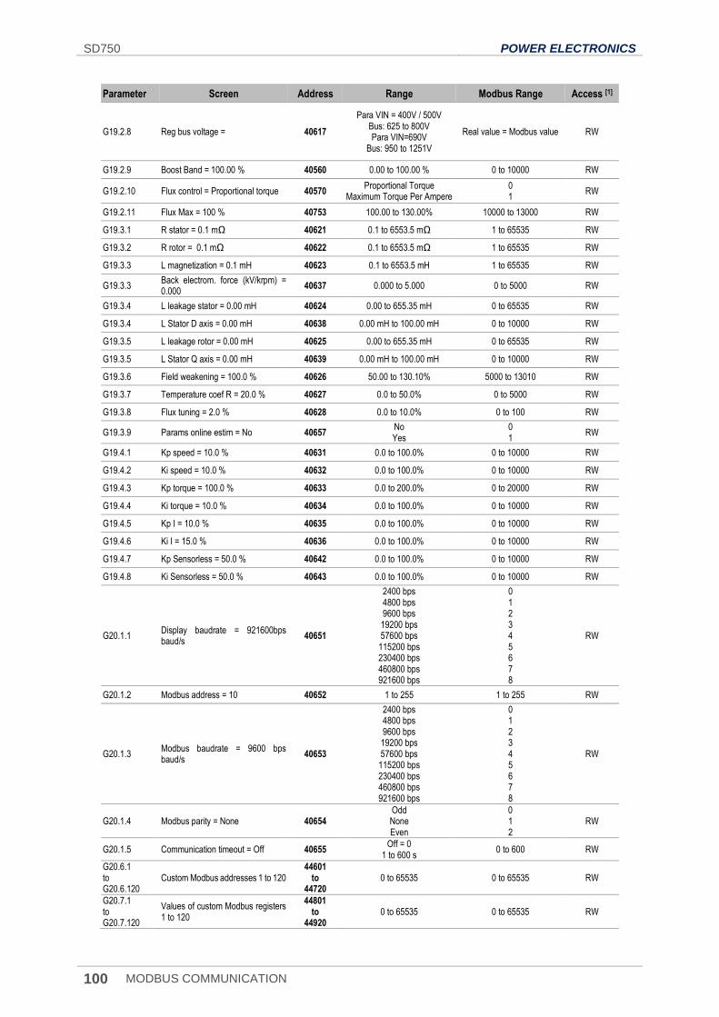
SD750 POWER ELECTRONICS
100 MODBUS COMMUNICATION
Parameter Screen Address Range Modbus Range Access [1]
G19.2.8 Reg bus voltage = 40617
Para VIN = 400V / 500V Bus: 625 to 800V Para VIN=690V
Bus: 950 to 1251V
Real value = Modbus value RW
G19.2.9 Boost Band = 100.00 % 40560 0.00 to 100.00 % 0 to 10000 RW
G19.2.10 Flux control = Proportional torque 40570 Proportional Torque
Maximum Torque Per Ampere 0 1
RW
G19.2.11 Flux Max = 100 % 40753 100.00 to 130.00% 10000 to 13000 RW
G19.3.1 R stator = 0.1 mΩ 40621 0.1 to 6553.5 mΩ 1 to 65535 RW
G19.3.2 R rotor = 0.1 mΩ 40622 0.1 to 6553.5 mΩ 1 to 65535 RW
G19.3.3 L magnetization = 0.1 mH 40623 0.1 to 6553.5 mH 1 to 65535 RW
G19.3.3 Back electrom. force (kV/krpm) = 0.000
40637 0.000 to 5.000 0 to 5000 RW
G19.3.4 L leakage stator = 0.00 mH 40624 0.00 to 655.35 mH 0 to 65535 RW
G19.3.4 L Stator D axis = 0.00 mH 40638 0.00 mH to 100.00 mH 0 to 10000 RW
G19.3.5 L leakage rotor = 0.00 mH 40625 0.00 to 655.35 mH 0 to 65535 RW
G19.3.5 L Stator Q axis = 0.00 mH 40639 0.00 mH to 100.00 mH 0 to 10000 RW
G19.3.6 Field weakening = 100.0 % 40626 50.00 to 130.10% 5000 to 13010 RW
G19.3.7 Temperature coef R = 20.0 % 40627 0.0 to 50.0% 0 to 5000 RW
G19.3.8 Flux tuning = 2.0 % 40628 0.0 to 10.0% 0 to 100 RW
G19.3.9 Params online estim = No 40657 No Yes
0 1
RW
G19.4.1 Kp speed = 10.0 % 40631 0.0 to 100.0% 0 to 10000 RW
G19.4.2 Ki speed = 10.0 % 40632 0.0 to 100.0% 0 to 10000 RW
G19.4.3 Kp torque = 100.0 % 40633 0.0 to 200.0% 0 to 20000 RW
G19.4.4 Ki torque = 10.0 % 40634 0.0 to 100.0% 0 to 10000 RW
G19.4.5 Kp I = 10.0 % 40635 0.0 to 100.0% 0 to 10000 RW
G19.4.6 Ki I = 15.0 % 40636 0.0 to 100.0% 0 to 10000 RW
G19.4.7 Kp Sensorless = 50.0 % 40642 0.0 to 100.0% 0 to 10000 RW
G19.4.8 Ki Sensorless = 50.0 % 40643 0.0 to 100.0% 0 to 10000 RW
G20.1.1 Display baudrate = 921600bps baud/s
40651
2400 bps 4800 bps 9600 bps 19200 bps 57600 bps 115200 bps 230400 bps 460800 bps 921600 bps
0 1 2 3 4 5 6 7 8
RW
G20.1.2 Modbus address = 10 40652 1 to 255 1 to 255 RW
G20.1.3 Modbus baudrate = 9600 bps baud/s
40653
2400 bps 4800 bps 9600 bps 19200 bps 57600 bps 115200 bps 230400 bps 460800 bps 921600 bps
0 1 2 3 4 5 6 7 8
RW
G20.1.4 Modbus parity = None 40654 Odd None Even
0 1 2
RW
G20.1.5 Communication timeout = Off 40655 Off = 0
1 to 600 s 0 to 600 RW
G20.6.1 to G20.6.120
Custom Modbus addresses 1 to 120 44601
to 44720
0 to 65535 0 to 65535 RW
G20.7.1 to G20.7.120
Values of custom Modbus registers 1 to 120
44801 to
44920 0 to 65535 0 to 65535 RW
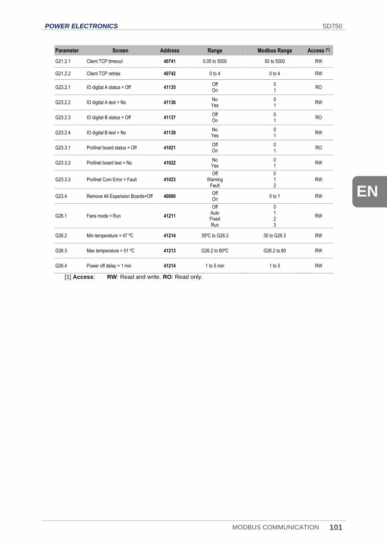
POWER ELECTRONICS SD750
MODBUS COMMUNICATION 101
EN
Parameter Screen Address Range Modbus Range Access [1]
G21.2.1 Client TCP timeout 40741 0.05 to 5000 50 to 5000 RW
G21.2.2 Client TCP retries 40742 0 to 4 0 to 4 RW
G23.2.1 IO digital A status = Off 41135 Off On
0 1
RO
G23.2.2 IO digital A test = No 41136 No Yes
0 1
RW
G23.2.3 IO digital B status = Off 41137 Off On
0 1
RO
G23.2.4 IO digital B test = No 41138 No Yes
0 1
RW
G23.3.1 Profinet board status = Off 41021 Off On
0 1
RO
G23.3.2 Profinet board test = No 41022 No Yes
0 1
RW
G23.3.3 Profinet Com Error = Fault 41023 Off
Warning Fault
0 1 2
RW
G23.4 Remove All Expansion Boards=Off 40880 Off On
0 to 1 RW
G26.1 Fans mode = Run 41211
Off Auto Fixed Run
0 1 2 3
RW
G26.2 Min temperature = 47 ºC 41214 35ºC to G26.3 35 to G26.3 RW
G26.3 Max temperature = 51 ºC 41213 G26.2 to 80ºC G26.2 to 80 RW
G26.4 Power off delay = 1 min 41214 1 to 5 min 1 to 5 RW
[1] Access: RW: Read and write. RO: Read only.
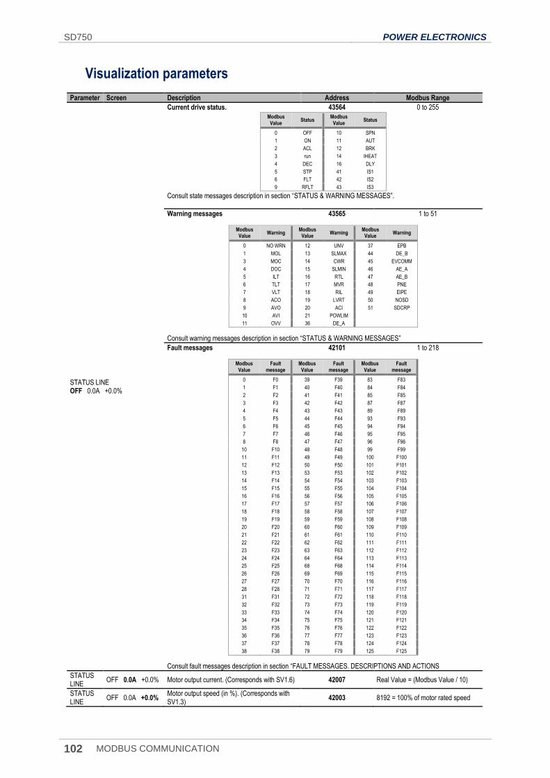
SD750 POWER ELECTRONICS
102 MODBUS COMMUNICATION
Visualization parameters
Parameter Screen Description Address Modbus Range
STATUS LINE OFF 0.0A +0.0%
Current drive status. 43564 0 to 255
Modbus Value
Status Modbus
Value Status
0 OFF 10 SPN
1 ON 11 AUT
2 ACL 12 BRK
3 run 14 IHEAT
4 DEC 16 DLY
5 STP 41 IS1
6 FLT 42 IS2
9 RFLT 43 IS3
Consult state messages description in section “STATUS & WARNING MESSAGES”.
Warning messages 43565 1 to 51
Modbus Value
Warning Modbus
Value Warning
Modbus Value
Warning
0 NO WRN 12 UNV 37 EPB
1 MOL 13 SLMAX 44 DE_B
3 MOC 14 CWR 45 EVCOMM
4 DOC 15 SLMIN 46 AE_A
5 ILT 16 RTL 47 AE_B
6 TLT 17 MVR 48 PNE
7 VLT 18 RIL 49 EIPE
8 ACO 19 LVRT 50 NOSD
9 AVO 20 ACI 51 SDCRP
10 AVI 21 POWLIM
11 OVV 36 DE_A
Consult warning messages description in section “STATUS & WARNING MESSAGES”
Fault messages 42101 1 to 218
Modbus Value
Fault message
Modbus Value
Fault message
Modbus Value
Fault message
0 F0 39 F39 83 F83
1 F1 40 F40 84 F84
2 F2 41 F41 85 F85
3 F3 42 F42 87 F87
4 F4 43 F43 89 F89
5 F5 44 F44 93 F93
6 F6 45 F45 94 F94
7 F7 46 F46 95 F95
8 F8 47 F47 96 F96
10 F10 48 F48 99 F99
11 F11 49 F49 100 F100
12 F12 50 F50 101 F101
13 F13 53 F53 102 F102
14 F14 54 F54 103 F103
15 F15 55 F55 104 F104
16 F16 56 F56 105 F105
17 F17 57 F57 106 F106
18 F18 58 F58 107 F107
19 F19 59 F59 108 F108
20 F20 60 F60 109 F109
21 F21 61 F61 110 F110
22 F22 62 F62 111 F111
23 F23 63 F63 112 F112
24 F24 64 F64 113 F113
25 F25 68 F68 114 F114
26 F26 69 F69 115 F115
27 F27 70 F70 116 F116
28 F28 71 F71 117 F117
31 F31 72 F72 118 F118
32 F32 73 F73 119 F119
33 F33 74 F74 120 F120
34 F34 75 F75 121 F121
35 F35 76 F76 122 F122
36 F36 77 F77 123 F123
37 F37 78 F78 124 F124
38 F38 79 F79 125 F125
Consult fault messages description in section “FAULT MESSAGES. DESCRIPTIONS AND ACTIONS
STATUS LINE
OFF 0.0A +0.0% Motor output current. (Corresponds with SV1.6) 42007 Real Value = (Modbus Value / 10)
STATUS LINE
OFF 0.0A +0.0% Motor output speed (in %). (Corresponds with SV1.3)
42003 8192 = 100% of motor rated speed

POWER ELECTRONICS SD750
MODBUS COMMUNICATION 103
EN
Parameter Screen Description Address Modbus Range
SV1.1 Speed reference = 0.0 % Shows the present reference value of speed which is applied to the motor.
42001 Real Value = (Modbus Value / 100)
SV1.2 Torque reference = 0.0 % Shows the present reference value of torque which is applied to the motor.
42002 Real Value = (Modbus Value / 100)
SV1.3 Motor speed (%) = 0.0 % Shows the motor speed in percentage. 42003 Real Value = (Modbus Value / 100)
SV1.4 Motor speed (rpm) = 0 rpm Shows the motor speed in revolutions per minute.
42004 Real Value = Modbus Value
SV1.5 Motor frequency = 0.0 Hz Shows the frequency being applied to the motor.
42005 Real Value = (Modbus Value / 10)
SV1.6 Motor voltage = 0 V Shows the present voltage applied to the motor.
42006 Real Value = Modbus Value
SV1.7 Motor current = 0.0 A Shows the present current flowing to the motor.
42007 Real Value = (Modbus Value / 10)
SV1.8 Motor torque = 0.0 % Shows the present torque applied to the motor.
42008 Real Value = (Modbus Value / 100)
SV1.9 Motor phi cosine = 0.85 Shows the motor's cos phi. 42009 Real Value = (Modbus Value / 100)
SV1.10 Motor power = 0.0 kW Shows the instantaneous power consumption of the motor.
42010 Real Value = Modbus Value
SV1.11.1 U motor current = 0.0 A
Shows the instantaneous current of each phase of the motor (U, V and W).
42011 Real Value = (Modbus Value / 10)
SV1.11.2 V motor current = 0.0 A 42012 Real Value = (Modbus Value / 10)
SV1.11.3 W motor current = 0.0 A 42013 Real Value = (Modbus Value / 10)
SV1.12.1 U-V motor voltage = 0 V
Shows the instantaneous voltage applied (UV, VW, UW).
42014 Real Value = Modbus Value
SV1.12.2 V-W motor voltage = 0 V 42015 Real Value = Modbus Value
SV1.12.3 W-U motor voltage = 0 V 42016 Real Value = Modbus Value
SV1.13 PTC Status = No Shows whether the motor PTC is connected or disconnected.
42017 Real Value = Modbus Value
SV1.14 Estimat. Motor temp(%) = 0.0 % Shows the estimated motor temperature. 42018 Real Value = (Modbus Value / 100)
SV1.15 Motor temperature = 0 ºC Shows the motor temperature. 42019 Real Value = Modbus Value
SV2.1.1 L1-L2 supply voltage = 0 V
Shows the input instantaneous voltage applied to the drive (RS, ST and TR).
42031 Real Value = Modbus Value
SV2.1.2 L2-L3 supply voltage = 0 V 42032 Real Value = Modbus Value
SV2.1.3 L3-L1 supply voltage = 0 V 42033 Real Value = Modbus Value
SV2.2 Input voltage average = 0 V Shows the average input voltage to the drive.
42034 Real Value = Modbus Value
SV2.3 DC bus voltage = 0 V Shows DC Link voltage of the drive. 42035 Real Value = Modbus Value
SV2.4 Input frequency = 0.0 Hz Shows the frequency of the drive input voltage
42036 Real Value = (Modbus Value / 10)
SV2.5.1 Drive temperature = 0 ºC Shows the temperature measured inside the electronics chamber of the drive.
42039 Real Value = Modbus Value
SV2.5.2 IGBT temperature = 0 ºC Shows the maximum temperature measured at the power stage
42040 Real Value = Modbus Value
SV2.10 Relative Humidity = 0 % Shows the internal relative humidity of the converter.
42050 Real Value = Modbus Value
SV3.1 AI1 value = 0.00 V Shows the value of Analogue Input 1. 42061 Real Value = (Modbus Value / 1000)
SV3.2 AI1 percentage = 100.0 % Shows the value or the PID reference proportional to Analogue Input 1
42062 Real Value = (Modbus Value / 100)
SV3.3 AI1 sensor value = 0.0 l/s Value of sensor 1 associated to AI1. 42063 Real Value = (Modbus Value / 10)
SV3.4 AI2 value = 0.00 mA Shows the value of the Analogue Input 2. 42064 Real Value = (Modbus Value / 1000)
SV3.5 AI2 percentage = 100.0 % Value or the PID reference proportional to the AI 2 signal.
42065 Real Value = (Modbus Value / 100)
SV3.6 AI2 sensor value = 0.0 Bar Value of sensor 2 associated to the AI2. 42066 Real Value = (Modbus Value / 10)
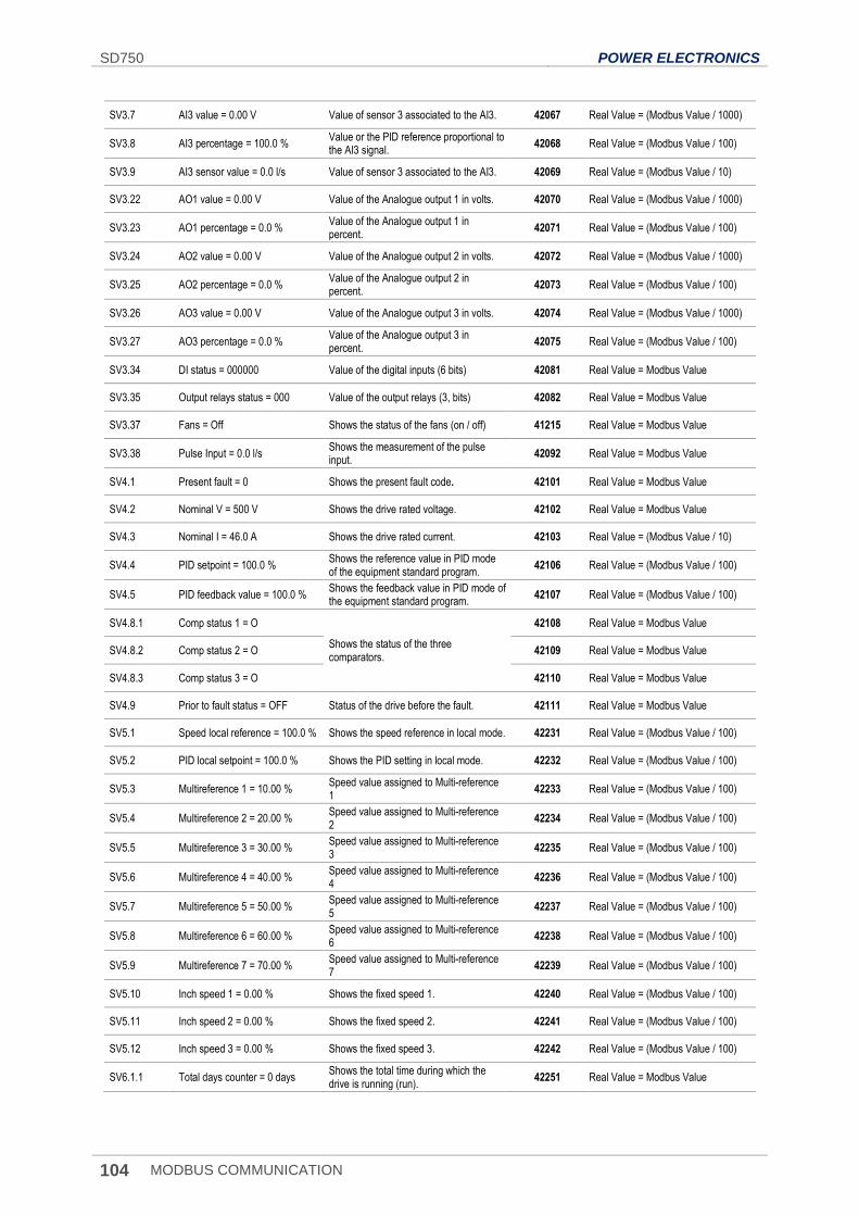
SD750 POWER ELECTRONICS
104 MODBUS COMMUNICATION
SV3.7 AI3 value = 0.00 V Value of sensor 3 associated to the AI3. 42067 Real Value = (Modbus Value / 1000)
SV3.8 AI3 percentage = 100.0 % Value or the PID reference proportional to the AI3 signal.
42068 Real Value = (Modbus Value / 100)
SV3.9 AI3 sensor value = 0.0 l/s Value of sensor 3 associated to the AI3. 42069 Real Value = (Modbus Value / 10)
SV3.22 AO1 value = 0.00 V Value of the Analogue output 1 in volts. 42070 Real Value = (Modbus Value / 1000)
SV3.23 AO1 percentage = 0.0 % Value of the Analogue output 1 in percent.
42071 Real Value = (Modbus Value / 100)
SV3.24 AO2 value = 0.00 V Value of the Analogue output 2 in volts. 42072 Real Value = (Modbus Value / 1000)
SV3.25 AO2 percentage = 0.0 % Value of the Analogue output 2 in percent.
42073 Real Value = (Modbus Value / 100)
SV3.26 AO3 value = 0.00 V Value of the Analogue output 3 in volts. 42074 Real Value = (Modbus Value / 1000)
SV3.27 AO3 percentage = 0.0 % Value of the Analogue output 3 in percent.
42075 Real Value = (Modbus Value / 100)
SV3.34 DI status = 000000 Value of the digital inputs (6 bits) 42081 Real Value = Modbus Value
SV3.35 Output relays status = 000 Value of the output relays (3, bits) 42082 Real Value = Modbus Value
SV3.37 Fans = Off Shows the status of the fans (on / off) 41215 Real Value = Modbus Value
SV3.38 Pulse Input = 0.0 l/s Shows the measurement of the pulse input.
42092 Real Value = Modbus Value
SV4.1 Present fault = 0 Shows the present fault code. 42101 Real Value = Modbus Value
SV4.2 Nominal V = 500 V Shows the drive rated voltage. 42102 Real Value = Modbus Value
SV4.3 Nominal I = 46.0 A Shows the drive rated current. 42103 Real Value = (Modbus Value / 10)
SV4.4 PID setpoint = 100.0 % Shows the reference value in PID mode of the equipment standard program.
42106 Real Value = (Modbus Value / 100)
SV4.5 PID feedback value = 100.0 % Shows the feedback value in PID mode of the equipment standard program.
42107 Real Value = (Modbus Value / 100)
SV4.8.1 Comp status 1 = O
Shows the status of the three comparators.
42108 Real Value = Modbus Value
SV4.8.2 Comp status 2 = O 42109 Real Value = Modbus Value
SV4.8.3 Comp status 3 = O 42110 Real Value = Modbus Value
SV4.9 Prior to fault status = OFF Status of the drive before the fault. 42111 Real Value = Modbus Value
SV5.1 Speed local reference = 100.0 % Shows the speed reference in local mode. 42231 Real Value = (Modbus Value / 100)
SV5.2 PID local setpoint = 100.0 % Shows the PID setting in local mode. 42232 Real Value = (Modbus Value / 100)
SV5.3 Multireference 1 = 10.00 % Speed value assigned to Multi-reference 1
42233 Real Value = (Modbus Value / 100)
SV5.4 Multireference 2 = 20.00 % Speed value assigned to Multi-reference 2
42234 Real Value = (Modbus Value / 100)
SV5.5 Multireference 3 = 30.00 % Speed value assigned to Multi-reference 3
42235 Real Value = (Modbus Value / 100)
SV5.6 Multireference 4 = 40.00 % Speed value assigned to Multi-reference 4
42236 Real Value = (Modbus Value / 100)
SV5.7 Multireference 5 = 50.00 % Speed value assigned to Multi-reference 5
42237 Real Value = (Modbus Value / 100)
SV5.8 Multireference 6 = 60.00 % Speed value assigned to Multi-reference 6
42238 Real Value = (Modbus Value / 100)
SV5.9 Multireference 7 = 70.00 % Speed value assigned to Multi-reference 7
42239 Real Value = (Modbus Value / 100)
SV5.10 Inch speed 1 = 0.00 % Shows the fixed speed 1. 42240 Real Value = (Modbus Value / 100)
SV5.11 Inch speed 2 = 0.00 % Shows the fixed speed 2. 42241 Real Value = (Modbus Value / 100)
SV5.12 Inch speed 3 = 0.00 % Shows the fixed speed 3. 42242 Real Value = (Modbus Value / 100)
SV6.1.1 Total days counter = 0 days Shows the total time during which the drive is running (run).
42251 Real Value = Modbus Value
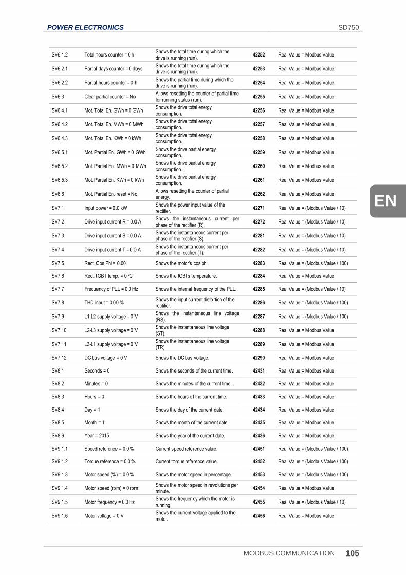
POWER ELECTRONICS SD750
MODBUS COMMUNICATION 105
EN
SV6.1.2 Total hours counter = 0 h Shows the total time during which the drive is running (run).
42252 Real Value = Modbus Value
SV6.2.1 Partial days counter = 0 days Shows the total time during which the drive is running (run).
42253 Real Value = Modbus Value
SV6.2.2 Partial hours counter = 0 h Shows the partial time during which the drive is running (run).
42254 Real Value = Modbus Value
SV6.3 Clear partial counter = No Allows resetting the counter of partial time for running status (run).
42255 Real Value = Modbus Value
SV6.4.1 Mot. Total En. GWh = 0 GWh Shows the drive total energy consumption.
42256 Real Value = Modbus Value
SV6.4.2 Mot. Total En. MWh = 0 MWh Shows the drive total energy consumption.
42257 Real Value = Modbus Value
SV6.4.3 Mot. Total En. KWh = 0 kWh Shows the drive total energy consumption.
42258 Real Value = Modbus Value
SV6.5.1 Mot. Partial En. GWh = 0 GWh Shows the drive partial energy consumption.
42259 Real Value = Modbus Value
SV6.5.2 Mot. Partial En. MWh = 0 MWh Shows the drive partial energy consumption.
42260 Real Value = Modbus Value
SV6.5.3 Mot. Partial En. KWh = 0 kWh Shows the drive partial energy consumption.
42261 Real Value = Modbus Value
SV6.6 Mot. Partial En. reset = No Allows resetting the counter of partial energy.
42262 Real Value = Modbus Value
SV7.1 Input power = 0.0 kW Shows the power input value of the rectifier.
42271 Real Value = (Modbus Value / 10)
SV7.2 Drive input current R = 0.0 A Shows the instantaneous current per phase of the rectifier (R).
42272 Real Value = (Modbus Value / 10)
SV7.3 Drive input current S = 0.0 A Shows the instantaneous current per phase of the rectifier (S).
42281 Real Value = (Modbus Value / 10)
SV7.4 Drive input current T = 0.0 A Shows the instantaneous current per phase of the rectifier (T).
42282 Real Value = (Modbus Value / 10)
SV7.5 Rect. Cos Phi = 0.00 Shows the motor's cos phi. 42283 Real Value = (Modbus Value / 100)
SV7.6 Rect. IGBT temp. = 0 ºC Shows the IGBTs temperature. 42284 Real Value = Modbus Value
SV7.7 Frequency of PLL = 0.0 Hz Shows the internal frequency of the PLL. 42285 Real Value = (Modbus Value / 10)
SV7.8 THD input = 0.00 % Shows the input current distortion of the rectifier.
42286 Real Value = (Modbus Value / 100)
SV7.9 L1-L2 supply voltage = 0 V Shows the instantaneous line voltage (RS).
42287 Real Value = (Modbus Value / 100)
SV7.10 L2-L3 supply voltage = 0 V Shows the instantaneous line voltage (ST).
42288 Real Value = Modbus Value
SV7.11 L3-L1 supply voltage = 0 V Shows the instantaneous line voltage (TR).
42289 Real Value = Modbus Value
SV7.12 DC bus voltage = 0 V Shows the DC bus voltage. 42290 Real Value = Modbus Value
SV8.1 Seconds = 0 Shows the seconds of the current time. 42431 Real Value = Modbus Value
SV8.2 Minutes = 0 Shows the minutes of the current time. 42432 Real Value = Modbus Value
SV8.3 Hours = 0 Shows the hours of the current time. 42433 Real Value = Modbus Value
SV8.4 Day = 1 Shows the day of the current date. 42434 Real Value = Modbus Value
SV8.5 Month = 1 Shows the month of the current date. 42435 Real Value = Modbus Value
SV8.6 Year = 2015 Shows the year of the current date. 42436 Real Value = Modbus Value
SV9.1.1 Speed reference = 0.0 % Current speed reference value. 42451 Real Value = (Modbus Value / 100)
SV9.1.2 Torque reference = 0.0 % Current torque reference value. 42452 Real Value = (Modbus Value / 100)
SV9.1.3 Motor speed (%) = 0.0 % Shows the motor speed in percentage. 42453 Real Value = (Modbus Value / 100)
SV9.1.4 Motor speed (rpm) = 0 rpm Shows the motor speed in revolutions per minute.
42454 Real Value = Modbus Value
SV9.1.5 Motor frequency = 0.0 Hz Shows the frequency which the motor is running.
42455 Real Value = (Modbus Value / 10)
SV9.1.6 Motor voltage = 0 V Shows the current voltage applied to the motor.
42456 Real Value = Modbus Value
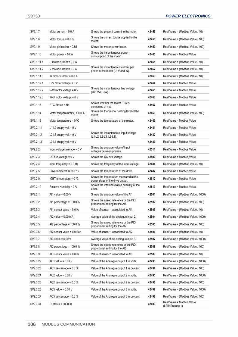
SD750 POWER ELECTRONICS
106 MODBUS COMMUNICATION
SV9.1.7 Motor current = 0.0 A Shows the present current to the motor. 42457 Real Value = (Modbus Value / 10)
SV9.1.8 Motor torque = 0.0 % Shows the current torque applied to the motor.
42458 Real Value = (Modbus Value / 100)
SV9.1.9 Motor phi cosine = 0.85 Shows the motor power factor. 42459 Real Value = (Modbus Value / 100)
SV9.1.10 Motor power = 0 kW Shows the instantaneous power consumption of the motor.
42460 Real Value = Modbus Value
SV9.1.11.1 U motor current = 0.0 A
Shows the instantaneous current per phase of the motor (U, V and W).
42461 Real Value = (Modbus Value / 10)
SV9.1.11.2 V motor current = 0.0 A 42462 Real Value = (Modbus Value / 10)
SV9.1.11.3 W motor current = 0.0 A 42463 Real Value = (Modbus Value / 10)
SV9.1.12.1 U-V motor voltage = 0 V
Shows the instantaneous line voltage (UV, VW, UW).
42464 Real Value = Modbus Value
SV9.1.12.2 V-W motor voltage = 0 V 42465 Real Value = Modbus Value
SV9.1.12.3 W-U motor voltage = 0 V 42466 Real Value = Modbus Value
SV9.1.13 PTC Status = No Shows whether the motor PTC is connected or not.
42467 Real Value = Modbus Value
SV9.1.14 Motor temperature(%) = 0.0 % Shows the theoretical heating level of the motor.
42468 Real Value = (Modbus Value / 100)
SV9.1.15 Motor temperature = 0 ºC Shows the temperature of the motor. 42469 Real Value = Modbus Value
SV9.2.1.1 L1-L2 supply volt = 0 V
Shows the instantaneous input voltage (L1-L2, L2-L3, L3-L1).
42481 Real Value = Modbus Value
SV9.2.1.2 L2-L3 supply volt = 0 V 42482 Real Value = Modbus Value
SV9.2.1.3 L3-L1 supply volt = 0 V 42483 Real Value = Modbus Value
SV9.2.2 Input voltage average = 0 V Shows the average value of input voltages between phases.
42511 Real Value = Modbus Value
SV9.2.3 DC bus voltage = 0 V Shows the DC bus voltage. 42500 Real Value = Modbus Value
SV9.2.4 Input frequency = 0.0 Hz Shows the frequency of the input voltage. 42484 Real Value = (Modbus Value / 10)
SV9.2.5 Drive temperature = 0 ºC Shows the temperature of the drive. 42487 Real Value = Modbus Value
SV9.2.9 IGBT temperature = 0 ºC Shows the temperature measured at the power stage of the drive output.
42512 Real Value = Modbus Value
SV9.2.10 Relative Humidity = 0 % Shows the internal relative humidity of the drive.
42513 Real Value = Modbus Value
SV9.3.1 AI1 value = 0.00 V Shows the average value of the AI1. 42501 Real Value = (Modbus Value / 1000)
SV9.3.2 AI1 percentage = 100.0 % Shows the speed reference or the PID proportional setting for the AI1.
42502 Real Value = (Modbus Value / 100)
SV9.3.3 AI1 sensor value = 0.0 l/s Value of sensor 1 associated to AI1. 42503 Real Value = (Modbus Value / 10)
SV9.3.4 AI2 value = 0.00 mA Average value of the analogue input 2. 42504 Real Value = (Modbus Value / 1000)
SV9.3.5 AI2 percentage = 100.0 % Shows the speed reference or the PID proportional setting for the AI2.
42505 Real Value = (Modbus Value / 100)
SV9.3.6 AI2 sensor value = 0.0 Bar Value of sensor 1 associated to AI2. 42506 Real Value = (Modbus Value / 10)
SV9.3.7 AI3 value = 0.00 V Average value of the analogue input 3. 42507 Real Value = (Modbus Value / 1000)
SV9.3.8 AI3 percentage = 100.0 % Shows the speed reference or the PID proportional setting for the AI3.
42508 Real Value = (Modbus Value / 100)
SV9.3.9 AI3 sensor value = 0.0 l/s Value of sensor 1 associated to AI3. 42509 Real Value = (Modbus Value / 10)
SV9.3.22 AO1 value = 0.00 V Value of the Analogue output 1 in volts. 42493 Real Value = (Modbus Value / 1000)
SV9.3.23 AO1 percentage = 0.0 % Value of the Analogue output 1 in percent. 42494 Real Value = (Modbus Value / 100)
SV9.3.24 AO2 value = 0.00 V Value of the Analogue output 2 in volts. 42495 Real Value = (Modbus Value / 1000)
SV9.3.25 AO2 percentage = 0.0 % Value of the Analogue output 2 in percent. 42496 Real Value = (Modbus Value / 100)
SV9.3.26 AO3 value = 0.00 V Value of the Analogue output 3 in volts. 42497 Real Value = (Modbus Value / 1000)
SV9.3.27 AO3 percentage = 0.0 % Value of the Analogue output 3 in percent. 42498 Real Value = (Modbus Value / 100)
SV9.3.34 DI status = 000000 42499 Real Value = Modbus Value (LSB: Entrada 1)
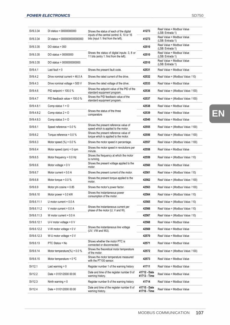
POWER ELECTRONICS SD750
MODBUS COMMUNICATION 107
EN
SV9.3.34 DI status = 00000000000 Shows the status of each of the digital inputs of the central control: 6, 10 or 16 bits (input 1: first from the left).
41273 Real Value = Modbus Value (LSB: Entrada 1)
SV9.3.34 DI status = 0000000000000000 41273 Real Value = Modbus Value (LSB: Entrada 1)
SV9.3.35 DO status = 000
Shows the status of digital inputs: 3, 8 or 11 bits (entry 1: first from the left).
42510 Real Value = Modbus Value (LSB: Entrada 1)
SV9.3.35 DO status = 00000000 42510 Real Value = Modbus Value (LSB: Entrada 1)
SV9.3.35 DO status = 0000000000000 42510 Real Value = Modbus Value (LSB: Entrada 1)
SV9.4.1 Last fault = 0 Shows the present fault code. 42531 Real Value = Modbus Value
SV9.4.2 Drive nominal current = 46.0 A Shows the rated current of the drive. 42532 Real Value = (Modbus Value / 10)
SV9.4.3 Drive nominal voltage = 500 V Shows the rated voltage of the drive. 42533 Real Value = Modbus Value
SV9.4.6 PID setpoint = 100.0 % Shows the setpoint value of the PID of the standard equipment program.
42536 Real Value = (Modbus Value / 100)
SV9.4.7 PID feedback value = 100.0 % Shows the PID feedback value of the standard equipment program.
42537 Real Value = (Modbus Value / 100)
SV9.4.8.1 Comp status 1 = O
Shows the status of the three comparators
42538 Real Value = Modbus Value
SV9.4.8.2 Comp status 2 = O 42539 Real Value = Modbus Value
SV9.4.8.3 Comp status 3 = O 42540 Real Value = Modbus Value
SV9.6.1 Speed reference = 0.0 % Shows the present reference value of speed which is applied to the motor.
42555 Real Value = (Modbus Value / 100)
SV9.6.2 Torque reference = 0.0 % Shows the present reference value of torque which is applied to the motor.
42556 Real Value = (Modbus Value / 100)
SV9.6.3 Motor speed (%) = 0.0 % Shows the motor speed in percentage. 42557 Real Value = (Modbus Value / 100)
SV9.6.4 Motor speed (rpm) = 0 rpm Shows the motor speed in revolutions per minute.
42558 Real Value = Modbus Value
SV9.6.5 Motor frequency = 0.0 Hz Shows the frequency at which the motor is running.
42559 Real Value = (Modbus Value / 10)
SV9.6.6 Motor voltage = 0 V Shows the present voltage applied to the motor.
42560 Real Value = Modbus Value
SV9.6.7 Motor current = 0.0 A Shows the present current of the motor. 42561 Real Value = (Modbus Value / 10)
SV9.6.8 Motor torque = 0.0 % Shows the present torque applied to the motor.
42562 Real Value = (Modbus Value / 100)
SV9.6.9 Motor phi cosine = 0.85 Shows the motor’s power factor. 42563 Real Value = (Modbus Value / 100)
SV9.6.10 Motor power = 0.0 kW Shows the instantaneous power consumption of the motor.
42564 Real Value = (Modbus Value / 10)
SV9.6.11.1 U motor current = 0.0 A
Shows the instantaneous current per phase of the motor (U, V and W).
42565 Real Value = (Modbus Value / 10)
SV9.6.11.2 V motor current = 0.0 A 42566 Real Value = (Modbus Value / 10)
SV9.6.11.3 W motor current = 0.0 A 42567 Real Value = (Modbus Value / 10)
SV9.6.12.1 U-V motor voltage = 0 V
Shows the instantaneous line voltage (UV, VW and WU).
42568 Real Value = Modbus Value
SV9.6.12.2 V-W motor voltage = 0 V 42569 Real Value = Modbus Value
SV9.6.12.3 W-U motor voltage = 0 V 42570 Real Value = Modbus Value
SV9.6.13 PTC Status = No Shows whether the motor PTC is connected or disconnected.
42571 Real Value = Modbus Value
SV9.6.14 Motor temperature(%) = 0.0 % Shows the theoretical motor temperature of the motor.
42572 Real Value = (Modbus Value / 100)
SV9.6.15 Motor temperature = 0 ºC Shows the motor temperature measured with the PT100 sensor.
42573 Real Value = Modbus Value
SV12.1 Last warning = 0 Register number 1 of the warning history 41711 Real Value = Modbus Value
SV12.2 Date = 01/01/2000 00:00 Date and time of the register number 9 of warning history.
41712 - Date 41713 - Time
Real Value = Modbus Value
SV12.3 Ninth warning = 0 Register number 9 of the warning history 41714 Real Value = Modbus Value
SV12.4 Date = 01/01/2000 00:00 Date and time of the register number 8 of warning history.
41715 - Date 41716 - Time
Real Value = Modbus Value
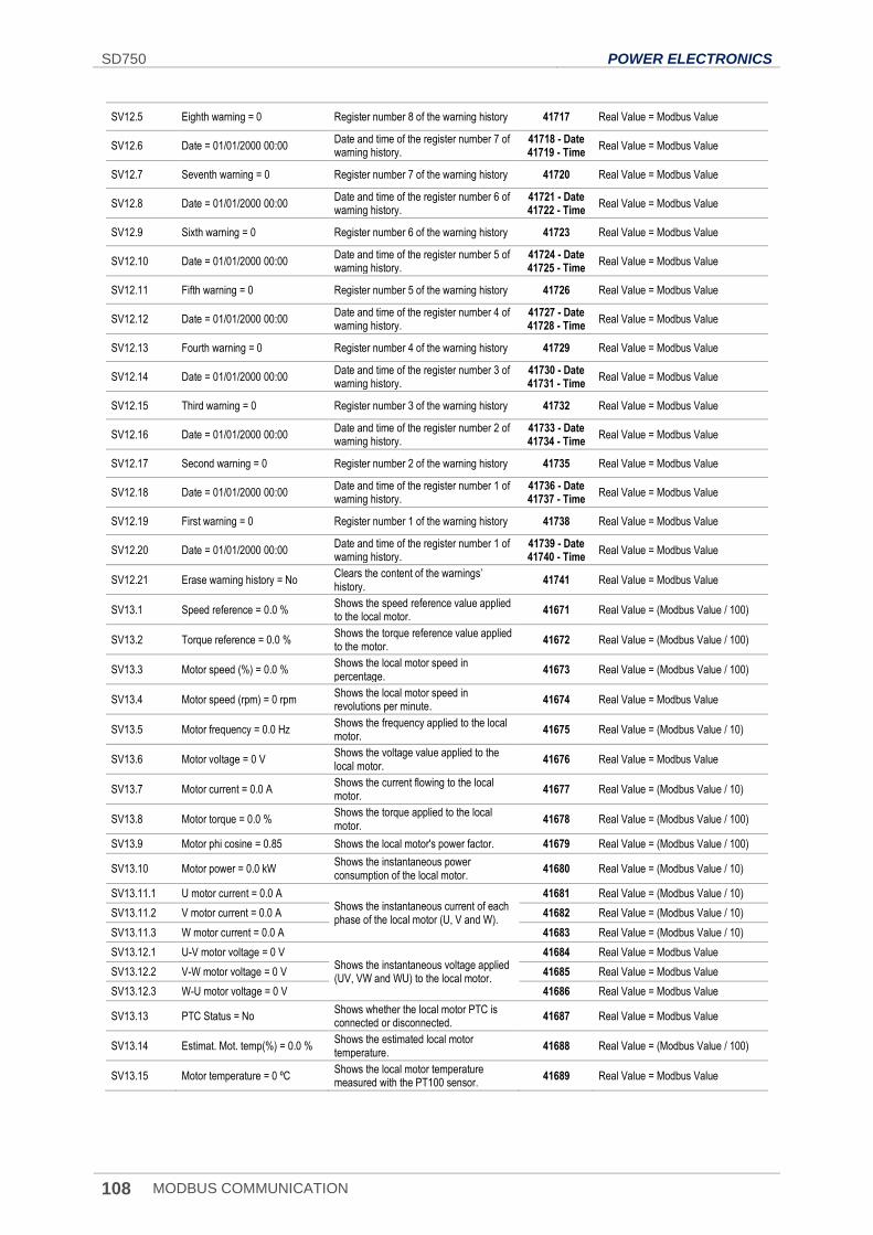
SD750 POWER ELECTRONICS
108 MODBUS COMMUNICATION
SV12.5 Eighth warning = 0 Register number 8 of the warning history 41717 Real Value = Modbus Value
SV12.6 Date = 01/01/2000 00:00 Date and time of the register number 7 of warning history.
41718 - Date 41719 - Time
Real Value = Modbus Value
SV12.7 Seventh warning = 0 Register number 7 of the warning history 41720 Real Value = Modbus Value
SV12.8 Date = 01/01/2000 00:00 Date and time of the register number 6 of warning history.
41721 - Date 41722 - Time
Real Value = Modbus Value
SV12.9 Sixth warning = 0 Register number 6 of the warning history 41723 Real Value = Modbus Value
SV12.10 Date = 01/01/2000 00:00 Date and time of the register number 5 of warning history.
41724 - Date 41725 - Time
Real Value = Modbus Value
SV12.11 Fifth warning = 0 Register number 5 of the warning history 41726 Real Value = Modbus Value
SV12.12 Date = 01/01/2000 00:00 Date and time of the register number 4 of warning history.
41727 - Date 41728 - Time
Real Value = Modbus Value
SV12.13 Fourth warning = 0 Register number 4 of the warning history 41729 Real Value = Modbus Value
SV12.14 Date = 01/01/2000 00:00 Date and time of the register number 3 of warning history.
41730 - Date 41731 - Time
Real Value = Modbus Value
SV12.15 Third warning = 0 Register number 3 of the warning history 41732 Real Value = Modbus Value
SV12.16 Date = 01/01/2000 00:00 Date and time of the register number 2 of warning history.
41733 - Date 41734 - Time
Real Value = Modbus Value
SV12.17 Second warning = 0 Register number 2 of the warning history 41735 Real Value = Modbus Value
SV12.18 Date = 01/01/2000 00:00 Date and time of the register number 1 of warning history.
41736 - Date 41737 - Time
Real Value = Modbus Value
SV12.19 First warning = 0 Register number 1 of the warning history 41738 Real Value = Modbus Value
SV12.20 Date = 01/01/2000 00:00 Date and time of the register number 1 of warning history.
41739 - Date 41740 - Time
Real Value = Modbus Value
SV12.21 Erase warning history = No Clears the content of the warnings’ history.
41741 Real Value = Modbus Value
SV13.1 Speed reference = 0.0 % Shows the speed reference value applied to the local motor.
41671 Real Value = (Modbus Value / 100)
SV13.2 Torque reference = 0.0 % Shows the torque reference value applied to the motor.
41672 Real Value = (Modbus Value / 100)
SV13.3 Motor speed (%) = 0.0 % Shows the local motor speed in percentage.
41673 Real Value = (Modbus Value / 100)
SV13.4 Motor speed (rpm) = 0 rpm Shows the local motor speed in revolutions per minute.
41674 Real Value = Modbus Value
SV13.5 Motor frequency = 0.0 Hz Shows the frequency applied to the local motor.
41675 Real Value = (Modbus Value / 10)
SV13.6 Motor voltage = 0 V Shows the voltage value applied to the local motor.
41676 Real Value = Modbus Value
SV13.7 Motor current = 0.0 A Shows the current flowing to the local motor.
41677 Real Value = (Modbus Value / 10)
SV13.8 Motor torque = 0.0 % Shows the torque applied to the local motor.
41678 Real Value = (Modbus Value / 100)
SV13.9 Motor phi cosine = 0.85 Shows the local motor's power factor. 41679 Real Value = (Modbus Value / 100)
SV13.10 Motor power = 0.0 kW Shows the instantaneous power consumption of the local motor.
41680 Real Value = (Modbus Value / 10)
SV13.11.1 U motor current = 0.0 A Shows the instantaneous current of each phase of the local motor (U, V and W).
41681 Real Value = (Modbus Value / 10)
SV13.11.2 V motor current = 0.0 A 41682 Real Value = (Modbus Value / 10)
SV13.11.3 W motor current = 0.0 A 41683 Real Value = (Modbus Value / 10)
SV13.12.1 U-V motor voltage = 0 V Shows the instantaneous voltage applied (UV, VW and WU) to the local motor.
41684 Real Value = Modbus Value
SV13.12.2 V-W motor voltage = 0 V 41685 Real Value = Modbus Value
SV13.12.3 W-U motor voltage = 0 V 41686 Real Value = Modbus Value
SV13.13 PTC Status = No Shows whether the local motor PTC is connected or disconnected.
41687 Real Value = Modbus Value
SV13.14 Estimat. Mot. temp(%) = 0.0 % Shows the estimated local motor temperature.
41688 Real Value = (Modbus Value / 100)
SV13.15 Motor temperature = 0 ºC Shows the local motor temperature measured with the PT100 sensor.
41689 Real Value = Modbus Value
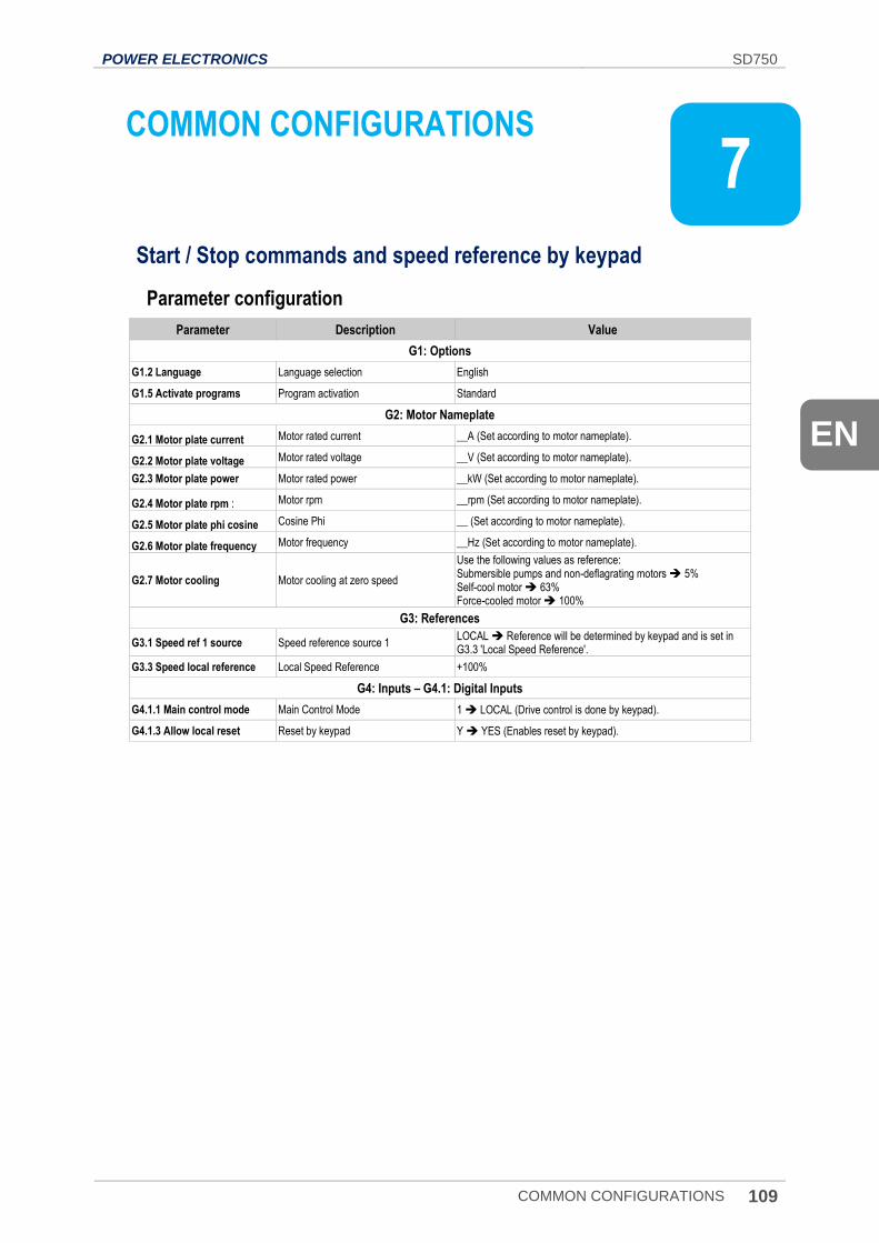
POWER ELECTRONICS SD750
COMMON CONFIGURATIONS 109
EN
7. COMMON CONFIGURATIONS
Start / Stop commands and speed reference by keypad
Parameter configuration
Parameter Description Value
G1: Options
G1.2 Language Language selection English
G1.5 Activate programs Program activation Standard
G2: Motor Nameplate
G2.1 Motor plate current Motor rated current __A (Set according to motor nameplate).
G2.2 Motor plate voltage Motor rated voltage __V (Set according to motor nameplate).
G2.3 Motor plate power Motor rated power __kW (Set according to motor nameplate).
G2.4 Motor plate rpm : Motor rpm __rpm (Set according to motor nameplate).
G2.5 Motor plate phi cosine Cosine Phi __ (Set according to motor nameplate).
G2.6 Motor plate frequency Motor frequency __Hz (Set according to motor nameplate).
G2.7 Motor cooling Motor cooling at zero speed
Use the following values as reference: Submersible pumps and non-deflagrating motors 5% Self-cool motor 63% Force-cooled motor 100%
G3: References
G3.1 Speed ref 1 source Speed reference source 1 LOCAL Reference will be determined by keypad and is set in G3.3 'Local Speed Reference'.
G3.3 Speed local reference Local Speed Reference +100%
G4: Inputs – G4.1: Digital Inputs
G4.1.1 Main control mode Main Control Mode 1 LOCAL (Drive control is done by keypad).
G4.1.3 Allow local reset Reset by keypad Y YES (Enables reset by keypad).
7
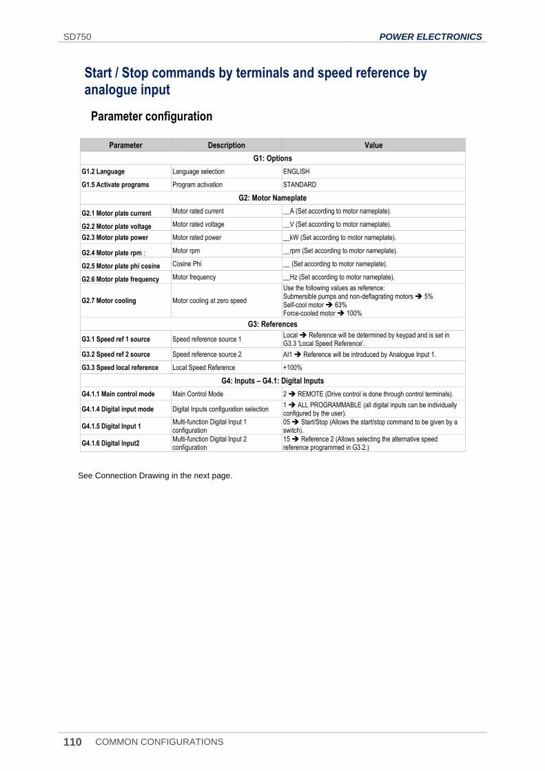
SD750 POWER ELECTRONICS
110 COMMON CONFIGURATIONS
Start / Stop commands by terminals and speed reference by analogue input
Parameter configuration
Parameter Description Value
G1: Options
G1.2 Language Language selection ENGLISH
G1.5 Activate programs Program activation STANDARD
G2: Motor Nameplate
G2.1 Motor plate current Motor rated current __A (Set according to motor nameplate).
G2.2 Motor plate voltage Motor rated voltage __V (Set according to motor nameplate).
G2.3 Motor plate power Motor rated power __kW (Set according to motor nameplate).
G2.4 Motor plate rpm : Motor rpm __rpm (Set according to motor nameplate).
G2.5 Motor plate phi cosine Cosine Phi __ (Set according to motor nameplate).
G2.6 Motor plate frequency Motor frequency __Hz (Set according to motor nameplate).
G2.7 Motor cooling Motor cooling at zero speed
Use the following values as reference: Submersible pumps and non-deflagrating motors 5% Self-cool motor 63% Force-cooled motor 100%
G3: References
G3.1 Speed ref 1 source Speed reference source 1 Local Reference will be determined by keypad and is set in G3.3 'Local Speed Reference'.
G3.2 Speed ref 2 source Speed reference source 2 AI1 Reference will be introduced by Analogue Input 1.
G3.3 Speed local reference Local Speed Reference +100%
G4: Inputs – G4.1: Digital Inputs
G4.1.1 Main control mode Main Control Mode 2 REMOTE (Drive control is done through control terminals).
G4.1.4 Digital input mode Digital Inputs configuration selection 1 ALL PROGRAMMABLE (all digital inputs can be individually configured by the user).
G4.1.5 Digital Input 1 Multi-function Digital Input 1 configuration
05 Start/Stop (Allows the start/stop command to be given by a switch).
G4.1.6 Digital Input2 Multi-function Digital Input 2 configuration
15 Reference 2 (Allows selecting the alternative speed reference programmed in G3.2.)
See Connection Drawing in the next page.
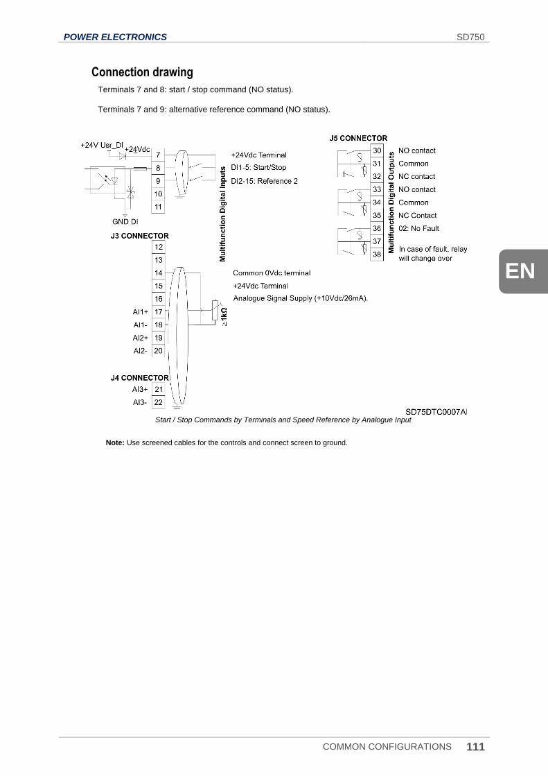
POWER ELECTRONICS SD750
COMMON CONFIGURATIONS 111
EN
Connection drawing
Terminals 7 and 8: start / stop command (NO status).
Terminals 7 and 9: alternative reference command (NO status).
Start / Stop Commands by Terminals and Speed Reference by Analogue Input
Note: Use screened cables for the controls and connect screen to ground.
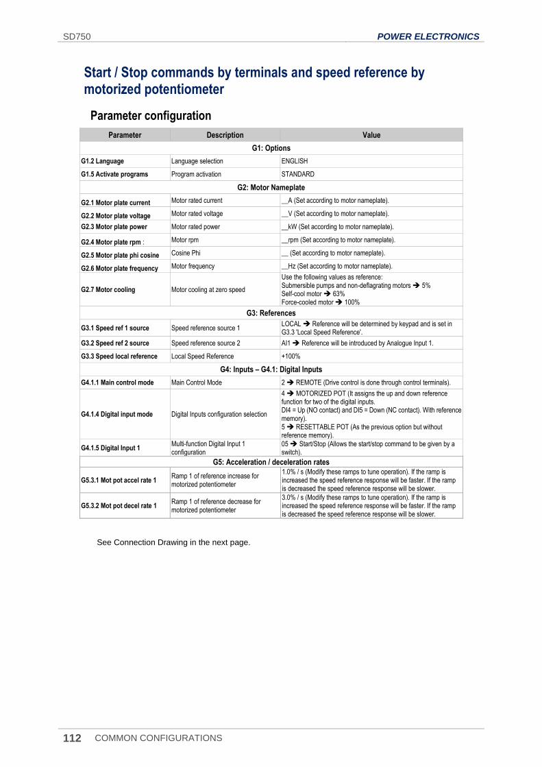
SD750 POWER ELECTRONICS
112 COMMON CONFIGURATIONS
Start / Stop commands by terminals and speed reference by motorized potentiometer
Parameter configuration
Parameter Description Value
G1: Options
G1.2 Language Language selection ENGLISH
G1.5 Activate programs Program activation STANDARD
G2: Motor Nameplate
G2.1 Motor plate current Motor rated current __A (Set according to motor nameplate).
G2.2 Motor plate voltage Motor rated voltage __V (Set according to motor nameplate).
G2.3 Motor plate power Motor rated power __kW (Set according to motor nameplate).
G2.4 Motor plate rpm : Motor rpm __rpm (Set according to motor nameplate).
G2.5 Motor plate phi cosine Cosine Phi __ (Set according to motor nameplate).
G2.6 Motor plate frequency Motor frequency __Hz (Set according to motor nameplate).
G2.7 Motor cooling Motor cooling at zero speed
Use the following values as reference: Submersible pumps and non-deflagrating motors 5% Self-cool motor 63% Force-cooled motor 100%
G3: References
G3.1 Speed ref 1 source Speed reference source 1 LOCAL Reference will be determined by keypad and is set in G3.3 'Local Speed Reference'.
G3.2 Speed ref 2 source Speed reference source 2 AI1 Reference will be introduced by Analogue Input 1.
G3.3 Speed local reference Local Speed Reference +100%
G4: Inputs – G4.1: Digital Inputs
G4.1.1 Main control mode Main Control Mode 2 REMOTE (Drive control is done through control terminals).
G4.1.4 Digital input mode Digital Inputs configuration selection
4 MOTORIZED POT (It assigns the up and down reference function for two of the digital inputs. DI4 = Up (NO contact) and DI5 = Down (NC contact). With reference memory). 5 RESETTABLE POT (As the previous option but without reference memory).
G4.1.5 Digital Input 1 Multi-function Digital Input 1 configuration
05 Start/Stop (Allows the start/stop command to be given by a switch).
G5: Acceleration / deceleration rates
G5.3.1 Mot pot accel rate 1 Ramp 1 of reference increase for motorized potentiometer
1.0% / s (Modify these ramps to tune operation). If the ramp is increased the speed reference response will be faster. If the ramp is decreased the speed reference response will be slower.
G5.3.2 Mot pot decel rate 1 Ramp 1 of reference decrease for motorized potentiometer
3.0% / s (Modify these ramps to tune operation). If the ramp is increased the speed reference response will be faster. If the ramp is decreased the speed reference response will be slower.
See Connection Drawing in the next page.
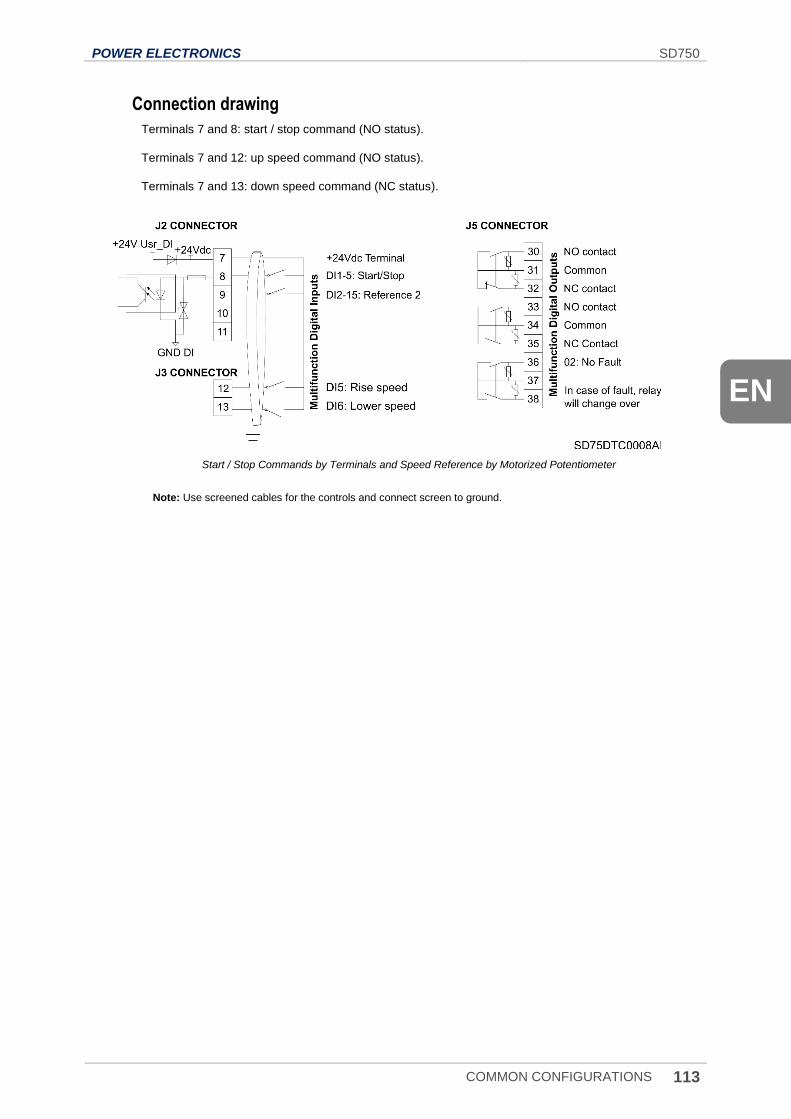
POWER ELECTRONICS SD750
COMMON CONFIGURATIONS 113
EN
Connection drawing
Terminals 7 and 8: start / stop command (NO status).
Terminals 7 and 12: up speed command (NO status).
Terminals 7 and 13: down speed command (NC status).
Start / Stop Commands by Terminals and Speed Reference by Motorized Potentiometer
Note: Use screened cables for the controls and connect screen to ground.
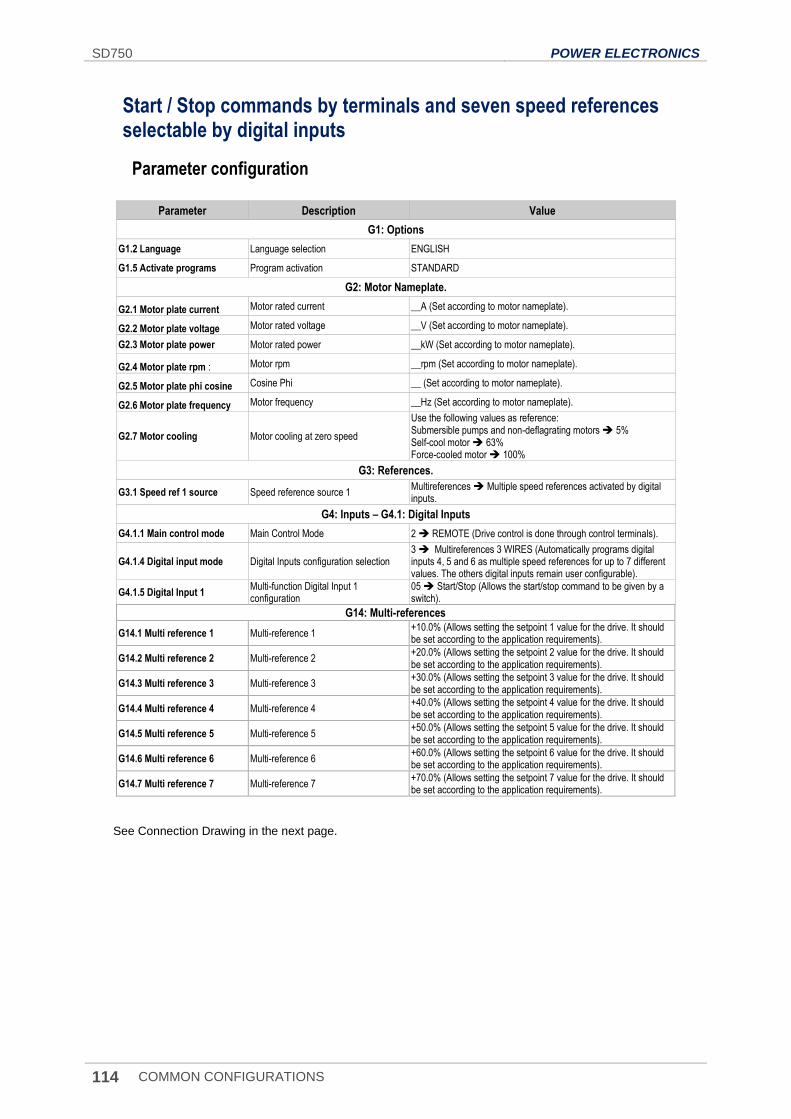
SD750 POWER ELECTRONICS
114 COMMON CONFIGURATIONS
Start / Stop commands by terminals and seven speed references selectable by digital inputs
Parameter configuration
Parameter Description Value
G1: Options
G1.2 Language Language selection ENGLISH
G1.5 Activate programs Program activation STANDARD
G2: Motor Nameplate.
G2.1 Motor plate current Motor rated current __A (Set according to motor nameplate).
G2.2 Motor plate voltage Motor rated voltage __V (Set according to motor nameplate).
G2.3 Motor plate power Motor rated power __kW (Set according to motor nameplate).
G2.4 Motor plate rpm : Motor rpm __rpm (Set according to motor nameplate).
G2.5 Motor plate phi cosine Cosine Phi __ (Set according to motor nameplate).
G2.6 Motor plate frequency Motor frequency __Hz (Set according to motor nameplate).
G2.7 Motor cooling Motor cooling at zero speed
Use the following values as reference: Submersible pumps and non-deflagrating motors 5% Self-cool motor 63% Force-cooled motor 100%
G3: References.
G3.1 Speed ref 1 source Speed reference source 1 Multireferences Multiple speed references activated by digital inputs.
G4: Inputs – G4.1: Digital Inputs
G4.1.1 Main control mode Main Control Mode 2 REMOTE (Drive control is done through control terminals).
G4.1.4 Digital input mode Digital Inputs configuration selection 3 Multireferences 3 WIRES (Automatically programs digital inputs 4, 5 and 6 as multiple speed references for up to 7 different values. The others digital inputs remain user configurable).
G4.1.5 Digital Input 1 Multi-function Digital Input 1 configuration
05 Start/Stop (Allows the start/stop command to be given by a switch).
G14: Multi-references
G14.1 Multi reference 1 Multi-reference 1 +10.0% (Allows setting the setpoint 1 value for the drive. It should be set according to the application requirements).
G14.2 Multi reference 2 Multi-reference 2 +20.0% (Allows setting the setpoint 2 value for the drive. It should be set according to the application requirements).
G14.3 Multi reference 3 Multi-reference 3 +30.0% (Allows setting the setpoint 3 value for the drive. It should be set according to the application requirements).
G14.4 Multi reference 4 Multi-reference 4 +40.0% (Allows setting the setpoint 4 value for the drive. It should be set according to the application requirements).
G14.5 Multi reference 5 Multi-reference 5 +50.0% (Allows setting the setpoint 5 value for the drive. It should be set according to the application requirements).
G14.6 Multi reference 6 Multi-reference 6 +60.0% (Allows setting the setpoint 6 value for the drive. It should be set according to the application requirements).
G14.7 Multi reference 7 Multi-reference 7 +70.0% (Allows setting the setpoint 7 value for the drive. It should be set according to the application requirements).
See Connection Drawing in the next page.
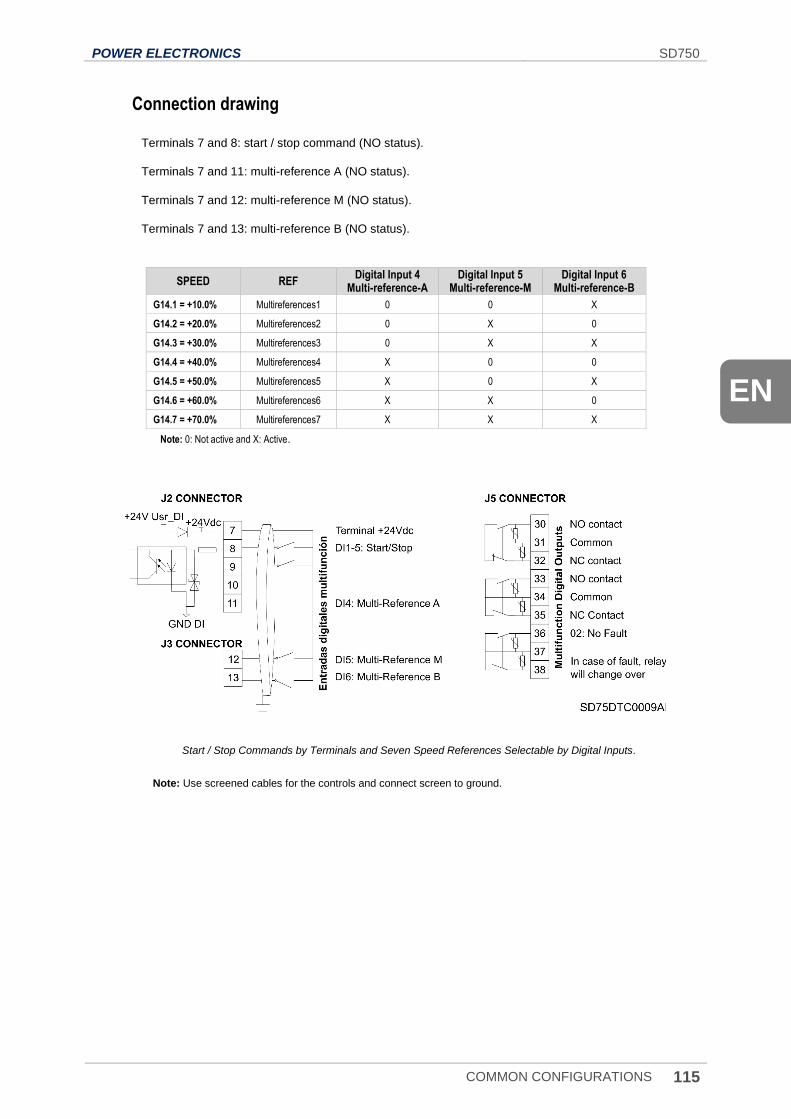
POWER ELECTRONICS SD750
COMMON CONFIGURATIONS 115
EN
Connection drawing
Terminals 7 and 8: start / stop command (NO status).
Terminals 7 and 11: multi-reference A (NO status).
Terminals 7 and 12: multi-reference M (NO status).
Terminals 7 and 13: multi-reference B (NO status).
SPEED REF Digital Input 4
Multi-reference-A Digital Input 5
Multi-reference-M Digital Input 6
Multi-reference-B
G14.1 = +10.0% Multireferences1 0 0 X
G14.2 = +20.0% Multireferences2 0 X 0
G14.3 = +30.0% Multireferences3 0 X X
G14.4 = +40.0% Multireferences4 X 0 0
G14.5 = +50.0% Multireferences5 X 0 X
G14.6 = +60.0% Multireferences6 X X 0
G14.7 = +70.0% Multireferences7 X X X
Note: 0: Not active and X: Active.
Start / Stop Commands by Terminals and Seven Speed References Selectable by Digital Inputs.
Note: Use screened cables for the controls and connect screen to ground.
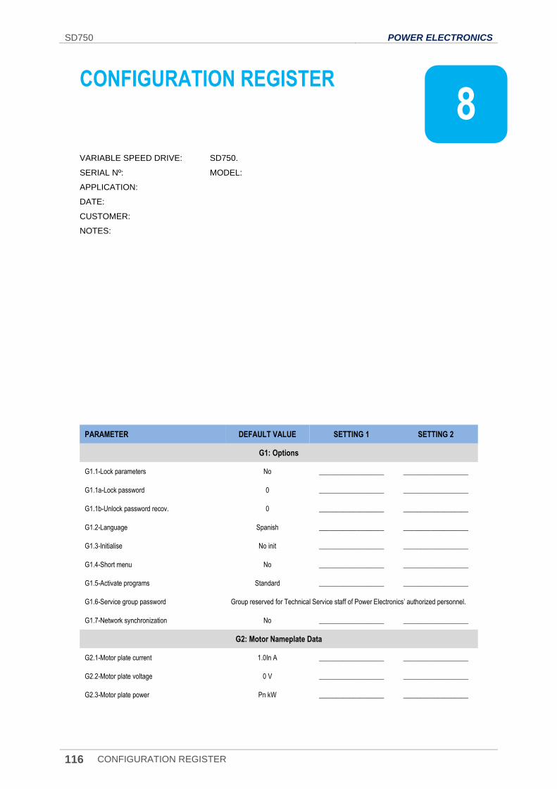
SD750 POWER ELECTRONICS
116 CONFIGURATION REGISTER
8. CONFIGURATION REGISTER
VARIABLE SPEED DRIVE: SD750.
SERIAL Nº: MODEL:
APPLICATION:
DATE:
CUSTOMER:
NOTES:
PARAMETER DEFAULT VALUE SETTING 1 SETTING 2
G1: Options
G1.1-Lock parameters No ___________________ ___________________
G1.1a-Lock password 0 ___________________ ___________________
G1.1b-Unlock password recov. 0 ___________________ ___________________
G1.2-Language Spanish ___________________ ___________________
G1.3-Initialise No init ___________________ ___________________
G1.4-Short menu No ___________________ ___________________
G1.5-Activate programs Standard ___________________ ___________________
G1.6-Service group password Group reserved for Technical Service staff of Power Electronics’ authorized personnel.
G1.7-Network synchronization No ___________________ ___________________
G2: Motor Nameplate Data
G2.1-Motor plate current 1.0In A ___________________ ___________________
G2.2-Motor plate voltage 0 V ___________________ ___________________
G2.3-Motor plate power Pn kW ___________________ ___________________
8
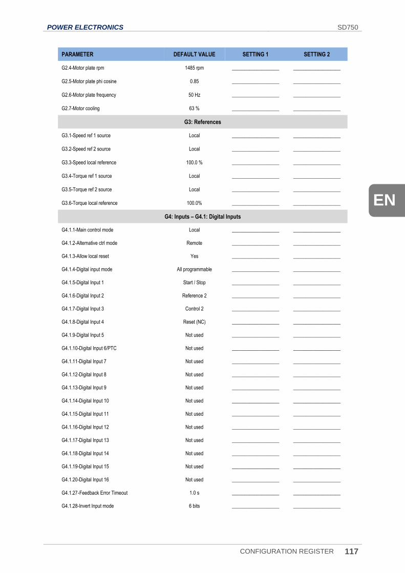
POWER ELECTRONICS SD750
CONFIGURATION REGISTER 117
EN
PARAMETER DEFAULT VALUE SETTING 1 SETTING 2
G2.4-Motor plate rpm 1485 rpm ___________________ ___________________
G2.5-Motor plate phi cosine 0.85 ___________________ ___________________
G2.6-Motor plate frequency 50 Hz ___________________ ___________________
G2.7-Motor cooling 63 % ___________________ ___________________
G3: References
G3.1-Speed ref 1 source Local ___________________ ___________________
G3.2-Speed ref 2 source Local ___________________ ___________________
G3.3-Speed local reference 100.0 % ___________________ ___________________
G3.4-Torque ref 1 source Local ___________________ ___________________
G3.5-Torque ref 2 source Local ___________________ ___________________
G3.6-Torque local reference 100.0% ___________________ ___________________
G4: Inputs – G4.1: Digital Inputs
G4.1.1-Main control mode Local ___________________ ___________________
G4.1.2-Alternative ctrl mode Remote ___________________ ___________________
G4.1.3-Allow local reset Yes ___________________ ___________________
G4.1.4-Digital input mode All programmable ___________________ ___________________
G4.1.5-Digital Input 1 Start / Stop ___________________ ___________________
G4.1.6-Digital Input 2 Reference 2 ___________________ ___________________
G4.1.7-Digital Input 3 Control 2 ___________________ ___________________
G4.1.8-Digital Input 4 Reset (NC) ___________________ ___________________
G4.1.9-Digital Input 5 Not used ___________________ ___________________
G4.1.10-Digital Input 6/PTC Not used ___________________ ___________________
G4.1.11-Digital Input 7 Not used ___________________ ___________________
G4.1.12-Digital Input 8 Not used ___________________ ___________________
G4.1.13-Digital Input 9 Not used ___________________ ___________________
G4.1.14-Digital Input 10 Not used ___________________ ___________________
G4.1.15-Digital Input 11 Not used ___________________ ___________________
G4.1.16-Digital Input 12 Not used ___________________ ___________________
G4.1.17-Digital Input 13 Not used ___________________ ___________________
G4.1.18-Digital Input 14 Not used ___________________ ___________________
G4.1.19-Digital Input 15 Not used ___________________ ___________________
G4.1.20-Digital Input 16 Not used ___________________ ___________________
G4.1.27-Feedback Error Timeout 1.0 s ___________________ ___________________
G4.1.28-Invert Input mode 6 bits ___________________ ___________________
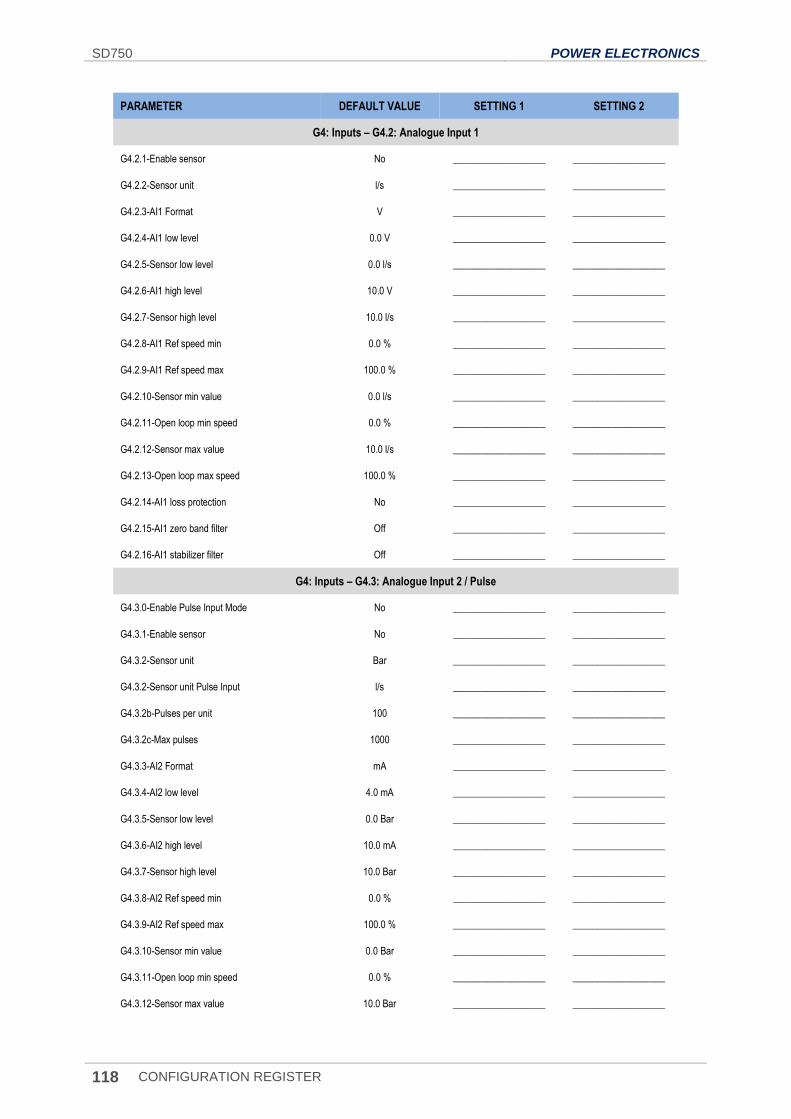
SD750 POWER ELECTRONICS
118 CONFIGURATION REGISTER
PARAMETER DEFAULT VALUE SETTING 1 SETTING 2
G4: Inputs – G4.2: Analogue Input 1
G4.2.1-Enable sensor No ___________________ ___________________
G4.2.2-Sensor unit l/s ___________________ ___________________
G4.2.3-AI1 Format V ___________________ ___________________
G4.2.4-AI1 low level 0.0 V ___________________ ___________________
G4.2.5-Sensor low level 0.0 l/s ___________________ ___________________
G4.2.6-AI1 high level 10.0 V ___________________ ___________________
G4.2.7-Sensor high level 10.0 l/s ___________________ ___________________
G4.2.8-AI1 Ref speed min 0.0 % ___________________ ___________________
G4.2.9-AI1 Ref speed max 100.0 % ___________________ ___________________
G4.2.10-Sensor min value 0.0 l/s ___________________ ___________________
G4.2.11-Open loop min speed 0.0 % ___________________ ___________________
G4.2.12-Sensor max value 10.0 l/s ___________________ ___________________
G4.2.13-Open loop max speed 100.0 % ___________________ ___________________
G4.2.14-AI1 loss protection No ___________________ ___________________
G4.2.15-AI1 zero band filter Off ___________________ ___________________
G4.2.16-AI1 stabilizer filter Off ___________________ ___________________
G4: Inputs – G4.3: Analogue Input 2 / Pulse
G4.3.0-Enable Pulse Input Mode No ___________________ ___________________
G4.3.1-Enable sensor No ___________________ ___________________
G4.3.2-Sensor unit Bar ___________________ ___________________
G4.3.2-Sensor unit Pulse Input l/s ___________________ ___________________
G4.3.2b-Pulses per unit 100 ___________________ ___________________
G4.3.2c-Max pulses 1000 ___________________ ___________________
G4.3.3-AI2 Format mA ___________________ ___________________
G4.3.4-AI2 low level 4.0 mA ___________________ ___________________
G4.3.5-Sensor low level 0.0 Bar ___________________ ___________________
G4.3.6-AI2 high level 10.0 mA ___________________ ___________________
G4.3.7-Sensor high level 10.0 Bar ___________________ ___________________
G4.3.8-AI2 Ref speed min 0.0 % ___________________ ___________________
G4.3.9-AI2 Ref speed max 100.0 % ___________________ ___________________
G4.3.10-Sensor min value 0.0 Bar ___________________ ___________________
G4.3.11-Open loop min speed 0.0 % ___________________ ___________________
G4.3.12-Sensor max value 10.0 Bar ___________________ ___________________
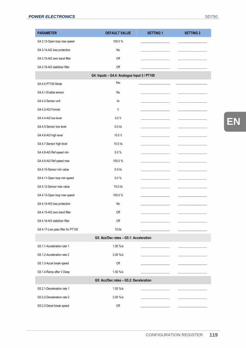
POWER ELECTRONICS SD750
CONFIGURATION REGISTER 119
EN
PARAMETER DEFAULT VALUE SETTING 1 SETTING 2
G4.3.13-Open loop max speed 100.0 % ___________________ ___________________
G4.3.14-AI2 loss protection No ___________________ ___________________
G4.3.15-AI2 zero band filter Off ___________________ ___________________
G4.3.16-AI2 stabilizer filter Off ___________________ ___________________
G4: Inputs – G4.4: Analogue Input 3 / PT100
G4.4.0-PT100 Mode No _________________ _________________
G4.4.1-Enable sensor No ___________________ ___________________
G4.4.2-Sensor unit l/s ___________________ ___________________
G4.4.3-AI3 Format V ___________________ ___________________
G4.4.4-AI3 low level 0.0 V ___________________ ___________________
G4.4.5-Sensor low level 0.0 l/s ___________________ ___________________
G4.4.6-AI3 high level 10.0 V ___________________ ___________________
G4.4.7-Sensor high level 10.0 l/s ___________________ ___________________
G4.4.8-AI3 Ref speed min 0.0 % ___________________ ___________________
G4.4.9-AI3 Ref speed max 100.0 % ___________________ ___________________
G4.4.10-Sensor min value 0.0 l/s ___________________ ___________________
G4.4.11-Open loop min speed 0.0 % ___________________ ___________________
G4.4.12-Sensor max value 10.0 l/s ___________________ ___________________
G4.4.13-Open loop max speed 100.0 % ___________________ ___________________
G4.4.14-AI3 loss protection No ___________________ ___________________
G4.4.15-AI3 zero band filter Off ___________________ ___________________
G4.4.16-AI3 stabilizer filter Off ___________________ ___________________
G4.4.17-Low pass filter for PT100 10.0s ___________________ ___________________
G5: Acc/Dec rates – G5.1: Acceleration
G5.1.1-Acceleration rate 1 1.50 %/s ___________________ ___________________
G5.1.2-Acceleration rate 2 2.00 %/s ___________________ ___________________
G5.1.3-Accel break speed Off ___________________ ___________________
G5.1.4-Ramp after V.Deep 1.50 %/s ___________________ ___________________
G5: Acc/Dec rates – G5.2: Deceleration
G5.2.1-Deceleration rate 1 1.50 %/s ___________________ ___________________
G5.2.2-Deceleration rate 2 2.00 %/s ___________________ ___________________
G5.2.3-Decel break speed Off ___________________ ___________________
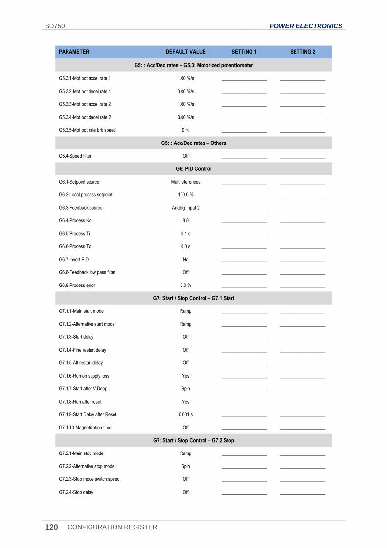
SD750 POWER ELECTRONICS
120 CONFIGURATION REGISTER
PARAMETER DEFAULT VALUE SETTING 1 SETTING 2
G5: : Acc/Dec rates – G5.3: Motorized potentiometer
G5.3.1-Mot pot accel rate 1 1.00 %/s ___________________ ___________________
G5.3.2-Mot pot decel rate 1 3.00 %/s ___________________ ___________________
G5.3.3-Mot pot accel rate 2 1.00 %/s ___________________ ___________________
G5.3.4-Mot pot decel rate 2 3.00 %/s ___________________ ___________________
G5.3.5-Mot pot rate brk speed 0 % ___________________ ___________________
G5: : Acc/Dec rates – Others
G5.4-Speed filter Off ___________________ ___________________
G6: PID Control
G6.1-Setpoint source Multireferences ___________________ ___________________
G6.2-Local process setpoint 100.0 % ___________________ ___________________
G6.3-Feedback source Analog Input 2 ___________________ ___________________
G6.4-Process Kc 8.0 ___________________ ___________________
G6.5-Process Ti 0.1 s ___________________ ___________________
G6.6-Process Td 0.0 s ___________________ ___________________
G6.7-Invert PID No ___________________ ___________________
G6.8-Feedback low pass filter Off ___________________ ___________________
G6.9-Process error 0.0 % ___________________ ___________________
G7: Start / Stop Control – G7.1 Start
G7.1.1-Main start mode Ramp ___________________ ___________________
G7.1.2-Alternative start mode Ramp ___________________ ___________________
G7.1.3-Start delay Off ___________________ ___________________
G7.1.4-Fine restart delay Off ___________________ ___________________
G7.1.5-Alt restart delay Off ___________________ ___________________
G7.1.6-Run on supply loss Yes ___________________ ___________________
G7.1.7-Start after V.Deep Spin ___________________ ___________________
G7.1.8-Run after reset Yes ___________________ ___________________
G7.1.9-Start Delay after Reset 0.001 s ___________________ ___________________
G7.1.10-Magnetization time Off ___________________ ___________________
G7: Start / Stop Control – G7.2 Stop
G7.2.1-Main stop mode Ramp ___________________ ___________________
G7.2.2-Alternative stop mode Spin ___________________ ___________________
G7.2.3-Stop mode switch speed Off ___________________ ___________________
G7.2.4-Stop delay Off ___________________ ___________________
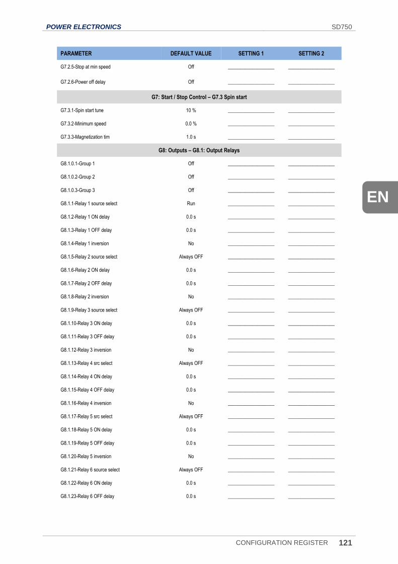
POWER ELECTRONICS SD750
CONFIGURATION REGISTER 121
EN
PARAMETER DEFAULT VALUE SETTING 1 SETTING 2
G7.2.5-Stop at min speed Off ___________________ ___________________
G7.2.6-Power off delay Off ___________________ ___________________
G7: Start / Stop Control – G7.3 Spin start
G7.3.1-Spin start tune 10 % ___________________ ___________________
G7.3.2-Minimum speed 0.0 % ___________________ ___________________
G7.3.3-Magnetization tim 1.0 s ___________________ ___________________
G8: Outputs – G8.1: Output Relays
G8.1.0.1-Group 1 Off ___________________ ___________________
G8.1.0.2-Group 2 Off ___________________ ___________________
G8.1.0.3-Group 3 Off ___________________ ___________________
G8.1.1-Relay 1 source select Run ___________________ ___________________
G8.1.2-Relay 1 ON delay 0.0 s ___________________ ___________________
G8.1.3-Relay 1 OFF delay 0.0 s ___________________ ___________________
G8.1.4-Relay 1 inversion No ___________________ ___________________
G8.1.5-Relay 2 source select Always OFF ___________________ ___________________
G8.1.6-Relay 2 ON delay 0.0 s ___________________ ___________________
G8.1.7-Relay 2 OFF delay 0.0 s ___________________ ___________________
G8.1.8-Relay 2 inversion No ___________________ ___________________
G8.1.9-Relay 3 source select Always OFF ___________________ ___________________
G8.1.10-Relay 3 ON delay 0.0 s ___________________ ___________________
G8.1.11-Relay 3 OFF delay 0.0 s ___________________ ___________________
G8.1.12-Relay 3 inversion No ___________________ ___________________
G8.1.13-Relay 4 src select Always OFF ___________________ ___________________
G8.1.14-Relay 4 ON delay 0.0 s ___________________ ___________________
G8.1.15-Relay 4 OFF delay 0.0 s ___________________ ___________________
G8.1.16-Relay 4 inversion No ___________________ ___________________
G8.1.17-Relay 5 src select Always OFF ___________________ ___________________
G8.1.18-Relay 5 ON delay 0.0 s ___________________ ___________________
G8.1.19-Relay 5 OFF delay 0.0 s ___________________ ___________________
G8.1.20-Relay 5 inversion No ___________________ ___________________
G8.1.21-Relay 6 source select Always OFF ___________________ ___________________
G8.1.22-Relay 6 ON delay 0.0 s ___________________ ___________________
G8.1.23-Relay 6 OFF delay 0.0 s ___________________ ___________________
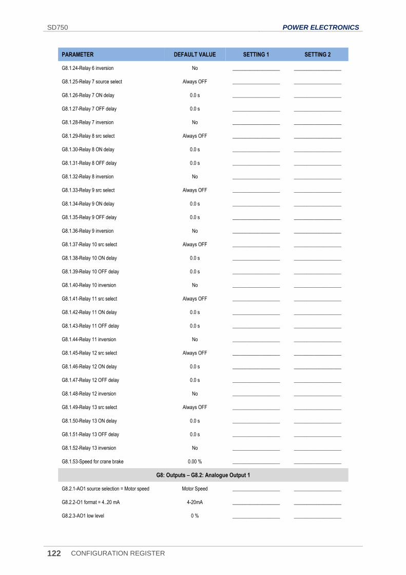
SD750 POWER ELECTRONICS
122 CONFIGURATION REGISTER
PARAMETER DEFAULT VALUE SETTING 1 SETTING 2
G8.1.24-Relay 6 inversion No ___________________ ___________________
G8.1.25-Relay 7 source select Always OFF ___________________ ___________________
G8.1.26-Relay 7 ON delay 0.0 s ___________________ ___________________
G8.1.27-Relay 7 OFF delay 0.0 s ___________________ ___________________
G8.1.28-Relay 7 inversion No ___________________ ___________________
G8.1.29-Relay 8 src select Always OFF ___________________ ___________________
G8.1.30-Relay 8 ON delay 0.0 s ___________________ ___________________
G8.1.31-Relay 8 OFF delay 0.0 s ___________________ ___________________
G8.1.32-Relay 8 inversion No ___________________ ___________________
G8.1.33-Relay 9 src select Always OFF ___________________ ___________________
G8.1.34-Relay 9 ON delay 0.0 s ___________________ ___________________
G8.1.35-Relay 9 OFF delay 0.0 s ___________________ ___________________
G8.1.36-Relay 9 inversion No ___________________ ___________________
G8.1.37-Relay 10 src select Always OFF ___________________ ___________________
G8.1.38-Relay 10 ON delay 0.0 s ___________________ ___________________
G8.1.39-Relay 10 OFF delay 0.0 s ___________________ ___________________
G8.1.40-Relay 10 inversion No ___________________ ___________________
G8.1.41-Relay 11 src select Always OFF ___________________ ___________________
G8.1.42-Relay 11 ON delay 0.0 s ___________________ ___________________
G8.1.43-Relay 11 OFF delay 0.0 s ___________________ ___________________
G8.1.44-Relay 11 inversion No ___________________ ___________________
G8.1.45-Relay 12 src select Always OFF ___________________ ___________________
G8.1.46-Relay 12 ON delay 0.0 s ___________________ ___________________
G8.1.47-Relay 12 OFF delay 0.0 s ___________________ ___________________
G8.1.48-Relay 12 inversion No ___________________ ___________________
G8.1.49-Relay 13 src select Always OFF ___________________ ___________________
G8.1.50-Relay 13 ON delay 0.0 s ___________________ ___________________
G8.1.51-Relay 13 OFF delay 0.0 s ___________________ ___________________
G8.1.52-Relay 13 inversion No ___________________ ___________________
G8.1.53-Speed for crane brake 0.00 % ___________________ ___________________
G8: Outputs – G8.2: Analogue Output 1
G8.2.1-AO1 source selection = Motor speed Motor Speed ___________________ ___________________
G8.2.2 -O1 format = 4..20 mA 4-20mA ___________________ ___________________
G8.2.3-AO1 low level 0 % ___________________ ___________________
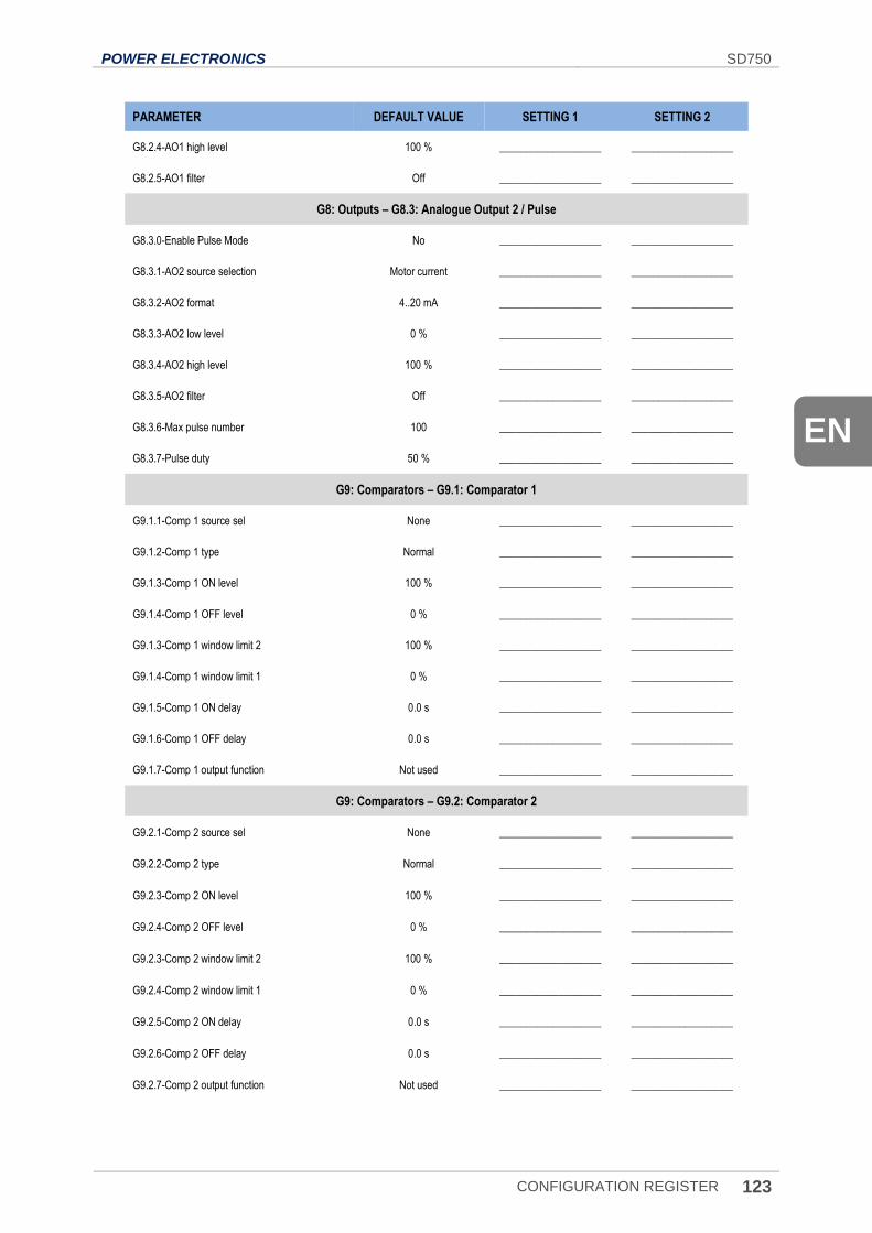
POWER ELECTRONICS SD750
CONFIGURATION REGISTER 123
EN
PARAMETER DEFAULT VALUE SETTING 1 SETTING 2
G8.2.4-AO1 high level 100 % ___________________ ___________________
G8.2.5-AO1 filter Off ___________________ ___________________
G8: Outputs – G8.3: Analogue Output 2 / Pulse
G8.3.0-Enable Pulse Mode No ___________________ ___________________
G8.3.1-AO2 source selection Motor current ___________________ ___________________
G8.3.2-AO2 format 4..20 mA ___________________ ___________________
G8.3.3-AO2 low level 0 % ___________________ ___________________
G8.3.4-AO2 high level 100 % ___________________ ___________________
G8.3.5-AO2 filter Off ___________________ ___________________
G8.3.6-Max pulse number 100 ___________________ ___________________
G8.3.7-Pulse duty 50 % ___________________ ___________________
G9: Comparators – G9.1: Comparator 1
G9.1.1-Comp 1 source sel None ___________________ ___________________
G9.1.2-Comp 1 type Normal ___________________ ___________________
G9.1.3-Comp 1 ON level 100 % ___________________ ___________________
G9.1.4-Comp 1 OFF level 0 % ___________________ ___________________
G9.1.3-Comp 1 window limit 2 100 % ___________________ ___________________
G9.1.4-Comp 1 window limit 1 0 % ___________________ ___________________
G9.1.5-Comp 1 ON delay 0.0 s ___________________ ___________________
G9.1.6-Comp 1 OFF delay 0.0 s ___________________ ___________________
G9.1.7-Comp 1 output function Not used ___________________ ___________________
G9: Comparators – G9.2: Comparator 2
G9.2.1-Comp 2 source sel None ___________________ ___________________
G9.2.2-Comp 2 type Normal ___________________ ___________________
G9.2.3-Comp 2 ON level 100 % ___________________ ___________________
G9.2.4-Comp 2 OFF level 0 % ___________________ ___________________
G9.2.3-Comp 2 window limit 2 100 % ___________________ ___________________
G9.2.4-Comp 2 window limit 1 0 % ___________________ ___________________
G9.2.5-Comp 2 ON delay 0.0 s ___________________ ___________________
G9.2.6-Comp 2 OFF delay 0.0 s ___________________ ___________________
G9.2.7-Comp 2 output function Not used ___________________ ___________________
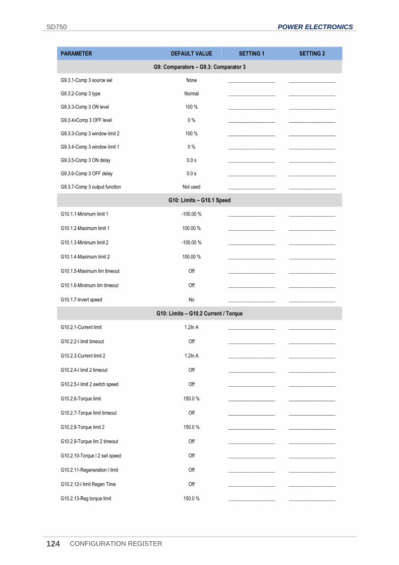
SD750 POWER ELECTRONICS
124 CONFIGURATION REGISTER
PARAMETER DEFAULT VALUE SETTING 1 SETTING 2
G9: Comparators – G9.3: Comparator 3
G9.3.1-Comp 3 source sel None ___________________ ___________________
G9.3.2-Comp 3 type Normal ___________________ ___________________
G9.3.3-Comp 3 ON level 100 % ___________________ ___________________
G9.3.4vComp 3 OFF level 0 % ___________________ ___________________
G9.3.3-Comp 3 window limit 2 100 % ___________________ ___________________
G9.3.4-Comp 3 window limit 1 0 % ___________________ ___________________
G9.3.5-Comp 3 ON delay 0.0 s ___________________ ___________________
G9.3.6-Comp 3 OFF delay 0.0 s ___________________ ___________________
G9.3.7-Comp 3 output function Not used ___________________ ___________________
G10: Limits – G10.1 Speed
G10.1.1-Minimum limit 1 -100.00 % ___________________ ___________________
G10.1.2-Maximum limit 1 100.00 % ___________________ ___________________
G10.1.3-Minimum limit 2 -100.00 % ___________________ ___________________
G10.1.4-Maximum limit 2 100.00 % ___________________ ___________________
G10.1.5-Maximum lim timeout Off ___________________ ___________________
G10.1.6-Minimum lim timeout Off ___________________ ___________________
G10.1.7-Invert speed No ___________________ ___________________
G10: Limits – G10.2 Current / Torque
G10.2.1-Current limit 1.2In A ___________________ ___________________
G10.2.2-I limit timeout Off ___________________ ___________________
G10.2.3-Current limit 2 1.2In A ___________________ ___________________
G10.2.4-I limit 2 timeout Off ___________________ ___________________
G10.2.5-I limit 2 switch speed Off ___________________ ___________________
G10.2.6-Torque limit 150.0 % ___________________ ___________________
G10.2.7-Torque limit timeout Off ___________________ ___________________
G10.2.8-Torque limit 2 150.0 % ___________________ ___________________
G10.2.9-Torque lim 2 timeout Off ___________________ ___________________
G10.2.10-Torque l 2 swt speed Off ___________________ ___________________
G10.2.11-Regeneration I limit Off ___________________ ___________________
G10.2.12-I limit Regen Time Off ___________________ ___________________
G10.2.13-Reg torque limit 150.0 % ___________________ ___________________
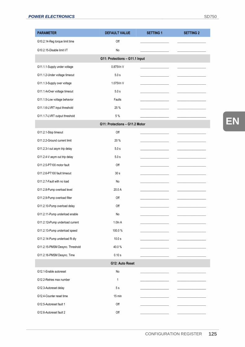
POWER ELECTRONICS SD750
CONFIGURATION REGISTER 125
EN
PARAMETER DEFAULT VALUE SETTING 1 SETTING 2
G10.2.14-Reg torque limit time Off ___________________ ___________________
G10.2.15-Disable limit I/T No ___________________ ___________________
G11: Protections – G11.1 Input
G11.1.1-Supply under voltage 0.875Vn V ___________________ ___________________
G11.1.2-Under voltage timeout 5.0 s ___________________ ___________________
G11.1.3-Supply over voltage 1.075Vn V ___________________ ___________________
G11.1.4vOver voltage timeout 5.0 s ___________________ ___________________
G11.1.5-Low voltage behavior Faults ___________________ ___________________
G11.1.6-LVRT input threshold 25 % ___________________ ___________________
G11.1.7-LVRT output threshold 5 % ___________________ ___________________
G11: Protections – G11.2 Motor
G11.2.1-Stop timeout Off ___________________ ___________________
G11.2.2-Ground current limit 20 % ___________________ ___________________
G11.2.3-I out asym trip delay 5.0 s ___________________ ___________________
G11.2.4-V asym out trip delay 5.0 s ___________________ ___________________
G11.2.5-PT100 motor fault Off ___________________ ___________________
G11.2.6-PT100 fault timeout 30 s ___________________ ___________________
G11.2.7-Fault with no load No ___________________ ___________________
G11.2.8-Pump overload level 20.0 A ___________________ ___________________
G11.2.9-Pump overload filter Off ___________________ ___________________
G11.2.10-Pump overload delay Off ___________________ ___________________
G11.2.11-Pump underload enable No ___________________ ___________________
G11.2.12vPump underload current 1.0In A ___________________ ___________________
G11.2.13-Pump underload speed 100.0 % ___________________ ___________________
G11.2.14-Pump underload flt dly 10.0 s ___________________ ___________________
G11.2.15-PMSM Desync. Threshold 40.0 % ___________________ ___________________
G11.2.16-PMSM Desync. Time 0.10 s ___________________ ___________________
G12: Auto Reset
G12.1-Enable autoreset No ___________________ ___________________
G12.2-Retries max number 1 ___________________ ___________________
G12.3-Autoreset delay 5 s ___________________ ___________________
G12.4-Counter reset time 15 min ___________________ ___________________
G12.5-Autoreset fault 1 Off ___________________ ___________________
G12.6-Autoreset fault 2 Off ___________________ ___________________
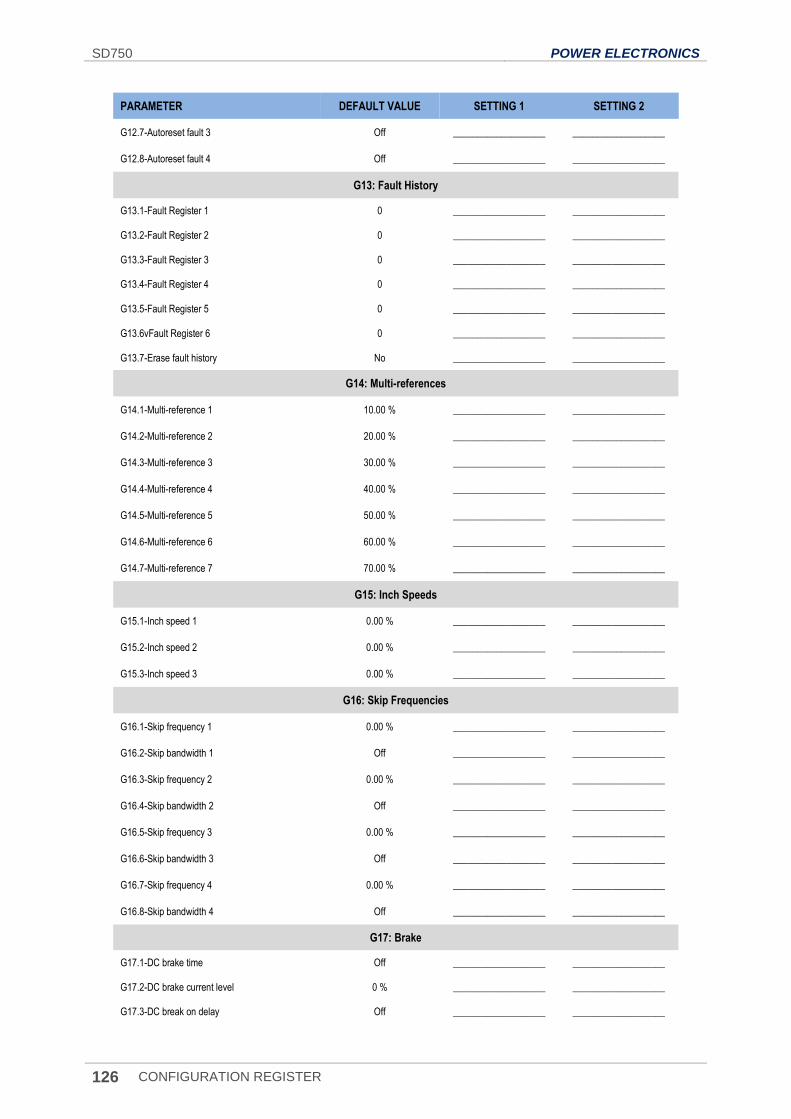
SD750 POWER ELECTRONICS
126 CONFIGURATION REGISTER
PARAMETER DEFAULT VALUE SETTING 1 SETTING 2
G12.7-Autoreset fault 3 Off ___________________ ___________________
G12.8-Autoreset fault 4 Off ___________________ ___________________
G13: Fault History
G13.1-Fault Register 1 0 ___________________ ___________________
G13.2-Fault Register 2 0 ___________________ ___________________
G13.3-Fault Register 3 0 ___________________ ___________________
G13.4-Fault Register 4 0 ___________________ ___________________
G13.5-Fault Register 5 0 ___________________ ___________________
G13.6vFault Register 6 0 ___________________ ___________________
G13.7-Erase fault history No ___________________ ___________________
G14: Multi-references
G14.1-Multi-reference 1 10.00 % ___________________ ___________________
G14.2-Multi-reference 2 20.00 % ___________________ ___________________
G14.3-Multi-reference 3 30.00 % ___________________ ___________________
G14.4-Multi-reference 4 40.00 % ___________________ ___________________
G14.5-Multi-reference 5 50.00 % ___________________ ___________________
G14.6-Multi-reference 6 60.00 % ___________________ ___________________
G14.7-Multi-reference 7 70.00 % ___________________ ___________________
G15: Inch Speeds
G15.1-Inch speed 1 0.00 % ___________________ ___________________
G15.2-Inch speed 2 0.00 % ___________________ ___________________
G15.3-Inch speed 3 0.00 % ___________________ ___________________
G16: Skip Frequencies
G16.1-Skip frequency 1 0.00 % ___________________ ___________________
G16.2-Skip bandwidth 1 Off ___________________ ___________________
G16.3-Skip frequency 2 0.00 % ___________________ ___________________
G16.4-Skip bandwidth 2 Off ___________________ ___________________
G16.5-Skip frequency 3 0.00 % ___________________ ___________________
G16.6-Skip bandwidth 3 Off ___________________ ___________________
G16.7-Skip frequency 4 0.00 % ___________________ ___________________
G16.8-Skip bandwidth 4 Off ___________________ ___________________
G17: Brake
G17.1-DC brake time Off ___________________ ___________________
G17.2-DC brake current level 0 % ___________________ ___________________
G17.3-DC break on delay Off ___________________ ___________________
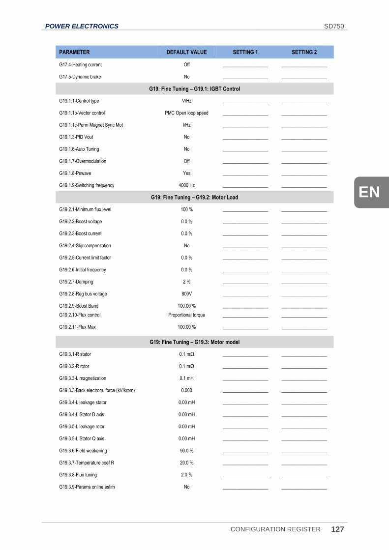
POWER ELECTRONICS SD750
CONFIGURATION REGISTER 127
EN
PARAMETER DEFAULT VALUE SETTING 1 SETTING 2
G17.4-Heating current Off ___________________ ___________________
G17.5-Dynamic brake No ___________________ ___________________
G19: Fine Tuning – G19.1: IGBT Control
G19.1.1-Control type V/Hz ___________________ ___________________
G19.1.1b-Vector control PMC Open loop speed ___________________ ___________________
G19.1.1c-Perm Magnet Sync Mot I/Hz ___________________ ___________________
G19.1.3-PID Vout No ___________________ ___________________
G19.1.6-Auto Tuning No ___________________ ___________________
G19.1.7-Overmodulation Off ___________________ ___________________
G19.1.8-Pewave Yes ___________________ ___________________
G19.1.9-Switching frequency 4000 Hz ___________________ ___________________
G19: Fine Tuning – G19.2: Motor Load
G19.2.1-Minimum flux level 100 % ___________________ ___________________
G19.2.2-Boost voltage 0.0 % ___________________ ___________________
G19.2.3-Boost current 0.0 % ___________________ ___________________
G19.2.4-Slip compensation No ___________________ ___________________
G19.2.5-Current limit factor 0.0 % ___________________ ___________________
G19.2.6-Initial frequency 0.0 % ___________________ ___________________
G19.2.7-Damping 2 % ___________________ ___________________
G19.2.8-Reg bus voltage 800V ___________________ ___________________
G19.2.9-Boost Band 100.00 % ___________________ ___________________
G19.2.10-Flux control Proportional torque ___________________ ___________________
G19.2.11-Flux Max 100.00 % ___________________ ___________________
G19: Fine Tuning – G19.3: Motor model
G19.3.1-R stator 0.1 mΩ ___________________ ___________________
G19.3.2-R rotor 0.1 mΩ ___________________ ___________________
G19.3.3-L magnetization 0.1 mH ___________________ ___________________
G19.3.3-Back electrom. force (kV/krpm) 0.000 ___________________ ___________________
G19.3.4-L leakage stator 0.00 mH ___________________ ___________________
G19.3.4-L Stator D axis 0.00 mH ___________________ ___________________
G19.3.5-L leakage rotor 0.00 mH ___________________ ___________________
G19.3.5-L Stator Q axis 0.00 mH ___________________ ___________________
G19.3.6-Field weakening 90.0 % ___________________ ___________________
G19.3.7-Temperature coef R 20.0 % ___________________ ___________________
G19.3.8-Flux tuning 2.0 % ___________________ ___________________
G19.3.9-Params online estim No ___________________ ___________________
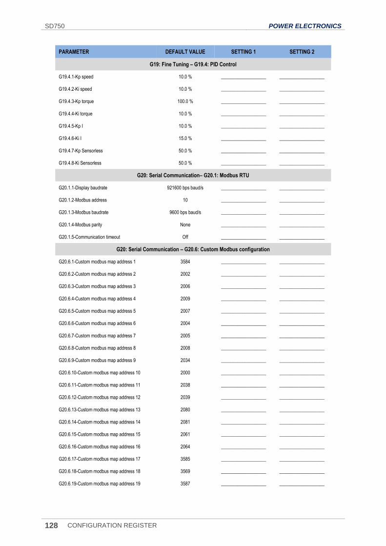
SD750 POWER ELECTRONICS
128 CONFIGURATION REGISTER
PARAMETER DEFAULT VALUE SETTING 1 SETTING 2
G19: Fine Tuning – G19.4: PID Control
G19.4.1-Kp speed 10.0 % ___________________ ___________________
G19.4.2-Ki speed 10.0 % ___________________ ___________________
G19.4.3-Kp torque 100.0 % ___________________ ___________________
G19.4.4-Ki torque 10.0 % ___________________ ___________________
G19.4.5-Kp I 10.0 % ___________________ ___________________
G19.4.6-Ki I 15.0 % ___________________ ___________________
G19.4.7-Kp Sensorless 50.0 % ___________________ ___________________
G19.4.8-Ki Sensorless 50.0 % ___________________ ___________________
G20: Serial Communication– G20.1: Modbus RTU
G20.1.1-Display baudrate 921600 bps baud/s ___________________ ___________________
G20.1.2-Modbus address 10 ___________________ ___________________
G20.1.3-Modbus baudrate 9600 bps baud/s ___________________ ___________________
G20.1.4-Modbus parity None ___________________ ___________________
G20.1.5-Communication timeout Off ___________________ ___________________
G20: Serial Communication – G20.6: Custom Modbus configuration
G20.6.1-Custom modbus map address 1 3584 ___________________ ___________________
G20.6.2-Custom modbus map address 2 2002 ___________________ ___________________
G20.6.3-Custom modbus map address 3 2006 ___________________ ___________________
G20.6.4-Custom modbus map address 4 2009 ___________________ ___________________
G20.6.5-Custom modbus map address 5 2007 ___________________ ___________________
G20.6.6-Custom modbus map address 6 2004 ___________________ ___________________
G20.6.7-Custom modbus map address 7 2005 ___________________ ___________________
G20.6.8-Custom modbus map address 8 2008 ___________________ ___________________
G20.6.9-Custom modbus map address 9 2034 ___________________ ___________________
G20.6.10-Custom modbus map address 10 2000 ___________________ ___________________
G20.6.11-Custom modbus map address 11 2038 ___________________ ___________________
G20.6.12-Custom modbus map address 12 2039 ___________________ ___________________
G20.6.13-Custom modbus map address 13 2080 ___________________ ___________________
G20.6.14-Custom modbus map address 14 2081 ___________________ ___________________
G20.6.15-Custom modbus map address 15 2061 ___________________ ___________________
G20.6.16-Custom modbus map address 16 2064 ___________________ ___________________
G20.6.17-Custom modbus map address 17 3585 ___________________ ___________________
G20.6.18-Custom modbus map address 18 3569 ___________________ ___________________
G20.6.19-Custom modbus map address 19 3587 ___________________ ___________________
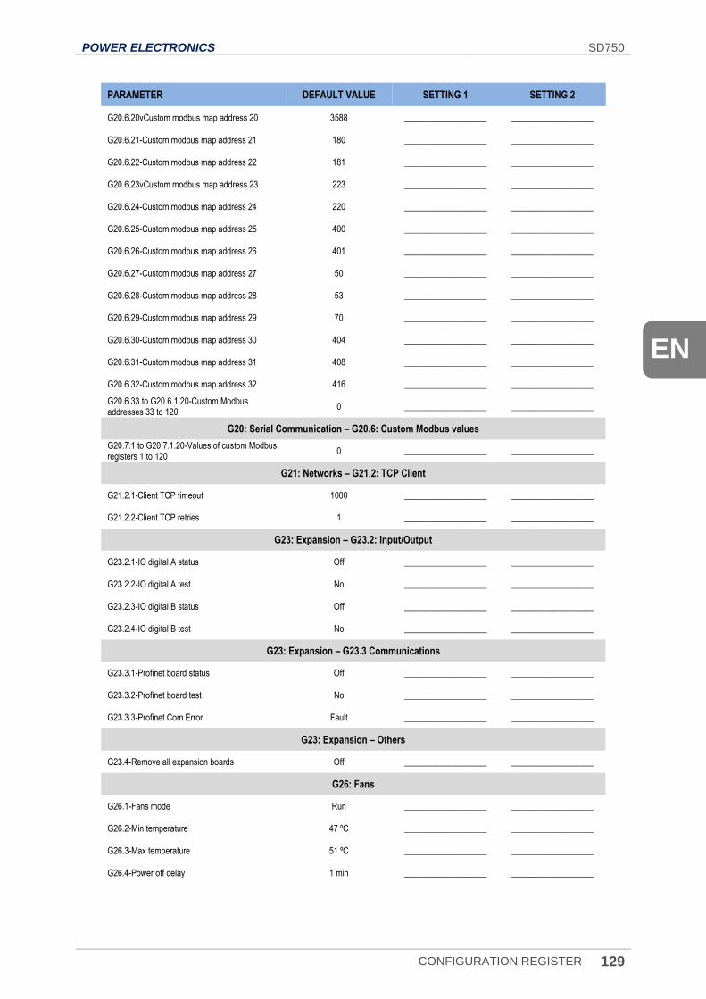
POWER ELECTRONICS SD750
CONFIGURATION REGISTER 129
EN
PARAMETER DEFAULT VALUE SETTING 1 SETTING 2
G20.6.20vCustom modbus map address 20 3588 ___________________ ___________________
G20.6.21-Custom modbus map address 21 180 ___________________ ___________________
G20.6.22-Custom modbus map address 22 181 ___________________ ___________________
G20.6.23vCustom modbus map address 23 223 ___________________ ___________________
G20.6.24-Custom modbus map address 24 220 ___________________ ___________________
G20.6.25-Custom modbus map address 25 400 ___________________ ___________________
G20.6.26-Custom modbus map address 26 401 ___________________ ___________________
G20.6.27-Custom modbus map address 27 50 ___________________ ___________________
G20.6.28-Custom modbus map address 28 53 ___________________ ___________________
G20.6.29-Custom modbus map address 29 70 ___________________ ___________________
G20.6.30-Custom modbus map address 30 404 ___________________ ___________________
G20.6.31-Custom modbus map address 31 408 ___________________ ___________________
G20.6.32-Custom modbus map address 32 416 ___________________ ___________________
G20.6.33 to G20.6.1.20-Custom Modbus addresses 33 to 120
0 ___________________ ___________________
G20: Serial Communication – G20.6: Custom Modbus values
G20.7.1 to G20.7.1.20-Values of custom Modbus registers 1 to 120
0 ___________________ ___________________
G21: Networks – G21.2: TCP Client
G21.2.1-Client TCP timeout 1000 ___________________ ___________________
G21.2.2-Client TCP retries 1 ___________________ ___________________
G23: Expansion – G23.2: Input/Output
G23.2.1-IO digital A status Off ___________________ ___________________
G23.2.2-IO digital A test No ___________________ ___________________
G23.2.3-IO digital B status Off ___________________ ___________________
G23.2.4-IO digital B test No ___________________ ___________________
G23: Expansion – G23.3 Communications
G23.3.1-Profinet board status Off ___________________ ___________________
G23.3.2-Profinet board test No ___________________ ___________________
G23.3.3-Profinet Com Error Fault ___________________ ___________________
G23: Expansion – Others
G23.4-Remove all expansion boards Off ___________________ ___________________
G26: Fans
G26.1-Fans mode Run ___________________ ___________________
G26.2-Min temperature 47 ºC ___________________ ___________________
G26.3-Max temperature 51 ºC ___________________ ___________________
G26.4-Power off delay 1 min ___________________ ___________________

SD750 POWER ELECTRONICS
130 CONFIGURATION REGISTER


24H TECHNICAL ASSISTANCE 365 DAYS A YEAR
FIND YOUR NEAREST DELEGATION POWER-ELECTRONICS.COM/CONTACT/