softening and fracturing process in masonry arches · softening and fracturing process in masonry...
TRANSCRIPT
Softening and Fracturing Process in Masonry Arches
(Processo di fessurazj9n~ e assestarnento negli archi lapidei)
ALBERTO CARPINTERI . ANDREA CARPINTERI
lstituto di Scienza deite Costruzioni, Università d i 6010gna , 2 Viale Risorgimento. 40136 Bologna. Italy.
Abstract - The softening and fracturing process in shallow masonry arches is considered. Therefore a purely elastit çonstitutive law is assumed for the material, coupled with a fracturing crisis condition according to Fracture Mechanics concepts. It is numerically verified how the cracks contrai the line of thrust, 50 that the statical behaviour Df the structure is improved and the internai loadings are redistributed. It is then possible to define a parameter called "fracturing benefit". Mareever the intermediate stage of structural damage is caught, which occurs during the loading process and immediately follows and precedf:!s the situations relating to the traditional schemes of elastic and limit analysis.
Sommario - Si considera il problema dell'assestamento per fessurazione di archi elasto-softening ribassati. Si assume quindi una legge costitut iva dei materiale puramente elastica, abbinata ad una condizione d i crisi per fessur'az ione nel senso della Meccanica della Frattwa. Si verifica numericamente come la presenza di fessure controlli I'andamento della curva de lle pression i, in modo da migliorare il comportamento statico della struttura e da ridistribuirne le sollecitazioni interne, e si perviene alia definizione di un parametro detto "beneficio per fessurazione". Si coglie inoltre quella fase intermedia di danneggiamento d~la struttura, che si verifica durante il processo di carico e che immediatamente segue e precede le si tuaz ioni relative agli schemi tradizionali di calcolo elastico e a rottura.
S02
•
r 1. INTRODUCTION.
The analysis Df masonry structures constitutes a topic af growing interest, especially in retation to the recent seismicaJ events, ,which have caused damage to and fracturing af severa I ancient con· structions in Italy.
As regards arch·struct.ures, and more generally vau lt-structures, the traditional schemes of elastic and limit analysis [1). even if scient ifically settled, aften Jeave the structural engineer quite embarrassed. Namely, while the elastic analysis considers the structure completely in compression and then verifies the line Df thrust does not go out cf the inertial core, the lim it analysis is restricted to consider the material as completely incoherent (not traction bearirlg) and to verify the line of thrust does not go out of the volume of the arch itself. Therefore both t hese structural analysis schemes do not catch that intermediate stage of damaging, which occurs during the loading process of the structure and immediately follows and precedes the situations relating to the above-mentioned schemes. That is, while the elastic analysis describes the structure up to the rise of the first non-linearities, the lim it analysis takes into consideration only the last situation prior to the final collapse.
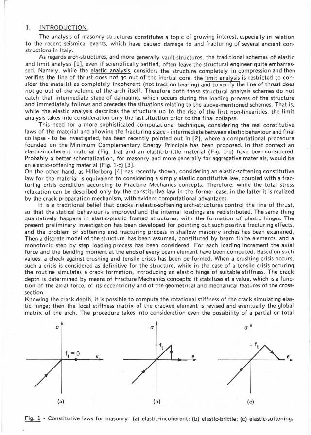
This need for a more sophisticated computational technique, considering the real constitutive laws of the material and allowing the fracturing stage - intermediate between elastic behaviour and final co llapse - to be investigated, has been recently pointed out in {2]. where a computational procedure founded on the Minimum Complementary Energy PrincipIe has been proposed. In that context an elastic-incoherent material (Fig. l-a) and an elastic-brittle material (Fig. l-b) have been considered. Probably a better schematization, for masonry and more generally for aggregative materiais, would be an elastic-softening material (Fig. l-c) [3] . On the other hand, as Hillerborg [4] has recently shown. considering an elastic-softening constitutive law for the material is equivalent to considering a simply elastic constitutive law. coupled with a fracturing crisis condit ion according to Fracture Mechanics concepts. Therefore. while the total stress relaxation can be described only by the constitutive law in the former case. in the latter lt is realized by the crack propagation mechanism, with evident computational advantages.
It is a traditional belief that cracks in elastic-softening arch-structures contrai the line of thrust, so that the statical behaviour is improved and the internai loadings are redistributed. The same thing qualitatively happens in elastic-plastic framed structures, with the formalion of plastic hinges. The present preliminary investigation has been developed for pointing out such positive fracturing effects. and the problem of softening and fracturing process in shallow masonry arches has been examined. Then a discrete model of the structure has been assumed, constituted by beam fin ite elements, and a monotonic step by step loading process has been considered. For each loading increment the axial force and the bending moment at the ends of every beam element have been computed. 8ased on such values, a check against crushing and tensile crises has been performed. When a crushing crisis occurs, such a crisis is considered as definitive for the structure, while in the case of a tensile crisis occuring the routine simulates a crack formation, introducing an elastic hinge of suitable stiffness. The crack depth is determined by means of Fracture Mechanies concepts: it stabilizes at a value, which is a function of the axial force, of its eccentricity and of the geometrical and mechanical features of the crosssection. Knowing the crack depth, it is possible to compute the rotational stiffness of the crack simulating elastie hinge; then the local stiffness matrix of the cracked element is revised and eventually the global matrix of the arch. The procedure takes into consideration even the possibility of a partial ar total
a a (]
• • •
(a) (b) (c)
~ - Constitutive laws for masonry: (a) elastic-incoherent; (b) elastie-brittle ; (c) elastic-softening.

crack closure, during loading increments following that of crack formation. As an illustrative application of the above mentioned procedure a family of shallow parabolic
arches, with constant span and variable rise, uniformly loaded along the span, will be numerically examined.
2. MECHANISMS OF CRACK OPENING AND CLOSURE.
As has already been anticipated in the Introduction, the elastic-softening material will be replaced by a purely elastic material with the possibility of crack formation and extension. $uch an hypothesis is valid only when the structure is sufficiently large so that stress profiles, close to those obtained from Linear Elastic Fracture Mechanics [3][5], can develop at middle distances from the crack tipo
As damage para meter, the relative crack depth ~ = a/b will be considered (Fig. 2-a) and, as loading parameter, the stress-intensity facto r KI (Fig. 2-b). which is an amplification facto r of the stress field when the loadings are only symmetrical (e.g. axial force and bending moment). The shear force will then be ignored.
a ~=
b
Ia (a)
M
b C F
K, IJ=-- r«b
.,f2;;'
r
"'-IJ
(b)
M
) Fig. 2 - Cracked beam element: (a) damage para meter ~; (b) loading parameter K,.
It is interesting to recall the energetic meaning of K 1c : the square of such a para meter - neglecting a facto r of proportionallty - namely represents the elastic energy released by the system in a virtual unit crack extension. When KI achieves its criticai value K 1C I it means that such an extension from virtual becomes real, since the released energy in an elementary crack extension is sufficient to provide the surface energy of the new topology.
As is well -known, a bending moment induces a stress-intensity factor at the crack tip equal to (Fig.2):
M K(MI = --V (~)
I b3,Q t M '
while a tensile axial force F induces the factor:
where the functions Y M and Y F' for O,ç ~,ç 0.7, are [6):
Y M (~) = 6 x (1.99 p/2 - 2.47 e12 + 12.97 ~'/2 - 23.17 r/2 + 24.80 e/2),
Y F W = 1.99 ~l/2 - 0.41 ~3/2 + 18.70 ~5/2 - 38.48 r ' 2 + 53.85 ~9/2.
(1 )
(2)
When the axial force F is a compression and the bending moment M tends to open the crack, as happens at the cross-sections of the arch-structures. the total stress-intensity factor can be obtained ap-
504

I
F= Fc
V" C b1/ 2 t K
1C [, 0,22 =Et I' -- I. 0.25
• 20
2 • • Ihickn.ss 01 lhe Mam
1 0.30
E 3 0.35 , ~ 10
"
0 .40
O 0.0 0.1 a
crack depth ~=-b
e , • . ~ - 10 , , z , "
!. = 0.20 0.22 0.25 0.30 0.35 -20 ,
Fig. 3 • Stability of fracturing process in an axially loaded beam.
plying the superposit ion principie :
K =KIMI_KIFI=_F_[-=-V (~)-V m] I I I b1/2 t b M F
(3)
where e indicates the eccentricity Df the equivalent eccentric axial force. From the criticai condition KI = K
1C' the dimensionless axial force of crack extension can be obtained.
as a function of the crack depth ~ and varying the relative eccentricity e/ b of the load (7):
1 (4)
The curves of Fig. 3 graphically represent expression (4) and show how - fixed the eccentricity e/bfracturing achieves a stable stage only after presenting an unstable one. If the load F has not the possibility to follow the unstable descending branch of the curve e/b = constant, in a "strain-softening" unloading process, fracturing will have catastrophical behaviour [8] and the representative point will horizontally advance in the diagram of Fig. 3 to meet again the curve e/ b = constant on its stable branch. On the other hand the load relaxat ion possibility, and then the more or less catastrophical fracturing behaviour, depends - as will be shown afterwards - on the geometrical and mechanical structural features, and especially on the degree of redundancy and on the sizes (scale effect).
Then it Is important to consider that, for each rei ative crack depth t a relative eccentricity e/b exists, under which crack closes again, at least partially. From the closing condition K, = O:
(5)
The curve of Fig. 4 graphically represents expression (5). The points under the curve represent cracks
50S

0.4
0.3 ~ 1.0
Z. 'ü .~ 0.2 C 1l ál .~ _ 0.1 .. ~
K, < O
0.1
a crack depth ~ = -
b Fig. 4 . Curve Df crack closure.
~{i=1 =A==iíy. M,
Fig. 5· Cracked beam finite element.
7
and loading conditions for which K. < O. Afterwards numerical examples will be shown where the crack will tend to close again; a fictitious crack depth ~* (Iower than the real depth ~) will be defined, obtainable from condition (5) (Fig. 4).
The stiffness 1055 of a cracked beam cross-section is eventual1y considered. Namely, while an uncracked cross-section of a beam element carries out an internai action of perfectly fixed joint. a cracked cross-section carries out an internai action of elasticly fixed joint. with rotational stiffness (Fig. 2-a):
w=-;:----fy~m d~
(6)
where E is the Voung's modulus of the material. Such a stiffness can be obtained by an energetic balance between elastic work and fracture work [9] .
The stiffne55 matrix of the cracked beam finite element (Fig. 5). i5 modified only in the four
506

r
F ,
T ,
M ,
F ,
T ,
M ,
rotationa l terms, as follows:
u, v, "', u, v,
EA - O O EA
- - - O O Q Q
EI EI EI EI 12 - -6 - O -12 - - 6-
Q3 Q' Q3 Q'
EI (3EI + 4QW) EI EI (3EI + 2QW) O 6 -
Q(EI +QW) Q' Q(EI + QW)
EA - O O Q
SYMMETRICAL EI EI
12- 6 -Q3 Q'
EI (3EI + 4QW)
Q(EI +QW)
(7)
where A and I indicate area and moment cf inertia of the cross-section , and Q is the length cf the beam finite element.
3. NUMERICAL EXAMPLES.
As a model structure, to which to apply the concepts introduced in the preceding section, consider the shallow arch cf Fig. 6, with constant span L = 50 m and variable rise h, rectangular cross-section cf thickness t ::;; 40 em and width b = 80 em, uni formly loaded along the span. Then hypothesize the arch as constituted in masonry, with tensile strength ft ::;; 30 kg cm- 2 , compression strength fe ::;; 500 kg em- 2 , and a criticai value K.c of the stress-intensity facto r equa l to 50 ar 100 kg cm- 3(2.
qj I I I I I I I I I I
--~ t ----. f L
Fig. 6 - Shallow arch-structure.
507

(7)
As a first case, let it be h/L = 1/20 and K ,C = 100 kg cm- 3/2. For q = 42.67 kg cm- 1 in the boundary finite elements the tensile strength ft and the compressive stres5 - 34l kg cm- 2 < te are reached. Then the rcutine computes the corresponding dimensionless axial force F c = 13.95 and the eccentricity e/b = 0.20. The diagram of Fig. 3 shows how, for sue h values, the crack formation is not ~ossible veto It is necessary to increase. the load q up to 51.86 kg em-I, 50 that the coupl~ ~.f values F'c = 16.96 and e/b = 0.20 can be achleved and a stable crack of depth t = 0.05 forms (mlnlmum of the curve e/b = 0.20 of Fig. 3). At this paint the rcutine verifies that other cracks can not form in the structure. besides those of the boundary elements. At the following step. an elastic hinge is introduced in the cracked elements, Le. the original structure is replaeed by anothet one of lower global stiffnes5, and the above deseribed proeedure is repeated, maintaining q = 51.86 kg em- I: the eraek depth remains 0.05 b. Then the load q is inereased to 60 kg cm- 1 , obtaining Fc = 19.62 and e/b = 0.20, and then t = 0.08. At the third step, with ~ = 0.08 and q = 60 kg em-I, the preceding results are obtained again and then the load is inereased to q = 62.38 kg em-I, achieving the crushing in the boundary elements (~ 500 kg cm-2). Such a collapse issupposed to be definitive.
As a second case, let it be h/L = 1/20 again and assume a lower fracture resistance K ,C = 50 kg cm- 3/2. In this case, for q = 42.67 kg cm- 1 , at the fixed ends one has Fc = 27.90 and e/b = 0.20, from which ~ ;: 0.105. The crack formation is allowed by the lower value K 1c ' which has now been chosen. At the second step, with t = 0.105 and q = 42.67 kg cm- 1 , one has Fc = 27.90 and e/b = 0.198 and then a depth t < 0.105. Then the routine resorts to the curve of closure (Fig. 4). which, for e/b = 0.198, gives t* = 0.130> 0.105. Thus the routine chooses the value t = 0.105. Then the load is increased up to q = 45 kg cm- l and the crack stabilizes for ~ = 0.110. At the third step (t = 0.110, q = 45 kg cm- 1 ) t = 0.110 results again, and the load is increased to 60 kg cm- 1 . The crack stabilizes for t = 0.120. At the fourth step, an increment of q to 62.38 kg cm- l produces the final crushing collapse, with a very slight delay compared to the case of uncracked structure.
As a third case, let it be h/ L = 1/30 and K1C
= 100 kg cm- 3/ 2 , For q = 7.71 kg cm- 1 , at the fixed ends, one has Fç = 3.36 and e/ b = 0.30, from which t = 0.335. At the second step, with t=0.335, one obtains Fc = 3.40 and e/ b = 0.28, from which the new depth is t = 0.225. Then it is necessary to apply the curve of closure (Fig. 4). which gives ~*= 0.385. Therefore the routine maintaines ~ ;; 0.335. For q = 17 kg cm- 1 , one obtains Fc = 7.51 and e/b = 0.28, and then t = 0.350. At the third step, with q = 38.46 kg em-I, the crushing collapse occurs. Observe how the load of definitive collapse is substantially higher than the load of first fracturing (Table 1).
508
Tab. 1 - Loads of first fracture qf and final cOllapse q, (L = 50m) .
1 100 0.83 1.00
20
1 50 0.68 1.00
20
1 100 0.21 1.05
30
1 50 0.21 1.05
30
1 100 0.15 1.11 40
1 50 0.15 0.15 40

r As a lourth case, consider h/ L = 1/30 and K,c = 50 kg cm- 3/2 . For q = 7.71 kg cm- 1 one has
t = 0.40 at the ends 01 the arch . At the second step,one obtains t = 0.26 and, appying the curve 01 crack closure, Iro~t = 0.40 and e/ b = 0.26 it lollows a real closure: t* = 0.35. At the third step, F c = 6.81 and e/ b = 0.27 provide t = 0.30, while the curve 01 closure gives t* = 0.38; therelore the crack stabilizes at t = 0.35. Increasing the load - q = 30 kg cm- 1 - it lollows t = 0.353. Then, for q ::;;:; 38.53 kg em- l , the crushing collapse oecurs. The uncracked structure would crush with q = 36.71 kg cm- 1 ; therefore the fracturing process has a "beneficiai eftect" on the load of collapse (Table 1) .
As a lifth case, consider h/ L= 1/40 and K,c = 100 kg cm- 3t2 • For q = 3.77 kg cm- 1 one has t = 0.67 at the arch ends. At the second step the crack closes: t* = 0.223 . At the lollowing steps the crack presents an oscillat ing behaviour: t = 0.58; t* = 0.40; t= 0.45. Eventually, lor q = 28.71 kg cm- 1 ,
the crushing collapse Decurs. The sarne collapse wauld occur for q:::: 25.82 kg cm- 1 in the uncracked structure (Table 1).
As a sixth and last case, consider h/L = 1/40 and K,c = 50 kg cm- 3/2 • Already lor q= 3. 77kg cm-1
it results ~ > 0.7 and then the fracture collapse comes betore the crushing collapse; thus the fracturing benefit has no way 01 being observed (1).
In lable 1, for eath rise h/L and eath considered K1C
value, the load qf of first fracturing and the load qc of f ina l collapse have been summarized õ they have been normalized by the load of crushing qo . related to the case in which the crack formation is not taken into consideration. The ratio qc / qo can be defined "fracturing benefit " and is analogous to the "plastic benefit" of the limit analysis.
In table 2 the results have then been reported, concerning the case in which the sizes of the previous examples are multiplied by 10 (L = 500 m, t = 4 m, b = 8 m) . It is possible to observe how two of the new computed ratios are lower than the corresponding ratios of Table 1. Ther:efore a scale effect is present; it means that the increase of the system size makes the system itself more brittle, independently 01 the constitutive law 01 the material [10] [11].
Tab. 2 - Loads 01 lirst collapse q, (L = 500m).
I h/L I K,c I 1 100
20
1 50 20
1 100 30
1 50 30
1 100 40
1 40 ' 50
(1) When t > 0.7, a deflnltlve fracture collapse is assumed.
fracture q, and final
0.68 1.00
0.68 1.00
0.21 1.05
0.21 1.05
0.15 0.15
.. 0.15 0.15
509

ACKNOWLEOGMENTS.
The authors gratefully acknowledge the financiai support cf the Italian National Research Council (C.N .R.).
References
[1] V. FRANCIOSI: L'attrito nel calcolo a rottura delle murature - Giornale dei Genio Civile. fasc. 7 - 8 - 9, pp. 215 - 234, 1980.
[2] A. BARATTA, M. VIGO and G. VOIELLO: Calcolo di archi in maleriale non resislenle a Irazione mediante il principio dei minimo lavaro complementare, "Consolidamento e Restauro Arq~ itet. lonico" - I Congresso Nazionale ASS.I.R.C.C O., Verona, 30 sept./3 ocl. 1981.
[3] Z.P. BAZANT: Inslabilily, Ouclilily and Size Effecl in Slrain-Softening Concrele - JourÁal of lhe Engineering Mechanics Oivision, A.S.C.E., Vol. 102, No. EM2, pp. 331 - 344, 1976.
[4] A. HILLERBORG, M. MOOEER and P.E. PETERSSON: Analysis of crack formalion and crack growth in concrete by means cf Fracture Mechanics and Finite Elements - Cement and CorÍ<:rete Research, Vol. 6, pp. 773 - 782, 1976. 1
[5] A. CARPINTERI: Applicat ion cf Fracture Mechanics to Concrete Structures - Journal df the Slruclural Oivision, A.S.C.E., April 1982.
[6] A. CARPINTERI: A Fraclure Mechanics Model for Reinforced Concrele Collapse, "Adv~nced Mechanics of Reinforced Concrele" - IABSE Colloguium Final Reporl, Oelft, 2/4 june i98l.
[7] A. CARPINTERI, A. DI TOMMASO and E. VIOLA : On lhe limil bearing capacily of crácked masonry walls (in Italian) - Proceedings 5th Congress cf the Italian Association cf Theoretical and Applied Mechanics (AIMETA), Palermo, 1980. .
[8] R. THOM: Slruclural slabilily and morphogenesis - Benjamin, New York, 1975. (9] A. CARPINTERI: Stiffness Loss and Fracture Resistanceof a Cracked Beam with Circular Çross
-Seclion - Inlernal Reporl n. 56 - I.S.C.B. , 1981. [10] A. CARPINTERI: Nolch Sensilivily in Fraclure Tesling of Aggregalive Maler ials - Engineering
Fracture Mechanics, to appear. [11] A. CARPINTERI: Static and energetic fracture parameters for rocks and concretes - Materia is
& Slruclures, R. I.L.E.M., Vol . 14, No. 81, pp. 151 - 162, 1981.
510