soft magnetic materials for audio transformers: history ... magnetic materials for audio...
TRANSCRIPT
Soft Magnetic Materials for Audio Transformers:History, Production, and Applications*
G. A. V. SOWTER
Sowter Audio Transformers, Ipswich IP1 2EL, Suffolk, UK
The history of soft magnetic materials is traced from 1000 B.C. to the present time. Thisincludes a description of the work of Oersted and Faraday who invented the firsttransformer, and the gradual improvements in core material over the last 150 years. Thesecover soft iron, silicon iron, grain orientation, Hi-B steels, domain control by lasers, andspark ablation. Amorphous metallic glasses are also detailed. Finally the design andcharacteristics of a wide range of audio transformers and magnetic shields are discussed, inparticular with regard to Mumetal, which with other nickel-iron alloys has been the author'slifetime occupation.
0 INTRODUCTION
The term "soft" relates to that class of metals or alloyswhich can be easily magnetized and demagnetized asopposed to "hard" magnetic materials used for permanentmagnets. This paper deals exclusively with soft materials,particularly for audio applications.
As far back as 1000 B.C. certain iron ores were found,mainly in Magnesia, a district of Macedonia, pieces ofwhich attracted and repelled each other. These containedFe304 (magnetite) and became known as lodestone, fromthe Saxon "loeden," to lead or direct. Lodestones as foundwere permanently magnetized and their power was named"magnetism." Around 55 B.C. Lucretius wrote "I haveseen Samothracean iron rings even jump up, and at thesame time filings of iron rave within brass basins whenthe magnet stone has been placed under." Later Plinyobserved that iron which has been well touched andrubbed with lodestone is able to take hold of other piecesof iron.
The first use of lodestone as a mariner's compass isattributed to the Chinese. Even before then, it was knownthat a piece of lodestone freely suspended always turns tothe North. The first compasses were magnetized ironneedles on floating straws, but pivoted devices weredeveloped. While visiting the Chinese National Museumin Peking some 20 years ago, the author was shown thewhole range of early Chinese compasses.
The first authentic treatise on the science of magnetismwas written in Latin by William Gilbert of Colchester
* Presented at the 82nd Convention of the Audio EngineeringSociety, London, 1987 March 10-13.
760
PAPERS
who had also studied electrostatics, a science dating backto about 600 B.C., when Thales, by rubbing amber withfur, gave the amber the power of picking up certainobjects. The Greek word for amber was "elektron," andfrom this our word "electricity" is derived. Over thecenturies considerable experimentation and the productionof friction machines to generate electrostatic charges werecompleted and included capacitors and spark dischargedevices. It was not until 1796 that Volta evolved thevoltaic pile to generate a continuous flow of electricity.This consisted of copper and zinc disks placed alternatelyin column form but prevented from touching each otherby means of pieces of moist cloth. This was later replacedby the voltaic cell which consisted of a copper and a zincstrip placed in dilute sulfuric acid and capable of beingjoined externally by copper wires to feed a load. As isknown, hydrogen gathers on the surface of the copperstrip and polarization takes place, limiting the currentoutput.
1 OERSTED'S DISCOVERYOF ELECTROMAGNETISM
Before we consider transformers, the production of amagnetic field by the presence of current is fundamental.In early 1820 the Danish physicist Oersted gave a series oflectures on magnetism and electricity. He made thecurrent from a galvanic trough (voltaic cells in series) passthrough a platinum wire to illustrate the heating effect(forerunner of modern electric heaters). Adjacent was acompass covered with glass, and in the course of thedemonstration, on making the circuit, in the presence ofthe audience, a slight flick of
J. Audio Eng. Soc., Vol. 35, No. 10, 1987 October

PAPERS
the compass needle was noticed. It was not considered tobe of very great significance, but months later, in 1820July, he resumed the research and confirmed that theneedle did actually move. By putting the compass, above,below, and on the sides of the wire carrying current heestablished that the wire was surrounded by a magneticfield. He immediately published a fourpage quartodocument in Latin, describing this epochmaking discovery,and sent it to all learned bodies and distinguishedscientists.
When several turns of wire were wound on amagnetizable core, such as iron, the field was greatlyenhanced, and in 1825 Sturgeon produced the firstelectromagnet. A typical example is the Royal Institution'sgreat electromagnet illustrated in Fig. 1. Electromagnetswere constructed by Franklin in the United States and G. I.Moll of Utrecht, Holland. Magnetizable materials knownat that time were various steels, wrought iron, nickel, andcobalt. (It is interesting to note that the nickel-cobalt alloyPermendur, a 20th-century U.S. discovery now inproduction, has the highest saturation induction of allwell-used commercial alloys, particularly for pole pieces.Some rare earth alloys with even higher saturations existbut are too expensive to come into general use.
Fig. 1. The Royal Institution's great electromagnet.J. Audio Eng. Soc., Vol. 35, No. 10, 1987 October
SOFT MAGNETIC MATERIALS FOR AUDIO TRANSFORMERS
2 FARADAY'S DISCOVERYOF ELECTROMAGNETIC INDUCTION
In the years 1821-1831 Michael Faraday became deeplyinterested in experimentation with electrically producedmagnetic fields and in November 1825 came very close todiscovering electromagnetic induction. He had fiveseparate wires, each 5 ft long, adjacent to each other, andhe passed a current through one of them trying to detectany effect on any of the neighboring wires. Unfortunatelyhis galvanometer was not a delicate one and no effect wasobservable. At that time a galvanometer, orcurrent-measuring device, was no more than a crudecompass near a coil of wire.
On 1828 February 15, at the usual Friday eveninggathering at the Royal Institution in London, there washeld what could have been the first meeting of our AudioEngineering Society. The subject of the lecture was"Resonance or the Reciprocation of Sound." Music wasdemonstrated on instruments from Java, the jew's harp, andwhistles, and a second meeting included sirens andstringed instruments. At the first lecture resonances wereproduced by the then well-known method of strewing sandon a circular disk and drawing a violin bow across theedge. The Chladni (1785) figures showed the naturalresonances of the disk. A second disk of similardimensions was placed under the energized one, which wassimilarly lightly covered with sand. It was then shown thatthe sand on the unenergized disk exhibited the samepattern of Chladni figures.
Michael Faraday was present at these demonstrationsand he perceived that the mechanical work of bowing hadbeen converted into sound energy and then reconvertedinto work on the second disk. This gave him a germ ofinspiration to determine whether electrical energy mightbe converted into magnetism and then reconverted intoelectricity.
Incidentally N. W. McLachlan and the author, in 1930,made Chladni figures with sand and lycopodium powderon disks and wide-angled metal and paper cones todiscover the natural resonances of loudspeakers bybowing. Subsequently energization of cones of many sizesand materials was made by passing audio frequencycurrent through the moving coil attached to the cone andthe sand studied. The frequencies at which these occurredwere confirmed by bridge measurement of the variationsof impedance and radiation resistance at each resonance[1]. It is worth recording that even the resonances of theactual moving coils were found to be audible by bowing,and the frequencies were measured.
Faraday, in 1831 August, did confirm that electricenergy could be converted to magnetism and back toelectricity by the following entry in his diary [2]:Have had an iron ring made (soft iron) round and '1/8 inchesthick and ring 6 inches in external diameter. Wound manycoils of copper wire round one half, the coils beingseparated by twine and calico-there were 3 lengths of wireabout 24 feet long and they could be connected as onelength or used as separate lengths. By trial with a trough,each was insulated from the other. Will call this side of the
761

SOWTER
side of the ring, but separated by an interval, was wound in twopieces together amounting to about 60 feet in length, the directionbeing as with the former coils; this side call B. Since the coil on Aintensified the effect of the current it was logical to presume thatcoil B would intensify the effect of the forces in the ring. Coil Awas capable of being connected to a trough and coil B wasconnected to a Galvanometer. When all was ready, connected theends of one of the pieces on A side with battery; immediately asensible effect on the needle. It oscillated and settled at last in theoriginal position. On breaking connection of A side with batteryagain a disturbance of the needle wave apparently short and sudden.
This is exactly what Faraday wrote in his diary.The discovery of electromagnetic induction resulted
from many months of experimental research which hecontinued for almost 30 years.
Faraday's induction ring was the first transformer evermade, and his description of the toroidal core andwindings does not differ greatly from that of a moderntoroidal mains transformer now so extensively used inaudio equipment (Fig. 2). He even had some idea of theeffect of the turns ratio but suffered from the fact thatcovered insulated wire was not then available.
During the nineteenth century wire coverings of silk orcotton in single or double layers, impregnated papers,Gutta Percha for submarine cables, and rubber wereutilized, to be followed eventually by enamel coatings.
It is worth recording that Faraday also invented the firstdynamo, which gave a supply of direct current from arotating disk (Fig. 3). This greatly enhanced the use ofdirect current for experimental and other purposes andbasically led to the manufacture of highpower commercialgenerators.
Toward the end of that century considerable researchwas undertaken on soft magnetic materials for generatorsand power transformers. The latter, in some instances,consisted of toroidal copper windings with as manysmall-diameter iron wires as possible, forced through thecentral aperture and bent back on themselves to completea magnetic core. Similar construction was used for smallcommunication transformers for telephones. For powertransformers an alternative construction was the use ofsoft iron plates bolted together, but these had appreciablelosses and suffered from deterioration due to aging.
3 PRODUCTION OF NICKEL-IRON ALLOYSIn about 1890 J. A. Ewing had published a book entitled
Magnetic Induction in Iron and Other Metals [3]. This is amost comprehensive study covering various magneticmeasurements, including Weber's ballistic method,magnetization of iron rings and long wires, steel, cast iron,nickel, cobalt, and wrought iron wires. A chapter dealswith hysteresis and the effects of vibration, together withmagnetizing in weak and strong fields. He also studiedeffects of temperature and stress, torsion and twisting, witha final chapter on practical magnetic testing. Consideringthat the period was 1890-1900, it is astonishing that suchcomprehensive
762
PAPERS
research was being carried out on so many magneticmaterials.
Another reason for mentioning this treatise is thatEwing, Hopkinson, and others almost anticipated thediscovery of modern high-permeability alloys such asMumetal and Permalloy, so widely used in audiotransformers. At that time tests were made on nickel-ironalloys containing 4.7% Ni, 25% Ni, 30% Ni, and 33% Ni.
Even the effects of annealing were observed, and hadthe nickel contents been increased further up to 80%, therewould have been created elementary forms of Invar (35%NiFe), Radiometal (50% NiFe), and Mumetal andPermalloy (73-80% NiFe).
After leaving the university in 1922, the author's firstlaboratory work was to measure the magnetic properties ofnickel-iron rods about 5 ft long and 0.25
Fig. 2. Page from Faraday's diary describing experiment andshowing his induction ring the first toroidal transformer.
J. Audio Eng. Soc., Vol. 35, No. 10, 1987 October

PAPERS
in diameter, containing 10%, 20%, 30%, 40%, 50%, 60%,70%, 80%, and 90% Ni. These had previously been heatedto about 1000°C and slow cooled. The test equipmentemployed, invented by Weber, is illustrated in Fig. 4,where a. ballistic galvanometer is used to measure flux.
These tests quickly indicated that as the nickel contentwas increased, there was an enormous improvement inmagnetic properties around about 78% Ni content, whichgave the optimum permeabilities.
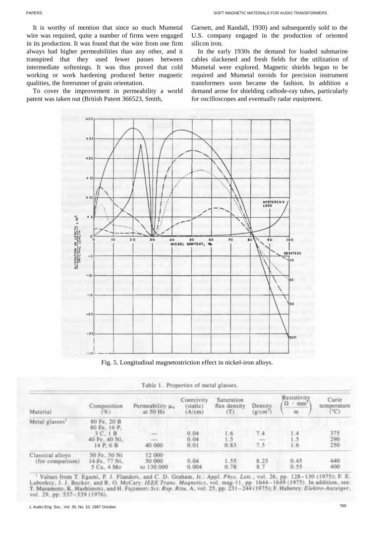
High permeability is closely allied with lowmagnetostriction, and some years later the author mademagnetostriction tests on a Mumetal rod, again using theWeber ballistic equipment. A 6-ft length of annealed thinMumetal rod was inserted in the magnetizing solenoid, andone end was securely fixed in a large lead block. At theother end a 2000x linear magnification Reichert measuringmicroscope with oil immersion was focused on the grainboundary of a crystal exposed by etching with nitric acid.The first observations showed that the whole laboratory,situated within the works, was in a state of vibration due tothe operation of hot and cold rolling mills and particularlya steam hammer. The result was that the measurements hadto be made in the middle of the night when all was quiet.The magnetostriction movement on the grain boundarywas on the order of one-millionth of its length for thatparticular specimen (Fig. 5). It is interesting to observe thathad magnetostriction measurements been made on theaforementioned series of rods, the optimum compositionfor high permeability might have been confirmed.
Another test carried out by the author was to measurethe permeability of a vertically suspended annealedMumetal wire when various loads were applied to thelower end. This clearly showed that as loads were in
Fig. 3. Page from Faraday's diary showing sketch of firstdynamo.
J. Audio Eng. Soc., Vol. 35, No. 10, 1987 October
SOFT MAGNETIC MATERIALS FOR AUDIO TRANSFORMERS
creased, there was first an improvement in permeabilityand then a decline. It is interesting to note that on modernHi-B transformer steel a small tensile stress is obtained byusing a glass surface coating applied at high temperatureand then cooling. This reduces the losses and raises thepermeability.4 DISCOVERY OF IRON ALLOYEDWITH SILICON FOR TRANSFORMER CONES
During the latter half of the nineteenth centuryconsiderable research on magnetic materials had beencarried out by such persons as Ewing, Rowlands, S. P.Thomson, Steinmetz, and many others, and measurementtechniques became well established. Many properties ofwrought iron, steels, nickel, cobalt, and even somenickel-iron alloys were determined, and it is to beregretted that the full import of the results was notrealized.
In the early 1900s that first major improvement inmaterials for transformers took place when Sir RobertHadfield introduced iron alloyed with silicon which gavehigher permeabilities and appreciably less loss than earliersteels. Various percentages of silicon were utilized and thealloys were sold under a variety of trade names. Thesewere produced from hot-rolled sheets and hadomnidirectional properties. Strain-relieving annealing wassometimes employed, and various coatings were used toreduce eddy current loss.
These sheets were used in the form of butt lapped stripsfor the magnetic cores or power transformers and had onlyabout half of the previous iron losses. The most popularalloy was 3-4% SiFe. Larger values of silicon contentwere investigated even up to 7%, which was found tohave superior magnetic properties, but the material wasbrittle and not easily machinable or stamped.
As an indication of the quality of silicon iron availablein 1915, reference is made to an IEE paper by N. W.McLachlan on Stalloy plates 0.5 mm thick for instrumenttransformers [4]. He found by measurement at 50 Hz thatat 0.01 T the complex permeability was 780 and at 0.1 T,2760. At 0.5 T the value was only 3000.
Fig. 4. Connections for testing iron rods by search coilmethod due to Weber.
763

SOWTER
5 GRAIN-ORIENTED SILICON IRON
Silicon irons with a number of improvements wereutilized for transformers until the late 1930s when abreakthrough occurred due to the introduction ofgrainoriented silicon iron. This was the importantinvention of N. P. Goss, who termed the product Gossiron [5].
This was achieved by altering the silicon content in thesteel, cold rolling the strip to the desired thickness,followed by high-temperature annealing at 1200°C toevolve secondary recrystallization. Large grains wereproduced, oriented in the rolling direction and resulting ingreatly improved magnetic properties along the strip. Moreloss, however, arose across the strip, and this led toconsiderable research on mitered joints, butt joints, andmethods of utilizing as far as possible constructions wherethe flux went along the grains. Obviously toroids here hada big advantage, and subsequently C cores and E coreswere introduced, particularly for small transformers.
While improvements were taking place prior to the1960s such as making thinner Goss material to reduceeddy currents, research was continuing to produce bettersteels. Japan came to the fore and patented their Hi-BSteel which is extensively used today. Here larger grainsare evolved and a small tensile stress is imparted to thesteel by using a glass surface coating applied at hightemperature and resulting in reduced electrical loss.
6 RECENT DEVELOPMENTS
Even in the last few years significant improvements inelectrical steel production have been obtained. As is wellknown, magnetic losses in a core consist partly ofhysteresis, which varies linearly with frequency, and eddycurrent loss, which is proportional to the squares of sheetthickness, frequency, and induction, but inverselyproportional to resistivity. There is however a third loss,mentioned by the author in 1941 [6], which was termeddisaccommodation loss or Nachwirkung loss. It has beenfound that this loss depends on the distance betweendomain walls, and recently by a process of scribing andlaser treating the surface of the strip, losses can be reducedby as much as 10%. Richardson [5] gives further details ofthese treatments and states that electrical steels developedtoday give a 40% improvement on the Goss 0.35-mm strip.British steels are now using spark ablation to give the sameresults as laser scribing. So far, for use in audiotransformer cores, several grades of oriented strip areavailable, termed M grades, from M2 to M7, and these areutilized for the production of small toroids andlaminations. For these purposes the aforementioned veryhigh grade materials are not available yet, possibly foreconomic reasons.
It is noted that all efforts to improve steel materials areconcerned with reducing losses. Fortunately low lossusually means higher magnetic permeability, which in thecase of audio transformers is a most desirable
764
PAPERS
feature to obtain high inductance with the smallest numberof turns. The latter is required to minimize the capacityeffects, as described later.
7 METALLIC GLASS OR AMORPHOUS SOFTMAGNETIC ALLOYS
One final development in magnetic materials over tilelast 20 years has been the production of metallic glass, oramorphous soft magnetic alloys: These are like glass andhave no crystalline structure. They are produced bycontinuous casting and rapid continuous quenching, whichresults in a quick transition from the fluid to the solidphase. The virtue of these materials is that thin strips, suchas 0.05 mm thick (and up to 1 m wide in one instance), canbe made directly from the casting line, thus avoiding theusual hot rolling, cold rolling, and intermediate annealingprocesses. Unfortunately, like glass, they are hard and verybrittle which makes handling and cutting uneconomic.
The composition of metallic glasses may consist ofsome of the following: iron (Fe), boron (B), phosphorus(P), nickel (Ni), carbon (C), copper (Cu), and molybdenum(Mo), a few of these elements constituting a particularbrand. Table 1 gives the properties of metallic glasses thatexisted a few years ago, but research continues [7].
Amorphous metal has been employed in smalldistibution transformers, and a 16-kVA unit which hasonly 20% of the loss of normal oriented silicon steels hasbeen constructed. Amorphous metal is unlikely to be usedin large power transformers owing to its low saturationinduction, but in due course there is a possibility for itsuse in audio transformers if it can be considerablyreduced in price as compared even with Mumetal.
8 THE ORIGIN OF MUMETAL
In the early 1920s Mumetal was developed to act as aloading material for submarine telegraph cables. It wasproduced in high-frequency induction furnaces (theoriginal microwave oven principle), and the 20-lb ingotswere used to make wire 0.010 in diameter. In 1926 for thePacific submarine cable between Bamfield and Fanning,3370 nautical miles in length, thousands of miles of thisMumetal wire were drawn for wrapping around the centralcopper conductor to increase its inductance. This involvedsubsequent annealing to develop the high permeabilityrequired. The effect of the Mumetal wire was to reducegreatly the attenuation of the signals and increase theword-handling capacity. By passing the loaded copperthrough a continuous furnace at about 900°C in a nitrogenatmosphere it also meant continuous measurements ofinductance by the author and others on a definite length ofconductor after passage through the furnace.
1 Mumetal is a registered trademark of Telcon MetalsLtd., Crawley, Sussex, UK.
J. Audio Eng. Soc., Vol. 35, No. 10, 1987 October
PAPERS
It is worthy of mention that since so much Mumetalwire was required, quite a number of firms were engagedin its production. It was found that the wire from one firmalways had higher permeabilities than any other, and ittranspired that they used fewer passes betweenintermediate softenings. It was thus proved that coldworking or work hardening produced better magneticqualities, the forerunner of grain orientation.
To cover the improvement in permeability a worldpatent was taken out (British Patent 366523, Smith,
SOFT MAGNETIC MATERIALS FOR AUDIO TRANSFORMERS
Garnett, and Randall, 1930) and subsequently sold to theU.S. company engaged in the production of orientedsilicon iron.
In the early 1930s the demand for loaded submarinecables slackened and fresh fields for the utilization ofMumetal were explored. Magnetic shields began to berequired and Mumetal toroids for precision instrumenttransformers soon became the fashion. In addition ademand arose for shielding cathode-ray tubes, particularlyfor oscilloscopes and eventually radar equipment.
Fig. 5. Longitudinal magnetostriction effect in nickel-iron alloys.
J. Audio Eng. Soc., Vol. 35, No. 10, 1987 October 765

PAPERS
It is worthy of mention that since so much Mumetalwire was required, quite a number of firms were engagedin its production. It was found that the wire from one firmalways had higher permeabilities than any other, and ittranspired that they used fewer passes betweenintermediate softenings. It was thus proved that coldworking or work hardening produced better magneticqualities, the forerunner of grain orientation.
To cover the improvement in permeability a worldpatent was taken out (British Patent 366523, Smith,
SOFT MAGNETIC MATERIALS FOR AUDIO TRANSFORMERS
Garnett, and Randall, 1930) and subsequently sold to theU. S. company engaged in the production of orientedsilicon iron.
In the early 1930s the demand for loaded submarinecables slackened and fresh fields for the utilization ofMumetal were explored. Magnetic shields began to berequired and Mumetal toroids for precision instrumenttransformers soon became the fashion. In addition ademand arose for shielding cathode-ray tubes, particularlyfor oscilloscopes and eventually radar equipment.
Table 1. Properties of metal glasses.
J. Audio Eng. Soc., Vol. 35, No. 10, 1987 October 765
Fig. 5. Longitudinal magneto striction effect in nickel-iron alloys.
SOWTER
9 HISTORY OF AUDIO FREQUENCYTRANSFORMERS
The author's first experience with audio transformerswas in 1919 when he examined a war surplus audioamplifier which used "R" bright emitter valves andcontained three kinds of audio transformers. These wereinlet, intervalve, and output types and were all about 2 in 3
with Stalloy (4% silicon iron) cores. It is of interest to notethat a small brass plate on the amplifier case stated "madeby Captain Mullard" with a South London, Streatham,address. It is believed that subsequently he was the founderof the firm of Mullard.
In the 1920s Ferranti Ltd. produced much improvedtypes of intervalve and output transformers, termed the"AF series," which persisted for many years. Thetransformer cores were Armco iron, where the initialpermeability was about 600 and the maximum less than4000. The advantage of these transformers was that thecore section was generous, the windings sandwiched togive good magnetic coupling and spaced for minimumcapacitance. This led to a respectable frequency responsefrom 50 Hz to 8 kHz or slightly above, which wasadequate for the various types of loudspeakers then beingmanufactured.
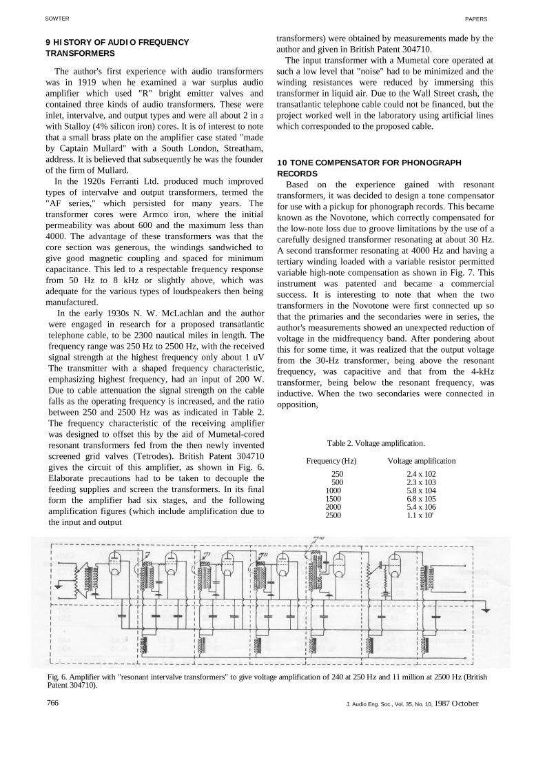
In the early 1930s N. W. McLachlan and the authorwere engaged in research for a proposed transatlantictelephone cable, to be 2300 nautical miles in length. Thefrequency range was 250 Hz to 2500 Hz, with the receivedsignal strength at the highest frequency only about 1 uVThe transmitter with a shaped frequency characteristic,emphasizing highest frequency, had an input of 200 W.Due to cable attenuation the signal strength on the cablefalls as the operating frequency is increased, and the ratiobetween 250 and 2500 Hz was as indicated in Table 2.The frequency characteristic of the receiving amplifierwas designed to offset this by the aid of Mumetal-coredresonant transformers fed from the then newly inventedscreened grid valves (Tetrodes). British Patent 304710gives the circuit of this amplifier, as shown in Fig. 6.Elaborate precautions had to be taken to decouple thefeeding supplies and screen the transformers. In its finalform the amplifier had six stages, and the followingamplification figures (which include amplification due tothe input and output
PAPERS
transformers) were obtained by measurements made by theauthor and given in British Patent 304710.
The input transformer with a Mumetal core operated atsuch a low level that "noise" had to be minimized and thewinding resistances were reduced by immersing thistransformer in liquid air. Due to the Wall Street crash, thetransatlantic telephone cable could not be financed, but theproject worked well in the laboratory using artificial lineswhich corresponded to the proposed cable.
10 TONE COMPENSATOR FOR PHONOGRAPHRECORDS
Based on the experience gained with resonanttransformers, it was decided to design a tone compensatorfor use with a pickup for phonograph records. This becameknown as the Novotone, which correctly compensated forthe low-note loss due to groove limitations by the use of acarefully designed transformer resonating at about 30 Hz.A second transformer resonating at 4000 Hz and having atertiary winding loaded with a variable resistor permittedvariable high-note compensation as shown in Fig. 7. Thisinstrument was patented and became a commercialsuccess. It is interesting to note that when the twotransformers in the Novotone were first connected up sothat the primaries and the secondaries were in series, theauthor's measurements showed an unexpected reduction ofvoltage in the midfrequency band. After pondering aboutthis for some time, it was realized that the output voltagefrom the 30-Hz transformer, being above the resonantfrequency, was capacitive and that from the 4-kHztransformer, being below the resonant frequency, wasinductive. When the two secondaries were connected inopposition,
Table 2. Voltage amplification.
Frequency (Hz) Voltage amplification250500
1000150020002500
2.4 x 1022.3 x 1035.8 x 1046.8 x 1055.4 x 1061.1 x 10'
Fig. 6. Amplifier with "resonant intervalve transformers" to give voltage amplification of 240 at 250 Hz and 11 million at 2500 Hz (BritishPatent 304710).
766 J. Audio Eng. Soc., Vol. 35, No. 10, 1987 October

PAPE
the performance curve in Fig. 7 was achieved. It shouldperhaps be stated that to get the exact frequencycharacteristics of the resonant transformers, a considerableamount of research was required.
By the early 1930s, nickel-iron alloys such as Mumetal,Permalloy C, Radiometal, and others were firmly
SOFT MAGNETIC MATERIALS FOR AUDIO
established as materials for audio frequency transformers.A very large variety of sizes of laminations becameavailable and eventually led to the formation of acommittee which produced a document giving thepreferred types, particularly for government departments.Many of these sizes are still being manufactured.
Fig. 7. McLachlan Novotone compensator for electrical reproduction of disk records using resonant audio transformers
J. Audio Eng. Soc., Vol. 35, No. 10,

SOWT
During World War II, munitions and communicationsmade great demands on these high-permeabilitylaminations, but a few unusual types of transformers areworth mentioning. Thus the Royal Aircraft Establishmentat Farnborough was interested in determining the vibrationfrequencies and their amplitudes on the mainly woodenaeroplane, the Mosquito, specially designed to avoid radar.In conjunction with the De Havilland Company, whichbuilt Mosquitos, the author designed and manufacturedMumetal-cored transformers operating over the range 4 Hzto 1 kHz, which suited the R. A. E. program. Thetransformers handled the small voltages set up bynickel-chromium wire transducers glued to the vibratingparts and a six-channel amplifier-recorder was built.
After this, a similar demand arose from the Wellcomeresearch laboratories for transformers to operate over 4 Hzto 1 kHz or above for the encephalograph. This is a devicefor measuring the tiny voltages set up between electrodesgummed to the patient's head for the study of brain tumors.Today as many as nine electrodes can be utilized.
It is amusing to recall that the author was invited to thelaboratories to witness the first demonstration of theequipment utilizing an anesthetized dog, on the head ofwhich had been fixed electrodes feeding the amplifier anda recording oscilloscope. Rhythmic signals at lowfrequencies were being observed when the doctor in chargefacetiously asked the author, "Would you like to have yourbrains tested?" Fearing the worst, the author agreed andwas asked to observe the pattern on the screen when heworked out an elementary mathematical calculation. To hisastonishment he found that the record showed a burst ofvoltages during the calculation, which was immediatelyfollowed by a second similar burst. He was told thatsubconsciously he checked his calculations although hewas unaware of this.
Another outstanding device considered during the warwas modified transformers for the Asdic antisubmarineequipment. Toward 1945 the author was also asked toredesign the normal transformers so that, without loss ofperformance, they could be appreciably reduced in size.
After the war ended in 1945 there began improvementsin recording on disks and tapes and a frequency rangespectrum of 40 Hz to 16 kHz became common, althoughsome recording companies specified 20 Hz to 20 kHz,which is normal for many transformers today.
Harmonic generation, today called distortion, then hadbecome important, and the author made a detailed studyof the properties of the nickel-iron alloys from this aspect.For this he was awarded an external Ph.D. by LondonUniversity, his thesis being entitled "Harmonic Distortionin Transformers and Chokes with Nickel Iron Cores" [8].The superiority of Mumetal over other alloys with respectto low distortion was studied and distortion coefficientswere evolved. These enabled designers to predicttransformer distortion on finished transformers, providedthe associated circuit
768
PAPE
parameters were disclosed. In the thesis the importance ofuniform flux density throughout the magnetic circuit wasshown to be essential if distortion is to be minimized. Fig.8 illustrates the distortion coefficients of various magneticmaterials in the form of interleaved assemblies oflaminations. These coefficients are directly proportional tothe resulting distortion, and the superiority of Mumetal isapparent. Fig. 9 gives the distortion coefficients forMumetal in forms other than laminations and emphasizesthe low distortion of highpermeability spiral cores.11 MAGNETIC CORES FOR AUDIOFREQUENCY TRANSFORMERS
The desirable properties for audio frequency magneticcores varies somewhat according to the type oftransformer. For those handling voltages over a widefrequency band, particularly starting at 20 Hz,highpermeability cores are essential to restrict the numberof turns and keep the leakage inductance down. Highresistivity of the magnetic material and low hysteresis andeddy current loss are desirable so that overall core lossesare minimized. Where actual power handling is small andlow cost is desirable, Mumetal 0.38 mm thick is mostlyemployed, although thinner laminations can offer certainadvantages, especially as regards permeability. This isparticularly the case for very small transformers requiredfor printed circuit board mounting. For this the range oflaminations available is somewhat limited but can vary insize from about 10 mm 2 up to a few square centimeters.On the Continent DIN standard sizes exist. Fig. 10 gives afew of the lamination sizes in general use, although forhigh per
Fig. 8. Distortion coefficients of various magnetic materials in theform of interleaved assemblies of laminations.
J. Audio Eng. Soc., Vol. 35, No. 10,

PAPERS
performance or appreciable audio output larger sizes areavailable.
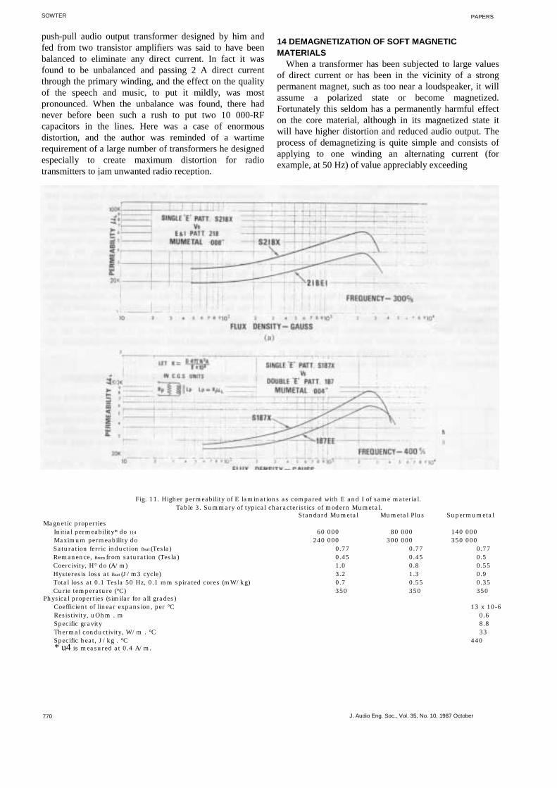
Laminations are generally in the form of Es and Is (tomake up a rectangular form) or Ts and Us, and care mustbe taken in assembly to avoid excess compression orbending since the permeability is easily reduced thereby.There are advantages in higher permeability by usingsingle E laminations (Fig. 11). Impregnation can haveundesired effects, and immersion in incorrect grades ofwax can lead to microphony, that is, minor voltages set upin the windings generally due to relative movements-ofwindings and cores.
It will be noticed that generally the core sectional areasare such that uniform flux density throughout the magneticcircuit is obtained. This is most important to minimizeharmonic generation, and the presence of holes for boltsfor fixing purposes does cause nonuniform fluxconcentration. Laminations are normally interleaved toform a stack, but when this is the case, a strikingphenomenon is observed.
Referring to Table 3, which gives the latest properties ofthe various grades of Mumetal, it will be observed that thesaturation flux density is 0.77 T. Now by examining themanufacturers' curves for Mumetal laminations type 187(Fig. 12) it will be seen that the permeability falls rapidlybeyond 0.3 T, or less than half of the ferric inductionsaturation. This obviously limits the practical maximuminduction at which the transformer can operate since highdistortion starts at this density. Fig. 13 shows the widerange of permeabilities
SOFT MAGNETIC MATERIALS FOR AUDIO TRANSFORMERS
found over a number of batches of laminations, as sold,which shows initial permeability varying from 16 000 to27 000 and a comparable divergence over the whole usefulrange of flux density. This must be taken into accountwhen designing. The reason for the limitation of maximumworking induction is given in detail in [9], from whichFigs. 14 and 15 are taken. Basically it is due to thecrowding of flux at the imbricated joints in the laminationassembly, which is discussed in detail in this paper.
12 DISTORTION IN AUDIO TRANSFORMERS
Referring to Figs. 8 and 9 it will be noticed thatdistortion increases as the flux density is raised so thatwherever there are flux concentrations, additionaldistortion is produced. With an audio transformer thehighest operating flux levels are at the lowest frequency,and here the maximum distortion occurs. As frequency israised, for a definite operating voltage, the flux isprogressively reduced so that harmonic generation falls.For the higher frequencies in the audio range there is the"skin effect," that is, the flux tends to concentrate on theouter surface of the laminations, which accounts for thefall in effective permeability, as shown in Fig. 16.Obviously for best operation at high audio frequenciesthin material, such as 0.1 mm thick, has advantages asregards both inductance and distortion, but it is expensive.
13 INCREMENTAL OPERATING CONDITIONS
The passage of direct current through winding carryingaudio, frequency currents causes magnetization whichresults in a severe diminution in permeability and limitsthe audio output. This is of particular importance withtransistor amplifiers where heavy direct current can beavailable in the output.
In one case encountered by the author a 300-VA
Fig. 9. Distortion coefficients of Mumetal. O-cut ringstampings with interleaved joints; x-ring-stampings; 0- Fig. 10. Sizes and types of some of the laminations used forspiral core; A-high-permeability spiral core. audio frequency transformers.
J. Audio Eng. Soc., Vol. 35, No. 10, 1987 October 769
SOWTER
push-pull audio output transformer designed by him andfed from two transistor amplifiers was said to have beenbalanced to eliminate any direct current. In fact it wasfound to be unbalanced and passing 2 A direct currentthrough the primary winding, and the effect on the qualityof the speech and music, to put it mildly, was mostpronounced. When the unbalance was found, there hadnever before been such a rush to put two 10 000-RFcapacitors in the lines. Here was a case of enormousdistortion, and the author was reminded of a wartimerequirement of a large number of transformers he designedespecially to create maximum distortion for radiotransmitters to jam unwanted radio reception.
PAPERS
14 DEMAGNETIZATION OF SOFT MAGNETICMATERIALS
When a transformer has been subjected to large valuesof direct current or has been in the vicinity of a strongpermanent magnet, such as too near a loudspeaker, it willassume a polarized state or become magnetized.Fortunately this seldom has a permanently harmful effecton the core material, although in its magnetized state itwill have higher distortion and reduced audio output. Theprocess of demagnetizing is quite simple and consists ofapplying to one winding an alternating current (forexample, at 50 Hz) of value appreciably exceeding
770 J. Audio Eng. Soc., Vol. 35, No. 10, 1987 October
Fig. 11. Higher permeability of E laminations as compared with E and I of same material.Table 3. Summary of typical characteristics of modern Mumetal.
Standard Mumetal Mumetal Plus SupermumetalMagnetic properties
Initial permeability* do 114 60 000 80 000 140 000Maximum permeability do 240 000 300 000 350 000Saturation ferric induction Bsat (Tesla) 0.77 0.77 0.77Remanence, Brem from saturation (Tesla) 0.45 0.45 0.5Coercivity, H° do (A/m) 1.0 0.8 0.55Hysteresis loss at Bsat (J/m3 cycle) 3.2 1.3 0.9Total loss at 0.1 Tesla 50 Hz, 0.1 mm spirated cores (mW/kg) 0.7 0.55 0.35Curie temperature (°C) 350 350 350
Physical properties (similar for all grades)Coefficient of linear expansion, per °C 13 x 10-6Resistivity, uOhm . m 0.6Specific gravity 8.8Thermal conductivity, W/m . °C 33Specific heat, J/kg . °C 440* u4 is measured at 0.4 A/m.

PAPERS SOFT MAGNETIC MATERIALS FOR AUDIO TRANSFORMERS
Fig. 14. Variation of permeability of interleaved laminations with flux density as compared with butted and gapped assemblies. 0-interleave0-butted; O-with 0.001-in gap in one outer limb and butt joint in the other; x -with 0.001-in gap in middle and in both outer limbs. Notechange of scale of ordinate at [L5-5000.
J. Audio Eng. Soc., Vol. 35, No. 10, 1987 October 771

SOWTER
that required for saturation. This current should then bereduced smoothly and gradually over a period of time,such as one-half to one minute. In its most elementaryform this can be done with a suitable variable resistance,such as a potential divider capable of handling the largecurrent. It is important to spend the bulk of the time on thelow values of demagnetizing force, which should bereduced to absolute zero. Another demagnetizing methodis to reverse direct current continuously while reducing itsvalue to zero. It should be stressed that Mumetal does noteasily acquire unidirectional magnetization under normaloperating conditions. Silicon iron, however, can becomepolarized to a small extent if low-frequency ac signals orpulses of values approaching saturation are encountered,and this increases distortion.
15 HISTORY OF MAGNETIC SHIELDING AS USEDFOR AUDIO TRANSFORMERS
Nowadays a good proportion of audio transformers arecontained in high-permeability (usually Mumetal)magnetic shielding cans where 50-Hz "hum" may exist,and these are most effective.
The first evidence of magnetic shielding was in the
Fig. 15. Variation of permeability with flux density of Mumetalspiral cores showing higher possible working densities.x-high-permeability specimen; O-medium-permeability specimen;A-low-permeability specimen.
PAPERS
early 1820s, when it was demonstrated that a horseshoepermanent magnet freely suspended and rotated over acopper disk caused the latter to rotate. (This is theprinciple of the induction motor.) By interfacing variousnonferrous disks between the magnet and the copper diskthere was little effect. When, however, an iron disk wasinterfaced, the copper disk did not move, and this was thefirst evidence of magnetic shielding. Other metals thancopper were tried instead for the rotatable disk, and it wasfound that silver was comparable but bismuth reacted veryweakly. It is now known that electric conductivity is thedesideratum for motion of the disk.
On 1883 November 8 Willoughby Smith, as presidentof the Society of Telegraph Engineers and Electricians,read a paper entitled "Volta-Electrical Induction" [10].This society became the present Institution of ElectricalEngineers (IEE) some years later in 1888.
For demonstration purposes he utilized two woodenframes about 36 in 2 in which were supported flat helicesof insulated copper wire, as indicated in Fig. 17. The coilswere placed some distance apart, and switches D and Ewere mechanically controlled and could be synchronized.
Faraday had also experimented with similar coils withhand-operated static switches as in Fig. 17(b) and foundthat when the space between the coils was filled withinsulating bodies such as sulfur and shellac, there was noeffect on the galvanometer deflection when the circuitwas made or broken. Copper and other nonmagneticmaterials also had no observable effect, and WilloughbySmith wrote:
It is to be regretted that so sound a reasoner and so carefulan experimenter had not the great advantage of the assistance ofsuch suitable instruments for this class of research as theMirror-Galvanometer and the Telephone.
It is noteworthy that both these instruments wereavailable in 1879, Sir William Thomson's mirror re-flecting galvanometer being described in detail by Wil-loughby Smith in his paper read before the Society ofTelegraph Engineers on 1879 February 12 [11].
In his presidential paper Willoughby Smith was able tosend interrupted current through coil A and measure theinduced currents in coil B at various frequencies.
Fig. 16. Curves stressing fall in permeability with increasing frequency and showing advantage of thin laminations.
772 J. Audio Eng. SOC., Vol. 35, No. 10, 1987 October

PAPERS
The results of his tests by placing between the coils sheetsof copper, zinc, tin, iron, and lead show wide differencesin shielding effects and particularly variations as thefrequency increased. (This author found all this equipmentsome 40 years later in his company's stores.)
A more scientific series of shielding tests was carriedout by Constable and Aston at the National PhysicalLaboratory some 40 years ago, and results are given inTable 4. It will be noted that at 50 Hz Mumetal is easilythe most effective, but while copper 1/32 in thick has a valueof 4 dB at 50 Hz it becomes 26 dB at 3200 Hz.
With the passage of time and research on the effects ofimpurities in Mumetal, the permeabilities have greatlyimproved, and comparatively thinner thicknesses forshields are employed. It is even possible to obtain
SOFT MAGNETIC MATERIALS FOR AUDIO TRANSFORMERS
some degree of shielding by wrapping a transformer invery thin Mumetal tape, 0.05 or 0.1 mm thick, but the usesare limited.
For shielding audio frequency transformers the author,in the 1930s, devised about 10 deep-drawn cylindricalMumetal cans, and many of these sizes have persisted upto the present time. The normal reduction in hum by theuse of these cans is 30-40 dB, but where 50-Hz fields areintense, it is customary to use double shields or even aMumetal shield encased in a second shield having a highersaturation induction, such as Radiometal 50% Ni-50% Fealloy.
When low- and high-frequency audio fields are to beminimized it is possible to copper plate Mumetal shields,although an inner lining of copper foil is preferable.
The usual method of measuring hum reduction is to
Fig. 17. Magnetic shielding measurements by Willoughby Smith in 1882.
Table 4. Screening effects of various materials compared with Mumetal.
J. Audio Eng. Soc., Vol. 35, No. 10, 1987 October 773
SOWT
create a uniform 50-Hz magnetic field by the use ofHelmholtz coils and to measure the voltage setup in atransformer first without a shield, then when encased in ashield.
For some applications, particularly for electromedicalpurposes or electron-microscope observations or where theearth's field is to be minimized or eliminated, it is possibleto line a room with a Mumetal sheet, or even to make aMumetal cabin capable of housing an operator.
16 SOME NOTES ON FREQUENCY RESPONSEOF AUDIO TRANSFORMERS
The lower register of the frequency response is obtainedby the correct selection of the grade and size of themagnetic core and by the number of primary turns. Themaximum operating flux density must be chosen to keepwithin the acceptable distortion range, and this generally isquite a straightforward procedure.
The middle register up to about 10 kHz will generallybe acceptable with the above provisos for the bass,provided that the copper and iron losses are not excessive.
The top register from, say, 10 kHz to 20 kHzdepends
PAPE
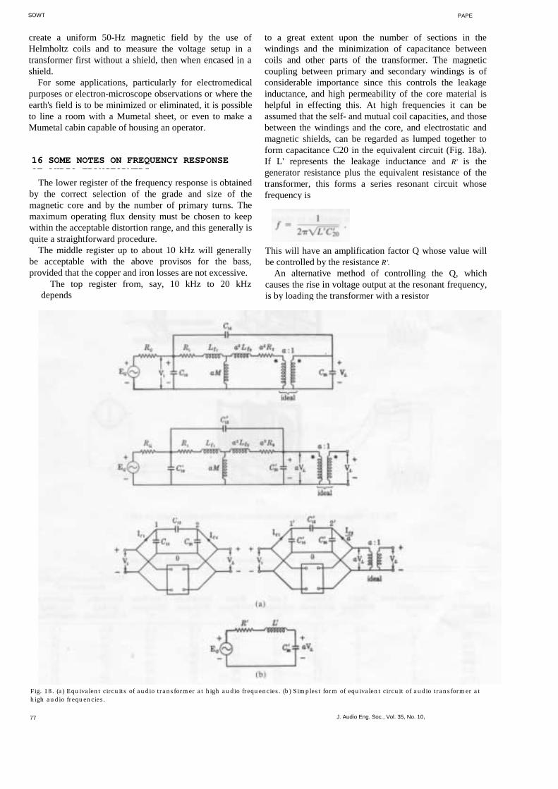
to a great extent upon the number of sections in thewindings and the minimization of capacitance betweencoils and other parts of the transformer. The magneticcoupling between primary and secondary windings is ofconsiderable importance since this controls the leakageinductance, and high permeability of the core material ishelpful in effecting this. At high frequencies it can beassumed that the self- and mutual coil capacities, and thosebetween the windings and the core, and electrostatic andmagnetic shields, can be regarded as lumped together toform capacitance C20 in the equivalent circuit (Fig. 18a).If L' represents the leakage inductance and R' is thegenerator resistance plus the equivalent resistance of thetransformer, this forms a series resonant circuit whosefrequency is
This will have an amplification factor Q whose value willbe controlled by the resistance R'.
An alternative method of controlling the Q, whichcauses the rise in voltage output at the resonant frequency,is by loading the transformer with a resistor
Fig. 18. (a) Equivalent circuits of audio transformer at high audio frequencies. (b) Simplest form of equivalent circuit of audio transformer athigh audio frequencies.
77 J. Audio Eng. Soc., Vol. 35, No. 10,
PAPERS
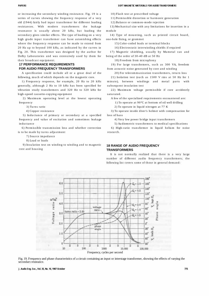
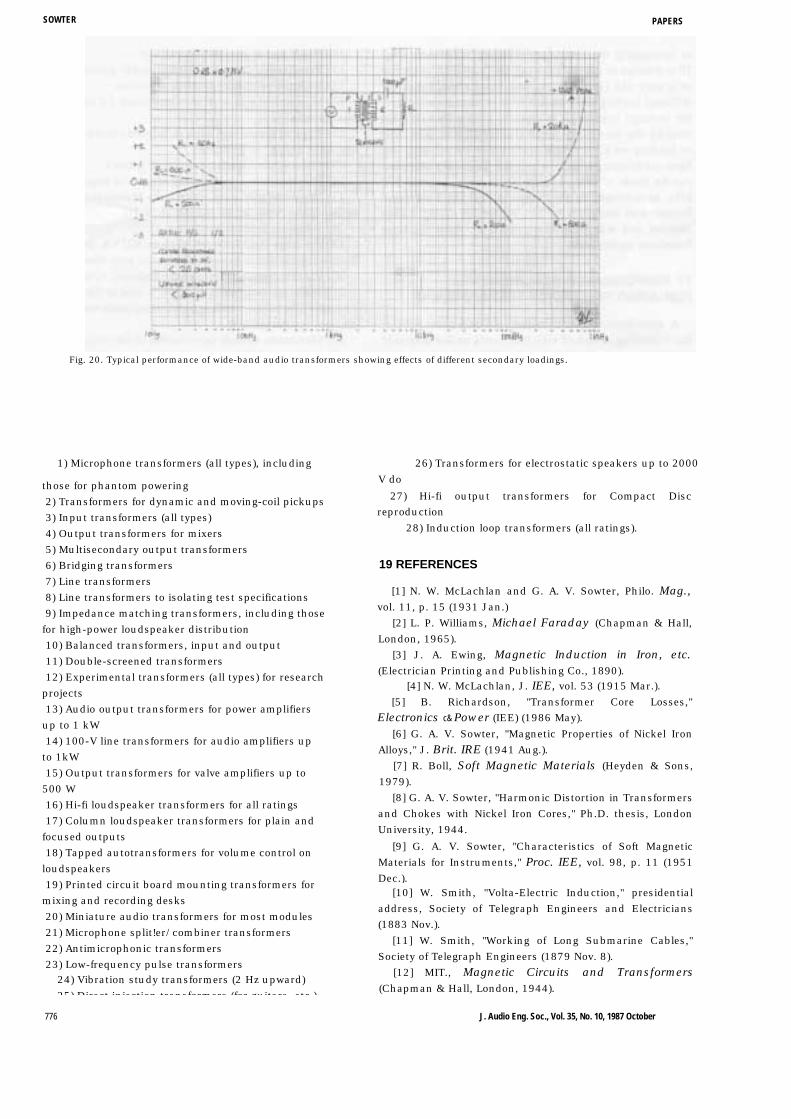
or increasing the secondary winding resistance. Fig. 19 is aseries of curves showing the frequency response of a veryold (1944) fairly bad input transformer for different loadingresistances. With modern transformers the leakageresonance is usually above 20 kHz, but loading thesecondary gives similar effects. The type of loading on a veryhigh grade input transformer can have astonishing effectswhere the frequency response can be made to extend from20 Hz up to beyond 100 kHz, as indicated by the curves inFig. 20. This transformer was designed by the author forDolby Laboratories and was extensively used by them fortheir broadcast equipment.17 PERFORMANCE REQUIREMENTSFOR AUDIO FREQUENCY TRANSFORMERS
A specification could include all or a great deal of thefollowing, much of which depends on the magnetic core.
1) Frequency response, for example, 20 Hz to 20 kHzgenerally, although 2 Hz to 10 kHz has been specified forvibration study transformers and 320 Hz to 320 kHz forhigh-speed cassette-copying equipment
2) Maximum operating level at the lowest operatingfrequency
3) Turns ratio4) Copper resistance
5) Inductance of primary or secondary at a specifiedfrequency and value of excitation and sometimes leakageinductance
6) Permissible transmission loss and whether correctionis to be made by turns adjustment
7) Source impedance8) Load or loads
9) Insulation test on winding to winding and to magneticcore and housing
SOFT MAGNETIC MATERIALS FOR AUDIO TRANSFORMERS
10) Flash test at prescribed voltage11) Permissible distortion or harmonic generation12) Balance or common-mode rejection13) Mechanical size with any limitations for insertion in a
module14) Type of mounting, such as printed circuit board,
one-hole fixing, or grommet15) Color-coded leads or terminal blocks16) Electrostatic interwinding shields if required
17) Magnetic shielding, usually by Mumetal can andbeing of the order of 30-40 dB at 50 Hz
18) Freedom from microphony19) For large transformers, such as 300 VA, freedom
from acoustic noise generated by core and winding20) For telecommunication transformers, return loss
21) Isolation test (such as 1500 V rms at 50 Hz for 1minute), between windings and metal parts withsubsequent insulation test
22) Maximum voltage permissible if core accidentlysaturated.
A few of the specialized requirements encountered are:1) To operate at 90°C at bottom of oil well drilling2) To operate in liquid nitrogen at 77 K
3) To operate inside diver's helmet with compensation forloss of bass
4) Very low power bridge input transformers5) Audiometric transformers to medical specifications
6) High-ratio transformer in liquid helium for noiseresearch.
18 RANGE OF AUDIO FREQUENCYTRANSFORMERS
It is not normally realized that there is a very largenumber of different audio frequency transformers; thefollowing list covers some of those in general demand:
Frequency, cycles per second
Fig. 19. Frequency and phase characteristics of a circuit containing an input or interstage transformer, showing the effects of varying thesecondary resistance.
J. Audio Eng. Soc., Vol. 35, No. 10, 1987 October 775
SOWTER PAPERS
Fig. 20. Typical performance of wide-band audio transformers showing effects of different secondary loadings.
1) Microphone transformers (all types), including 26) Transformers for electrostatic speakers up to 2000
those for phantom powering2) Transformers for dynamic and moving-coil pickups3) Input transformers (all types)4) Output transformers for mixers5) Multisecondary output transformers6) Bridging transformers7) Line transformers8) Line transformers to isolating test specifications9) Impedance matching transformers, including thosefor high-power loudspeaker distribution10) Balanced transformers, input and output11) Double-screened transformers12) Experimental transformers (all types) for researchprojects13) Audio output transformers for power amplifiersup to 1 kW14) 100-V line transformers for audio amplifiers upto 1kW15) Output transformers for valve amplifiers up to500 W16) Hi-fi loudspeaker transformers for all ratings17) Column loudspeaker transformers for plain andfocused outputs18) Tapped autotransformers for volume control onloudspeakers19) Printed circuit board mounting transformers formixing and recording desks20) Miniature audio transformers for most modules21) Microphone split!er/combiner transformers22) Antimicrophonic transformers23) Low-frequency pulse transformers
24) Vibration study transformers (2 Hz upward)25) Direct injection transformers (for guitars etc )
776
V do27) Hi-fi output transformers for Compact Disc
reproduction28) Induction loop transformers (all ratings).
19 REFERENCES
[1] N. W. McLachlan and G. A. V. Sowter, Philo. Mag.,vol. 11, p. 15 (1931 Jan.)
[2] L. P. Williams, Michael Faraday (Chapman & Hall,London, 1965).
[3] J. A. Ewing, Magnetic Induction in Iron, etc.(Electrician Printing and Publishing Co., 1890).
[4] N. W. McLachlan, J. IEE, vol. 53 (1915 Mar.).[5] B. Richardson, "Transformer Core Losses,"
Electronics c& Power (IEE) (1986 May).[6] G. A. V. Sowter, "Magnetic Properties of Nickel Iron
Alloys," J. Brit. IRE (1941 Aug.).[7] R. Boll, Soft Magnetic Materials (Heyden & Sons,
1979).[8] G. A. V. Sowter, "Harmonic Distortion in Transformers
and Chokes with Nickel Iron Cores," Ph.D. thesis, LondonUniversity, 1944.
[9] G. A. V. Sowter, "Characteristics of Soft MagneticMaterials for Instruments," Proc. IEE, vol. 98, p. 11 (1951Dec.).
[10] W. Smith, "Volta-Electric Induction," presidentialaddress, Society of Telegraph Engineers and Electricians(1883 Nov.).
[11] W. Smith, "Working of Long Submarine Cables,"Society of Telegraph Engineers (1879 Nov. 8).
[12] MIT., Magnetic Circuits and Transformers(Chapman & Hall, London, 1944).
J. Audio Eng. Soc., Vol. 35, No. 10, 1987 October

PAPERS SOFT MAGNETIC MATERIALS FOR AUDIO TRANSFORMERS
THE AUTHOR
G. A. V. Sowter was born in London, U.K., and educatedat London University, where he was awarded his B.Sc. inengineering in 1922. He then joined the TelegraphConstruction and Maintenance Co., which made and laid thefirst Atlantic submarine cable, and he was engaged inresearch on magnetic materials. This included the early workand evolution on Mumetal and kindred alloys by the team. Inthe early 1930s, he worked with N. W. McLachlan, thecelebrated pioneer of moving-coil loudspeaker research, anddeveloped a transmitter and receiver for a projectedtransatlantic telephone submarine cable. The economicworld depression of the 1930s terminated this project andlaboratory work on moving coil loudspeakers wasundertaken.
A number of technical papers were published by Dr.Sowter and Dr. McLachlan on loudspeaker articles in thePhilosophical Magazine. During this period the standardtextbook Loudspeakers by N. W. McLachlan was published,based on the extensive measurements carried on by Dr.Sowter. Dr. Sowter became chairman of the measurementsdivision of the Institution of Electrical Engineers, was onthe council for a number of years, and served on many oftheir committees. He received a fellowship of the I.E.E.Previously he had been Chairman of the Council of theBritish Institution of Radio Engineers (now I.E.E.I.E.) andstill enjoys his ham radio-his callsign G20S being allocatedin the early 20s. He has chaired a number of BritishStandard Committees on magnetic materials and has writtenseveral technical papers on this subject. He became GroupCommercial Director of several Telcon Metals companieswhich included factories producing Mumetal
and other alloys.Prior to World War II Dr. Sowter spent several years
teaching at Higher National Certificate level as well asmanaging Telcon Metals Ltd. This resulted in the award ofan external Ph.D. degree at London University, where histhesis was on "Harmonic Distortion in Transformers andChokes with Nickel Iron Cores."
In the late 1930s he became consultant to SowterTransformers, Ipswich, U.K., which produces every type ofaudio frequency transformer. He is still active in this capacityand has made hundreds of designs resulting in the sale ofthousands of transformers handling from a few microwattsup to a kilowatt. His expertise in the properties andapplications of high-permeability magnetic alloys led to thedesign of transformers for the Royal Shakespeare Co.Barbican, Royal Opera House Covent Garden, BBC Studios,Dolby Laboratories, plus many others.
Dr. Sowter has traveled extensively, including a visit toChina 25 years ago. He is treasurer and member of the"Dynamicables" Club, which has celebrated its Centenaryrecently and consists of the 100 outstanding British ElectricalEngineers.
He is also a registered chartered engineer by the BritishEngineering Council. At the 73rd Convention of the AudioEngineering Society in Eindhoven, Dr. Sowter was awardeda fellowship in recognition of his achievements in the audiofield. The citation, approved by Ray Dolby, chairman of theAES Awards Committee, reads: "For contributions to audiotransformer and loudspeaker design, particularly the optimalemployment of magnetic materials."
J. Audio Eng. Soc., Vol. 35, No. 10, 1987 October 777