soec and battery materials - dtu fysik
TRANSCRIPT

Highlight word(s) in header by changing the font to Open Sans (Headings) + Bold Insert a background picture by clicking on the Insert frontpage picture-button placed in Haldor Topsøe-menu
Highlight word(s) in header by
changing the font to Open Sans
(Headings) + Bold
1
Søren Dahl, Electrochemisty R&D, Haldor Topsoe
CINF Summer School 2016 - Reactivity of nanoparticles for more efficient and sustainable energy conversion - IV
Electrochemistry at Haldor Topsøe SOEC and Battery Materials

2
Agenda
• Electrochemistry at Haldor Topsoe
• Solid Oxide Electrolysis Cells • Optimal integration in the Energy system
• Battery materials • Automotive batteries for the next 10 years • Na-ion: Layered structure • Li-ion: High voltage spinel

3
More wind and solar power – a challenge to balance
A need for technologies to balance fluctuating wind and solar power
§ International integration of energy systems
§ Integration with gas, heat and transport
§ Storage
4
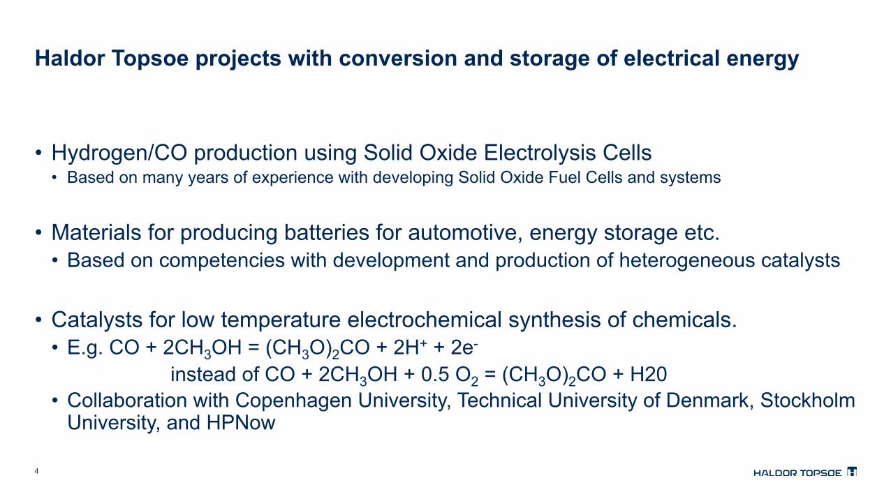
Haldor Topsoe projects with conversion and storage of electrical energy
• Hydrogen/CO production using Solid Oxide Electrolysis Cells • Based on many years of experience with developing Solid Oxide Fuel Cells and systems
• Materials for producing batteries for automotive, energy storage etc. • Based on competencies with development and production of heterogeneous catalysts
• Catalysts for low temperature electrochemical synthesis of chemicals. • E.g. CO + 2CH3OH = (CH3O)2CO + 2H+ + 2e- instead of CO + 2CH3OH + 0.5 O2 = (CH3O)2CO + H20 • Collaboration with Copenhagen University, Technical University of Denmark, Stockholm
University, and HPNow

5
Optimal integration in the Energy system Solid Oxide Electrolysis Cells
6
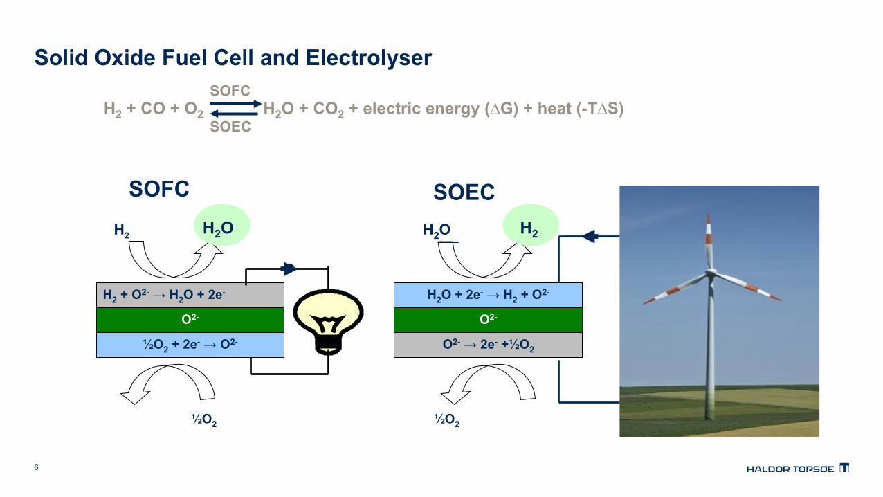
Solid Oxide Fuel Cell and Electrolyser
½O2
H2 H2O
½O2
H2O + 2e- → H2 + O2- O2-
O2- → 2e- +½O2
H2 + O2- → H2O + 2e- O2-
½O2 + 2e- → O2-
SOFC SOEC H2 H2O
H2 + CO + O2 H2O + CO2 + electric energy (∆G) + heat (-T∆S) SOFC
SOEC

7
Solid Oxide Cell Development from 1989 to 2013
Cell generations with ceramic support
3G metallic support
Ni/YSZ
YSZ LSM
YSZ or SSZ Ni/YSZ
CGO LSCF
LSCF CGO
YSZ or SSZ FeCr
850 oC 600 oC 750 oC 1000 oC
Ni/YSZ
YSZ
LSM
1G 2.XG 2.5G
Performance– Robustness – Cost reduction
ESC
ASC MSC

8
Electrolysis with SOEC Very flexible and efficient in continuous operation
CO H2 CO2
Power Steam CO2 Heat
Hydrogen SNG Methanol DME Gasoline Diesel
Syngas
Wel
l-kno
wn
Cat
alys
is
SO
EC
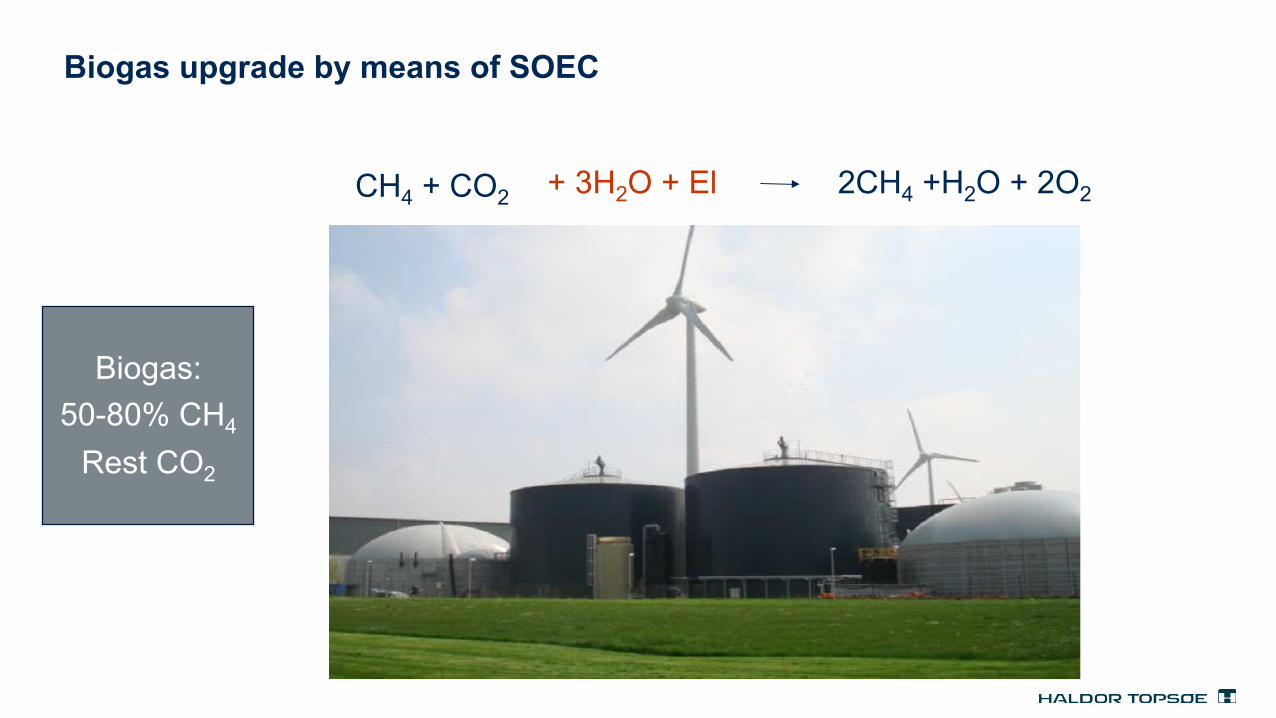
Biogas upgrade by means of SOEC
CH4 + CO2 + 3H2O + El 2CH4 +H2O + 2O2
Biogas: 50-80% CH4
Rest CO2

CO2 + 4H2 ↔ CH4 + 2H2O (-∆H = 165 kJ/mol)
Syngas = CH4 + heat
Energy: 100% = 80% + 20%
CH4 100% 80%
20% Heat
Methanation generates a lot of heat
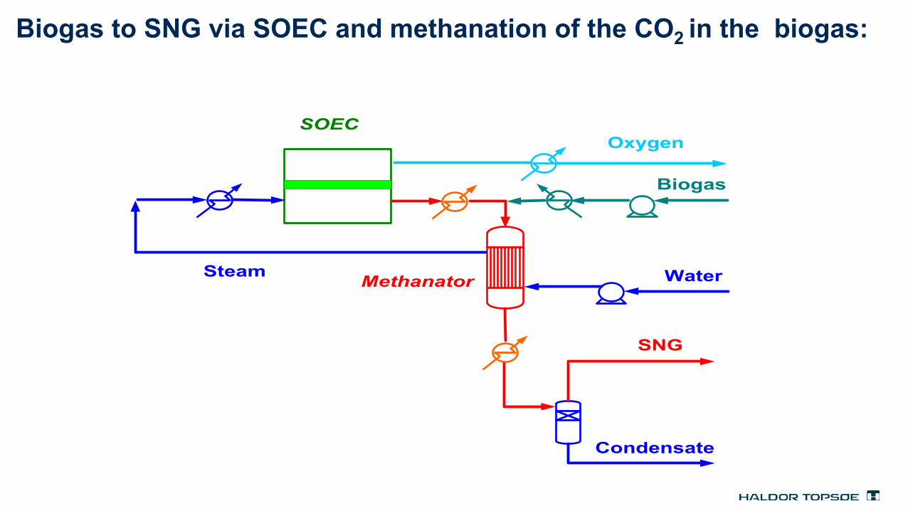
Biogas to SNG via SOEC and methanation of the CO2 in the biogas:
Biogas
Oxygen
Water
Condensate
SNG
Steam Methanator
SOEC

Exergy Flows in CO2 case

13
Idea : Biogas directly to CH4 via SOEC
Biogas
Oxygen
Water
Condensate
SNG
Steam
Methanator
SOEC
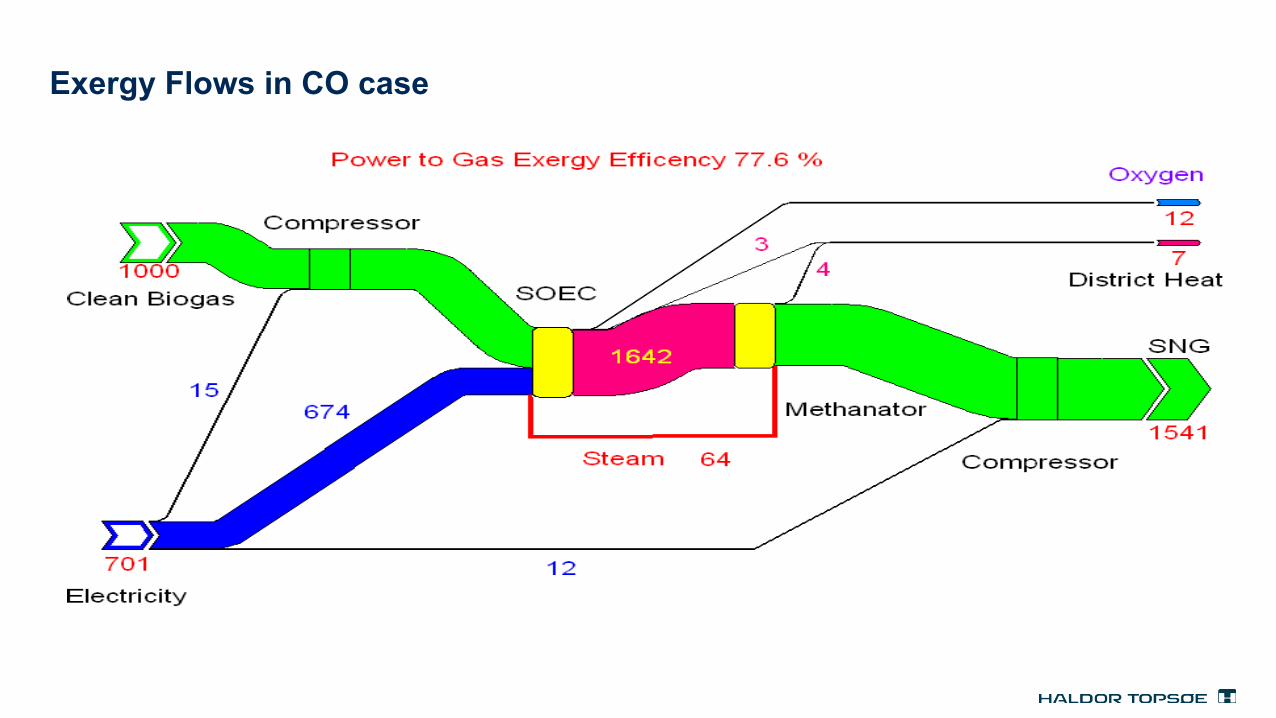
Exergy Flows in CO case
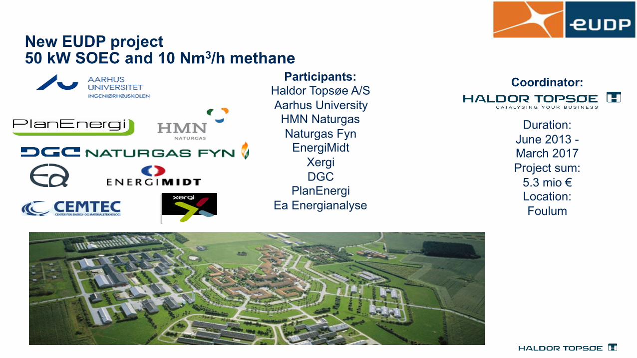
New EUDP project 50 kW SOEC and 10 Nm3/h methane
Participants: Haldor Topsøe A/S Aarhus University HMN Naturgas Naturgas Fyn
EnergiMidt Xergi DGC
PlanEnergi Ea Energianalyse
Coordinator:
Duration: June 2013 - March 2017 Project sum:
5.3 mio € Location: Foulum

16
Automotive batteries for the next 10 years Battery Materials
17
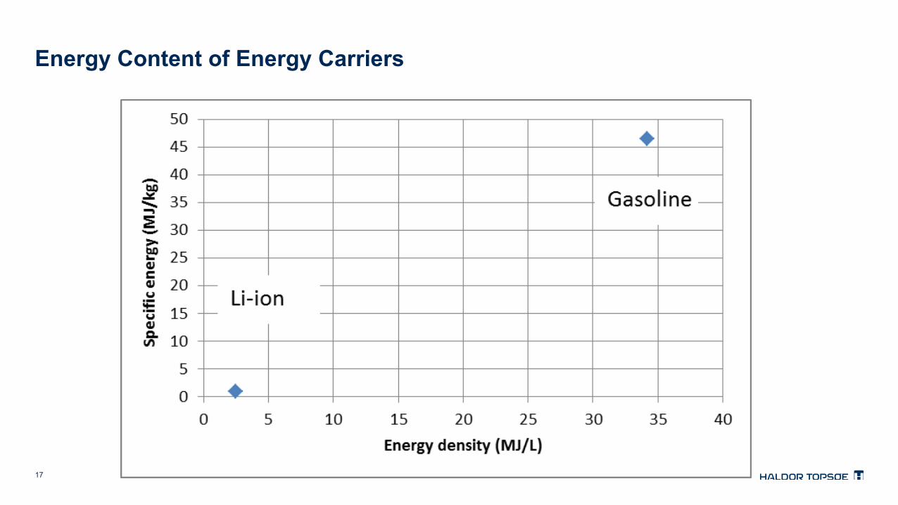
Energy Content of Energy Carriers

18
Batteries beyond Li-ion – Base on conversion materials Vo
ltage
[V] Mixed potential
Resistive loses
2.0
3.0
4.0
5.0
Capacity
e-
e-
Li+
O2
Li2O2Lithium-air battery

19
Energy Content of Energy Carriers
Planned to be used for a lot of BEVs in the next 10 years!

20
Li(Na)-ion - Batteries based on insertion materials
Electrolyte
Cathode Current collector Anode
Current collector
Anode
SEI-layer Separator Cathode
Li+
Charge
Li+ e- e-
Discharge
21
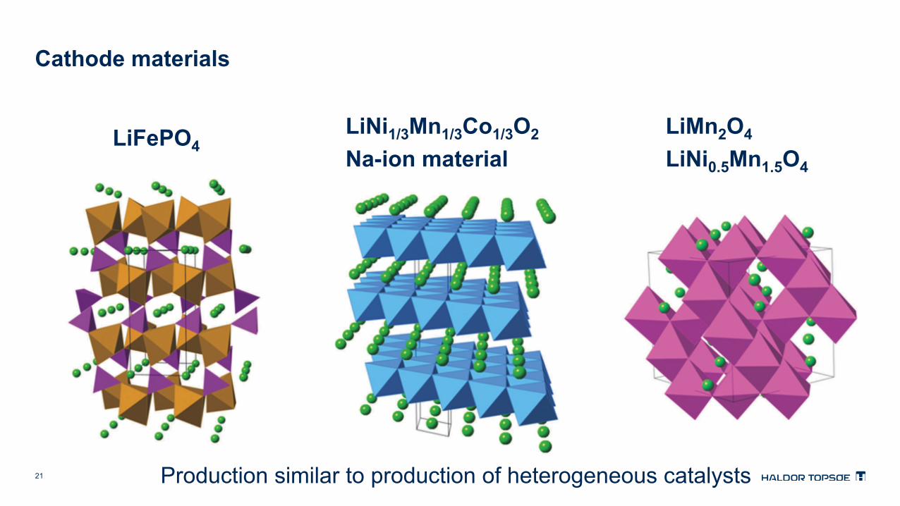
Cathode materials
LiFePO4 LiNi1/3Mn1/3Co1/3O2
Na-ion material LiMn2O4
LiNi0.5Mn1.5O4
Production similar to production of heterogeneous catalysts

22
Material properties – Battery performance
Material properties • Which material
• Metals, anions, structure • Phase purity • Crystal defects • Crystal size and shape • Secondary particles
• Connectivity between crystals • Porosity • Size and distribution
• Surface area • Doping/Contamination • Surface modification/coating
Battery performance • Energy density (mass/volume) • Power density • Price • Stability • Safety • ….. • ….
23
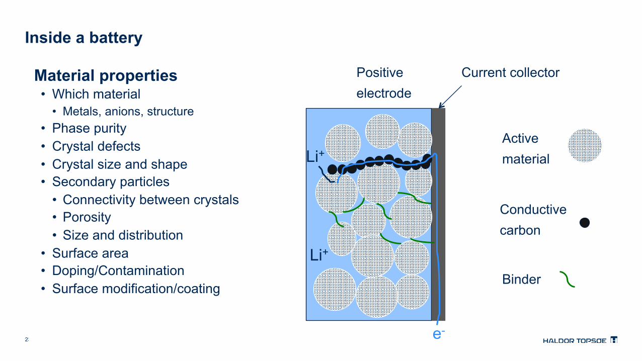
Inside a battery
Positive electrode
Neg
ativ
e el
ectro
de
Separator
Soaked in electrolyte
Positive electrode
Active material
Conductive carbon
Binder
Current collector
e-
Li+
Li+
Material properties • Which material
• Metals, anions, structure • Phase purity • Crystal defects • Crystal size and shape • Secondary particles
• Connectivity between crystals • Porosity • Size and distribution
• Surface area • Doping/Contamination • Surface modification/coating
24
Material properties – Battery performance
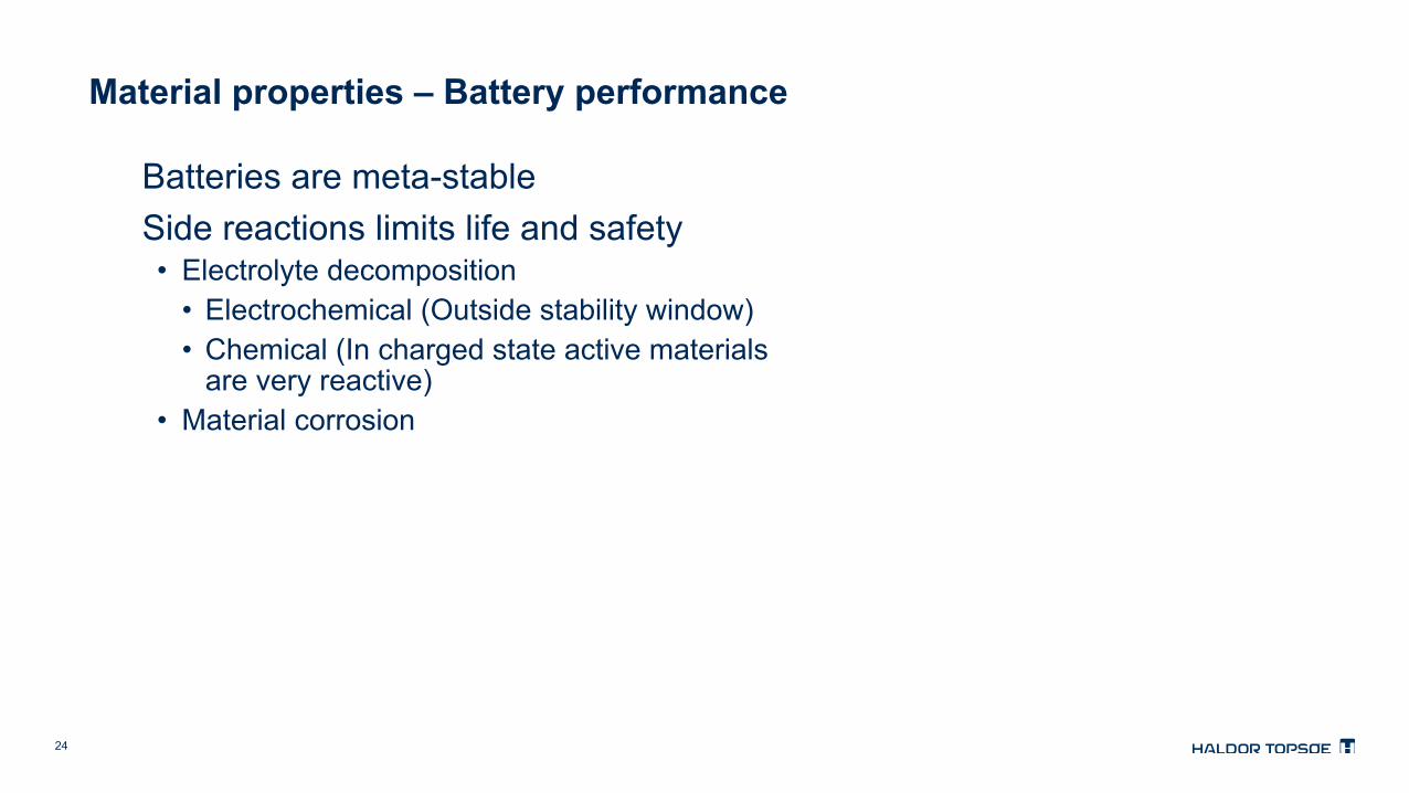
Batteries are meta-stable Side reactions limits life and safety • Electrolyte decomposition
• Electrochemical (Outside stability window) • Chemical (In charged state active materials
are very reactive) • Material corrosion

25
Material properties – Battery performance
Material properties • Which material
• Metals, anions, structure • Phase purity • Crystal defects • Crystal size and shape • Secondary particles
• Connectivity between crystals • Porosity • Size and distribution
• Larger surface area • Doping/Contamination • Surface modification/coating
Battery performance • Lower Energy density (mass/volume) • Better Power density • Higher price • Lower Stability • Less Safe • …. • ….
Trade-offs

Highlighted text is blue,
other text is white
Topsoes goal is to develop optimal battery materials with the optimal production processes

27
Where to focus? Materials
LiNi0.5Mn1.5O4
Li(Ni0.8Co0.1Mn0.1)O2
4.5 V 140 mAhg-1
3.6 V 210 mAhg-1
For Li-ion
Sodium
Sulfur
New technologies
e-
e-
Li+
O2
Li2O2
Lithium air
Li(Ni1/3Co1/3Mn1/3)O2
3.6 V 170 mAhg-1
28
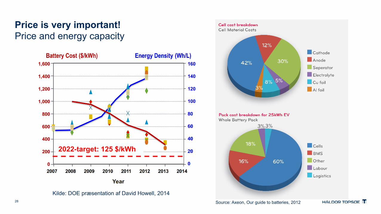
Price is very important! Price and energy capacity
David Howell Hybrid Electric Systems Program Manager, DOE http://www.ens.dk/sites/ens.dk/files/klima-co2/transport/elbiler/IA-HEV_EVI/Konference_22_maj_2014/david_howell_u.s._department_of_energy.pdf Competitive with gasoline in 2022: Target: $125/kWh (Currently 325) Electric drive: $5/kW
Kilde: DOE præsentation af David Howell, 2014
2022-target: 125 $/kWh
Source: Axeon, Our guide to batteries, 2012
29
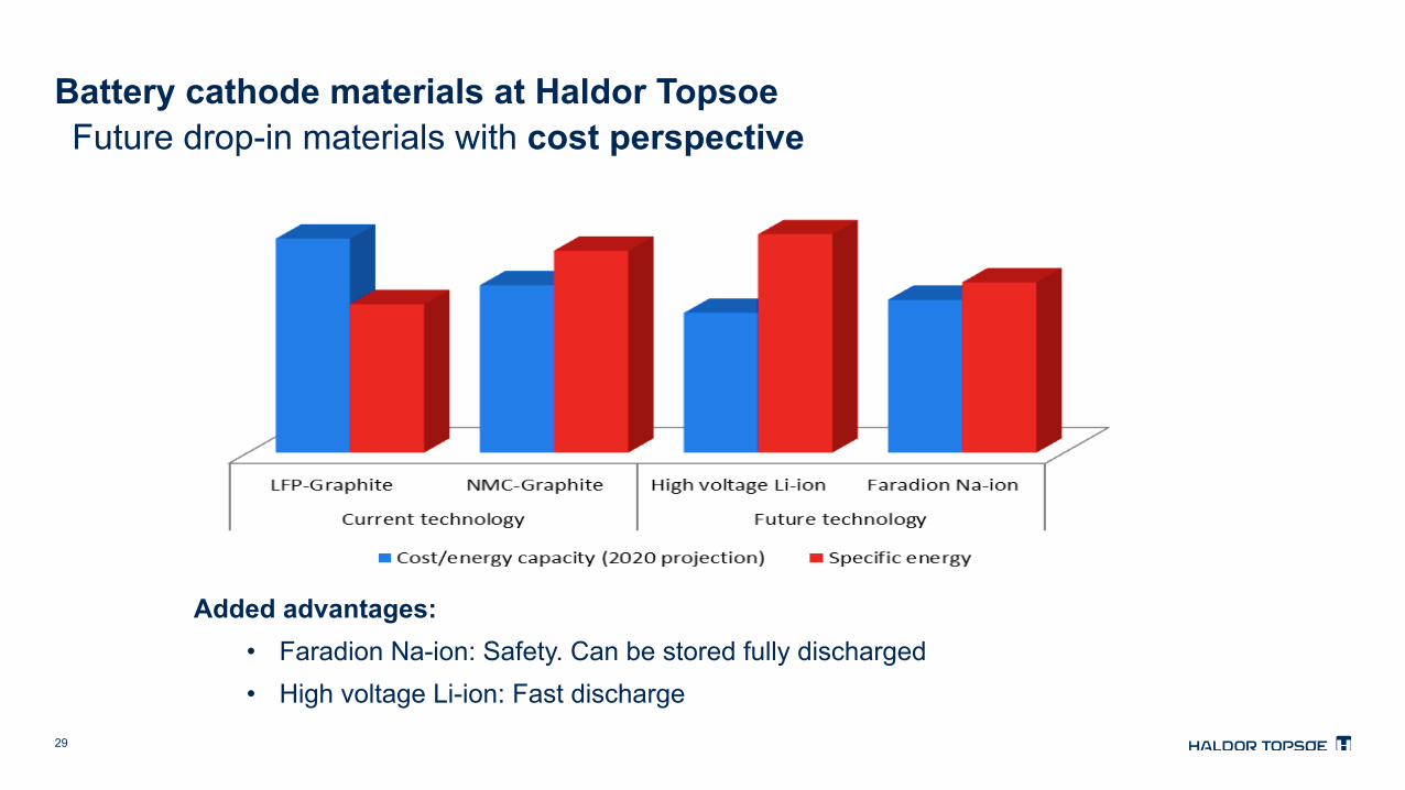
Battery cathode materials at Haldor Topsoe Future drop-in materials with cost perspective
Added advantages: • Faradion Na-ion: Safety. Can be stored fully discharged • High voltage Li-ion: Fast discharge

30
It is important to look at price of cell it is not proportional to price of cathode material
Kan denne graf bruges? Man kan jo stille spørgsmål ved om Na-ion er så prisbillig som Faradion hævder (de sammenlgner med LFP-G systemet). Det er vigtigt at fremhæve at dette bare er en ud af mange mulige simulationer lavet ud fra estimerede 2020 priser
0 $/kWh
50 $/kWh
100 $/kWh
150 $/kWh
NMC LFP LNMO NAB
Other Current collector Electrolyte Anode Cathode
Cost of Cell
Components

31
Cobalt The problem with cobalt

32
Increased demand for Lithium can also cause problems
Spot market price in China

33
Na-ion: Layered structure Battery Materials

34
NaxMeO2: Layered structure
Na\Fe-Mn-Co
721 333 271
1.0 O3 P3 P3+P2 (10%)
0.7 O3 P2+P3 (5%)
P2
0.5 O3 P2 P2+ Fe2O3 (2%)
P2
O3
Much more rich structural chemistry than lithium analoges
Data from Steinar Birgisson et al. Aarhus University

35
Na-ion A collaboration with Faradion a British start-up
Lithium Natrium
Molar mass 6.9 g/mol 23.0 mol/g
Potential vs. Li/Li+ 0 V 0.3 V
Abundance < 50 ppm 2.6 %
• Energy density comparable to Li-ion based on LFP • Anode compatible with Al lower cost than Cu for Li-ion • No Cobalt or Lithium • Drop-in material • Can be discharged to 0 V – safer to transport • Low tendency for thermal run away - safe

36
0
1
2
3
4
5
0 20 40 60 80 100 120 140 160 180
Gen#3 Gen#2 Gen#1
Cathode Specific Capacity [mAh/g]
Cell
Volta
ge [V
]
Faradion materials

37
ARC: Self-heating Rate

38
38
Optimized 418 Wh E-Bike Pack
Total Pack Weight = 5.1 kg – 82 Wh/kg; fully packaged Pack Dimensions: 36 cm (L) x 14 cm (W) x 5 cm (D); Volume = 2.5 litres

39
Li-ion: High voltage spinel Battery Materials

40
Where to focus? New materials
LiNi0.5Mn1.5O4
Li(Ni0.8Co0.1Mn0.1)O2
4.5 V 140 mAhg-1
3.6 V 210 mAhg-1
For Li-ion
Sodium
Sulfur
New technologies
e-
e-
Li+
O2
Li2O2
Lithium air
Li(Ni1/3Co1/3Mn1/3)O2
3.6 V 170 mAhg-1

41
Development Haldor Topsoe LiNi0.5Mn1.5O4
• High conductivity • Relative small and isotropic volume change • Problem with electrolyte degradation and
materials corrosion. Simple working hypothesis: We must produce, Very dense particles with very low surface area and smooth surface
42
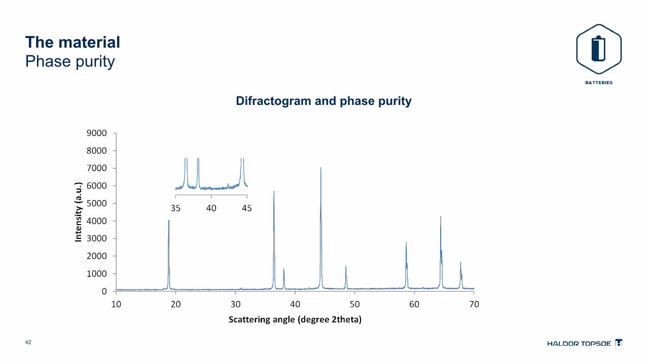
The material Phase purity
Difractogram and phase purity

43
The material Uniform and spherical secondary particles
Tap density: 2.3 g/cm3
BET surface area: 0.3 m2/g
20 µm
20 µm 20 µm
Tunable size distribution • 6 µm < D50 < 25 µm • Narrow or broad
10 µm

44
Li1.0Ni0.5Mn1.5O4 High voltage
10C
5C 2C 0.5C 1C 1C
0.5C charge and 0.5C discharge

45
Li1.0Ni0.5Mn1.5O4 High voltage
Fade rate: 0.09% per cycle at 55 °C
g kg t kt
0.5C charge and 0.5C discharge

46
Next generation - Still room for improvement
• Electrolyte degradation • Coulombic efficiency below 100% - electrochemical • Chemical reactivity in charged state
• Corrosion of the material • Ni and Mn found on anode • Ni:Mn ratio the same as in material

47
Strategies for increasing stability/lowering reactivity of Battery Materials
• Doping • Al in NCA (LiNi0.8Co0.15Al0.05O2), Li and Al in LMO (LiMn2O4), etc
• Relative large amounts needed • There can be drawbacks, e.g. lower capacity ……
• Electorlyte engineering • Increase stability by change of solvent • Additives that form protective layers
• Surface coating • AlF3, Li3PO4, ZrO2 .... etc
48
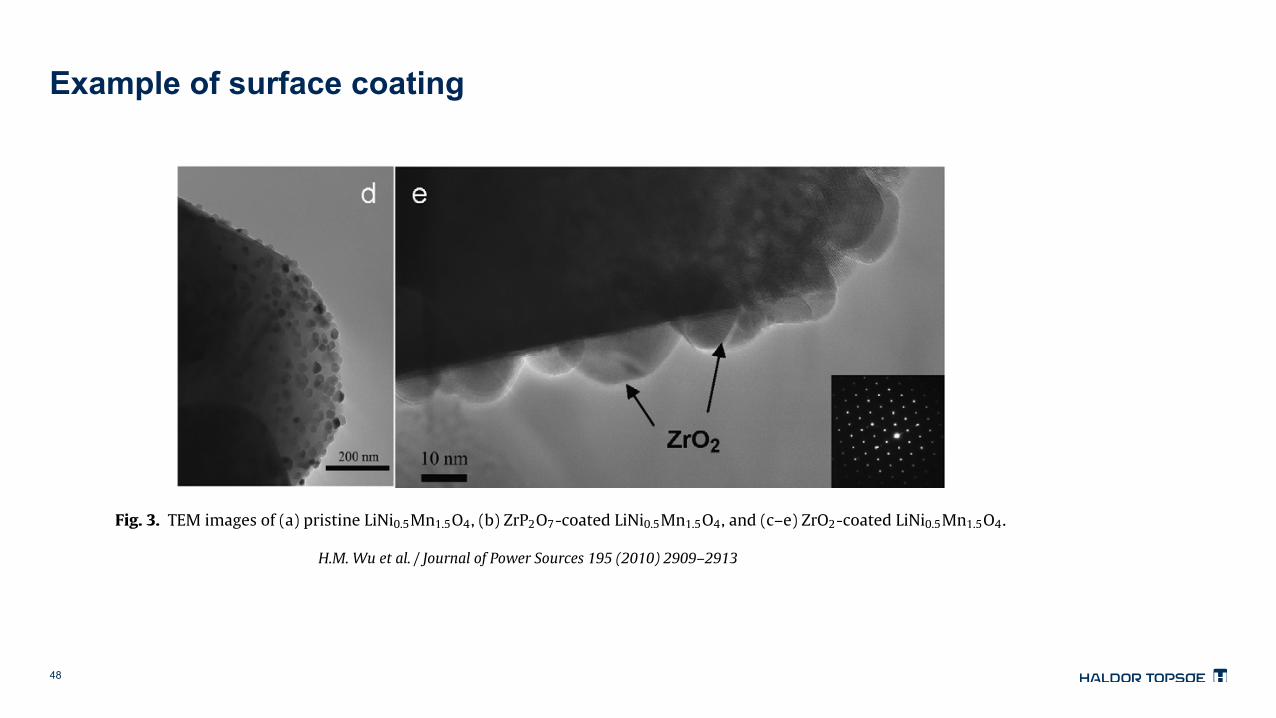
Example of surface coating
H.M. Wu et al. / Journal of Power Sources 195 (2010) 2909–2913 2911
Fig. 3. TEM images of (a) pristine LiNi0.5Mn1.5O4, (b) ZrP2O7-coated LiNi0.5Mn1.5O4, and (c–e) ZrO2-coated LiNi0.5Mn1.5O4.
LiNi0.5Mn1.5O4 electrodes were 120 and 118 mAh g−1, respectively.Because the coating amount in both cases is very small, the effecton the initial cell capacity was negligible when compared to that ofthe non-coated material (123 mAh g−1).
Fig. 5 shows the cycling performance of cells based on lithiummetal as the anode and pristine, ZrP2O7-coated, and ZrO2-coatedLiNi0.5Mn1.5O4 as the cathode. Cell cycling was carried out at 25 ◦Cfor 50 cycles and 55 ◦C for 150 cycles. At 25 ◦C, both coated and non-coated samples exhibited excellent cycle stability with no capacity
Fig. 4. First charge and discharge curves of (a) pristine LiNi0.5Mn1.5O4, (b)ZrP2O7-coated LiNi0.5Mn1.5O4, and (c) ZrO2-coated LiNi0.5Mn1.5O4. Note thatLNMO = LiNi0.5Mn1.5O4.
fade after 50 cycles. However, at 55 ◦C, the cells with the non-coatedand the ZrP2O7-coated cathodes exhibited 27% and 20% capacityfade after 150 cycles, respectively. In the non-coated cathode cell,the poor cycling performance was caused by the high surface reac-tivity of the Ni4+ from the charged cathode with the electrolyte.This reaction was accelerated with the increase in the cycling tem-perature. As shown in Fig. 3b, the ZrP2O7-modified material showsscattered and aggregated particles at the surface of the high-voltagecathode, resulting in limited protection against surface reactivity,especially during high-temperature cycling. The ZrO2-coated mate-rial, on the other hand, shows outstanding cyclability with lessthan 4% capacity fade after 150 cycles. This result is due to thegood surface protection from the uniform and highly dense ZrO2particles at the cathode surface (Fig. 3e), which play a role in sup-pressing the surface reactivity between the charged electrode andthe electrolyte.
To better understand the superior cycling stability at 55 ◦Cof the ZrO2-coated LiNi0.5Mn1.5O4 compared to the non-coatedor ZrP2O7-coated LiNi0.5Mn1.5O4, we performed AC impendencestudies of the cells after 5 and 100 cycles. The cells were cycledat 55 ◦C and rested for 1 h at room temperature before the ACimpedance measurements. Fig. 6 shows the EIS plots obtainedfor pristine, ZrP2O7-coated, and ZrO2-coated LiNi0.5Mn1.5O4. TheseNyquist plots were fitted using the equivalent circuit shown inFig. 6c and the fitting parameters are reported in Table 1. Accord-ing to the literature [25], Re represents the solution resistance; Rsfand CPE1 signify the diffusion resistance of Li+ ions through thesolid-electrolyte interface (SEI) layer and the corresponding con-stant phase element (CPE); Rct and CPE2 correspond to the chargetransfer resistance and the corresponding CPE, while Rw (not cal-

49
Inspiration from catalysis
• Only passivate the most active sites on the surface of the Battery Material to prevent reactions and corrosion
Ni4+

50
Take-home messages
• By proper process integration high temperature electrolysis can be very exergy efficient in transforming electrical energy into chemical energy
• Commercial batteries will in the next 10 years be dominated by insertion materials, a huge growth is foreseen due to automotive
• There can be shortage of Co, that can drive change of preferred battery materials • Li ion: high voltage spinel • Na ion: layered structure
• It is a trade off between different performance parameters to design optimal battery materials and batteries