snowplow installation instructions - western...
TRANSCRIPT
SnowplowInstallation Instructions
WESTERN PRODUCTS, P.O. BOX 245038, MILWAUKEE, WI 53224-9538
Lit. No. 62639October 5, 2001
CAUTIONSee your WESTERN® outlet for applicationrecommendations. The Selection List hasspecific vehicle and snowplow requirements.
CAUTIONRead this document before installing thesnowplow.
A DIVISION OF DOUGLAS DYNAMICS, L.L.C.
This document supersedes all editions with an earlier date.


TABLE OF CONTENTS
SAFETY
General Safety . . . . . . . . . . . . . . . . . . . . . . . . . . . 1
Battery Safety . . . . . . . . . . . . . . . . . . . . . . . . . . . 1
Torque Chart . . . . . . . . . . . . . . . . . . . . . . . . . . . . 1
MOUNT INSTALLATION
A-Frame . . . . . . . . . . . . . . . . . . . . . . . . . . . . . . . 2
Rubber Flap . . . . . . . . . . . . . . . . . . . . . . . . . . . . . 3
Stand . . . . . . . . . . . . . . . . . . . . . . . . . . . . . . . . . . 3
Lift Frame . . . . . . . . . . . . . . . . . . . . . . . . . . . . . . 4
Center Deflector . . . . . . . . . . . . . . . . . . . . . . . . . . 4
Rubber Deflector . . . . . . . . . . . . . . . . . . . . . . . . . 4
Blade Guide Assembly . . . . . . . . . . . . . . . . . . . . 6
Lift Channel, Hydraulic Unit,Hydraulic Fittings & Hoses Assembly . . . . . . . . 6
Light Bracket/Headlamps Assembly . . . . . . . . . 10
Hydraulic Unit Wiring Assembly . . . . . . . . . . . . . 10
Battery Cable Assembly . . . . . . . . . . . . . . . . . . 12
Vehicle Harness and Cable Installation . . . . . . . 13
Mounting the CabCommandHand-Held Control . . . . . . . . . . . . . . . . . . . . . . 16
Headlamp Harness Installation . . . . . . . . . . . . . . 16
Lit. No. 62639 October 5, 2001
OPERATIONAL TEST AND ADJUSTMENTS
Filling the Hydraulic Unit . . . . . . . . . . . . . . . . . . 17
Blade Drop Speed Adjustment . . . . . . . . . . . . . . 18
Final Inspection . . . . . . . . . . . . . . . . . . . . . . . . . 18
Coupling Lug Height Check . . . . . . . . . . . . . . . . 18
Vehicle Lighting Check . . . . . . . . . . . . . . . . . . . 19

1Lit. No. 62639 October 5, 2001
NOTE: Identifies tips, helpful hints andmaintenance information the owner/operatorshould know.
SAFETY
CAUTIONRefer to the current selection list for minimumvehicle recommendations and ballastrequirements.
GENERAL SAFETYRead these installation instructions and the labels onthe snowplow before installing or operating thesnowplow.
WARNING
Indicates a potentially hazardous situation that,if not avoided, could result in death or seriouspersonal injury.
CAUTION
Read instructions before assembling. Boltsshould be finger tight until instructed to tightenaccording to the torque chart. Use standardmethods and practices when attachingsnowplow including wearing safety glassesduring cutting, drilling and welding.
Recommended Fastener Torque Chart (Ft.-Lb.)
Size SAEGrade 2
SAEGrade 5
SAEGrade 8
1/4-205/16-183/8-163/8-247/16-141/2-139/16-125/8-113/4-107/8-91-8
611192430456693150202300
91831465075110150250378583
1328466875115165225370591893
Metric Grade 8.8 (Ft.-Lb.)Size TorqueSizeTorque
M 6M 8M 10
M 12M 14M 16
71735
6095155
These torque values apply to mount assembly fastenersexcept those noted in the instruction.
BATTERY SAFETY
CAUTION
Batteries normally produce explosive gases,which can cause personal injury. Therefore, donot allow flames, sparks or lit tobacco to comenear the battery. When charging or workingnear a battery, always cover your face andprotect your eyes, and also provide ventilation.
Batteries contain sulfuric acid that burns skin,eyes and clothing.
Disconnect the battery before removing orreplacing any electrical components.
TORQUE CHART
CAUTIONIndicates a situation that, if not avoided, couldresult in damage to product or property.
2Lit. No. 62639 October 5, 2001
A-FRAME
1. Lay both wings face down (on cardboard) next toeach other.
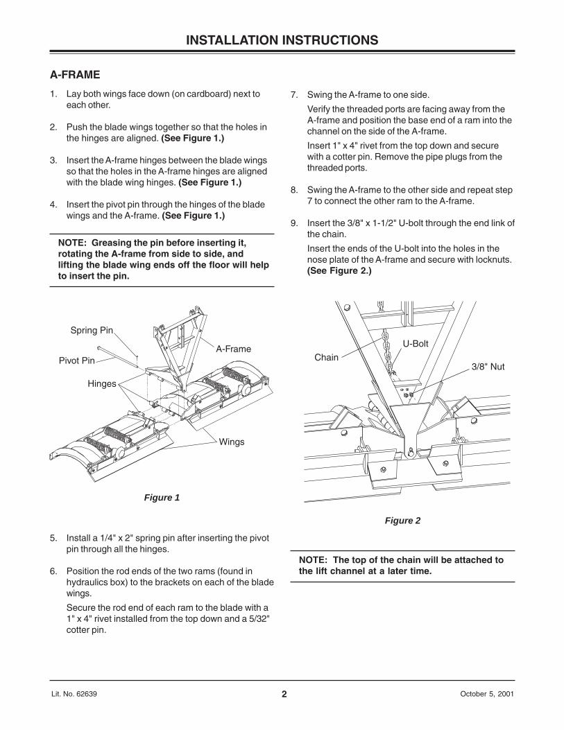
2. Push the blade wings together so that the holes inthe hinges are aligned. (See Figure 1.)
3. Insert the A-frame hinges between the blade wingsso that the holes in the A-frame hinges are alignedwith the blade wing hinges. (See Figure 1.)
4. Insert the pivot pin through the hinges of the bladewings and the A-frame. (See Figure 1.)
NOTE: Greasing the pin before inserting it,rotating the A-frame from side to side, andlifting the blade wing ends off the floor will helpto insert the pin.
INSTALLATION INSTRUCTIONS
5. Install a 1/4" x 2" spring pin after inserting the pivotpin through all the hinges.
6. Position the rod ends of the two rams (found inhydraulics box) to the brackets on each of the bladewings.
Secure the rod end of each ram to the blade with a1" x 4" rivet installed from the top down and a 5/32"cotter pin.
7. Swing the A-frame to one side.
Verify the threaded ports are facing away from theA-frame and position the base end of a ram into thechannel on the side of the A-frame.
Insert 1" x 4" rivet from the top down and securewith a cotter pin. Remove the pipe plugs from thethreaded ports.
8. Swing the A-frame to the other side and repeat step7 to connect the other ram to the A-frame.
9. Insert the 3/8" x 1-1/2" U-bolt through the end link ofthe chain.
Insert the ends of the U-bolt into the holes in thenose plate of the A-frame and secure with locknuts.(See Figure 2.)
Figure 2
Chain
U-Bolt
3/8" Nut
Spring Pin
Pivot Pin
Hinges
Wings
A-Frame
Figure 1
NOTE: The top of the chain will be attached tothe lift channel at a later time.
3Lit. No. 62639 October 5, 2001
INSTALLATION INSTRUCTIONS
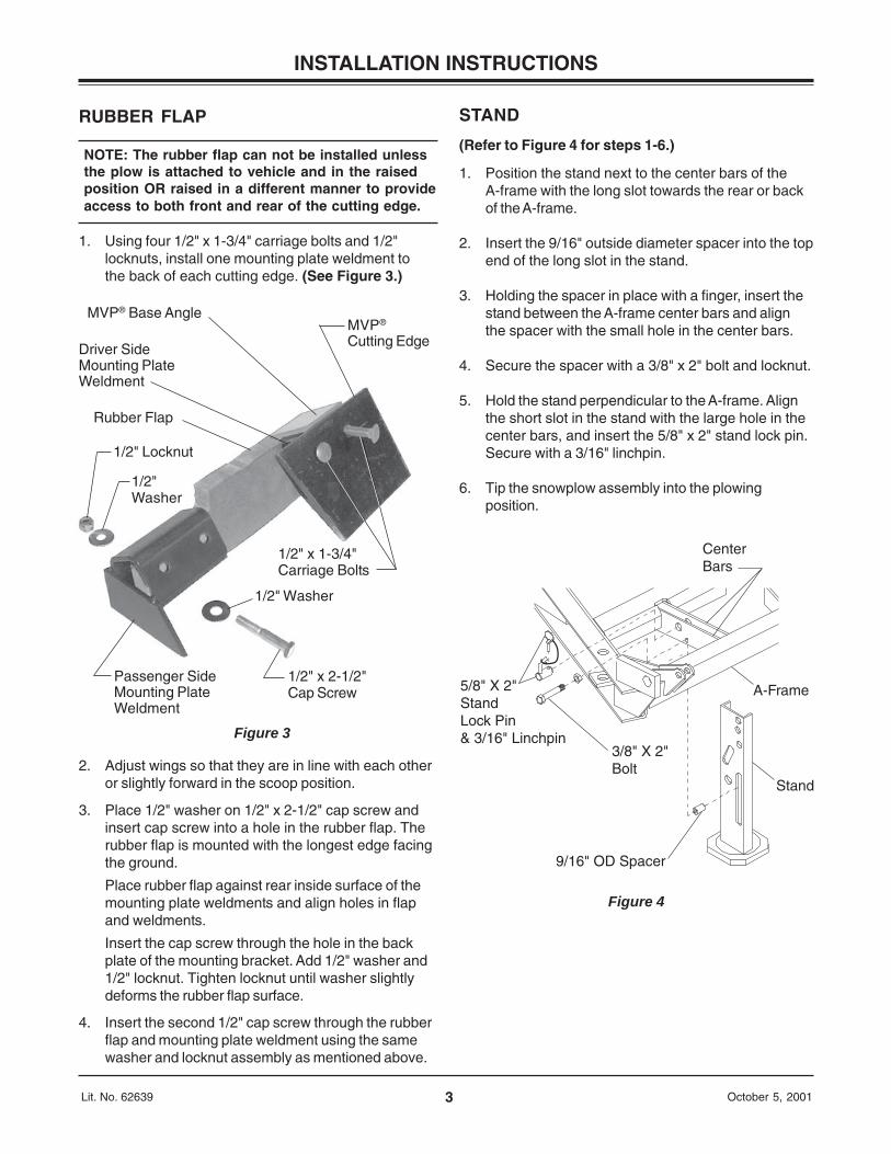
5/8" X 2"StandLock Pin& 3/16" Linchpin
3/8" X 2" Bolt
9/16" OD Spacer
A-Frame
CenterBars
Stand
Figure 4
Passenger SideMounting PlateWeldment
Figure 3
MVP®
Cutting Edge
MVP® Base Angle
Rubber Flap
Driver SideMounting PlateWeldment
1/2" x 1-3/4"Carriage Bolts
1/2" Locknut
1/2"Washer
1/2" x 2-1/2"Cap Screw
1/2" Washer
RUBBER FLAP
NOTE: The rubber flap can not be installed unlessthe plow is attached to vehicle and in the raisedposition OR raised in a different manner to provideaccess to both front and rear of the cutting edge.
1. Using four 1/2" x 1-3/4" carriage bolts and 1/2"locknuts, install one mounting plate weldment tothe back of each cutting edge. (See Figure 3.)
2. Adjust wings so that they are in line with each otheror slightly forward in the scoop position.
3. Place 1/2" washer on 1/2" x 2-1/2" cap screw andinsert cap screw into a hole in the rubber flap. Therubber flap is mounted with the longest edge facingthe ground.
Place rubber flap against rear inside surface of themounting plate weldments and align holes in flapand weldments.
Insert the cap screw through the hole in the backplate of the mounting bracket. Add 1/2" washer and1/2" locknut. Tighten locknut until washer slightlydeforms the rubber flap surface.
4. Insert the second 1/2" cap screw through the rubberflap and mounting plate weldment using the samewasher and locknut assembly as mentioned above.
STAND
(Refer to Figure 4 for steps 1-6.)
1. Position the stand next to the center bars of theA-frame with the long slot towards the rear or backof the A-frame.
2. Insert the 9/16" outside diameter spacer into the topend of the long slot in the stand.
3. Holding the spacer in place with a finger, insert thestand between the A-frame center bars and alignthe spacer with the small hole in the center bars.
4. Secure the spacer with a 3/8" x 2" bolt and locknut.
5. Hold the stand perpendicular to the A-frame. Alignthe short slot in the stand with the large hole in thecenter bars, and insert the 5/8" x 2" stand lock pin.Secure with a 3/16" linchpin.
6. Tip the snowplow assembly into the plowingposition.
4Lit. No. 62639 October 5, 2001
INSTALLATION INSTRUCTIONS
CenterDeflector
Top of Pivot Pin
A-frame
Figure 6
Edges are aligned
Figure 7
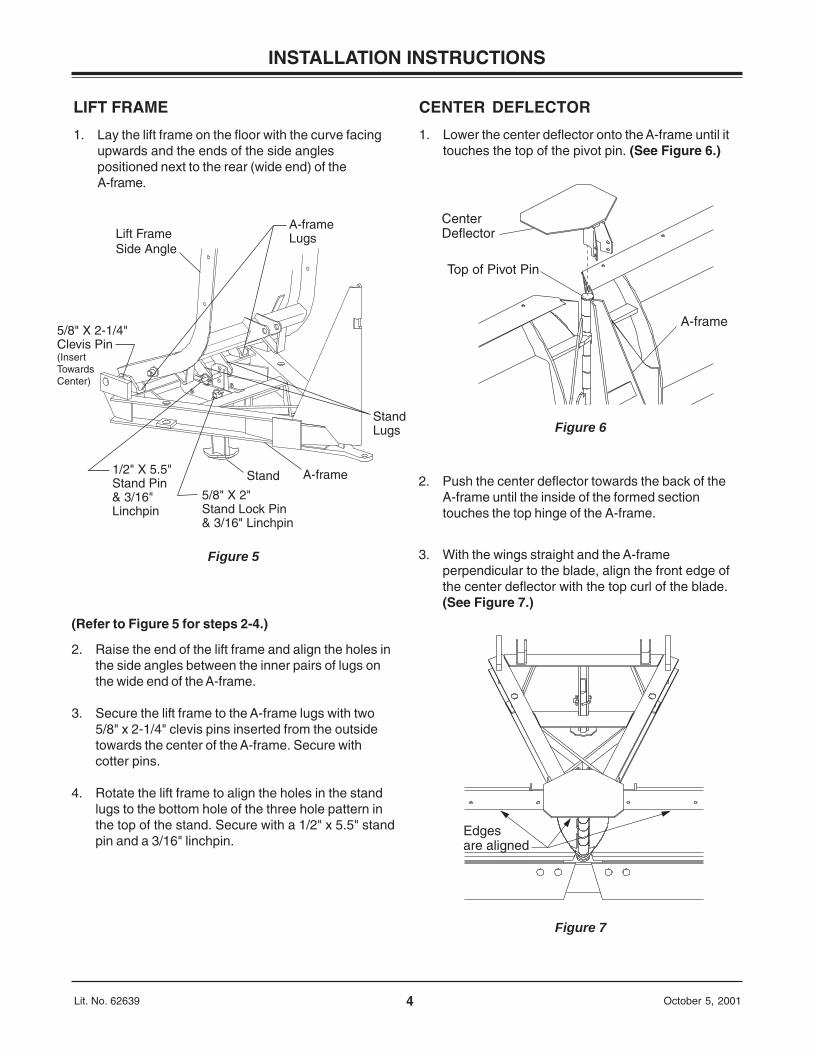
5/8" X 2-1/4"Clevis Pin (Insert Towards Center)
Lift FrameSide Angle
1/2" X 5.5" Stand Pin& 3/16" Linchpin
5/8" X 2" Stand Lock Pin & 3/16" Linchpin
Stand A-frame
StandLugs
A-frameLugs
Figure 5
LIFT FRAME
1. Lay the lift frame on the floor with the curve facingupwards and the ends of the side anglespositioned next to the rear (wide end) of theA-frame.
(Refer to Figure 5 for steps 2-4.)
2. Raise the end of the lift frame and align the holes inthe side angles between the inner pairs of lugs onthe wide end of the A-frame.
3. Secure the lift frame to the A-frame lugs with two5/8" x 2-1/4" clevis pins inserted from the outsidetowards the center of the A-frame. Secure withcotter pins.
4. Rotate the lift frame to align the holes in the standlugs to the bottom hole of the three hole pattern inthe top of the stand. Secure with a 1/2" x 5.5" standpin and a 3/16" linchpin.
CENTER DEFLECTOR
1. Lower the center deflector onto the A-frame until ittouches the top of the pivot pin. (See Figure 6.)
2. Push the center deflector towards the back of theA-frame until the inside of the formed sectiontouches the top hinge of the A-frame.
3. With the wings straight and the A-frameperpendicular to the blade, align the front edge ofthe center deflector with the top curl of the blade.(See Figure 7.)
5Lit. No. 62639 October 5, 2001
INSTALLATION INSTRUCTIONS
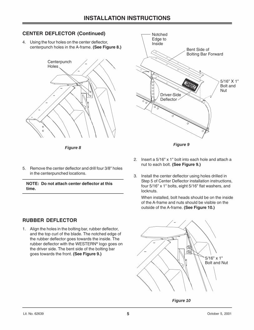
Centerpunch Holes
Figure 8
NotchedEdge to Inside
Bent Side ofBolting Bar Forward
5/16" X 1"Bolt andNut
Driver-SideDeflector
Figure 9
5/16" x 1" Bolt and Nut
Figure 10
CENTER DEFLECTOR (Continued)
4. Using the four holes on the center deflector,centerpunch holes in the A-frame. (See Figure 8.)
5. Remove the center deflector and drill four 3/8" holesin the centerpunched locations.
NOTE: Do not attach center deflector at thistime.
RUBBER DEFLECTOR
1. Align the holes in the bolting bar, rubber deflector,and the top curl of the blade. The notched edge ofthe rubber deflector goes towards the inside. Therubber deflector with the WESTERN® logo goes onthe driver side. The bent side of the bolting bargoes towards the front. (See Figure 9.)
2. Insert a 5/16" x 1" bolt into each hole and attach anut to each bolt. (See Figure 9.)
3. Install the center deflector using holes drilled inStep 5 of Center Deflector installation instructions,four 5/16" x 1" bolts, eight 5/16" flat washers, andlocknuts.
When installed, bolt heads should be on the insideof the A-frame and nuts should be visible on theoutside of the A-frame. (See Figure 10.)
6Lit. No. 62639 October 5, 2001
INSTALLATION INSTRUCTIONS
CAUTIONDO NOT OVERTIGHTEN. The lift channel mustpivot freely.
CAUTIONDo not use thread sealant/tape when connectinghoses to swivel fittings. This could damageproduct or property.
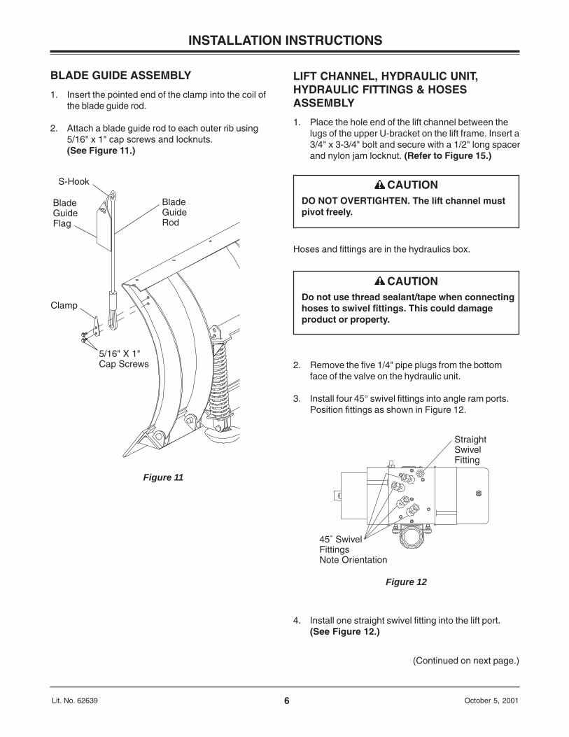
S-Hook
BladeGuideFlag
Clamp
5/16" X 1"Cap Screws
BladeGuideRod
Figure 11
45˚ SwivelFittingsNote Orientation
StraightSwivelFitting
Figure 12
BLADE GUIDE ASSEMBLY
1. Insert the pointed end of the clamp into the coil ofthe blade guide rod.
2. Attach a blade guide rod to each outer rib using5/16" x 1" cap screws and locknuts.(See Figure 11.)
LIFT CHANNEL, HYDRAULIC UNIT,HYDRAULIC FITTINGS & HOSESASSEMBLY
1. Place the hole end of the lift channel between thelugs of the upper U-bracket on the lift frame. Insert a3/4" x 3-3/4" bolt and secure with a 1/2" long spacerand nylon jam locknut. (Refer to Figure 15.)
4. Install one straight swivel fitting into the lift port.(See Figure 12.)
(Continued on next page.)
Hoses and fittings are in the hydraulics box.
2. Remove the five 1/4" pipe plugs from the bottomface of the valve on the hydraulic unit.
3. Install four 45° swivel fittings into angle ram ports.Position fittings as shown in Figure 12.
7Lit. No. 62639 October 5, 2001
INSTALLATION INSTRUCTIONS
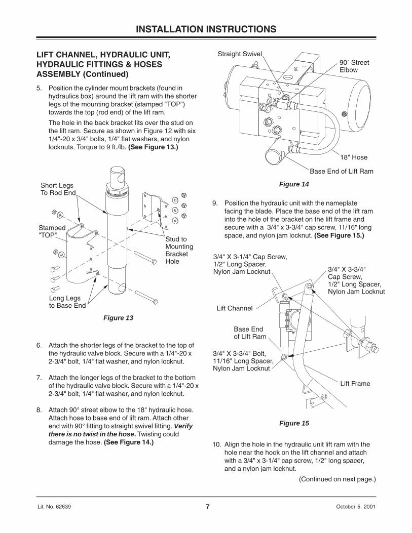
Straight Swivel90˚ StreetElbow
18" Hose
Base End of Lift Ram
Figure 14
3/4" X 3-1/4" Cap Screw,1/2" Long Spacer,Nylon Jam Locknut
Lift Channel
Base End of Lift Ram
3/4" X 3-3/4" Bolt,11/16" Long Spacer,Nylon Jam Locknut
3/4" X 3-3/4" Cap Screw,1/2" Long Spacer,Nylon Jam Locknut
Lift Frame
Figure 15
Short LegsTo Rod End
Stamped"TOP"
Long Legsto Base End
Stud toMountingBracket Hole
Figure 13
LIFT CHANNEL, HYDRAULIC UNIT,HYDRAULIC FITTINGS & HOSESASSEMBLY (Continued)
5. Position the cylinder mount brackets (found inhydraulics box) around the lift ram with the shorterlegs of the mounting bracket (stamped “TOP”)towards the top (rod end) of the lift ram.
The hole in the back bracket fits over the stud onthe lift ram. Secure as shown in Figure 12 with six1/4"-20 x 3/4" bolts, 1/4" flat washers, and nylonlocknuts. Torque to 9 ft./lb. (See Figure 13.)
6. Attach the shorter legs of the bracket to the top ofthe hydraulic valve block. Secure with a 1/4"-20 x2-3/4" bolt, 1/4" flat washer, and nylon locknut.
7. Attach the longer legs of the bracket to the bottomof the hydraulic valve block. Secure with a 1/4"-20 x2-3/4" bolt, 1/4" flat washer, and nylon locknut.
8. Attach 90° street elbow to the 18" hydraulic hose.Attach hose to base end of lift ram. Attach otherend with 90° fitting to straight swivel fitting. Verifythere is no twist in the hose. Twisting coulddamage the hose. (See Figure 14.)
9. Position the hydraulic unit with the nameplatefacing the blade. Place the base end of the lift raminto the hole of the bracket on the lift frame andsecure with a 3/4" x 3-3/4" cap screw, 11/16" longspace, and nylon jam locknut. (See Figure 15.)
10. Align the hole in the hydraulic unit lift ram with thehole near the hook on the lift channel and attachwith a 3/4" x 3-1/4" cap screw, 1/2" long spacer,and a nylon jam locknut.
(Continued on next page.)
8Lit. No. 62639 October 5, 2001
INSTALLATION INSTRUCTIONS
90˚ StreetElbow Fittings
Rod End Fitting45˚ Towards Rear
Base EndFitting Straight Up
38" Hose
Figure 16
Driver-Side Rod End Hose
Passenger-SideRod End Hose
Figure 17
(Continued on next page.)
Passenger-SideRod Hose
Driver-SideRod End Hose
Figure 18
LIFT CHANNEL, HYDRAULIC UNIT,HYDRAULIC FITTINGS & HOSESASSEMBLY (Continued)
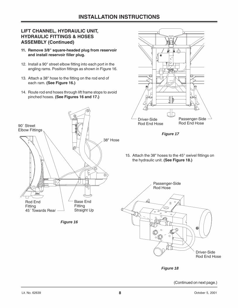
11. Remove 3/8" square-headed plug from reservoirand install reservoir filler plug.
12. Install a 90° street elbow fitting into each port in theangling rams. Position fittings as shown in Figure 16.
13. Attach a 38" hose to the fitting on the rod end ofeach ram. (See Figure 16.)
14. Route rod end hoses through lift frame stops to avoidpinched hoses. (See Figures 16 and 17.)
15. Attach the 38" hoses to the 45° swivel fittings onthe hydraulic unit. (See Figure 18.)
9Lit. No. 62639 October 5, 2001
INSTALLATION INSTRUCTIONS
Driver-SideBase End Hose
Passenger-SideBase End Hose
Figure 20
Passenger-SideBase End Hose
Driver-SideBase End Hose
Figure 21
36" Hose
Figure 19
LIFT CHANNEL, HYDRAULIC UNIT,HYDRAULIC FITTINGS & HOSESASSEMBLY (Continued)
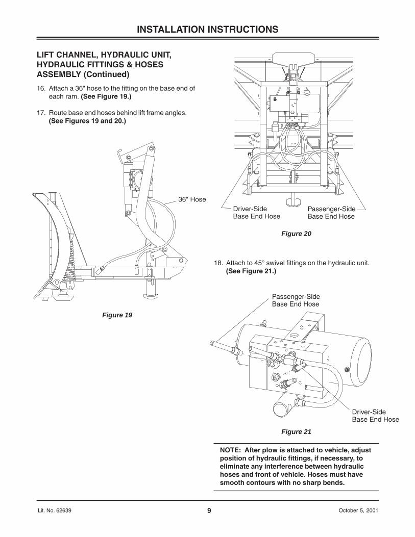
16. Attach a 36" hose to the fitting on the base end ofeach ram. (See Figure 19.)
17. Route base end hoses behind lift frame angles.(See Figures 19 and 20.)
18. Attach to 45° swivel fittings on the hydraulic unit.(See Figure 21.)
NOTE: After plow is attached to vehicle, adjustposition of hydraulic fittings, if necessary, toeliminate any interference between hydraulichoses and front of vehicle. Hoses must havesmooth contours with no sharp bends.
10Lit. No. 62639 October 5, 2001
INSTALLATION INSTRUCTIONS
Top Light Bracket
Bottom Light Bracket
Lift Frame Side Angle
3/8" X 1-1/4" Bolts & Locknuts
Figure 22
LIGHT BRACKETS/HEADLAMPSASSEMBLY
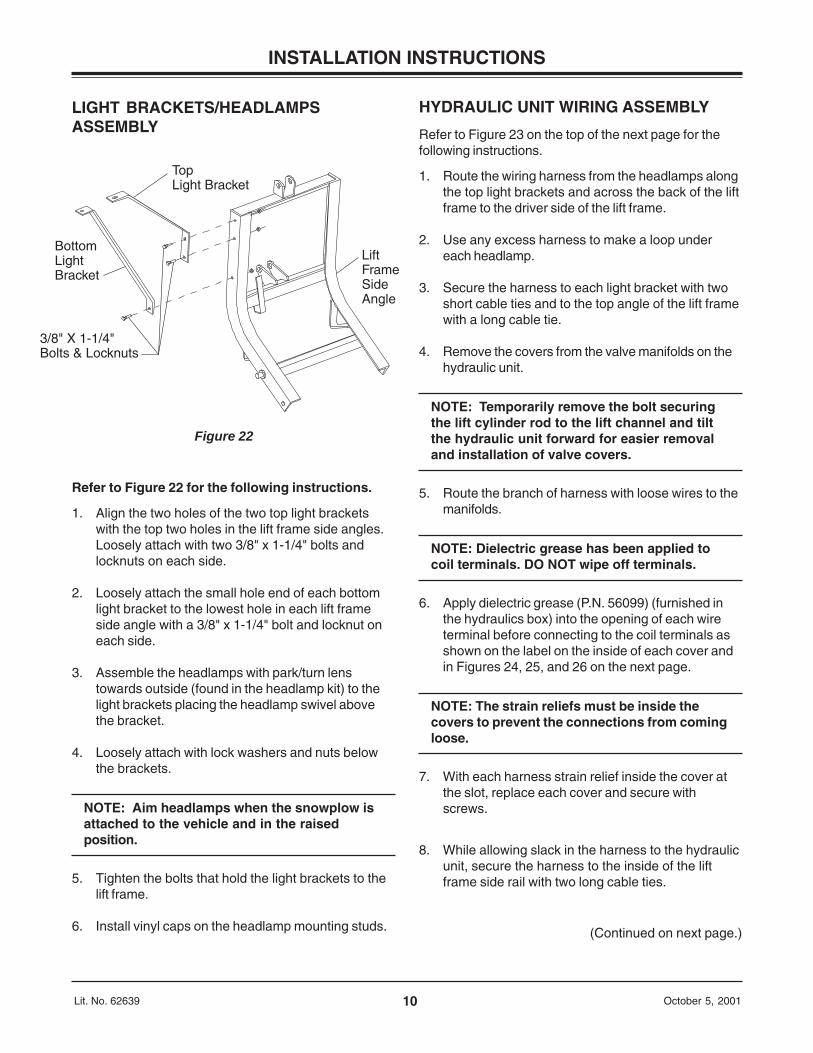
Refer to Figure 22 for the following instructions.
1. Align the two holes of the two top light bracketswith the top two holes in the lift frame side angles.Loosely attach with two 3/8" x 1-1/4" bolts andlocknuts on each side.
2. Loosely attach the small hole end of each bottomlight bracket to the lowest hole in each lift frameside angle with a 3/8" x 1-1/4" bolt and locknut oneach side.
3. Assemble the headlamps with park/turn lenstowards outside (found in the headlamp kit) to thelight brackets placing the headlamp swivel abovethe bracket.
4. Loosely attach with lock washers and nuts belowthe brackets.
NOTE: Aim headlamps when the snowplow isattached to the vehicle and in the raisedposition.
5. Tighten the bolts that hold the light brackets to thelift frame.
6. Install vinyl caps on the headlamp mounting studs.
HYDRAULIC UNIT WIRING ASSEMBLY
Refer to Figure 23 on the top of the next page for thefollowing instructions.
1. Route the wiring harness from the headlamps alongthe top light brackets and across the back of the liftframe to the driver side of the lift frame.
2. Use any excess harness to make a loop undereach headlamp.
3. Secure the harness to each light bracket with twoshort cable ties and to the top angle of the lift framewith a long cable tie.
4. Remove the covers from the valve manifolds on thehydraulic unit.
NOTE: Temporarily remove the bolt securingthe lift cylinder rod to the lift channel and tiltthe hydraulic unit forward for easier removaland installation of valve covers.
5. Route the branch of harness with loose wires to themanifolds.
NOTE: Dielectric grease has been applied tocoil terminals. DO NOT wipe off terminals.
6. Apply dielectric grease (P.N. 56099) (furnished inthe hydraulics box) into the opening of each wireterminal before connecting to the coil terminals asshown on the label on the inside of each cover andin Figures 24, 25, and 26 on the next page.
NOTE: The strain reliefs must be inside thecovers to prevent the connections from comingloose.
7. With each harness strain relief inside the cover atthe slot, replace each cover and secure withscrews.
8. While allowing slack in the harness to the hydraulicunit, secure the harness to the inside of the liftframe side rail with two long cable ties.
(Continued on next page.)
11Lit. No. 62639 October 5, 2001
INSTALLATION INSTRUCTIONS
HYDRAULIC UNIT WIRING ASSEMBLY (Continued)
Figure 24
Figure 25
Figure 26
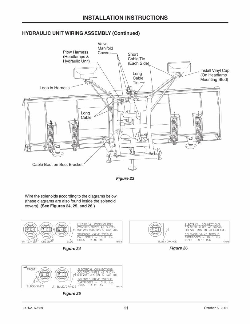
Plow Harness (Headlamps & Hydraulic Unit)
ValveManifoldCovers
Long Cable Tie
Short Cable Tie (Each Side)
Install Vinyl Cap(On HeadlampMounting Stud)
Loop in Harness
Cable Boot on Boot Bracket
Long Cable
Figure 23
Wire the solenoids according to the diagrams below(these diagrams are also found inside the solenoidcovers). (See Figures 24, 25, and 26.)
12Lit. No. 62639 October 5, 2001
INSTALLATION INSTRUCTIONS
Motor TerminalPOSITIVE
Motor TerminalNEGATIVE
LargeRed Wire
LargeBlack Wire
Small Red Wire–Female
Black/Orange Wire
Small Red Wire–Male
Figure 27
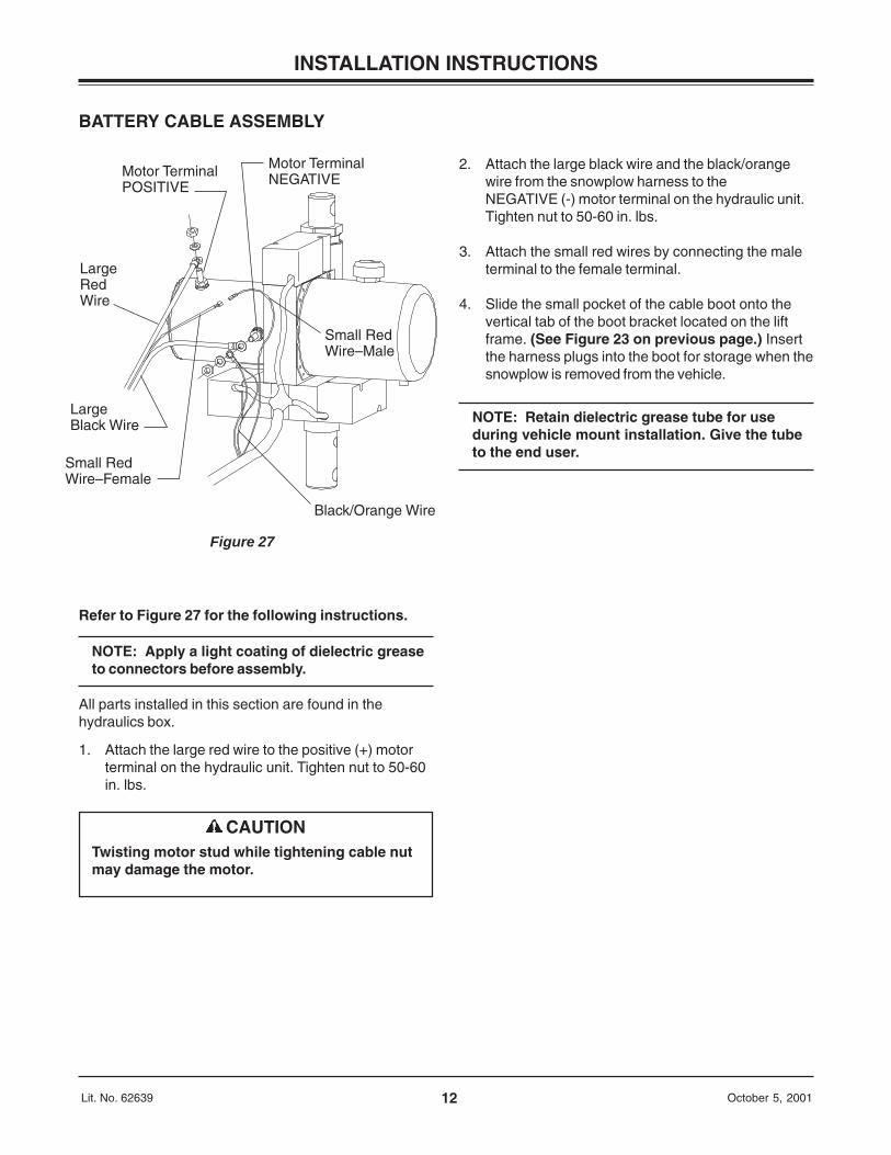
CAUTIONTwisting motor stud while tightening cable nutmay damage the motor.
BATTERY CABLE ASSEMBLY
Refer to Figure 27 for the following instructions.
NOTE: Apply a light coating of dielectric greaseto connectors before assembly.
All parts installed in this section are found in thehydraulics box.
1. Attach the large red wire to the positive (+) motorterminal on the hydraulic unit. Tighten nut to 50-60in. lbs.
2. Attach the large black wire and the black/orangewire from the snowplow harness to theNEGATIVE (-) motor terminal on the hydraulic unit.Tighten nut to 50-60 in. lbs.
3. Attach the small red wires by connecting the maleterminal to the female terminal.
4. Slide the small pocket of the cable boot onto thevertical tab of the boot bracket located on the liftframe. (See Figure 23 on previous page.) Insertthe harness plugs into the boot for storage when thesnowplow is removed from the vehicle.
NOTE: Retain dielectric grease tube for useduring vehicle mount installation. Give the tubeto the end user.

13Lit. No. 62639 October 5, 2001
INSTALLATION INSTRUCTIONS
VEHICLE HARNESS AND VEHICLE CABLE INSTALLATION
22" Red Battery Cable
Red Wires
Large Terminals
Relay - SolenoidHydraulic System (Motor Relay)
SmallTerminals
Brown/Green
Brown/Red
Orange/Black
Vehicle Harness
Vehicle Cable Assembly
Black Wire
To Negative Battery Terminal
Hand-Held Control
ON/OFF Switch
Control Bracket
Connector
Red Wire
Self-Stripping Connector (Blue)
Vehicle Wire Controlled byIgnition (Key) Switch. See Steps 24 and 25.
Wires to Headlamp Relays(See Plug-In Harness Instructions)
Vehicle Harness Connector
Vehicle Cable Connector
Fuse Holder
Red Wire
(Passed Through Grill or Bumper Openings)(Apply Dielectric Grease to Pin Cavities)
Park or Turn Harness
Figure 28
NOTE: Use dielectric grease to preventcorrosion on all connections. Fill receptaclesand lightly coat ring terminals and bladesbefore assembly.
(Continued on next page.)
NOTE: This is a “low side” drive electricalsystem for the hydraulic unit. With a “low side”drive system, positive is provided continuouslyto the solenoid coils, and the ground isswitched on and off to control the solenoids.
1. Identify the wires for the parking lamp on the driverside and for the turn signals on both sides. Attach ablack, self-stripping bullet receptacle connector(found in the headlamp kit) to each of these threewires.
2. Turn off the vehicle ignition and disconnect both theNEGATIVE (-) and POSITIVE (+) battery cables.
3. Find a location for the motor relay where it will beprotected from road splash and will be within 18" ofthe vehicle primary battery.
NOTE: Motor relay terminals must be vertical orhorizontal.
4. Using the motor relay mounting plate as a template,drill two 9/32" holes and mount the motor relay toholes using 1/4" X 3/4" bolts, washers, andlocknuts.
14Lit. No. 62639 October 5, 2001
INSTALLATION INSTRUCTIONS
CAUTIONBefore drilling any holes, check both sides ofthe material for any wires, fuel lines, fuel tanks,etc., that may be damaged by drilling.
VEHICLE HARNESS AND VEHICLECABLE INSTALLATION (Continued)
5. Route the 22" red battery cable between a largemotor relay terminal and the POSITIVE battery ter-minal avoiding sharp edges and hot or moving parts.
See vehicle harness and vehicle cableinstallation in mount box instruction for specialbattery connection information.
Park or turn harness kits (see Harness Kit selectionin mount box instructions for applications):
• Locate insulated end of park or turn harnessbehind driver side headlamp.
• Route red and black wires with ring terminals tothe battery.
• Route black wire to battery ground terminal.DO NOT attach ground at this time.
• Attach red wire with fuse holder to either batterypositive terminal or to motor relay terminal with22" red cable attached.
Secure 22" red cable on top of any other ringterminals to motor relay terminal with lock washerand 5/16"-24 jam nut.
Secure positive battery terminal using specialinstructions from mount box or original fasteners.
6. Stretch the rectangular openings of the plug coverstraps (found in the harness kit) over the connectorends of the vehicle cable assembly (found in thehydraulics box) and the 12-pin vehicle harness(found in the light kit). Place the plug covers overthe molds on the harnesses.
7. Find a location in the vehicle grill or bumper openingon the battery side for routing the vehicle cableconnector.
The best location is at least 10-1/2" from the centerof the grill and at a convenient height for connectingthe snowplow plugs. Allow the connectors of theharness and cable to hang out in front of the grill orbumper opening. Allow enough slack so it is easyto connect and disconnect the connectors.
8. Route the vehicle cable through the grill or bumperopening at the selected location and through oraround the radiator bulkhead to the motor relayavoiding sharp edges, and hot or moving parts.
9. Attach the large red wire from the vehicle cable tothe unused large motor relay terminal with a lockwasher and 5/16"-24 jam nut.
10. Route the black wire from the vehicle cable to theexisting terminal fastener on the NEGATIVE batteryterminal. DO NOT attach wire at this time.
11. Find a location in the vehicle grill or bumper openingon the driver side for routing the vehicle harness.See Figure 28 on the previous page for routing thevehicle harness.
12. Route the vehicle harness through grill or bumperopening and around, or through radiator bulkhead.
13. Route the wires that break out of the vehicleharness to the area behind the driver-sideheadlamp. Route the rest of harness to the firewall.
14. Drill a 5/8" hole through the firewall of the truck in aconvenient location away from sharp edges and hotor moving parts.
15. Route the harness breakout with the orangew/black stripe, brown w/red stripe, brown w/greenstripe, and red wires to the motor relay.
16. Install the brown w/red stripe and brown w/greenstripe wires to the small terminals of the motor relay.Secure with #10 lock washers and 10-32 nuts.
17. Connect the black wire of the vehicle cable, thevehicle harness orange w/black stripe ring terminaland any park or turn harness black wire ringterminal(s) to the NEGATIVE battery terminal.
18. All vehicles with DRL’s - Insert fuse holder on pinkwire of DRL Adapter Kit (P.N. 61584) through firewallfirst. Route end of pink wire with receptacles to areaof driver-side headlamp.
19. Remove the packing material from the end of theharness near the fuse. This will expose 10 socket-type terminals. Push the fuse holder through thefirewall hole and then carefully feed the end of theharness with the 10 terminals through to the cab.
(Continued on next page.)
15Lit. No. 62639 October 5, 2001
INSTALLATION INSTRUCTIONS
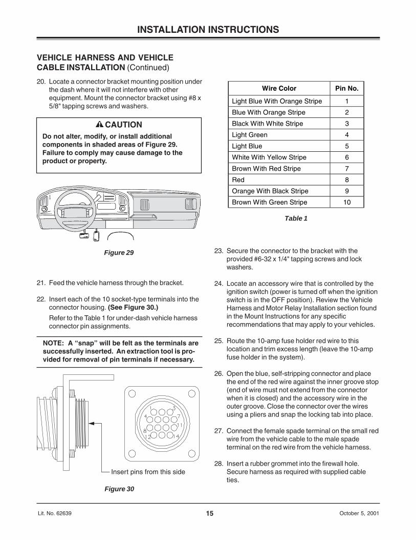
Wire Color Pin No.
Light Blue With Orange Stripe 1
Blue With Orange Stripe 2
Black With White Stripe 3
Light Green 4
Light Blue 5
White With Yellow Stripe 6
Brown With Red Stripe 7
Red 8
Orange With Black Stripe 9
Brown With Green Stripe 10
Table 1
Insert pins from this side
Figure 30
CAUTIONDo not alter, modify, or install additionalcomponents in shaded areas of Figure 29.Failure to comply may cause damage to theproduct or property.
VEHICLE HARNESS AND VEHICLECABLE INSTALLATION (Continued)
20. Locate a connector bracket mounting position underthe dash where it will not interfere with otherequipment. Mount the connector bracket using #8 x5/8" tapping screws and washers.
Figure 29
21. Feed the vehicle harness through the bracket.
22. Insert each of the 10 socket-type terminals into theconnector housing. (See Figure 30.)
Refer to the Table 1 for under-dash vehicle harnessconnector pin assignments.
NOTE: A “snap” will be felt as the terminals aresuccessfully inserted. An extraction tool is pro-vided for removal of pin terminals if necessary.
23. Secure the connector to the bracket with theprovided #6-32 x 1/4" tapping screws and lockwashers.
24. Locate an accessory wire that is controlled by theignition switch (power is turned off when the ignitionswitch is in the OFF position). Review the VehicleHarness and Motor Relay Installation section foundin the Mount Instructions for any specificrecommendations that may apply to your vehicles.
25. Route the 10-amp fuse holder red wire to thislocation and trim excess length (leave the 10-ampfuse holder in the system).
26. Open the blue, self-stripping connector and placethe end of the red wire against the inner groove stop(end of wire must not extend from the connectorwhen it is closed) and the accessory wire in theouter groove. Close the connector over the wiresusing a pliers and snap the locking tab into place.
27. Connect the female spade terminal on the small redwire from the vehicle cable to the male spadeterminal on the red wire from the vehicle harness.
28. Insert a rubber grommet into the firewall hole.Secure harness as required with supplied cableties.
16Lit. No. 62639 October 5, 2001
HEADLAMP HARNESS INSTALLATION
Specific instructions for the installationof the Plug-In Harness to the vehicle
headlights and the headlamp switchingrelays will be found either in:
special instructions contained inthe harness kit specified in the
Selection List
or
in the installation instructionsfound in the mount box.
INSTALLATION INSTRUCTIONS
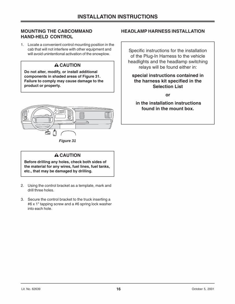
CAUTIONDo not alter, modify, or install additionalcomponents in shaded areas of Figure 31.Failure to comply may cause damage to theproduct or property.
Figure 31
CAUTIONBefore drilling any holes, check both sides ofthe material for any wires, fuel lines, fuel tanks,etc., that may be damaged by drilling.
MOUNTING THE CABCOMMANDHAND-HELD CONTROL
1. Locate a convenient control mounting position in thecab that will not interfere with other equipment andwill avoid unintentional activation of the snowplow.
2. Using the control bracket as a template, mark anddrill three holes.
3. Secure the control bracket to the truck inserting a#6 x 1" tapping screw and a #6 spring lock washerinto each hole.
17Lit. No. 62639 October 5, 2001
OPERATIONAL TEST AND ADJUSTMENTS
DEXRON is a trademark of General Motors Corporation
FILLING THE HYDRAULIC UNIT
NOTE: Mount the plow assembly to the vehicle.(See label on back of blade or Owner’s Manualfor mounting instructions.)
Verify proper hydraulic hose routing see page 8 and 9.
NOTE: Add oil when all cylinders are retracted.
1. Fill the reservoir to the dipstick level while in theVee position with the snowplow lowered (lift ramretracted all the way).
2. Turn ignition (key) switch to the ON orACCESSORY position. Press the control powerbutton. The control indicator light will turn on.
3. Turn the control ON/OFF switch to the ON position.
4. Hold the MODE button down for 2 seconds (themode light will flash) to put the snowplow in singlewing mode. The right and left buttons now work astoggles. For example, pressing the button once willretract the blade wing. Pressing the button againwill extend the blade wing.
5. Extend and retract the driver-side wing severaltimes. Return all rams to the retracted position.Refill reservoir.
6. Screw dipstick in completely to read fill level. Fillwith fluid according to dipstick reading.
7. Extend and retract the passenger-side wing severaltimes. Return all rams to the retracted position.Refill reservoir.
8. Screw dipstick in completely to read fill level. Fillwith fluid according to dipstick reading.
9. Raise and lower the snowplow several times.Return to the lower position retracting the cylinderscompletely.
10. With angling cylinders and the lift cylinder retracted,refill the system through the fill hole. Use thedipstick to indicate the level. Fill to full.
SYSTEM CAPACITY
• Reservoir—1-3/4 quart
• Complete System—2-1/2 quarts
USE
• WESTERN® High Performance Fluidto -25° F (-32° C)Part No. 49311 - QuartPart No. 49330 - Gallon
• Automatic Transmission Fluid (ATF)DEXRON® III to -10° F (-23° C)
• Texaco 1537 Aircraft Hydraulic Oil fortemperatures below -25° F (-32° C)
18Lit. No. 62639 October 5, 2001
OPERATIONAL TEST AND ADJUSTMENTS
FINAL INSPECTION1. Make sure all fasteners and hydraulic and electrical
connections are tight.
2. Check ram packing nuts for oil leakage. Ifexcessive leakage is observed, tighten the packingnut 1/4 turn after you feel the nut contact thepacking.
NOTE: Do not over tighten packing nuts. Overtightening affects cylinder operation andshortens the life of the packing. A short periodof normal operation will allow chevron packingsto become saturated, and leakage will normallystop. A small amount of leakage is necessary toproperly lubricate the cylinder rod.
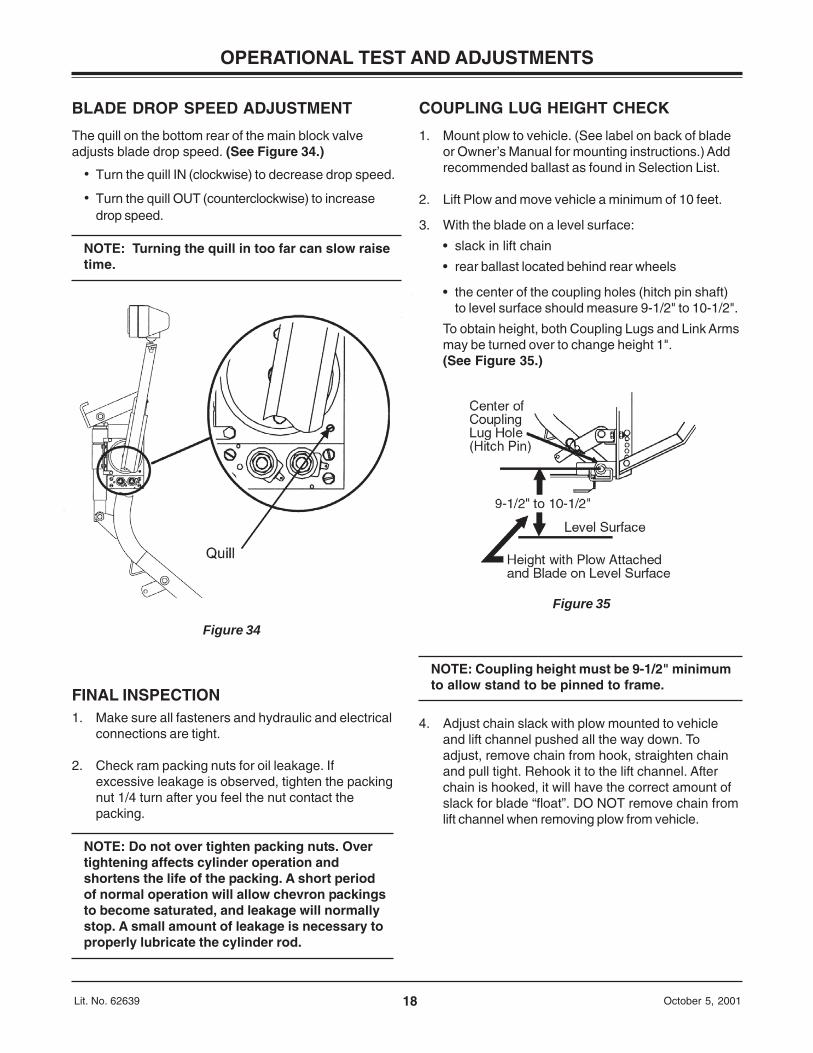
COUPLING LUG HEIGHT CHECK
1. Mount plow to vehicle. (See label on back of bladeor Owner’s Manual for mounting instructions.) Addrecommended ballast as found in Selection List.
2. Lift Plow and move vehicle a minimum of 10 feet.
3. With the blade on a level surface:
• slack in lift chain
• rear ballast located behind rear wheels
• the center of the coupling holes (hitch pin shaft)to level surface should measure 9-1/2" to 10-1/2".
To obtain height, both Coupling Lugs and Link Armsmay be turned over to change height 1".(See Figure 35.)
NOTE: Coupling height must be 9-1/2" minimumto allow stand to be pinned to frame.
4. Adjust chain slack with plow mounted to vehicleand lift channel pushed all the way down. Toadjust, remove chain from hook, straighten chainand pull tight. Rehook it to the lift channel. Afterchain is hooked, it will have the correct amount ofslack for blade “float”. DO NOT remove chain fromlift channel when removing plow from vehicle.
Figure 35
Figure 34
BLADE DROP SPEED ADJUSTMENT
The quill on the bottom rear of the main block valveadjusts blade drop speed. (See Figure 34.)
• Turn the quill IN (clockwise) to decrease drop speed.
• Turn the quill OUT (counterclockwise) to increasedrop speed.
NOTE: Turning the quill in too far can slow raisetime.
19Lit. No. 62639 October 5, 2001
OPERATIONAL TEST AND ADJUSTMENTS
VEHICLE LIGHTING CHECK
1. Check the operation of vehicle and plow lights withplow mounted to vehicle and all harnessesconnected.
Turn signals and parking lamps
Parking lamps ON• Both vehicle and plow parking lamps should be
on at the same time.
Right turn signal ON• Both vehicle and plow right turn signal lamps
should flash at the same time.
Left turn signal ON• Both vehicle and plow left turn signal lamps
should flash at the same time.
Headlamps
Move vehicle headlamp switch to the ON position.Connecting and disconnecting the 12-pin plow plugfrom the vehicle harness connector should switchbetween vehicle and plow headlamps as follows:
12-pin plow plug DISCONNECTED• Vehicle headlamps should be on.• Plow headlamps should be off.
12-pin plow plug CONNECTED• Plow headlamps should be on.• Vehicle headlamps should be off.
Dimmer switch should dim whichever headlamps areoperating. The high beam indicator on the dashshould light when either set of headlamps is on highbeam.
2. Connect plow plug to vehicle harness connector.Raise plow and aim plow headlamps according toSAE J599 Lighting Inspection Code (see ServiceBulletin SP 608) and any state or localregulations.
3. Check aim of vehicle headlamps with plow removed.
4. When plow is removed from the vehicle, install plugcovers on vehicle harness connectors and insert theplow plugs into the boot on the hydraulic unit.
After using the snowplow for 5-10 hours, retorqueall mount assembly fasteners.

Printed in U.S.A. October 5, 2001Lit. No. 62639
WESTERN PRODUCTSP.O. BOX 245038MILWAUKEE, WI 53224-9538
Western Products reserves the right under its Product Improvement Policy to change construction or design details and furnish equipmentwhen so altered without reference to illustrations or specifications used herein. Western Products and the vehicle manufacturer may requireand/or recommend optional equipment for snow removal. This product is manufactured under the following patents: 4,280,062; 5,420,480;and Re 35,700 with additional patents pending. Western Products offers a limited warranty on the snowplows and accessories. Seeseparately printed page for this important information. The following are registered® trademarks of Douglas Dynamics, L.L.C.: MVP®,UNIMOUNT®, and WESTERN®.
A DIVISION OF DOUGLAS DYNAMICS, L.L.C.