snmp alarm adaptor | setup guide · this setup guide details installation and the available...
TRANSCRIPT

SETUP GUIDESNMP ALARM ADAPTOR
COMPATIBLE WITHSIGMA, RADIAN, TPCMQ & BLUEstreak
POWER SHELVES
Document Number: SNMP-MAN Rev. 4
UNIPOWER, LLC65 Industrial Park RdDunlap, TN 37327Phone: +1-954-346-2442Toll Free: 1-800-440-3504Web site: www.unipowerco.com
© 2019 UNIPOWER LLCAll Rights Reserved
P O W E R I N G T E C H N O L O G Y

Page 2
SNMP ALARM MODULESETUP GUIDE
P O W E R I N G T E C H N O L O G Y
Document Number: SNMP-MAN Rev. 4 snmp_alarm_adaptor-man-rev4-0719.indd
REV DESCRIPTION CHK’d & APPR’d / DATE4 PCO# 45400 MM / 07-31-19
Product SupportProduct support can be obtained using the following addresses and telephone numbers.
Corporate office: UNIPOWER, LLC210 N University DrCoral Springs, FL 33071 United States
Manufacturing facility:UNIPOWER, LLC65 Industrial Park RdDunlap, TN 37327United States
Manufacturing facility:UNIPOWER Slovakia SRO ZLATOVSKA 1279 Business Center 2291105 Trencin, Slovakia
Phone: +1-954-346-2442Toll Free: 1-800-440-3504Web site – www.unipowerco.com
When contacting UNIPOWER, please be prepared to provide:
1. The product model number, spec number, S build number, and serial number - see the equipment nameplate on the front panel2. Your company’s name and address3. Your name and title4. The reason for the contact5. If there is a problem with product operation:
• Is the problem intermittent or continuous?• What revision is the firmware?• What actions were being performed prior to the appearance of the problem?• What actions have been taken since the problem occurred?
Page 3
SNMP ALARM MODULESETUP GUIDE
P O W E R I N G T E C H N O L O G Y
Document Number: SNMP-MAN Rev. 4 snmp_alarm_adaptor-man-rev4-0719.indd
FIGURES
Figure 1 SNMP Alarm Module ....................................................................................................4Figure 2 Rear View .......................................................................................................................6Figure 3 Initial Log On Page ........................................................................................................9Figure 4 Home Page ...................................................................................................................10Figure 5 Configuration - Network - IP Settings .........................................................................11Figure 6 Configuration - Network - Network Services Settings ................................................12Figure 7 Configuration - Network - Advanced Network Settings ..............................................13Figure 7 Configuration - Alarm Configuration (1) .....................................................................14Figure 8 Configuration - Alarm Configuration (2) .....................................................................15Figure 9 System - System Configuration (1) ..............................................................................16Figure 10 System - System Configuration (2) ..............................................................................17Figure 11 Configuration - Users ...................................................................................................18Figure 12 Management - Connections .........................................................................................19Figure 13 Administration - Update Firmware ..............................................................................20Figure 14 Administration - Factory Default Settings ...................................................................21Figure 15 Administration – System Information - General .........................................................22Figure 16 Administration – System Information – GPIO ............................................................23Figure 17 Administration – System Information – Serial ............................................................24Figure 18 Administration – System Information – Network .......................................................25Figure 19 Administration – Reboot ..............................................................................................26Figure 20 Log out .........................................................................................................................27
Contents
1.0 INTRODUCTION ...................................................................................................................42.0 STANDARD FEATURES .......................................................................................................53.0 WARRANTY (summary) ........................................................................................................54.0 UNPACKING AND INSPECTION ........................................................................................55.0 MODULE SPECIFICATIONS ................................................................................................66.0 DESCRIPTION .......................................................................................................................67.0 INSTALLATION .....................................................................................................................78.0 INITIAL SETUP ......................................................................................................................89.0 WEB PAGES ...........................................................................................................................9
Page 4
SNMP ALARM MODULESETUP GUIDE
P O W E R I N G T E C H N O L O G Y
Document Number: SNMP-MAN Rev. 4 snmp_alarm_adaptor-man-rev4-0719.indd
SETUP GUIDESNMP ALARM ADAPTOR
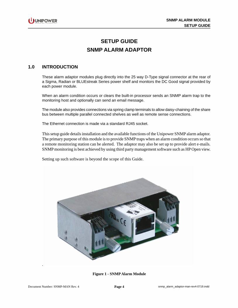
1.0 INTRODUCTION
These alarm adaptor modules plug directly into the 25 way D-Type signal connector at the rear of a Sigma, Radian or BLUEstreak Series power shelf and monitors the DC Good signal provided by each power module.
When an alarm condition occurs or clears the built-in processor sends an SNMP alarm trap to the monitoring host and optionally can send an email message.
The module also provides connections via spring clamp terminals to allow daisy-chaining of the share bus between multiple parallel connected shelves as well as remote sense connections.
The Ethernet connection is made via a standard RJ45 socket.
This setup guide details installation and the available functions of the Unipower SNMP alarm adaptor. The primary purpose of this module is to provide SNMP traps when an alarm condition occurs so that a remote monitoring station can be alerted. The adaptor may also be set up to provide alert e-mails. SNMP monitoring is best achieved by using third party management software such as HP Open view.
Setting up such software is beyond the scope of this Guide.
.
Figure 1 - SNMP Alarm Module
Page 5
SNMP ALARM MODULESETUP GUIDE
P O W E R I N G T E C H N O L O G Y
Document Number: SNMP-MAN Rev. 4 snmp_alarm_adaptor-man-rev4-0719.indd
2.0 STANDARD FEATURES
SNMP Alarm Traps Indicates DC Output Status for each Module Optional Email Alarms Daisy-chains Share Bus Provides Connections For Remote Sense Spring Clamp Connections (no tools)
3.0 WARRANTY (summary)
These adaptors are warranted for two (2) years from date of shipment against defects in material and workmanship. This warranty does not extend to products which have been opened, altered or repaired by persons other than persons authorized by the manufacturer or to products which become defective due to acts of God, negligence or the failure of customer to fully follow instructions with respect to installation, application or maintenance.
For a complete text of UNIPOWER’s warranty conditions please request a copy from your local Sales Office.
4.0 UNPACKING AND INSPECTION
4.1 This unit was carefully tested, inspected and packaged for shipment from our factory. Upon receipt the unit should be carefully unpacked and inspected for any damage in shipment.
4.2 If there is evidence of damage, do not attempt to install the unit. The freight carrier should be notified immediately and a claim for the cost of the unit should be filed with the carrier for direct reimbursement. Be sure to include the model and serial number of the damaged unit in all correspondence with the freight carrier. Also save the shipping carton and packing material as evidence of damage for the freight carrier’s inspection.
4.3 UNIPOWER LLC will cooperate fully in case of any shipping damage investigation.
4.4 Always save the packing materials for later use in shipping the unit. Never ship this unit without proper packing.
Page 6
SNMP ALARM MODULESETUP GUIDE
P O W E R I N G T E C H N O L O G Y
Document Number: SNMP-MAN Rev. 4 snmp_alarm_adaptor-man-rev4-0719.indd
5.0 MODULE SPECIFICATIONS
The following specifications are typical at 25°C unless otherwise noted.
NETWORK INTERFACEStandard .............................................................................................................................IEEE802.3Physical Layer ............................................................................................................. 10/100 Base-TData Rate ................................................................................................ 10/100Mbps (auto-sensing)Mode.....................................................................................Half/Full Duplex Support (auto-sensing)Connector .................................................................................RJ45, standard Ethernet connectionsSNMP ...................................................................................................................................Version 1
ENVIRONMENTALOperating Temp. Range ..............................................................................................-40°C to +70°CHumidity................................................................................................ 0% to 95%, Non-CondensingESD ..................................................................................Bellcore GR-1089-Core and EN61000-4-2MTBF, 35°C (Bellcore) ...................................................................................................... 1.6M Hours
PHYSICALCase Material ..............................................................................................................................SteelDimensions, Inches (mm) .....................................................1.14 H x 2.99 W x 2.24 D (29 x 76 x 57)Weight ..................................................................................................................... 0.22 lbs. (0.1 kg.)
6.0 DESCRIPTION
ETHERNETCONNECTION
RJ45
Sens
e +
Sens
e -
Shar
e
Sens
e +
Sens
e -
Shar
e
1 3 1 3
LinkStatus
NetworkActivity
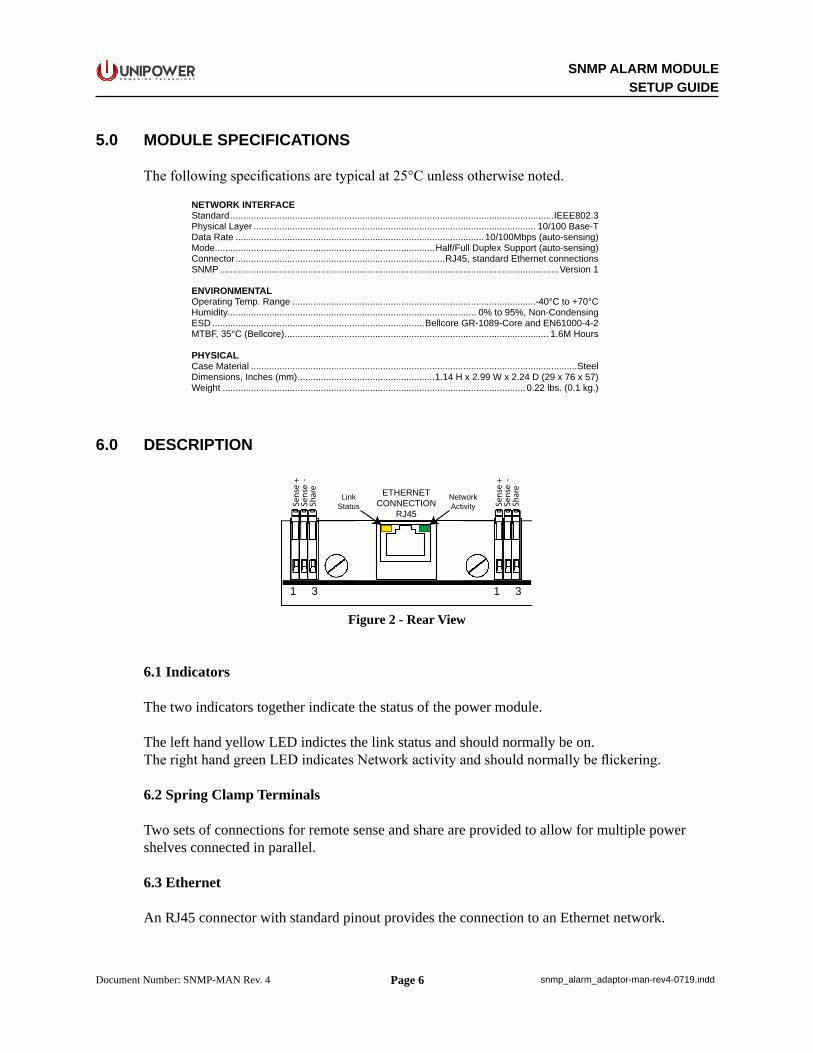
Figure 2 - Rear View
6.1 Indicators
The two indicators together indicate the status of the power module.
The left hand yellow LED indictes the link status and should normally be on.The right hand green LED indicates Network activity and should normally be flickering.
6.2 Spring Clamp Terminals
Two sets of connections for remote sense and share are provided to allow for multiple power shelves connected in parallel.
6.3 Ethernet
An RJ45 connector with standard pinout provides the connection to an Ethernet network.

Page 7
SNMP ALARM MODULESETUP GUIDE
P O W E R I N G T E C H N O L O G Y
Document Number: SNMP-MAN Rev. 4 snmp_alarm_adaptor-man-rev4-0719.indd
7.0 INSTALLATION
The adaptor is plugged directly into the 25 way D-type connector on the rear of the front-end / rectifier power shelf. The two knurled screws must be properly tightened to ensure mechanical stability.
When the remote sense facility is being used with multiple shelves it is recommended that the sense terminals are linked between individual shelves and only one pair of remote leads connected to the remote sense point.
In the case of dual bus shelves where there are two separate D-type connectors two separate adaptors are required to monitor the complete power system.
In such cases it is essential that the remote sense and share connections are made to the loads and the same bus on additional shelves.
The maximum wire size that can be accepted by the spring clamp terminals is 22AWG.
IMPORTANT NOTE: WHEN USING THESE ADAPTORS WITH THE OR BLUEstreak POWER SHELVES THE POSITION OF THE D-TYPE CONNECTORS ON THE REAR IS SUCH THAT THE ADAPTOR WILL PROTRUDE SLIGHTLY ABOVE THE TOP OF THE SHELF WHEN INSTALLED. THE POWER SHELF SHOULD THEREFORE BE INSTALLED IN THE RACK SUCH THAT ANY UNIT IN THE POSITION IMMEDIATELY ABOVE HAS A DEPTH LESS THAN OR EQUAL TO THAT OF THE POWER SHELF OTHERWISE THE ADAPTOR WILL NOT FIT.

Page 8
SNMP ALARM MODULESETUP GUIDE
P O W E R I N G T E C H N O L O G Y
Document Number: SNMP-MAN Rev. 4 snmp_alarm_adaptor-man-rev4-0719.indd
8.0 INITIAL SETUP
The module is intended to be connected to a local area network using ethernet. The module provides an RJ-45 socket for this purpose.
To assist in setting up the module initially, it is suggested that a crossover cable is used to connect directly between the module and a computer.
The module is initially set with the following network settings:
IP address: 192.168.0.200 Subnet mask: 255.255.255.0 Gateway: 0.0.0.0
A computer initially connected to the module must have it’s IP address set in the range 192.168.0.x where x is 1 to 255 (not 200 though). The computers subnet mask must be set to 255.255.255.0.
It should then be possible to log in to the module using internet explorer or another web browser.
The rectifier shelf system should be powered up with the SNMP module connected to the 25-way connector on the rear of the shelf. You should see the yellow and green lights on the SNMP module flash a few times as it boots up.
To connect to the module, simply type the following into the browsers address bar:
http://192.168.0.200
The log in web page should appear. If it does not, please recheck your computer network settings and ensure that a crossover cable is used for direct connection.

Page 9
SNMP ALARM MODULESETUP GUIDE
P O W E R I N G T E C H N O L O G Y
Document Number: SNMP-MAN Rev. 4 snmp_alarm_adaptor-man-rev4-0719.indd
9.0 WEB PAGES
9.1 Initial Log On
Figure 3 - Initial Log On Page
Type the following into the boxes as shown in figure 1 to log on:
Username: adminPassword: 1234
Press the Login button.
Page 10
SNMP ALARM MODULESETUP GUIDE
P O W E R I N G T E C H N O L O G Y
Document Number: SNMP-MAN Rev. 4 snmp_alarm_adaptor-man-rev4-0719.indd
9.2 Home Page
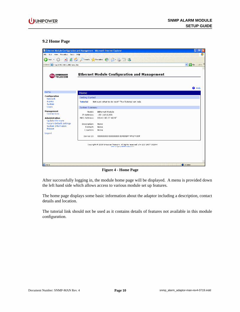
Figure 4 - Home Page
After successfully logging in, the module home page will be displayed. A menu is provided down the left hand side which allows access to various module set up features.
The home page displays some basic information about the adaptor including a description, contact details and location.
The tutorial link should not be used as it contains details of features not available in this module configuration.
Page 11
SNMP ALARM MODULESETUP GUIDE
P O W E R I N G T E C H N O L O G Y
Document Number: SNMP-MAN Rev. 4 snmp_alarm_adaptor-man-rev4-0719.indd
9.3 Configuration – Network – IP Settings
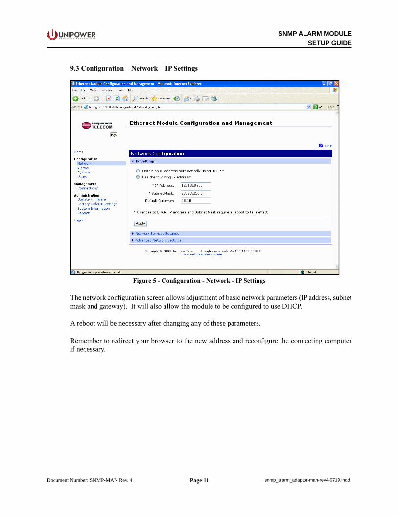
Figure 5 - Configuration - Network - IP Settings
The network configuration screen allows adjustment of basic network parameters (IP address, subnet mask and gateway). It will also allow the module to be configured to use DHCP.
A reboot will be necessary after changing any of these parameters.
Remember to redirect your browser to the new address and reconfigure the connecting computer if necessary.
Page 12
SNMP ALARM MODULESETUP GUIDE
P O W E R I N G T E C H N O L O G Y
Document Number: SNMP-MAN Rev. 4 snmp_alarm_adaptor-man-rev4-0719.indd
9.4 Configuration – Network – Network Services Settings
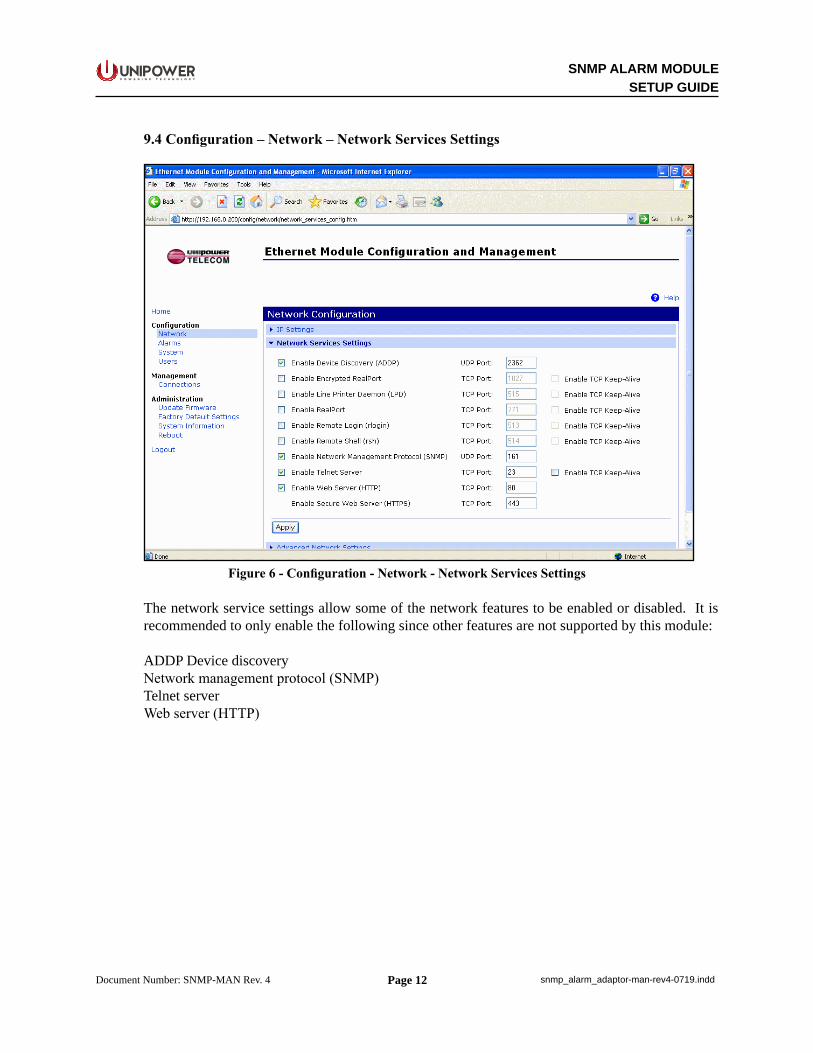
Figure 6 - Configuration - Network - Network Services Settings
The network service settings allow some of the network features to be enabled or disabled. It is recommended to only enable the following since other features are not supported by this module:
ADDP Device discoveryNetwork management protocol (SNMP)Telnet serverWeb server (HTTP)
Page 13
SNMP ALARM MODULESETUP GUIDE
P O W E R I N G T E C H N O L O G Y
Document Number: SNMP-MAN Rev. 4 snmp_alarm_adaptor-man-rev4-0719.indd
9.5 Configuration – Network – Advanced Network Settings
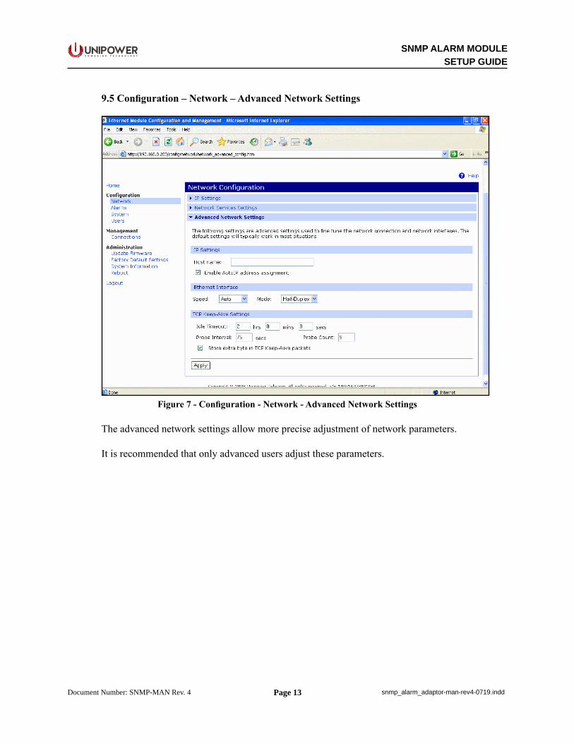
Figure 7 - Configuration - Network - Advanced Network Settings
The advanced network settings allow more precise adjustment of network parameters.
It is recommended that only advanced users adjust these parameters.
Page 14
SNMP ALARM MODULESETUP GUIDE
P O W E R I N G T E C H N O L O G Y
Document Number: SNMP-MAN Rev. 4 snmp_alarm_adaptor-man-rev4-0719.indd
9.6 Configuration - Alarms Configuration
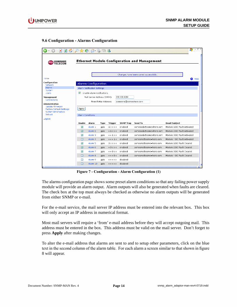
Figure 7 - Configuration - Alarm Configuration (1)
The alarms configuration page shows some preset alarm conditions so that any failing power supply module will provide an alarm output. Alarm outputs will also be generated when faults are cleared. The check box at the top must always be checked as otherwise no alarm outputs will be generated from either SNMP or e-mail.
For the e-mail service, the mail server IP address must be entered into the relevant box. This box will only accept an IP address in numerical format.
Most mail servers will require a ‘from’ e-mail address before they will accept outgoing mail. This address must be entered in the box. This address must be valid on the mail server. Don’t forget to press Apply after making changes.
To alter the e-mail address that alarms are sent to and to setup other parameters, click on the blue text in the second column of the alarm table. For each alarm a screen similar to that shown in figure 8 will appear.

Page 15
SNMP ALARM MODULESETUP GUIDE
P O W E R I N G T E C H N O L O G Y
Document Number: SNMP-MAN Rev. 4 snmp_alarm_adaptor-man-rev4-0719.indd
Figure 8 - Configuration - Alarm Configuration (2)
The GPIO pin state combo boxes should not be altered as this will affect how the module creates alarms. If reminders at regular intervals are required for a continuing alarm condition, then this can be enabled using the check box. The repeat time in seconds can then be entered into the box.
If an e-mail is required to be sent for this condition, then the check box must be checked next to ‘Send E-mail to the following recipients when alarm occurs’.
The text boxes can then be filled in with the relevant details.
Note that the e-mail subject is also used when SNMP traps are sent.
To enable an SNMP trap to be sent, make sure the check box is checked for that option.
Please press Apply when all changes are complete.
Page 16
SNMP ALARM MODULESETUP GUIDE
P O W E R I N G T E C H N O L O G Y
Document Number: SNMP-MAN Rev. 4 snmp_alarm_adaptor-man-rev4-0719.indd
9.7 Configuration – System - System Configuration
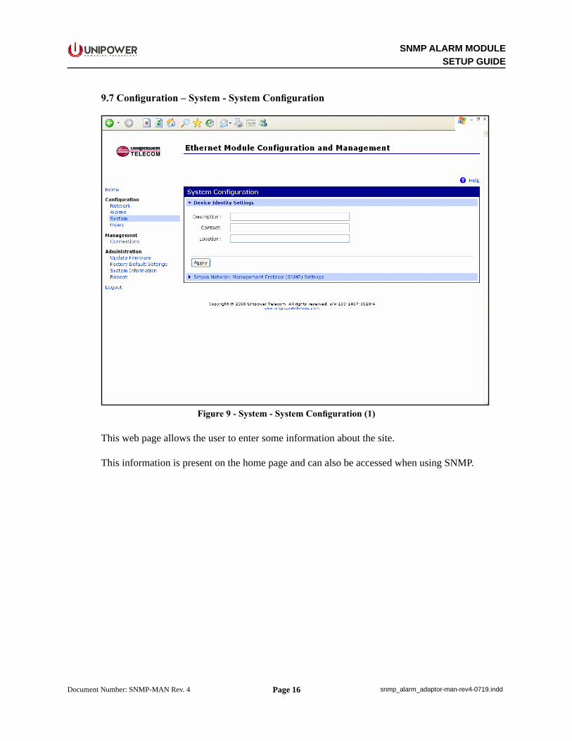
Figure 9 - System - System Configuration (1)
This web page allows the user to enter some information about the site.
This information is present on the home page and can also be accessed when using SNMP.
Page 17
SNMP ALARM MODULESETUP GUIDE
P O W E R I N G T E C H N O L O G Y
Document Number: SNMP-MAN Rev. 4 snmp_alarm_adaptor-man-rev4-0719.indd
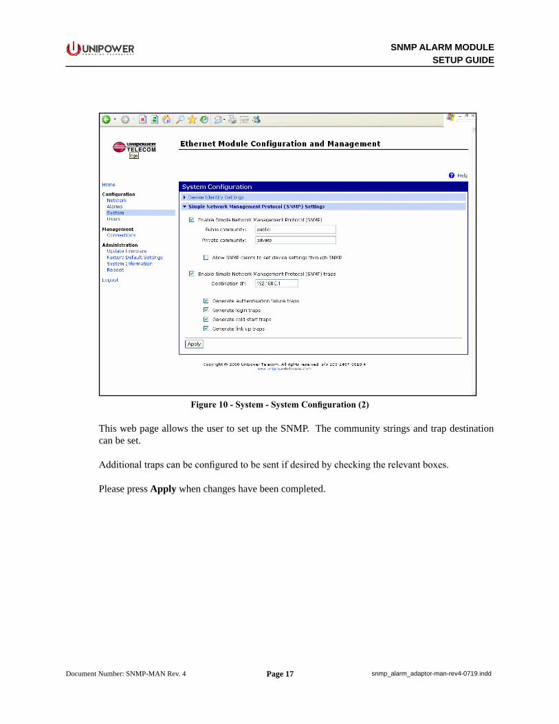
Figure 10 - System - System Configuration (2)
This web page allows the user to set up the SNMP. The community strings and trap destination can be set.
Additional traps can be configured to be sent if desired by checking the relevant boxes.
Please press Apply when changes have been completed.
Page 18
SNMP ALARM MODULESETUP GUIDE
P O W E R I N G T E C H N O L O G Y
Document Number: SNMP-MAN Rev. 4 snmp_alarm_adaptor-man-rev4-0719.indd
9.8 Configuration – Users
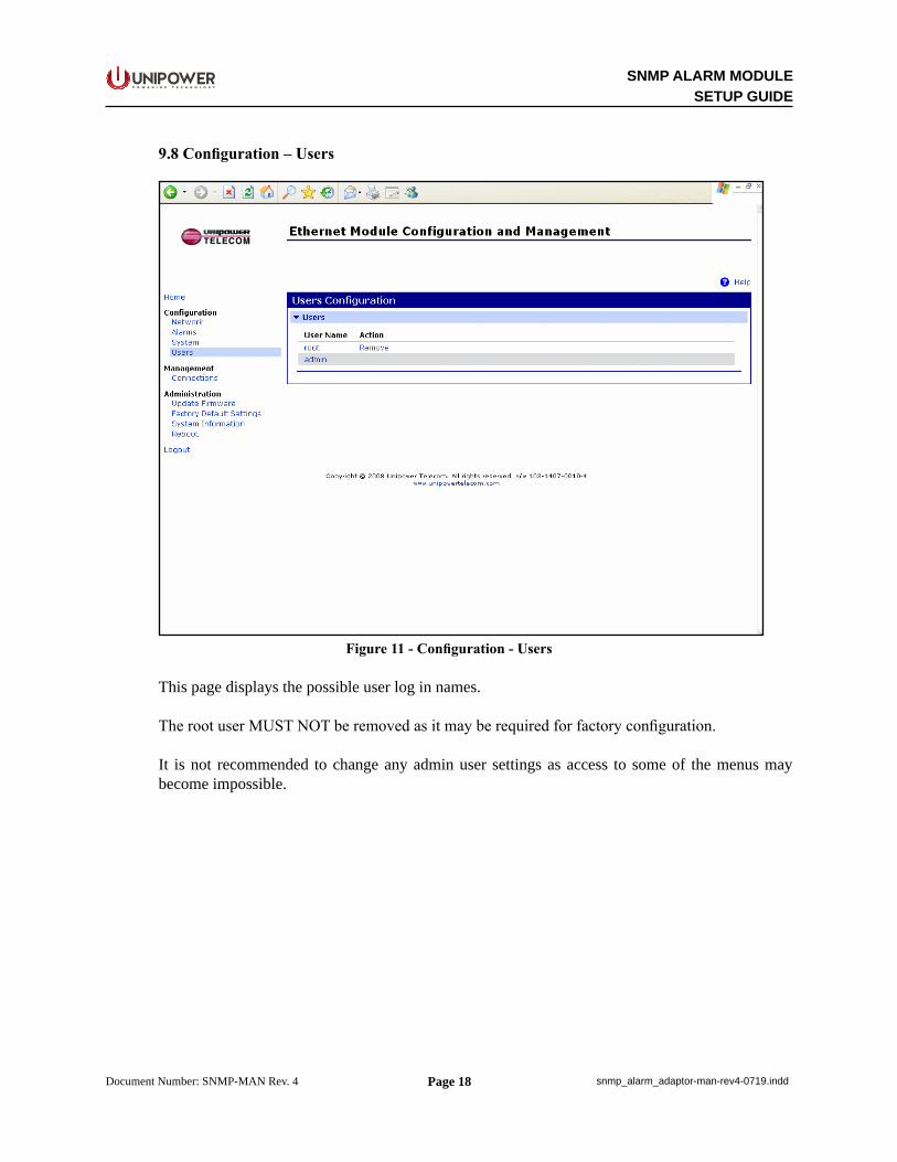
Figure 11 - Configuration - Users
This page displays the possible user log in names.
The root user MUST NOT be removed as it may be required for factory configuration.
It is not recommended to change any admin user settings as access to some of the menus may become impossible.
Page 19
SNMP ALARM MODULESETUP GUIDE
P O W E R I N G T E C H N O L O G Y
Document Number: SNMP-MAN Rev. 4 snmp_alarm_adaptor-man-rev4-0719.indd
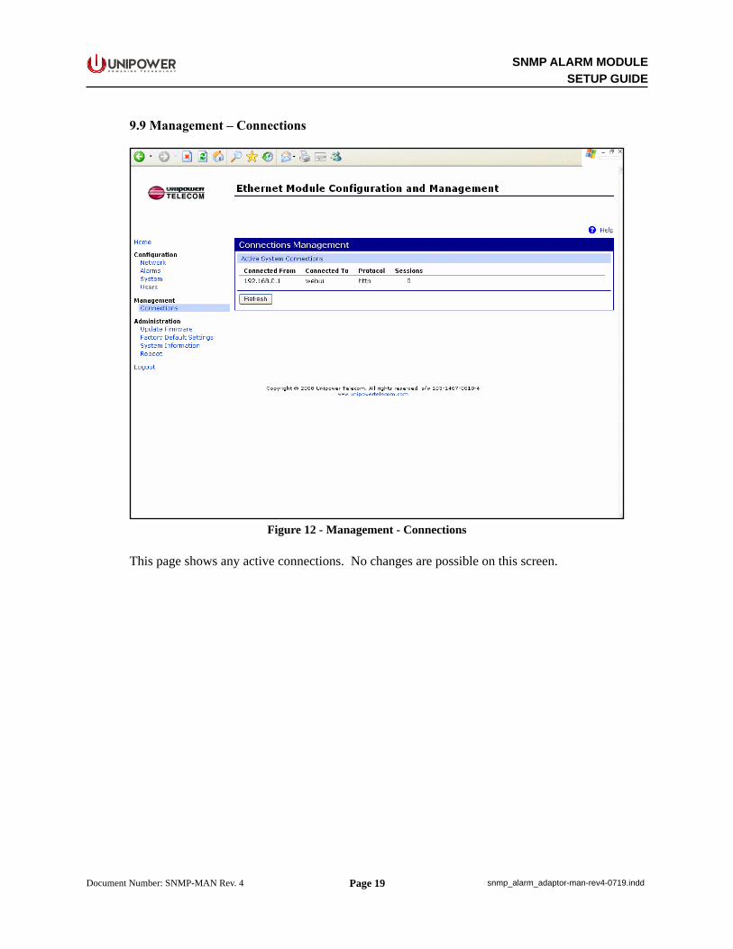
9.9 Management – Connections
Figure 12 - Management - Connections
This page shows any active connections. No changes are possible on this screen.

Page 20
SNMP ALARM MODULESETUP GUIDE
P O W E R I N G T E C H N O L O G Y
Document Number: SNMP-MAN Rev. 4 snmp_alarm_adaptor-man-rev4-0719.indd
9.10 Administration – Update Firmware
Figure 13 - Administration - Update Firmware
This page allows the updating of the core module firmware.
It is not recommended to do this unless it has been advised by UNIPOWER. If so then the necessary files will be provided.
Page 21
SNMP ALARM MODULESETUP GUIDE
P O W E R I N G T E C H N O L O G Y
Document Number: SNMP-MAN Rev. 4 snmp_alarm_adaptor-man-rev4-0719.indd
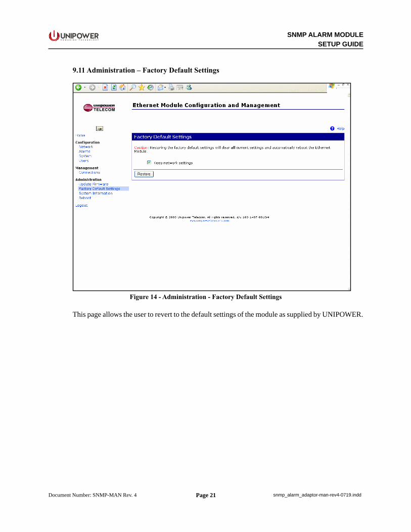
9.11 Administration – Factory Default Settings
Figure 14 - Administration - Factory Default Settings
This page allows the user to revert to the default settings of the module as supplied by UNIPOWER.
Page 22
SNMP ALARM MODULESETUP GUIDE
P O W E R I N G T E C H N O L O G Y
Document Number: SNMP-MAN Rev. 4 snmp_alarm_adaptor-man-rev4-0719.indd
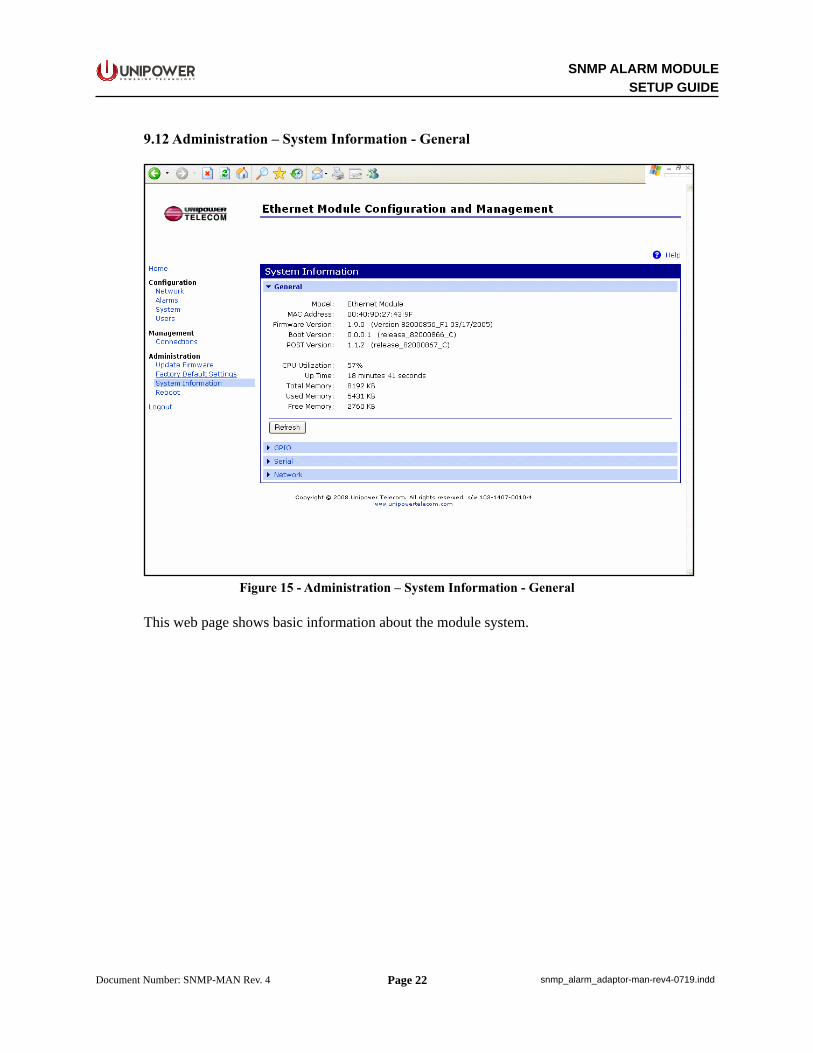
9.12 Administration – System Information - General
Figure 15 - Administration – System Information - General
This web page shows basic information about the module system.

Page 23
SNMP ALARM MODULESETUP GUIDE
P O W E R I N G T E C H N O L O G Y
Document Number: SNMP-MAN Rev. 4 snmp_alarm_adaptor-man-rev4-0719.indd
9.13 Administration – System Information – GPIO
Figure 16 - Administration – System Information – GPIO
The GPIO page shows the state of the monitored inputs. Each pin corresponds to a DCOK signal from a power supply module. In TPCP/TPCM and similar products where three power modules are monitored, then the first three pins will be used for modules 1 to 3 as viewed from the front of the shelf. When a module is working correctly, the pin will show as De-asserted. For modules that are faulty or are not present, the pin will show as Asserted.
Page 24
SNMP ALARM MODULESETUP GUIDE
P O W E R I N G T E C H N O L O G Y
Document Number: SNMP-MAN Rev. 4 snmp_alarm_adaptor-man-rev4-0719.indd
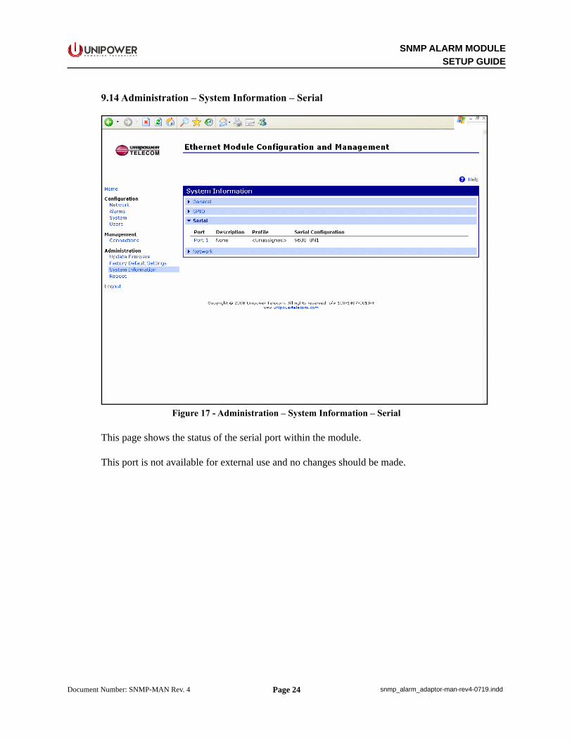
9.14 Administration – System Information – Serial
Figure 17 - Administration – System Information – Serial
This page shows the status of the serial port within the module.
This port is not available for external use and no changes should be made.
Page 25
SNMP ALARM MODULESETUP GUIDE
P O W E R I N G T E C H N O L O G Y
Document Number: SNMP-MAN Rev. 4 snmp_alarm_adaptor-man-rev4-0719.indd
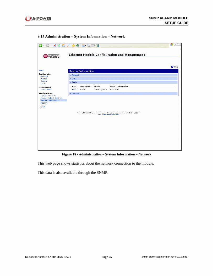
9.15 Administration – System Information – Network
Figure 18 - Administration – System Information – Network
This web page shows statistics about the network connection to the module.
This data is also available through the SNMP.

Page 26
SNMP ALARM MODULESETUP GUIDE
P O W E R I N G T E C H N O L O G Y
Document Number: SNMP-MAN Rev. 4 snmp_alarm_adaptor-man-rev4-0719.indd
9.16 Administration – Reboot
Figure 19 - Administration – Reboot
This page is used to reboot the module.
This can be done if some changes have been made that require it.
Page 27
SNMP ALARM MODULESETUP GUIDE
P O W E R I N G T E C H N O L O G Y
Document Number: SNMP-MAN Rev. 4 snmp_alarm_adaptor-man-rev4-0719.indd
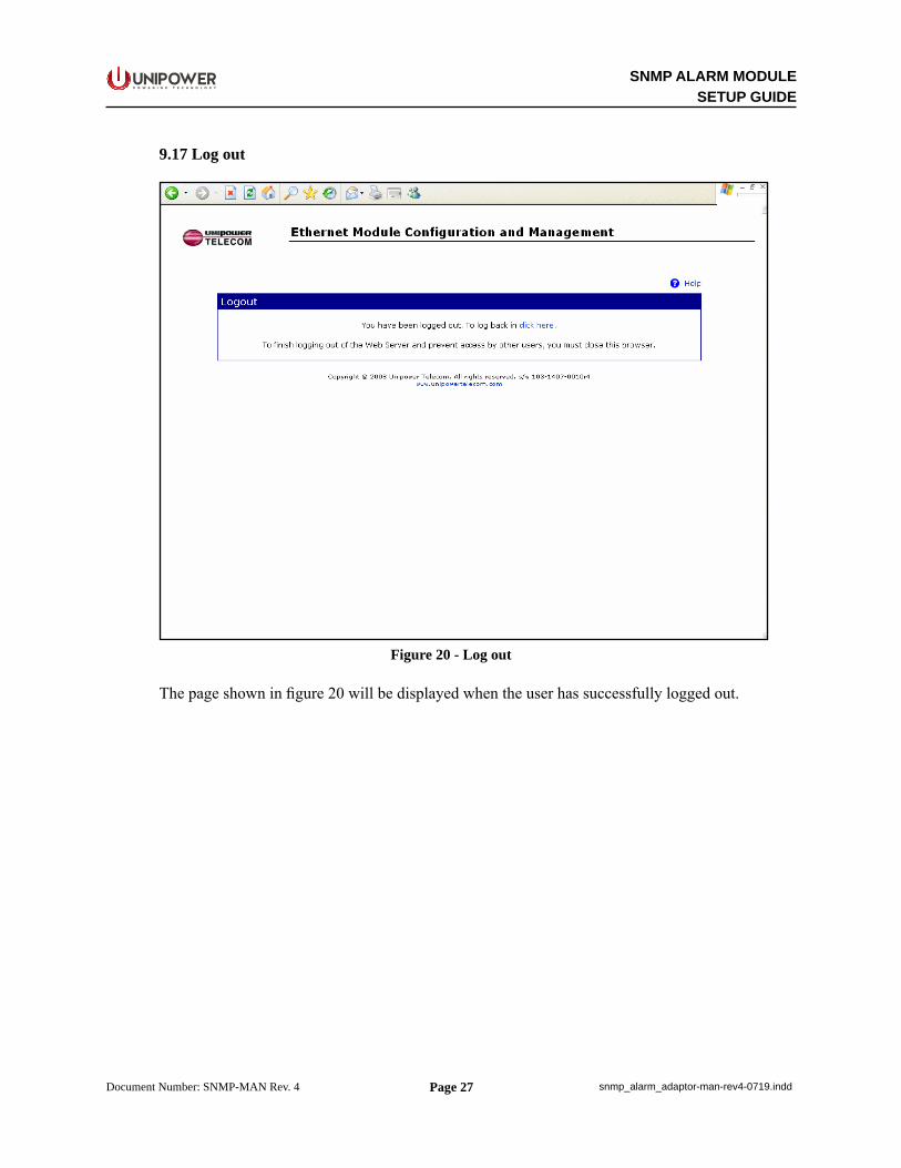
9.17 Log out
Figure 20 - Log out
The page shown in figure 20 will be displayed when the user has successfully logged out.

Page 28
SNMP ALARM MODULESETUP GUIDE
P O W E R I N G T E C H N O L O G Y
Document Number: SNMP-MAN Rev. 4 snmp_alarm_adaptor-man-rev4-0719.indd
This document is believed to be correct at time of publication and UNIPOWER LLC accepts no responsibility for consequences from printing errors or inaccuracies. Specifications are subject to change without notice.
9.18 Further SNMP information
The SNMP adaptor supports SNMP version 1.
The following MIBs should be used with the SNMP adaptor:
RFC1213, MIB-II Network StatisticsRFCs 1316, 1317 Port StatisticsDIGI-SMI Enterprise MIBDIGI-DEVICE-INFO-MIB Enterprise MIBDIGI-SERIAL-ALARM-TRAPS-MIB Enterprise MIB
For more information on the statistics available through the standard RFCs listed above, refer to the RFCs available on the IETF web site (www.ietf.org). For enterprise MIBs, refer to the description fields in the MIB text.