chapter 20, snmp - cisco€¦ · chapter 20 snmp 20.1 snmp overview information for generic ds-1,...
TRANSCRIPT
78-18887-02
C H A P T E R 20
SNMPThis chapter explains Simple Network Management Protocol (SNMP) as implemented by the Cisco ONS 15454.
For SNMP setup information, refer to the Cisco ONS 15454 DWDM Procedure Guide.
Note Unless otherwise specified, “ONS 15454” refers to both ANSI and ETSI shelf assemblies.
Chapter topics include:
• 20.1 SNMP Overview, page 20-1
• 20.2 Basic SNMP Components, page 20-3
• 20.3 SNMP External Interface Requirement, page 20-4
• 20.4 SNMP Version Support, page 20-4
• 20.5 SNMP Message Types, page 20-5
• 20.6 SNMP Management Information Bases, page 20-6
• 20.7 SNMP Trap Content, page 20-14
• 20.8 SNMPv1/v2 Community Names, page 20-22
• 20.9 SNMP in Multishelf Management, page 20-22
• 20.10 SNMPv1/v2 Proxy Over Firewalls, page 20-24
• 20.11 SNMPv3 Proxy Configuration, page 20-25
• 20.12 Remote Monitoring, page 20-25
20.1 SNMP Overview SNMP is an application-layer communication protocol that allows ONS 15454 network devices to exchange management information among these systems and with other devices outside the network. Through SNMP, network administrators can manage network performance, find and solve network problems, and plan network growth. Up to 10 SNMP trap destinations and five concurrent Cisco Transport Controller (CTC) user sessions are allowed per node.
The ONS 15454 uses SNMP for asynchronous event notification to a network management system (NMS). ONS SNMP implementation uses standard Internet Engineering Task Force (IETF) management information bases (MIBs) to convey node-level inventory, fault, and performance management
20-1Cisco ONS 15454 DWDM Reference Manual, R9.1

Chapter 20 SNMP20.1 SNMP Overview
information for generic DS-1, DS-3, SONET, and Ethernet read-only management. SNMP allows a generic SNMP manager such as HP OpenView Network Node Manager (NNM) or Open Systems Interconnection (OSI) NetExpert to be utilized for limited management functions.
The Cisco ONS 15454 supports SNMP Version 1 (SNMPv1), SNMP Version 2c (SNMPv2c), and SNMP Version 3 (SNMPv3). As compared to SNMPv1, SNMPv2c includes additional protocol operations and 64-bit performance monitoring support. SNMPv3 provides authentication, encryption, and message integrity and is more secure. This chapter describes the SNMP versions and describes the configuration parameters for the ONS 15454.
Note It is recommended that the SNMP Manager timeout value be set to 60 seconds. Under certain conditions, if this value is lower than the recommended time, the TCC card can reset. However, the response time depends on various parameters such as object being queried, complexity, and number of hops in the node, etc.
Note In Software Release 8.0 and later, you can retrieve automatic in service (AINS) state and soak time through the SNMP and Transaction Language One (TL1) interfaces.
Note The CERENT-MSDWDM-MIB.mib, CERENT-FC-MIB.mib, and CERENT-GENERIC-PM-MIB.mib in the CiscoV2 directory support 64-bit performance monitoring counters. The SNMPv1 MIB in the CiscoV1 directory does not contain 64-bit performance monitoring counters, but supports the lower and higher word values of the corresponding 64-bit counter. The other MIB files in the CiscoV1 and CiscoV2 directories are identical in content and differ only in format.
The SNMP management interface supports the IEEE 802.3 LAG MIB.
Figure 20-1 illustrates the basic layout idea of an SNMP-managed network.
Figure 20-1 Basic Network Managed by SNMP
5258
2
20-2Cisco ONS 15454 DWDM Reference Manual, R9.1
78-18887-02

Chapter 20 SNMP20.2 Basic SNMP Components
20.2 Basic SNMP ComponentsIn general terms, an SNMP-managed network consists of a management system, agents, and managed devices.
A management system such as HP OpenView executes monitoring applications and controls managed devices. Management systems execute most of the management processes and provide the bulk of memory resources used for network management. A network might be managed by one or several management systems. Figure 20-2 illustrates the relationship between the network manager, the SNMP agent, and the managed devices.
Figure 20-2 Example of the Primary SNMP Components
An agent (such as SNMP) residing on each managed device translates local management information data—such as performance information or event and error information—caught in software traps, into a readable form for the management system. Figure 20-3 illustrates SNMP agent get-requests that transport data to the network management software.
ManagementEntity
Agent
ManagementDatabase
Agent
NMS
ManagementDatabase
Managed Devices
Agent
ManagementDatabase
3393
0
20-3Cisco ONS 15454 DWDM Reference Manual, R9.1
78-18887-02

Chapter 20 SNMP20.3 SNMP External Interface Requirement
Figure 20-3 Agent Gathering Data from a MIB and Sending Traps to the Manager
The SNMP agent captures data from MIBs, which are device parameter and network data repositories, or from error or change traps.
A managed element—such as a router, access server, switch, bridge, hub, computer host, or network element (such as an ONS 15454)—is accessed through the SNMP agent. Managed devices collect and store management information, making it available through SNMP to other management systems having the same protocol compatibility.
20.3 SNMP External Interface RequirementSince all SNMP requests come from a third-party application, the only external interface requirement is that a third-party SNMP client application can upload RFC 3273 SNMP MIB variables in the etherStatsHighCapacityTable, etherHistoryHighCapacityTable, or mediaIndependentTable.
20.4 SNMP Version SupportThe ONS 15454 supports SNMPv1 and SNMPv2c traps and get requests. The ONS 15454 SNMP MIBs define alarms, traps, and status. Through SNMP, NMS applications can query a management agent for data from functional entities such as Ethernet switches and SONET multiplexers using a supported MIB.
Note ONS 15454 MIB files in the CiscoV1 and CiscoV2 directories are almost identical in content except for the difference in 64-bit performance monitoring features. The CiscoV2 directory contains three MIBs with 64-bit performance monitoring counters:. CERENT-MSDWDM-MIB.mib, CERENT-FC-MIB.mib, and CERENT-GENERIC-PM-MIB.mib The CiscoV1 directory does not contain any 64-bit counters, but it does support the lower and higher word values used in 64-bit counters. The two directories also have somewhat different formats.
20.4.1 SNMPv3 SupportCisco ONS 15454 Software R9.0 and later supports SNMPv3 in addition to SNMPv1 and SNMPv2c. SNMPv3 is an interoperable standards-based protocol for network management. SNMPv3 provides secure access to devices by a combination of authentication and encryption packets over the network based on the User Based Security Model (USM) and the View-Based Access Control Model (VACM).
• User-Based Security Model—The User-Based Security Model (USM) uses the HMAC algorithm for generating keys for authentication and privacy. SNMPv3 authenticates data based on its origin, and ensures that the data is received intact. SNMPv1 and v2 authenticate data based on the plain text community string, which is less secure when compared to the user-based authentication model.
get, get-next, get-bulkNetwork device
get-response, traps
3263
2SNMP Manager
NMS
MIBSNMP Agent
20-4Cisco ONS 15454 DWDM Reference Manual, R9.1
78-18887-02

Chapter 20 SNMP20.5 SNMP Message Types
• View-Based Access Control Model—The view-based access control model controls the access to the managed objects. RFC 3415 defines the following five elements that VACM comprises:
– Groups—A set of users on whose behalf the MIB objects can be accessed. Each user belongs to a group. The group defines the access policy, notifications that users can receive, and the security model and security level for the users.
– Security level—The access rights of a group depend on the security level of the request.
– Contexts—Define a named subset of the object instances in the MIB. MIB objects are grouped into collections with different access policies based on the MIB contexts.
– MIB views—Define a set of managed objects as subtrees and families. A view is a collection or family of subtrees. Each subtree is included or excluded from the view.
– Access policy—Access is determined by the identity of the user, security level, security model, context, and the type of access (read/write). The access policy defines what SNMP objects can be accessed for reading, writing, and creating.
Access to information can be restricted based on these elements. Each view is created with different access control details. An operation is permitted or denied based on the access control details.
You can configure SNMPv3 on a node to allow SNMP get and set access to management information and configure a node to send SNMPv3 traps to trap destinations in a secure way. SNMPv3 can be configured in secure mode, non-secure mode, or disabled mode.
SNMP, when configured in secure mode, only allows SNMPv3 messages that have the authPriv security level. SNMP messages without authentication or privacy enabled are not allowed. When SNMP is configured in non-secure mode, it allows SNMPv1, SNMPv2, and SNMPv3 message types.
20.5 SNMP Message TypesThe ONS 15454 SNMP agent communicates with an SNMP management application using SNMP messages. Table 20-1 describes these messages.
Table 20-1 ONS 15454 SNMP Message Types
Operation Description
get-request Retrieves a value from a specific variable.
get-next-request Retrieves the value following the named variable; this operation is often used to retrieve variables from within a table. With this operation, an SNMP manager does not need to know the exact variable name. The SNMP manager searches sequentially to find the needed variable from within the MIB.
get-response Replies to a get-request, get-next-request, get-bulk-request, or set-request sent by an NMS.
get-bulk-request Fills the get-response with up to the max-repetition number of get-next interactions, similar to a get-next-request.
set-request Provides remote network monitoring (RMON) MIB.
trap Indicates that an event has occurred. An unsolicited message is sent by an SNMP agent to an SNMP manager.
20-5Cisco ONS 15454 DWDM Reference Manual, R9.1
78-18887-02
Chapter 20 SNMP20.6 SNMP Management Information Bases
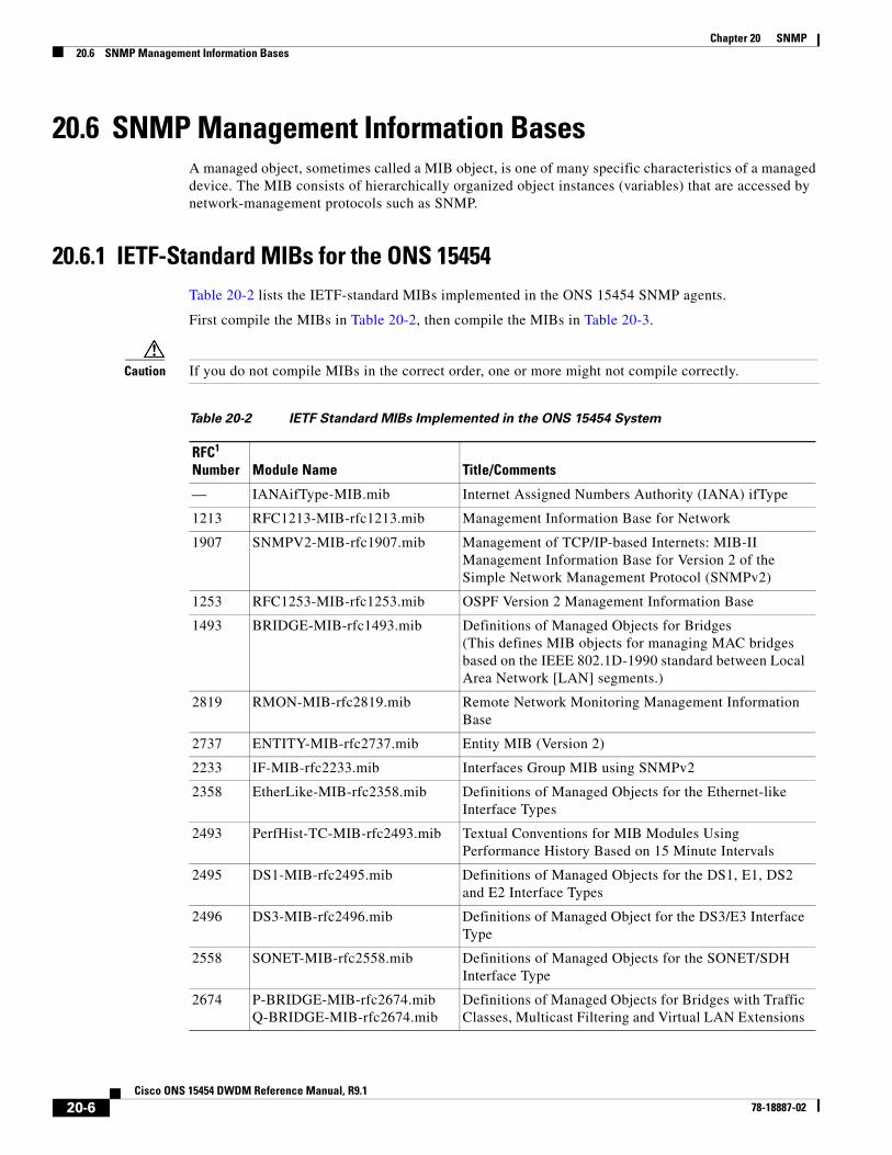
20.6 SNMP Management Information BasesA managed object, sometimes called a MIB object, is one of many specific characteristics of a managed device. The MIB consists of hierarchically organized object instances (variables) that are accessed by network-management protocols such as SNMP.
20.6.1 IETF-Standard MIBs for the ONS 15454Table 20-2 lists the IETF-standard MIBs implemented in the ONS 15454 SNMP agents.
First compile the MIBs in Table 20-2, then compile the MIBs in Table 20-3.
Caution If you do not compile MIBs in the correct order, one or more might not compile correctly.
Table 20-2 IETF Standard MIBs Implemented in the ONS 15454 System
RFC1 Number Module Name Title/Comments
— IANAifType-MIB.mib Internet Assigned Numbers Authority (IANA) ifType
1213 RFC1213-MIB-rfc1213.mib Management Information Base for Network
1907 SNMPV2-MIB-rfc1907.mib Management of TCP/IP-based Internets: MIB-II Management Information Base for Version 2 of the Simple Network Management Protocol (SNMPv2)
1253 RFC1253-MIB-rfc1253.mib OSPF Version 2 Management Information Base
1493 BRIDGE-MIB-rfc1493.mib Definitions of Managed Objects for Bridges (This defines MIB objects for managing MAC bridges based on the IEEE 802.1D-1990 standard between Local Area Network [LAN] segments.)
2819 RMON-MIB-rfc2819.mib Remote Network Monitoring Management Information Base
2737 ENTITY-MIB-rfc2737.mib Entity MIB (Version 2)
2233 IF-MIB-rfc2233.mib Interfaces Group MIB using SNMPv2
2358 EtherLike-MIB-rfc2358.mib Definitions of Managed Objects for the Ethernet-like Interface Types
2493 PerfHist-TC-MIB-rfc2493.mib Textual Conventions for MIB Modules Using Performance History Based on 15 Minute Intervals
2495 DS1-MIB-rfc2495.mib Definitions of Managed Objects for the DS1, E1, DS2 and E2 Interface Types
2496 DS3-MIB-rfc2496.mib Definitions of Managed Object for the DS3/E3 Interface Type
2558 SONET-MIB-rfc2558.mib Definitions of Managed Objects for the SONET/SDH Interface Type
2674 P-BRIDGE-MIB-rfc2674.mib Q-BRIDGE-MIB-rfc2674.mib
Definitions of Managed Objects for Bridges with Traffic Classes, Multicast Filtering and Virtual LAN Extensions
20-6Cisco ONS 15454 DWDM Reference Manual, R9.1
78-18887-02

Chapter 20 SNMP20.6.2 Proprietary ONS 15454 MIBs
20.6.2 Proprietary ONS 15454 MIBsEach ONS 15454 is shipped with a software CD containing applicable proprietary MIBs. Table 20-3 lists the proprietary MIBs for the ONS 15454.
3273 HC-RMON-MIB The MIB module for managing remote monitoring device implementations, augmenting the original RMON MIB as specified in RFC 2819 and RFC 1513 and RMON-2 MIB as specified in RFC 2021
CISCO-DOT3-OAM-MIB A Cisco proprietary MIB defined for IEEE 802.3ah ethernet OAM.
3413 SNMP-NOTIFICATION-MIB Defines the MIB objects that provide mechanisms to remotely configure the parameters used by an SNMP entity for generating notifications.
3413 SNMP-TARGET-MIB Defines the MIB objects that provide mechanisms to remotely configure the parameters that are used by an SNMP entity for generating SNMP messages.
3413 SNMP-PROXY-MIB Defines MIB objects that provide mechanisms to remotely configure the parameters used by a proxy forwarding application.
3414 SNMP-USER-BASED-SM-MIB The management information definitions for the SNMP User-Based Security Model.
3415 SNMP-VIEW-BASED-ACM-MIB
The management information definitions for the View-Based Access Control Model for SNMP.
1. RFC = Request for Comment
Table 20-2 IETF Standard MIBs Implemented in the ONS 15454 System (continued)
RFC1 Number Module Name Title/Comments
Table 20-3 ONS 15454 Proprietary MIBs
MIB Number Module Name
1 CERENT-GLOBAL-REGISTRY.mib
2 CERENT-TC.mib
3 CERENT-454.mib
4 CERENT-GENERIC.mib (not applicable to ONS 15454)
5 CISCO-SMI.mib
6 CISCO-VOA-MIB.mib
7 CERENT-MSDWDM-MIB.mib
8 CERENT-OPTICAL-MONITOR-MIB.mib
9 CERENT-HC-RMON-MIB.mib
10 CERENT-ENVMON-MIB.mib
11 CERENT-GENERIC-PM-MIB.mib
20-7Cisco ONS 15454 DWDM Reference Manual, R9.1
78-18887-02

Chapter 20 SNMP20.6.2 Proprietary ONS 15454 MIBs
12 BRIDGE-MIB.my
13 CERENT-454-MIB.mib
14 CERENT-ENVMON-MIB.mib
15 CERENT-FC-MIB.mib
16 CERENT-GENERIC-MIB.mib
17 CERENT-GENERIC-PM-MIB.mib
18 CERENT-GLOBAL-REGISTRY.mib
19 CERENT-HC-RMON-MIB.mib
20 CERENT-IF-EXT-MIB.mib
21 CERENT-MSDWDM-MIB.mib
22 CERENT-OPTICAL-MONITOR-MIB.mib
23 CERENT-TC.mib
24 CISCO-IGMP-SNOOPING-MIB.mib
25 CISCO-OPTICAL-MONITOR-MIB.mib
26 CISCO-OPTICAL-PATCH-MIB.mib
27 CISCO-SMI.mib
28 CISCO-VOA-MIB.mib
29 CISCO-VTP-MIB.mib
30 INET-ADDRESS-MIB.mib
31 OLD-CISCO-TCP-MIB.my
32 OLD-CISCO-TS-MIB.my
33 RFC1155-SMI.my
34 RFC1213-MIB.my
35 RFC1315-MIB.my
36 BGP4-MIB.my
37 CERENT-454-MIB.mib
38 CERENT-ENVMON-MIB.mib
39 CERENT-FC-MIB.mib
40 CERENT-GENERIC-MIB.mib
41 CERENT-GENERIC-PM-MIB.mib
42 CERENT-GLOBAL-REGISTRY.mib
43 CERENT-HC-RMON-MIB.mib
44 CERENT-IF-EXT-MIB.mib
45 CERENT-MSDWDM-MIB.mib
46 CERENT-OPTICAL-MONITOR-MIB.mib
Table 20-3 ONS 15454 Proprietary MIBs
MIB Number Module Name
20-8Cisco ONS 15454 DWDM Reference Manual, R9.1
78-18887-02

Chapter 20 SNMP20.6.2 Proprietary ONS 15454 MIBs
47 CERENT-TC.mib
48 CISCO-CDP-MIB.my
49 CISCO-CLASS-BASED-QOS-MIB.my
50 CISCO-CONFIG-COPY-MIB.my
51 CISCO-CONFIG-MAN-MIB.my
52 CISCO-ENTITY-ASSET-MIB.my
53 CISCO-ENTITY-EXT-MIB.my
54 CISCO-ENTITY-VENDORTYPE-OID-MI
55 CISCO-FRAME-RELAY-MIB.my
56 CISCO-FTP-CLIENT-MIB.my
57 CISCO-HSRP-EXT-MIB.my
58 CISCO-HSRP-MIB.my
59 CISCO-IGMP-SNOOPING-MIB.mib
60 CISCO-IMAGE-MIB.my
61 CISCO-IP-STAT-MIB.my
62 CISCO-IPMROUTE-MIB.my
63 CISCO-MEMORY-POOL-MIB.my
64 CISCO-OPTICAL-MONITOR-MIB.mib
65 CISCO-OPTICAL-PATCH-MIB.mib
66 CISCO-PING-MIB.my
67 CISCO-PORT-QOS-MIB.my
68 CISCO-PROCESS-MIB.my
69 CISCO-PRODUCTS-MIB.my
70 CISCO-RTTMON-MIB.my
71 CISCO-SMI.mib
72 CISCO-SMI.my
73 CISCO-SYSLOG-MIB.my
74 CISCO-TC.my
75 CISCO-TCP-MIB.my
76 CISCO-VLAN-IFTABLE-RELATIONSHI
77 CISCO-VOA-MIB.mib
78 CISCO-VTP-MIB.mib
79 CISCO-VTP-MIB.my
80 ENTITY-MIB.my
81 ETHERLIKE-MIB.my
Table 20-3 ONS 15454 Proprietary MIBs
MIB Number Module Name
20-9Cisco ONS 15454 DWDM Reference Manual, R9.1
78-18887-02

Chapter 20 SNMP20.6.2 Proprietary ONS 15454 MIBs
82 HC-PerfHist-TC-MIB.my
83 HC-RMON-MIB.my
84 HCNUM-TC.my
85 IANA-RTPROTO-MIB.my
86 IANAifType-MIB.my
87 IEEE-802DOT17-RPR-MIB.my
88 IEEE8023-LAG-MIB.my
89 IF-MIB.my
90 IGMP-MIB.my
91 INET-ADDRESS-MIB.my
92 IPMROUTE-STD-MIB.my
93 OSPF-MIB.my
94 PIM-MIB.my
95 RMON-MIB.my
96 RMON2-MIB.my
97 SNMP-FRAMEWORK-MIB.my
98 SNMP-NOTIFICATION-MIB.my
99 SNMP-TARGET-MIB.my
100 SNMPv2-MIB.my
101 SNMPv2-SMI.my
102 SNMPv2-TC.my
103 TCP-MIB.my
104 TOKEN-RING-RMON-MIB.my
105 UDP-MIB.my
106 BRIDGE-MIB-rfc1493.mib
107 DS1-MIB-rfc2495.mib
108 DS3-MIB-rfc2496.mib
109 ENTITY-MIB-rfc2737.mib
110 EtherLike-MIB-rfc2665.mib
111 HC-RMON-rfc3273.mib
112 HCNUM-TC.mib
113 IANAifType-MIB.mib
114 IF-MIB-rfc2233.mib
115 INET-ADDRESS-MIB.mib
116 P-BRIDGE-MIB-rfc2674.mib
Table 20-3 ONS 15454 Proprietary MIBs
MIB Number Module Name
20-10Cisco ONS 15454 DWDM Reference Manual, R9.1
78-18887-02

Chapter 20 SNMP20.6.3 Generic Threshold and Performance Monitoring MIBs
Note If you cannot compile the proprietary MIBs correctly, log into the Technical Support Website at http://www.cisco.com/techsupport or call Cisco TAC (800) 553-2447.
Note When SNMP indicates that the wavelength is unknown, it means that the corresponding card (MXP_2.5G_10E, TXP_MR_10E, MXP_2.5G_10G, TXP_MR_10G, TXP_MR_2.5G, or TXPP_MR_2.5G) works with the first tunable wavelength. For more information about MXP and TXP cards, see Chapter 10, “Transponder and Muxponder Cards.”
20.6.3 Generic Threshold and Performance Monitoring MIBsA MIB called CERENT-GENERIC-PM-MIB allows network management stations (NMS) to use a single, generic MIB for accessing threshold and performance monitoring data of different interface types. The MIB is generic in the sense that it is not tied to any particular kind of interface. The MIB objects can be used to obtain threshold values, current performance monitoring (PM) counts, and historic PM statistics for each kind of monitor and any supported interval at the near end and far end.
Previously existing MIBs in the ONS 15454 system provide some of these counts. For example, SONET interface 15-minute current PM counts and historic PM statistics are available using the SONET-MIB. DS-1 and DS-3 counts and statistics are available through the DS1-MIB and DS-3 MIB respectively. The
117 PerfHist-TC-MIB-rfc2493.mib
118 Q-BRIDGE-MIB-rfc2674.mib
119 RFC1213-MIB-rfc1213.mib
120 RFC1253-MIB-rfc1253.mib
121 RIPv2-MIB-rfc1724.mib
122 RMON-MIB-rfc2819.mib
123 RMON2-MIB-rfc2021.mib
124 RMONTOK-rfc1513.mib
125 SNMP-FRAMEWORK-MIB-rfc2571.mib
126 SNMP-MPD-MIB.mib
127 SNMP-NOTIFY-MIB-rfc3413.mib
128 SNMP-PROXY-MIB-rfc3413.mib
129 SNMP-TARGET-MIB-rfc3413.mib
130 SNMP-USER-BASED-SM-MIB-rfc3414.mib
131 SNMP-VIEW-BASED-ACM-MIB-rfc3415.mib
132 SNMPv2-MIB-rfc1907.mib
133 SONET-MIB-rfc2558.mib
Table 20-3 ONS 15454 Proprietary MIBs
MIB Number Module Name
20-11Cisco ONS 15454 DWDM Reference Manual, R9.1
78-18887-02

Chapter 20 SNMP20.6.3 Generic Threshold and Performance Monitoring MIBs
generic MIB provides these types of information and also fetches threshold values and single-day statistics. In addition, the MIB supports optics and dense wavelength division multiplexing (DWDM) threshold and performance monitoring information.
The CERENT-GENERIC-PM-MIB is organized into three different tables:
• cerentGenericPmThresholdTable
• cerentGenericPmStatsCurrentTable
• cerentGenericPmStatsIntervalTable
The cerentGenericPmThresholdTable is used to obtain the threshold values for the monitor types. It is indexed based on the following items:
• Interface index (cerentGenericPmThresholdIndex)
• Monitor type (cerentGenericPmThresholdMonType). The syntax of cerentGenericPmThresholdMonType is type cerentMonitorType, defined in CERENT-TC.mib.
• Location (cerentGenericPmThresholdLocation). The syntax of cerentGenericPmThresholdLocation is type cerentLocation, defined in CERENT-TC.mib.
• Time period (cerentGenericPmThresholdPeriod). The syntax of cerentGenericPmThresholdPeriod is type cerentPeriod, defined in CERENT-TC.mib.
Threshold values can be provided in 64-bit and 32-bit formats. (For more information about 64-bit counters, see the “20.12.2 HC-RMON-MIB Support” section on page 20-27.) The 64-bit values in cerentGenericPmThresholdHCValue can be used with agents that support SNMPv2. The two 32-bit values (cerentGenericPmThresholdValue and cerentGenericPmThresholdOverFlowValue) can be used by NMSs that only support SNMPv1.
Due to the 64-bit counter, the negative values for cerentGenericPmThresholdHCValue are displayed as large positive integers. If the cerentGenericPmThresholdOverFlowValue is less than zero, it indicates that the cerentGenericPmThresholdHCValue is representing a negative value.
The objects compiled in the cerentGenericPmThresholdTable are shown in Table 20-4.
The second table within the MIB, cerentGenericPmStatsCurrentTable, compiles the current performance monitoring (PM) values for the monitor types. The table is indexed based on interface index (cerentGenericPmStatsCurrentIndex), monitor type (cerentGenericPmStatsCurrentMonType), location (cerentGenericPmStatsCurrentLocation) and time period (cerentGenericPmStatsCurrentPeriod). The syntax of cerentGenericPmStatsCurrentIndex is type cerentLocation, defined in CERENT-TC.mib. The syntax of cerentGenericPmStatsCurrentMonType is type cerentMonitor, defined in CERENT-TC.mib. The syntax of cerentGenericPmStatsCurrentPeriod is type cerentPeriod, defined in CERENT-TC.mib.
The cerentGenericPmStatsCurrentTable validates the current PM value using the cerentGenericPmStatsCurrentValid object and registers the number of valid intervals with historical PM statistics in the cerentGenericPmStatsCurrentValidIntervals object.
Table 20-4 cerentGenericPmThresholdTable
Index Objects Information Objects
cerentGenericPmThresholdIndex cerentGenericPmThresholdValue
cerentGenericPmThresholdMonType cerentGenericPmThresholdOverFlowValue
cerentGenericPmThresholdLocation cerentGenericPmThresholdHCValue
cerentGenericPmThresholdPeriod —
20-12Cisco ONS 15454 DWDM Reference Manual, R9.1
78-18887-02

Chapter 20 SNMP20.6.3 Generic Threshold and Performance Monitoring MIBs
PM values are provided in 64-bit and 32-bit formats. The 64-bit values in cerentGenericPmStatsCurrentHCValue can be used with agents that support SNMPv2. The two 32-bit values (cerentGenericPmStatsCurrentValue and cerentGenericPmStatsCurrentOverFlowValue) can be used by NMS that only support SNMPv1.
Due to the 64-bit counter, the negative values for cerentGenericPmStatsCurrentHCValue are displayed as large positive integers. If the cerentGenericPmStatsCurrentOverFlowValue is less than zero, it indicates that the cerentGenericPmStatsCurrentHCValue is representing a negative value.
The cerentGenericPmStatsCurrentTable is shown in Table 20-5.
The third table in the MIB, cerentGenericPmStatsIntervalTable, obtains historic PM values for the monitor types. It validates the current PM value in the cerentGenericPmStatsIntervalValid object. This table is indexed based on interface index (cerentGenericPmStatsIntervalIndex), monitor type (cerentGenericPMStatsIntervalMonType), location (cerentGenericPmStatsIntervalLocation), and period (cerentGenericPmStatsIntervalPeriod). The syntax of cerentGenericPmStatsIntervalIndex is type cerentLocation, defined in CERENT-TC.mib. The syntax of cerentGenericPmStatsIntervalMonType is type cerentMonitor, defined in CERENT-TC.mib. The syntax of cerentGernicPmStatsIntervalPeriod is type cerentPeriod, defined in CERENT-TC.mib.
The table provides historic PM values in 64-bit and 32-bit formats. The 64-bit values contained in the cerentGenericPmStatsIntervalHCValue table can be used with SNMPv2 agents. The two 32-bit values (cerentGenericPmStatsIntervalValue and cerentGenericPmStatsIntervalOverFlowValue) can be used by SNMPv1 NMS.
Due to the 64-bit counter, the negative values for cerentGenericPmStatsIntervalHCValue are displayed as large positive integers. If the cerentGenericPmStatsIntervalOverFlowValue is less than zero, it indicates that the cerentGenericPmStatsIntervalHCValue is representing a negative value.
The cerentGenericPmStatsIntervalTable is shown in Table 20-6.
Table 20-5 32-Bit cerentGenericPmStatsCurrentTable
Index Objects Informational Objects
cerentGenericPmStatsCurrentIndex cerentGenericPmStatsCurrentValue
cerentGenericPmStatsCurrentMonType cerentGenericPmStatsCurrentOverFlowValue
cerentGenericPmStatsCurrentLocation cerentGenericPmStatsCurrentHCValue
cerentGenericPmStatsCurrentPeriod cerentGenericPmStatsCurrentValidData
— cerentGenericPmStatsCurrentValidIntervals
Table 20-6 32-Bit cerentGenericPmStatsIntervalTable
Index Objects Informational Objects
cerentGenericPmStatsIntervalIndex cerentGenericPmStatsIntervalValue
cerentGenericPmStatsIntervalMonType cerentGenericPmStatsIntervalOverFlowValue
cerentGenericPmStatsIntervalLocation cerentGenericPmStatsIntervalHCValue
cerentGenericPmStatsIntervalPeriod cerentGenericPmStatsIntervalValidData
cerentGenericPmStatsIntervalNumber —
20-13Cisco ONS 15454 DWDM Reference Manual, R9.1
78-18887-02

Chapter 20 SNMP20.6.4 MIBs Supported in GE-XP, 10GE-XP, GE-XPE, 10GE-XPE Cards
20.6.4 MIBs Supported in GE-XP, 10GE-XP, GE-XPE, 10GE-XPE CardsA comprehensive list of supported MIBs for the GE-XP, 10GE-XP, GE-XPE, and 10GE-XPE cards can be found in the MIBs README.txt file.
You can also locate and download MIBs for Cisco platforms, Cisco IOS releases, and feature sets, using the Cisco MIB Locator at the following URL:
http://www.cisco.com/go/mibs
Table 20-7 lists traps supported in GE-XP, 10GE-XP, GE-XPE, and 10GE-XPE cards
20.7 SNMP Trap ContentThe ONS 15454 uses SNMP traps to generate all alarms and events, such as raises and clears. The traps contain the following information:
• Object IDs that uniquely identify each event with information about the generating entity (the slot or port; synchronous transport signal [STS] and Virtual Tributary [VT]; bidirectional line switched ring [BLSR], Spanning Tree Protocol [STP], etc.).
• Severity and service effect of the alarm (critical, major, minor, or event; service-affecting or non-service-affecting).
• Date and time stamp showing when the alarm occurred.
20.7.1 Generic and IETF TrapsThe ONS 15454 supports the generic IETF traps listed in Table 20-8.
Table 20-7 Traps Supported in GE-XP, 10GE-XP, GE-XPE, and 10GE-XPE Cards
Trap Name Description
multicastMacAddressAliasing Multicast mac address aliasing
multicastMacAddressTableFull Multicast mac address table full
fastAutomaticProtectionSwitching Fast Automatic Protection Switching
fastAutomaticProtectionSwitchingConfigMismatch Fast automatic protection switching config mismatch
Table 20-8 Supported Generic IETF Traps
TrapFrom RFC No. MIB Description
coldStart RFC1907-MIB Agent up, cold start.
warmStart RFC1907-MIB Agent up, warm start.
authenticationFailure RFC1907-MIB Community string does not match.
newRoot RFC1493/
BRIDGE-MIB
Sending agent is the new root of the spanning tree.
20-14Cisco ONS 15454 DWDM Reference Manual, R9.1
78-18887-02

Chapter 20 SNMP20.7.2 Variable Trap Bindings
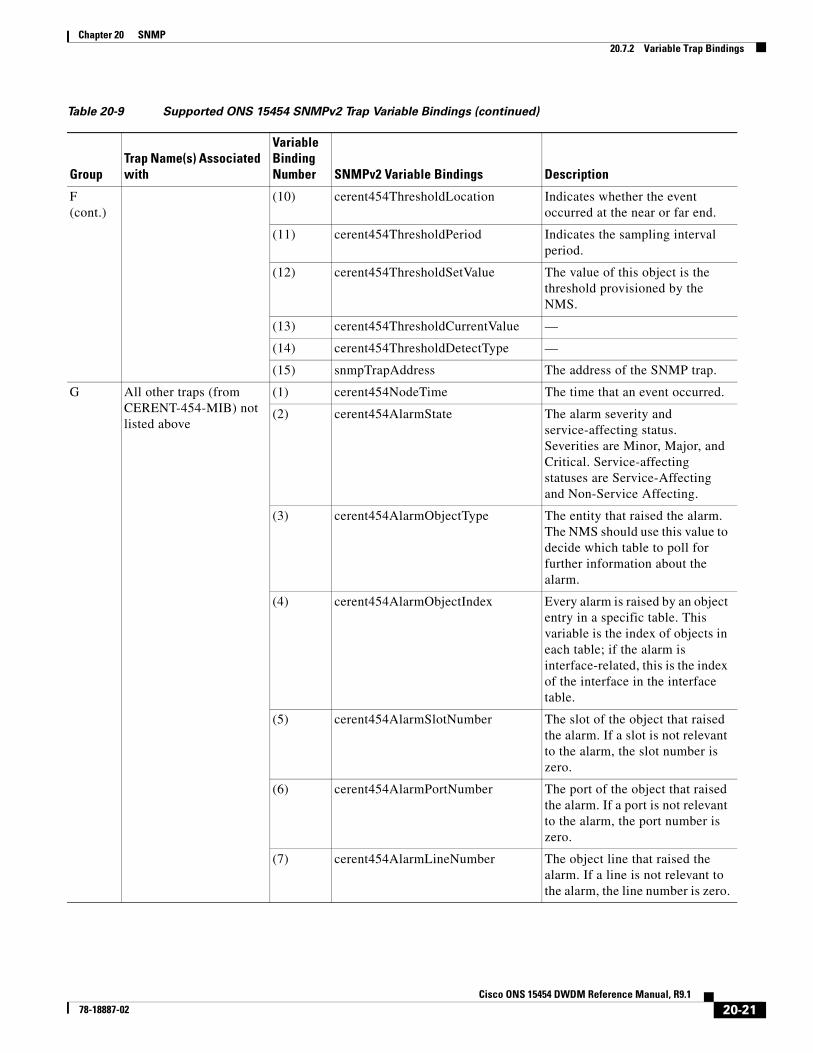
20.7.2 Variable Trap BindingsEach SNMP trap contains variable bindings that are used to create the MIB tables. ONS 15454 traps and variable bindings are listed in Table 20-9. For each group (such as Group A), all traps within the group are associated with all of its variable bindings.
topologyChange RFC1493/BRIDGE-MIB
A port in a bridge has changed from Learning to Forwarding or Forwarding to Blocking.
entConfigChange RFC2737/ENTITY-MIB
The entLastChangeTime value has changed.
dsx1LineStatusChange RFC2495/DS1-MIB
The value of an instance of dsx1LineStatus has changed. The trap can be used by an NMS to trigger polls. When the line status change results from a higher-level line status change (for example, a DS-3), no traps for the DS-1 are sent.
dsx3LineStatusChange RFC2496/DS3-MIB
The value of an instance of dsx3LineStatus has changed. This trap can be used by an NMS to trigger polls. When the line status change results in a lower-level line status change (for example, a DS-1), no traps for the lower-level are sent.
risingAlarm RFC2819/RMON-MIB
The SNMP trap that is generated when an alarm entry crosses the rising threshold and the entry generates an event that is configured for sending SNMP traps.
fallingAlarm RFC2819/RMON-MIB
The SNMP trap that is generated when an alarm entry crosses the falling threshold and the entry generates an event that is configured for sending SNMP traps.
Table 20-8 Supported Generic IETF Traps (continued)
TrapFrom RFC No. MIB Description
20-15Cisco ONS 15454 DWDM Reference Manual, R9.1
78-18887-02

Chapter 20 SNMP20.7.2 Variable Trap Bindings
Table 20-9 Supported ONS 15454 SNMPv2 Trap Variable Bindings
GroupTrap Name(s) Associated with
Variable Binding Number SNMPv2 Variable Bindings Description
A dsx1LineStatusChange (from RFC 2495)
(1) dsx1LineStatus This variable indicates the line status of the interface. It contains loopback, failure, received alarm and transmitted alarm information.
(2) dsx1LineStatusLastChange The value of MIB II’s sysUpTime object at the time this DS1 entered its current line status state. If the current state was entered prior to the last proxy-agent reinitialization, the value of this object is zero.
(3) cerent454NodeTime The time that an event occurred.
(4) cerent454AlarmState The alarm severity and service-affecting status. Severities are Minor, Major, and Critical. Service-affecting statuses are Service-Affecting and Non-Service Affecting.
(5) snmpTrapAddress The address of the SNMP trap.
B dsx3LineStatusChange (from RFC 2496)
(1) dsx3LineStatus This variable indicates the line status of the interface. It contains loopback state information and failure state information.
(2) dsx3LineStatusLastChange The value of MIB II's sysUpTime object at the time this DS3/E3 entered its current line status state. If the current state was entered prior to the last reinitialization of the proxy-agent, then the value is zero.
(3) cerent454NodeTime The time that an event occurred.
B (cont.)
(4) cerent454AlarmState The alarm severity and service-affecting status. Severities are Minor, Major, and Critical. Service-affecting statuses are Service-Affecting and Non-Service Affecting.
(5) snmpTrapAddress The address of the SNMP trap.
20-16Cisco ONS 15454 DWDM Reference Manual, R9.1
78-18887-02

Chapter 20 SNMP20.7.2 Variable Trap Bindings
C coldStart (from RFC 1907)
(1) cerent454NodeTime The time that the event occurred.
warmStart (from RFC 1907)
(2) cerent454AlarmState The alarm severity and service-affecting status. Severities are Minor, Major, and Critical. Service-affecting statuses are Service-Affecting and Non-Service Affecting.
newRoot (from RFC) (3) snmpTrapAddress The address of the SNMP trap.
topologyChange (from RFC)
— —
entConfigChange (from RFC 2737)
— —
authenticationFailure (from RFC 1907)
— —
D1 risingAlarm (from RFC 2819)
(1) alarmIndex This variable uniquely identifies each entry in the alarm table. When an alarm in the table clears, the alarm indexes change for each alarm listed.
(2) alarmVariable The object identifier of the variable being sampled.
(3) alarmSampleType The method of sampling the selected variable and calculating the value to be compared against the thresholds.
(4) alarmValue The value of the statistic during the last sampling period.
Table 20-9 Supported ONS 15454 SNMPv2 Trap Variable Bindings (continued)
GroupTrap Name(s) Associated with
Variable Binding Number SNMPv2 Variable Bindings Description
20-17Cisco ONS 15454 DWDM Reference Manual, R9.1
78-18887-02

Chapter 20 SNMP20.7.2 Variable Trap Bindings
D1 (cont.)
(5) alarmRisingThreshold When the current sampled value is greater than or equal to this threshold, and the value at the last sampling interval was less than this threshold, a single event is generated. A single event is also generated if the first sample after this entry is greater than or equal to this threshold.
(6) cerent454NodeTime The time that an event occurred.
(7) cerent454AlarmState The alarm severity and service-affecting status. Severities are Minor, Major, and Critical. Service-affecting statuses are Service-Affecting and Non-Service Affecting.
(8) snmpTrapAddress The address of the SNMP trap.
D2 fallingAlarm (from RFC 2819)
(1) alarmIndex This variable uniquely identifies each entry in the alarm table. When an alarm in the table clears, the alarm indexes change for each alarm listed.
(2) alarmVariable The object identifier of the variable being sampled.
(3) alarmSampleType The method of sampling the selected variable and calculating the value to be compared against the thresholds.
(4) alarmValue The value of the statistic during the last sampling period.
(5) alarmFallingThreshold When the current sampled value is less than or equal to this threshold, and the value at the last sampling interval was greater than this threshold, a single event is generated. A single is also generated if the first sample after this entry is less than or equal to this threshold.
(6) cerent454NodeTime The time that an event occurred.
Table 20-9 Supported ONS 15454 SNMPv2 Trap Variable Bindings (continued)
GroupTrap Name(s) Associated with
Variable Binding Number SNMPv2 Variable Bindings Description
20-18Cisco ONS 15454 DWDM Reference Manual, R9.1
78-18887-02

Chapter 20 SNMP20.7.2 Variable Trap Bindings
D2 (cont.)
(7) cerent454AlarmState The alarm severity and service-affecting status. Severities are Minor, Major, and Critical. Service-affecting statuses are Service-Affecting and Non-Service Affecting.
(8) snmpTrapAddress The address of the SNMP trap.
E failureDetectedExternalToTheNE (from CERENT-454-mib)
(1) cerent454NodeTime The time that an event occurred.
(2) cerent454AlarmState The alarm severity and service-affecting status. Severities are Minor, Major, and Critical. Service-affecting statuses are Service-Affecting and Non-Service Affecting.
(3) cerent454AlarmObjectType The entity that raised the alarm. The NMS should use this value to decide which table to poll for further information about the alarm.
(4) cerent454AlarmObjectIndex Every alarm is raised by an object entry in a specific table. This variable is the index of objects in each table; if the alarm is interface-related, this is the index of the interface in the interface table.
(5) cerent454AlarmSlotNumber The slot of the object that raised the alarm. If a slot is not relevant to the alarm, the slot number is zero.
(6) cerent454AlarmPortNumber The port of the object that raised the alarm. If a port is not relevant to the alarm, the port number is zero.
(7) cerent454AlarmLineNumber The object line that raised the alarm. If a line is not relevant to the alarm, the line number is zero.
(8) cerent454AlarmObjectName The TL1-style user-visible name that uniquely identifies an object in the system.
Table 20-9 Supported ONS 15454 SNMPv2 Trap Variable Bindings (continued)
GroupTrap Name(s) Associated with
Variable Binding Number SNMPv2 Variable Bindings Description
20-19Cisco ONS 15454 DWDM Reference Manual, R9.1
78-18887-02

Chapter 20 SNMP20.7.2 Variable Trap Bindings
E (cont.)
(9) cerent454AlarmAdditionalInfo Additional information for the alarm object. In the current version of the MIB, this object contains provisioned description for alarms that are external to the NE. If there is no additional information, the value is zero.
(10) snmpTrapAddress The address of the SNMP trap.
F performanceMonitorThresholdCrossingAlert (from CERENT-454-mib)
(1) cerent454NodeTime The time that an event occurred.
(2) cerent454AlarmState The alarm severity and service-affecting status. Severities are Minor, Major, and Critical. Service-affecting statuses are Service-Affecting and Non-Service Affecting.
(3) cerent454AlarmObjectType The entity that raised the alarm. The NMS should use this value to decide which table to poll for further information about the alarm.
(4) cerent454AlarmObjectIndex Every alarm is raised by an object entry in a specific table. This variable is the index of objects in each table; if the alarm is interface-related, this is the index of the interface in the interface table.
(5) cerent454AlarmSlotNumber The slot of the object that raised the alarm. If a slot is not relevant to the alarm, the slot number is zero.
(6) cerent454AlarmPortNumber The port of the object that raised the alarm. If a port is not relevant to the alarm, the port number is zero.
(7) cerent454AlarmLineNumber The object line that raised the alarm. If a line is not relevant to the alarm, the line number is zero.
(8) cerent454AlarmObjectName The TL1-style user-visible name that uniquely identifies an object in the system.
(9) cerent454ThresholdMonitorType This object indicates the type of metric being monitored.
Table 20-9 Supported ONS 15454 SNMPv2 Trap Variable Bindings (continued)
GroupTrap Name(s) Associated with
Variable Binding Number SNMPv2 Variable Bindings Description
20-20Cisco ONS 15454 DWDM Reference Manual, R9.1
78-18887-02
Chapter 20 SNMP20.7.2 Variable Trap Bindings
F (cont.)
(10) cerent454ThresholdLocation Indicates whether the event occurred at the near or far end.
(11) cerent454ThresholdPeriod Indicates the sampling interval period.
(12) cerent454ThresholdSetValue The value of this object is the threshold provisioned by the NMS.
(13) cerent454ThresholdCurrentValue —
(14) cerent454ThresholdDetectType —
(15) snmpTrapAddress The address of the SNMP trap.
G All other traps (from CERENT-454-MIB) not listed above
(1) cerent454NodeTime The time that an event occurred.
(2) cerent454AlarmState The alarm severity and service-affecting status. Severities are Minor, Major, and Critical. Service-affecting statuses are Service-Affecting and Non-Service Affecting.
(3) cerent454AlarmObjectType The entity that raised the alarm. The NMS should use this value to decide which table to poll for further information about the alarm.
(4) cerent454AlarmObjectIndex Every alarm is raised by an object entry in a specific table. This variable is the index of objects in each table; if the alarm is interface-related, this is the index of the interface in the interface table.
(5) cerent454AlarmSlotNumber The slot of the object that raised the alarm. If a slot is not relevant to the alarm, the slot number is zero.
(6) cerent454AlarmPortNumber The port of the object that raised the alarm. If a port is not relevant to the alarm, the port number is zero.
(7) cerent454AlarmLineNumber The object line that raised the alarm. If a line is not relevant to the alarm, the line number is zero.
Table 20-9 Supported ONS 15454 SNMPv2 Trap Variable Bindings (continued)
GroupTrap Name(s) Associated with
Variable Binding Number SNMPv2 Variable Bindings Description
20-21Cisco ONS 15454 DWDM Reference Manual, R9.1
78-18887-02

Chapter 20 SNMP20.8 SNMPv1/v2 Community Names
20.8 SNMPv1/v2 Community NamesCommunity names are used to group SNMP trap destinations. All ONS 15454 trap destinations can be provisioned as part of SNMP communities in CTC. When community names are assigned to traps, the ONS 15454 treats the request as valid if the community name matches one that is provisioned in CTC. In this case, all agent-managed MIB variables are accessible to that request. If the community name does not match the provisioned list, SNMP drops the request.
20.9 SNMP in Multishelf ManagementWhen using the dense wavelength division multiplexing (DWDM) multishelf management feature to subtend shelves from a node controller shelf, SNMP for the subtended shelves must be specially provisioned. All shelves within a multishelf configuration share the node controller’s ID and IP address. Thus, the only way to route SNMP messages to or from subtended shelves is by using proxy ARP.
The cerent454MultishelfEnabled object ID (OID) can be used to determine whether the node is single shelf or multishelf.
To view the OID, use the snmpwalk node IP address ifDescr SNMP command in global configuration mode. This command output displays the OID as
<interface_name>_x/y/z
where
x = Shelf number (for a multishelf node)
y = Card slot number
z = Card port number.
The following example shows how to obtain the OID using the snmpwalk node IP address ifDescr SNMP command.
Router(config)# snmpwalk 192.0.2.1 ifDescrRFC1213-MIB::ifDescr.1 = STRING: "motfcc0"RFC1213-MIB::ifDescr.6 = STRING: "pdcc0"RFC1213-MIB::ifDescr.7 = STRING: "pdcc1"RFC1213-MIB::ifDescr.8 = STRING: "pdcc2"RFC1213-MIB::ifDescr.9 = STRING: "pdcc3"RFC1213-MIB::ifDescr.10 = STRING: "pdcc4"RFC1213-MIB::ifDescr.11 = STRING: "pdcc5"RFC1213-MIB::ifDescr.12 = STRING: "pdcc6"RFC1213-MIB::ifDescr.13 = STRING: "pdcc7"RFC1213-MIB::ifDescr.14 = STRING: "pdcc8"RFC1213-MIB::ifDescr.15 = STRING: "pdcc9"RFC1213-MIB::ifDescr.16 = STRING: "pdcc10"
G (cont.)
(8) cerent454AlarmObjectName The TL1-style user-visible name that uniquely identifies an object in the system.
(9) snmpTrapAddress The address of the SNMP trap.
Table 20-9 Supported ONS 15454 SNMPv2 Trap Variable Bindings (continued)
GroupTrap Name(s) Associated with
Variable Binding Number SNMPv2 Variable Bindings Description
20-22Cisco ONS 15454 DWDM Reference Manual, R9.1
78-18887-02

Chapter 20 SNMP20.9 SNMP in Multishelf Management
RFC1213-MIB::ifDescr.17 = STRING: "pdcc11"RFC1213-MIB::ifDescr.18 = STRING: "pdcc12"RFC1213-MIB::ifDescr.19 = STRING: "pdcc13"RFC1213-MIB::ifDescr.20 = STRING: "pdcc14"RFC1213-MIB::ifDescr.21 = STRING: "pdcc15"RFC1213-MIB::ifDescr.22 = STRING: "pdcc16"RFC1213-MIB::ifDescr.23 = STRING: "pdcc17"RFC1213-MIB::ifDescr.24 = STRING: "pdcc18"RFC1213-MIB::ifDescr.25 = STRING: "pdcc19"RFC1213-MIB::ifDescr.26 = STRING: "pdcc20"RFC1213-MIB::ifDescr.27 = STRING: "pdcc21"RFC1213-MIB::ifDescr.28 = STRING: "pdcc22"RFC1213-MIB::ifDescr.29 = STRING: "pdcc23"RFC1213-MIB::ifDescr.30 = STRING: "pdcc24"RFC1213-MIB::ifDescr.31 = STRING: "pdcc25"RFC1213-MIB::ifDescr.32 = STRING: "pdcc26"RFC1213-MIB::ifDescr.33 = STRING: "pdcc27"RFC1213-MIB::ifDescr.34 = STRING: "pdcc28"RFC1213-MIB::ifDescr.35 = STRING: "pdcc29"RFC1213-MIB::ifDescr.36 = STRING: "pdcc30"RFC1213-MIB::ifDescr.37 = STRING: "pdcc31"RFC1213-MIB::ifDescr.38 = STRING: "pdcc32"RFC1213-MIB::ifDescr.39 = STRING: "pdcc33"RFC1213-MIB::ifDescr.40 = STRING: "pdcc34"RFC1213-MIB::ifDescr.41 = STRING: "pdcc35"RFC1213-MIB::ifDescr.42 = STRING: "pdcc36"RFC1213-MIB::ifDescr.43 = STRING: "pdcc37"RFC1213-MIB::ifDescr.44 = STRING: "pdcc38"RFC1213-MIB::ifDescr.45 = STRING: "pdcc39"RFC1213-MIB::ifDescr.46 = STRING: "pdcc40"RFC1213-MIB::ifDescr.47 = STRING: "pdcc41"RFC1213-MIB::ifDescr.48 = STRING: "pdcc42"RFC1213-MIB::ifDescr.49 = STRING: "pdcc43"RFC1213-MIB::ifDescr.50 = STRING: "pdcc44"RFC1213-MIB::ifDescr.51 = STRING: "pdcc45"RFC1213-MIB::ifDescr.52 = STRING: "pdcc46"RFC1213-MIB::ifDescr.53 = STRING: "pdcc47"RFC1213-MIB::ifDescr.54 = STRING: "pdcc48"RFC1213-MIB::ifDescr.55 = STRING: "pdcc49"RFC1213-MIB::ifDescr.56 = STRING: "pdcc50"RFC1213-MIB::ifDescr.57 = STRING: "pdcc51"RFC1213-MIB::ifDescr.58 = STRING: "pdcc52"RFC1213-MIB::ifDescr.59 = STRING: "pdcc53"RFC1213-MIB::ifDescr.60 = STRING: "pdcc54"RFC1213-MIB::ifDescr.61 = STRING: "pdcc55"RFC1213-MIB::ifDescr.62 = STRING: "pdcc56"RFC1213-MIB::ifDescr.63 = STRING: "pdcc57"RFC1213-MIB::ifDescr.64 = STRING: "pdcc58"RFC1213-MIB::ifDescr.65 = STRING: "pdcc59"RFC1213-MIB::ifDescr.66 = STRING: "pdcc60"RFC1213-MIB::ifDescr.67 = STRING: "pdcc61"RFC1213-MIB::ifDescr.68 = STRING: "pdcc62"RFC1213-MIB::ifDescr.69 = STRING: "pdcc63"RFC1213-MIB::ifDescr.70 = STRING: "pdcc64"RFC1213-MIB::ifDescr.71 = STRING: "pdcc65"RFC1213-MIB::ifDescr.72 = STRING: "pdcc66"RFC1213-MIB::ifDescr.73 = STRING: "pdcc67"RFC1213-MIB::ifDescr.74 = STRING: "pdcc68"RFC1213-MIB::ifDescr.75 = STRING: "pdcc69"RFC1213-MIB::ifDescr.76 = STRING: "pdcc70"RFC1213-MIB::ifDescr.77 = STRING: "pdcc71"RFC1213-MIB::ifDescr.78 = STRING: "pdcc72"RFC1213-MIB::ifDescr.79 = STRING: "pdcc73"RFC1213-MIB::ifDescr.80 = STRING: "pdcc74"
20-23Cisco ONS 15454 DWDM Reference Manual, R9.1
78-18887-02
Chapter 20 SNMP20.10 SNMPv1/v2 Proxy Over Firewalls
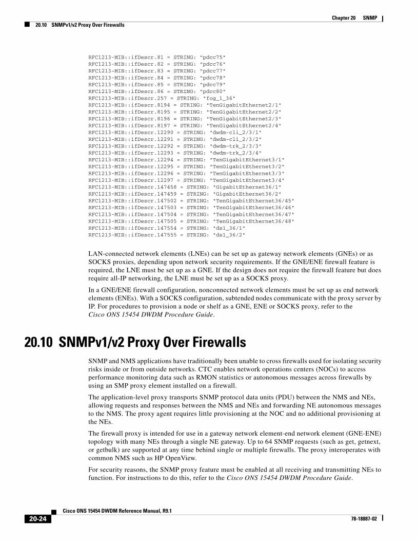
RFC1213-MIB::ifDescr.81 = STRING: "pdcc75"RFC1213-MIB::ifDescr.82 = STRING: "pdcc76"RFC1213-MIB::ifDescr.83 = STRING: "pdcc77"RFC1213-MIB::ifDescr.84 = STRING: "pdcc78"RFC1213-MIB::ifDescr.85 = STRING: "pdcc79"RFC1213-MIB::ifDescr.86 = STRING: "pdcc80"RFC1213-MIB::ifDescr.257 = STRING: "fog_1_36"RFC1213-MIB::ifDescr.8194 = STRING: "TenGigabitEthernet2/1"RFC1213-MIB::ifDescr.8195 = STRING: "TenGigabitEthernet2/2"RFC1213-MIB::ifDescr.8196 = STRING: "TenGigabitEthernet2/3"RFC1213-MIB::ifDescr.8197 = STRING: "TenGigabitEthernet2/4"RFC1213-MIB::ifDescr.12290 = STRING: "dwdm-cli_2/3/1"RFC1213-MIB::ifDescr.12291 = STRING: "dwdm-cli_2/3/2"RFC1213-MIB::ifDescr.12292 = STRING: "dwdm-trk_2/3/3"RFC1213-MIB::ifDescr.12293 = STRING: "dwdm-trk_2/3/4"RFC1213-MIB::ifDescr.12294 = STRING: "TenGigabitEthernet3/1"RFC1213-MIB::ifDescr.12295 = STRING: "TenGigabitEthernet3/2"RFC1213-MIB::ifDescr.12296 = STRING: "TenGigabitEthernet3/3"RFC1213-MIB::ifDescr.12297 = STRING: "TenGigabitEthernet3/4"RFC1213-MIB::ifDescr.147458 = STRING: "GigabitEthernet36/1"RFC1213-MIB::ifDescr.147459 = STRING: "GigabitEthernet36/2"RFC1213-MIB::ifDescr.147502 = STRING: "TenGigabitEthernet36/45"RFC1213-MIB::ifDescr.147503 = STRING: "TenGigabitEthernet36/46"RFC1213-MIB::ifDescr.147504 = STRING: "TenGigabitEthernet36/47"RFC1213-MIB::ifDescr.147505 = STRING: "TenGigabitEthernet36/48"RFC1213-MIB::ifDescr.147554 = STRING: "ds1_36/1"RFC1213-MIB::ifDescr.147555 = STRING: "ds1_36/2"
LAN-connected network elements (LNEs) can be set up as gateway network elements (GNEs) or as SOCKS proxies, depending upon network security requirements. If the GNE/ENE firewall feature is required, the LNE must be set up as a GNE. If the design does not require the firewall feature but does require all-IP networking, the LNE must be set up as a SOCKS proxy.
In a GNE/ENE firewall configuration, nonconnected network elements must be set up as end network elements (ENEs). With a SOCKS configuration, subtended nodes communicate with the proxy server by IP. For procedures to provision a node or shelf as a GNE, ENE or SOCKS proxy, refer to the Cisco ONS 15454 DWDM Procedure Guide.
20.10 SNMPv1/v2 Proxy Over FirewallsSNMP and NMS applications have traditionally been unable to cross firewalls used for isolating security risks inside or from outside networks. CTC enables network operations centers (NOCs) to access performance monitoring data such as RMON statistics or autonomous messages across firewalls by using an SMP proxy element installed on a firewall.
The application-level proxy transports SNMP protocol data units (PDU) between the NMS and NEs, allowing requests and responses between the NMS and NEs and forwarding NE autonomous messages to the NMS. The proxy agent requires little provisioning at the NOC and no additional provisioning at the NEs.
The firewall proxy is intended for use in a gateway network element-end network element (GNE-ENE) topology with many NEs through a single NE gateway. Up to 64 SNMP requests (such as get, getnext, or getbulk) are supported at any time behind single or multiple firewalls. The proxy interoperates with common NMS such as HP OpenView.
For security reasons, the SNMP proxy feature must be enabled at all receiving and transmitting NEs to function. For instructions to do this, refer to the Cisco ONS 15454 DWDM Procedure Guide.
20-24Cisco ONS 15454 DWDM Reference Manual, R9.1
78-18887-02

Chapter 20 SNMP20.11 SNMPv3 Proxy Configuration
20.11 SNMPv3 Proxy ConfigurationThe GNE can act as a proxy for the ENEs and forward SNMP requests to other SNMP entities (ENEs) irrespective of the types of objects that are accessed. For this, you need to configure two sets of users, one between the GNE and NMS, and the other between the GNE and ENE. In addition to forwarding requests from the NMS to the ENE, the GNE also forwards responses and traps from the ENE to the NMS.
The proxy forwarder application is defined in RFC 3413. Each entry in the Proxy Forwarder Table consists of the following parameters:
• Proxy Type—Defines the type of message that may be forwarded based on the translation parameters defined by this entry. If the Proxy Type is read or write, the proxy entry is used for forwarding SNMP requests and their response between the NMS and the ENE. If the Proxy Type is trap, the entry is used for forwarding SNMP traps from the ENE to the NMS.
• Context Engine ID/Context Name—Specifies the ENE to which the incoming requests should be forwarded or the ENE whose traps should be forwarded to the NMS by the GNE.
• TargetParamsIn—Points to the Target Params Table that specifies the GNE user who proxies on behalf of an ENE user. When the proxy type is read or write, TargetParamsIn specifies the GNE user who receives requests from an NMS, and forwards requests to the ENE. When the proxy type is trap, TargetParamsIn specifies the GNE user who receives notifications from the ENE and forwards them to the NMS. TargetParamsIn and the contextEngineID or the contextName columns are used to determine the row in the Proxy Forwarder Table that could be used for forwarding the received message.
• Single Target Out—Refers to the Target Address Table. After you select a row in the Proxy Forwarder Table for forwarding, this object is used to get the target address and the target parameters that are used for forwarding the request. This object is used for requests with proxy types read or write, which only requires one target.
• Multiple Target Out (Tag)—Refers to a group of entries in the Target Address Table. Notifications are forwarded using this tag. The Multiple Target Out tag is only relevant when proxy type is Trap and is used to send notifications to one or more NMSs.
20.12 Remote MonitoringThe ONS 15454 incorporates RMON to allow network operators to monitor Ethernet card performance and events. The RMON thresholds are user-provisionable in CTC. Refer to the Cisco ONS 15454 DWDM Procedure Guide for instructions.
Note Typical RMON operations, other than threshold provisioning, are invisible to the CTC user.
ONS 15454 system RMON is based on the IETF-standard MIB RFC 2819 and includes the following five groups from the standard MIB: Ethernet Statistics, History Control, Ethernet History, Alarm, and Event.
20-25Cisco ONS 15454 DWDM Reference Manual, R9.1
78-18887-02

Chapter 20 SNMP20.12.1 64-Bit RMON Monitoring over DCC
20.12.1 64-Bit RMON Monitoring over DCCThe ONS 15454 DCC is implemented over the IP protocol, which is not compatible with Ethernet. The system builds Ethernet equipment History and Statistics tables using HDLC statistics that are gathered over the DCC (running point-topoint protocol, or PPP). RMON DCC monitoring (for both IP and Ethernet) monitors the health of remote DCC connections.
RMON DCC contains two MIBs for DCC interfaces. They are:
• cMediaIndependentTable—standard, rfc3273; the proprietary extension of the HC-RMON MIB used for reporting statistics
• cMediaIndependentHistoryTable—proprietary MIB used to support history
20.12.1.1 Row Creation in MediaIndependentTable
The SetRequest PDU for creating a row in the mediaIndependentTable should contain all the values required to activate a row in a single set operation along with an assignment of the status variable to createRequest (2). The SetRequest PDU for entry creation must have all the object IDs (OIDs) carrying an instance value of 0. That is, all the OIDs should be of the type OID.0.
In order to create a row, the SetRequest PDU should contain the following:
• mediaIndependentDataSource and its desired value
• mediaIndependentOwner and its desired value (The size of mediaIndependentOwner is limited to 32 characters.)
• mediaIndependentStatus with a value of createRequest (2)
The mediaIndependentTable creates a row if the SetRequest PDU is valid according to the above rules. When the row is created, the SNMP agent decides the value of mediaIndependentIndex. This value is not sequentially allotted or contiguously numbered. It changes when an Ethernet interface is added or deleted. The newly created row will have mediaIndependentTable value of valid (1). If the row already exists, or if the SetRequest PDU values are insufficient or do not make sense, the SNMP agent returns an error code.
Note mediaIndependentTable entries are not preserved if the SNMP agent is restarted.
The mediaIndependentTable deletes a row if the SetRequest PDU contains a mediaIndependentStatus with a value of invalid (4). The varbind’s OID instance value identifies the row for deletion. You can recreate a deleted row in the table if desired.
20.12.1.2 Row Creation in cMediaIndependentHistoryControlTable
SNMP row creation and deletion for the cMediaIndependentHistoryControlTable follows the same processes as for the MediaIndependentTable; only the variables differ.
In order to create a row, the SetRequest PDU should contain the following:
• cMediaIndependentHistoryControlDataSource and its desired value
• cMediaIndependentHistoryControlOwner and its desired value
• cMediaIndependentHistoryControlStatus with a value of createRequest (2)
20-26Cisco ONS 15454 DWDM Reference Manual, R9.1
78-18887-02

Chapter 20 SNMP20.12.2 HC-RMON-MIB Support
20.12.2 HC-RMON-MIB SupportFor the ONS 15454, the implementation of the high-capacity remote monitoring information base (HC-RMON-MIB, or RFC 3273) enables 64-bit support of existing RMON tables. This support is provided with the etherStatsHighCapacityTable and the etherHistoryHighCapacityTable. An additional table, the mediaIndependentTable, and an additional object, hcRMONCapabilities, are also added for this support. All of these elements are accessible by any third-party SNMP client should have the ability to upload RFC 3273 SNMP MIB variables in the etherStatsHighCapacityTable, etherHistoryHighCapacityTable, or mediaIndependentTable.
20.12.3 Ethernet Statistics RMON GroupThe Ethernet Statistics group contains the basic statistics monitored for each subnetwork in a single table called the etherStatsTable.
20.12.3.1 Row Creation in etherStatsTable
The SetRequest PDU for creating a row in this table should contain all the values needed to activate a row in a single set operation, and an assigned status variable to createRequest. The SetRequest PDU object ID (OID) entries must all carry an instance value, or type OID, of 0.
In order to create a row, the SetRequest PDU should contain the following:
• The etherStatsDataSource and its desired value
• The etherStatsOwner and its desired value (size of this value is limited to 32 characters)
• The etherStatsStatus with a value of createRequest (2)
The etherStatsTable creates a row if the SetRequest PDU is valid according to the above rules. When the row is created, the SNMP agent decides the value of etherStatsIndex. This value is not sequentially allotted or contiguously numbered. It changes when an Ethernet interface is added or deleted. The newly created row will have etherStatsStatus value of valid (1).
If the etherStatsTable row already exists, or if the SetRequest PDU values are insufficient or do not make sense, the SNMP agent returns an error code.
Note EtherStatsTable entries are not preserved if the SNMP agent is restarted.
20.12.3.2 Get Requests and GetNext Requests
Get requests and getNext requests for the etherStatsMulticastPkts and etherStatsBroadcastPkts columns return a value of zero because the variables are not supported by ONS 15454 Ethernet cards.
20.12.3.3 Row Deletion in etherStatsTable
To delete a row in the etherStatsTable, the SetRequest PDU should contain an etherStatsStatus “invalid” value (4). The OID marks the row for deletion. If required, a deleted row can be recreated.
20-27Cisco ONS 15454 DWDM Reference Manual, R9.1
78-18887-02

Chapter 20 SNMP20.12.4 History Control RMON Group
20.12.3.4 64-Bit etherStatsHighCapacity Table
The Ethernet statistics group contains 64-bit statistics in the etherStatsHighCapacityTable, which provides 64-bit RMON support for the HC-RMON-MIB. The etherStatsHighCapacityTable is an extension of the etherStatsTable that adds 16 new columns for performance monitoring data in 64-bit format. There is a one-to-one relationship between the etherStatsTable and etherStatsHighCapacityTable when rows are created or deleted in either table.
20.12.4 History Control RMON GroupThe History Control group defines sampling functions for one or more monitor interfaces in the historyControlTable. The values in this table, as specified in RFC 2819, are derived from the historyControlTable and etherHistoryTable.
20.12.4.1 History Control Table
The RMON is sampled at one of four possible intervals. Each interval or period contains specific history values (also called buckets). Table 20-10 lists the four sampling periods and corresponding buckets.
The historyControlTable maximum row size is determined by multiplying the number of ports on a card by the number of sampling periods. For example, a card that contains 24 ports when multiplied by periods allows 96 rows in the table. A card that contains 14 ports when multiplied by four periods allows 56 table rows.
20.12.4.2 Row Creation in historyControlTable
The SetRequest PDU must be able to activate a historyControlTable row in one single-set operation. In order to do this, the PDU must contain all needed values and have a status variable value of 2 (createRequest). All OIDs in the SetRequest PDU should be type OID.0 type for entry creation.
To create a SetRequest PDU for the historyControlTable, the following values are required:
• The historyControlDataSource and its desired value
• The historyControlBucketsRequested and it desired value
• The historyControlInterval and its desired value
• The historyControlOwner and its desired value
• The historyControlStatus with a value of createRequest (2)
The historyControlBucketsRequested OID value is ignored because the number of buckets allowed for each sampling period, based upon the historyControlInterval value, is already fixed. Table 20-10 lists these variables.
Table 20-10 RMON History Control Periods and History Categories
Sampling Periods(historyControlValue Variable)
Total Values or Buckets(historyControl Variable)
15 minutes 32
24 hours 7
1 minute 60
60 minutes 24
20-28Cisco ONS 15454 DWDM Reference Manual, R9.1
78-18887-02

Chapter 20 SNMP20.12.5 Ethernet History RMON Group
The historyControlInterval value cannot be changed from the four allowed choices. If you use another value, the SNMP agent selects the closest smaller time period from the set buckets. For example, if the set request specifies a 25-minute interval, this falls between the 15-minute (32 bucket) variable and the 60-minute (24 bucket) variable. The SNMP agent automatically selects the lower, closer value, which is 15 minutes, so it allows 32 buckets.
If the SetRequest PDU is valid, a historyControlTable row is created. If the row already exists, or if the SetRequest PDU values do not make sense or are insufficient, the SNMP agent does not create the row and returns an error code.
20.12.4.3 Get Requests and GetNext Requests
These PDUs are not restricted.
20.12.4.4 Row Deletion in historyControl Table
To delete a row from the table, the SetRequest PDU should contain a historyControlStatus value of 4 (invalid). A deleted row can be recreated.
20.12.5 Ethernet History RMON GroupThe ONS 15454 implements the etherHistoryTable as defined in RFC 2819. The group is created within the bounds of the historyControlTable and does not deviate from the RFC in its design.
20.12.5.1 64-Bit etherHistoryHighCapacityTable
64-bit Ethernet history for the HC-RMON-MIB is implemented in the etherHistoryHighCapacityTable, which is an extension of the etherHistoryTable. The etherHistoryHighCapacityTable adds four columns for 64-bit performance monitoring data. These two tables have a one-to-one relationship. Adding or deleting a row in one table will also change the other.
20.12.6 Alarm RMON GroupThe Alarm group consists of the alarmTable, which periodically compares sampled values with configured thresholds and raises an event if a threshold is crossed. This group requires the implementation of the event group, which follows this section.
20.12.6.1 Alarm Table
The NMS uses the alarmTable to determine and provision network performance alarmable thresholds.
20.12.6.2 Row Creation in alarmTable
To create a row in the alarmTable, the SetRequest PDU must be able to create the row in one single-set operation. All OIDs in the SetRequest PDU should be type OID.0 type for entry creation. The table has a maximum number of 256 rows.
To create a SetRequest PDU for the alarmTable, the following values are required:
20-29Cisco ONS 15454 DWDM Reference Manual, R9.1
78-18887-02

Chapter 20 SNMP20.12.6 Alarm RMON Group
• The alarmInterval and its desired value
• The alarmVariable and its desired value
• The alarmSampleType and its desired value
• The alarmStartupAlarm and its desired value
• The alarmOwner and its desired value
• The alarmStatus with a value of createRequest (2)
If the SetRequest PDU is valid, a historyControlTable row is created. If the row already exists, or if the SetRequest PDU values do not make sense or are insufficient, the SNMP agent does not create the row and returns an error code.
In addition to the required values, the following restrictions must be met in the SetRequest PDU:
• The alarmOwner is a string of length 32 characters.
• The alarmRisingEventIndex always takes value 1.
• The alarmFallingEventIndex always takes value 2.
• The alarmStatus has only two values supported in SETs: createRequest (2) and invalid (4).
• The AlarmVariable is of the type OID.ifIndex, where ifIndex gives the interface this alarm is created on and OID is one of the OIDs supported in Table 20-11.
Table 20-11 OIDs Supported in the AlarmTable
No. Column Name OID Status
1 ifInOctets {1.3.6.1.2.1.2.2.1.10} —
2 IfInUcastPkts {1.3.6.1.2.1.2.2.1.11} —
3 ifInMulticastPkts {1.3.6.1.2.1.31.1.1.1.2} Unsupported in E100/E1000
4 ifInBroadcastPkts {1.3.6.1.2.1.31.1.1.1.3} Unsupported in E100/E1000
5 ifInDiscards {1.3.6.1.2.1.2.2.1.13} Unsupported in E100/E1000
6 ifInErrors {1.3.6.1.2.1.2.2.1.14} —
7 ifOutOctets {1.3.6.1.2.1.2.2.1.16} —
8 ifOutUcastPkts {1.3.6.1.2.1.2.2.1.17} —
9 ifOutMulticastPkts {1.3.6.1.2.1.31.1.1.1.4} Unsupported in E100/E1000
10 ifOutBroadcastPkts {1.3.6.1.2.1.31.1.1.1.5} Unsupported in E100/E1000
11 ifOutDiscards {1.3.6.1.2.1.2.2.1.19} Unsupported in E100/E1000
12 Dot3StatsAlignmentErrors {1.3.6.1.2.1.10.7.2.1.2} —
13 Dot3StatsFCSErrors {1.3.6.1.2.1.10.7.2.1.3} —
14 Dot3StatsSingleCollisionFrames {1.3.6.1.2.1.10.7.2.1.4} —
15 Dot3StatsMultipleCollisionFrames {1.3.6.1.2.1.10.7.2.1.5} —
16 Dot3StatsDeferredTransmissions {1.3.6.1.2.1.10.7.2.1.7} —
17 Dot3StatsLateCollisions {1.3.6.1.2.1.10.7.2.1.8} —
18 Dot3StatsExcessiveCollisions {13.6.1.2.1.10.7.2.1.9} —
19 Dot3StatsFrameTooLong {1.3.6.1.2.1.10.7.2.1.13} —
20 Dot3StatsCarrierSenseErrors {1.3.6.1.2.1.10.7.2.1.11} Unsupported in E100/E1000
20-30Cisco ONS 15454 DWDM Reference Manual, R9.1
78-18887-02

Chapter 20 SNMP20.12.7 Event RMON Group
20.12.6.3 Get Requests and GetNext Requests
These PDUs are not restricted.
20.12.6.4 Row Deletion in alarmTable
To delete a row from the table, the SetRequest PDU should contain an alarmStatus value of 4 (invalid). A deleted row can be recreated. Entries in this table are preserved if the SNMP agent is restarted.
20.12.7 Event RMON Group The Event group controls event generation and notification. It consists of two tables: the eventTable, which is a read-only list of events to be generated, and the logTable, which is a writable set of data describing a logged event. The ONS 15454 implements the logTable as specified in RFC 2819.
20.12.7.1 Event Table
The eventTable is read-only and unprovisionable. The table contains one row for rising alarms and another for falling ones. This table has the following restrictions:
• The eventType is always log-and-trap (4).
21 Dot3StatsSQETestErrors {1.3.6.1.2.1.10.7.2.1.6} Unsupported in E100/E1000
22 etherStatsUndersizePkts {1.3.6.1.2.1.16.1.1.1.9} —
23 etherStatsFragments {1.3.6.1.2.1.16.1.1.1.11} —
24 etherStatsPkts64Octets {1.3.6.1.2.1.16.1.1.1.14} —
25 etherStatsPkts65to127Octets {1.3.6.1.2.1.16.1.1.1.15} —
26 etherStatsPkts128to255Octets {1.3.6.1.2.1.16.1.1.1.16} —
27 etherStatsPkts256to511Octets {1.3.6.1.2.1.16.1.1.1.17} —
28 etherStatsPkts512to1023Octets {1.3.6.1.2.1.16.1.1.1.18} —
29 etherStatsPkts1024to1518Octets {1.3.6.1.2.1.16.1.1.1.19} —
30 EtherStatsBroadcastPkts {1.3.6.1.2.1.16.1.1.1.6} —
31 EtherStatsMulticastPkts {1.3.6.1.2.1.16.1.1.1.7} —
32 EtherStatsOversizePkts {1.3.6.1.2.1.16.1.1.1.10} —
33 EtherStatsJabbers {1.3.6.1.2.1.16.1.1.1.12} —
34 EtherStatsOctets {1.3.6.1.2.1.16.1.1.1.4} —
35 EtherStatsCollisions {1.3.6.1.2.1.16.1.1.1.13} —
36 EtherStatsCollisions {1.3.6.1.2.1.16.1.1.1.8} —
37 EtherStatsDropEvents {1.3.6.1.2.1.16.1.1.1.3} Unsupported in E100/E1000 and G1000
Table 20-11 OIDs Supported in the AlarmTable (continued)
No. Column Name OID Status
20-31Cisco ONS 15454 DWDM Reference Manual, R9.1
78-18887-02

Chapter 20 SNMP20.12.7 Event RMON Group
• The eventCommunity value is always a zero-length string, indicating that this event causes the trap to be despatched to all provisioned destinations.
• The eventOwner column value is always “monitor.”
• The eventStatus column value is always valid(1).
20.12.7.2 Log Table
The logTable is implemented exactly as specified in RFC 2819. The logTable is based upon data that is locally cached in a controller card. If there is a controller card protection switch, the existing logTable is cleared and a new one is started on the newly active controller card. The table contains as many rows as provided by the alarm controller.
20-32Cisco ONS 15454 DWDM Reference Manual, R9.1
78-18887-02