smc - features how to order symbols ac 30 f 03 de...af40 ar40 al40 1/4 3/8 1/2 1/4 af40-06 ar40-06...
TRANSCRIPT

Modular F.R.L. Unit – Series AC 981
Air
Pre
par
atio
n
For more product options and details see our specifi c catalogues or on-line information.
AC 30 F 03 DE
Body size
Model combination
F.R.L. unit
Symbol
–ABCD
Air filter(1)—(1)(1)—
Regulator(2)—(2)(3)—
Lubricator(3)(2)———
Filterregulator
—(1)——(1)
Mistseparator
———(2)(2)
Combination
Thread type–F
Metric system thread (M5) (AC10 only)G
Port size
Options
Note 1) The number inside ( ) indicates the combination order counted from the inlet side.
6055504030252010
Symbol
M5010203040610
Portsize
M51/81/43/81/23/41
10�——————
20—��————
25——��———
30——��———
40——����—
50—————��
55——————�
60——————�
Body size
Air Filter Regulator Lubricator
Filter Regulator Lubricator
Air Filter Regulator
Air Filter Mist Separator Regulator
Filter Regulator Mist Separator
—
A
B
C
D
10 20 25 30 40 50 55 60
Body size
—CD
Without auto drain / Without pressure gaugeFloat type auto drain (N.C.)Float type auto drain (N.O.)
E
G
ME1E2E3E4
Square embedded type pressure gauge (with limit indicator)Round type pressure gauge (without limit indicator)Round type pressure gauge (with limit indicator)Round type pressure gauge (with colour zone)Output: NPN output / Electrical entry: Wiring bottom entry Output: NPN output / Electrical entry: Wiring top entryOutput: PNP output / Electrical entry: Wiring bottom entry Output: PNP output / Electrical entry: Wiring top entry
Modular F.R.L. UnitSeries AC
• Ready assembled air preparation sets.• Choice of filter, regulator and lubricator options.• Sizes from M5 to 1" ports.• Autodrain and gauges can be specified.• Saves procurement and assembly times.
Features
How to Order Symbols
(Accessories)Series VHS - Residual Relief 3 Port Valve - page 1072Series IS10 - Pressure Switches - page 1093Series E210/310/410 - Modular Adapter - page 1074Series AKM - Check Valve - page 1091
(Related Products)Series IDG - Membrane Air Dryer - page 1142Series AV - Soft Start-up Valves - www.smc.euSeries KK - S Couplers - page 1204Series KQ2 - Fittings - page 1184Series TU - Tubing - page 1223
Accessories and Related Products
AC10-M5 *AC20-F01 *AC20-F02 *AC30-F02 *AC30-F03 *AC40-F03 *AC40-F04 *AC40-F06 *AC50-F06 *AC50-F10 *AC60-F10 *
Product Recommendation
Stocked items for fast delivery
–, G–, C, CE, E, G–, C, CE, E, G–, D, DE, E–, CE, D, DE, DG, E, E3, G–, DE–, D, DE, DG, E, G–, D, DE, DG, E, G–, C, D, DE, DG, E–, D, DE, DG, E–, D, DE, DG, E, G
AC10A-M5 *AC20A-F01 *AC20A-F02 *AC30A-F02 *AC30A-F03 *AC40A-F02 *AC40A-F03 *AC40A-F04 *AC40A-F06 *AC50A-F06 *AC60A-F10 *
–, C, G–, C, CE, E, G–, C, CE, CG, E, G–, C, CE, D, DE, E–, C, CE, D, DE, DG, E, G–, D, E, G–, D, DE, E–, C, CG, D, DE, DG, E, G–, D, DE, DG, E, G––, E
AC10B-M5 *AC20B-F01 *AC25B-F02 *AC30B-F03 *AC40B-F04 *AC40B-F06 *AC50B-F06 *AC50B-F10 *AC60B-F10 *AC25C-F02AC30C-F02
––, CE–, C, D, E, G–, D, DG, G–, D, DG, E, GDE, DG, G–, D–, D–, DG, E, GCE–
AC30C-F03 *AC40C-F03 *AC40C-F04 *AC20D-F01 *AC20D-F02 * AC30D-F03 *AC40D-F03 *AC40D-F04 *AC40D-F06 *
DE––, DE––D–, D, DE–
Model Options (*) Model Options (*) Model Options (*) Model Options (*)
* When more than one specification is required, indicate in ascending alphanumeric order
SMC´s FRL units will be progressively renewed.Please check if the model you require is alreadyavailable in the renewed models (pages 1006 to 1011)
Series AC – Modular F.R.L. Unit982
Air
Prep
aration
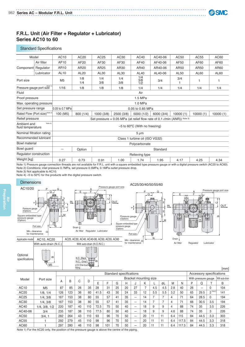
F.R.L. Unit (Air Filter + Regulator + Lubricator)Series AC10 to 60
Air1.5 MPa1.0 MPa
0.05 to 0.85 MPa
Set pressure + 0.05 MPa (at relief flow rate of 0.1 l/min (ANR)) Note 3)
–5 to 60ºC (With no freezing)
5 μmClass 1 turbine oil (ISO VG32)
Polycarbonate
Relieving type
0.05 to 0.7 MPa
Note 1) Pressure gauge connection threads are not available for F.R.L. unit with a square embedded type pressure gauge or with a digital pressure switch (AC20 to AC60).Note 2) Conditions; inlet pressure 0.7MPa, set pressure 0.5MPa, 0.1MPa outlet pressure drop.Note 3) Not applicable to AC10.Note 4) –5 to 50ºC for the products with the digital pressure switch.
AC10 AC20 AC25 AC30 AC40 AC40-06 AC50 AC55 AC60AF10AR10AL10
M5
1/16
—
0.27
Option
0.73 0.91 1.00 1.74
Standard
1.95 4.17 4.25 4.34
AF20AR20AL201/81/41/8
AF30AR25AL301/43/81/8
AF30AR30AL301/43/81/8
AF40AR40AL401/43/81/21/4
AF40-06AR40-06AL40-06
3/4
1/4
AF50AR50AL503/41
1/4
AF60AR50AL60
1
1/4
AF60AR60AL60
1
1/4
Model
ComponentAir filterRegulatorLubricator
Port size
Pressure gauge port sizeFluidProof pressureMax. operating pressureSet pressure rangeRated Flow (Port size)Relief pressureAmbient andfluid temperatureNominal filtration ratingRecommended lubricantBowl materialBowl guardRegulator constructionWeight [kg]
Note 1)
AC10/20AC25/30/40/50/55/60
øL
L
K
E F
CB
A
LubricatorRegulatorAir filterDrain
OUTIN
Pressure gauge port size
H
M
GQ
P
D
T
N
H J
Square embedded typepressure gauge(Option)
Pressure gauge(Option)
Port size
Min. clearancefor maintenance
OUT
OUT
H
M
øL
N
L
K
GE FQ
D
T
P
BC
H
A
OUTIN
Pressure gauge port size
LubricatorRegulatorAir filter
Drain
Square embedded typepressure gauge(Option)
Pressure gauge(Option)
Port size
Min. clearancefor maintenance
B
BN.C.: GrayN.O.: Black
M5 O S
ø10 One-touch fitting
O
S
AC10, AC20 AC25, AC30, AC40, AC40-06, AC50, AC55, AC60With auto-drain (N.C.) With auto-drain (N.O./N.C.)
Applicable model
Optionalspecifications
A
87 126 167 167 220 235 282 292 297
B
85 123 153 153 187 187 264 279 280
C
26 36 38 38 40 38 43 45 46
D
35 60 80 80 110 110 110 110 110
E 28 41.5 55 55 72.5 77.5 93 98 98
F 31 43 57 57 75 80 96 96 101
G 25 30 41 41 50 50 70 70 70
H 20 24 35 35 40 40 50 50 50
J2733———————
K 7 12 14 14 18 18 20 20 20
L 4.5 5.5 7 7 9 9111111
øL 4.5 5.5 7 7 9 9111111
M 2.8 3.2 4 4 4 4.6 6.4 6.4 6.4
N 40 50 71 71 88 88115117.5117.5
P266564667474848484
Q — 29.5 28.5 30.5 35 35 44.5 44.5 44.5
T0203.53.533.33.33.3
B 104 141 194 194 226 226 303 318 318
Model
AC10AC20AC25AC30AC40AC40-06AC50AC55AC60
Port size
M51/8, 1/41/4, 3/81/4, 3/8
1/4, 3/8, 1/23/4
3/4, 111
Standard specificationsBracket mounting size
Accessory specifications[mm]
With pressure gauge With auto-drain
100 (M5) 800 (1/4) 1000 (3/8) 2500 (3/8) 5000 (1/2) 6000 (3/4) 10000 (1) 10000 (1) 10000 (1)Note 2)
Note 4)
Note 1) For the AC20 only, the position of the pressure gauge is above the centre of the piping.
Note1)
Standard Specifications
Dimensions
Modular F.R.L. Unit – Series AC 983
Air
Pre
par
atio
n
For more product options and details see our specifi c catalogues or on-line information.
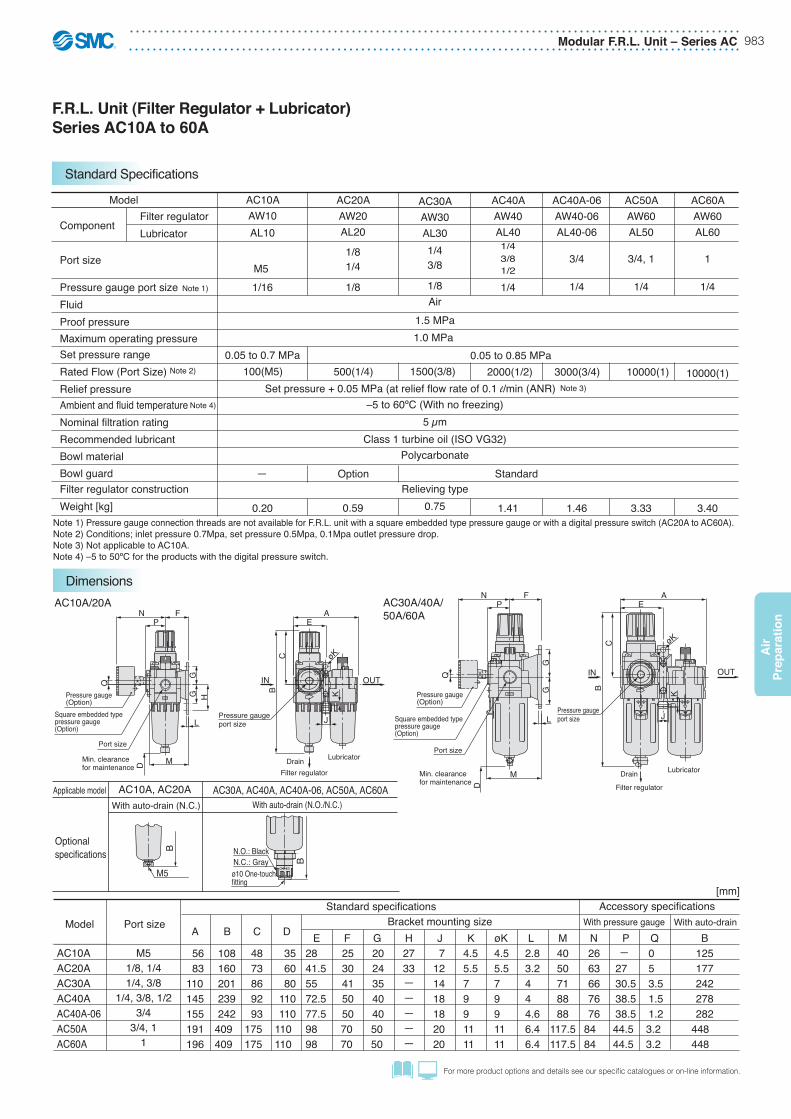
F.R.L. Unit (Filter Regulator + Lubricator)Series AC10A to 60A
AC10AAW10AL10
M5 1/16
0.05 to 0.7 MPa
0.20
AC20AAW20AL20
1/81/4
1/8
0.59
AC30AAW30AL301/43/8
1/8Air
1.5 MPa1.0 MPa
–5 to 60ºC (With no freezing)5 μm
Class 1 turbine oil (ISO VG32)Polycarbonate
Relieving type0.75
AC40AAW40AL401/43/81/2
1/4
1.41
AC40A-06AW40-06AL40-06
3/4
1/4
1.46Note 1) Pressure gauge connection threads are not available for F.R.L. unit with a square embedded type pressure gauge or with a digital pressure switch (AC20A to AC60A).Note 2) Conditions; inlet pressure 0.7Mpa, set pressure 0.5Mpa, 0.1Mpa outlet pressure drop.Note 3) Not applicable to AC10A.Note 4) –5 to 50ºC for the products with the digital pressure switch.
Model
Component
Port size
Pressure gauge port sizeFluidProof pressureMaximum operating pressureSet pressure rangeRated Flow (Port Size)Relief pressureAmbient and fluid temperatureNominal filtration ratingRecommended lubricantBowl materialBowl guardFilter regulator constructionWeight [kg]
Filter regulatorLubricator
Set pressure + 0.05 MPa (at relief flow rate of 0.1 l/min (ANR)
— Option Standard
0.05 to 0.85 MPa
AC30A/40A/50A/60A
AC10A/20A
OUTOUT
L
øK
L
øK
F
M
K
J
E
J
K
E
H
P
P
D
D
Q
Q
BC
N
BC
AN
GG
M
F
GG
A
INOUTIN
OUT
Pressure gaugeport size
Lubricator
Filter regulatorDrain
Pressure gauge(Option)
Square embedded typepressure gauge(Option)
Port size
Pressure gaugeport size
Lubricator
Filter regulator
DrainMin. clearancefor maintenance
Square embedded typepressure gauge(Option)
Pressure gauge(Option)
Port sizeMin. clearancefor maintenance
B
BN.C.: GrayN.O.: Black
M5 O S
ø10 One-touch fitting
O
S
AC10A, AC20A AC30A, AC40A, AC40A-06, AC50A, AC60AWith auto-drain (N.C.) With auto-drain (N.O./N.C.)
Applicable model
Optionalspecifications
100(M5) 500(1/4) 1500(3/8) 2000(1/2) 3000(3/4)
AC50AAW60AL50
3/4, 1
1/4
3.33
10000(1)
AC60AAW60AL60
1
1/4
10000(1)
3.40
AC10AAC20AAC30AAC40AAC40A-06AC50AAC60A
M51/8, 1/41/4, 3/8
1/4, 3/8, 1/23/4
3/4, 11
A
56 83110145155191196
B
108 160 201 239 242 409 409
C
48 73 86 92 93 175 175
D
35 60 80 110 110 110 110
E2841.55572.577.59898
F 25 30 41 50 50 70 70
G 20 24 35 40 40 50 50
H2733—————
J 7121418182020
øK4.55.57991111
L2.83.2444.66.46.4
N 26 63 66 76 76 84 84
P — 27 30.5 38.5 38.5 44.5 44.5
Q 0 5 3.5 1.5 1.2 3.2 3.2
B 125 177 242 278 282 448 448
K4.55.57991111
M4050718888
117.5117.5
Model Port sizeStandard specifications
Bracket mounting sizeAccessory specifications
[mm]
With pressure gauge With auto-drain
Note 2)
Note 1)
Note 4)
Note 3)
Standard Specifications
Dimensions
Series AC – Modular F.R.L. Unit984
Air
Prep
aration
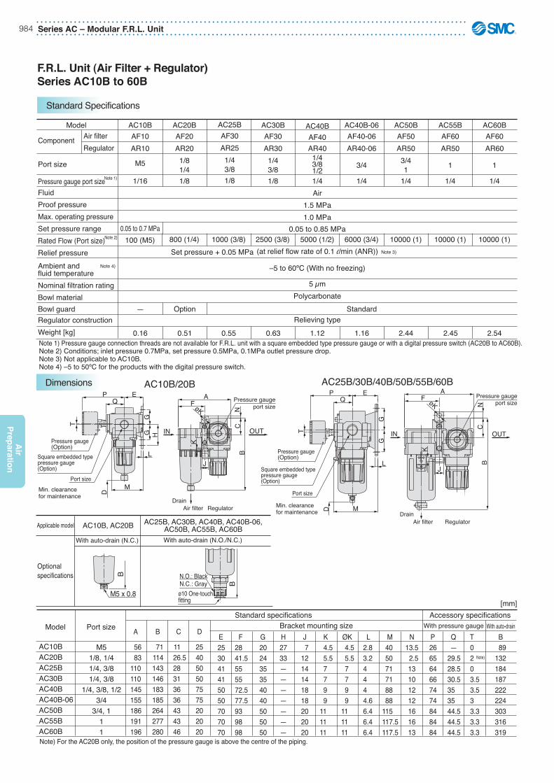
AC10BAF10AR10
M5
1/16
0.05 to 0.7 MPa
0.16
—
AC20BAF20AR201/81/41/8
AC25BAF30AR251/43/81/8
AC30BAF30AR301/43/81/8
AC40BAF40AR401/43/81/21/4Air
1.5 MPa1.0 MPa
0.05 to 0.85 MPa
(at relief flow rate of 0.1 l/min (ANR))
–5 to 60ºC (With no freezing)
5 μmPolycarbonate
Relieving type
AC40B-06AF40-06AR40-06
3/4
1/4
AC50BAF50AR503/41
1/4
AC55BAF60AR50
1
1/4
AC60BAF60AR60
1
1/4
Model
Component
Port size
Pressure gauge port sizeFluidProof pressureMax. operating pressureSet pressure rangeRated Flow (Port size)Relief pressureAmbient andfluid temperatureNominal filtration ratingBowl materialBowl guardRegulator constructionWeight [kg]
Air filterRegulator
Set pressure + 0.05 MPa
0.51 0.55 0.63 1.12 1.16
Option Standard
2.44 2.45 2.54
AC25B/30B/40B/50B/55B/60BAC10B/20B
L
øK N
E
M
F
K
J
QP
T
D
GG
BC
A
IN OUT
Square embedded typepressure gauge(Option)
Min. clearancefor maintenance
Port size
Pressure gauge(Option)
Pressure gaugeport size
RegulatorAir filterDrain
L
øK N
H
K
J
FQP
T
BC
D
M
E
GG
A
OUTIN
Pressure gaugeport size
RegulatorAir filterDrain
Square embedded typepressure gauge(Option)
Port size
Pressure gauge(Option)
Min. clearancefor maintenance
B
BN.C.: GrayN.O.: Black
M5 x 0.8O S
ø10 One-touch fitting
O
S
AC10B, AC20B AC25B, AC30B, AC40B, AC40B-06,AC50B, AC55B, AC60B
With auto-drain (N.C.) With auto-drain (N.O./N.C.)
Applicable model
Optionalspecifications
AC10BAC20BAC25BAC30BAC40BAC40B-06AC50BAC55BAC60B
M51/8, 1/41/4, 3/81/4, 3/8
1/4, 3/8, 1/23/4
3/4, 111
A
56 83110110145155186191196
B
71 114 143 146 183 185 264 277 280
C
11 26.5 28 31 36 36 43 43 46
D
25 40 50 50 75 75 20 20 20
E 25 30 41 41 50 50 70 70 70
F2841.5555572.577.5939898
G 20 24 35 35 40 40 50 50 50
H2733———————
J 71214141818202020
K 4.5 5.5 7 7 9 9111111
ØK 4.5 5.5 7 7 9 9111111
M 40 50 71 71 88 88 115 117.5 117.5
L2.83.24444.66.46.46.4
N13.5 2.513101212161613
P 26 65 64 66 74 74 84 84 84
Q — 29.5 28.5 30.5 35 35 44.5 44.5 44.5
T 0 2 Note)
0 3.5 3.5 3 3.3 3.3 3.3
B 89 132 184 187 222 224 303 316 319
Model Port sizeStandard specifications
Bracket mounting sizeAccessory specifications
[mm]
With pressure gauge With auto-drain
100 (M5) 800 (1/4) 1000 (3/8) 2500 (3/8) 5000 (1/2) 6000 (3/4) 10000 (1) 10000 (1) 10000 (1)
Note 1) Pressure gauge connection threads are not available for F.R.L. unit with a square embedded type pressure gauge or with a digital pressure switch (AC20B to AC60B).Note 2) Conditions; inlet pressure 0.7MPa, set pressure 0.5MPa, 0.1MPa outlet pressure drop.Note 3) Not applicable to AC10B.Note 4) –5 to 50ºC for the products with the digital pressure switch.
Note 1)
Note 2)
Note 4)
Note) For the AC20B only, the position of the pressure gauge is above the centre of the piping.
Note 3)
F.R.L. Unit (Air Filter + Regulator)Series AC10B to 60B
Standard Specifications
Dimensions

Modular F.R.L. Unit – Series AC 985
Air
Pre
par
atio
n
For more product options and details see our specifi c catalogues or on-line information.
AC20CAF20
AFM20AR201/81/41/8
200
0.74
AC25CAF30
AFM30AR251/43/81/8
450
0.88
AC30CAF30
AFM30AR301/43/81/8Air
1.5 MPa1.0 MPa0.05 MPa
0.05 to 0.85 MPa450
Set pressure + 0.05 MPa (at relief flow rate of 0.1 l/min (ANR))–5 to 60ºC (With no freezing)
AF: 5 μm; AFM: 0.3 μm (99.9% filtered particle size)Maximum 1.0 mg/m3 (ANR) (approx. 0.8 ppm)
Polycarbonate
Relieving type0.95
AC40CAF40
AFM40AR401/43/81/21/4
1100
1.76
AC40C-06AF40-06
AFM40-06AR40-06
3/4
1/4
1100
1.83
Standard
Model
Component
Port size
Pressure gauge port sizeFluidProof pressureMaximum operating pressureMinimum operating pressureSet pressure rangeRated flow [l/min (ANR)]Relief pressureAmbient and fluid temperatureNominal filtration ratingOutlet side oil mist concentrationBowl materialBowl guardFilter regulator constructionWeight [kg]
Air filterMist separatorRegulator
Option
AC25C/30C/40C
AC20C
H
PØL
J
M
L
K
FE
BC
A
D
N
H
U
TGQ
Air filter Mist separator Regulator
Drain Drain
Port size
Square embedded typepressure gauge (Option)
Pressure gauge(Option)
Pressure gaugeport size
Min. clearancefor maintenance
IN OUT
H
P
ØL
G
M
N
L
K
FE
BC
A
D
QT
U
H
RegulatorMist separatorAir filter
OUTIN
Pressure gaugeport size
Drain Drain
Port size
Square embedded typepressure gauge (Option)
Min. clearancefor maintenance
Pressure gauge(Option)
AC20C AC25C, AC30C, AC40C, AC40C-06With auto-drain (N.C.) With auto-drain (N.O./N.C.)
B
M5 O S
Applicable model
Optionalspecifications
BN.C.: GrayN.O.: Black
ø10 One-touch fitting
O
S
Model Port size
Standard specificationsBracket mounting size
Accessory specifications[mm]
With pressure gauge Withauto drain
AC20CAC25CAC30CAC40CAC40C-06
1/8, 1/41/4, 3/81/4, 3/8
1/4, 3/8, 1/23/4
A
126167167220235
B
114 143 146 183 185
C
26.5 28 31 36 36
D
45 50 50 75 75
E 41.5 55 55 72.5 77.5
F 43 57 57 75 80
G 30 41 41 50 50
H 24 35 35 40 40
J33————
K1214141818
L5.57 7 9 9
ØL5.57 7 9 9
M3.24 4 4 4.6
N5071718888
P 2.5 13 10 12 12
Q6564667474
T29.528.530.535 35
U2 Note)
0 3.53.53
B 132 184 187 222 224
Note 1) Pressure gauge connection threads are not available for F.R.L. unit with a square embedded type pressure gauge or with a digital pressure switch (AC20C to AC60C).Note 2) Conditions: Mist separator inlet pressure: 0.7 MPa; The rated flow varies depending on the inlet pressure. Keep the air flow within the rated flow to prevent an outflow of lubricant to the outlet side.Note 3) –5 to 50ºC for the products with the digital pressure switch. Note 4) When the compressor oil mist discharge concentration is 30 mg/m3 (ANR).Note 5) Bowl O-ring and other O-rings are slighttly lubricated.
Note 1)
Note 2)
Note 3)
Note) For the AC20C only, the position of the pressure gauge is above the centre of the piping.
Note 4) Note 5)
F.R.L. Unit (Air Filter + Mist Separator + Regulator)Series AC20C to 40C
Standard Specifications
Dimensions
Series AC – Modular F.R.L. Unit986
Air
Prep
aration
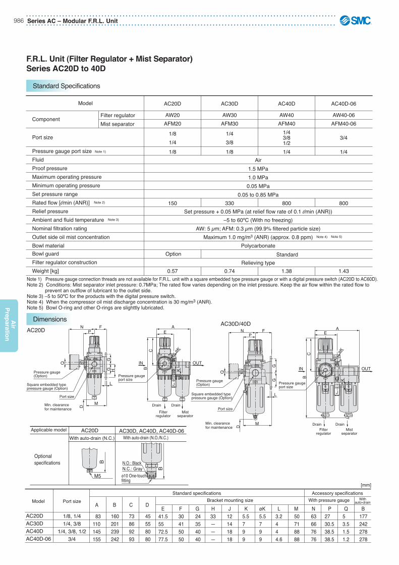
Model
Component
Port size
Pressure gauge port sizeFluidProof pressureMaximum operating pressureMinimum operating pressureSet pressure rangeRated flow [l/min (ANR)]Relief pressureAmbient and fluid temperatureNominal filtration ratingOutlet side oil mist concentrationBowl materialBowl guardFilter regulator constructionWeight [kg]
Filter regulatorMist separator
AC20D
AW20AFM20
1/81/41/8
150
0.57
AC30D
AW30AFM30
1/43/81/8
330
0.74
AC40D
AW40AFM40
1/43/81/21/4
800
1.38
AC40D-06
AW40-06AFM40-06
3/4
1/4
800
1.43
Air1.5 MPa1.0 MPa0.05 MPa
0.05 to 0.85 MPa
Set pressure + 0.05 MPa (at relief flow rate of 0.1 l/min (ANR))–5 to 60ºC (With no freezing)
AW: 5 μm; AFM: 0.3 μm (99.9% filtered particle size)Maximum 1.0 mg/m3 (ANR) (approx. 0.8 ppm)
Polycarbonate
Relieving typeOption Standard
AC20DAC30D/40D
L
øK
L
øK
F
M
GG
E
K
J
H
M
E
J
K
BC
A
D
Q
NP
CB
A
Q
FNP
D
GG
IN OUTIN OUT
Pressure gaugeport size
Drain Drain
Filterregulator
Mistseparator
Pressure gaugeport size
Drain DrainFilter
regulatorMist
separator
Pressure gauge(Option)
Port size
Square embedded typepressure gauge (Option)
Min. clearancefor maintenance
Pressure gauge(Option)
Port size
Square embedded typepressure gauge (Option)
Min. clearancefor maintenance
OUT
OUT
B
BN.C.: GrayN.O.: Black
M5 O S
ø10 One-touch fitting
O
S
AC20D AC30D, AC40D, AC40D-06With auto-drain (N.C.) With auto-drain (N.O./N.C.)
Applicable model
Optionalspecifications
AC20DAC30DAC40DAC40D-06
1/8, 1/41/4, 3/8
1/4, 3/8, 1/23/4
A
83110145155
B
160 201 239 242
C
73 86 92 93
D
45 55 80 80
E41.55572.577.5
F 30 41 50 50
G 24 35 40 40
H33———
J12141818
K5.5799
øK5.5799
M 50 71 88 88
L3.2444.6
N 63 66 76 76
P 27 30.5 38.5 38.5
Q 5 3.5 1.5 1.2
B 177 242 278 278
Model Port sizeStandard specifications
Bracket mounting sizeAccessory specifications
[mm]
With pressure gauge Withauto-drain
Note 1) Pressure gauge connection threads are not available for F.R.L. unit with a square embedded type pressure gauge or with a digital pressure switch (AC20D to AC60D).Note 2) Conditions: Mist separator inlet pressure: 0.7MPa; The rated flow varies depending on the inlet pressure. Keep the air flow within the rated flow to prevent an outflow of lubricant to the outlet side.Note 3) –5 to 50ºC for the products with the digital pressure switch. Note 4) When the compressor oil mist discharge concentration is 30 mg/m3 (ANR).Note 5) Bowl O-ring and other O-rings are slighttly lubricated.
Note 1)
Note 2)
Note 3)
Note 4) Note 5)
F.R.L. Unit (Filter Regulator + Mist Separator)Series AC20D to 40D
Standard Specifications
Dimensions
Modular F.R.L. Unit – Series AC 987
Air
Pre
par
atio
n
For more product options and details see our specifi c catalogues or on-line information.
∗ When more than one specification is required, indicate in ascending alphanumeric order.
0330 BDAF FAccessories
Port size
Body size
Thread type
Air filter
—*F
Metric thread (M5)G
10 20 30 40 50 60
Symbol
M5010203040610
PortsizeM51/81/43/81/23/41
10●
——————
20—●
●
————
30——●
●
———
40——●
●
●
●
—
50—————●
●
60——————●
Body size Note 1) A bracket is not assembled and supplied loose at the time of shipment. Including 2 mounting screws
Acces
sories
Accessory/Optional specificationsCombination
With bracketFloat type auto drain (N.C.)Float type auto drain (N.O.)
BCD
AF10B C D AF20 AF30 to 60Applicable filter Accessory
Sym
bol
: Combination available
: Combination not available : Varies depending on the model
Model
FluidMaximum operating pressureRated Flow Note1)
Ambient and fluid temperatureNominal filtration ratingBowl materialBowl guard
* Only body size 10
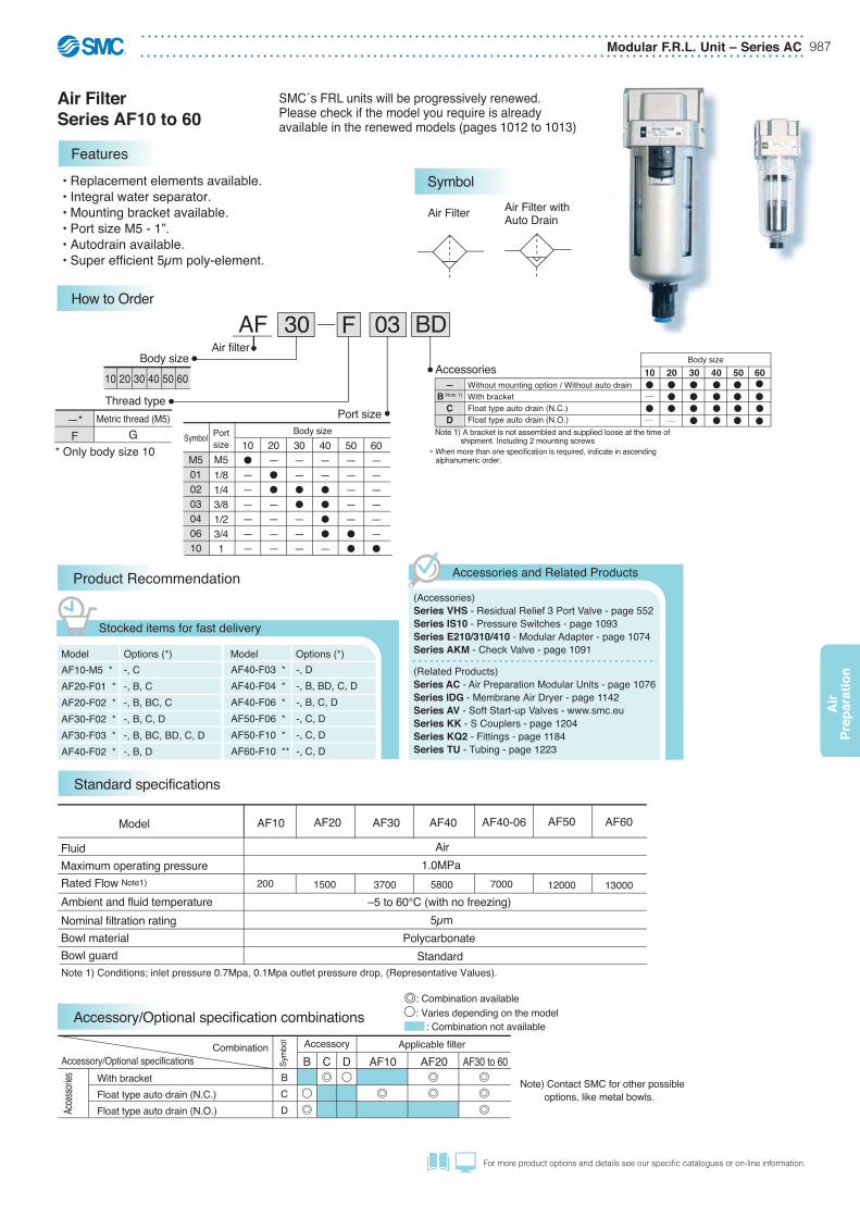
• Replacement elements available.• Integral water separator.• Mounting bracket available.• Port size M5 - 1”. • Autodrain available.• Super efficient 5μm poly-element.
Air1.0MPa
–5 to 60°C (with no freezing)5μm
PolycarbonateStandard
AF40 AF40-06 AF50 AF60AF10 AF20 AF30
5800 120007000 13000200 1500 3700
Note) Contact SMC for other possible options, like metal bowls.
Note 1) Conditions; inlet pressure 0.7Mpa, 0.1Mpa outlet pressure drop, (Representative Values).
Air Filter Series AF10 to 60
Features
How to Order
AF10-M5 *AF20-F01 *AF20-F02 *AF30-F02 *AF30-F03 *AF40-F02 *
Product Recommendation
Stocked items for fast delivery
-, C-, B, C-, B, BC, C-, B, C, D-, B, BC, BD, C, D-, B, D
Model Options (*) Model Options (*)AF40-F03 *AF40-F04 *AF40-F06 *AF50-F06 *AF50-F10 *AF60-F10 **
-, D-, B, BD, C, D-, B, C, D-, C, D-, C, D-, C, D
(Accessories)Series VHS - Residual Relief 3 Port Valve - page 552Series IS10 - Pressure Switches - page 1093Series E210/310/410 - Modular Adapter - page 1074Series AKM - Check Valve - page 1091
(Related Products)Series AC - Air Preparation Modular Units - page 1076Series IDG - Membrane Air Dryer - page 1142Series AV - Soft Start-up Valves - www.smc.euSeries KK - S Couplers - page 1204Series KQ2 - Fittings - page 1184Series TU - Tubing - page 1223
Accessories and Related Products
10 20 30 40 50 60Body size
—B Note 1)
CD
Symbol
Without mounting option / Without auto drainWith bracketFloat type auto drain (N.C.)Float type auto drain (N.O.)
Standard specifications
Accessory/Optional specification combinations
Air Filter Air Filter withAuto Drain
SMC´s FRL units will be progressively renewed.Please check if the model you require is alreadyavailable in the renewed models (pages 1012 to 1013)
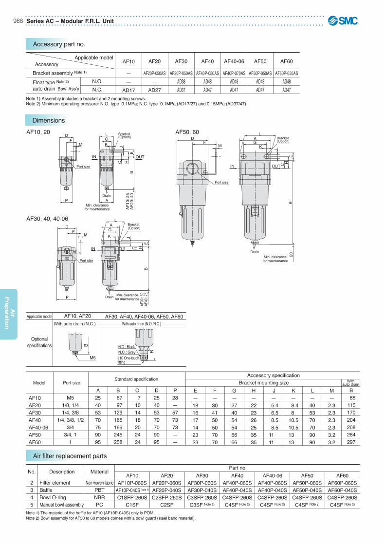
Series AC – Modular F.R.L. Unit988
Air
Prep
aration
A25405370759095
B 67 97 129 165 169 245 258
C 7 10 14 18 20 24 24
D25405370709095
P28—577373——
E—181617142323
F—304150507070
G—274054546666
H—222326253535
J — 5.4 6.5 8.5 8.5 11 11
K — 8.4 8 10.5 10.5 13 13
L—405370709090
M—2.32.32.32.33.23.2
B85
115170204208284297
AF10AF20AF30AF40AF40-06AF50AF60
Model Port sizeStandard specification
Bracket mounting sizeAccessory specification
Withauto drain
AF10, 20 AF50, 60
AF30, 40, 40-06 L
M
P
D
20
DF
MAG
K
J
BE
HC
BE
H
JC
FM
AGK
DF
A
JH
EB
C
LGK
OUTIN
OUT
OUTIN
OUT
Drain
Drain
Min. clearancefor maintenance
Min. clearancefor maintenance
OUTIN
OUT
o s
Bracket(Option)
Port size
Port size
DrainMin. clearance
for maintenance
Port size
Bracket(Option)
P
Bracket(Option)
L
B
BN.C.: GreyN.O.: Black
M5O S
ø10 One-touch fitting
O
S
AF10, AF20 AF30, AF40, AF40-06, AF50, AF60With auto drain (N.C.) With auto drain (N.O./N.C.)
Applicable model
Optionalspecifications
AF10
: 25
AF20
: 40
AF30
: 50
AF40
: 75
No.
2345
Part no.AF10
AF10P-060SAF10P-040S Note 1)
C1SFP-260SC1SF
AF20AF20P-060SAF20P-040SC2SFP-260S
C2SF
AF30AF30P-060SAF30P-040SC3SFP-260SC3SF Note 2)
AF40AF40P-060SAF40P-040SC4SFP-260SC4SF Note 2)
AF40-06AF40P-060SAF40P-040SC4SFP-260SC4SF Note 2)
AF50AF50P-060SAF50P-040SC4SFP-260SC4SF Note 2)
AF60AF60P-060SAF60P-040SC4SFP-260SC4SF Note 2)
Material
Non-woven fabricPBTNBRPC
Description
Filter elementBaffleBowl O-ringManual bowl assembly
Note 1) The material of the baffle for AF10 (AF10P-040S) only is POM.Note 2) Bowl assembly for AF30 to 60 models comes with a bowl guard (steel band material).
M51/8, 1/41/4, 3/8
1/4, 3/8, 1/23/4
3/4, 11
Applicable modelAccessory
Bracket assembly Note 1)
Float type Note 2)
auto drainN.O.N.C.
AF10
——
AD17
AF20
AF20P-050AS—
AD27
AF30
AF30P-050ASAD38AD37
AF40
AF40P-050ASAD48AD47
AF40-06
AF40P-070ASAD48AD47
AF50
AF50P-050ASAD48AD47
AF60
AF50P-050ASAD48AD47
Note 1) Assembly includes a bracket and 2 mounting screws.Note 2) Minimum operating pressure: N.O. type–0.1MPa; N.C. type–0.1MPa (AD17/27) and 0.15MPa (AD37/47).
Bowl Ass’y
Accessory part no.
Dimensions
Air filter replacement parts
Modular F.R.L. Unit – Series AC 989
Air
Pre
par
atio
n
For more product options and details see our specifi c catalogues or on-line information.
Note 1) Pressure gauge connection threads are not required for regulator with a square embedded type pressure gauge (AR20 to AR60).Note 2) Use a bushing (part no: 131368) when connecting the R 1/8 pressure gauge to the R 1/16 gauge port.Note 3) Except for AR10.Note 4) Conditions; Inlet pressure 0.7Mpa, set pressure 0.5Mpa, 0.1Mpa outlet pressure drop (Representative values).
AR 30 BEF 03
–∗F
∗ Only body size 10
Metric thread (M5)G
Body size
Regulator
Thread type
Port size
10�——————
20—��————
25——��———
30——��———
40——����—
50—————��
60——————�
Body size
10 20 25 30 40 50 60Symbol
M5010203040610
PortsizeM51/81/43/81/23/41
• Port size M5 - 1”.• “Q” and “P” compensation.• Built in gauge available.• Locking handle as standard.• Tamper proof cap as option.
AR10M5
0.05 to 0.7MPa
Rc 1/16 Note 2)
0.06
ModelPort sizesFluidProof pressureMaximum operating pressureSet pressure rangeRated flow (port size) Note4)
Pressure gauge port sizeRelief pressureAmbient and fluid temperatureConstructionWeight [kg]
AR201/8, 1/4
G 1/8
0.26
AR251/4, 3/8
G 1/8
0.21
AR401/4, 3/8, 1/2
G 1/4
0.44
AR40-063/4
G 1/4
0.47
AR503/4, 1
G 1/4
1.17
AR601
G 1/4
1.22
AR301/4, 3/8
Air1.5MPa1.0MPa
0.05 to 0.85MPa
G 1/8 Set pressure + 0.05MPa Note 3) [at relief flow rate of 0.1L/min (ANR)]
–5 to 60°C (with no freezing)Relieving type
0.29
Note 1)100(M5) 800(1/4) 1000(3/8) 5000(3/8) 6000(3/4) 10000(1) 10000(1)2500(3/8)
Regulator Series AR10 to 60
Features
How to Order
AR10-M5 *AR20-F01 *AR20-F02 *AR25-F02 *AR25-F03 *AR30-F02 *AR30-F03 *
Product Recommendation
Stocked items for fast delivery
–, B, BG, G, GH, H–, B, BE, BG, E, EH, G, H–, B, BE, BG, E, E3, E4, EH, G, H–, B, BE, BG, E, EH, G, H–, BG, E, G, H–, B, BE, BG, E, EH, G, GH, H–, B, BE, BG, E, E3, EH, G, H
Model Options (*) Model Options (*)AR40-F02 *AR40-F03 *AR40-F04 *AR40-F06 *AR50-F06 *AR50-F10 *AR60-F10 *
–, BE, E, G, H–, B, BE, E, EH, H–, BE, BG, E, EH, G, H–, BE, E, EH, G, H–, E, G–, B, E, G–, B, BG, E, G
(Accessories)Series VHS - Residual Relief 3 Port Valve - page 552Series IS10 - Pressure Switches - page 1093Series E210/310/410 - Modular Adapter - page 1074Series AKM - Check Valve - page 1091
(Related Products)Series AC - Air Preparation Modular Units - page 1076Series IDG - Membrane Air Dryer - page 1142Series AV - Soft Start-up Valves - www.smc.euSeries KK - S Couplers - page 1204Series KQ2 - Fittings - page 1184Series TU - Tubing - page 1223
Accessories and Related Products
10 20 25 30 40 50 60Body size
—B Note 2)
H
Without mounting option / Without Pressure gaugeWith bracketWith set nut (for panel fitting)
E
G
ME1 Note 3)
E2 Note 3)
E3 Note 3)
E4 Note 3)
Square embedded type pressure gauge (with limit indicator)Round type pressure gauge (without limit indicator)Round type pressure gauge (with limit indicator)Round type pressure gauge (with colour zone)Output: NPN output / Electrical entry: Wiring bottom entry Output: NPN output / Electrical entry: Wiring top entryOutput: PNP output / Electrical entry: Wiring bottom entry Output: PNP output / Electrical entry: Wiring top entry
Accessories Note 1)
Note 1)�Optional parts are not assembled and are supplied loose at the time of shipment (except for option E).Note 2) Assembly of a bracket and set nuts (AR10, AR20 to AR40)
Including 2 mounting screws for the AR50 and AR60Note 3) When choosing with H (panel mount), the installation space for lead wires will be
limited. In this case, select “wiring top entry” for the electrical entry. (Select “wiring bottom entry” when the semi-standard Y is chosen simultaneously.)
Standard specifications
Symbol
1 2
* When more than one specification is required, indicate in ascending alphanumeric order.
SMC´s FRL units will be progressively renewed.Please check if the model you require is alreadyavailable in the renewed models (pages 1014 to 1015)

Series AC – Modular F.R.L. Unit990
Air
Prep
aration
Note) For AR20 only, the position of the pressure gauge is above the centre of the piping.
Model
AR10AR20AR25AR30AR40AR40-06AR50AR60
Port sizes
M51/8, 1/41/4, 3/81/4, 3/8
1/4, 3/8, 1/23/4
3/4, 11
Standard specificationAccessory specification
With pressure gauge Bracket mounting size Panel mountA2540535370759095
B 58 94 101 116 128 129 169 176
C 11 26.5 28 31 36 36 43 46
D2557555968688787
E2665646674748484
F — 29.5 28.5 30.5 35 35 44.5 44.5
G 0
2 Note)
0 3.5 3.5 3 3.3 3.3
J2530304150507070
K2834344054546666
L 30 44 44 46 54 56 65.8 65.8
M 4.5 5.4 5.4 6.5 8.5 8.5 11 11
N 6.5 15.4 15.4 8 10.5 10.5 13 13
P4055555370709090
V—66777——
Q 2 2.3 2.3 2.3 2.3 2.3 3.2 3.2
S 18 25 26 31 35.5 37 —
—
T 18.5 28.5 32.5 38.5 42.5 42.5 —
—
U—1416192121——
AR10 to 40
AR50, 60
IN OUT
Port size
Pressure gauge(option)
Pressure gaugeport
OUTIN
Port size
Pressure gaugeport
Square embedded typepressure gauge (option)
Square embedded typepressure gauge (option)
CS
L B
JE
Q
G
A
KP
M
N
JF
E
CL B
Q
G
D
U
V
A
KP
M
N
D
F
T
Pressure gauge(option)
Bracket(option)
Bracket(option)
Panel fitting dimension
Plate thicknessAR10 to AR30: Max. 3.5AR40: Max. 5
IN OUT
Applicable ModelSpares Kit
AR10KT-AR10
AR20KT-AR20-02
AR25KT-AR25-02
AR30KT-AR30-03
AR40-04KT-AR40-04
AR40-06KT-AR40-06
AR50KT-AR50-06
AR60KT-AR60
Spare kit includes valve assembly, valve guide assembly and diaphragm assembly.
Note): If panel mounting, order a neck nut separately.
: Combination available: Varies depending on the model
: Combination not available
Accessory/Optional specificationsCombination
With bracket (with neck nut)Square embedded or digital pressure gaugeRound pressure gauge
Accessory Applicable regulatorSymbol
BEG
B E G AR10 AR20 to 40 AR50 to 60
Acce
ssorie
s
Applicable modelAccessoryBracket assembly Note 1)
Set nutPressuregauge
Round1MPa
AR10 AR20 AR25 AR30 AR40 AR40-06 AR50 AR60
Accessory part no.
Note 1) Assembly includes a bracket and neck nuts.Note 2) Includes one O-ring and 2 mounting screws.Note 3) Assembly includes a bracket and 2 mounting screws.
Note 2)Squareembedded type
AR10P-270ASAR10P-260SG27-10-R1
—
AR20P-270ASAR20P-260SG36-10-01GC3-10AS
AR25P-270ASAR25P-260SG36-10-01GC3-10AS
AR30P-270ASAR30P-260SG36-10-01GC3-10AS
AR40P-270ASAR40P-260SG46-10-02GC3-10AS
AR40P-270ASAR40P-260SG46-10-02GC3-10AS
AR50P-270AS Note 3)
–G46-10-02GC3-10AS
AR50P-270AS Note 3)
–G46-10-02GC3-10AS
Accessory/Optional specification combinations
Dimensions
Replacement parts

Modular F.R.L. Unit – Series AC 991
Air
Pre
par
atio
n
For more product options and details see our specifi c catalogues or on-line information.
Regulator with a built-in mechanism that ensures a quickrelease of the outlet air pressure (built-in check valve withback flow mechanism).
∗ AR10 comes with a back flow mechanism as a standard feature.Note 1) Set the inlet pressure 0.05MPa or higher than the set pressure.Note 2) Pressure gauge connection threads are not required for regulators with a square embedded type pressure gauge (AR20K to AR60K).Note 3) Conditions; inlet pressure 0.7Mpa, set pressure 0.5Mpa, 0.1Mpa outlet pressure drop (Representative values).
AR 30 K F 03 BE
Accessories Note 1)
Note 1)�Optional parts are not assembled and are supplied loose at the time of shipment (except for option E).Note 2) Assembly of a bracket and set nuts (AR10, AR20 to AR40)
Including 2 mounting screws for the AR50 and AR60Note 3) When choosing with H (panel mount), the installation space for lead wires will be limited. In this
case, select “wiring top entry” for the electrical entry. (Select “wiring bottom entry” when the semi-standard Y is chosen simultaneously.)
Regulator
With back flow mechanism
Body size
Port size
Note) AR10 comes with a back flow mechanism as a standard feature.If the set pressure is below 0.15MPa, back flow may not occur. When a backflow mechanism is required with a set pressure of less than 0.15MPa, contact SMC.
20��————
25—��———
30—��———
40—����—
50————��
60—————�
Body size
20 25 30 40 50 60
Symbol
010203040610
Portsize1/81/43/81/23/41
Example 1) When the pressure in the rear and the front of the cylinder differs:
Example 2) When the air supply is cut off and releasing the inlet pressure to the atmosphere, the residual pressure release of the outlet side can be ensured for a safety purpose.
Circuit diagram
Circuit diagram
• Port size M5 - 1” .• “Q” and “P” compensation.• Built in gauge available.• Locking handle as standard.• Tamper proof cap as option.
Air1.5MPa1.0MPa
0.05 to 0.85MPa
Set pressure + 0.05MPa [at relief flow rate of 0.1l/min (ANR)]–5 to 60°C (with no freezing)
Relieving type
AR20K
G 1/8800(1/4)
0.16
AR25K
G 1/81000(3/8)
0.21
AR30K
G 1/82500(3/8)
0.30
AR50K
G 1/410000(1)
1.17
AR40K
G 1/45000(1/2)
0.45
AR40K-06
G 1/46000(3/4)
0.48
AR60K
G 1/410000(1)
1.22
FluidProof pressureMaximun operating pressureSet pressure range Note1)
Pressure gauge port size Note2)
Rated Flow (Port size) Note 3)
Relief pressureAmbient and fluid temperatureConstructionWeight [kg]
Model
Regulator: Modular type withBack Flow MechanismSeries AR20K to 60K
Features
How to Order
Symbol
20 25 30 40 50 60
Body size
—B Note 2)
H
Without mounting option / Without pressure gaugeWith bracketWith set nut (for panel fitting)
E
G
ME1 Note 3)
E2 Note 3)
E3 Note 3)
E4 Note 3)
Square embedded type pressure gauge (with limit indicator)Round type pressure gauge (without limit indicator)Round type pressure gauge (with limit indicator)Round type pressure gauge (with colour zone)Output: NPN output / Electrical entry: Wiring bottom entry Output: NPN output / Electrical entry: Wiring top entryOutput: PNP output / Electrical entry: Wiring bottom entry Output: PNP output / Electrical entry: Wiring top entry
(Accessories)Series VHS - Residual Relief 3 Port Valve - page 552Series IS10 - Pressure Switches - page 1093Series E210/310/410 - Modular Adapter - page 1074Series AKM - Check Valve - page 1091
(Related Products)Series AC - Air Preparation Modular Units - page 1076Series IDG - Membrane Air Dryer - page 1142Series AV - Soft Start-up Valves - www.smc.euSeries KK - S Couplers - page 1204Series KQ2 - Fittings - page 1184Series TU - Tubing - page 1223
Accessories and Related Products
AR20K-F01 *AR20K-F02 *AR25K-F02 *AR30K-F02 *AR30K-F03 *AR40K-F03 *
Product Recommendation
Stocked items for fast delivery
–, B, BE, BG, E, EH, GH, H–, B, BE, BG, E, EH, H–, BE, BG, E, H–, BE, BG, E, G, H–, B, BE, BG, E, H–, BE, E, H
Model Options (*)AR40K-F04 *AR40K-F06*AR50K-F06*AR50K-F10*AR60K-F10*
–, BE, E, H–, E, H–––, BE, E
Model Options (*)
Standard specifications
Threadtype
F G
* When more than one specification is required, indicate in ascending alphanumeric order.
SMC´s FRL units will be progressively renewed.Please check if the model you require is alreadyavailable in the renewed models (pages 1014 to 1015)

Series AC – Modular F.R.L. Unit992
Air
Prep
aration
Model
AR20KAR25KAR30KAR40KAR40K-06AR50KAR60K
Port size
1/8, 1/41/4, 3/81/4, 3/8
1/4, 3/8, 1/23/4
3/4, 11
Standard specification Accessory specificationWith pressure gauge Bracket mounting size Panel mount
A40535370759095
B 94 101 116 128 129 169 176
C 26.5 28 31 36 36 43 46
D57555968688787
E65646674748484
F 29.5 28.5 30.5 35 35 44.5 44.5
G2 Note)
03.53.533.33.3
J30304150507070
K34344054546666
U1416192121——
V66777——
L 44 44 46 54 56 65.8 65.8
M 5.4 5.4 6.5 8.5 8.5 11 11
N 15.4 15.4 8 10.5 10.5 13 13
P55555370709090
Q 2.3 2.3 2.3 2.3 2.3 3.2 3.2
S 25 26 31 35.5 37 — —
T 28.5 32.5 38.5 42.5 42.5 — —
Note) For AR20K only, the position of the pressure gauge is above the centre of the piping.
AR20K to 40K
AR50K, 60K
Applicable ModelSpares Kit
AR20KKT-AR20K-02
AR25KKT-AR25K-02
AR30KKT-AR30K-03
AR40K-04KT-AR40K-04
AR40K-06KT-AR40K-06
AR50KKT-AR50K-06
AR60KKT-AR60K
Spare kit includes valve assembly, valve guide assembly, diaphragm assembly and check valve assembly
Square embedded typepressure gauge (option)
Square embedded typepressure gauge (option)
Bracket(option)
Bracket(option)
Pressure gauge(option)
Pressure gauge(option)
IN OUT
Port size
Panel fitting dimension
OUTIN
Port size
Pressure gaugeport size
Plate thicknessAR20K to AR30K: Max. 3.5AR40K: Max. 5
M
N
CS
L B
JE
G
Q
A
KP
KP
M
N
CL
B
Q
J
G
A
T
F
D
D
FE
INOUT
U
V
Pressure gaugeport size
NOTE: If panel mounting, order a neck nut separately.
Accessory
Bracket assembly Note 1)
Set nut
Pressuregauge
1.0MPa
0.2MPa
Applicable model AR20KAR20P-270ASAR20P-260S
G36-10-01GC3-10ASG36-2-01GC3-2AS
AR25KAR25P-270ASAR25P-260S
G36-10-01GC3-10ASG36-2-01GC3-2AS
AR30KAR30P-270ASAR30P-260S
G36-10-01GC3-10ASG36-2-01GC3-2AS
AR40KAR40P-270ASAR40P-260S
G46-10-02GC3-10ASG46-2-02GC3-2AS
AR40K-06AR40P-270ASAR40P-260S
G46-10-02GC3-10ASG46-2-02GC3-2AS
AR50KAR50P-270AS Note 3)
–
G46-10-02GC3-10ASG46-2-02GC3-2AS
AR60KAR50P-270AS Note 2)
–
G46-10-02GC3-10ASG46-2-02GC3-2AS
Note 1) Assembly includes a bracket and neck nuts.Note 2) Assembly includes a bracket and 2 mounting screws.Note 3) Includes one O-ring and 2 mounting screws.
Round
Round
Note 3)Squareembedded type
Note 3)Squareembedded type
Accessory part no.
Dimensions
Replacement parts

Modular F.R.L. Unit – Series AC 993
Air
Pre
par
atio
n
For more product options and details see our specifi c catalogues or on-line information.
Accessory/Optional specificationsCombination
With bracket BAL10B AL20 AL30 to 60Applicable lubricatorAccessory
Symb
ol
AL10—
AL20AF20P-050AS
AL30AF30P-050AS
AL40AF40P-050AS
AL40-06AF40P-070AS
AL50AF50P-050AS
AL60AF50P-050AS
Applicable modelAccessoryBracket assembly Note)
∗ The part number for Bracket assembly for 1000cm3 is AF50P-050AS (applicable to AL30 to AL60).Note) Assembly includes a bracket and 2 mounting screws.
Accessory
: Combination available: Varies depending on the model
: Combination not available
AL30
1/4: 303/8: 40
55
0.24
ModelFluidProof pressureMaximum operating pressure
Minimum dripping flow rate [L/min (ANR)]
Oil capacity [cm3]
Recommended lubricantAmbient and fluid temperatureBowl materialBowl guardWeight [kg]
AL10
4
7
—0.07
AL20
15
25
Option0.20
AL40Air
1.5MPa1.0MPa1/4: 303/8: 401/2: 50
135
Class 1 turbine oil (ISO VG32)–5 to 60°C (with no freezing)
Polycarbonate
0.47
AL40-06
50
135
Standard0.52
AL50
190
135
1.06
AL60
220
135
1.13
Note 1)
Note 1) • The flow rate is 5 drips/min under the following conditions: Inlet pressure of 0.5MPa; Class 1 turbine oil (ISO VG32); Temperature at 20˚C; Oil adjustment valve fully open.• Use air consumption flow rate for minimum dripping flow rate.
Thread type
AL 30 03F
—
F
Metric thread(M5)G
Lubricator
Body sizePort size
10 20 30 40 50 60 10
——————
20—
————
30——
———
40——
—
50—————
60——————
Body sizeSymbol
M5010203040610
PortsizeM51/81/43/81/23/41
• Port size M5 - 1”.• Precise adjustment.• Uniform lubrication even at extremely low flow rates.• Over 97% of atomised oil particles <10 microns.• Sight dome for visual setting.• Built in check valve prevents oil falling back into bowl during no air consumption which could cause ‘dry period’ running.• Mounting bracket available.
Rated Flow (Port size) Note 2) 7000 (3/8)100 (ms) 4000 (1/4) 8000 (1/2) 8000 (3/4) 14000 (1) 15000 (1)
Note: Contact SMC for other options like metal bowl or 1 litre tank.
Note 2) Inlet pressure 0.7MPa, 0.1 MPa outlet pressure drop (Representative values).
Lubricator Series AL10 to 60
Features
How to Order
Symbol
Standard specifications
(Accessories)Series VHS - Residual Relief 3 Port Valve - page 552Series IS10 - Pressure Switches - page 1093Series E210/310/410 - Modular Adapter - page 1074Series AKM - Check Valve - page 1091
(Related Products)Series AC - Air Preparation Modular Units - page 1076Series IDG - Membrane Air Dryer - page 1142Series AV - Soft Start-up Valves - www.smc.euSeries KK - S Couplers - page 1204Series KQ2 - Fittings - page 1184Series TU - Tubing - page 1223
Accessories and Related Products
AL10-M5AL20-F01AL20-F02AL30-F02
Product Recommendation
Stocked items for fast delivery
AL30-F03AL40-F02AL40-F03AL40-F04
AL40-F03AL50-F02AL50-F03AL60-F04
Accessory/Optional specification combinations
Accessory part no.
SMC´s FRL units will be progressively renewed.Please check if the model you require is alreadyavailable in the renewed models (pages 1016 to 1017)

Series AC – Modular F.R.L. Unit994
Air
Prep
aration
Model
AL10AL20AL30AL40AL40-06AL50AL60
Port size Standard specificationAccessory specificationBracket mounting size
25405370759095
A B 77 115 142 176 176 250 268
C26363840384145
D25405370709095
P28—577373——
R 35 60 80 110 110 110 110
F—304150507070
E—————4747
G—274054546666
H—222326253535
J — 5.4 6.5 8.5 8.5 11 11
K — 8.4 8 10.5 10.5 13 13
L—405370709090
M—2.32.32.32.33.23.2
AL50, 60AL30, 40
AL10 AL20
OUT
OUTIN
Port sizeBracket(option)
Bracket(option) Bracket
(option)
Min. clearancefor maintenance
OUT
OUTIN
Port size
Min. clearancefor maintenance
OUT
OUTIN
Port size
Min. clearancefor maintenance
Min. clearancefor maintenance
OUT
IN
Port size
A
P
CB
R
J H CB
R
KGL
A
MF
D
KG
A
J H CB
R
M
P
FD L
KGL
JH C
BR
MF
D
E
A
OUT
Applicable ModelSpares Kit
AL10KT-AL10
AL20KT-AL20-02
AL30KT-AL30-03
AL40KT-AL40-04
AL50KT-AL50-06
AL60KT-AL60
M51/8, 1/41/4, 3/8
1/4, 3/8, 1/23/4
3/4, 11
AL10 spares kit includes sight dome assemblyAL20 to AL60 spares kit includes sight dome assembly, lubricator plug assembly, damper retainer assembly and damper.
Dimensions
Replacement parts

Modular F.R.L. Unit – Series AC 995
Air
Pre
par
atio
n
For more product options and details see our specifi c catalogues or on-line information.
Integrated filter and regulator unitssave space and require less piping.
Direct operated, relieving type
03 BE30AW F
Accessories Note 1)
Thread typeMetric thread (M5)
G
Port sizeBody size
Filterregulator
10 20 30 40 60 10�——————
20—��————
30——��———
40——����—
Body sizeSymbol
M5010203040610
PortsizeM51/81/43/81/23/41
–∗F
∗ Only body size 10
60————���
ModelPort sizesFluidProof pressureMaximum operating pressureSet pressure rangePressure gauge port size Note 1)
Relief pressureRated Flow (Port size) Note 4 )
Ambient and fluid temperatureNominal filtration ratingDrain capacity [cm3]Bowl materialBowl guardConstructionWeight [kg]
AW40-063/4
G 1/4
45
0.75
AW10M5
0.05 to 0.7MPa1 / 16 Note 2)
2.5
—
0.09
AW401/4, 3/8, 1/2
G 1/4
45
Standard
0.72
AW201/8, 1/4
G 1/8
8
Option
0.32
AW301/4, 3/8
Air1.5MPa1.0MPa
0.05 to 0.85MPaG 1/8
Set pressure + 0.05MPa Note 3) [at relief flow rate of 0.1L/min (ANR)]
–5 to 60ºC (with no freezing)5 μm25
Polycarbonate
Relieving type0.40
Note 1) Pressure gauge connection threads are not required for regulators with a square embedded type pressure gauge (AW20 to AW40).Note 2) Use a bushing (part no: 131368) when connecting R 1/8 pressure gauge to R 1/16 gauge port.Note 3) Not applicable to AW10.Note 4) Conditions; inlet pressure 0.7Mpa, set pressure 0.54 Mpa, 0.1Mpa outlet pressure drop.
AW603/4, 1
G 1/4
45
2.0
• Port size M5 - 1”.• Quick release bowl guard on some sizes.• Choice of manual or automatic condensate drain.• 5μm filter element.• Built in gauge available.• Locking handle as standard.• Tamper proof cap as option.
3800(3/4)100(M5) 2000(1/2)500(1/4) 1500(3/8) 14000(1)
Filter Regulator Series AW10 to 60
Features
How to Order
Symbol
(Accessories)Series VHS - Residual Relief 3 Port Valve - page 552Series IS10 - Pressure Switches - page 1093Series E210/310/410 - Modular Adapter - page 1074Series AKM - Check Valve - page 1091
(Related Products)Series AC - Air Preparation Modular Units - page 1076Series IDG - Membrane Air Dryer - page 1142Series AV - Soft Start-up Valves - www.smc.euSeries KK - S Couplers - page 1204Series KQ2 - Fittings - page 1184Series TU - Tubing - page 1223
Accessories and Related Products
Product Recommendation
Stocked items for fast delivery
AW10-M5 *AW20-F01 *AW20-F02 *AW30-F02 *
AW30-F03 *
AW40-F02 *AW40-F03 *
AW40-F04 *
AW40-F06 *AW60-F06 *AW60-F10 *
-, A, C, CH, H -, A, BC, BCE, BE, C, CE, CEH, CG, CGH, CH, E, EH, G, GH, H -, A, B, BC, BCE, BCE3, BCG, BE, BE3, BG, C, CE, CE3, CEH, CH, E, E3, EH, G, H -, A, B, BC, BCG, BD, BDE, BE, C, CE, D, DE, DEH, DH, E, EH, G, GH, H -, A, B, BCE, BDE, BDE3, BE, BE4, BG, C, CE, CE3, CH, D, DE, DE3, DEH, DG, DGH, DH, E, E3, EH, G, H -, A, D, DE, DH, E, EH, G -, A, BDE, BE, D, DE, DEH, DG, DH, E, H -, A, B, BC, BDE, BDG, BE, BG, C, CE, CEH, CG, CH, D, DE, DE3, DE4, DEH, DG, DGH, DH, E, E3, E4, EH, G, GH, H -, A, B, BE, C, CE, D, DE, DEH, DG, DH, E, EH, G, H -, A, D, E, G -, A, C, D, DE, E, G
Note 1)�Optional parts are not assembled and are supplied loose at the time of shipment (except for option C, D and E).Note 2) Assembly of a bracket and set nuts (AW10, AW20 to AW40)
Including 2 mounting screws for the AW60.Note 3) When choosing with H (panel mount), the installation space for lead wires will be limited.
In this case, select “wiring top entry” for the electrical entry.
10 20 30 40 60—
B Note 2)
HCDE
G
ME1 Note 3)
E2 Note 3)
E3 Note 3)
E4 Note 3)
Float type auto drain (N.C.)Float type auto drain (N.O.)Square embedded type pressure gauge (with limit indicator)Round type pressure gauge (without limit indicator)Round type pressure gauge (with limit indicator)Round type pressure gauge (with colour zone)Output: NPN output / Electrical entry: Wiring bottom entry Output: NPN output / Electrical entry: Wiring top entryOutput: PNP output / Electrical entry: Wiring bottom entry Output: PNP output / Electrical entry: Wiring top entry
Without mounting option / auto drain / pressure gaugeWith bracketWith set nut (for panel fitting)
Body size
Standard Specifications
1 2
Note) Contact SMC for other options like metal bowl or 1 litre tank.
* When more than one specification is required, indicate in ascending alphanumeric order.
SMC´s FRL units will be progressively renewed.Please check if the model you require is alreadyavailable in the renewed models (pages 1018 to 1019)

Series AC – Modular F.R.L. Unit996
Air
Prep
aration
AccessoryBracket assembly Note 1)
Set nut
Pressuregauge
Float typeauto drain
Applicable model
1.0MPa
0.2MPa
AW40-06AW40AW30AW20AW10
AR10P-270AS AR10P-260S G27-10-R1
— G27-10-R1 Note 2)
——
AD17
Round
Square embedded typeRound
Square embedded typeN.O.N.C.
AW20P-270ASAR20P-260SG36-10-01GC3-10ASG36-2-01GC3-2AS
—AD27
AR30P-270ASAR30P-260SG36-10-01GC3-10ASG36-2-01GC3-2AS
AD38AD37
AR40P-270ASAR40P-260SG46-10-02GC3-10ASG46-2-02GC3-2AS
AD48AD47
AR40P-270ASAR40P-260SG46-10-02GC3-10ASG46-2-02GC3-2AS
AD48AD47
Note 1) Assembly includes a bracket and set nuts.Note 2) For 1MPa.Note 3) Includes one O-ring and 2 mounting screws.Note 4) Minimum operating pressure: N.O. type–0.1MPa; N.C. type–0.1MPa (AD17/27) and 0.15MPa (AD37/47). Contact SMC regarding the specifications for PSI unit and F.
Note 4)
Note 3
Note 3)
Bowlass’y
AW60P-270AS-
G46-10-02GC3-10ASG46-2-02GC3-2AS
AD48AD47
AW60
Model
AW10AW20AW30AW40AW40-06AW60
Port sizeS
6.515.4
810.510.513
W18.528.538.542.542.5
-
B125177242278282448
Accessory specificationPanel mount With
auto drainU22.32.32.32.33.2
T405553707090
Q4.55.46.58.58.511
N283440545466
K05
3.51.51.23.3
J—27
30.538.538.543.5
H266366767684
G254055808080
E284057737395
D255259757595
C4873869293175
B108160201239242405
A254053707595
Standard specification
M253041505070
P304446545666
Y—14192121-
Z—6777-
V 18 30 31
35.5 37
-
With pressure gauge Bracket mounting size
AW30, 40, 60AW10, 20
W
Plate thicknessAW10, AW20: Max. 3.5
Panel fitting dimension
IN OUT
Y
Z
W
Plate thicknessAW30: Max. 3.5AW40: 5
Panel fitting dimension
IN OUT
Y
Z
V
DJ
G E
U
P
K
H M
Square embedded typepressure gauge (option)
Bracket(option)
Min. clearancefor maintenance
Port size
Pressure gauge(option)
OUT
V
DJ
G
E
P
U
K
H M
Square embedded typepressure gauge (option)
Bracket(option)
Port size
Pressure gauge(option)
Min. clearancefor maintenance
OUT
N
A
BC
Q
S
T
Pressure gaugeport size
O S
IN OUT
Drain
BC
NQ
S
T
A
Pressure gaugeport size
IN OUT
Drain
Applicable ModelSpares Kit
AW10KT-AW10
AW20KT-AW20-02
AW30KT-AW30-03
Spares kit includes valve assembly, diaphragm assembly and filter element
B
O S
M5 x 0.8
AW10, AW20With auto drain
(N.C.)Optional
specifications
Dimensions
Applicable model
B
O
S
N.O.: BlackN.C.: Greyø10 One-touch fitting
AW30, AW40, AW40-06, AW60With auto drain
(N.O./N.C.)
M51/8, 1/41/4, 3/8
1/4, 3/8, 1/23/4
3/4, 1
Applicable ModelSpares Kit
AW40-04KT-AW40-04
AL40-06KT-AW40-06
AW60KT-AW60-10
NOTE: If panel mounting, order a neck nut separately. NOTE: If panel mounting,
order a neck nut separately.
Acce
ssor
ies
CombinationAccessory/Optional specifications
With bracket (with neck nut)Float type auto drain (N.C.)Float type auto drain (N.O.)Square embedded type pressure gauge/digital gaugeRound pressure gauge
B C D E G AW10 AW20Accessory
BCDEG
AW30 to 60
: Combination available: Varies depending on the model
: Combination not available
Applicable filter regulator
Symb
ol
Accessory part no.
Dimensions
Replacement parts
Accessory/Optional specification combinations
Modular F.R.L. Unit – Series AC 997
Air
Pre
par
atio
n
For more product options and details see our specifi c catalogues or on-line information.
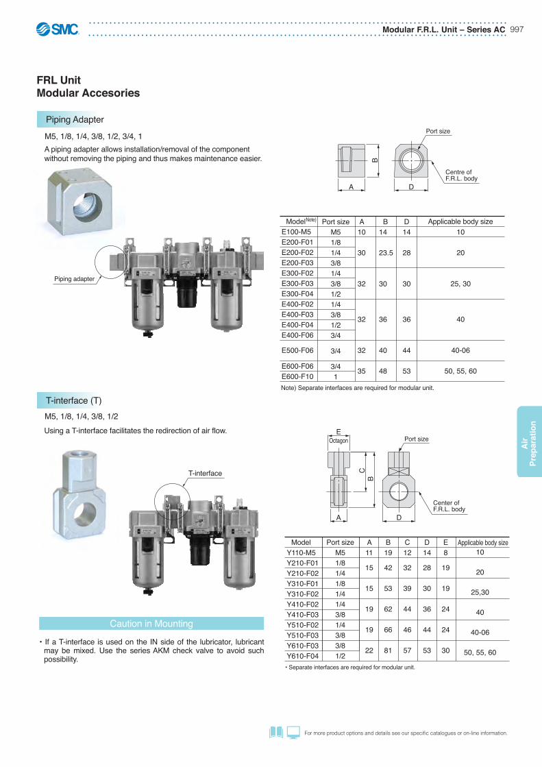
Applicable body sizePort sizeM51/81/43/81/43/81/21/43/81/23/4
3/4
3/41
D14
28
30
36
44
53
B14
23.5
30
36
40
48
A10
30
32
32
32
35
10
20
25,30
40
40-06
50, 55, 60
ModelY110-M5Y210-F01Y210-F02Y310-F01Y310-F02Y410-F02Y410-F03Y510-F02Y510-F03Y610-F03Y610-F04
Port sizeM51/81/41/81/41/43/81/43/83/81/2
M5, 1/8, 1/4, 3/8, 1/2, 3/4, 1
Caution in Mounting
A piping adapter allows installation/removal of the component without removing the piping and thus makes maintenance easier.
M5, 1/8, 1/4, 3/8, 1/2Using a T-interface facilitates the redirection of air flow.
C12
32
39
44
46
57
D14
28
30
36
44
53
E8
19
19
24
24
30
B19
42
53
62
66
81
A11
15
15
19
19
22
Note)
T-interface
Piping adapter
• Separate interfaces are required for modular unit.
•� If a T-interface is used on the IN side of the lubricator, lubricant may be mixed. Use the series AKM check valve to avoid such possibility.
Applicable body size
FRL UnitModular Accesories
B
DA
Centre ofF.R.L. body
Port size
BC
E
DA
Octagon Port size
Center ofF.R.L. body
Note) Separate interfaces are required for modular unit.
10
20
25, 30
40
40-06
50, 55, 60
Piping Adapter
T-interface (T)
ModelE100-M5E200-F01E200-F02E200-F03E300-F02E300-F03E300-F04E400-F02E400-F03E400-F04E400-F06
E600-F06E600-F10
E500-F06
Series AC – Modular F.R.L. Unit998
Air
Prep
aration
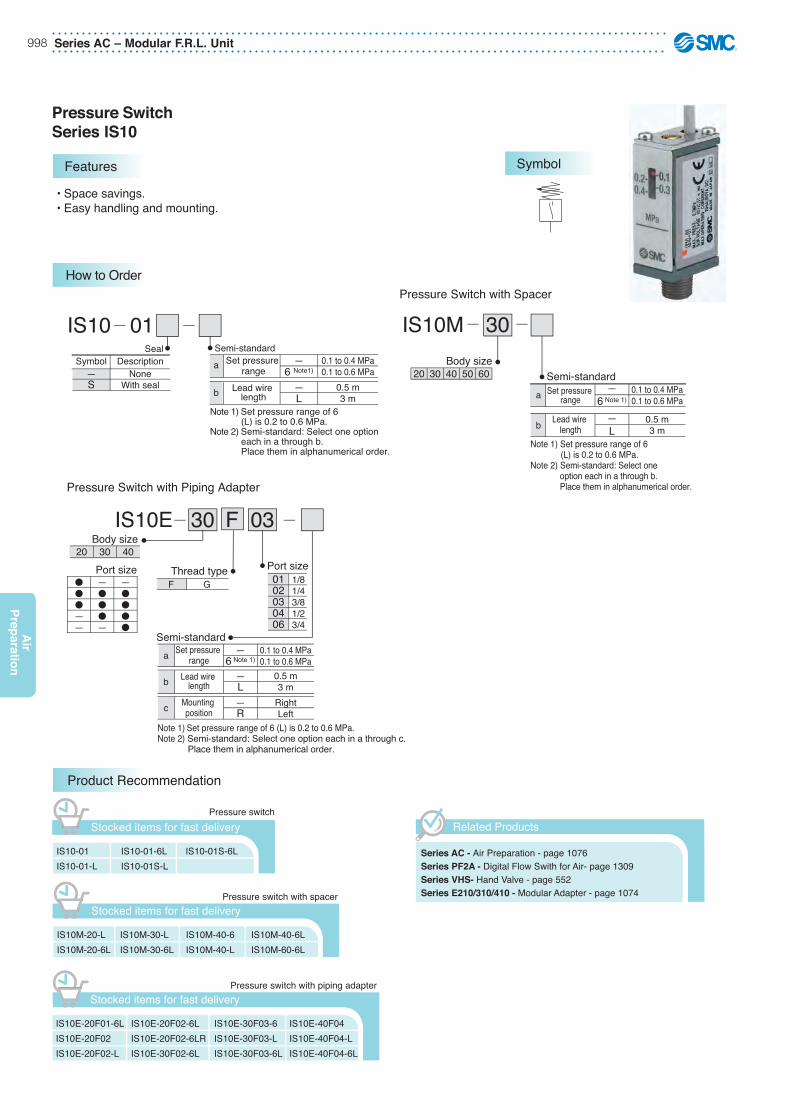
• Space savings.• Easy handling and mounting.
Pressure SwitchSeries IS10
Features
How to Order
Symbol
IS10 01DescriptionSymbol
—S
Seal—
6 Note1)Set pressure
range—L
Lead wire length
NoneWith seal
0.1 to 0.4 MPa0.1 to 0.6 MPa
0.5 m3 m
Semi-standard
Note 1) Set pressure range of 6 (L) is 0.2 to 0.6 MPa.Note 2) Semi-standard: Select one option each in a through b. Place them in alphanumerical order.
30Pressure Switch with Spacer
IS10E 30 03Pressure Switch with Piping Adapter
IS10M
Note 1) Set pressure range of 6 (L) is 0.2 to 0.6 MPa.Note 2) Semi-standard: Select one option each in a through c. Place them in alphanumerical order.
0.1 to 0.4 MPa0.1 to 0.6 MPa
—6 Note 1)
—L
Set pressure range
Lead wire length
0.5 m3 m
30 4020 50 60Body size
a
c
b
0.1 to 0.4 MPa0.1 to 0.6 MPa
1/81/43/81/23/4
RightLeft
—6 Note 1)
0102030406
—R
—L
Set pressure range
Port size
Mounting position
Lead wire length
0.5 m3 m
���——
30 4020
—���—
—����
Body size
Note 1) Set pressure range of 6 (L) is 0.2 to 0.6 MPa.Note 2) Semi-standard: Select one option each in a through b. Place them in alphanumerical order.
Semi-standard
Semi-standard
Port sizeGF
Thread type
IS10-01IS10-01-L
IS10-01-6LIS10-01S-L
Product Recommendation
Stocked items for fast delivery
Series AC - Air Preparation - page 1076Series PF2A - Digital Flow Swith for Air- page 1309 Series VHS- Hand Valve - page 552Series E210/310/410 - Modular Adapter - page 1074
Related Products
IS10-01S-6L
IS10M-20-LIS10M-20-6L
IS10M-30-LIS10M-30-6L
Stocked items for fast delivery
IS10M-40-6IS10M-40-L
IS10M-40-6LIS10M-60-6L
IS10E-20F01-6LIS10E-20F02IS10E-20F02-L
IS10E-20F02-6LIS10E-20F02-6LRIS10E-30F02-6L
Stocked items for fast delivery
IS10E-30F03-6IS10E-30F03-LIS10E-30F03-6L
IS10E-40F04IS10E-40F04-LIS10E-40F04-6L
Pressure switch
Pressure switch with spacer
Pressure switch with piping adapter
a
b a
b
F

Modular F.R.L. Unit – Series AC 999
Air
Pre
par
atio
n
For more product options and details see our specifi c catalogues or on-line information.
Specifications
Model IS10-01Air/Inert gas
1.0 MPa0.7 MPa
–5 to 60ºC (No freezing)1a
0.05 MPa or lessFixed 0.08 MPa or less
0.05 MPa or less
Equivalent to IP401/8
62 g
FluidProof pressureMax. operating pressure
Set pressure range
Ambient and fluid temperatureContactsError of scaleHysteresisRepeatability
Wiring specifications
EnclosurePort sizeWeight
AC 2 VA, DC 2 W24 V or less
50 mA48 V
40 mA100 V20 mA
Max. contact capacityVoltage AC/DCMax. operating current and range
Electrical Circuit
Up to 100 V AC/DC
Ree
d sw
itch
ON pressure OFF pressure
0.1 to 0.4 MPaOption: 0.1 to 0.6 MPa
Grommet, Lead wire length: 0.5 mOption: 3 m, 5 m
0.1 0.2 0.3 0.40
0.5
Set pressure scale [MPa]
Ope
ratin
g pr
essu
re [M
Pa]
0.4
0.3
0.2
0.1
Hyste
resis
Switch Characteristics
Set Pressure Range
Part no.
CD-P11CD-P12
Voltage
100 V AC24 V DC
Lead wire length
Switch side: 0.5 mLoad side: 0.5 m
Brown lead wire
Blue lead wire
Choke coilSurge absorber
CD-P11
(+) Brown lead wire
(–) Blue lead wire
Choke coilCapacitor
Resistor
CD-P12
1/8
0.20.4
0.10.3
MPa
(500
0)(3
000)
(500
)
15 23
52
44(2
3)
(13)
Note) When the load which is operated by the pressure switch is an inductive load, or the lead wire is 5 m or longer, use the contact protection box shown in the table below.Otherwise, damage to the switch can result.
• Internal circuit of contact protection box
Dimensions/Construction
Wiring

Series AC – Modular F.R.L. Unit1000
Air
Prep
aration
Accessories
IS10M-20IS10M-30IS10M-40IS10M-50IS10M-60
ModelAC20�AC25�, AC30�AC40�AC40�-06AC50�, AC55�, AC60�
Applicable modelA1113151722
B7485939791
C6471757767
D2830364453
Note) Prepare a spacer separately for modular connection.
Pressure Switch with Spacer
Pressure Switch with Piping Adapter
Pressure switch with piping adapter
Left Right
D
C
B23
(500
0)(3
000)
(500
)
(23)
(13)
Port size
C
B
D
(13)
(23)
(500
0)(3
000)
(500
)
23
Note 1)
Note 2)Note 3)∗
ModelIS10E-20F01IS10E-20F02IS10E-20F03IS10E-30F02IS10E-30F03IS10E-30F04IS10E-40F02IS10E-40F03IS10E-40F04IS10E-40F06
Port sizeG1/8G1/4G3/8G1/4G3/8G1/2G1/4G3/8G1/2G3/4
Applicable model
Note 2)AC40�AR40�, AW40�AWM40, AWD40
A
30
32
32
B
66
73
79
C
55
59
61
D
28
30
37
E
16
13
13
AC20�AR20�, AW20�AWM20, AWD20AC25�, AC30�AR25�, AR30�, AW30�AWM30, AWD30
Pressure switch
LubricatorRegulator
Filter regulator
Air filter
0.20.4
0.10.3
MPa
A
15
0.20.4
0.10.3
MPa
A
E
� in the model numbers indicates a thread type. No indication is necessary for Rc; however, indicate N for NPT, and F for G.Cannot be mounted to the AC40�-06 and AW40�-06.Prepare a spacer separately for modular connection.
The pressure switch can be mounted on the AC40�-06 and above and the AW40�-06 by screwing the IS10-01 into the piping adapter E500-�06-X501 or E600-�06-X501 to E600-�10-X501 (Rc1/8 threaded on top surface). Products with a premounted switch are available as a special order. Please contact SMC beforehand.
Modular F.R.L. Unit – Series AC 1001
Air
Pre
par
atio
n
For more product options and details see our specifi c catalogues or on-line information.
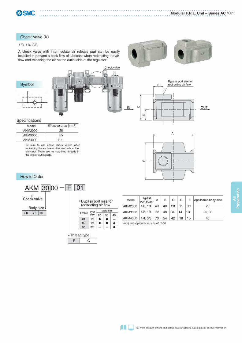
Check valve
ModelAKM2000AKM3000AKM4000
SpecificationsEffective area [mm2] 28 55 111
30 00AKMCheck valve Bypass port size for
redirecting air flow
1/8, 1/4, 3/8A check valve with intermediate air release port can be easily installed to prevent a back flow of lubricant when redirecting the air flow and releasing the air on the outlet side of the regulator.
Be sure to use above check valves when redirecting the air flow on the inlet side of the lubricator. There are no machined threads in the inlet or outlet ports.
Body size
Thread typeF G
IN
Model Bypassport sizes Applicable body sizeA
AKM2000
AKM3000
AKM4000
20
25, 30
40
40B
40C
28D
11E
1153 48 34 14 13
70 54 42 18 15
1/8, 1/41/8, 1/4
1/4, 3/8Note) Not applicable to parts 40 -06.
CD
E
A
B
OUT
Bypass port size forredirecting air flow
20 30 40 Symbol
010203
Portsize1/81/43/8
20
—
30
—
40—
Body size
F
How to Order
Symbol
Check Valve (K)
01
Series AC – Modular F.R.L. Unit1002
Air
Prep
aration
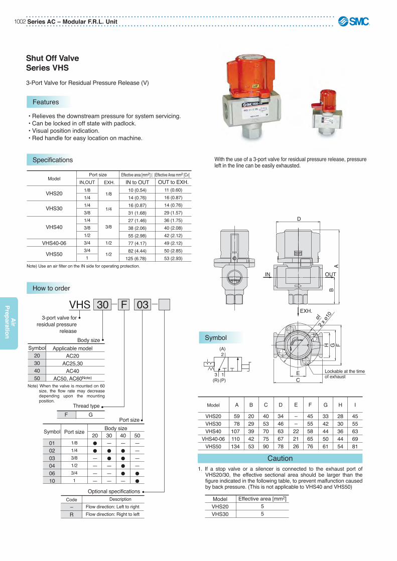
With the use of a 3-port valve for residual pressure release, pressure left in the line can be easily exhausted.
Model
VHS20VHS30VHS40
VHS40-06VHS50
G
3342445061
H
2830364454
I
4555636981
A
5978
107110134
B
2029394253
C
4053707590
D
3446636778
E
––222126
F
4555586576
1. If a stop valve or a silencer is connected to the exhaust port of VHS20/30, the effective sectional area should be larger than the figure indicated in the following table, to prevent malfunction caused by back pressure. (This is not applicable to VHS40 and VHS50)
Caution
Effective area [mm2]55
ModelVHS20VHS30
Model
VHS20
VHS30
VHS40
VHS40-06
VHS50
IN,OUTEffective area [mm2] ( )Effective Area mm2 [Cv]
IN to OUT10 (0.54)14 (0.76)16 (0.87)31 (1.68)27 (1.46)38 (2.06)55 (2.98)77 (4.17)82 (4.44)
125 (6.78)
OUT to EXH.11 (0.60)16 (0.87)14 (0.76)29 (1.57)36 (1.75)40 (2.08)42 (2.12)49 (2.12)50 (2.85)53 (2.93)
Note) Use an air filter on the IN side for operating protection.
EXH.Port size
1/81/41/43/81/43/81/23/43/41
1/8
1/4
3/8
1/2
1/2
(A)2
3(R)
1(P)
Shut Off ValveSeries VHS
• Relieves the downstream pressure for system servicing.• Can be locked in off state with padlock.• Visual position indication.• Red handle for easy location on machine.
Features
Specifications
How to order
SymbolApplicable model
AC20AC25,30
AC40AC50, AC60Note)
VHS3-port valve for
residual pressurerelease
Body size
Thread typeF G
Optional specificationsCode
–R
DescriptionFlow direction: Left to rightFlow direction: Right to left
Symbol20304050
20�
�
————
30—�
�
———
40—�
�
�
�
—
50————�
�
Body sizePort size
Symbol
010203040610
Port size
1/81/43/81/23/41
OUTIN
EXH.øI
2 x ø1
0
F
C
BA
GH
E
D
Lockable at the time of exhaust
SUP
Note)�When the valve is mounted on 60 size, the flow rate may decrease depending upon the mounting position.
3-Port Valve for Residual Pressure Release (V)
30 03F

Modular F.R.L. Unit – Series AC 1003
Air
Pre
par
atio
n
For more product options and details see our specifi c catalogues or on-line information.
Description
Seal
Material
HNBR Note 2)Y100
Y100P-060AS Note 1)Y300
Y300P-060SY200
Y200P-061SY400
Y400P-060SY500
Y500P-060SY600
Y600P-060S
Part no.Replacement parts
Y400T
BC
D
Seal
Centre of F.R.L. body
X
ModelY100Y200Y300Y400Y500
Y600
1020
25, 3040
40-06
50, 55, 60
A63455
6
B27 35.547 57 61
75.5
C15 18.526 31 33
41
D3348596570
86
Applicable body size
A634556
B——
82 96 96120
BB5667————
C 24.529 41 48 48 60
D40.55368
81.586
112
E202435404050
EE 2733————
G 4.5 5.5 7 9 9
11
øG 4.5 5.5 7 9 9
11
ModelY100TY200TY300TY400TY500TY600T
F 6.812 14 18 18 20
J2.83.24 4 4.66.4
K253041505070
H141921262731
JK
D
BB (Y
100T
, Y20
0T o
nly)
BC
H
E
øG
EE (Y
100T
, Y20
0T o
nly)
E
G
F
Centre ofF.R.L. body
X
Description
Seal
Material
HNBR Note 2)Y100T
Y100P-060AS Note 1)Y200T
Y200P-061SY300T
Y300P-060SY400T
Y400P-060SY500T
Y500P-060SY600T
Y600P-060S
Part no.Replacement parts
Seal
Y200T
Y200
RELE
ASE
1
2
RELE
ASE
1
2
Note 1) Y100 comes with 2 O-rings.Note 2) NBR seal is used for Y100 spacer because of no direct contact with fluid.
Note 1) Y100T comes with 2 O-rings.Note 2) NBR seal is used for Y100T spacer because of no direct contact with fluid.
Y400
ASpacer width
X-X
ASpacer width
X-X
X
X
1020
25, 3040
40-06 50, 55, 60
Applicable body size
FRL Spacers and BracketsAccessories
Spacer
Spacer with Bracket
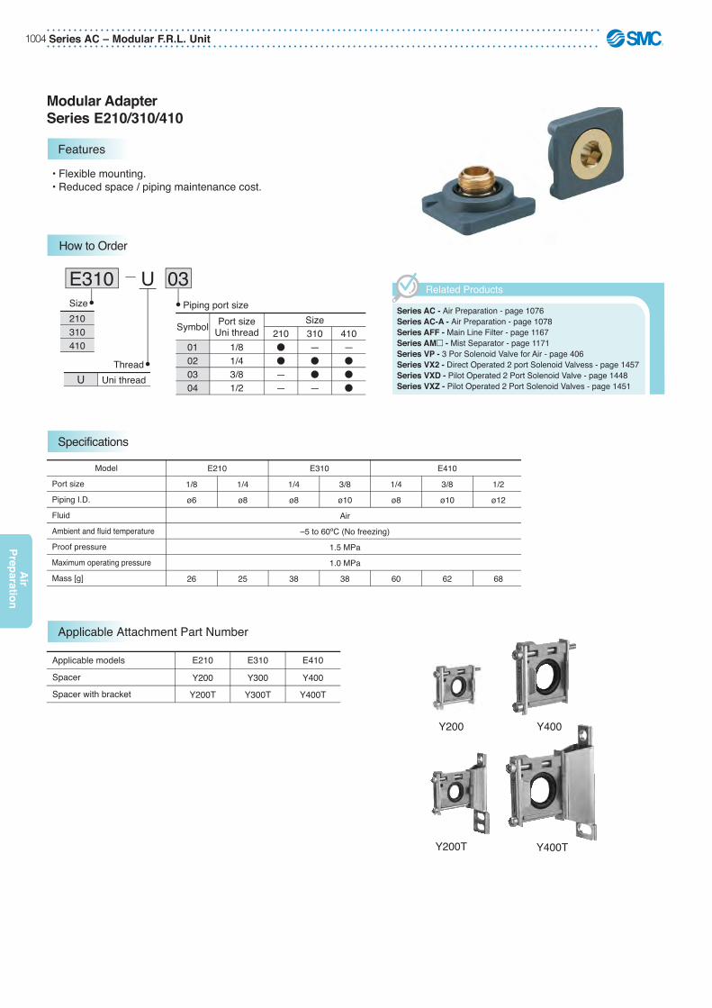
Series AC – Modular F.R.L. Unit1004
Air
Prep
aration
• Flexible mounting.• Reduced space / piping maintenance cost.
Modular AdapterSeries E210/310/410
Features
How to Order
Specifications
USize Piping port size
Symbol
01020304
Port sizeUni thread
1/81/43/81/2
Size310—�
�
—
210�
�
——
410—�
�
�
210310410
ThreadUni threadU
E310 03
Port size
Piping I.D.
Fluid
Ambient and fluid temperature
Proof pressure
Maximum operating pressure
Mass [g]
Model E210 E310 E410
3/8
ø10
Air
–5 to 60ºC (No freezing)
1.5 MPa
1.0 MPa
38
1/8
ø6
26
1/4
ø8
25
1/4
ø8
38
1/4
ø8
60
3/8
ø10
62
1/2
ø12
68
Spacer
Spacer with bracket
Applicable models E210
Y200
Y200T
E310
Y300
Y300T
E410
Y400
Y400T
Y200 Y400
Y400TY200T
Applicable Attachment Part Number
Series AC - Air Preparation - page 1076Series AC-A - Air Preparation - page 1078Series AFF - Main Line Filter - page 1167Series AM� - Mist Separator - page 1171Series VP - 3 Por Solenoid Valve for Air - page 406Series VX2 - Direct Operated 2 port Solenoid Valvess - page 1457Series VXD - Pilot Operated 2 Port Solenoid Valve - page 1448Series VXZ - Pilot Operated 2 Port Solenoid Valves - page 1451
Related Products

Modular F.R.L. Unit – Series AC 1005
Air
Pre
par
atio
n
For more product options and details see our specifi c catalogues or on-line information.
Construction
Unit: [mm]
A
B
Wid
th a
cros
s fla
ts H
TD
Attached product end port
q w
A
Product attached with modular adapter
E210-U01E310-U02, U03E410-U02, U03, U04
E210-U02
No.
12
Replacement parts
O-ringO-ring
Description Material
NBRNBR
E210-U01
E210P-040S—
E210-U02
E210P-030SE210P-050S
Part no.E310-U02E410-U02
E210P-030S—
E310-U03E410-U03
E310P-030S—
E410-U04
E410P-030S—
q Spacer with bracket Y200TY300TY400T
E210-U01 to U02E310-U02 to U03E410-U02 to U04
w Modular adapter A
10.611.111.6
Note) Y200 to Y400 spacers share the same dimensions.
Unit: [mm]
Part no.
E210-U01E210-U02E310-U02E310-U03E410-U02E410-U03E410-U04
1/81/41/43/81/43/81/2
6 8 810 81012
DUni thread
28
30
36
A
21
28
36
B
9
T Width across flatsH
Dimensions Mounting Dimensions
q
w
q

Series AC-A – Modular F.R.L. Unit1006
Air
Prep
aration
AC 30 AF 03 DG
Body size
Model combination
F.R.L. unit
Symbol
–ABCD
AF(1)—(1)(1)—
AR(2)—(2)(3)—
AL(3)(2)———
AW—(1)——(1)
AFW———(2)(2)
Combination
Thread typeF G
Port size
Options Note 1)
Note 1) The number inside ( ) indicates the combination order counted from the inlet side.
40302520
Symbol
0102030406
Portsize
1/81/43/81/23/4
20��———
25—��——
30—��——
40—����
Body size
—
A
B
C
D
20 25 30 40Body size
—C Note 2)
D Note 3)
G Note 4)
M Note 4)
Without auto drain / Without pressure gaugeN.C. (Normal close) Drain port is closed when pressure is not appliedN.O. (Normal open) Drain port is open when pressure is not appliedRound type pressure gauge (with limit indicator)Round type pressure gauge (with colour zone)
Modular F.R.L. UnitSeries AC-A
• Redesigned and renovated.• Energy saving regulator.• In-bowl assembled element construction.• Double layer transparent bowl.• Port sizes: 1/8 to 3/4.• Wide range of attachments and accessories.
Features
How to Order Symbols
(Accessories)Series VHS - Residual Relief 3 Port Valve - page 552Series IS10 - Pressure Switches - page 1093Series AKM - Check Valve - page 1091
(Related Products)Series IDG - Membrane Air Dryer - page 1142Series AV - Soft Start-up Valves - www.smc.euSeries KK - S Couplers - page 1204Series KQ2 - Fittings - page 1184Series TU - Tubing - page 1223
Accessories and Related Products
Product Recommendation
L
21
L
21
L
21
LL
21
LL
21
Note 1) Option G, M are not assembled and supplied loose at the time of shipment.Note 2) When pressure is not applied, condensate which does not start the auto drain
mechanism will be left in the bowl. Releasing the residual condensate before ending operations for the day is recommended.
Note 3) If the compressor is small (0.75 kW, discharge flow is less than 100 L/min[ANR]), air leakage from the drain cock may occur during start of operations. N.C. type is recommended.
Note 4) When the pressure gauge is attached, a 1.0 MPa pressure gauge will be fitted for standard (0.7 MPa) type. 0.4 MPa pressure gauge for 0.2 MPa type.
AC20-F02-AAC20-F02C-AAC20-F02G-AAC30-F03-AAC30-F03D-AAC30-F03G-AAC40-F03-AAC40-F04-AAC40-F04G-AAC40-F06-AAC40-F06G-A
Stocked items for fast delivery
AC20A-F01-AAC20A-F02-AAC20A-F02C-AAC20A-F02CG-AAC20A-F02G-AAC30A-F02-AAC30A-F02D-AAC30A-F03-AAC30A-F03D-AAC30A-F03G-AAC40A-F04D-A
AC40A-F04DG-AAC40A-F04G-AAC40A-F06-AAC40A-F06D-AAC40A-F06G-AAC30B-F03-AAC40B-F04D-AAC40B-F04DG-AAC40B-F04G-AAC40D-F04D-A
* When more than one specification is required, indicate in ascending alphanumeric order.
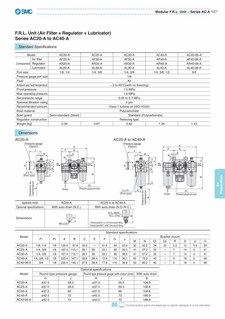
Modular F.R.L. Unit – Series AC-A 1007
Air
Pre
par
atio
n
For more product options and details see our specifi c catalogues or on-line information.
F.R.L. Unit (Air Filter + Regulator + Lubricator)Series AC20-A to AC40-A
Standard Specifications
Dimensions
Air− 5 to 60°C(with no freezing)
1.5 MPa1.0 MPa
0.05 to 0.7 MPa5 μm
Class 1 turbine oil (ISO VG32)Polycarbonate
Relieving type
AC20-A AC25-A AC30-A AC40-A AC40-06-A
1/8, 1/4 1/4, 3/81/8
1/4, 3/8 1/4, 3/8, 1/2
Semi-standard (Steel)
0.39 0.67 1.26 1.43
Standard (Polycarbonate)
AF20-AAR20-AAL20-A
AF30-AAR25-AAL30-A
AF30-AAR30-AAL30-A
AF40-AAR40-AAL40-A
AF40-06-AAR40-06-AAL40-06-A
Model
Component
Port sizePressure gauge port sizeFluidAmbient and fluid temperatureProof pressureMax. operating pressureSet pressure rangeNominal filtration ratingRecommended lubricantBowl materialBowl guardRegulator constructionWeight [kg]
3/4
Air filterRegulatorLubricator
0.82
M5 x 0.8
B
Thread type/Rc, G: ø10 One-touch fittingThread type/NPT: ø3/8" One-touch fitting
BN.C.: GreyN.O.: Black
U
S
R
OUTIN
U
S
R
ANF
BC
IN OUT
P2(Pressure gauge port size)
Pressure gauge(Option)
JJ M
VQ
2Q
1Q
1
2 x P1(Port size)
Cle
aran
ce fo
r m
aint
enan
ceG
ANF
BC
P2(Pressure gauge port size)
E
VQ1
Q1
MJ
J
Pressure gauge(Option)
Cle
aran
ce fo
r m
aint
enan
ceG
2 x P1(Port size)
H H
Drain
Drain
AC20-A AC25-A to AC40-A
ModelOptional specifications
Round type pressure gaugeH
ø37.5ø37.5ø37.5ø42.5ø42.5
J58.558.565 72 72
Hø37.5ø37.5ø37.5ø42.5ø42.5
J59.559.566 72 72
B104.9156.8156.8186.9188.9
Round type pressure gauge (with colour zone) With auto drain
AC20-AAC25-AAC30-AAC40-AAC40-06-A
ModelStandard specifications
Bracket mountP1 P2
1/8, 1/41/4, 3/81/4, 3/8
1/4, 3/8, 1/23/4
1/81/81/81/81/8
A
126.4167.4167.4220.4235.4
B
87.6115.1115.1147.1149.1
C
35.938.138.139.837.8
E
—30 30 38.438.4
F
41.655.155.172.677.6
G
60 80 80110110
J
23.430.530.536.139.6
M3041415050
N43.257.257.275.280.2
Q1
2435354040
Q2
33————
R5.57 7 9 9
S1214141818
U3.54 4 5 5
V2941414848
AC20-AAC25-AAC30-AAC40-AAC40-06-A
With auto drain (N.O./N.C.)With auto drain (N.C.)Optional specifications
Dimensions
Applicable model AC20-A AC25-A to AC40-A
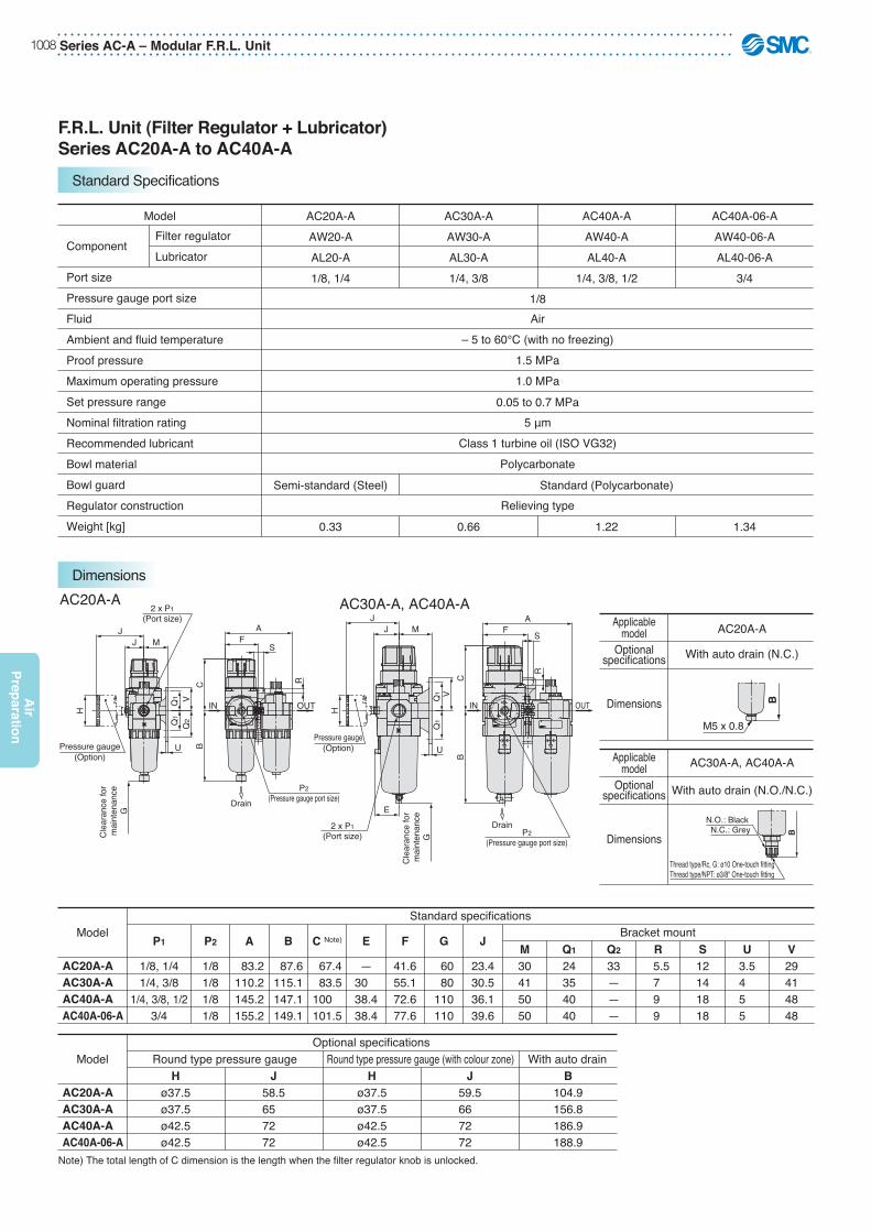
Series AC-A – Modular F.R.L. Unit1008
Air
Prep
aration
F.R.L. Unit (Filter Regulator + Lubricator)Series AC20A-A to AC40A-A
Standard Specifications
Dimensions
With auto drain (N.C.)Optionalspecifications
Dimensions
Applicablemodel AC20A-A
With auto drain (N.O./N.C.)Optionalspecifications
Dimensions
Applicablemodel AC30A-A, AC40A-A
Air– 5 to 60°C (with no freezing)
1.5 MPa1.0 MPa
5 μmClass 1 turbine oil (ISO VG32)
Polycarbonate
Relieving typeSemi-standard (Steel)
0.33
Standard (Polycarbonate)
0.05 to 0.7 MPa
0.66 1.22 1.34
Model
Component
Port sizePressure gauge port sizeFluidAmbient and fluid temperatureProof pressureMaximum operating pressureSet pressure rangeNominal filtration ratingRecommended lubricantBowl materialBowl guardRegulator constructionWeight [kg]
Filter regulatorLubricator
1/8
AC40A-06-AAW40-06-AAL40-06-A
3/4
AC40A-AAW40-AAL40-A
1/4, 3/8, 1/2
AC30A-AAW30-AAL30-A1/4, 3/8
AC20A-AAW20-AAL20-A1/8, 1/4
U
R
S
U
Cle
aran
ce fo
r m
aint
enan
ceG
S
R
OUTIN
AF
P2(Pressure gauge port size)
BC
IN OUT
Pressure gauge(Option)
JMJ
2 x P1(Port size)
VQ
2Q1
Q1
Cle
aran
ce fo
r m
aint
enan
ceG
H
BC
FA
P2(Pressure gauge port size)
Pressure gauge(Option)
JJ M
VQ1
Q1
2 x P1(Port size)
E
H
M5 x 0.8
B
Thread type/Rc, G: ø10 One-touch fittingThread type/NPT: ø3/8" One-touch fitting
BN.C.: GreyN.O.: Black
Drain
Drain
AC20A-A AC30A-A, AC40A-A
Note) The total length of C dimension is the length when the filter regulator knob is unlocked.
ModelOptional specifications
Round type pressure gaugeH
ø37.5ø37.5ø42.5ø42.5
J58.565 72 72
Hø37.5ø37.5ø42.5ø42.5
J59.566 72 72
B104.9156.8186.9188.9
Round type pressure gauge (with colour zone) With auto drain
AC20A-AAC30A-AAC40A-AAC40A-06-A
ModelStandard specifications
Bracket mountP1 P2
1/8, 1/41/4, 3/8
1/4, 3/8, 1/23/4
1/81/81/81/8
A
83.2110.2145.2155.2
B
87.6115.1147.1149.1
C Note)
67.4 83.5100 101.5
E
—30 38.438.4
F
41.655.172.677.6
G
60 80110110
J
23.430.536.139.6
M30415050
Q1
24354040
Q2
33———
R 5.57 9 9
S12141818
U3.54 5 5
V29414848
AC20A-AAC30A-AAC40A-AAC40A-06-A
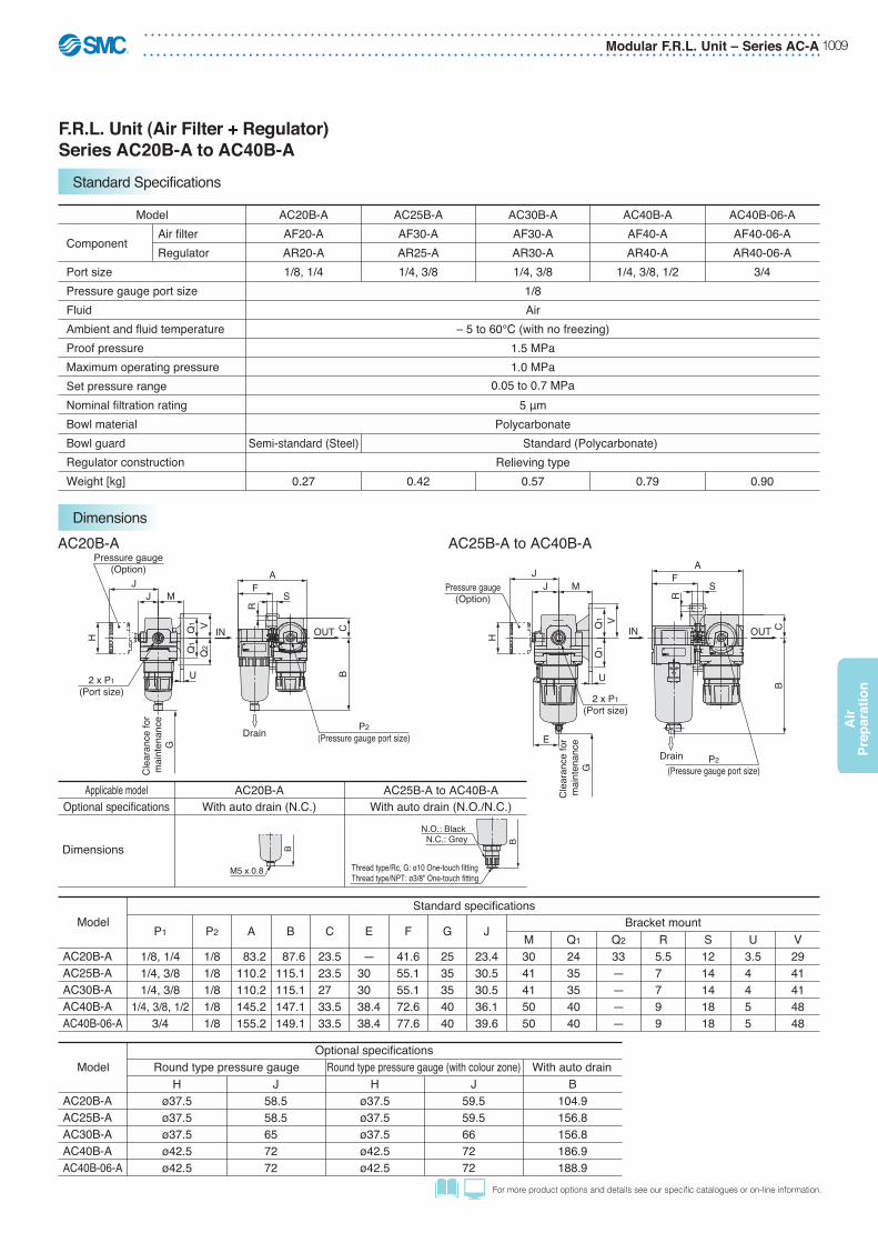
Modular F.R.L. Unit – Series AC-A 1009
Air
Pre
par
atio
n
For more product options and details see our specifi c catalogues or on-line information.
F.R.L. Unit (Air Filter + Regulator)Series AC20B-A to AC40B-A
Standard Specifications
Dimensions
M5 x 0.8
B
Thread type/Rc, G: ø10 One-touch fittingThread type/NPT: ø3/8" One-touch fitting
BN.C.: GreyN.O.: Black
With auto drain (N.O./N.C.)With auto drain (N.C.)Optional specifications
Dimensions
Applicable model AC20B-A AC25B-A to AC40B-A
1/8Air
– 5 to 60°C (with no freezing)1.5 MPa1.0 MPa
5 μmPolycarbonate
Relieving typeSemi-standard (Steel)
0.27
Standard (Polycarbonate)
0.42 0.57 0.79 0.90
Model
Component
Port sizePressure gauge port sizeFluidAmbient and fluid temperatureProof pressureMaximum operating pressureSet pressure rangeNominal filtration ratingBowl materialBowl guardRegulator constructionWeight [kg]
Air filterRegulator
AC25B-AAF30-AAR25-A1/4, 3/8
AC30B-AAF30-AAR30-A1/4, 3/8
AC40B-AAF40-AAR40-A
1/4, 3/8, 1/2
AC40B-06-AAF40-06-AAR40-06-A
3/4
AC20B-AAF20-AAR20-A1/8, 1/4
0.05 to 0.7 MPa
U
R
S
OUTINH
UR
S
OUT
AF
BC
P2(Pressure gauge port size)
Q2
VQ1
Q1
MJ
J
Pressure gauge(Option)
2 x P1(Port size)
Cle
aran
ce fo
r m
aint
enan
ceG
AF
BC
P2(Pressure gauge port size)
VQ1
Q1
MJ
JPressure gauge(Option)
2 x P1(Port size)
Cle
aran
ce fo
r m
aint
enan
ceG
E
H IN
Drain
Drain
AC20B-A AC25B-A to AC40B-A
ModelOptional specifications
Round type pressure gaugeH
ø37.5ø37.5ø37.5ø42.5ø42.5
J58.558.565 72 72
Hø37.5ø37.5ø37.5ø42.5ø42.5
J59.559.566 72 72
B104.9156.8156.8186.9188.9
Round type pressure gauge (with colour zone) With auto drain
AC20B-AAC25B-AAC30B-AAC40B-AAC40B-06-A
ModelStandard specifications
Bracket mountP1 P2
1/8, 1/41/4, 3/81/4, 3/8
1/4, 3/8, 1/23/4
1/81/81/81/81/8
A
83.2110.2110.2145.2155.2
B
87.6115.1115.1147.1149.1
C
23.523.527 33.533.5
E
—30 30 38.438.4
F
41.655.155.172.677.6
G
2535354040
J
23.430.530.536.139.6
M3041415050
Q1
2435354040
Q2
33————
R5.57 7 9 9
S1214141818
U3.54 4 5 5
V2941414848
AC20B-AAC25B-AAC30B-AAC40B-AAC40B-06-A

Series AC-A – Modular F.R.L. Unit1010
Air
Prep
aration
F.R.L. Unit (Air Filter + Mist Separator + Regulator)Series AC20C-A to AC40C-A
Standard Specifications
Dimensions
With auto drain (N.C.)Optionalspecifications
Dimensions
Applicablemodel AC20C-A
With auto drain (N.O./N.C.)Optionalspecifications
Dimensions
Applicablemodel AC30C-A, AC40C-A
M5 x 0.8
B
Thread type/Rc, G: ø10 One-touch fittingThread type/NPT: ø3/8" One-touch fitting
BN.C.: GreyN.O.: Black
AC20C-A AC30C-A, AC40C-A
1/8Air
– 5 to 60°C (with no freezing)1.5 MPa1.0 MPa0.05 MPa
0.05 to 0.7 MPaAF: 5 μm, AFM: 0.3 μm (99.9% filtered particle size)
MAX 1.0 mg/m3 (ANR) (≈0.8 ppm) Note 2) Note 3)
Polycarbonate
Relieving type
450
0.67
200
Semi-standard (Steel)
0.38
Standard (Polycarbonate)
450
0.82
1100
1.26
1100
1.42
Model
Component
Port sizePressure gauge port sizeFluidAmbient and fluid temperatureProof pressureMaximum operating pressureMinimum operating pressureSet pressure rangeNominal filtration ratingOutlet side oil mist concentrationRated flow [l/min (ANR)] Note 1)
Bowl materialBowl guardRegulator constructionWeight [kg]
Air filterMist separatorRegulator
AC40C-06-AAF40-06-A
AFM40-06-AAR40-06-A
3/4
AC40C-AAF40-A
AFM40-AAR40-A
1/4, 3/8, 1/2
AC30C-AAF30-A
AFM30-AAR30-A1/4, 3/8
AC25C-AAF30-A
AFM30-AAR25-A1/4, 3/8
AC20C-AAF20-A
AFM20-AAR20-A1/8, 1/4
Note 1) Conditions: Mist separator inlet pressure: 0.7 MPa; The rated flow varies depending on the inlet pressure. Keep the air flow within the rated flow to prevent an outflow of lubricant to the outlet side.
Note 2) When the compressor oil mist discharge concentration is 30 mg/m3 (ANR).Note 3) Bowl O-ring and other O-rings are slightly lubricated.
U
R
S
Drain Drain
OUT
U
S
R
Drain Drain
OUTIN
ANF
IN
BCV
Q2Q1
Q1
MJJ
2 x P1
(Port size)
P2
(Pressure gauge port size)
Cle
aran
ce fo
r m
aint
enan
ceG
Pressure gauge(Option)
ANF
B
P2
(Pressure gauge port size)
JJ M
VQ1
Q1
H
E
Cle
aran
ce fo
r m
aint
enan
ceG
2 x P1
(Port size)
C
Pressure gauge(Option)
H
ModelOptional specifications
Round type pressure gaugeH
ø37.5ø37.5ø37.5ø42.5ø42.5
J58.558.565 72 72
Hø37.5ø37.5ø37.5ø42.5ø42.5
J59.559.566 72 72
B104.9156.8156.8186.9188.9
Round type pressure gauge (with colour zone) With auto drain
AC20C-AAC25C-AAC30C-AAC40C-AAC40C-06-A
ModelStandard specifications
Bracket mountP1 P2
1/8, 1/41/4, 3/81/4, 3/8
1/4, 3/8, 1/23/4
1/81/81/81/81/8
A
126.4167.4167.4220.4235.4
B
87.6115.1115.1147.1149.1
C
23.523.527 33.533.5
E
—30 30 38.438.4
F
41.655.155.172.677.6
G
4050507575
J
23.430.530.536.139.6
M3041415050
N43.257.257.275.280.2
Q1
2435354040
Q2
33————
R5.57 7 9 9
S1214141818
U3.54 4 5 5
V2941414848
AC20C-AAC25C-AAC30C-AAC40C-AAC40C-06-A
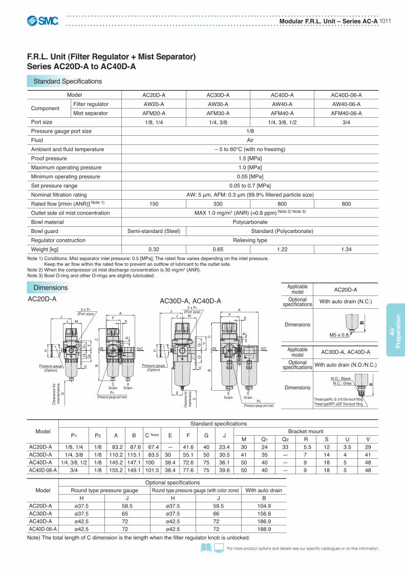
Modular F.R.L. Unit – Series AC-A 1011
Air
Pre
par
atio
n
For more product options and details see our specifi c catalogues or on-line information.
F.R.L. Unit (Filter Regulator + Mist Separator)Series AC20D-A to AC40D-A
Standard Specifications
Dimensions
With auto drain (N.C.)Optionalspecifications
Dimensions
Applicablemodel AC20D-A
With auto drain (N.O./N.C.)Optionalspecifications
Dimensions
Applicablemodel AC30D-A, AC40D-A
M5 x 0.8
B
Thread type/Rc, G: ø10 One-touch fittingThread type/NPT: ø3/8" One-touch fitting
BN.C.: GreyN.O.: Black
AC20D-A AC30D-A, AC40D-A
1/8Air
– 5 to 60°C (with no freezing)1.5 [MPa]1.0 [MPa]0.05 [MPa]
0.05 to 0.7 [MPa]AW: 5 μm, AFM: 0.3 μm (99.9% filtered particle size)
MAX 1.0 mg/m3 (ANR) (≈0.8 ppm) Note 2) Note 3)
Polycarbonate
Relieving type
330
0.65
150
Semi-standard (Steel)
0.32
800
Standard (Polycarbonate)
1.22
800
1.34
Model
Component
Port sizePressure gauge port sizeFluidAmbient and fluid temperatureProof pressureMaximum operating pressureMinimum operating pressureSet pressure rangeNominal filtration ratingRated flow [l/min (ANR)] Note 1)
Outlet side oil mist concentrationBowl materialBowl guardRegulator constructionWeight [kg]
Filter regulatorMist separator
AC40D-06-AAW40-06-AAFM40-06-A
3/4
AC40D-AAW40-AAFM40-A
1/4, 3/8, 1/2
AC30D-AAW30-AAFM30-A1/4, 3/8
AC20D-AAW20-AAFM20-A1/8, 1/4
Note 1) Conditions: Mist separator inlet pressure: 0.5 [MPa]; The rated flow varies depending on the inlet pressure. Keep the air flow within the rated flow to prevent an outflow of lubricant to the outlet side.
Note 2) When the compressor oil mist discharge concentration is 30 mg/m3 (ANR).Note 3) Bowl O-ring and other O-rings are slightly lubricated.
U
S
R
DrainDrain
OUT
U
S
R
DrainDrain
OUTIN
AF
CB
IN
P2(Pressure gauge port size)
Pressure gauge(Option)
JJ M
2 x P1(Port size)
VQ
2
Q1
Q1
H
Cle
aran
ce fo
r m
aint
enan
ceG
AF
CB
JJ M
VQ
1Q
1
Pressure gauge(Option)
P2(Pressure gauge port size)
H
2 x P1(Port size)
E
Cleara
nce f
or ma
inten
ance
G
Note) The total length of C dimension is the length when the filter regulator knob is unlocked.
ModelOptional specifications
Round type pressure gaugeH
ø37.5ø37.5ø42.5ø42.5
J58.565 72 72
Hø37.5ø37.5ø42.5ø42.5
J59.566 72 72
B104.9156.8186.9188.9
Round type pressure gauge (with color zone) With auto drain
AC20D-AAC30D-AAC40D-AAC40D-06-A
ModelStandard specifications
Bracket mountP1 P2
1/8, 1/41/4, 3/8
1/4, 3/8, 1/23/4
1/81/81/81/8
A
83.2110.2145.2155.2
B
87.6115.1147.1149.1
C Note)
67.4 83.5100 101.5
E
—30 38.438.4
F
41.655.172.677.6
G
40507575
J
23.430.536.139.6
M30415050
Q1
24354040
Q2
33———
R 5.57 9 9
S12141818
U3.54 5 5
V29414848
AC20D-AAC30D-AAC40D-AAC40D-06-A

Series AC-A – Modular F.R.L. Unit1012
Air
Prep
aration
• 5 μm filtration degree• Double layer transparent bowl• Good visibility of the condensate• Complete safe bowl guard• Easy and quick in-hand maintenance• Safe and quick bowl locking system• Port sizes: 1/8 to 3/4
Air FilterSeries AF20-A to AF40-A
Features
(Accessories)Series VHS - Residual Relief 3 Port Valve - page 552Series IS10 - Pressure Switches - page 1093Series AKM - Check Valve - page 1091
(Related Products)Series AC - Air Preparation Modular Units - page 1076Series IDG - Membrane Air Dryer - page 1142Series AV - Soft Start-up Valves - www.smc.euSeries KK - S Couplers - page 1204Series KQ2 - Fittings - page 1184Series TU - Tubing - page 1223
Accessories and Related Products
AF20-F01-AAF20-F01C-AAF20-F02-AAF20-F02B-AAF20-F02C-AAF30-F02-AAF30-F02C-AAF30-F02D-AAF30-F03-AAF30-F03C-AAF30-F03D-A
Product Recommendation
Stocked items for fast delivery
AF40-F02-AAF40-F03-AAF40-F03D-AAF40-F04B-AAF40-F04BD-AAF40-F04C-AAF40-F06-AAF40-F06B-AAF40-F06C-AAF40-F06D-A
AF40-AAF20-A
Air Filter Air Filter with Auto Drain
21
L
21
L
Symbol
∗ When more than one specification is required, indicate in ascending alphanumeric order.
0330 BDAF FAccessories
Port size
Body size
Thread type
Air filter
F G
20 30 40
Symbol
0102030406
Portsize1/81/43/81/23/4
20●
●
———
30—●
●
——
40—●
●
●
●
Body size Note 1) A bracket is not assembled and supplied loose at the time of shipment. Including 2 mounting screws.Note 2) When pressure is not applied, condensate which does not start the auto drain mechanism will be left in the bowl. Releasing the residual condensate before ending operations for the day is recommended.Note 3) If the compressor is small (0.75 kW, discharge flow is less than 100 l/min[ANR]), air leakage from the drain cock may occur during start of operations. N.C. type is recommended.
How to Order
20 30 40Body size
—B Note 1)
C Note 2)
D Note 3)
Without mounting option / Without auto drainWith bracketFloat type auto drain (N.C.)Float type auto drain (N.O.)
Note) Drain guide is G1/8(applicable to the AF20-A)and G1/4 (applicable to theAF30-A to AF40-A).
A

Modular F.R.L. Unit – Series AC-A 1013
Air
Pre
par
atio
n
For more product options and details see our specifi c catalogues or on-line information.
Dimensions
Standard specifications
Air–5 to 60°C (with no freezing)
1.5 MPa1.0 MPa
5 μm
Polycarbonate8
Semi-standard (Steel)0.08
25
0.18 0.36 0.41
45
Standard (Polycarbonate)
ModelPort sizeFluidAmbient and fluid temperatureProof pressureMaximum operating pressureNominal filtration ratingDrain capacity [cm3]Bowl materialBowl guardWeight [kg]
AF20-A1/8, 1/4
AF30-A1/4, 3/8
AF40-A1/4, 3/8, 1/2
AF40-06-A3/4
Options/Part No.
AF22P-050ASAD27-A
—
AF32P-050ASAD37-AAD38-A
AD47-AAD48-A
AF42P-050AS AF42P-070ASN.C.N.O.
ModelOptional specifications
Bracket assemblyNote 1)
Float type auto drainNote 2) Note 3)
AF20-A AF30-A AF40-A AF40-06-A
Note 1) Assembly of a bracket and 2 mounting screws.Note 2) Minimum operating pressure: N.O. type–0.1 MPa; N.C. type–0.1 MPa (AD27-A) and 0.15 MPa (AD37-A/47-A).
Please consult with SMC separately for psi and °F unit display specifications.Note 3) Please consult with SMC for details on drain piping to fit NPT or G port sizes.
U
R
S
Drain
OUTIN
U S
R
Drain
TN
B
Cle
aran
ce fo
r m
aint
enan
ceGA
TN
BC
Clea
rance
for
maint
enan
ceG
A
IN OUT
J MD
VQ
Bracket(Option)
E
2 x P (Port size)
V
MD
JBracket(Option)
Q
2 x P (Port size)
M5 x 0.8
B
Thread type/Rc, G: ø10 One-touch fittingThread type/NPT: ø3/8" One-touch fitting
BN.C.: GreyN.O.: Black
C
AF20-A AF30-A to AF40-06-A
Model Standard specifications Optional specifications
P1/8, 1/41/4, 3/8
1/4, 3/8, 1/23/4
A40537075
B 87.6115.1147.1149.1
C 9.814 18 20
D20 26.735.535.5
E—
30 38.438.4
G J20 26.735.535.5
M30415050
N27405454
Q22232625
R 5.4 6.5 8.5 8.5
S 8.48
10.510.5
T40537070
U2.32.32.32.3
V28303534
B104.9156.8186.9188.9
AF20-AAF30-AAF40-AAF40-06-A
Bracket mount With auto drain
25354040
With auto drain (N.O./N.C.)With auto drain (N.C.)Optional specifications
Dimensions
Applicable model AF20-A AF30-A to AF40-06-A
Description
Filter elementBaffleBowl O-ringBowl assembly Note)
Material
Non-woven fabricPBTNBR
Polycarbonate
Part no.AF20-A AF30-A AF40-A AF40-06-A
AF20P-060SAF22P-040SC2SFP-260S
C2SF-A
AF30P-060SAF32P-040SC32FP-260S
C3SF-A
AF40P-060SAF42P-040SC42FP-260S
C4SF-A
Replacement Parts
Note) Bowl O-ring is included. Please contact SMC regarding the bowl assembly supply for psi and °F unit specifications.

Series AC-A – Modular F.R.L. Unit1014
Air
Prep
aration
• Energy saving regulator• Improved pressure drop• Set pressure range 0.05 to 0.7 MPa• Pressure gauge option• Port sizes: 1/8 to 3/4
RegulatorSeries AR20-A to AR40-A
Features
AR20-F01-AAR20-F01B-AAR20-F01BG-AAR20-F01H-AAR20-F02B-AAR20-F02BG-AAR20-F02G-AAR25-F02-AAR25-F02H-A
Product Recommendation
Stocked items for fast delivery
AR25-F03-AAR25-F03H-AAR30-F02-AAR30-F02B-AAR30-F02H-AAR30-F03B-AAR30-F03BG-AAR30-F03G-AAR30-F03H-A
AR40-F02-AAR40-F03-AAR40-F03H-AAR40-F04BG-AAR40-F04G-AAR40-F04H-AAR40-F06-AAR40-F06H-A
AR40-AAR20-A
Regulator
Note 1) Option B, G, H, M are not assembled and supplied loose at the time of shipment.Note 2) Assembly of a bracket and set nuts.Note 3) When the pressure gauge is attached, a 1.0 MPa pressure gauge will be fitted for standard (0.7 MPa) type. 0.4 MPa pressure gauge for 0.2 MPa type.
21
(Accessories)Series VHS - Residual Relief 3 Port Valve - page 552Series IS10 - Pressure Switches - page 1093Series AKM - Check Valve - page 1091
(Related Products)Series AC-A - Air Preparation Modular Units - page 1076Series IDG - Membrane Air Dryer - page 1142Series AV - Soft Start-up Valves - www.smc.euSeries KK - S Couplers - page 1204Series KQ2 - Fittings - page 1184Series TU - Tubing - page 1223
Accessories and Related Products
Symbol
∗ When more than one specification is required, indicate in ascending alphanumeric order.
AR 30 BGF 03
F G
Body size
Regulator
Thread type
Port size
20��———
25—��——
30—��——
40—����
Body size
20 25 30 40Symbol
0102030406
Portsize1/81/43/81/23/4
How to Order
20 25 30 40Body size
—B Note 2)
H
Without mounting option / Without Pressure gaugeWith bracketWith set nut (for panel fitting)
GM Note 3)
Round type pressure gauge (with limit indicator)Round type pressure gauge (with colour zone)
Accessories Note 1)
A
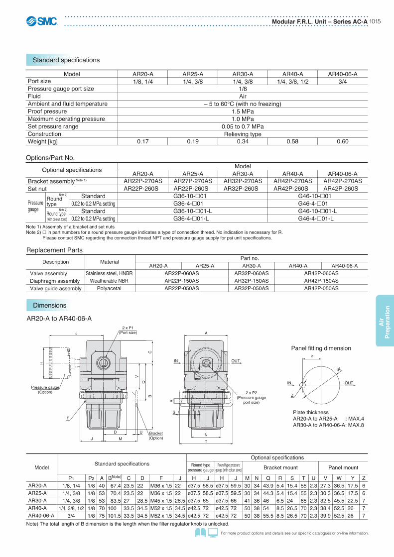
Modular F.R.L. Unit – Series AC-A 1015
Air
Pre
par
atio
n
For more product options and details see our specifi c catalogues or on-line information.
Dimensions
Standard specifications
1/8Air
– 5 to 60°C (with no freezing)1.5 MPa1.0 MPa
0.05 to 0.7 MPaRelieving type
ModelPort sizePressure gauge port sizeFluidAmbient and fluid temperatureProof pressureMaximum operating pressureSet pressure rangeConstructionWeight [kg]
AR20-A1/8, 1/4
0.17
AR25-A1/4, 3/8
0.19
AR30-A1/4, 3/8
0.34 0.58 0.60
AR40-A1/4, 3/8, 1/2
AR40-06-A3/4
Options/Part No.
AR22P-270ASAR22P-260S
G36-10-�01G36-4-�01G36-10-�01-LG36-4-�01-L
G46-10-�01G46-4-�01G46-10-�01-LG46-4-�01-L
Standard0.02 to 0.2 MPa setting
Standard0.02 to 0.2 MPa setting
ModelOptional specifications
Bracket assembly Note 1)
Set nut
Pressuregauge
AR20-AAR27P-270ASAR22P-260S
AR25-AAR32P-270ASAR32P-260S
AR30-AAR42P-270ASAR42P-260S
AR40-AAR42P-270ASAR42P-260S
AR40-06-A
Note 1) Assembly of a bracket and set nutsNote 2) � in part numbers for a round pressure gauge indicates a type of connection thread. No indication is necessary for R.
Please contact SMC regarding the connection thread NPT and pressure gauge supply for psi unit specifications.
Roundtype
Round type (with colour zone)
Note 2)
Note 2)
Description
Valve assemblyDiaphragm assemblyValve guide assembly
Material
Stainless steel, HNBRWeatherable NBR
Polyacetal
Part no.AR20-A
AR22P-060ASAR22P-150ASAR22P-050AS
AR25-A AR30-AAR32P-060ASAR32P-150ASAR32P-050AS
AR40-AAR42P-060ASAR42P-150ASAR42P-050AS
AR40-06-A
Replacement Parts
Panel fitting dimension
Plate thicknessAR20-A to AR25-A : MAX.4AR30-A to AR40-06-A: MAX.8
U
S
A
OUTIN
R
TN
2 x P2(Pressure gauge
port size)
Pressure gauge(Option)
F
J
H
2 x P1(Port size)
BC
QV
MD
JBracket(Option)
Y
W
IN OUT
Z
AR20-A to AR40-06-A
Note) The total length of B dimension is the length when the filter regulator knob is unlocked.
Model Standard specificationsOptional specifications
P1
1/8, 1/41/4, 3/81/4, 3/8
1/4, 3/8, 1/23/4
P2
1/81/81/81/81/8
A4053537075
BNote)
67.4 70.4 83.5100 101.5
C23.523.527 33.533.5
D22 22 28.534.534.5
FM36 x 1.5M36 x 1.5M45 x 1.5M52 x 1.5M52 x 1.5
J22 22 28.534.534.5
J58.558.565 72 72
J59.559.566 72 72
H Hø37.5ø37.5ø37.5ø42.5ø42.5
ø37.5ø37.5ø37.5ø42.5ø42.5
M3030415050
N3434363838
Q43.944.346 54 55.5
R5.45.46.58.58.5
S15.415.424 26.526.5
U2.32.32.32.32.3
V27.330.332.538.439.9
W36.536.545.552.552.5
Y17.517.522.526 26
Z66777
AR20-AAR25-AAR30-AAR40-AAR40-06-A
Bracket mount Panel mountRound typepressure gauge
Round type pressuregauge (with colour zone)
T5555657070

Series AC-A – Modular F.R.L. Unit1016
Air
Prep
aration
• For ISO VG32 Oil• Double layer transparent bowl• Complete safe bowl guard• Safe and quick bowl locking system• Port sizes: 1/8 to 3/4
LubricatorSeries AL20-A to AL40-A
Features
(Accessories)Series VHS - Residual Relief 3 Port Valve - page 552Series IS10 - Pressure Switches - page 1093Series AKM - Check Valve - page 1091
(Related Products)Series AC-A - Air Preparation Modular Units - page 1076Series IDG - Membrane Air Dryer - page 1142Series AV - Soft Start-up Valves - www.smc.euSeries KK - S Couplers - page 1204Series KQ2 - Fittings - page 1184Series TU - Tubing - page 1223
Accessories and Related Products
AL20-F01-AAL20-F02-AAL30-F02-AAL40-F02-A
Product Recommendation
Stocked items for fast delivery
AL40-F03-AAL40-F04B-AAL40-F06-A
AL40-AAL20-A
Lubricator
Symbol
Thread type
AL 30 03F
F G
Lubricator
Body sizePort size
20 30 40 20
———
30—
——
40—
Body sizeSymbol
0102030406
Portsize1/81/43/81/23/4
How to Order
20 30 40Body size
—B Note 1)
Without mounting optionWith bracket
Accessories
F A
Note 1) Option B is not assembled and supplied loose at the time of shipment.

Modular F.R.L. Unit – Series AC-A 1017
Air
Pre
par
atio
n
For more product options and details see our specifi c catalogues or on-line information.
Dimensions
Standard specifications
Description
Sight dome assemblyLubrication plug assemblyDamper retainer assembly Damper (assembly)Bowl sealBowl assembly Note)
Material
Polycarbonate——
Synthetic resinNBR
Polycarbonate
Part no.AL20-A AL30-A AL40-A AL40-06-A
AL22P-060ASAL20P-030ASAL20P-040SC2SFP-260S
C2SL-A
AL32P-060ASAL30P-030ASAL30P-040SC32FP-260S
C3SL-A
AL20P-080ASAL42P-060AS
C42FP-260SC4SL-A
AL40P-030ASAL40P-040S
Replacement Parts
Note) Bowl seal is included. Please contact SMC regarding the bowl assembly supply for psi and °F unit specifications.
U
R
S
OUTIN
U
R
S
OUTIN
TN
CB
A
Cle
aran
ce fo
rm
aint
enan
ceG
J MD
Bracket(Option)
Q
2 x P (Port size)
TN
CB
A
MJD
Bracket(Option)
Q
E
2 x P (Port size)
Cle
aran
ce fo
rm
aint
enan
ceG
AL30-A, AL40-AAL20-A
Model Standard specifications Optional specifications
P1/8, 1/41/4, 3/8
1/4, 3/8, 1/23/4
A40537075
B 79.3104.1136.1138.1
C35.938.139.837.8
D20 26.735.535.5
E—
30 38.438.4
G J20 26.735.535.5
M30415050
60 80110110
N27405454
Q22232625
R5.46.58.58.5
S 8.48
10.510.5
T40537070
U2.32.32.32.3
AL20-AAL30-AAL40-AAL40-06-A
Bracket mount
Note) • The flow rate is 5 drops or greater/min under the following conditions: Inlet pressure of 0.5 MPa; Class 1 turbine oil (ISO VG32); Temperature at 20°C; Oil adjustment valve fully opened.
• Use air consumption flow rate for minimum dripping flow rate.
Air1.5 MPa1.0 MPa
– 5 to 60°C (with no freezing)
Class 1 turbine oil (ISO VG32)Polycarbonate
15
25
Semi-standard (Steel)0.10
55
0.20
1/4: 303/8: 40
0.38
1/4: 303/8: 401/2: 50
50
0.43Standard (Polycarbonate)
135
ModelPort sizeFluidProof pressureMaximum operating pressureAmbient and fluid temperature
Minimum dripping flow rate[L/min (ANR)] Note)
Oil capacity [cm3]Recommended lubricant Bowl materialBowl guardWeight [kg]
AL20-A1/8, 1/4
AL30-A1/4, 3/8
AL40-A1/4, 3/8, 1/2
AL40-06-A3/4
Note) Assembly of a bracket and 2 mounting screws.AF22P-050AS AF32P-050AS AF42P-050AS AF42P-070AS
ModelOptional specifications
Bracket assembly Note)AL20-A AL30-A AL40-A AL40-06-A
Option/Part No.
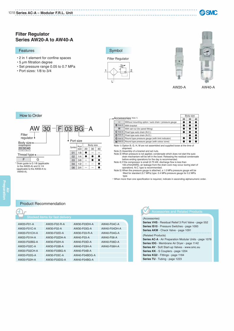
Series AC-A – Modular F.R.L. Unit1018
Air
Prep
aration
• 2 in 1 element for confine spaces• 5 μm filtration degree• Set pressure range 0.05 to 0.7 MPa• Port sizes: 1/8 to 3/4
Filter RegulatorSeries AW20-A to AW40-A
Features
AW20-F01-AAW20-F01C-AAW20-F01CH-AAW20-F01H-AAW20-F02BG-AAW20-F02C-AAW20-F02CH-AAW20-F02G-AAW20-F02H-A
Product Recommendation
Stocked items for fast delivery
AW20-F02-R-AAW30-F02-AAW30-F02D-AAW30-F02DH-AAW30-F02H-AAW30-F03B-AAW30-F03BG-AAW30-F03C-AAW30-F03DG-A
AW30-F03DH-AAW30-F03G-AAW30-F03-R-AAW40-F03-AAW40-F03D-AAW40-F03H-AAW40-F04B-AAW40-F04BDG-AAW40-F04BG-A
AW40-F04C-AAW40-F04DH-AAW40-F04G-AAW40-F06-AAW40-F06D-AAW40-F06H-A
AW40-AAW20-A
Filter Regulator
L
1 2
(Accessories)Series VHS - Residual Relief 3 Port Valve - page 552Series IS10 - Pressure Switches - page 1093Series AKM - Check Valve - page 1091
(Related Products)Series AC-A - Air Preparation Modular Units - page 1076Series IDG - Membrane Air Dryer - page 1142Series AV - Soft Start-up Valves - www.smc.euSeries KK - S Couplers - page 1204Series KQ2 - Fittings - page 1184Series TU - Tubing - page 1223
Accessories and Related Products
03 BG30AW F
Accessories Note 1)
Thread typeG
Port sizeBody size
Filterregulator
20 30 40 20��———
30—��——
40—����
Body sizeSymbol
0102030406
Portsize1/81/43/81/23/4
F
How to Order20 30 40
—B Note 2)
HC Note 3)
D Note 4)
G Note 5)
M Note 5)
Float type auto drain (N.C.)Float type auto drain (N.O.)Round type pressure gauge (with limit indicator)Round type pressure gauge (with colour zone)
Without mounting option / auto drain / pressure gaugeWith bracketWith set nut (for panel fitting)
Body size
* When more than one specification is required, indicate in ascending alphanumeric order.
Note 1) Option B, G, H, M are not assembled and supplied loose at the time of shipment.Note 2) Assembly of a bracket and set nuts.Note 3) When pressure is not applied, condensate which does not start the auto drain mechanism will be left in the bowl. Releasing the residual condensate before ending operations for the day is recommended.Note 4) If the compressor is small (0.75 kW, discharge flow is less than 100 l/min[ANR]), air leakage from the drain cock may occur during start of operations. N.C. type is recommended.Note 5) When the pressure gauge is attached, a 1.0 MPa pressure gauge will be fitted for standard (0.7 MPa) type. 0.4 MPa pressure gauge for 0.2 MPa type.
* Drain guide is G 1/8 (applicable to the AW20-A) and G 1/4 (applicable to the AW30-A to AW40-A).
A
Symbol

Modular F.R.L. Unit – Series AC-A 1019
Air
Pre
par
atio
n
For more product options and details see our specifi c catalogues or on-line information.
Standard specifications
ModelPort sizePressure gauge port sizeFluidAmbient and fluid temperatureProof pressureMaximum operating pressureSet pressure rangeNominal filtration ratingDrain capacity [cm3]Bowl materialBowl guardConstructionWeight [kg]
AW20-A1/8, 1/4
8
Semi-standard (Steel)
0.21
AW30-A1/4, 3/8
25
0.41 0.75 0.81
AW40-A1/4, 3/8, 1/2
AW40-06-A3/4
45
1/8Air
−5 to 60 ºC (with no freezing)1.5 MPa1.0 MPa
0.05 to 0.7 MPa
Polycarbonate
Relieving type
5 μm
Standard (Polycarbonate)
Options/Part No.ModelOptional specifications
Bracket assembly Note 1)
Set nut
Pressure gauge
Float type auto drain
Round type Note 2) Standard0.02 to 0.2 MPa setting
Standard0.02 to 0.2 MPa setting
N.C.N.O.
Round type Note 2)
(with colour zone)
AR22P-270ASAR22P-260S
AD27-A—
AW20-AAR32P-270ASAR32P-260S
AD37-AAD38-A
AW30-AAR42P-270ASAR42P-260S
AW40-A
G46-10-�01G46-4-�01
G46-10-�01-LG46-4-�01-L
AD47-AAD48-A
G36-10-�01G36-4-�01
G36-10-�01-LG36-4-�01-L
AW40-06-A
Note 1) Assembly of a bracket and set nutsNote 2) � in part numbers for a round pressure gauge indicates a type of connection thread. No indication is necessary for R. Please contact
SMC regarding the connection thread NPT and pressure gauge supply for psi unit specifications.Note 3) Minimum operating pressure: N.O. type−0.1 MPa; N.C. type−0.1 MPa (AD27-A) and 0.15 MPa (AD37-A/47-A).
Please consult with SMC separately for psi and °F unit display specifications.Note 4) Please consult SMC for details on drain piping to fit NPT or G port sizes.
The bowl assembly includes the bowl O-ring.
Note 3) Note 4)
Description
Valve assemblyFilter elementDiaphragm assemblyBowl sealBowl assembly Note)
Material
Stainless steel, HNBRNon-woven fabricWeatherable NBR
NBRPolycarbonate
Part no.AW20-A AW30-A AW40-A AW40-06-A
AW22P-060ASAF20P-060S
AR22P-150ASC2SFP-260S
C2SF-A
AW32P-060ASAF30P-060S
AR32P-150ASC32FP-260S
C3SF-A
AW42P-060ASAF40P-060S
AR42P-150ASC42FP-260S
C4SF-A
Replacement Parts
Note) Bowl seal is included. Please contact SMC regarding the bowl assembly supply for psi and °F unit specifications.
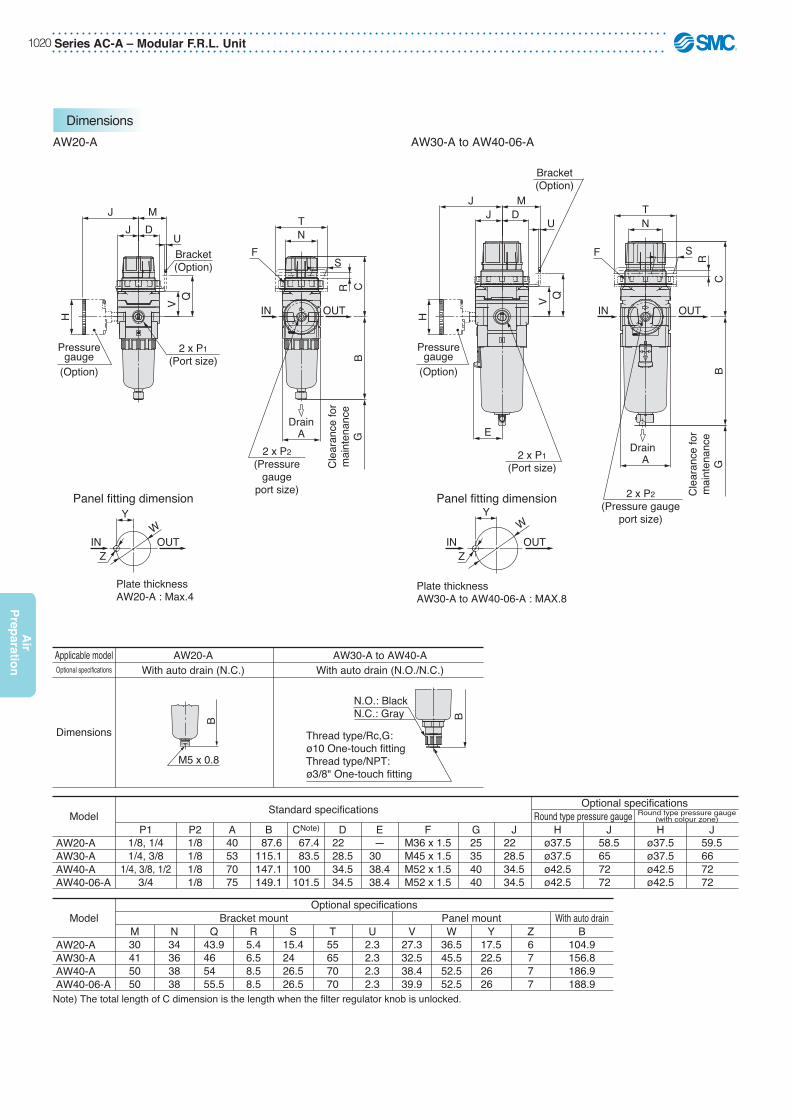
Series AC-A – Modular F.R.L. Unit1020
Air
Prep
aration
Dimensions
U
R
S
Drain
Panel fitting dimension Panel fitting dimension
U
R
S
Drain
TN
CB
F
IN OUT
Cle
aran
ce fo
rm
aint
enan
ceG
Cle
aran
ce fo
rm
aint
enan
ceG
A2 x P2
(Pressuregauge
port size)
Pressuregauge
(Option)
Pressuregauge
(Option)
H
J MDJ
Bracket(Option)
QV
2 x P1(Port size)
TN
F
BC
A
IN OUT
2 x P2(Pressure gauge
port size)
J MDJ
H
QV
Bracket(Option)
2 x P1(Port size)
E
Y
IN OUTW
Z
Y
IN OUTZ
W
Thread type/Rc,G: ø10 One-touch fittingThread type/NPT: ø3/8" One-touch fitting
B
N.O.: BlackN.C.: Gray
AW20-A AW30-A to AW40-06-A
Note) The total length of C dimension is the length when the filter regulator knob is unlocked.
Model Standard specifications Optional specificationsRound type pressure gauge
P1 P2 A B CNote) D E G J1/8, 1/41/4, 3/8
1/4, 3/8, 1/23/4
1/81/81/81/8
40537075
87.6115.1147.1149.1
67.4 83.5100 101.5
22 28.534.534.5
—30 38.438.4
22 28.534.534.5
FM36 x 1.5M45 x 1.5M52 x 1.5M52 x 1.5
25354040
Round type pressure gauge(with colour zone)H
ø37.5ø37.5ø42.5ø42.5
J59.566 72 72
Hø37.5ø37.5ø42.5ø42.5
J58.565 72 72
AW20-AAW30-AAW40-AAW40-06-A
ModelOptional specifications
Bracket mount Panel mount With auto drainM30415050
N34363838
Q43.946 54 55.5
R5.46.58.58.5
S15.424 26.526.5
T55657070
U2.32.32.32.3
V27.332.538.439.9
W36.545.552.552.5
Y17.522.526 26
Z6777
B104.9156.8186.9188.9
AW20-AAW30-AAW40-AAW40-06-A
With auto drain (N.C.) With auto drain (N.O./N.C.)Optional specifications
Dimensions
Applicable model AW20-A AW30-A to AW40-A
M5 x 0.8
B
Plate thicknessAW30-A to AW40-06-A : MAX.8
Plate thicknessAW20-A : Max.4
O S
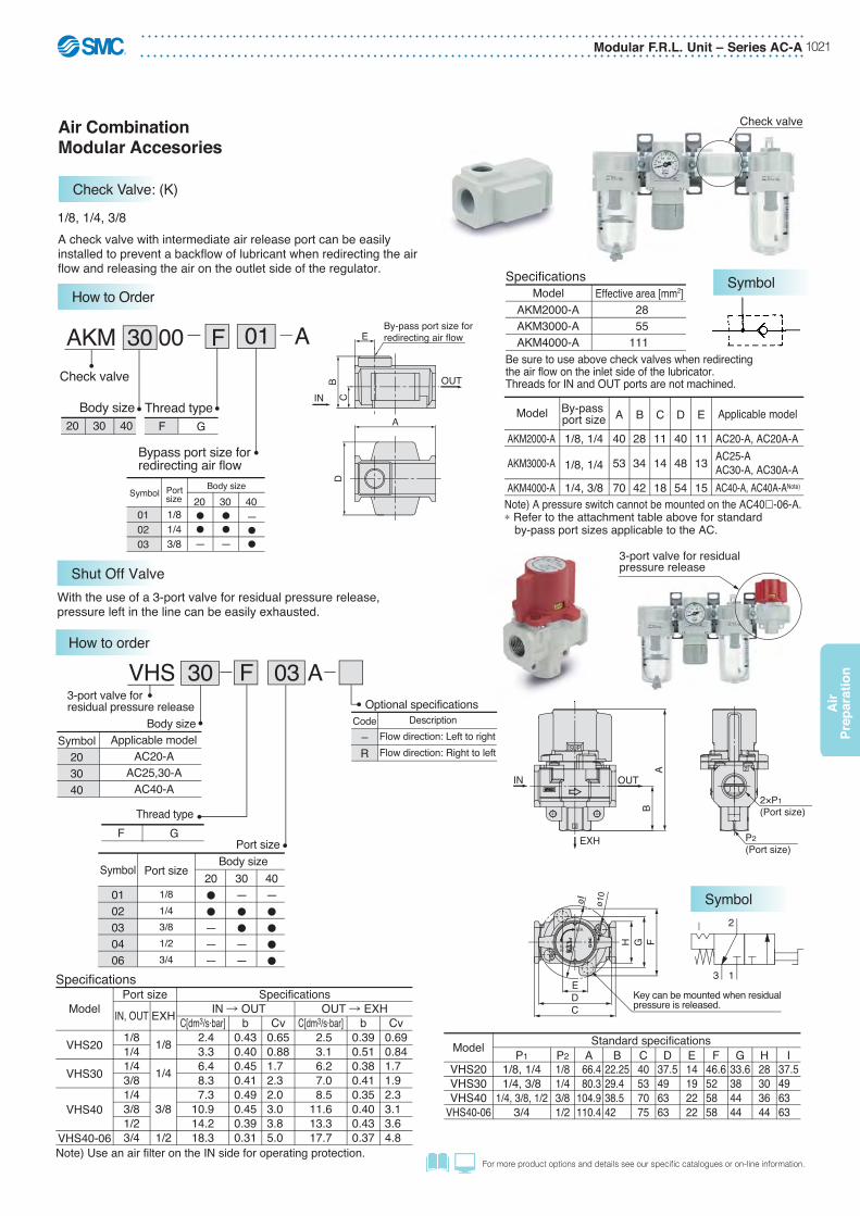
Modular F.R.L. Unit – Series AC-A 1021
Air
Pre
par
atio
n
For more product options and details see our specifi c catalogues or on-line information.
Air CombinationModular Accesories
Check Valve: (K)
Shut Off Valve
AKM2000-A
AKM3000-A
AKM4000-A
By-pass port size1/8, 1/4
1/8, 1/4
1/4, 3/8
AC20-A, AC20A-AAC25-AAC30-A, AC30A-AAC40-A, AC40A-ANote)
A
40
53
70
28
34
42
11
14
18
40
48
54
11
13
15
B C D E
Note) A pressure switch cannot be mounted on the AC40�-06-A.∗ Refer to the attachment table above for standard
by-pass port sizes applicable to the AC.
A
D
Check valve
A check valve with intermediate air release port can be easily installed to prevent a backflow of lubricant when redirecting the air flow and releasing the air on the outlet side of the regulator.
1/8, 1/4, 3/8
AKM2000-AAKM3000-AAKM4000-A
ModelSpecifications
Effective area [mm2] 28 55111
Be sure to use above check valves when redirecting the air flow on the inlet side of the lubricator. Threads for IN and OUT ports are not machined.B
CE
OUT
By-pass port size for redirecting air flow
INApplicable modelModel
3-port valve for residualpressure release
2
øI ø10
EXH
SUP
3
FGH
CDE
AB
IN OUT
P2(Port size)
2×P1(Port size)
EXH.
SUP.
312
Key can be mounted when residual pressure is released.
Note) Use an air filter on the IN side for operating protection.
Specifications
Model
VHS20
VHS30
VHS40
VHS40-06
1/81/41/43/81/43/81/23/4
IN, OUT
1/8
1/4
3/8
1/2
EXH IN � OUT OUT � EXHPort size Specifications
C[dm3/s·bar] 2.4 3.3 6.4 8.3 7.310.914.218.3
b0.430.400.450.410.490.450.390.31
Cv0.650.881.7 2.3 2.0 3.0 3.8 5.0
C[dm3/s·bar] 2.5 3.1 6.2 7.0 8.511.613.317.7
b0.390.510.380.410.350.400.430.37
Cv0.690.841.7 1.9 2.3 3.1 3.6 4.8
With the use of a 3-port valve for residual pressure release, pressure left in the line can be easily exhausted.
Model P1 P2 A B C D E F G H I1/8, 1/41/4, 3/8
1/4, 3/8, 1/23/4
1/81/43/81/2
66.4 80.3104.9110.4
22.2529.4 38.5 42
40537075
37.549 63 63
14192222
46.652 58 58
33.638 44 44
28303644
37.549 63 63
VHS20VHS30VHS40
VHS40-06
Standard specifications
3 1
2
A30 00AKMCheck valve
Bypass port size forredirecting air flow
Body size Thread typeF G20 30 40
Symbol
010203
Portsize1/81/43/8
20
—
30
—
40—
Body size
F
How to Order
01
Symbol
Symbol
Applicable modelAC20-A
AC25,30-AAC40-A
30 03FVHS3-port valve forresidual pressure release
Body size
Thread typeF G
Optional specificationsCode
–R
DescriptionFlow direction: Left to rightFlow direction: Right to left
Symbol203040
20�
�
———
30—�
�
——
40—�
�
�
�
Body sizePort size
Symbol
0102030406
Port size
1/81/43/81/23/4
How to order
A

Series AC-A – Modular F.R.L. Unit1022
Air
Prep
aration
Caution in Mounting
Piping Adapter
Cross Spacer
Pipings are possible in all 4 directions.IN/OUT ports are not machined for threads.Please contact SMC if threaded (machined) ports are required.
1/8, 1/4, 3/8, 1/2
Cross spacer
Model Note)
Y24-�01-AY24-�02-AY34-�01-AY34-�02-AY44-�02-AY44-�03-AY54-�03-AY54-�04-A
Port size1/81/41/81/41/43/83/81/2
Applicable model
AC20�-A
AC25�-A, AC30�-A
AC40�-A
AC40�-06-A
E: 4 × RcF: Without thread
A
40
49
60
72
B
40
43
48
62
C
22
28
36
40
D
40
48
54
62
∗ If threaded IN/OUT ports are required, they are available as a special order. Please contact SMC.
∗ Two hexagon socket head plugs are included in the package.
1. When mounting a cross interface directly on the IN side of the lubricator, be sure to use the AKM series check valve between the lubricator and cross interface.
2. Factory mounting of a cross interface on the AC model is available as a special order.
ED
E
E
E
Port size
B C
A
Center of F.R.L. body
F F
Applicable modelPortsize1/81/43/81/43/81/21/43/81/23/4
3/4
A piping adapter allows installation/removal of the component without removing the piping and thus makes maintenance easier.
∗ Separate interfaces are required for modular unit.∗ Factory mounting of a piping adapter on the AC models is available as a
special order.Piping adapter
B
D A
Center of F.R.L. body
Port size
1/8, 1/4, 3/8, 1/2, 3/4 DBA
28
30
36
44
23.5
30
36
40
29.8
31.8
31.8
31.8
Model Note)
E200-�01-AE200-�02-AE200-�03-AE300-�02-AE300-�03-AE300-�04-AE400-�02-AE400-�03-AE400-�04-AE400-�06-A
E500-�06-A
PipPipPiiP iiiiiiingingiing dadadapapt
AC20�-A
AC25�-A, AC30�-A
AC40�-A
AC40�-06-A
Caution in MountingIf a T-shaped spacer is used on the IN side of the lubricator, lubricant may be mixed. Use the AKM series check valve to avoid such possibility.
T-shaped Spacer: (T)
Using a T-shaped facilitates the branching of air flow.1/8, 1/4, 3/8
AC20-A, AC20B-AAC20C-AAC25-A, AC25B-AAC25C-A, AC30-AAC30B-A, AC30C-AAC40-A, AC40B-AAC40C-AAC40-06-A, AC40B-06-AAC40C-06-A
Applicable modelY210-�01-AY210-�02-AY310-�01-AY310-�02-AY410-�02-AY410-�03-AY510-�02-AY510-�03-A
Port size1/81/41/81/41/43/81/43/8
Model Note)
∗ Separate interfaces are required for modular unit.
C
32
38.7
44
46
D
28
30
36
44
E
19
19
24
24
B
41.8
52.7
62
66
A
14.6
14.6
18.6
18.6
T-shaped spacer BC
E
D A
OctagonPort size
Center of F.R.L. body
FF
FF
FF
FF
FF
FF
FF
FF
FF
FF
F
F
FF
F
FF

Modular F.R.L. Unit – Series AC-A 1023
Air
Pre
par
atio
n
For more product options and details see our specifi c catalogues or on-line information.
SpecificationsFluidAmbient and fluid temperatureProof pressureMaximum operating pressureSet pressure range (when OFF)Hysteresis
Air−5 to 60°C (with no freezing)
1.0 MPa0.7 MPa
0.1 to 0.4 MPa0.08 MPa or less
Switch CharacteristicsContact point configurationMaximum contact point capacityOperating voltage: AC, DC
Maximum operating current
1a2 VA (AC), 2 W (DC)
100 V or less12 V to 24 VAC, DC: 50 mA48 VAC, DC: 40 mA100 VAC, DC: 20 mA
Note) For detailed specifications on the IS10 series, please refer to the section of our website IS10 series, www.smc.eu
D
BC
A
15
≈50023
Center of F.R.L. body
A compact integrated pressure switch can be easily installed and facilitates the pressure detection of the line.
Pressure switch
IS10M-20-AIS10M-30-AIS10M-40-AIS10M-50-A
ModelAC20�-AAC25�-A, AC30�-AAC40�-AAC40�-06-A
Applicable modelA10.612.614.616.6
B74.284.593.397.3
C64.470.575.377.3
D28303644
∗ Separate spacers are required for modular unit.
IS10E D
≈500
BC
A23
Center of F.R.L. body
Port size
E
Pressure switch with piping adapter
Left Right
Note 1) � in the model numbers indicates a thread type. No indication is necessary for Rc; however, indicate F for G.
Note 2) Cannot be mounted on the AC40�-06-A.∗ Separate interfaces are required for modular unit.∗ The pressure switch on the AC40�-06-A can be mounted by screwing IS10-01 into the
piping adapter E500-�06-A-X501 (with top-face thread Rc 1/8). Products with a premounted switch are available as a special order. Please contact SMC regarding their availability.
Model Note 1)
IS10E-20�01-AIS10E-20�02-AIS10E-20�03-AIS10E-30�02-AIS10E-30�03-AIS10E-30�04-AIS10E-40�02-AIS10E-40�03-AIS10E-40�04-AIS10E-40�06-A
Port size1/81/43/81/43/81/21/43/81/23/4
Applicable model
Note 2)AC40�-A
A
29.8
31.8
31.8
B
66.3
72.8
78.8
C
55.3
58.8
60.8
D
28
30
37
E
16
13
12.5
AC20�-A
AC25�-A, AC30�-A
Pressure Switch Series IS10
IS10M
How to Order
30Pressure Switch with Spacer
IS10E 30 03Pressure Switch with Piping Adapter
IS10M
Note 1) Set pressure range of 6 (L, Z) is 0.2 to 0.6 MPa.Note 2) Semi-standard: Select one option each in a through c. Place them in alphanumerical order.
0.1 to 0.4 MPa0.1 to 0.6 MPa
—6 Note 1)
—LZ
Set pressure range
Lead wire length
0.5 m3 m5 m
30 4020Body size
a
c
b
0.1 to 0.4 MPa0.1 to 0.6 MPa
1/81/43/81/23/4
RightLeft
—6 Note 1)
0102030406
—R
—LZ
Set pressure range
Port size
Mounting position
Lead wire length
0.5 m3 m5 m
���——
30 4020
—���—
—����
Body size
Note 1) Set pressure range of 6 (L, Z) is 0.2 to 0.6 MPa.Note 2) Semi-standard: Select one option each in a through b. Place them in alphanumerical order.
Semi-standard
Semi-standard
Port size
GFThread type
a
b
F
A
A
Symbol

Series AC-A – Modular F.R.L. Unit1024
Air
Prep
aration
Spacer
Spacer with Bracket
FRL Spacers and BracketsAccesories
Description
Seal
Material
HNBRY200-A
Y220P-050SY300-A
Y320P-050SY400-A
Y420P-050SY500-A
Y520P-050S
Part no.Replacement Parts
Y400T-A
Y200-AY300-AY400-AY500-A
ModelAC20�-AAC25�-A, AC30�-AAC40�-AAC40�-06-A
A3.24.25.25.2
B22.434.242.246.2
C11.217.121.123.1
D44.957.968.575.6
Applicable model
AC20�-AAC25�-A, AC30�-AAC40�-AAC40�-06-A
A3.24.25.25.2
B67829696
C29414848
D53.471.586.189.6
E24354040
EE33———
G 5.57 9 9
Y200T-AY300T-AY400T-AY500T-A
Model F12141818
J3.54 5 5
K30415050
H15.519 26 26
Applicable model
Description
Seal
Material
HNBRY200T-A
Y220P-050SY300T-A
Y320P-050SY400T-A
Y420P-050SY500T-A
Y520P-050S
Part no.Replacement Parts
Y200T-A
Y200-A Y400-A
(Spacer width)
(Spacer width)
X-X
X-X
J
BC
D
X
X
Seal
Center ofF.R.L. body
A
EE
EE(Y
120T
, Y22
0T o
nly)
CB
G
HF
DK
Seal
X
X
Center ofF.R.L. body
A

Precision Regulator – Series IR1000/2000/3000 1025
Air
Pre
par
atio
n
For more product options and details see our specifi c catalogues or on-line information.
Model
Max. supply pressure
Min. supply pressure
Regulating pressure range
Input signal pressureSensitivityRepeatabilityLinearity
Air consumption
Port sizePressure gauge portAmbient and fluid temperatureWeight [kg]
(2)
(1)
(3)
(4)
IR10�0
IR1000: 0.005 to 0.2 MPaIR1010: 0.01 to 0.4 MPaIR1020: 0.01 to 0.8 MPa
1/8
0.14
IR20�0
IR2000: 0.005 to 0.2 MPaIR2010: 0.01 to 0.4 MPaIR2020: 0.01 to 0.8 MPa
1/4
0.30
IR30�0
Set pressure + 0.1 MPa
IR3000: 0.01 to 0.2 MPaIR3010: 0.01 to 0.4 MPaIR3020: 0.01 to 0.8 MPa
11.5 l /min (ANR) or less4.4 l /min (ANR) or less 4.4 l /min (ANR) or less 4.4 l /min (ANR) or less
1/4, 3/8, 1/2 1/8 (2 locations)
0.64
IR2120
Set pressure + 0.05 MPa
0.01 to 0.8 MPa
1/4
0.35
0.01 to 0.8 MPa
IR3120
Set pressure + 0.1 MPa
0.01 to 0.8 MPa
11.5 l /min (ANR) or less
1/4, 3/8, 1/2
0.71
0.01 to 0.8 MPa
Basic type Air operated type
1.0 MPa
Set pressure + 0.05 MPa
Within 0.2% of full spanWithin ±0.5% of full span
Within ±1% of full span
–5 to 60ºC (No freezing)
—
—
Note 1) With the condition of no flow on the output side. Together with the set pressure, be sure to maintain a minimum differential pressure of 0.05 MPa for models IR1000 and IR2000, and 0.1 MPa for model IR3000.Note 2) Applicable only to air operated types IR2120 and IR3120. Note 3) Indicates the linearity of the output pressure with respect to the input signal pressure.Note 4) Air is normally being discharged to the atmosphere from a bleed hole or an exhaust port.
IR1000IR2000IR3000 For series IR1000/2000
IR1000�
IR2000
�
IR3000
�
�
�
ApplicationPrecision regulator
Body size
IR 2
Regulating pressure range
0 0 02
123
0.005 to 0.2 MPa 0.01 to 0.4 MPa0.01 to 0.8 MPa
Note) Air operated type is model IR2120 only.
Note) Air operated type is model IR3120 only.
012
For series IR30000.01 to 0.2 MPa0.01 to 0.4 MPa0.01 to 0.8 MPa
012
Port size
Symbol
01020304
size
1/81/43/81/2
Basic type
Air operated type
0
Handle typeAir pilot (Note)
Adjustment type01
Note) The IR*1*0 type(Air operated) is only availablefor body sizes 2 and 3.
Note) The IR*1*0 type (Air operated)is only available for body sizes 2 and 3.
Precision RegulatorSeries IR1000/2000/3000
• Precise air pressure regulator for instrument applications.• Three body sizes available.• Pressure unaffected by supply pressure or demand changes.• Bracket and pressure gauge can be mounted from 2 directions.• Compact and lightweight.• Superior relief flow characteristics.
Features
IR1000-F01IR1010-F01IR1020-F01
Product Recommendation
Stocked items for fast delivery (Accessories)Series G - Pressure Gauges - www.smc.eu(Related Products)Series AR - Air Regulators - page 1084Series ITV - Electro-pneumatic Regulators - page 1104Series ISE - Digital Pressure Switches - page 1273Series AC - Air Preparation Modular Units - page 1076Series AC-A - Air Preparation Modular Units - page 1076
Accessories and Related Products
How to Order
IR2000-F02IR2010-F02IR2020-F02
IR2120-F02IR3000-F02IR3000-F03
IR3000-F04IR3010-F02IR3010-F03
Symbol
Specifications
IR3010-F04IR3020-F02IR3020-F03
IR3020-F04IR3120-F03IR3120-F04
F
GThread type
F
(At supply pressureof 1.0 MPa)