smartweld : a knowledge-based approach to weldingconceptual design through visualization of a 3d...
TRANSCRIPT

SmartWeld : A Knowledge-based Approach to Welding
J. L. Mitchiner, S. D. Kleban, B. V. Hess, K. W. MahinSandia National Laboratories
Albuquerque, New Mexico 87185-0722jlmitch@ sandia.gov
D. MessinkIntelliCorp
Mountain View, California 94040-2216
AbstractSmartWeld is a concurrent engineering system thatintegrates product design and processing decisions withinan electronic desktop engineering environment. It is beingdeveloped to provide designers, process engineers,researchers and manufacturing technologists withtransparent access to the right process information, processmodels, process experience and process experts, to realize"right the first time" manufacturing. Empiricalunderstanding along with process models are synthesizedwithin a knowledge-based system to identify robustfabrication procedures based on cost, schedule, andperformance. Integration of process simulation tools withdesign tools enables the designer to assess a number ofdesign and process options on the computer rather than onthe manufacturing floor. Task models and generic processmodels are being embedded within user friendly GUrs tomore readily enable the customer to use the SmartWeldsystem and its software tool set without extensive training.The integrated system architecture under developmentprovides interactive communications and sharedapplication capabilities across a variety of workstation andPC-type platforms either locally or at remote sites.
make that legacy information and new science available atthe fingertips of designers, weld engineers, and analysts.
The SmartWeld system supports users from conceptualdesign through final, detailed design by incorporatingmodels of varying fidelity and complexity. Duringconceptual design, it is sufficient for the designer to knowthat acceptable weld processes exist. During final design,the details of the weld schedule are necessary and mayhave to be simulated within a 3D Finite Element Analysiscode to quantify the design margin.
The SmartWeld system addresses two classes of weldingproblems. First, for a few, important Sandia productfamilies we use object models to specify default attributessuch as alternative weld locations, weld function, candidatematerials, part topology, and a finite element mesh that canbe changed parametrically by changing part dimensions.For this class of problem, SmartWeld can assist users fromconceptual design through visualization of a 3D finiteelement analysis of heat dissipation during welding.
Introduction
Welding in the US is a $50]3 per year business whichgenerates upwards of $7B of waste due to rework andscrap. Many of the problems associated with welding arisedue to the high degree of "trial and error" that typicallyaccompanies the development of weld processes andschedules, weld joint designs, and material selection.Sandia material scientists and engineers have decades ofexperience in welding. They have written hundreds ofmemos and papers addressing welding issues frompart/problem specific memos to refereed journal andconference publications. In addition, Sandia analysts havedeveloped weld process models and analysis tools that canpredict thermal response and residual stress due towelding.
This knowledge should be an important contributor towardreducing scrap and rework, however, it was onlyembodied in a select group of experts and was notroutinely integrated into the design of welded assemblies.The goal of the SmartWeld project is to collect andpackage legacy welding information, develop new weldingmodels that advance welding from art to science, and to
Second, users want advice on generic welds, such aswelding a lid to a housing or welding two fiat platestogether. In these cases, the user must provide informationthat is defaulted in the object models of the modeledproduct families. SmartWeld advises on weld jointgeometries, weld process, and weld schedules, but cannotaid in analysis without a user provided mesh.
In the first case, SmartWeld is more useful, but for alimited class of problems. In the second case, SmartWeldprovides less, but to a far broader class of problems. Inboth cases, the goal of SmartWeld is to provide users withthe best available data, information and knowledge toassist them in the design and analysis of weldedassemblies.
SmartWeld can be accessed either directly or through aproduct-focused design environment to provide thewelding perspective. In the standalone mode, a designercan enter SnmrtWeld early in the design conceptualizationstage and rapidly perform "what-if" testing to estimate theimpact of welding on the design. The user can access theweld advisor, the weld schedule database or the weldschedule optimization tools at any time during the designprocess without having to enter the overall SmartWeld
l~tchiner 129
From: Proceedings of the AI and Manufacturing Research Planning Workshop. Copyright © 1996, AAAI (www.aaai.org). All rights reserved.

SmartWeld Environment
.......... ~mLlmm~
/ ". ’~ "’, ~ /l~L’~’mf~m~~-- / ..... . ...........
, .... .,.,. F--’~ m~~
L,,’/ ......: ......: .... .....:: ............’,l ............................¯ \ ~.... u ,,
................. . ..............~ ...........:- .............
/ / / ! i , ,,h "~. ’~.
"~L,~’. ................................. :. ....................... ., ........................... ~ -.
Figure 1. SmartWeld Architecture
architecture. Later, in a more detailed design mode, thedesigner can enter the system through the product designenvironment with many of the design decisions complete.SmartWeld then assists the user in developing a moredetailed design of the weld. It automatically incorporatesthe weld and the joint geometry into the product solidmodel, and creates an executable weld specification.
Weld Design IssuesThe main issues that must be addressed to design apredictably good weld include:
¯ Choosing a weld location. Within product families,usually there are a few locations that are acceptable basedon issues such as, reachability by welding machines andlocation of thermally sensitive regions.
¯ Choosing a weld process and joint design. Differentweld processes and joint designs have different properties,such as, depth of metal penetration, heat input, residualstress, distortion, sensitivity to loading and sensitivity tocorrosive environments. Choosing the weld process andjoint geometry is a core problem. Currently, we areconsidering fusion welds and solid state welds consistingof six arc and beam welding options, six resistance andfriction welding options, and approximately forty weldjoint geometries.
¯ Weld Schedule Development. The details of the weldprocess, and geometry including speed, amps and volts,filler material feedrates, and a full geometric descriptionof the weld joint are are represented in the weld schedule.
¯ Evaluating the effect of welding on productperformance. Welding joins metal by melting the metal ofeach piece and creating a fusion zone which is a compositeof the original materials. The intense heat required forwelding can cause both thermal and mechanical problems.One major concern during welding is damage to thermallysensitive regions near the weld. Changes in the mechanicalproperties of the part in the weld zone due to this heattreatment is a second major concern.
System DesignSmartWeld is being built using a three-tiered client serverarchitecture, see Figure I. All communications betweenthe user interface, the integrating application layer, andeach of the tools are done through CORBATM objects. Thegoal is to create a system that allows teams of developersto work together without interfering with each other. Forexample, the user interface can now be either Motif and X-windows or JavaTM and NetscapeTM. The user interface isindependent of the application layer. We want tonegotiate an interface between the application layerdevelopers and the analysis agent developers that canremain relatively invariant. The analysis agent developerscan then improve and modify their code with no adverseeffects on the application layer developers.
! 30 AI & Manufacturing Workshop
From: Proceedings of the AI and Manufacturing Research Planning Workshop. Copyright © 1996, AAAI (www.aaai.org). All rights reserved.

Figure 2. SmartWeld Graphical User Interface
The system consists of:
¯ A user interface layer - Motif/X-windows orJavarM/NetscapeTM
¯ an intelligent, integrating application layer, whichintegrates, within a single desktop environment, the toolsand information sources needed by the user to makerobust decisions
¯ a Weld Advisor, which captures Sandia weldingknowledge in an object base
¯ a Weld Schedule database that stores the details of weldschedules and joint geometries used successfully in thepast
¯ a Weld Schedule Optimization tool built on MatlabTM
¯ an integrated Pro/EngineerTM for CAD modeling
¯ PATRANTM for meshing
¯ a simple 2D steady state heat flow model (Rosenthal’sequation) that allows users to quickly and analyticallyevaluate temperatures near the weld
¯ new laser weld model for predicting thermal contoursand residual stress using 3D FEA tools
¯ new GTA weld models for predicting thermal contoursand residual stress for multi-pass welds using 3D FEAtools
¯ integrated visualization tools to see the results of the FEAanalyses.
The SmartWeld GUI, shown in Figure 2, has three majorcomponents: The upper section records importantattributes of the current problem solving state. The middlesection is highly structured to guide the user through theweld design and analysis tools required to produce apredictably good weld. The lower section allows expertsdirect access to information and tools, such as the World-Wide-Web, hypertext design guides, CAD tools, MatlabTM,
and finite element analysis tools.
The middle section of the GUI is a network of nodesrepresenting the steps required to design the weld, designthe weld schedule, simulate the temporal temperaturedistribution during the welding process, and visualize thetemperature distribution. This structure allows informationto be passed seamlessly from one step to the next. Thecode in this area is able to both syntactically andsemantically rink all of the weld design and analysis cedes.Each node is color-coded to immediately let the user knowthe status of the current problem - green nodes areavailable for execution; red ones cannot be performedbecause at least one precursor condition is not satisfied;blue ones represent completed tasks.
Mitchiner 131
From: Proceedings of the AI and Manufacturing Research Planning Workshop. Copyright © 1996, AAAI (www.aaai.org). All rights reserved.

Figure 3. Define Part/Weld Window
Using SmartWeld
The first step in the weld design and analysis process is theinitial definition of the part and weld. When the userclicks on it, the window shown in Figure 3 appears. Theuser can either import a design at this point or graphicallychoose a product family by clicking on an icon at the topof the window. In this example the product family has sixdifferent welds. Default dimensions (or dimensions passedfrom the product design environment) are shown on thescreen and can be edited for "what-if’ testing.
The second step in the design and analysis process is theWeld Advisor. The Weld Advisor is an object-orientedknowledge base. Information about the weld location andfunction specified in Define Part/Weld starts the reasoning
required to determine plausible weld scenarios. The weldsare determined to be plausible based on knowledge aboutcompatibility between materials, weld processes and jointgeometries.
The Advisor knows the default attributes of the productfamily when a part of that type is chosen in DefinePart/Weld. The Advisor has both knowledge about weldingin general and specific knowledge pertaining to productfamilies. At this point, it begins to reason in the knowledgebase. During the reasoning process, if information isrequired that is not available to the knowledge base, theuser is queried. When all information requirements aremet, the advisor ranks and scores each plausible weldscenario based on performance criteria.
132 AI & Manufacturing Workshop
From: Proceedings of the AI and Manufacturing Research Planning Workshop. Copyright © 1996, AAAI (www.aaai.org). All rights reserved.
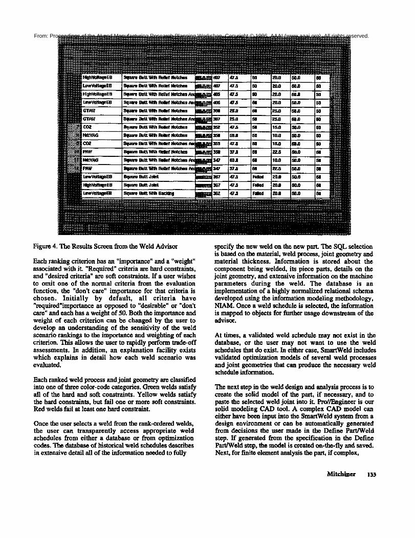
Figure 4. The Results Screen from the Weld Advisor
Each ranking criterion has an "importance" and a "weight"associated with it. "Required" criteria are hard constraints,and "desired criteria" are soft constraints. If a user wishesto omit one of the normal criteria from the evaluationfunction, the "don’t care" importance for that criteria ischosen. Initially by default, all criteria have"required"importance as opposed to "desirable" or "don’tcare" and each has a weight of 50. Both the importance andweight of each criterion can be changed by the user todevelop an understanding of the sensitivity of the weldscenario rankings to the importance and weighting of eachcriterion. This allows the user to rapidly perform trade-offassessments. In addition, an explanation facility existswhich explains in detail how each weld scenario wasevaluated.
Each ranked weld process and joint geometry are classifiedinto one of three color-code categories. Green welds satisfyall of the hard and soft constraints. Yellow welds satisfythe hard constraints, but fail one or more soft constraints.Red welds fail at least one hard constraint.
Once the user selects a weld from the rank-ordered welds,the user can transparently access appropriate weldschedules from either a database or from optimizationcodes. The database of historical weld schedules describesin extensive detail all of the information needed to fully
specify the new weld on the new part. The SQL selectionis based on the material, weld process, joint geometry andmaterial thickness. Information is stored about thecomponent being welded, its piece parts, details on thejoint geometry, and extensive information on the machineparameters during the weld. The database is animplementation of a highly normalized relational schemadeveloped using the information modeling methodology,NIAM. Once a weld schedule is selected, the informationis mapped to objects for further usage downstream of theadvisor.
At times, a validated weld schedule may not exist in thedatabase, or the user may not want to use the weldschedules that do exist. In either case, SmartWeld includesvalidated optimization models of several weld processesand joint geometries that can produce the necessary weldschedule information.
The next step in the weld design and analysis process is tocreate the solid model of the part, if necessary, and topaste the selected weld joint into it. Pro//Engineer is oursolid modeling CAD tool A complex CAD model caneither have been input into the SmartWeld system from adesign environment or can be automatically generatedfrom decisions the user made in the Define Part/Weldstep. If generated from the specification in the DefinePart/Weld step, the model is created on-the-fly and saved.Next, for finite element analysis the part, if complex,
Mitchiner 135
From: Proceedings of the AI and Manufacturing Research Planning Workshop. Copyright © 1996, AAAI (www.aaai.org). All rights reserved.

Figure 5. A meshed cylinder.
should be simplified to minimize meshing and thermalanalysis calculations around features that do not impactthe temperature and stress distributions generated by theweld. The system cannot automatically do thissimplification, but does automatically bring up the modelin Pro/EngineerTM for simplification and then saves it inthe appropriate place.
Next, a finite element mesh must be installed in the solidmodel. PATRANTM is used for mesh generation. Anexample mesh for a cylindrical part is shown in Figure 5.For each product family, an expert analyst designs thefirst parameterized mesh. Once this mesh exists, the usercan modify the mesh parametrically within bounds for"what-if" testing. The user can also specify boundaryconditions. For example, the user can decide to use awater-cooled fixture if heating is expected to cause aproblem. With a water-cooled fixture, the surfacetemperature boundary condition under the fixture can beheld to 30°C for the duration of the weld.
The next step in the weld design and analysis process is tovalidate the selected weld schedule by performing a 3-dimensional thermal analysis. To do this the user mustchoose the appropriate material model, and must specifythe weld process schedule and setup conditions. Fordifferent weld processes, process specific heat fluxmodels are applied. These models are typically
represented as either heating the surface under the arc orbeam or beating the whole volume of metal under the arcor beam. For both material and process models, the mostlikely model is presented as a default, but the user must
134 AI & Manufacturing Workshop
confirm the choice and, if knowledgeable, can override it.
When these conditions are satisfied, the thermal analysisis performed automatically. All of the input to the thermalanalysis code is modified on-the-fly based on the user’sdecisions. The thermal analysis code resides on a severalcomputers on our network so each computer bids and theone with the estimated fastest turnaround is given the job.We are using JACQ, an internally developed Sandia codefor thermal analysis. JACQ simulates the evolution of thetemperatures generated by the welding process over time,including the addition of filler material in the weld.
The final step in the weld design and analysis process isvisualization, as illustrated in Figure 6. The output of thethermal analysis is automatically input into anotherSandia code, FEAVR (Finite Element Analysis Viewer)for automatic creation of a movie of the evolvingtemperature distribution in the part. FEAVR is written inthe Advanced Visual Systems (AVSTM) code. The usercan also pick a node in the mesh and watch thetemperature for that specific point evolve over time. Thisis important if there is a specific thermally sensitive areathat is of concern.
Another component of SmartWeld is random, directaccess to information and tools. Expert users want toexploit the structure of the problem, but do not want to belocked in to that structure. They need random access to allof their tools and information sources. Access to theWorld-Wide-Web, the Weld Advisor, the Weld ScheduleDatabase, and an HTML Weld Design Guide is built intothe system. Pro/EngineerTM, AVSTM, PATRANTM, XVTM,
JACQ, MatlabTM, video-teleconferencing, and applicationsharing are currently available from the Tool Bar.
From: Proceedings of the AI and Manufacturing Research Planning Workshop. Copyright © 1996, AAAI (www.aaai.org). All rights reserved.

Figure 6. Visualization of Weld Temperature Distributionfor a Flat Plate in FEAVR
Additional tools and information sources can be addedeasily.
All of these facilities are completely integrated into apoint-and-click environment that seamlessly translatesfrom one code to the next. The current system runs on adistributed network that links Sandia’s sites in Californiaand New Mexico. The user does not know the syntax ofeach code, the location, or even the machine that isrunning the code. The main code runs on a Sunworkstation in California. The visualization code runs ona different machine in California. The database exists on aSun workstation in New Mexico. All of this is completelytransparent to the user. This distributed system isaccomplished through an agent-based architecture. Thecode is written in C and Kappa, a product of IntelliCorp.
Future WorkUsers of SmartWeld will drive the evolution of the systemuntil it fully meets their requirements for weld design andanalysis. We will to continue to add knowledge to thesystem to improve the recommendations from the WeldAdvisor and to further integrate all of the codes. Our goalis to not only make the integration of these codesmechanically seamless, but semantically seamless as well.
We are also extending the SmartWeld system to newproduct families and customers. As more and moreknowledge is incorporated into the system, the addition ofnew product families should become faster and lessexpensive. We intend to make this system applicable to abroad spectrum of weld processes, product families andcustomers.
SmartWeld is the prototype for the Smartprocessesprogram. We are currently in the initial stages ofdevelopment of a system that addresses a broadercategory of manufacturing processes. Additional newSmartprocesses include encapsulation, forging, soldering,design for machinability and a near net shape advisor.
AcknowledgmentsThe authors acknowledge the valuable contributions ofGregorie Gershanok, Ken Hicken, Gerald Knorovsky,Phil Fuerschbach, Attic Ortega, Jim Lathrop, SteveGianoulakis, Richard Eisler, Charles Ray, Chris Montoya,Kristen Phillips and Larry Schoof to the SmartWeldproject. We also acknowledge Duane Lindner, theProduct Realization Backbone Manager at SandiaNational Laboratories. This work is a component of hisProduct Realization program. This work was performed atSandia National Laboratories supported by the U.S.Department of Energy under contract numbers DE-AC04-76DP00789 and DE-AC04-94AL85000.
Mitchiner 135
From: Proceedings of the AI and Manufacturing Research Planning Workshop. Copyright © 1996, AAAI (www.aaai.org). All rights reserved.