smartweld jet pre-heating torch translation of the
TRANSCRIPT

SMARTWELD JET
PRE-HEATING TORCH
TRANSLATION OF THE ORIGINAL OPERATION MANUAL

SMARTWELD JET TRANSLATION OF THE OPERATION MANUAL
Approved: Engineering Rev. 07/2020-06-30 Page 2 of 38
ENG
LISH
REVISION HISTORY
REVISION DATE REMARKS, SECTION/CHAPTER CONCERNED EDITED BY
01 19.06.2017 Rework, chap. 4/table 5 Engineering
02 15.09.2017 Revision of the content Quality Assurance
03 24.05.2018 Revision of the content chap. 1.3, chap. 1.5, chap. 2.5,
chap. 4, chap. 7.6, chap. 8.2, chap. 10
Measurement technology
04 25.04.2019 Revision of the content chap. 2.1, chap 2.5, chap. 2.6,
chap. 4, chap. 5, chap. 6.2, chap. 7.6, chap. 8, chap. 8.1,
chap. 8.5, chap. 9.2, chap. 10, chap. 11
Measurement technology
05 10.07.2019 Revision of the content chap. 1.3, chap 2.4, chap. 2.5,
chap. 2.11, chap. 3.2, chap. 6.1, chap. 7.2, chap. 7.6,
chap. 10
Measurement technology
06 09.06.2020 Layout adjustment of entire document;
Revision of the content chap. 7.6, chap. 8.2, chap. 10
Measurement technology
07 30.06.2020 Revision of the content: extension to include 110 V
variant
Engineering

SMARTWELD JET TRANSLATION OF THE OPERATION MANUAL
Approved: Engineering Rev. 07/2020-06-30 Page 3 of 38
ENG
LISH

SMARTWELD JET TRANSLATION OF THE OPERATION MANUAL
Approved: Engineering Rev. 07/2020-06-30 Page 4 of 38
ENG
LISH
1 For your information ............................................................................................................... 7
1.1 About this Operation Manual ............................................................................................................. 7
1.2 Using the Operation Manual .............................................................................................................. 7
1.3 Product identification name plate ...................................................................................................... 7
1.4 About the Smartweld Jet pre-heating torch ....................................................................................... 8
1.5 Supporting documents ....................................................................................................................... 8
1.6 Liability................................................................................................................................................ 8
1.7 Copyright protection........................................................................................................................... 8
1.8 Warranty ............................................................................................................................................. 8
1.9 Symbols in this Operation Manual ...................................................................................................... 9
2 Information about your safety .............................................................................................. 10
2.1 Intended Use .................................................................................................................................... 10
2.2 Foreseeable misuse .......................................................................................................................... 10
2.3 Additional provisions ........................................................................................................................ 11
2.4 General sources of danger ................................................................................................................ 11
2.4.1 Risk of injury in the working environment .......................................................................... 11 2.4.2 Risk of burning ..................................................................................................................... 11 2.4.3 Risk of explosion .................................................................................................................. 12 2.4.4 Risk of injury due to electric shock ...................................................................................... 12 2.4.5 Risk of injury due to operational noises .............................................................................. 13 2.4.6 Risk of injury due to falling .................................................................................................. 13 2.4.7 Risk of injury due to lifting heavy objects ............................................................................ 13
2.5 Safety signage ................................................................................................................................... 14
2.6 Emergency stop switch ..................................................................................................................... 15
2.7 Fire protection/fire extinguisher ...................................................................................................... 15
2.8 Conduct during an emergency .......................................................................................................... 16
2.9 Operator obligations ......................................................................................................................... 16
2.10 Qualification of the personnel ........................................................................................................ 16
2.10.1 General ................................................................................................................................ 16 2.10.2 Operating personnel (user) ................................................................................................. 16
2.11 Personal protective equipment ...................................................................................................... 17
3 Structure and function .......................................................................................................... 18
3.1 Functional description ...................................................................................................................... 18

SMARTWELD JET TRANSLATION OF THE OPERATION MANUAL
Approved: Engineering Rev. 07/2020-06-30 Page 5 of 38
ENG
LISH
3.2 Smartweld Jet ................................................................................................................................... 19
3.3 Control unit ....................................................................................................................................... 20
3.4 Pre-heating program......................................................................................................................... 21
3.5 Clamping device flat bottom rail Smartweld Jet ............................................................................... 21
4 Technical data ....................................................................................................................... 22
5 Operating conditions............................................................................................................. 24
6 Transport .............................................................................................................................. 25
6.1 Carrying fixtures on the Smartweld Jet ............................................................................................. 25
6.2 Transporting by hand ........................................................................................................................ 25
6.3 Transporting by crane ....................................................................................................................... 25
6.4 Transporting on the loading area ..................................................................................................... 25
7 Commissioning ...................................................................................................................... 26
7.1 Initial commissioning ........................................................................................................................ 26
7.2 Checks before commissioning .......................................................................................................... 26
7.3 Mounting the clamping device ......................................................................................................... 27
7.4 Preparing the location of welding point ........................................................................................... 27
7.5 Setting up the Smartweld Jet ............................................................................................................ 27
7.6 Establishing the electricity and gas supply ....................................................................................... 28
8 Operation .............................................................................................................................. 31
8.1 Pre-heating the rails and casting system .......................................................................................... 31
8.2 Using the Smartweld Jet via Smartweld Application ........................................................................ 32
8.3 Transferring the Smartweld Jet ........................................................................................................ 32
8.4 Stop Smartweld Jet using the emergency stop switch ..................................................................... 32
8.5 Switch on the Smartweld Jet again after pressing the emergency stop switch ................................ 33
9 Decommissioning .................................................................................................................. 34
9.1 Finishing work at location of welding point ...................................................................................... 34
9.2 Daily decommissioning ..................................................................................................................... 34
10 Troubleshooting .................................................................................................................... 35
11 Maintenance ......................................................................................................................... 37
11.1 Filter maintenance: Cleaning and replacement .............................................................................. 37
11.2 Clean filter ...................................................................................................................................... 37
11.3 Changing the filter .......................................................................................................................... 37

SMARTWELD JET TRANSLATION OF THE OPERATION MANUAL
Approved: Engineering Rev. 07/2020-06-30 Page 6 of 38
ENG
LISH
12 Cleaning/care ........................................................................................................................ 37
13 Spare and wearing parts ....................................................................................................... 38
14 Storage .................................................................................................................................. 38
14.1 Storage conditions .......................................................................................................................... 38
14.2 Recommissioning after extended downtimes ................................................................................ 38
15 Disposal/recycling ................................................................................................................. 38
Publisher:
ELEKTRO-THERMIT GMBH & CO. KG
A GOLDSCHMIDT COMPANY
Chemiestr. 24, 06132 Halle (Saale), Germany
Phone +49 345 7795-600, Fax +49 345 7795-770
[email protected], www.goldschmidt.com.de
Release date: 19.05.2017
Documentation status: 30.06.2020
Photos: Tom Schulze, Ronny Götter FORMAT78 GmbH, actiro Power Blower GmbH,
Elektro-Thermit GmbH & Co. KG, Rasmuss Kaessmann

Approved: Engineering Rev. 07/2020-06-30 Page 7 of 38
SMARTWELD JET TRANSLATION OF THE OPERATION MANUAL
1 For your information
1.1 About this Operation Manual
This Operation Manual contains all the information regarding the intended use of the Smartweld Jet, including the 230 V and 110 V
variants, for trained personnel. Its contents include information about the commissioning, operation, transport and
troubleshooting of the Smartweld Jet pre-heating torch.
The following must be noted:
• The Operation Manual is a component of the pre-heating torch.
• It must always be at the user’s disposal.
• It must always be kept in the vicinity of the Smartweld Jet pre-heating torch throughout its service life.
• It must be handed over when transferring the Smartweld Jet pre-heating torch to other operators and the operator-specific
content supplemented accordingly.
1.2 Using the Operation Manual
The information in this Operation Manual is compulsory. Each user of the Smartweld Jet pre-heating torch must
have fully read and understood the Operation Manual before use. The instructions, prohibitions and commands in
this Operation Manual must always be followed and all safety instructions observed.
1.3 Product identification name plate
A name plate is attached to the bottom of the Smartweld Jet pre-heating torch. The name plate is used for precise product
identification (see Figure 1a, 1b). The operator must ensure that the name plate is replaced if damaged or lost. The information on
the name plate regarding the serial number and year of manufacture must always be quoted in any correspondence with the
manufacturer.
Figure 1a: Example name plate Smartweld Jet, 230 V

Approved: Engineering Rev. 07/2020-06-30 Page 8 of 38
SMARTWELD JET TRANSLATION OF THE OPERATION MANUAL
Figure 1b: Example name plate Smartweld Jet, 110 V
1.4 About the Smartweld Jet pre-heating torch
The Smartweld Jet pre-heating torch (hereinafter only referred to as “Smartweld Jet”) is used to pre-heat and dry rail ends and the
complete casting system for carrying out an aluminothermic welding (see also chapter 2.1 “Intended Use”).
1.5 Supporting documents
The Thermit® code of practice contain important information about how to handle the respective Thermit® welding procedure and
must be observed when working with the Smartweld Jet. The GOK installation and operating instructions for type no. 05 288 501
contains information about operation of the overpressure safety shut-off unit OPSO, SAV. Brief information about this unit is
provided in Chapter 7.6. In addition, the software instructions for Smartweld Application also apply.
1.6 Liability
The user is liable for not observing the Operation Manual. Any warranty is void for damages to the Smartweld Jet or its accessories
or for operational faults, which arise due to non-observance of the Operation Manual or misuse by the user.
Unauthorised modifications or changes to the Smartweld Jet or its accessories are prohibited and thus excluded from the liability.
1.7 Copyright protection
This Operation Manual is protected by the copyright legislation of Elektro-Thermit GmbH & Co. KG. Any duplication of this
document as a whole or in parts and/or transfer to third parties is only permitted with the prior written approval of Elektro-Thermit
GmbH & Co. KG.
1.8 Warranty
The legally prescribed warranty obligation is valid.
Elektro-Thermit GmbH & Co. KG accepts no responsibility and liability and will dismiss any claims against third parties, if personal
injuries or material damages or the like occur covering one or more of the following causes, which can be traced back to the
negligence of the operator or third parties.
• Improper use of the Smartweld Jet,
• failure to observe the information in this Operation Manual,

Approved: Engineering Rev. 07/2020-06-30 Page 9 of 38
SMARTWELD JET TRANSLATION OF THE OPERATION MANUAL
• failure to comply with the specified usages limits and operating conditions,
• improper commissioning, operation, inspection and/or maintenance of the Smartweld Jet,
• modifications on the Smartweld Jet or on individual components, which have not been explicitly approved by Elektro-Thermit
GmbH & Co. KG or
• use of unauthorised accessories or unauthorised spare parts.
1.9 Symbols in this Operation Manual
Pay attention to the symbols shown when using this Operation Manual. Failure to comply may result in the following:
• Risk of injury to personnel,
• Damages to the Smartweld Jet or the surroundings
• Voiding of the warranty or
• The refusal of any liability by the manufacturer.
The following symbols are used in this Operation Manual:
SYMBOL MEANING
DANGER DANGER refers to a hazard with a high degree of risk, which, if not avoided, will lead to death or
severe injuries.
WARNING WARNING refers to a hazard with a medium degree of risk, which, if not avoided, may lead to death
or severe injuries.
CAUTION CAUTION refers to a hazard with a low degree of risk, which, if not avoided, may lead to minor or
moderate injuries.
NOTICE Note, the non-observance of which may result in environmental or material damages.
Attention risk of injury.
General note with reference to helpful tips and supplements.
Read the safety information before using the Smartweld Jet. Non-compliance may lead to injuries and
material damages.
Table 1: Symbols

Approved: Engineering Rev. 07/2020-06-30 Page 10 of 38
SMARTWELD JET TRANSLATION OF THE OPERATION MANUAL
2 Information about your safety
All safety-relevant information can be found in this chapter.
Read through this chapter carefully before using the Smartweld Jet and observe the information during use.
2.1 Intended Use
The Smartweld Jet pre-heating torch is used to pre-heat and dry rail ends and the complete casting system for carrying out an
aluminothermic welding.
The Smartweld Jet may only be operated when taking into account the operating conditions (see chapter 5 “Operating
conditions”).
The Smartweld Jet is technically designed explicitly for its scope of application and may only be exclusively used and operated for
this purpose. Any other use of the Smartweld Jet or its accessories or use that goes beyond its operational boundaries is classed as
improper use.
Elektro-Thermit GmbH & Co. KG is not liable for personal or material damage that has been caused due to improper use of the
Smartweld Jet or its accessories.
Smartweld Jet may only be used by persons who have been trained in the operation of the device and in relevant welding
procedures.
It should be noted that good ventilation must be ensured when using the device indoors.
When using power generators, it is essential to start the generator first and only then to connect the Smartweld Jet.
2.2 Foreseeable misuse
Foreseeable misuse is envisaged when the Smartweld Jet is used for a purpose other than what is specified in chapter 2.1
“Intended Use” and when the operating conditions in chapter 5 “Operating conditions” have not been observed.
Foreseeable misuse includes, among others:
• Use as a heater or heating fan,
• Thawing of frozen objects,
• Use as a flame-thrower,
• Scorching and burning objects.

Approved: Engineering Rev. 07/2020-06-30 Page 11 of 38
SMARTWELD JET TRANSLATION OF THE OPERATION MANUAL
2.3 Additional provisions
In addition to the information in this operation manual, the legal provisions for accident prevention and environmental protection,
as well as the accident prevention provisions of the operator, must be observed.
An “Operator” is a person who operates the Smartweld Jet or its components or allows suitable and trained personnel to operate
on their behalf.
The safety provisions issued by the railway authorities for work on or nearby the track must be observed. Work may only be
commenced once the competent safety officer has granted approval.
2.4 General sources of danger
The following safety information must be observed! The safety information draws attention to the possible personal, material
and environmental damages present and contains information on preventing and addressing dangers.
2.4.1 Risk of injury in the working environment
Welding work takes place in the working environment of a construction site, whereby several welding tasks and other work may be
taking place simultaneously in the immediate vicinity. There is an increased risk of injury, among others, by:
• Being run over by construction vehicles,
• Coming into contact with construction vehicles and other moving work machines,
• Slipping on smooth, wet or oily surfaces,
• Tripping over obstacles,
• Stumbling onto pointed and edged objects,
• Burning from hot surfaces and open flames or
• Hearing damage or loss due to machinery noise.
Observe the following safety measures:
• Comply with all construction site regulations.
• Only work with sufficient lighting.
• Always be cautious and attentive.
2.4.2 Risk of burning
The Smartweld Jet is a machine that may only be operated by authorised personnel. Improper usage can cause severe burns.
Observe the following safety measures:
• Prevent unauthorised personnel from entering the construction site. Coordination must be undertaken by the construction site
management.
• Protect the Smartweld Jet from unauthorised use.
• Never work with the Smartweld Jet in environments susceptible to explosions or fires.
• Always ensure that no flammable or explosive substances can be found in the surroundings of the Smartweld Jet.
• If necessary, clean the working area of combustibles and ensure sufficient ventilation.
• Always wear personal protective equipment (see chapter 2.11 “Personal protective equipment”)

Approved: Engineering Rev. 07/2020-06-30 Page 12 of 38
SMARTWELD JET TRANSLATION OF THE OPERATION MANUAL
Risk of burning when switching on
The gas-air mixture is only ignited approx. 10 seconds after the fan starts up. A jet flame will then result from the nozzle. Non-
recognition of flame ignition may lead to serious burns.
In addition to the points named above, be sure to observe the following precautionary measure especially during commissioning
and operation:
• Once the fan has started up, do not place any body parts (e.g. hands) under the nozzle.
Risk of burning due to hot surfaces
The nozzle heats up to 1,000°C during operation. Contact will result in severe burning.
Pay particular attention to the additional following precautions during commissioning and operation:
• Do not touch the nozzle during and after operation.
• Completely allow the pre-heating program to end and switch on the cooling program if necessary. The program sequence also
contains a predefined period of time for cooling of the torch tube and nozzle.
Burns due to toppling during operation
The Smartweld Jet can topple over if the clamping device is insufficiently secured to the rail. In such an instance, the nozzle can
assume uncontrolled positions with the jet flame and thus cause severe burns.
Pay particular attention to the following precautions during assembly of the clamping device:
• Carry out proper assembly.
• Check the stability of the clamping device and the Smartweld Jet mounted on it before switching on.
Risk of burning due to incorrect pre-heating program
If the incorrect pre-heating program is selected, the casting system may get too hot or be destroyed altogether, causing sparks or
even steel discharge. This can lead to burns.
Pay particular attention to the additional following precautions during commissioning and operation:
• Follow the instructions in this Operation Manual and observe the notes.
• Set the pre-heating program corresponding to the casting system used with the respective Thermit® welding procedure.
• Follow the supporting code of practice (see chapter 1.5 “Supporting documents”).
2.4.3 Risk of explosion
The Smartweld Jet contains gas-bearing components, which may cause explosions if not used properly and thus lead to severe
burns and death.
Observe the following safety measures:
• Do not use the Smartweld Jet during stormy weather.
• Protect the Smartweld Jet and the gas supply in the event of stormy weather.
• Always disconnect the Smartweld Jet from the power and gas supply before maintenance work on the device.
2.4.4 Risk of injury due to electric shock
When working on live components and cables, there is a risk of serious injuries due to electric shock, which can lead to cardiac
fibrillation, cardiac arrest or respiratory failure with fatal consequences.
Observe the following safety measures:
• Only operate the Smartweld Jet in accordance with the specifications of the respective railway company, if a conductor rail is
energized at the place of work.

Approved: Engineering Rev. 07/2020-06-30 Page 13 of 38
SMARTWELD JET TRANSLATION OF THE OPERATION MANUAL
• Never use the Smartweld Jet when the track circuit is under voltage.
• Always ensure that there is no risk of electric shock.
• Always disconnect the Smartweld Jet from the power and gas supply before maintenance work on the device.
2.4.5 Risk of injury due to operational noises
The fan and the nozzle have increased operational noise levels. Extended operational periods may lead to hearing damage and
even permanent hearing loss. The following table shows the maximum allowable operating times determined from sound pressure
measurements. The ambient noise is not taken into consideration.
PROGRAM OPERATING TIME UNTIL LEX,8H = 80 DB(A) OPERATING TIME UNTIL LEX,8H = 85 DB(A)
P1 – Preheating program highest
performance
145 min 460 min
Drying slag pans 20 min 65 min
Cooling modes 480 min 480 min
Table 2: Daily noise exposure values when operating the Smartweld Jet
Observe the following safety measures:
• If necessary, wear hearing protection.
• Only switch on the Smartweld Jet when required.
2.4.6 Risk of injury due to falling
The gas hose and the power cable lay on the ground during use and during transport to the next location of welding point. There is
a risk of injury due to stumbling and falling. Pointed and edged objects may be on the floor.
Observe the following safety measures:
• Place the gas hose and the power cable as such, that there is no risk of stumbling.
• Always wear personal protective equipment (see chapter 2.11 “Personal protective equipment”).
2.4.7 Risk of injury due to lifting heavy objects
The Smartweld Jet has a weight of 23 kg or 28 kg. It must be raised during transport and when placing onto the rail. This can lead to
musculo-skeletal injuries in the case of bad posture.
Pay attention to the following precautions when lifting the Smartweld Jet:
• Use the handles on the Smartweld Jet.
• Adopt a healthy posture.

Approved: Engineering Rev. 07/2020-06-30 Page 14 of 38
SMARTWELD JET TRANSLATION OF THE OPERATION MANUAL
2.5 Safety signage
NOTICE
Keep the safety indications legible! The operator must ensure proper replacement of safety signs if they become damaged
during service life or go missing altogether.
The following safety signs are attached to the Smartweld Jet:
PICTOGRAM MEANING PICTOGRAM MEANING
Observe the operation manual
Wear safety gloves
Wear safety goggles
Wear protective clothing
Wear personal protective equipment
Wear a protective helmet during crane transport
Warning of hot surfaces
Table 3: Safety signage
Figure 2 indicates points where the safety signs are attached.

Approved: Engineering Rev. 07/2020-06-30 Page 15 of 38
SMARTWELD JET TRANSLATION OF THE OPERATION MANUAL
Figure 2: Safety signage
2.6 Emergency stop switch
Triggering the emergency stop switch (see figure 3) causes the electricity and the gas supply to be disconnected immediately.
Operation of the Smartweld Jet is then completely interrupted.
Figure 3: left-hand-image: emergency stop switch, variant 230 V; right-hand-image: emergency stop switch, variant 110 V
The emergency stop switch can be used to stop the Smartweld Jet in an emergency and to turn the device on and off during
operation.
The emergency stop switch must be released after activation so that the Smartweld Jet can be started again. A yellow ring
(230 V) or a green ring (110 V) is visible when released.
2.7 Fire protection/fire extinguisher
The fire safety regulations at the construction site must be observed.
The operator must ensure that there is a functioning CO2 extinguisher in the immediate vicinity of the workplace when working
with the Smartweld Jet.

Approved: Engineering Rev. 07/2020-06-30 Page 16 of 38
SMARTWELD JET TRANSLATION OF THE OPERATION MANUAL
2.8 Conduct during an emergency
In the event of an emergency, immediately switch off the Smartweld Jet using the emergency stop button (see chapter 8.4 “Stop
Smartweld Jet using the emergency stop switch”) and leave the danger zone as quickly as possible.
• In the event of personal injury promptly initiate first aid measures.
• In the event of a fire promptly initiate the necessary fire fighting steps.
2.9 Operator obligations
The operator is the person who operates the Smartweld Jet for commercial or economic purposes themselves or transfers the
use/application to a third party and bears the legal product responsibility for the protection of personnel or third parties.
Obligations of the operator:
• The operator must be aware and implement the valid regulations on work safety and accident prevention.
• The personnel must be informed of the following points when using the Smartweld Jet in the vicinity of conductor rails:
• The necessary safety distances between Smartweld Jet and rail,
• The appropriate safety measures for external energy sources as well as the positioning of the operating personnel.
2.10 Qualification of the personnel
2.10.1 General
Work must only be carried out by qualified personnel!
Only those personnel who fulfil the following requirements may work with the. All other persons are forbidden from using the
Smartweld Jet.
• They have fully read and understood this operation manual.
• They wear the necessary personal protective equipment to ensure safety in the workplace (see chapter 2.11 “Personal
protective equipment”).
• They always observe the safety and accident prevention provisions of the operator and all legal requirements relevant to
personal safety and to the safety of others.
2.10.2 Operating personnel (user)
The operating personnel of the Smartweld Jet, who are permitted to carry out work described in this Operation Manual, are
defined as follows:
• They are continuously trained about technical innovations and possess the necessary fundamental understanding in handling
the Smartweld Jet.
• The following focal points must be emphasised as part of the initial training schedule:
• functional description of the Smartweld Jet,
• explanation of the individual components,
• explanation of the hazard sources,
• use of the Smartweld Jet,
• recognition of functional errors and malfunctions,
• correct cleaning of the Smartweld Jet.

Approved: Engineering Rev. 07/2020-06-30 Page 17 of 38
SMARTWELD JET TRANSLATION OF THE OPERATION MANUAL
2.11 Personal protective equipment
If the operator has added no further provisions, the protective equipment listed in the following table is mandatory when working
with the Smartweld Jet.
SYMBOL PROTECTIVE EQUIPMENT WORK
Protective work clothing
(protective wear for welders in accordance with EN 470-1, if
necessary hi-vis warning clothing in accordance with EN 471)
Transport, commissioning,
operation, decommissioning,
maintenance, cleaning/care
Protective work shoes
(S3 safety shoes in accordance with EN ISO 20345 ankle-height
shoes)
Transport, commissioning,
operation, decommissioning,
maintenance
Protective goggles
(normal and protective level 6 for welding work) Operation (welding)
Protective gloves
(severe mechanical hazards in accordance with EN 388 (4242), EN
402, if necessary protective gloves against thermal risks in
accordance with EN 407)
Transport, commissioning,
operation, decommissioning,
maintenance, cleaning/care
Protective helmet
(industrial safety helmet in accordance with EN 397) Crane transport
Table 4: Personal protective equipment

Approved: Engineering Rev. 07/2020-06-30 Page 18 of 38
SMARTWELD JET TRANSLATION OF THE OPERATION MANUAL
3 Structure and function
The most important components of the Smartweld Jet are illustrated and their function explained in this chapter.
Figure 4: Device components and accessories
(1) Smartweld Jet (5) Gas hose
(2) Nozzle (6) Disconnect coupling
(3) Pressure reducing valve with Euro adapter set (7) Clamping device flat bottom rail Smartweld Jet
(4) Gas leakage shut-off device
More device components:
• Setting gauge (depending on processing conditions)
• Power connection cable Smartweld Jet or
• Power connection cable Smartweld Jet 110 V with Euro power outlet version and USA power outlet version
Optional accessories:
• Transport and storage box
• Twin hose with gas leakage shut-off device and pressure reducing valve
• Clamping device flat bottom rail/grooved rail/crane rail
3.1 Functional description
The Smartweld Jet pre-heating torch is used to pre-heat and dry rail ends and the complete casting system for carrying out an
aluminothermic welding.
Using an external supply and an automatic gas regulator, gas is fed to the Smartweld Jet, which is blended with air in the torch tube
by a high performance fan.
The Smartweld Jet starts to build up to the preset output after the corresponding pre-heating program is selected.
Pre-heating is carried out automatically in accordance with the pre-heating program selected. The pre-heating process begins
following actuation using the start button.
The gas-air mixture is only ignited at a low output level approx. 10 seconds after the fan starts up. A flame visibly emerges from the
nozzle.
Depending on the rail profile and welding process, the selected pre-heating program controls the pre-heating process.
For safety reasons, the start button must be pressed twice within three seconds.
1
2
4
3
5
6
7

Approved: Engineering Rev. 07/2020-06-30 Page 19 of 38
SMARTWELD JET TRANSLATION OF THE OPERATION MANUAL
3.2 Smartweld Jet
Figure 5: Smartweld Jet
(1) Control unit (see chapter 3.3) (7) Handles
(2) Emergency stop switch (8) Lifting point
(3) Gas connection (9) Filter housing
(4) Power connection (10) Holding fixture for clamping device
(5) Torch tube (11) Interface for diagnostic unit
(6) Nozzle
The interface for the diagnostic unit is used for access exclusively by the manufacturer and the specialist personnel authorised
by the manufacturer. Any misuse voids the guarantee.
The Smartweld Jet contains two safety fuses that disconnect the Smartweld Jet from the power supply when a fault occurs or in
case of overload. Both fuses are fitted above the power connection (see Figure 6) and can be removed and replaced by turning the
cover.
Figure 6: Safety fuses
2
1
34
5
6
7
7
8
9
11
10

Approved: Engineering Rev. 07/2020-06-30 Page 20 of 38
SMARTWELD JET TRANSLATION OF THE OPERATION MANUAL
3.3 Control unit
The Smartweld Jet is controlled using the control unit (see 7). The Smartweld Jet is set for the rail profile to be welded and the
respective Thermit® welding procedure by selecting the corresponding pre-heating program (P1 and subsequent).
Figure 7: Control unit
ELEMENT ANNOTATION FUNCTION
(1) Display - Display of the pre-heating program, among others
(2) Error LED Error Identification of an error
(3) Status LED Run Indication of the operating status
(4) BT-LED Bluetooth® Identification of an existing Bluetooth® connection
START Executing of the preselected pre-heating program when pressed twice within three
seconds
UP Preselection of the pre-heating program/time/fan capacity upwards
TIME Setting of the time using the arrow buttons, either up or down
RESET Back to the pre-heating program after troubleshooting
STOP Stops the pre-heating program
DOWN Preselection of the pre-heating program/time/fan capacity downwards
OUTPUT Setting of the fan control voltage in combination with the arrow buttons, up or
down
COOLER Activation of cooling mode
Table 5: Functions of the operating and display elements
Observe the instructions in chapter 10 “Troubleshooting” in the case of any possible error messages.
12
34

Approved: Engineering Rev. 07/2020-06-30 Page 21 of 38
SMARTWELD JET TRANSLATION OF THE OPERATION MANUAL
3.4 Pre-heating program
All data can be found in the code of practice of the corresponding Thermit® welding procedure.
User-specific parameters can be implemented after consultation with the system provider by using the pre-heating program
channel.
3.5 Clamping device flat bottom rail Smartweld Jet
The clamping device (see Figure 8) is used for correct mounting of the Smartweld Jet onto the rails.
Figure 8: Clamping device
(1) Tensioning clamp (5) Clamping screw
(2) Mounting mandrel for Smartweld Jet (6) Holding fixture for impeller arms
(3) Positional aid for aligning the Smartweld Jet in the rail's
longitudinal direction
(7) Arms for fixing the mould shoes
(4) Positional aid for aligning the Smartweld Jet in the rail's
transverse direction
1
2
3
7
54
6
Approved: Engineering Rev. 07/2020-06-30 Page 22 of 38
SMARTWELD JET TRANSLATION OF THE OPERATION MANUAL
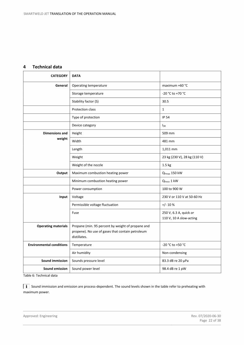
4 Technical data
CATEGORY DATA
General Operating temperature maximum +60 °C
Storage temperature -20 °C to +70 °C
Stability factor (S) 30.5
Protection class 1
Type of protection IP 54
Device category I3R
Dimensions and
weight
Height 509 mm
Width 481 mm
Length 1,011 mm
Weight 23 kg (230 V), 28 kg (110 V)
Weight of the nozzle 1.5 kg
Output Maximum combustion heating power QFmax 150 kW
Minimum combustion heating power QFmin 1 kW
Power consumption 100 to 900 W
Input Voltage 230 V or 110 V at 50-60 Hz
Permissible voltage fluctuation +/- 10 %
Fuse 250 V, 6.3 A, quick or
110 V, 10 A slow-acting
Operating materials Propane (min. 95 percent by weight of propane and
propene). No use of gases that contain petroleum
distillates.
Environmental conditions Temperature -20 °C to +50 °C
Air humidity Non-condensing
Sound immission Sounds pressure level 83.3 dB re 20 µPa
Sound emission Sound power level 98.4 dB re 1 pW
Table 6: Technical data
Sound immission and emission are process-dependent. The sound levels shown in the table refer to preheating with
maximum power.

Approved: Engineering Rev. 07/2020-06-30 Page 23 of 38
SMARTWELD JET TRANSLATION OF THE OPERATION MANUAL
To ensure control of the flame in the device, the device has an automatic polarity inverter switch on the inside. For
measurements where the protective earth is disconnected (e.g. protective earth current), you must ensure that the device is
started up with the protective earth connected and that the protective earth is only disconnected when P1 appears on the display.
For the measurement with reversed phase connection, the device must be completely disconnected from the electricity network
and then reconnected to the network with the protective earth connected. Here too, the protective earth must not be
disconnected for the measurement until P1 appears on the device display. You must also ensure that the various screws in the
housing are earthed or isolated.
The gas pressure regulator on the Smartweld Jet sets it to the local gas supply and to local delivery pressure, and is included in
device category I3R for liquefied gas.
Gases containing petroleum distillates must not be used with the Smartweld Jet because they contain liquid hydrocarbons that
can damage the Smartweld Jet.

Approved: Engineering Rev. 07/2020-06-30 Page 24 of 38
SMARTWELD JET TRANSLATION OF THE OPERATION MANUAL
5 Operating conditions
This chapter describes the operating conditions, which must be in place for proper operation of the Smartweld Jet.
NOTICE
The Smartweld Jet may not be operated if the actual conditions deviate from the operating conditions. Always check whether all
the operating conditions are met before commissioning the Smartweld Jet.
SIZE VALUE
Ambient temperature (min.) -20 °C
Ambient temperature (max.) +50 °C
Air humidity Non-condensing environment
Table 7: Operating conditions
The following operating conditions must also be fulfilled for the Smartweld Jet and its accessories:
• The Smartweld Jet may only be used when it is in a technically undamaged and serviceable condition.
• The Smartweld Jet may only be used when connected to power supplies that have a protective earthing connection and ground
fault circuit interrupter or insulation monitoring with automatic disconnection.
• The power supply (feed-in) must be equipped with an automatic shut-off function. The Smartweld Jet has no protection by
automatic shut-off of the supply.
• The Smartweld Jet may only be operated on a track that has been locked and secured in accordance with the specifications of
the railway company.
• The Smartweld Jet may only be operated with propane with a purity in accordance with EN 589 (min. 95 percent by weight of
propane and propene).
• The Smartweld Jet may only be used with sufficient ventilation and aeration.
• The Smartweld Jet may not be operated with stormy weather.
• The position of use must be observed to prevent the penetration of moisture.
Approved: Engineering Rev. 07/2020-06-30 Page 25 of 38
SMARTWELD JET TRANSLATION OF THE OPERATION MANUAL
6 Transport
This chapter contains all information that is required for the proper transport of all components of the Smartweld Jet.
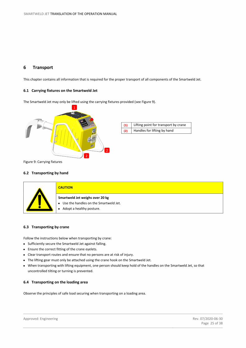
6.1 Carrying fixtures on the Smartweld Jet
The Smartweld Jet may only be lifted using the carrying fixtures provided (see Figure 9).
Figure 9: Carrying fixtures
6.2 Transporting by hand
CAUTION
Smartweld Jet weighs over 20 kg
• Use the handles on the Smartweld Jet.
• Adopt a healthy posture.
6.3 Transporting by crane
Follow the instructions below when transporting by crane:
• Sufficiently secure the Smartweld Jet against falling.
• Ensure the correct fitting of the crane eyelets.
• Clear transport routes and ensure that no persons are at risk of injury.
• The lifting gear must only be attached using the crane hook on the Smartweld Jet.
• When transporting with lifting equipment, one person should keep hold of the handles on the Smartweld Jet, so that
uncontrolled tilting or turning is prevented.
6.4 Transporting on the loading area
Observe the principles of safe load securing when transporting on a loading area.
(1) Lifting point for transport by crane
(2)2 Handles for lifting by hand
2
2
1

Approved: Engineering Rev. 07/2020-06-30 Page 26 of 38
SMARTWELD JET TRANSLATION OF THE OPERATION MANUAL
7 Commissioning
This chapter contains all information that is required for proper commissioning of the Smartweld Jet. Carry out commissioning in
the sequence of the following chapters.
7.1 Initial commissioning
Follow the instructions below during initial commissioning:
1. Push the nozzle onto the torch tube so that the opening is against the stop and align (see Figure 10).
Figure10: Fitting the nozzle
2. Correctly fasten the nozzle with the clamping device (see Figure 11).
Figure 11: Fastening the nozzle
Incorrect alignment of the nozzle may lead to subsequent improper insertion into the welding mould.
The nozzle can also remain inserted during transport.
7.2 Checks before commissioning
Check the proper state of the Smartweld Jet each day before commissioning, especially:
1. Check the filter and clean/replace if necessary (see chapter 11 “Maintenance”).
2. Check the Smartweld Jet and its components (electricity and gas connection, among others) for signs of damage, such as
cracking and breakage.
3. Check whether the nozzle is correctly fitted facing downwards and is secured.
4. Check all connecting parts of the gas supply for gas leakages.

Approved: Engineering Rev. 07/2020-06-30 Page 27 of 38
SMARTWELD JET TRANSLATION OF THE OPERATION MANUAL
The Smartweld Jet may only be used when it is in a technically undamaged and serviceable condition.
If the Smartweld Jet is not in a satisfactory condition, reestablish proper functioning or discuss how to proceed with the
manufacturer.
A slight adjustment of the control voltage in the pre-heating program must be made before welding work at heights
exceeding 1,500 m. Contact the system provider for this.
The exposed metal parts of the Smartweld Jet are connected to the protective conductor of the power supply. If several
Smartweld Jet are used on a track at the same time, the notification of track occupation may be triggered during operation on the
same power supply. Adjacent rails can be connected to each other in an electrically conductive manner via the protective
conductor. This is also possible if the Smartweld Jet is simultaneously operated on a power source with other electrically powered
devices and is used on different rails. Inform yourself about whether the notification of track occupation system is active in your
work section and carry out work on adjacent tracks sequentially in case of doubt.
7.3 Mounting the clamping device
Follow the instructions below when mounting the clamping device:
1. Place the clamping device onto the rail ends using a setting gauge as such, that the arms for fastening the mould shoes are
facing towards the welding gap. The tensioning clamp must encompass the rail head in this case.
2. Secure the clamping device on the rail using the clamping screw.
3. Observe the straight fitting of the clamping device on the rail when tightening the clamping screw. The mandrel of the clamping
device must be aligned parallel to the rail axis.
WARNING
Toppling of the Smartweld Jet during operation
The Smartweld Jet can topple over if the clamping device is insufficiently secured to the rail. This can result
in injuries and damage.
• Carry out proper assembly and check.
• Always wear personal protective equipment (see chapter 2.11 “Personal protective equipment”).
7.4 Preparing the location of welding point
Prepare the location of welding point in accordance with the supporting code of practice (see chapter 1.5 “Supporting
documents”).
7.5 Setting up the Smartweld Jet
Follow the instructions below when setting up the Smartweld Jet:
1. Position the Smartweld Jet on the mandrel of the clamping device. Ensure it is seated firmly!
2. Align the Smartweld Jet with the positional aid of the clamping device as such, that the nozzle is centred over the welding gap.
3. Check the height setting of the Smartweld Jet using the setting gauge. Refer to the corresponding code of practice for the correct height.

Approved: Engineering Rev. 07/2020-06-30 Page 28 of 38
SMARTWELD JET TRANSLATION OF THE OPERATION MANUAL
7.6 Establishing the electricity and gas supply
Follow the instructions below when establishing the electricity and gas supply:
1. Connect the power cable (see Figure 12, on the left), use the corresponding correct power cable for the respective variant.
Deactivate the emergency stop switch by turning the switch (see Figure 12, on the right). A yellow or green ring is visible under
the switch when deactivated.
Figure 12 : left-hand image: connecting the power cable; right-hand image: emergency stop switch deactivated (230 V)
NOTICE
Please ensure that the power supply used to operate the Smartweld Jet complies with the technical data relating to electrical
input set out in Table 6 (230 V or 110 V, 50-60 Hz, permissible fluctuation ±10%). Generators used must be in normal operating
mode (See Chapter 10 “Troubleshooting”, Table 9 Error and information codes).
When operating the Smartweld Jet using a power generator, it is important to always start the generator first and only then
connect the cable to the Smartweld Jet (danger of damage to the Smartweld Jet). Make sure that the Smartweld Jet is not
preheating when operating other electrical machines. Voltage peaks can occur in both and this can lead to the overvoltage
protection of the Smartweld Jet being triggered.
When the overvoltage protection responds, the Smartweld Jet power supply is cut off and the Smartweld Jet turns off. To re-
activate the electronics, the Smartweld Jet must then be voltage free. This is carried out by pressing the emergency stop switch
or disconnecting from the power source.
NOTICE
Message CH E: this message may appear while operating the Smartweld Jet using a power generator. The earthing of the power
generator must be checked and the message must be acknowledged by pressing the STOP button.
2. Prepare the gas supply, consisting of the pressure reducing valve, gas leakage shut-off device and gas hose, check and connect
with the liquid gas cylinder.
3. Connect the other end of the gas hose to the Smartweld Jet using the disconnect coupling (see Figure13).
The gas leakage shut-off device shuts off the gas supply when there is an excessive pressure drop in the gas line.

Approved: Engineering Rev. 07/2020-06-30 Page 29 of 38
SMARTWELD JET TRANSLATION OF THE OPERATION MANUAL
Figure 13: Connecting the gas hose
CAUTION
Position the gas hose and the power cable such that there is no risk of stumbling.
4. Slowly turn up the gas cylinder valve to establish the gas supply.
Gas only flows through the Smartweld Jet, after the pre-heating program has been started, the fan is running and the
necessary air pressure is reached (monitored by the air pressure switch). Since the air must initially escape from the system, the
first pre-heating may be automatically interrupted after connecting the gas hose. An error message appears in the display. The pre-
heating must be restarted after the reset button or the stop button is pressed.
The pressure reducing valve used includes an overpressure safety shut-off device, type OPSO (Over-Pressure-Shut-Off). This
acts autonomously and protects any gas appliances connected to it from unacceptably high levels of pressure. The red/green visual
indicator shows whether the unit has responded or not. When operational, this display is green. If overpressure occurs in the
pressure reducing valve, the device triggers and interrupts the flow of gas. The visual display jumps to red and the operator can see
immediately that the overpressure shut-off unit is responsible for interrupting operation of the system. After the trigger, the device
has to be manually unlocked as follows in order to restore the gas supply (Figure 14):
Figure 14: Resetting the overpressure safety shut-off device OPSO

Approved: Engineering Rev. 07/2020-06-30 Page 30 of 38
SMARTWELD JET TRANSLATION OF THE OPERATION MANUAL
1. Unscrew protective cap A manually.
2. Turn protective cap A over and pull out spindle B using unlocking device C until spindle B noticeably engages and remains
open.
3. Screw on protective cap A again.
4. OPSO is ready for operation → visual display GREEN.
Further information can be found in the separate operating instructions of the pressure regulator.

Approved: Engineering Rev. 07/2020-06-30 Page 31 of 38
SMARTWELD JET TRANSLATION OF THE OPERATION MANUAL
8 Operation
This chapter contains all information that is required for proper operation of the Smartweld Jet.
Care must be taken to ensure the propane supply is not interrupted, e.g. by stepping on the hose or bending it.
8.1 Pre-heating the rails and casting system
CAUTION
Delayed ignition
The gas-air mixture is only ignited approx. 10 seconds after the fan starts up.
• Always wear personal protective equipment (see chapter 2.11 “Personal protective equipment”).
• Maintain a safe distance.
CAUTION
Risk of burning due to incorrect pre-heating program
If the incorrect pre-heating program is selected, the casting system may get too hot or be destroyed
altogether, causing sparks or even steel discharge. This can lead to burns.
Pay particular attention to the following precautions during commissioning and operation:
• Always wear personal protective equipment (see chapter 2.11 “Personal protective equipment”)
• Follow the instructions in this Operation Manual and observe the notes.
• Set the pre-heating program corresponding to the casting system used with the respective Thermit®
welding procedure.
• Follow the supporting code of practice (see chapter 1.5 “Supporting documents”).
Follow the instructions below when pre-heating the rail ends and casting system:
1. Select the required pre-heating program with UP and DOWN (see Figure 15).
Figure 15: Selection of the pre-heating program
Special parameters can be implemented after consultation with the manufacturer by using a specific pre-heating program.

Approved: Engineering Rev. 07/2020-06-30 Page 32 of 38
SMARTWELD JET TRANSLATION OF THE OPERATION MANUAL
2. Confirm the selection with START.
3. Press twice on START within three seconds to start the pre-heating program.
After reaching the necessary output of the Smartweld Jet, the remaining output is indicated in the display (format: mm:ss).
The fan runs immediately at approx 10 % of the maximum speed. The gas valve is then opened. The gas-air mixture is only
ignited approx. 10 seconds after the fan starts up, which generates a visible jet flame from the nozzle. The fan will reach its final
speed dependent on the pre-heating program.
The gas feed is automatically stopped. E:nd is indicated in the display.
4. Remove the Smartweld Jet from the clamping device and place it in a suitable location after ending the pre-heating program. If
necessary, start the torch cooling program there with COOLER.
C:on is indicated on the display during the torch cooling program.
Refer to the corresponding code of practice for the Thermit® welding procedure for all other work steps.
The most recently used pre-heating program automatically appears in the display after the cooling mode time has finished.
Make sure to select the correct Smartweld Jet program. The programs can be selected by pressing the UP and DOWN arrow
keys on the display. The adjustment is automatic when using the Smartweld Application.
8.2 Using the Smartweld Jet via Smartweld Application
Information on how to use the Smartweld Jet via the Smartweld Application is included in the software manual for the Smartweld
Application. Please proceed in accordance with these instructions.
If you wish to use the Smartweld Jet with the application via Bluetooth®, you must first switch on Bluetooth. Simply select the
available Smartweld Jet in the application to connect the device.
For safety reasons, the Smartweld Jet cannot be started using the application. After pressing the CONNECT TO SMARTWELD JET
softkey in the application, press START on the Smartweld Jet twice within 3 seconds.
8.3 Transferring the Smartweld Jet
The Smartweld Jet may not be transferred during active operation! Follow the instructions below to transfer to a new location of
welding point:
1. Finish work on the location of welding point (see chapter 9.1 “Finishing work at location of welding point”).
2. Transport the Smartweld Jet to the next location of welding point. Observe the transport conditions (see chapter 6 “Transport”).
3. Carry out commissioning (see chapter 7 “Commissioning”) of the Smartweld Jet at the new location of welding point.
8.4 Stop Smartweld Jet using the emergency stop switch
In an unforeseen and hazardous situation, press the emergency stop switch to stop the Smartweld Jet immediately (see Figure 16).
The power and gas supply to the Smartweld Jet is interrupted.

Approved: Engineering Rev. 07/2020-06-30 Page 33 of 38
SMARTWELD JET TRANSLATION OF THE OPERATION MANUAL
Figure 16: Emergency stop switch
WARNING
Hot surface on the nozzle
Risk of burning due to contact. The fan to cool the nozzle stops running.
• Always wear personal protective equipment (see chapter 2.11 “Personal protective equipment”).
• Do not touch the nozzle.
• Let the nozzle cool down.
8.5 Switch on the Smartweld Jet again after pressing the emergency stop switch
WARNING
Do not use a defective Smartweld Jet!
• Before restarting, eliminate the cause which necessitated use of the emergency stop switch.
• Ensure that there are no dangers to persons.
• Ensure that the Smartweld Jet is in a technically flawless state and ready for operation.
1. Remove the power cable.
2. Remove the gas hose.
3. Eliminate the cause which necessitated use of the emergency stop switch and restore the proper condition of the Smartweld Jet.
Inform the manufacturer if necessary.
4. Pull out the engaged emergency stop switch counter-clockwise.
5. Re-connect the gas hose.
6. Re-connect the power cable.

Approved: Engineering Rev. 07/2020-06-30 Page 34 of 38
SMARTWELD JET TRANSLATION OF THE OPERATION MANUAL
9 Decommissioning
This chapter contains all information that is required for proper decommissioning of the Smartweld Jet.
9.1 Finishing work at location of welding point
DANGER
Hot surface on the nozzle
Risk of burning due to contact.
• Always wear personal protective equipment (see chapter 2.11 “Personal protective equipment”).
• Let the pre-heating program completely finish.
• Do not touch the nozzle.
• Let the nozzle cool down.
Follow the instructions below when finishing work at the location of welding point:
1. Allow the Smartweld Jet to cool down.
2. Remove the power cable and store to the side carefully.
3. Remove the gas hose and store to the side carefully.
9.2 Daily decommissioning
Follow the instructions below when finishing work at the location of welding point:
1. Finish work at the welding point (see chapter 9.1)
2. Shut off the gas cylinder valve to stop the gas supply.
3. Clean the Smartweld Jet (see chapter 12 “Cleaning/care”).
4. Shake out the filter and check for damage. Change the filter if it is damaged or no longer functional (see chapter 11
“Maintenance”.)
5. Check the Smartweld Jet and its components for signs of damage. Inform the manufacturer if applicable.
6. Either secure the Smartweld Jet against unauthorised access or prepare it for transport (see chapter 6.2 “Transporting by hand”).

Approved: Engineering Rev. 07/2020-06-30 Page 35 of 38
SMARTWELD JET TRANSLATION OF THE OPERATION MANUAL
10 Troubleshooting
This chapter contains a list of faults which can occur with the Smartweld Jet.
NOTICE
If any further maintenance work is required for troubleshooting, other than filter change, then this must only be undertaken by
the authorised service partners.
FAULT POSSIBLE CAUSE REMEDY
Fan does not start. Power supply is interrupted
or defective.
Check the plug connection and initiate a restart.
Inform service partner in case of recurrence.
Smartweld Jet does not
ignite.
Spark plug is contaminated. Contact the service partner.
Smartweld Jet does not
switch on, display remains
black.
Power supply is interrupted
by overloaded fuse.
1. Remove the power cable and store to the side carefully.
2. Remove the gas hose and store to the side carefully.
3. Shut off the gas cylinder valve to stop the gas supply.
4. Remove the covers of both fuse boxes using a suitable
screwdriver.
5. Check the fuses and replace them with fuses of the same type if
necessary (250 V, 6.3 A, quick or 110 V, 10 A slowly-acting).
Re-establish the power and gas supply (see chapter 7.6
“Establishing the electricity and gas supply”).
Inform service partner in case of recurrence.
Emergency stop switch is
activated.
Deactivate the emergency stop switch by turning the switch.
Power supply is interrupted
or defective.
Check the plug connection and initiate a restart.
Inform service partner in case of recurrence.
The pre-heating does not
automatically end.
Program sequence is
disturbed.
Interrupt the pre-heating program with STOP or EMERGENCY STOP.
Inform service partner in case of recurrence.
Table 8: Troubleshooting
When an error occurs, it is indicated by an error LED and an error code (see Table 9) in the display.

Approved: Engineering Rev. 07/2020-06-30 Page 36 of 38
SMARTWELD JET TRANSLATION OF THE OPERATION MANUAL
CODE POSSIBLE CAUSE REMEDY
Err1 Gas pressure is too low. Check the cylinder fill level and the gas supply system as well as the
overpressure shut-off device (see chapter 7.6 “Establishing the
electricity and gas supply”).
Err2 Air pressure is too low. Clean/change the filter and initiate a restart.
Inform service partner in case of recurrence.
Err3 Firing mechanism is
defective.
Press RESET and switch the device off.
Inform service partner in case of recurrence.
Err4 Firing mechanism has not
activated fan.
Interrupt the pre-heating program with STOP and initiate a restart.
Inform service partner in case of recurrence.
Err5 Motor speed limit is
exceeded.
Contact the service partner.
Err6 Motor speed limit is
undershot.
Contact the service partner.
Err7 Motor output limit is
exceeded.
Contact the service partner.
Err8 Motor output limit is
undershot.
Contact the service partner.
Err9 Motor voltage limit is
exceeded.
Contact the service partner.
ErrA Motor voltage limit is
undershot.
Contact the service partner.
CH E Assignment of phase and
neutral conductor is not
recognised.
Check power supply and earthing, confirm the message with STOP
and continue operation.
Err3, Err4 Power supply does not
supply the required
electrical input values.
Make sure that the Smartweld Jet is operated on power grids or
generators having the following characteristics: 230 V or 110 V, 50-
60 HZ, permissible fluctuation ±10%.
Generators used must be in normal operating mode.
Err5 to Err9, ErrA Limit values in the
Smartweld Application
and/or Smartweld Jet are
not current.
Check to ensure that the very latest version of the Application is
installed. Carry out Smartweld Jet program update. Also refer to the
operating instructions for Smartweld Application 3.3 updates.
Table 9: Error and information codes
Approved: Engineering Rev. 07/2020-06-30 Page 37 of 38
SMARTWELD JET TRANSLATION OF THE OPERATION MANUAL
11 Maintenance
The Smartweld Jet must be serviced annually by an authorised service partner. The operator is responsible for compliance with the
maintenance cycles.
11.1 Filter maintenance: Cleaning and replacement
This chapter contains all information that is required for proper handling of the filter.
The filter is cleaned and replaced as required. A visual inspection of the filter must be carried out daily to check for obvious damage
and coarse dirt, which should be removed.
11.2 Clean filter
Follow the instructions below when cleaning the filter:
1. Take the Smartweld Jet out of operation (see chapter 9 “Decommissioning”).
2. Remove the filter from the filter housing.
3. Shake out the filter to free it from coarse containments.
4. Check the filter for damage. Replace the filter if it is damaged or no longer functional (see chapter 11.3 “Changing the filter”).
5. Insert the filter back into the filter housing and close the filter housing.
11.3 Changing the filter
Follow the instructions below when changing the filter:
1. Take the Smartweld Jet out of operation (see chapter 9 “Decommissioning”).
2. Remove the old filter from the filter housing.
3. Insert the new, undamaged filter into the filter housing and close the filter housing.
4. If necessary, put the Smartweld Jet back into operation (see chapter 7 “Commissioning”).
12 Cleaning/care
We recommend cleaning the Smartweld Jet as part of daily decommissioning.
Follow the instructions below during cleaning:
1. Take the Smartweld Jet out of operation (see chapter 9 “Decommissioning”).
2. Allow the Smartweld Jet to cool down.
3. Clean the from the outside using a commercially available plastic cleaner.
• Never let water flow on or into the Smartweld Jet.
• Never use combustible or highly flammable cleaning agents.

Approved: Engineering Rev. 07/2020-06-30 Page 38 of 38
SMARTWELD JET TRANSLATION OF THE OPERATION MANUAL
13 Spare and wearing parts
The Smartweld Jet may only be operated with original spare and wearing parts. The following are classified original spare and
wearing parts:
• Filter
• Nozzle
• Safety fuse
Spare and wearing parts can be ordered from any company within the Goldschmidt Group.
14 Storage
This chapter contains all information that is required for proper storage of the Smartweld Jet.
14.1 Storage conditions
The following storage conditions must always be respected:
• Storage temperature: -20 °C to +70 °C
• UV light-protected environment
• Storage without moisture transfer to the Smartweld Jet
• Do not store in the immediate vicinity of heaters or other heat sources above +70 °C to prevent material deformities.
• Store in a dust-free location (use optional transport and storage box).
14.2 Recommissioning after extended downtimes
Follow the instructions below when recommissioning the Smartweld Jet after extended downtimes:
1. Thoroughly clean the Smartweld Jet (see chapter 12 “Cleaning/care“).
2. Check the functionality of the emergency stop switch.
3. Check the effectiveness of the operating elements and displays.
4. Before use, put the Smartweld Jet into operation correctly (see chapter 7 “Commissioning”).
15 Disposal/recycling
This chapter contains all information that is required for the proper disposal of all components of the Smartweld Jet.
NOTICE
Comply with environmentally friendly disposal of the Smartweld Jet and its components.
At the end of the service life of the Smartweld Jet, the operator must ensure the disposal of each individual component of the
Smartweld Jet in accordance with the applicable regulations. The Smartweld Jet must be disposed of as electrical waste.