smartstack els100-8txuf2 fast ethernet...
TRANSCRIPT

9033029
SmartSTACKELS100-8TXUF2
FAST ETHERNET SWITCH
INSTALLATIONAND
USER GUIDE
ELS100-8TXUF2.book Page -i Friday, June 4, 1999 4:01 PM

ELS100-8TXUF2.book Page 0 Friday, June 4, 1999 4:01 PM

Notice
9033029 i
NOTICE
Cabletron Systems reserves the right to make changes in specifications and other information contained in this document without prior notice. The reader should in all cases consult Cabletron Systems to determine whether any such changes have been made.
The hardware, firmware, or software described in this manual is subject to change without notice.
IN NO EVENT SHALL CABLETRON SYSTEMS BE LIABLE FOR ANY INCIDENTAL, INDIRECT, SPECIAL, OR CONSEQUENTIAL DAMAGES WHATSOEVER (INCLUDING BUT NOT LIMITED TO LOST PROFITS) ARISING OUT OF OR RELATED TO THIS MANUAL OR THE INFORMATION CONTAINED IN IT, EVEN IF CABLETRON SYSTEMS HAS BEEN ADVISED OF, KNOWN, OR SHOULD HAVE KNOWN, THE POSSIBILITY OF SUCH DAMAGES.
1999 by Cabletron Systems, Inc., P.O. Box 5005, Rochester, NH 03866-5005All Rights ReservedPrinted in Taiwan, R.O.C.
Order Number: 9033029 April 1999
Cabletron Systems, is a registered trademark and SmartSwitch is a trademark of Cabletron Systems, Inc.
All other product names mentioned in this manual may be trademarks or registered trademarks of their respective companies.
FCC NOTICE
This device complies with Part 15 of the FCC rules. Operation is subject to the following two conditions: (1) this device may not cause harmful interference, and (2) this device must accept any interference received, including interference that may cause undesired operation.
NOTE: This equipment has been tested and found to comply with the limits for a Class A digital device, pursuant to Part 15 of the FCC rules. These limits are designed to provide reasonable protection against harmful interference when the equipment is operated in a commercial environment. This equipment uses, generates, and can radiate radio frequency energy and if not installed in accordance with the operator’s manual, may cause harmful interference to radio communications. Operation of this equipment in a residential area is likely to cause interference in which case the user will be required to correct the interference at his own expense.
WARNING: Changes or modifications made to this device which are not expressly approved by the party responsible for compliance could void the user’s authority to operate the equipment.
Only qualified personnel should perform installation procedures.
ELS100-8TXUF2.book Page i Friday, June 4, 1999 4:01 PM

Notice
ii 9033029
INDUSTRY CANADA NOTICE
This digital apparatus does not exceed the Class A limits for radio noise emissions from digital apparatus set out in the Radio Interference Regulations of the Canadian Department of Communications.
Le présent appareil numérique n’émet pas de bruits radioélectriques dépassant les limites applicables aux appareils numériques de la class A prescrites dans le Règlement sur le brouillage radioélectrique édicté par le ministère des Communications du Canada.
VCCI NOTICE
This is a Class A product based on the standard of the Voluntary Control Council for Interference by Information Technology Equipment (VCCI). If this equipment is used in a domestic environment, radio disturbance may arise. When such trouble occurs, the user may be required to take corrective actions.
ELS100-8TXUF2.book Page ii Friday, June 4, 1999 4:01 PM

Notice
9033029 iii
CABLETRON SYSTEMS, INC.PROGRAM LICENSE AGREEMENT
IMPORTANT: THIS LICENSE APPLIES FOR USE OF PRODUCT IN THE FOLLOWING GEOGRAPHICAL REGIONS:
CANADAMEXICOCENTRAL AMERICASOUTH AMERICA
BEFORE OPENING OR UTILIZING THE ENCLOSED PRODUCT, CAREFULLY READ THIS LICENSE AGREEMENT.
This document is an agreement (“Agreement”) between You, the end user, and Cabletron Systems, Inc. (“Cabletron”) that sets forth your rights and obligations with respect to the Cabletron software program (“Program”) in the package. The Program may be contained in firmware, chips or other media. UTILIZING THE ENCLOSED PRODUCT, YOU ARE AGREEING TO BECOME BOUND BY THE TERMS OF THIS AGREEMENT, WHICH INCLUDES THE LICENSE AND THE LIMITATION OF WARRANTY AND DISCLAIMER OF LIABILITY. IF YOU DO NOT AGREE TO THE TERMS OF THIS AGREEMENT, RETURN THE UNOPENED PRODUCT TO CABLETRON OR YOUR DEALER, IF ANY, WITHIN TEN (10) DAYS FOLLOWING THE DATE OF RECEIPT FOR A FULL REFUND.
IF YOU HAVE ANY QUESTIONS ABOUT THIS AGREEMENT, CONTACT CABLETRON SYSTEMS (603) 332-9400. Attn: Legal Department.
1. LICENSE. You have the right to use only the one (1) copy of the Program provided in this package subject to the terms and conditions of this License Agreement.
You may not copy, reproduce or transmit any part of the Program except as permitted by the Copyright Act of the United States or as authorized in writing by Cabletron.
2. OTHER RESTRICTIONS. You may not reverse engineer, decompile, or disassemble the Program.
3. APPLICABLE LAW. This License Agreement shall be interpreted and governed under the laws and in the state and federal courts of New Hampshire. You accept the personal jurisdiction and venue of the New Hampshire courts.
4. EXPORT REQUIREMENTS. You understand that Cabletron and its Affiliates are subject to regulation by agencies of the U.S. Government, including the U.S. Department of Commerce, which prohibit export or diversion of certain technical products to certain countries, unless a license to export the product is obtained from the U.S. Government or an exception from obtaining such license may be relied upon by the exporting party.
If the Program is exported from the United States pursuant to the License Exception CIV under the U.S. Export Administration Regulations, You agree that You are a civil end user of the Program and agree that You will use the Program for civil end uses only and not for military purposes.
ELS100-8TXUF2.book Page iii Friday, June 4, 1999 4:01 PM

Notice
iv 9033029
If the Program is exported from the United States pursuant to the License Exception TSR under the U.S. Export Administration Regulations, in addition to the restriction on transfer set forth in Sections 1 or 2 of this Agreement, You agree not to (i) reexport or release the Program, the source code for the Program or technology to a national of a country in Country Groups D:1 or E:2 (Albania, Armenia, Azerbaijan, Belarus, Bulgaria, Cambodia, Cuba, Estonia, Georgia, Iraq, Kazakhstan, Kyrgyzstan, Laos, Latvia, Libya, Lithuania, Moldova, North Korea, the People’s Republic of China, Romania, Russia, Rwanda, Tajikistan, Turkmenistan, Ukraine, Uzbekistan, Vietnam, or such other countries as may be designated by the United States Government), (ii) export to Country Groups D:1 or E:2 (as defined herein) the direct product of the Program or the technology, if such foreign produced direct product is subject to national security controls as identified on the U.S. Commerce Control List, or (iii) if the direct product of the technology is a complete plant o r any major component of a plant, export to Country Groups D:1 or E:2 the direct product of the plant or a major component thereof, if such foreign produced direct product is subject to national security controls as identified on the U.S. Commerce Control List or is subject to State Department controls under the U.S. Munitions List.
5. UNITED STATES GOVERNMENT RESTRICTED RIGHTS. The enclosed Product (i) was developed solely at private expense; (ii) contains “restricted computer software” submitted with restricted rights in accordance with section 52.227-19 (a) through (d) of the Commercial Computer Software-Restricted Rights Clause and its successors, and (iii) in all respects is proprietary data belonging to Cabletron and/or its suppliers. For Department of Defense units, the Product is considered commercial computer software in accordance with DFARS section 227.7202-3 and its successors, and use, duplication, or disclosure by the Government is subject to restrictions set forth herein.
6. EXCLUSION OF WARRANTY. Except as may be specifically provided by Cabletron in writing, Cabletron makes no warranty, expressed or implied, concerning the Program (including its documentation and media).
CABLETRON DISCLAIMS ALL WARRANTIES, OTHER THAN THOSE SUPPLIED TO YOU BY CABLETRON IN WRITING, EITHER EXPRESS OR IMPLIED, INCLUDING BUT NOT LIMITED TO IMPLIED WARRANTIES OF MERCHANTABILITY AND FITNESS FOR A PARTICULAR PURPOSE, WITH RESPECT TO THE PROGRAM, THE ACCOMPANYING WRITTEN MATERIALS, AND ANY ACCOMPANYING HARDWARE.
7. NO LIABILITY FOR CONSEQUENTIAL DAMAGES. IN NO EVENT SHALL CABLETRON OR ITS SUPPLIERS BE LIABLE FOR ANY DAMAGES WHATSOEVER (INCLUDING, WITHOUT LIMITATION, DAMAGES FOR LOSS OF BUSINESS, PROFITS, BUSINESS INTERRUPTION, LOSS OF BUSINESS INFORMATION, SPECIAL, INCIDENTAL, CONSEQUENTIAL, OR RELIANCE DAMAGES, OR OTHER LOSS) ARISING OUT OF THE USE OR INABILITY TO USE THIS CABLETRON PRODUCT, EVEN IF CABLETRON HAS BEEN ADVISED OF THE POSSIBILITY OF SUCH DAMAGES. BECAUSE SOME STATES DO NOT ALLOW THE EXCLUSION OR LIMITATION OF LIABILITY FOR CONSEQUENTIAL OR INCIDENTAL DAMAGES, OR IN THE DURATION OR LIMITATION OF IMPLIED WARRANTIES IN SOME INSTANCES, THE ABOVE LIMITATION AND EXCLUSIONS MAY NOT APPLY TO YOU.
ELS100-8TXUF2.book Page iv Friday, June 4, 1999 4:01 PM

Notice
9033029 v
CABLETRON SYSTEMS SALES AND SERVICE, INC.PROGRAM LICENSE AGREEMENT
IMPORTANT: THIS LICENSE APPLIES FOR USE OF PRODUCT IN THE UNITED STATES OF AMERICA AND BY UNITED STATES OF AMERICA GOVERNMENT END USERS.
BEFORE OPENING OR UTILIZING THE ENCLOSED PRODUCT, CAREFULLY READ THIS LICENSE AGREEMENT.
This document is an agreement (“Agreement”) between You, the end user, and Cabletron Systems Sales and Service, Inc. (“Cabletron”) that sets forth your rights and obligations with respect to the Cabletron software program (“Program”) in the package. The Program may be contained in firmware, chips or other media. UTILIZING THE ENCLOSED PRODUCT, YOU ARE AGREEING TO BECOME BOUND BY THE TERMS OF THIS AGREEMENT, WHICH INCLUDES THE LICENSE AND THE LIMITATION OF WARRANTY AND DISCLAIMER OF LIABILITY. IF YOU DO NOT AGREE TO THE TERMS OF THIS AGREEMENT, RETURN THE UNOPENED PRODUCT TO CABLETRON OR YOUR DEALER, IF ANY, WITHIN TEN (10) DAYS FOLLOWING THE DATE OF RECEIPT FOR A FULL REFUND.
IF YOU HAVE ANY QUESTIONS ABOUT THIS AGREEMENT, CONTACT CABLETRON SYSTEMS (603) 332-9400. Attn: Legal Department.
1. LICENSE. You have the right to use only the one (1) copy of the Program provided in this package subject to the terms and conditions of this License Agreement.
You may not copy, reproduce or transmit any part of the Program except as permitted by the Copyright Act of the United States or as authorized in writing by Cabletron.
2. OTHER RESTRICTIONS. You may not reverse engineer, decompile, or disassemble the Program.
3. APPLICABLE LAW. This License Agreement shall be interpreted and governed under the laws and in the state and federal courts of New Hampshire. You accept the personal jurisdiction and venue of the New Hampshire courts.
4. EXPORT REQUIREMENTS. You understand that Cabletron and its Affiliates are subject to regulation by agencies of the U.S. Government, including the U.S. Department of Commerce, which prohibit export or diversion of certain technical products to certain countries, unless a license to export the product is obtained from the U.S. Government or an exception from obtaining such license may be relied upon by the exporting party.
If the Program is exported from the United States pursuant to the License Exception CIV under the U.S. Export Administration Regulations, You agree that You are a civil end user of the Program and agree that You will use the Program for civil end uses only and not for military purposes.
ELS100-8TXUF2.book Page v Friday, June 4, 1999 4:01 PM

Notice
vi 9033029
If the Program is exported from the United States pursuant to the License Exception TSR under the U.S. Export Administration Regulations, in addition to the restriction on transfer set forth in Sections 1 or 2 of this Agreement, You agree not to (i) reexport or release the Program, the source code for the Program or technology to a national of a country in Country Groups D:1 or E:2 (Albania, Armenia, Azerbaijan, Belarus, Bulgaria, Cambodia, Cuba, Estonia, Georgia, Iraq, Kazakhstan, Kyrgyzstan, Laos, Latvia, Libya, Lithuania, Moldova, North Korea, the People’s Republic of China, Romania, Russia, Rwanda, Tajikistan, Turkmenistan, Ukraine, Uzbekistan, Vietnam, or such other countries as may be designated by the United States Government), (ii) export to Country Groups D:1 or E:2 (as defined herein) the direct product of the Program or the technology, if such foreign produced direct product is subject to national security controls as identified on the U.S. Commerce Control List, or (iii) if the direct product of the technology is a complete plant o r any major component of a plant, export to Country Groups D:1 or E:2 the direct product of the plant or a major component thereof, if such foreign produced direct product is subject to national security controls as identified on the U.S. Commerce Control List or is subject to State Department controls under the U.S. Munitions List.
5. UNITED STATES GOVERNMENT RESTRICTED RIGHTS. The enclosed Product (i) was developed solely at private expense; (ii) contains “restricted computer software” submitted with restricted rights in accordance with section 52.227-19 (a) through (d) of the Commercial Computer Software-Restricted Rights Clause and its successors, and (iii) in all respects is proprietary data belonging to Cabletron and/or its suppliers. For Department of Defense units, the Product is considered commercial computer software in accordance with DFARS section 227.7202-3 and its successors, and use, duplication, or disclosure by the Government is subject to restrictions set forth herein.
6. EXCLUSION OF WARRANTY. Except as may be specifically provided by Cabletron in writing, Cabletron makes no warranty, expressed or implied, concerning the Program (including its documentation and media).
CABLETRON DISCLAIMS ALL WARRANTIES, OTHER THAN THOSE SUPPLIED TO YOU BY CABLETRON IN WRITING, EITHER EXPRESS OR IMPLIED, INCLUDING BUT NOT LIMITED TO IMPLIED WARRANTIES OF MERCHANTABILITY AND FITNESS FOR A PARTICULAR PURPOSE, WITH RESPECT TO THE PROGRAM, THE ACCOMPANYING WRITTEN MATERIALS, AND ANY ACCOMPANYING HARDWARE.
7. NO LIABILITY FOR CONSEQUENTIAL DAMAGES. IN NO EVENT SHALL CABLETRON OR ITS SUPPLIERS BE LIABLE FOR ANY DAMAGES WHATSOEVER (INCLUDING, WITHOUT LIMITATION, DAMAGES FOR LOSS OF BUSINESS, PROFITS, BUSINESS INTERRUPTION, LOSS OF BUSINESS INFORMATION, SPECIAL, INCIDENTAL, CONSEQUENTIAL, OR RELIANCE DAMAGES, OR OTHER LOSS) ARISING OUT OF THE USE OR INABILITY TO USE THIS CABLETRON PRODUCT, EVEN IF CABLETRON HAS BEEN ADVISED OF THE POSSIBILITY OF SUCH DAMAGES. BECAUSE SOME STATES DO NOT ALLOW THE EXCLUSION OR LIMITATION OF LIABILITY FOR CONSEQUENTIAL OR INCIDENTAL DAMAGES, OR IN THE DURATION OR LIMITATION OF IMPLIED WARRANTIES IN SOME INSTANCES, THE ABOVE LIMITATION AND EXCLUSIONS MAY NOT APPLY TO YOU.
ELS100-8TXUF2.book Page vi Friday, June 4, 1999 4:01 PM

Notice
9033029 vii
CABLETRON SYSTEMS LIMITEDPROGRAM LICENSE AGREEMENT
IMPORTANT: THIS LICENSE APPLIES FOR THE USE OF THE PRODUCT IN THE FOLLOWING GEOGRAPHICAL REGIONS:
EUROPEMIDDLE EASTAFRICAASIAAUSTRALIAPACIFIC RIM
BEFORE OPENING OR UTILIZING THE ENCLOSED PRODUCT, CAREFULLY READ THIS LICENSE AGREEMENT.
This document is an agreement (“Agreement”) between You, the end user, and Cabletron Systems Limited (“Cabletron”) that sets forth your rights and obligations with respect to the Cabletron software program (“Program”) in the package. The Program may be contained in firmware, chips or other media. UTILIZING THE ENCLOSED PRODUCT, YOU ARE AGREEING TO BECOME BOUND BY THE TERMS OF THIS AGREEMENT, WHICH INCLUDES THE LICENSE AND THE LIMITATION OF WARRANTY AND DISCLAIMER OF LIABILITY. IF YOU DO NOT AGREE TO THE TERMS OF THIS AGREEMENT, RETURN THE UNOPENED PRODUCT TO CABLETRON OR YOUR DEALER, IF ANY, WITHIN TEN (10) DAYS FOLLOWING THE DATE OF RECEIPT FOR A FULL REFUND.
IF YOU HAVE ANY QUESTIONS ABOUT THIS AGREEMENT, CONTACT CABLETRON SYSTEMS (603) 332-9400. Attn: Legal Department.
1. LICENSE. You have the right to use only the one (1) copy of the Program provided in this package subject to the terms and conditions of this License Agreement.
You may not copy, reproduce or transmit any part of the Program except as permitted by the Copyright Act of the United States or as authorized in writing by Cabletron.
2. OTHER RESTRICTIONS. You may not reverse engineer, decompile, or disassemble the Program.
3. APPLICABLE LAW. This License Agreement shall be governed in accordance with English law. The English courts shall have exclusive jurisdiction in the event of any disputes.
4. EXPORT REQUIREMENTS. You understand that Cabletron and its Affiliates are subject to regulation by agencies of the U.S. Government, including the U.S. Department of Commerce, which prohibit export or diversion of certain technical products to certain countries, unless a license to export the product is obtained from the U.S. Government or an exception from obtaining such license may be relied upon by the exporting party.
If the Program is exported from the United States pursuant to the License Exception CIV under the U.S. Export Administration Regulations, You agree that You are a civil end user of the Program and agree that You will use the Program for civil end uses only and not for military purposes.
ELS100-8TXUF2.book Page vii Friday, June 4, 1999 4:01 PM

Notice
viii 9033029
If the Program is exported from the United States pursuant to the License Exception TSR under the U.S. Export Administration Regulations, in addition to the restriction on transfer set forth in Sections 1 or 2 of this Agreement, You agree not to (i) reexport or release the Program, the source code for the Program or technology to a national of a country in Country Groups D:1 or E:2 (Albania, Armenia, Azerbaijan, Belarus, Bulgaria, Cambodia, Cuba, Estonia, Georgia, Iraq, Kazakhstan, Kyrgyzstan, Laos, Latvia, Libya, Lithuania, Moldova, North Korea, the People’s Republic of China, Romania, Russia, Rwanda, Tajikistan, Turkmenistan, Ukraine, Uzbekistan, Vietnam, or such other countries as may be designated by the United States Government), (ii) export to Country Groups D:1 or E:2 (as defined herein) the direct product of the Program or the technology, if such foreign produced direct product is subject to national security controls as identified on the U.S. Commerce Control List, or (iii) if the direct product of the technology is a complete plant o r any major component of a plant, export to Country Groups D:1 or E:2 the direct product of the plant or a major component thereof, if such foreign produced direct product is subject to national security controls as identified on the U.S. Commerce Control List or is subject to State Department controls under the U.S. Munitions List.
5. UNITED STATES GOVERNMENT RESTRICTED RIGHTS. The enclosed Product (i) was developed solely at private expense; (ii) contains “restricted computer software” submitted with restricted rights in accordance with section 52.227-19 (a) through (d) of the Commercial Computer Software-Restricted Rights Clause and its successors, and (iii) in all respects is proprietary data belonging to Cabletron and/or its suppliers. For Department of Defense units, the Product is considered commercial computer software in accordance with DFARS section 227.7202-3 and its successors, and use, duplication, or disclosure by the Government is subject to restrictions set forth herein.
6. EXCLUSION OF WARRANTY. Except as may be specifically provided by Cabletron in writing, Cabletron makes no warranty, expressed or implied, concerning the Program (including its documentation and media).
CABLETRON DISCLAIMS ALL WARRANTIES, OTHER THAN THOSE SUPPLIED TO YOU BY CABLETRON IN WRITING, EITHER EXPRESS OR IMPLIED, INCLUDING BUT NOT LIMITED TO IMPLIED WARRANTIES OF MERCHANTABILITY AND FITNESS FOR A PARTICULAR PURPOSE, WITH RESPECT TO THE PROGRAM, THE ACCOMPANYING WRITTEN MATERIALS, AND ANY ACCOMPANYING HARDWARE.
7. NO LIABILITY FOR CONSEQUENTIAL DAMAGES. IN NO EVENT SHALL CABLETRON OR ITS SUPPLIERS BE LIABLE FOR ANY DAMAGES WHATSOEVER (INCLUDING, WITHOUT LIMITATION, DAMAGES FOR LOSS OF BUSINESS, PROFITS, BUSINESS INTERRUPTION, LOSS OF BUSINESS INFORMATION, SPECIAL, INCIDENTAL, CONSEQUENTIAL, OR RELIANCE DAMAGES, OR OTHER LOSS) ARISING OUT OF THE USE OR INABILITY TO USE THIS CABLETRON PRODUCT, EVEN IF CABLETRON HAS BEEN ADVISED OF THE POSSIBILITY OF SUCH DAMAGES. BECAUSE SOME STATES DO NOT ALLOW THE EXCLUSION OR LIMITATION OF LIABILITY FOR CONSEQUENTIAL OR INCIDENTAL DAMAGES, OR IN THE DURATION OR LIMITATION OF IMPLIED WARRANTIES IN SOME INSTANCES, THE ABOVE LIMITATION AND EXCLUSIONS MAY NOT APPLY TO YOU.
ELS100-8TXUF2.book Page viii Friday, June 4, 1999 4:01 PM

Notice
9033029 ix
DECLARATION OF CONFORMITY
Application of Council Directive(s): 89/336/EEC73/23/EEC
Manufacturer’s Name: Cabletron Systems, Inc.
Manufacturer’s Address: 35 Industrial WayPO Box 5005Rochester, NH 03867
European Representative Name:Mr. J. Solari
European Representative Address:Cabletron Systems LimitedNexus House, Newbury Business ParkLondon Road, NewburyBerkshire RG13 2PZ, England
Conformance to Directive(s)/Product Standards:EC Directive 89/336/EECEC Directive 73/23/EECEN 55022EN 50082-1EN 60950
Equipment Type/Environment:Networking Equipment, for use in a Commercial or Light Industrial Environment.
We the undersigned, hereby declare, under our sole responsibility, that the equipment packaged with this notice conforms to the above directives.
Manufacturer Legal Representative in Europe
Mr. Ronald Fotino Mr. J. Solari___________________________________ ___________________________________Full Name Full Name
Compliance Engineering Manager Managing Director - E.M.E.A.___________________________________ ___________________________________Title Title
Rochester, NH, USA Newbury, Berkshire, England___________________________________ ___________________________________Location Location
ELS100-8TXUF2.book Page ix Friday, June 4, 1999 4:01 PM

Notice
x 9033029
ELS100-8TXUF2.book Page x Friday, June 4, 1999 4:01 PM

9033029 Table of Contents xi
TABLE OF CONTENTS
PREFACE . . . . . . . . . . . . . . . . . . . . . . . . . . . . . . . . . . . . . . . . . . . . . . .XIIIPurpose. . . . . . . . . . . . . . . . . . . . . . . . . . . . . . . . . . . . . . . . . . . . . . . . . xiiiAudience . . . . . . . . . . . . . . . . . . . . . . . . . . . . . . . . . . . . . . . . . . . . . . . . xiiiConventions . . . . . . . . . . . . . . . . . . . . . . . . . . . . . . . . . . . . . . . . . . . . . xiii
Message Formats . . . . . . . . . . . . . . . . . . . . . . . . . . . . . . . . . . . . . xiiiOrganization . . . . . . . . . . . . . . . . . . . . . . . . . . . . . . . . . . . . . . . . . . . . . xiii
1. PRODUCT OVERVIEW . . . . . . . . . . . . . . . . . . . . . . . . . . . . . . . . . . . 1Description . . . . . . . . . . . . . . . . . . . . . . . . . . . . . . . . . . . . . . . . . . . . . . . 1Features . . . . . . . . . . . . . . . . . . . . . . . . . . . . . . . . . . . . . . . . . . . . . . . . . 1Front Panel . . . . . . . . . . . . . . . . . . . . . . . . . . . . . . . . . . . . . . . . . . . . . . . 2Rear Panel . . . . . . . . . . . . . . . . . . . . . . . . . . . . . . . . . . . . . . . . . . . . . . . 3Feature Summaries . . . . . . . . . . . . . . . . . . . . . . . . . . . . . . . . . . . . . . . . 4
IEEE 802.1D Bridge. . . . . . . . . . . . . . . . . . . . . . . . . . . . . . . . . . . . . 4Frame Buffering and Frame Latency . . . . . . . . . . . . . . . . . . . . . . . . 4Auto-negotiation. . . . . . . . . . . . . . . . . . . . . . . . . . . . . . . . . . . . . . . . 4Broadcast Throttling. . . . . . . . . . . . . . . . . . . . . . . . . . . . . . . . . . . . . 4LEDs . . . . . . . . . . . . . . . . . . . . . . . . . . . . . . . . . . . . . . . . . . . . . . . . 5Full Duplex Mode. . . . . . . . . . . . . . . . . . . . . . . . . . . . . . . . . . . . . . . 5Flow Control. . . . . . . . . . . . . . . . . . . . . . . . . . . . . . . . . . . . . . . . . . . 5Spanning Tree . . . . . . . . . . . . . . . . . . . . . . . . . . . . . . . . . . . . . . . . . 5
Application Examples . . . . . . . . . . . . . . . . . . . . . . . . . . . . . . . . . . . . . . . 5Client/Server Network Application . . . . . . . . . . . . . . . . . . . . . . . . . . 6
2. INSTALLATION . . . . . . . . . . . . . . . . . . . . . . . . . . . . . . . . . . . . . . . . . 7Inspecting Your Shipment . . . . . . . . . . . . . . . . . . . . . . . . . . . . . . . . . . . . 7Site Requirements . . . . . . . . . . . . . . . . . . . . . . . . . . . . . . . . . . . . . . . . . 7Mounting the Switch on a Table or Shelf . . . . . . . . . . . . . . . . . . . . . . . . 8Mounting the Switch on a Wall . . . . . . . . . . . . . . . . . . . . . . . . . . . . . . . . 9Powering the Switch . . . . . . . . . . . . . . . . . . . . . . . . . . . . . . . . . . . . . . . 10
Power-Up Verification . . . . . . . . . . . . . . . . . . . . . . . . . . . . . . . . . . 10Network Cable Requirements . . . . . . . . . . . . . . . . . . . . . . . . . . . . . . . . 11
Copper . . . . . . . . . . . . . . . . . . . . . . . . . . . . . . . . . . . . . . . . . . . . . . 11Fiber. . . . . . . . . . . . . . . . . . . . . . . . . . . . . . . . . . . . . . . . . . . . . . . . 11
10Base-T/100Base-TX Ports . . . . . . . . . . . . . . . . . . . . . . . . . . . . . . . . 12100Base-FX Fiber Ports . . . . . . . . . . . . . . . . . . . . . . . . . . . . . . . . . . . . 13
APPENDIX A. TECHNICAL SPECIFICATIONS . . . . . . . . . . . . . . . . . . 15General . . . . . . . . . . . . . . . . . . . . . . . . . . . . . . . . . . . . . . . . . . . . . . . . . 15
Standards Compliance . . . . . . . . . . . . . . . . . . . . . . . . . . . . . . . . . 15Certification . . . . . . . . . . . . . . . . . . . . . . . . . . . . . . . . . . . . . . . . . . 15Data Rate. . . . . . . . . . . . . . . . . . . . . . . . . . . . . . . . . . . . . . . . . . . . 15Environmental Specifications. . . . . . . . . . . . . . . . . . . . . . . . . . . . . 15Electrical Specifications . . . . . . . . . . . . . . . . . . . . . . . . . . . . . . . . . 15Physical . . . . . . . . . . . . . . . . . . . . . . . . . . . . . . . . . . . . . . . . . . . . . 16
ELS100-8TXUF2.book Page xi Friday, June 4, 1999 4:01 PM
xii Table of Contents ELS100-8TXUF2
Memory . . . . . . . . . . . . . . . . . . . . . . . . . . . . . . . . . . . . . . . . . . . . . 16Port Specifications . . . . . . . . . . . . . . . . . . . . . . . . . . . . . . . . . . . . . . . . 16
10Base-T and 100Base-TX Ports . . . . . . . . . . . . . . . . . . . . . . . . . 16MDI/MDI-X Crossover Cable Wiring . . . . . . . . . . . . . . . . . . . . . . . 16
Power Adapter Requirements . . . . . . . . . . . . . . . . . . . . . . . . . . . . . . . 17
APPENDIX B. FLOW CONTROL . . . . . . . . . . . . . . . . . . . . . . . . . . . . . . 19
APPENDIX C. ACRONYMS AND ABBREVIATIONS . . . . . . . . . . . . . 21
INDEX . . . . . . . . . . . . . . . . . . . . . . . . . . . . . . . . . . . . . . . . . . . . . . . . . . . 23
ELS100-8TXUF2.book Page xii Friday, June 4, 1999 4:01 PM

9033029 Preface xiii
PREFACE
Purpose
This guide provides information about the features and applications of the Cabletron ELS100-8TXUF2 switch.
Audience
This guide is intended for Ethernet local area network (LAN) administrators and Management Information Systems (MIS) personnel with the following background:
• Working knowledge of Ethernet LANs
• Familiarity with Transmission Control Protocol/Internet Protocol (TCP/IP) and Simple Network Management Protocol (SNMP)
Conventions
This section describes the conventions used in this guide.
Message Formats
Two types of messages, identified by icons, appear in the text:
Organization
Chapter 1. Product Overview: Describes the features of the switch, front and rear panel components and application examples.
Chapter 2. Installation: Describes the content of your switch shipment, lists site requirements, and provides mounting instructions. Instructions for making connections and powering up the switch are provided as well.
Appendix A. Technical Specifications: Provides a list of standards compliance and certifications as well as physical and operational specifications.
A note informs you of special circumstances.
A caution indicates the possibility of equipment damage.
ELS100-8TXUF2.book Page xiii Friday, June 4, 1999 4:01 PM

xiv Preface ELS100-8TXUF2
Appendix B. Flow Control: Describes how the flow control features are used to provide a mechanism for protecting the switch from overload conditions and to keep additional traffic off the network.
Appendix C. Acronyms and Abbreviations: Provides definitions for a list of common acronyms and abbreviations used within the user guide and the networking industry.
ELS100-8TXUF2.book Page xiv Friday, June 4, 1999 4:01 PM
9033029 Product Overview 1
1. PRODUCT OVERVIEW
Description
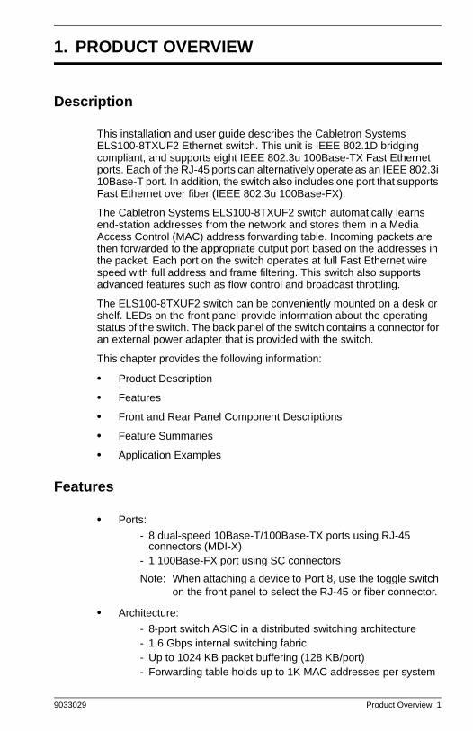
This installation and user guide describes the Cabletron Systems ELS100-8TXUF2 Ethernet switch. This unit is IEEE 802.1D bridging compliant, and supports eight IEEE 802.3u 100Base-TX Fast Ethernet ports. Each of the RJ-45 ports can alternatively operate as an IEEE 802.3i 10Base-T port. In addition, the switch also includes one port that supports Fast Ethernet over fiber (IEEE 802.3u 100Base-FX).
The Cabletron Systems ELS100-8TXUF2 switch automatically learns end-station addresses from the network and stores them in a Media Access Control (MAC) address forwarding table. Incoming packets are then forwarded to the appropriate output port based on the addresses in the packet. Each port on the switch operates at full Fast Ethernet wire speed with full address and frame filtering. This switch also supports advanced features such as flow control and broadcast throttling.
The ELS100-8TXUF2 switch can be conveniently mounted on a desk or shelf. LEDs on the front panel provide information about the operating status of the switch. The back panel of the switch contains a connector for an external power adapter that is provided with the switch.
This chapter provides the following information:
• Product Description
• Features
• Front and Rear Panel Component Descriptions
• Feature Summaries
• Application Examples
Features
• Ports:
- 8 dual-speed 10Base-T/100Base-TX ports using RJ-45 connectors (MDI-X)
- 1 100Base-FX port using SC connectors
Note: When attaching a device to Port 8, use the toggle switch on the front panel to select the RJ-45 or fiber connector.
• Architecture:
- 8-port switch ASIC in a distributed switching architecture- 1.6 Gbps internal switching fabric- Up to 1024 KB packet buffering (128 KB/port)- Forwarding table holds up to 1K MAC addresses per system
ELS100-8TXUF2.book Page 1 Friday, June 4, 1999 4:01 PM

2 Product Overview ELS100-8TXUF2
- IEEE 802.3u auto-negotiation for full/half duplex and 10/100 Mbps speed operation on all RJ-45 10/100 ports
- High performance store-and-forward switching
• Performance
Forwarding and Filtering: - at 10 Mbps, 14,880 packets-per-second (64 byte packets)- at 100 Mbps, 148,800 packets-per-second (64 byte packets)
• Traffic Management:
- Flow control per port: IEEE 802.3x frame-based for full duplex; back-pressure for half duplex
- Broadcast throttling for broadcast storm control
• LED Indicators:
- 10Base-T/100Base-TX Ethernet ports: Link, Speed, Collision- System: Power
Front Panel
Figure 1-1 shows the front panel of the Cabletron ELS100-8TXUF2. Table 1-1 defines the ELS100-8TXUF2 front panel components.
Figure 1-1. ELS100-8TXUF2 Front Panel
Table 1-1. Front Panel Components
Name Function
10Base-T/100Base-TXRJ-45 ports (Ports 1-8)*
Copper port using RJ-45 port connectors. These ports are wired MDI-X.
100Base-FX Fiber Ports (Port 8)*
Fiber ports using SC fiber connectors.
Ports LEDs Indicates Link, Speed and Collision information (see Table 1-2 for details).
Power LED Lights steady green to indicate power is supplied to the switch. Off indicates no power is supplied to the switch.
* When using Port 8, use the toggle switch on the front panel to select the RJ-45 con-nector or fiber connector.
ELS100-8TXUF2.book Page 2 Friday, June 4, 1999 4:01 PM
9033029 Product Overview 3
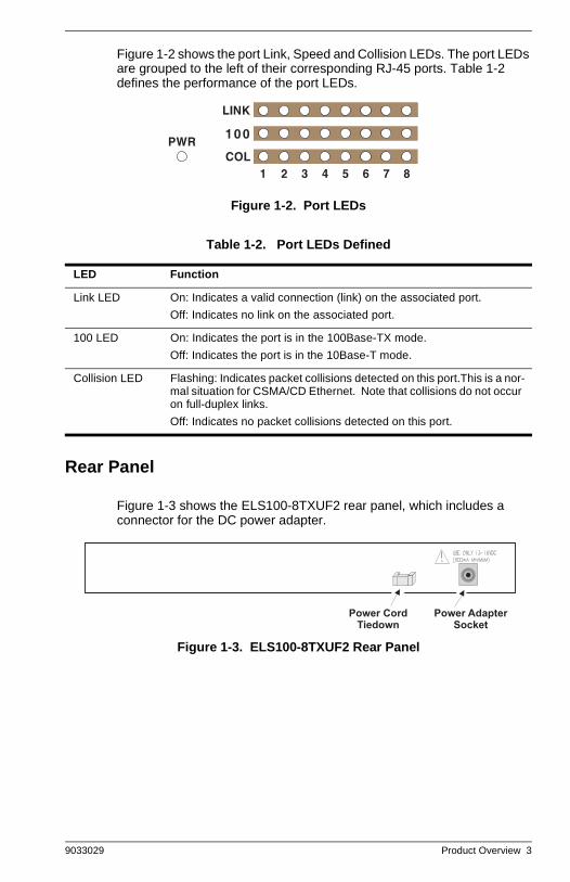
Figure 1-2 shows the port Link, Speed and Collision LEDs. The port LEDs are grouped to the left of their corresponding RJ-45 ports. Table 1-2 defines the performance of the port LEDs.
Figure 1-2. Port LEDs
Table 1-2. Port LEDs Defined
Rear Panel
Figure 1-3 shows the ELS100-8TXUF2 rear panel, which includes a connector for the DC power adapter.
Figure 1-3. ELS100-8TXUF2 Rear Panel
LED Function
Link LED On: Indicates a valid connection (link) on the associated port.
Off: Indicates no link on the associated port.
100 LED On: Indicates the port is in the 100Base-TX mode.
Off: Indicates the port is in the 10Base-T mode.
Collision LED Flashing: Indicates packet collisions detected on this port.This is a nor-mal situation for CSMA/CD Ethernet. Note that collisions do not occur on full-duplex links.
Off: Indicates no packet collisions detected on this port.
ELS100-8TXUF2.book Page 3 Friday, June 4, 1999 4:01 PM

4 Product Overview ELS100-8TXUF2
Feature Summaries
The following summaries provide a brief description of ELS100-8TXUF2 features in areas such as standards compliance, functionality, performance, and options.
IEEE 802.1D Bridge
The ELS100-8TXUF2 switch is fully compliant with IEEE 802.1D transparent bridging specifications. An aggregate address table containing 1K address entries is provided for learning, filtering, and forwarding. Addresses are automatically learned by the switch.
Frame Buffering and Frame Latency
The ELS100-8TXUF2 switch is a store-and-forward switching device. Each frame is copied into switch memory before being forwarded to another port. This method ensures that all forwarded frames conform to a standard Ethernet frame size and have a correct cyclic redundancy check (CRC) for data integrity. This switching method prevents bad frames from traversing the network and using up valuable network bandwidth, as with cut-through switching technology.
To minimize the possibility of dropping frames on congested ports, the ELS100-8TXUF2 switch provides 128 KB frame buffer per port. This buffer space is used to queue packets for transmission on congested networks. This is an additional advantage over cut-through switching technology, which drops packets immediately when experiencing collisions.
Auto-negotiation
Auto-negotiation is a process that permits the switch to automatically select the operational modes of its ports. Upon first being connected, the switch detects the speed of the network the port is connected to, either 10Mbps or 100Mbps, and the type of communication setting, half or full duplex. The port is then automatically set by the switch to operate in the proper mode without user intervention. It is not required that the network device being connected to the switch supports auto-negotiation as the ELS100-8TXUF2 switch automatically adjusts to the network device’s communication settings.
Broadcast Throttling
The ELS100-8TXUF2 switch has the capability to throttle (or limit) the flooding of packets through the switch. Broadcast, multicast, and unknown destination address unicast packets received by the switch are typically flooded to all ports on the switch. When the number of these types of packets being forwarded is large, the performance of the switch in forwarding packets of other types may suffer.
ELS100-8TXUF2.book Page 4 Friday, June 4, 1999 4:01 PM

9033029 Product Overview 5
A broadcast cutoff threshold rate has been set in the switch for the forwarding of broadcast and unknown destination address packets. If the cutoff rate is exceeded, further packets of these types are dropped. This capability helps to alleviate broadcast storms, a problem often encountered in Ethernet networks.
LEDs
The switch port LEDs provide a quick and accurate display of the status of switch connections. The port LEDs indicate link integrity, speed, and collisions (for half-duplex connections).
Full Duplex Mode
The full duplex mode of operation on a port can double the throughput of switch connections. This mode disables the collision detection portion of the Ethernet Carrier Sense Multiple Access with Collision Detection (CSMA/CD) protocol allowing for two-way traffic.
Flow Control
Flow control allows you to manage network traffic during congestion periods and to prevent the loss of packets when port buffer thresholds are exceeded. Flow control also serves to deny access to additional traffic that could add to a congestion condition. The ELS100-8TXUF2 switch supports flow control per the IEEE 802.3x standard. See Appendix C “Flow Control” for more information on this feature.
Spanning Tree
This product is intended to be used as an end-switch and does not support spanning tree. There is no loop detection. The user is cautioned to understand and avoid configurations that can create a loop.
Application Examples
The exploding popularity of the Internet and of corporate intranets, as well as new, high-bandwidth desktop applications are driving the demand for Fast Ethernet. The increase in multimedia traffic and the need to support legacy protocols alongside new, data intensive applications is driving the need for network segmentation and traffic prioritization.
The ELS100-8TXUF2 switch is ideal for meeting the needs of today’s high performance networks. The switch’s low cost makes it attractive and affordable for dedicated 10/100Mbps connections to the desktop.
The following sections illustrate the ELS100-8TXUF2 switch employed in application examples:
• Client/Server Network
• Local Backbone
ELS100-8TXUF2.book Page 5 Friday, June 4, 1999 4:01 PM

6 Product Overview ELS100-8TXUF2
Client/Server Network Application
To improve workstation performance in a client/server environment, the ELS100-8TXUF2 switch can be configured to provide 200 Mbps full duplex Fast Ethernet connections to servers by connecting each to a dedicated switch port (Figure 1-4). Users can be accommodated through connections to hubs, both at 10Mbps and 100Mbps speeds, through 10Mbps switches with 100Mbps uplinks, or through direct connections. The fiber uplink is available to connect the switch to a remote location, such as another building floor or a separate building.
The ELS100-8TXUF2 switch can be used in a local backbone application, connecting network segments together and providing file-server access. Workgroup hubs are provided with a single connection to the switch while servers are put on dedicated 100 Mbps ports. Routers and other networking devices can connect off of the switched backbone as well. The fiber uplink is available to connect the switch to a remote location, such as another building floor or a separate building.
Figure 1-4. Client/Server Network Application
ELS100-8TXUF2.book Page 6 Friday, June 4, 1999 4:01 PM

9033029 Installation 7
2. INSTALLATION
Inspecting Your Shipment
When you receive the shipment of your switch, check the package contents and make sure you have the following items:
• ELS100-8TXUF2 Fast Ethernet switch
• Mounting velcro
• Rubber feet
• Power adapter
• This document
Site Requirements
Before you install the switch, make sure the site meets the following requirements:
• Mounting
Provide a flat table, wall or shelf surface.
• Power source
Provide a power source within six feet (1.8 m) of the installation loca-tion. This source must provide 100 VAC to 240 VAC, and 50 Hz to 60 Hz power, with a 100 VA minimum. Power specifications for the switch are shown in Appendix A, “Technical Specifications.”
• Environmental
Install the ELS100-8TXUF2 switch in a dry area, with adequate air circulation. Avoid placing the switch in direct sunlight or near other heat sources, such as hot-air vents. For temperature and humidity specifications, see Appendix A, “Technical Specifications.”
• Ventilation
Do not restrict airflow by covering or obstructing air inlets on the side of the switch.
ELS100-8TXUF2.book Page 7 Friday, June 4, 1999 4:01 PM

8 Installation ELS100-8TXUF2
Mounting the Switch on a Table or Shelf
First attach the rubber feet to the indentations on the bottom of the switch. Then mount the switch on a table or shelf in a position that allows access to the front panel RJ-45 ports, visibility of the port LEDs, and access to the power cord. Make sure that the mounting surface can safely support the switch and that there is adequate space around the switch for ventilation and cooling.
The rubber feet improve the switch’s grip on the mounting surface, and provide ventilation between switches when stacked together.
ELS100-8TXUF2.book Page 8 Friday, June 4, 1999 4:01 PM

9033029 Installation 9
MMounting the Switch on a Wall
The module ships with one (1) velcro strip. The velcro strip is used to attach the switch to the wall.
Figure 2-1 illustrates two recommended orientations for wall mounting the switch. This figure also shows where to the position velcro on the switch. To attach velcro do the following:
1. Place the switch on a flat surface with the Cabletron logo on the left and the 100Base-FX ports on the right.
2. Attach the velcro to the center of the switch using the supplied 2 x 4 inch strip of velcro.
3. Position the switch on a wall surface that can safely support the switch.
Figure 2-1. Mounting the Switch on a Wall
Do not attach rubber feet to the switch when mounting the switch to the wall with velcro.
ELS100-8TXUF2.book Page 9 Friday, June 4, 1999 4:01 PM

10 Installation ELS100-8TXUF2
Powering the Switch
To supply power to the switch, do the following:
1. Connect the power adapter to the switch and to a grounded three-prong wall outlet (Figure 2-2). Secure the power cord to the tiedown bracket on the back of the switch to prevent it from being accidentally disconnected from the switch. See Appendix A, “Power Adapter Set Requirements,” for more information regarding specific international power adapter requirements.
Figure 2-2. Connecting the Power Cord to the Switch
2. Check the Power LED.
The Power LED lights green (see Figure 1-1). If it does not, check to make sure that the power cord is plugged in correctly and that the power source is good.
Power-Up Verification
When you connect the power cord, the switch conducts a series of hardware and software tests to verify correct operation.
ELS100-8TXUF2.book Page 10 Friday, June 4, 1999 4:01 PM
9033029 Installation 11
Network Cable Requirements
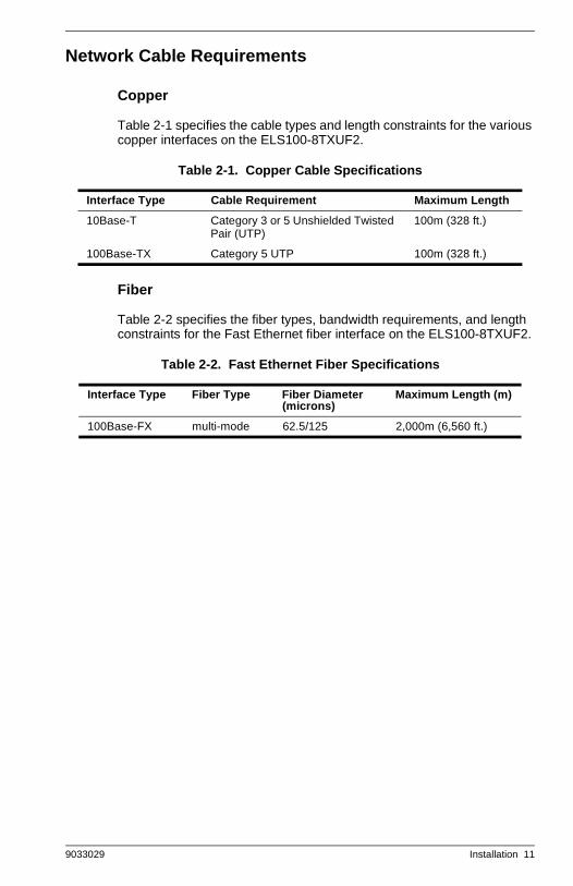
Copper
Table 2-1 specifies the cable types and length constraints for the various copper interfaces on the ELS100-8TXUF2.
Table 2-1. Copper Cable Specifications
Fiber
Table 2-2 specifies the fiber types, bandwidth requirements, and length constraints for the Fast Ethernet fiber interface on the ELS100-8TXUF2.
Table 2-2. Fast Ethernet Fiber Specifications
Interface Type Cable Requirement Maximum Length
10Base-T Category 3 or 5 Unshielded Twisted Pair (UTP)
100m (328 ft.)
100Base-TX Category 5 UTP 100m (328 ft.)
Interface Type Fiber Type Fiber Diameter (microns)
Maximum Length (m)
100Base-FX multi-mode 62.5/125 2,000m (6,560 ft.)
ELS100-8TXUF2.book Page 11 Friday, June 4, 1999 4:01 PM

12 Installation ELS100-8TXUF2
10Base-T/100Base-TX Ports
The 10Base-T/100Base-TX ports use RJ-45 connectors. Figure 2-3 shows an RJ-45 connector being inserted into a port.
Figure 2-3. Inserting an RJ-45 Connector into a Port
The 10Base-T/100Base-TX ports interface to UTP cabling for connection to 10Base-T or 100Base-TX network segments or end-stations. These UTP connections meet the requirements of ISO 8877, specified by 10Base-T, Section 14 of the IEEE 802.3 specification. The ports are wired with the MDI-X function implemented. Workstations or servers can be connected to the ELS100-8TXUF2 switch using standard straight-through wired cables.
For connections to hubs or other switches, a crossover cable may be necessary (refer to the “MDI/MDI-X Crossover Cable Wiring” section in Appendix A). See Table A-2 for 10Base-T/100Base-TX connector pin assignments.
ELS100-8TXUF2.book Page 12 Friday, June 4, 1999 4:01 PM
9033029 Installation 13
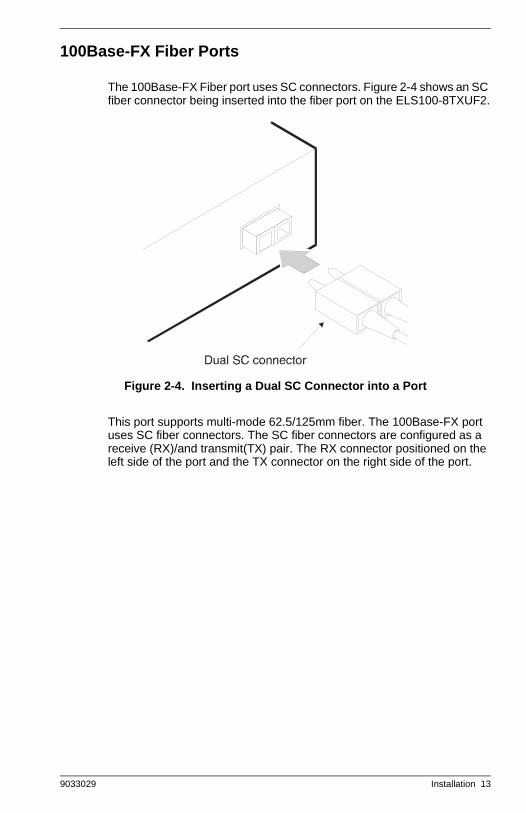
100Base-FX Fiber Ports
The 100Base-FX Fiber port uses SC connectors. Figure 2-4 shows an SC fiber connector being inserted into the fiber port on the ELS100-8TXUF2.
Figure 2-4. Inserting a Dual SC Connector into a Port
This port supports multi-mode 62.5/125mm fiber. The 100Base-FX port uses SC fiber connectors. The SC fiber connectors are configured as a receive (RX)/and transmit(TX) pair. The RX connector positioned on the left side of the port and the TX connector on the right side of the port.
ELS100-8TXUF2.book Page 13 Friday, June 4, 1999 4:01 PM

14 Installation ELS100-8TXUF2
ELS100-8TXUF2.book Page 14 Friday, June 4, 1999 4:01 PM
9033029 Technical Specifications 15
APPENDIX A. TECHNICAL SPECIFICATIONS
General
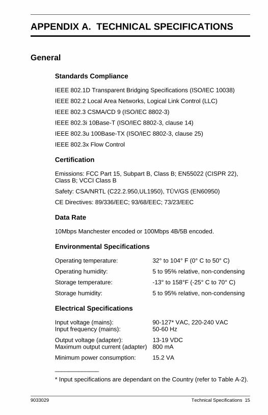
Standards Compliance
IEEE 802.1D Transparent Bridging Specifications (ISO/IEC 10038)
IEEE 802.2 Local Area Networks, Logical Link Control (LLC)
IEEE 802.3 CSMA/CD 9 (ISO/IEC 8802-3)
IEEE 802.3i 10Base-T (ISO/IEC 8802-3, clause 14)
IEEE 802.3u 100Base-TX (ISO/IEC 8802-3, clause 25)
IEEE 802.3x Flow Control
Certification
Emissions: FCC Part 15, Subpart B, Class B; EN55022 (CISPR 22), Class B; VCCI Class B
Safety: CSA/NRTL (C22.2.950,UL1950), TÜV/GS (EN60950)
CE Directives: 89/336/EEC; 93/68/EEC; 73/23/EEC
Data Rate
10Mbps Manchester encoded or 100Mbps 4B/5B encoded.
Environmental Specifications
Operating temperature: 32° to 104° F (0° C to 50° C)
Operating humidity: 5 to 95% relative, non-condensing
Storage temperature: -13° to 158°F (-25° C to 70° C)
Storage humidity: 5 to 95% relative, non-condensing
Electrical Specifications
Input voltage (mains): 90-127* VAC, 220-240 VACInput frequency (mains): 50-60 Hz
Output voltage (adapter): 13-19 VDCMaximum output current (adapter) 800 mA
Minimum power consumption: 15.2 VA
_____________
* Input specifications are dependant on the Country (refer to Table A-2).
ELS100-8TXUF2.book Page 15 Friday, June 4, 1999 4:01 PM
16 Technical Specifications ELS100-8TXUF2
Physical
Height: 1.46 in. (3.7 cm)
Length: 4.65 in. (11.6 cm)
Width: 9.88 in. (24.9 cm)
Weight: 1.8 lb. (0.815 kg)
Memory
Packet Buffer Memory: 128 KB per port
Port Specifications
10Base-T and 100Base-TX Ports
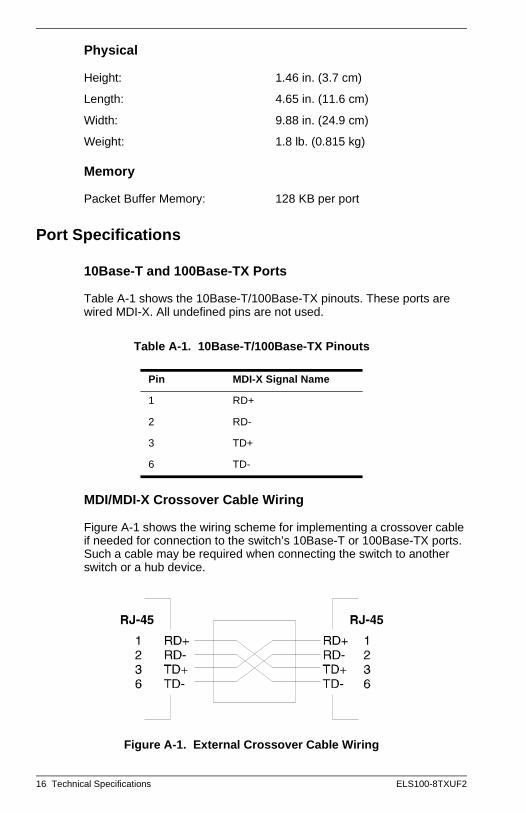
Table A-1 shows the 10Base-T/100Base-TX pinouts. These ports are wired MDI-X. All undefined pins are not used.
Table A-1. 10Base-T/100Base-TX Pinouts
MDI/MDI-X Crossover Cable Wiring
Figure A-1 shows the wiring scheme for implementing a crossover cable if needed for connection to the switch’s 10Base-T or 100Base-TX ports. Such a cable may be required when connecting the switch to another switch or a hub device.
Figure A-1. External Crossover Cable Wiring
Pin MDI-X Signal Name
1 RD+
2 RD-
3 TD+
6 TD-
ELS100-8TXUF2.book Page 16 Friday, June 4, 1999 4:01 PM

9033029 Technical Specifications 17
Power Adapter Requirements
Table A-2 shows the power adapter requirements.
Table A-2. Power Adapter Requirements
Country Adapter P/N Input Specifications* Output Specifications*
USA: 0950-3274 110-127 VAC, 60Hz 19 VDC, 800 mA
Japan: 0950-3267 90-110 VAC, 50 Hz 19 VDC, 800mA
Australia: 0950-3269 230-240 VAC, 50 Hz 19 VDC, 800mA
UK: 0950-3270 220-240 VAC, 50 Hz 19 VDC, 800mA
Europe: T4190800SE 220-240 VAC, 50Hz 19 VDC, 800 mA
* Specifications are shown on the adapter label.
ELS100-8TXUF2.book Page 17 Friday, June 4, 1999 4:01 PM

18 Technical Specifications ELS100-8TXUF2
ELS100-8TXUF2.book Page 18 Friday, June 4, 1999 4:01 PM

9033029 Flow Control 19
APPENDIX B. FLOW CONTROL
Flow control is a mechanism that controls the flow of data in both directions to prevent data loss, buffer deadlock, overload conditions and minimizing communications overhead during transmission. Figure B-1 illustrates flow control for both half and full duplex applications.
Figure B-1. Flow Control for Full and Half Duplex Applications
Each port of the switch has a transmit queue which buffers frames to be sent out on that port. In this example, large amounts of data are being sent from Workstation A (connected to port X) and other ports on the switch to Workstation B (connected to port Y).The buffer on port Y starts filling up with data until it reaches a pre-determined threshold. The packet which causes the threshold to be exceeded triggers the Flow Control function on the port from which the packet entered the switch, in this case port X.
Since port X is configured with Flow Control set to Enabled, the switch responds by initiating a pause frame (full duplex applications) or back-pressure mechanism (half duplex applications). The pause frame causes Workstation A to stop sending packets. After a certain amount of time has elapsed, determined by a value in the pause frame, Workstation A will resume sending data. Similarly, the back-pressure mechanism forces Workstation A to stop sending packets by inducing collisions on port X. Note that for the full duplex pause frame mechanism to work, the device connected to the switch port must also support IEEE 802.3x flow control.
The pause frame flow control mechanism supported by the ELS100-8TXUF2 switch conforms with the IEEE 802.3x specification for full duplex flow control.
ELS100-8TXUF2.book Page 19 Friday, June 4, 1999 4:01 PM

20 Flow Control ELS100-8TXUF2
ELS100-8TXUF2.book Page 20 Friday, June 4, 1999 4:01 PM

9033029 Acronyms and Abbreviations 21
APPENDIX C.ACRONYMS AND ABBREVIATIONS
Term Definition
10Base-T 10Mbps twisted-pair Ethernet
100Base-TX 100Mbps twisted-pair Fast Ethernet
100Base-FX 100Mbps fiber optic Fast Ethernet
ANSI American National Standards Institute
ASIC Application Specific Integrated Circuit
CAT5 Category 5
CSMA/CD Carrier Sense Multiple Access/Collision Detection
IEEE Institute of Electrical and Electronics Engineers
LAN Local Area Network
MAC Media Access Control
LED Light Emitting Diode
MDI Media Device Interface
MDI-X Media Device Interface-crossover cable wiring
RFC Request for Comment
UTP Unshielded Twisted Pair
end-switch A switch that terminates a branch. Also known as a leaf switch.
ELS100-8TXUF2.book Page 21 Friday, June 4, 1999 4:01 PM

22 Acronyms and Abbreviations ELS100-8TXFU2
ELS100-8TXUF2.book Page 22 Friday, June 4, 1999 4:01 PM

9033029 Index 23
INDEX
10Base-T/100Base-TXPinouts, 16Ports, 12
802.1D, 4, 15802.2, 15802.3, 12, 15802.3i, 15802.3u, 15802.3x, 2, 15, 19
Aarchitecture, 1
Bbroadcast throttling, 4
Ccertification, 15client/server network application, 6connecting network cables, 11crossover cable, 12cut-through, 4
DData Rate, 15
EElectrical Specifications, 15Environmental Specifications, 15
FFiber Optic Cable
multi-mode, 11flow control, 5, 19
802.3x, 19front panel, 2front panel components, 2
Iinspecting your shipment, 7
LLEDs, 3
MMDI-X, 12Memory, 16mounting the switch
table or shelf, 8wall, 9
Pperformance, 2Physical Specifications, 16port LEDs, 3
defined, 3Port Specifications, 16Power Adapter Requirements, 17power cord, 10power LED, 2
defined, 2power source, 7powering the switch, 10
Rrear panel, 3RJ-45 connectors, 12
SSC fiber connector, 13site requirements, 7Spanning Tree, 5Standards Compliance
IEEE, 15store-and-forward, 4
UUnshielded Twisted Pair (UTP), 11
VVentilation, 7
Wworkgroup hubs, 6
ELS100-8TXUF2.book Page 23 Friday, June 4, 1999 4:01 PM

24 Index ELS100-8TXUF2
ELS100-8TXUF2.book Page 24 Friday, June 4, 1999 4:01 PM