smart guiding glasses for visually impaired people in ... · 0000-0003-4322-6598 1 abstract—to...
TRANSCRIPT

0000-0003-4322-6598 1
Abstract—To overcome the travelling difficulty for the visually
impaired group, this paper presents a novel ETA (Electronic
Travel Aids)-smart guiding device in the shape of a pair of
eyeglasses for giving these people guidance efficiently and safely.
Different from existing works, a novel multi-sensor fusion based
obstacle avoiding algorithm is proposed, which utilizes both the
depth sensor and ultrasonic sensor to solve the problems of
detecting small obstacles, and transparent obstacles, e.g. the
French door. For totally blind people, three kinds of auditory cues
were developed to inform the direction where they can go ahead.
Whereas for weak sighted people, visual enhancement which
leverages the AR (Augment Reality) technique and integrates the
traversable direction is adopted. The prototype consisting of a
pair of display glasses and several low-cost sensors is developed,
and its efficiency and accuracy were tested by a number of users.
The experimental results show that the smart guiding glasses can
effectively improve the user’s travelling experience in complicated
indoor environment. Thus it serves as a consumer device for
helping the visually impaired people to travel safely.
Index Terms—AR, depth sensor, ETA, sensor fusion, vision
enhancement
I. INTRODUCTION
CCORDING to the official statistics from World Health
Organization, there are about 285 million visually
impaired persons in the world up to the year of 2011: about 39
million are completely blind and 246 million have weak sight
[1]. This number will increase rapidly as the baby boomer
generation ages [2]. These visually impaired people have great
difficulty in perceiving and interacting with the surroundings,
especially those which are unfamiliar. Fortunately, there are
some navigation systems or tools available for visually
impaired individuals. Traditionally, most people rely on the
white cane for local navigation, constantly swaying it in front
for obstacle detection [3]. However, they cannot adequately
perceive all the necessary information such as volume or
distance, etc. [4]. Comparably, ETA (Electronic Travel Aid)
can provide more information about the surroundings by
This work was supported by the CloudMinds Technologies Inc.
Jinqiang Bai is with Beihang University, Beijing, 10083, China (e-mail: [email protected]).
Shiguo Lian, Zhaoxiang Liu, Kai Wang are all with AI Department,
CloudMinds Technologies Inc., Beijing, 100102, China (e-mail: { scott.lian, robin.liu, kai.wang }@cloudminds.com).
Dijun Liu is with DT-LinkTech Inc., Beijing, 10083, China (e-mail:
integrating multiple electronic sensors and have proved to be
effective on improving the visually impaired person’s daily life
[4], and the device presented in this work belongs to such
category.
The RGB-D (Red, Green, Blue and Depth) sensor based
ETA [5], [6] can detect obstacles more easily and precisely than
other sensor (e.g. ultrasonic sensor, mono-camera, etc.) based
scheme. However, a drawback of the depth sensor is that it has
a limited working range in measuring the distance of the
obstacle and cannot work well in the face of transparent objects,
such as glass, French window, French door, etc. To overcome
this limitation, a multi-sensor fusion based obstacle avoiding
algorithm, which utilizes both the depth sensor and the
ultrasonic sensor, is proposed in this work.
The totally blind people can be informed through auditory
and/or tactile sensor [7]. Tactile feedback does not block the
auditory sense, which is the most important perceptual input
source. However, such an approach has the drawbacks of high
power consumption and large size, which is not suitable for
wearable ETA (like the glasses proposed in this work). Thus,
sound or synthetic voice is the option for the first case. Some
sound feedback based ETAs map the processed RGB image
and/or depth image to acoustic patterns [8] or semantic speech
[9] for helping the blind to perceive the surroundings. But, the
blind still needs to understand the feedback sound and decide
where they can go ahead by himself. Thus, such systems are
hard to ensure the blind making a right decision according to
the feedback sound. Focusing on the above problem, three
kinds of auditory cues, which is converted from the traversable
direction (produced by the multi-sensor fusion based obstacle
avoiding algorithm) were developed in this paper for directly
guiding the user where to go.
Since the weak sighted people have some degree of visual
perception, and vision can provide more information than other
senses, e.g. touch and hearing, the visual enhancement, which
uses the popular AR (Augmented Reality) [10], [11] technique
for displaying the surroundings and the feasible direction on the
eyeglasses, is proposed to help the users to avoid the obstacle.
The rest of the paper is organized as follows. Section II
reviews the related works involved in guiding the visually
impaired people. The proposed smart guiding glasses are
presented in Section III. Section IV shows some experimental
results, and demonstrates the effectiveness and robustness of
the proposed system. Finally, some conclusions are drawn in
Section V.
Smart Guiding Glasses for Visually Impaired
People in Indoor Environment
Jinqiang Bai, Shiguo Lian, Member, IEEE, Zhaoxiang Liu, Kai Wang, Dijun Liu
A

0000-0003-4322-6598 2
II. RELATED WORK
As this work focuses on the obstacle avoidance and the
guiding information feedback, the related work with respect to
such two fields are reviewed in this section.
A. Obstacle Avoidance
There exist a vast literature on obstacle detection and
avoidance. According to the sensor type, the obstacle
avoidance method can be categorized as: ultrasonic sensor
based method [12], laser scanner based method [13], and
camera based method [5], [6], [14]. Ultrasonic sensor based
method can measure the distance of obstacle and compare it
with the given distance threshold for deciding whether to go
ahead, but it cannot determine the exact direction of going
forward, and may suffer from interference problems with the
sensors themselves if ultrasonic radar (ultrasonic sensor array)
is used, or other signals in indoor environment. Although laser
scanner based method is widely used in mobile robot
navigation for their high precision and resolution, the laser
scanner is expensive, heavy, and with high power consumption,
so it is not suitable for wearable navigation system. As for
camera based method, there are many methods based on
different cameras, such as mono-camera, stereo-camera, and
RGB-D camera. Based on the mono-camera, some methods
process RGB image to detect obstacles by e.g., floor
segmentation [15], [16], deformable grid based obstacle
detection [8], etc. However, these methods cost so much
computation that they are not satisfied for real-time
applications, and hard to measure the distance of the obstacle.
To measure the distance, some stereo-camera based methods
are proposed. For example, the method [17] uses local window
based matching algorithms for estimating the distance of
obstacles, and the method [18] uses genetic algorithm to
generate dense disparity maps that can also estimate the
distance of obstacles. However, these methods will fail under
low-texture or low-light scenarios, which cannot ensure the
secure navigation. Recently, RGB-D cameras have been widely
used in many applications [5], [14], [19]-[21] for their low cost,
good miniaturization and ability of providing wealthy
information. The RGB-D cameras provide both dense range
information from active sensing and color information from
passive sensor such as standard camera. The RGB-D camera
based method [5] combines range information with color
information to extend the floor segmentation to the entire scene
for detecting the obstacles in detail. The one in [14] builds a 3D
(3 Dimensional) voxel map of the environment and analyzes
3D traversability for obstacle avoidance. But these methods are
constrained to non-transparent objects scenarios due to the
imperfection of the depth camera.
B. Guiding Information Feedback
There are three main techniques for providing guiding
information to visually impaired people [22], i.e., haptic, audio
and visual. Haptic feedback based systems often use vibrators
on a belt [7], helmet [23] or in a backpack [14]. Although they
have far less interference with sensing the environment, they
are hard to represent complicated information and require more
training and concentration. Audio feedback based systems
utilize acoustic patterns [8], [9], semantic speech [24], different
intensities sound [25] or spatially localized auditory cues [26].
The method in [8], [9] directly maps the processed RGB image
to acoustic patterns for helping the blind to perceive the
surroundings. The method in [24] maps the depth image to
semantic speech for telling the blind some information about
the obstacles. The method in [25] maps the depth image to
different intensities sound for representing obstacles in
different distance. The method in [26] maps the depth image to
spatially localized auditory cues for expressing the 3D
information of the surroundings. However, the user will
misunderstand these auditory cues under noisy or complicated
environment. Visual feedback based systems can be used for
the partially sighted individuals due to its ability of providing
more detailed information than haptic or audio feedback based
systems. The method in [27] maps the distance of the obstacle
to brightness on LED (Light Emitting Diode) display as a visual
enhancement method to help the users more easily to notice the
obstacle. But, the LED display only shows the large obstacle
due to its low resolution.
In this paper, a novel multi-sensor fusion based obstacle
avoiding algorithm is proposed to overcome the above
limitations, which utilizes both the depth sensor and ultrasonic
sensor to find the optimal traversable direction. The output
traversable direction is then converted to three kinds of auditory
cues in order to select an optimal one under different scenarios,
and integrated in the AR technique based visual enhancement
for guiding the visually impaired people.
III. THE PROPOSED FRAMEWORK
A. The Hardware System
The proposed system includes a depth camera for acquiring
the depth information of the surroundings, an ultrasonic
rangefinder consisting of an ultrasonic sensor and a MCU
(Microprogrammed Control Unit) for measuring the obstacle
distance, an embedded CPU (Central Processing Unit) board
acting as main processing module, which does such operations
as depth image processing, data fusion, AR rendering, guiding
sound synthesis, etc., a pair of AR glasses to display the visual
enhancement information and an earphone to play the guiding
sound. The hardware configuration of the proposed system is
illustrated in Fig. 1, and the initial prototype of the system is
shown in Fig. 2.
Fig. 1. The hardware configuration of the proposed system.
0000-0003-4322-6598 3
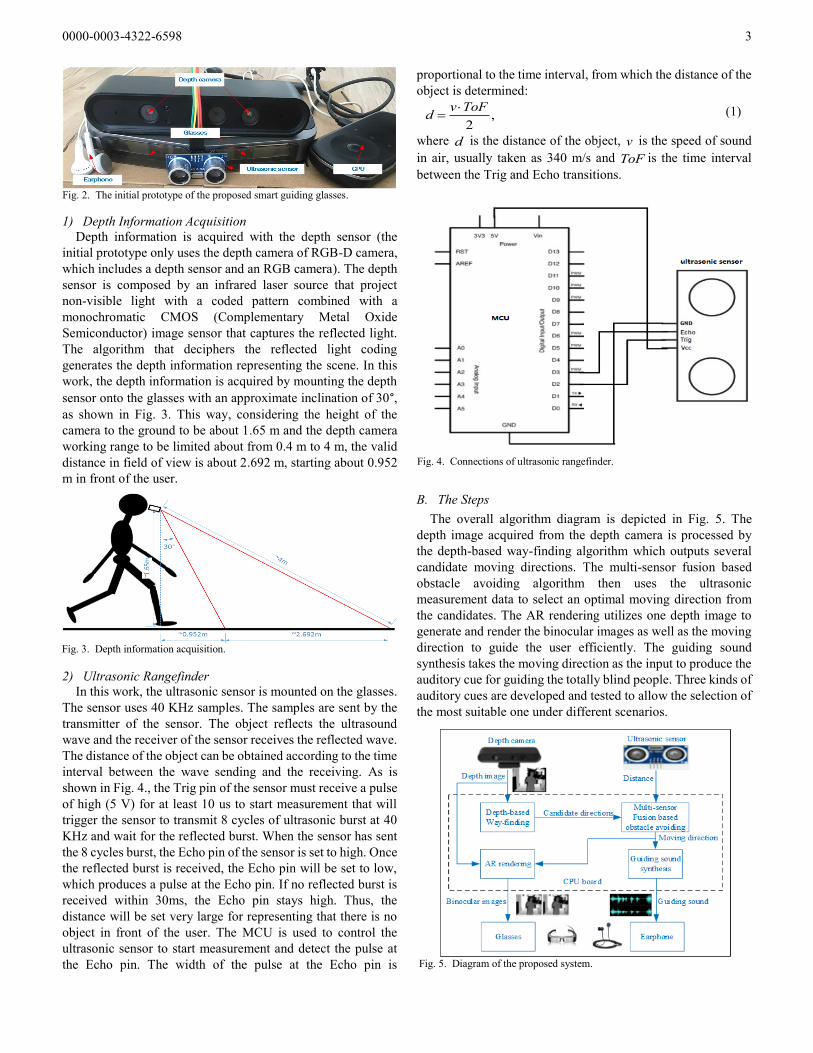
1) Depth Information Acquisition
Depth information is acquired with the depth sensor (the
initial prototype only uses the depth camera of RGB-D camera,
which includes a depth sensor and an RGB camera). The depth
sensor is composed by an infrared laser source that project
non-visible light with a coded pattern combined with a
monochromatic CMOS (Complementary Metal Oxide
Semiconductor) image sensor that captures the reflected light.
The algorithm that deciphers the reflected light coding
generates the depth information representing the scene. In this
work, the depth information is acquired by mounting the depth
sensor onto the glasses with an approximate inclination of 30°, as shown in Fig. 3. This way, considering the height of the
camera to the ground to be about 1.65 m and the depth camera
working range to be limited about from 0.4 m to 4 m, the valid
distance in field of view is about 2.692 m, starting about 0.952
m in front of the user.
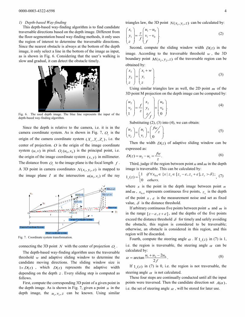
2) Ultrasonic Rangefinder
In this work, the ultrasonic sensor is mounted on the glasses.
The sensor uses 40 KHz samples. The samples are sent by the
transmitter of the sensor. The object reflects the ultrasound
wave and the receiver of the sensor receives the reflected wave.
The distance of the object can be obtained according to the time
interval between the wave sending and the receiving. As is
shown in Fig. 4., the Trig pin of the sensor must receive a pulse
of high (5 V) for at least 10 us to start measurement that will
trigger the sensor to transmit 8 cycles of ultrasonic burst at 40
KHz and wait for the reflected burst. When the sensor has sent
the 8 cycles burst, the Echo pin of the sensor is set to high. Once
the reflected burst is received, the Echo pin will be set to low,
which produces a pulse at the Echo pin. If no reflected burst is
received within 30ms, the Echo pin stays high. Thus, the
distance will be set very large for representing that there is no
object in front of the user. The MCU is used to control the
ultrasonic sensor to start measurement and detect the pulse at
the Echo pin. The width of the pulse at the Echo pin is
proportional to the time interval, from which the distance of the
object is determined:
,2
v ToFd
(1)
where d is the distance of the object, v is the speed of sound
in air, usually taken as 340 m/s and ToF is the time interval
between the Trig and Echo transitions.
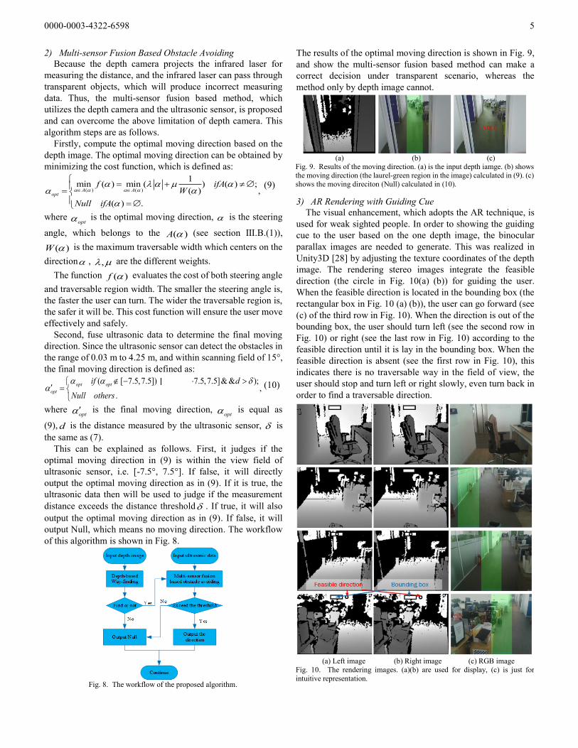
B. The Steps
The overall algorithm diagram is depicted in Fig. 5. The
depth image acquired from the depth camera is processed by
the depth-based way-finding algorithm which outputs several
candidate moving directions. The multi-sensor fusion based
obstacle avoiding algorithm then uses the ultrasonic
measurement data to select an optimal moving direction from
the candidates. The AR rendering utilizes one depth image to
generate and render the binocular images as well as the moving
direction to guide the user efficiently. The guiding sound
synthesis takes the moving direction as the input to produce the
auditory cue for guiding the totally blind people. Three kinds of
auditory cues are developed and tested to allow the selection of
the most suitable one under different scenarios.
Fig. 3. Depth information acquisition.
Fig. 2. The initial prototype of the proposed smart guiding glasses.
Fig. 4. Connections of ultrasonic rangefinder.
Fig. 5. Diagram of the proposed system.
0000-0003-4322-6598 4
1) Depth-based Way-finding
This depth-based way-finding algorithm is to find candidate
traversable directions based on the depth image. Different from
the floor-segmentation based way-finding methods, it only uses
the region of interest to determine the traversable directions.
Since the nearest obstacle is always at the bottom of the depth
image, it only select a line in the bottom of the image as input,
as is shown in Fig. 6. Considering that the user’s walking is
slow and gradual, it can detect the obstacle timely.
Since the depth is relative to the camera, i.e. it is in the
camera coordinate system. As is shown in Fig. 7, cO is the
origin of the camera coordinate system ( , , )c c cX Y Z , i.e. the
center of projection. O is the origin of the image coordinate
system ( , )u v in pixel. 0 0( , )IO u v is the principal point, i.e.
the origin of the image coordinate system ( , )x y in millimeter.
The distance from cO to the image plane is the focal length f .
A 3D point in camera coordinates 1 1( , , )N x y z is mapped to
the image plane I at the intersection 1 1( , )n u v of the ray
connecting the 3D point N with the center of projection cO .
The depth-based way-finding algorithm uses the traversable
threshold w and adaptive sliding window to determine the
candidate moving directions. The sliding window size is
1 ( )D z , which ( )D z represents the adaptive width
depending on the depth z . Every sliding step is computed as
follows.
First, compute the corresponding 3D point of a given point in
the depth image. As is shown in Fig. 7, given a point n in the
depth image, the 1 1, ,u v z can be known. Using similar
triangles law, the 3D point 1 1( , , )N x y z can be calculated by:
1 01
1 1 0 .
u uxz
y v vf
z f
(2)
Second, compute the sliding window width ( )D z in the
image. According to the traversable threshold w , the 3D
boundary point 2 2( , , )M x y z of the traversable region can be
obtained by:
2 1
2 1 .
x x w
y y
z z
(3)
Using similar triangles law as well, the 2D point m of the
3D point M projection on the depth image can be computed by:
02 2
2 2 0 .
1 0
uu xf
v y vz
zf
(4)
Substituting (2), (3) into (4), we can obtain:
2 1
2 1
+ .0
fwu uz
v v
(5)
Then the width ( )D z of adaptive sliding window can be
expressed as:
2 1( ) .fw
D z u uz
(6)
Third, judge if the region between point n and m in the depth
image is traversable. This can be calculated by:
0:41 { | [ , ], };1 ( ) ,
0 .
x x x x
x
if x x z z z zz
others
(7)
where x is the point in the depth image between point n
and m , 0 4x :
represents continuous five points, xz is the depth
of the point x , is the measurement noise and set as fixed
value, is the distance threshold.
If arbitrary continuous five points between point n and m is
in the range [ , ]z z , and the depths of the five points
exceed the distance threshold for timely and safely avoiding
the obstacle, this region is considered to be traversable;
otherwise, an obstacle is considered in this region, and this
region will be discarded.
Fourth, compute the steering angle . If 1 ( )x z in (7) is 1,
i.e. the region is traversable, the steering angle can be
calculated by:
1 2 02arctan .
2
u u u
f
(8)
If 1 ( )x z in (7) is 0, i.e. the region is not traversable, the
steering angle is not calculated.
These four steps are continually conducted until all the input
points were traversed. Then the candidate direction set ( )A ,
i.e. the set of steering angle , will be stored for later use.
Fig. 6. The used depth image. The blue line represents the input of the depth-based way-finding algorithm.
Fig. 7. Coordinate system transformation.
0000-0003-4322-6598 5
2) Multi-sensor Fusion Based Obstacle Avoiding
Because the depth camera projects the infrared laser for
measuring the distance, and the infrared laser can pass through
transparent objects, which will produce incorrect measuring
data. Thus, the multi-sensor fusion based method, which
utilizes the depth camera and the ultrasonic sensor, is proposed
and can overcome the above limitation of depth camera. This
algorithm steps are as follows.
Firstly, compute the optimal moving direction based on the
depth image. The optimal moving direction can be obtained by
minimizing the cost function, which is defined as:
( ) ( )
1min ( ) min ( ) ( ) ;
( ) ,
( ) .
A Aopt
f ifAW
Null ifA
(9)
where opt is the optimal moving direction, is the steering
angle, which belongs to the ( )A (see section Ⅲ.B.(1)),
( )W is the maximum traversable width which centers on the
direction , , are the different weights.
The function ( )f evaluates the cost of both steering angle
and traversable region width. The smaller the steering angle is,
the faster the user can turn. The wider the traversable region is,
the safer it will be. This cost function will ensure the user move
effectively and safely.
Second, fuse ultrasonic data to determine the final moving
direction. Since the ultrasonic sensor can detect the obstacles in
the range of 0.03 m to 4.25 m, and within scanning field of 15°,
the final moving direction is defined as:
( [ 7.5,7.5]) ( [ 7.5,7.5]& & );,
.
opt opt opt
opt
if d
Null others
(10)
where opt is the final moving direction,
opt is equal as
(9), d is the distance measured by the ultrasonic sensor, is
the same as (7).
This can be explained as follows. First, it judges if the
optimal moving direction in (9) is within the view field of
ultrasonic sensor, i.e. [-7.5°, 7.5°]. If false, it will directly
output the optimal moving direction as in (9). If it is true, the
ultrasonic data then will be used to judge if the measurement
distance exceeds the distance threshold . If true, it will also
output the optimal moving direction as in (9). If false, it will
output Null, which means no moving direction. The workflow
of this algorithm is shown in Fig. 8.
The results of the optimal moving direction is shown in Fig. 9,
and show the multi-sensor fusion based method can make a
correct decision under transparent scenario, whereas the
method only by depth image cannot.
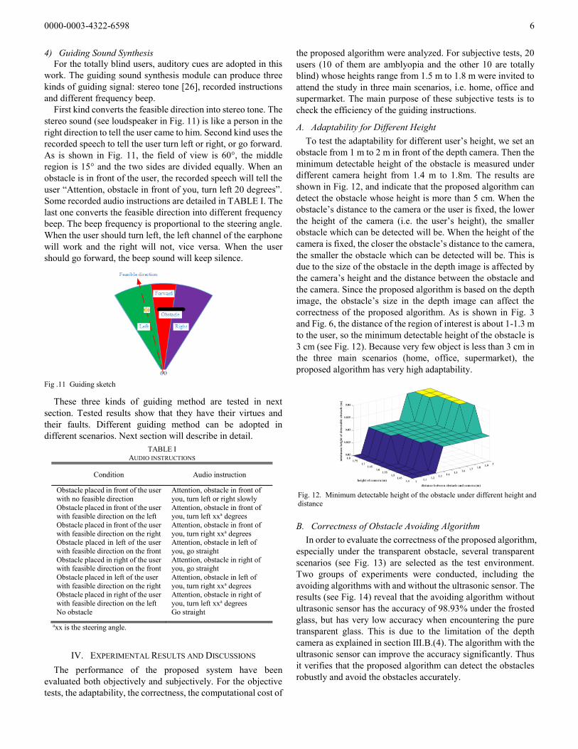
3) AR Rendering with Guiding Cue
The visual enhancement, which adopts the AR technique, is
used for weak sighted people. In order to showing the guiding
cue to the user based on the one depth image, the binocular
parallax images are needed to generate. This was realized in
Unity3D [28] by adjusting the texture coordinates of the depth
image. The rendering stereo images integrate the feasible
direction (the circle in Fig. 10(a) (b)) for guiding the user.
When the feasible direction is located in the bounding box (the
rectangular box in Fig. 10 (a) (b)), the user can go forward (see
(c) of the third row in Fig. 10). When the direction is out of the
bounding box, the user should turn left (see the second row in
Fig. 10) or right (see the last row in Fig. 10) according to the
feasible direction until it is lay in the bounding box. When the
feasible direction is absent (see the first row in Fig. 10), this
indicates there is no traversable way in the field of view, the
user should stop and turn left or right slowly, even turn back in
order to find a traversable direction.
(a) (b) (c)
Fig. 9. Results of the moving direction. (a) is the input depth iamge. (b) shows
the moving direction (the laurel-green region in the image) calculated in (9). (c)
shows the moving direciton (Null) calculated in (10).
Fig. 8. The workflow of the proposed algorithm.
(a) Left image (b) Right image (c) RGB image
Fig. 10. The rendering images. (a)(b) are used for display, (c) is just for
intuitive representation.
0000-0003-4322-6598 6
4) Guiding Sound Synthesis
For the totally blind users, auditory cues are adopted in this
work. The guiding sound synthesis module can produce three
kinds of guiding signal: stereo tone [26], recorded instructions
and different frequency beep.
First kind converts the feasible direction into stereo tone. The
stereo sound (see loudspeaker in Fig. 11) is like a person in the
right direction to tell the user came to him. Second kind uses the
recorded speech to tell the user turn left or right, or go forward.
As is shown in Fig. 11, the field of view is 60°, the middle
region is 15° and the two sides are divided equally. When an
obstacle is in front of the user, the recorded speech will tell the
user “Attention, obstacle in front of you, turn left 20 degrees”.
Some recorded audio instructions are detailed in TABLE Ⅰ. The
last one converts the feasible direction into different frequency
beep. The beep frequency is proportional to the steering angle.
When the user should turn left, the left channel of the earphone
will work and the right will not, vice versa. When the user
should go forward, the beep sound will keep silence.
These three kinds of guiding method are tested in next
section. Tested results show that they have their virtues and
their faults. Different guiding method can be adopted in
different scenarios. Next section will describe in detail.
IV. EXPERIMENTAL RESULTS AND DISCUSSIONS
The performance of the proposed system have been
evaluated both objectively and subjectively. For the objective
tests, the adaptability, the correctness, the computational cost of
the proposed algorithm were analyzed. For subjective tests, 20
users (10 of them are amblyopia and the other 10 are totally
blind) whose heights range from 1.5 m to 1.8 m were invited to
attend the study in three main scenarios, i.e. home, office and
supermarket. The main purpose of these subjective tests is to
check the efficiency of the guiding instructions.
A. Adaptability for Different Height
To test the adaptability for different user’s height, we set an
obstacle from 1 m to 2 m in front of the depth camera. Then the
minimum detectable height of the obstacle is measured under
different camera height from 1.4 m to 1.8m. The results are
shown in Fig. 12, and indicate that the proposed algorithm can
detect the obstacle whose height is more than 5 cm. When the
obstacle’s distance to the camera or the user is fixed, the lower
the height of the camera (i.e. the user’s height), the smaller
obstacle which can be detected will be. When the height of the
camera is fixed, the closer the obstacle’s distance to the camera,
the smaller the obstacle which can be detected will be. This is
due to the size of the obstacle in the depth image is affected by
the camera’s height and the distance between the obstacle and
the camera. Since the proposed algorithm is based on the depth
image, the obstacle’s size in the depth image can affect the
correctness of the proposed algorithm. As is shown in Fig. 3
and Fig. 6, the distance of the region of interest is about 1-1.3 m
to the user, so the minimum detectable height of the obstacle is
3 cm (see Fig. 12). Because very few object is less than 3 cm in
the three main scenarios (home, office, supermarket), the
proposed algorithm has very high adaptability.
B. Correctness of Obstacle Avoiding Algorithm
In order to evaluate the correctness of the proposed algorithm,
especially under the transparent obstacle, several transparent
scenarios (see Fig. 13) are selected as the test environment.
Two groups of experiments were conducted, including the
avoiding algorithms with and without the ultrasonic sensor. The
results (see Fig. 14) reveal that the avoiding algorithm without
ultrasonic sensor has the accuracy of 98.93% under the frosted
glass, but has very low accuracy when encountering the pure
transparent glass. This is due to the limitation of the depth
camera as explained in section Ⅲ.B.(4). The algorithm with the
ultrasonic sensor can improve the accuracy significantly. Thus
it verifies that the proposed algorithm can detect the obstacles
robustly and avoid the obstacles accurately.
TABLE I AUDIO INSTRUCTIONS
Condition Audio instruction
Obstacle placed in front of the user
with no feasible direction
Attention, obstacle in front of
you, turn left or right slowly
Obstacle placed in front of the user with feasible direction on the left
Attention, obstacle in front of you, turn left xxa degrees
Obstacle placed in front of the user
with feasible direction on the right
Attention, obstacle in front of
you, turn right xxa degrees Obstacle placed in left of the user
with feasible direction on the front
Attention, obstacle in left of
you, go straight
Obstacle placed in right of the user with feasible direction on the front
Attention, obstacle in right of you, go straight
Obstacle placed in left of the user
with feasible direction on the right
Attention, obstacle in left of
you, turn right xxa degrees Obstacle placed in right of the user
with feasible direction on the left
Attention, obstacle in right of
you, turn left xxa degrees
No obstacle Go straight
axx is the steering angle.
Fig. 12. Minimum detectable height of the obstacle under different height and distance
Fig .11 Guiding sketch

0000-0003-4322-6598 7
C. Computational Cost
The average computational time for each step of the
proposed system is calculated, and the results are shown in
TABLE Ⅱ. The depth image acquisition and the depth based
way-finding algorithm takes about 11 ms. The ultrasonic sensor
measurement cost depends on the obstacle’s distance, which
maximally takes about 26.5 ms. The ultrasonic sensor fusion
algorithm takes about 1.33 ms. The AR rendering takes about
2.19 ms. Because the ultrasonic sensor measurement runs on
the MCU, the multi-sensor fusion based obstacle avoiding
algorithm is parallel with the ultrasonic sensor measurement,
the maximum cost for processing each frame is about 30.2 ms.
Since the computation can be finished in real time, the obstacle
can be detected timely and the user’s safety can be guaranteed
sufficiently.
D. Interactive Experience
To test the interactive experience of the proposed system,
three kinds of guiding instructions for the totally blind users
were compared under three main scenarios. The experiments
with and without vision enhancement proposed in this work
were conducted by the weak sighted users, under the same three
main scenarios (see Fig. 15). The total length of path in the
home (see Fig. 15 (a)) is 40 m, and 10 kinds of obstacles (whose
height is from 5 cm to 1 m) are placed on the path for testing the
obstacle avoiding algorithm. The length of the path in the office
(see Fig. 15 (b)) is in total 150m and the length of the path in the
supermarket (see Fig. 15 (c)) amounts to 1 km. 15 kinds of
obstacles are placed on the path both in the office and the
supermarket.
First, the totally blind persons with the smart guiding glasses
were asked to walk in the three scenarios under three kinds of
guiding instructions (see section Ⅲ.B.(4)). Then the totally
blind persons with a cane instead of the smart guiding glasses
repeated in the three scenarios. The walking time under these
scenarios was recorded respectively and are shown in TABLE
Ⅲ. It can be seen that when the user is in the home and office,
the time cost with the stereo tone and beep sound is almost the
same as that with the cane. The stereo tone based guiding
instructions are more efficient than the recorded instructions
based one, the beep sound based one is the most efficient.
According to the user’s experience, they feel that it is hard to
turn the accurate angle, therefore the recorded instructions
based guiding method is not efficient enough. The cane based
TABLE Ⅱ
COMPUTATIONAL TIME FOR EACH STEP OF THE PROPOSED ALGORITHM
Processing Step Average Time
Depth image acquisition 8.23 ms
Way-finding 2.71 ms
Ultrasonic sensor measurement Max 26.5 ms
Multi-sensor Fusion 1.33 ms AR rendering 2.19 ms
Depth image acquisition 8.23 ms
Way-finding 2.71 ms
Fig. 13 Examples of different transparent obstacles
Fig. 14 Accuracy under different transparent glass
(a) Home (b) Office
(c) Supermarket
Fig. 15 Test path under different scenarios. The red dot line is the waking path.

0000-0003-4322-6598 8
method is a little more efficient than the stereo tone based and
recorded instructions based method, and this is because the
users are familiar with their home and office. Although they do
not know the obstacles on the path, they can soon make a
decision with previous memory about the environment.
However when they are in the unfamiliar environment, such as
the supermarket, the proposed method in this work is much
more efficient than the cane based one. This is because the
proposed method can directly inform the user where they
should go, but the cane based method must sweep the road for
detecting and avoiding the obstacles, which is time-consuming.
Interestingly, the recorded instructions based method is more
efficient than the stereo tone based method in the supermarket.
On the basis of the user’s experience, this is because the
supermarket is noisy relative to the home and office, the user
can not identify the direction according to the stereo tone, but
the recorded instructions based method can directly tell the user
turn left or right. Above all, the beep sound based method is
more efficient and has a better adaptability.
The test of visual enhancement for the weak sighted users is
similar with test for the totally blind except that the guiding
cues are obtained by the AR rendering images instead of the
audio. Besides, the weak sighted users without the smart
guiding glasses or the cane were also tested as a contrast. The
results are shown in TABLE Ⅳ. From the results, we can see
that when the user is in the home or the office, the time costs
with the smart guiding glasses and with nothing are almost
equal. But the total collisions numbers of using nothing are
much more than the numbers of using the smart guiding glasses.
This is because they are familiar with their home and office, the
time costs can be almost the same. But the small obstacles on
the ground are very hard to observe for them without the smart
guiding glasses, therefor they suffer collisions more frequently.
When they are in the supermarket, the time costs and the total
collisions with the smart guiding glasses are much less than the
one with nothing. This is because they are unfamiliar with the
supermarket and have difficulty in watching the small
obstacles.
Both the totally blind and weak sighted persons’ experiments
verified that the proposed smart guiding glasses is very efficient
and security, and very helpful for the visually impaired people
in the complicated indoor environment.
V. CONCLUSION
This paper presents a smart guiding device for visually
impaired users, which can help them move safely and
efficiently in complicated indoor environment. The depth
image and the multi-sensor fusion based algorithms solve the
problems of small and transparent obstacle avoiding. Three
main auditory cues for the totally blind users were developed
and tested in different scenarios, and results show that the beep
sound based guiding instructions are the most efficient and
well-adapted. For weak sighted users, visual enhancement
based on AR technique was adopted to integrate the traversable
direction into the binocular images and it helps the users to
walk more quickly and safely. The computation is fast enough
for the detection and display of obstacles. Experimental results
show that the proposed smart guiding glasses can improve the
travelling experience of the visually impaired people. The
sensors used in this system are simple and with low cost,
making it possible to be widely used in consumer market.
REFERENCES
[1] B. Söveny, G. Kovács and Z. T. Kardkovács, “Blind guide - A virtual eye
for guiding indoor and outdoor movement,” in 2014 5th IEEE Conf. Cognitive Infocommunications (CogInfoCom), Vietri sul Mare, 2014, pp.
343-347.
[2] L. Tian, Y. Tian and C. Yi, “Detecting good quality frames in videos captured by a wearable camera for blind navigation,” in 2013 IEEE Int.
Conf. Bioinformatics and Biomedicine, Shanghai, 2013, pp. 334-337.
[3] M. Moreno, S. Shahrabadi, J. José, J. M .H. du Buf and J. M. F. Rodrigues, “Realtime local navigation for the blind: Detection of lateral doors and
sound interface,” in Proc. 4th Int. Conf. Software Development for
Enhancing Accessibility and Fighting Info-exclusion, 2012, pp. 74-82. [4] D. Dakopoulos and N. G. Bourbakis, “Wearable obstacle avoidance
electronic travel aids for blind: A survey,” IEEE Trans. Systems, Man,
Cybern., vol. 40, no. 1, pp. 25-35, Jan. 2010. [5] A. Aladrén, G. López-Nicolás, L. Puig and J. J. Guerrero, “Navigation
assistance for the visually impaired using RGB-D sensor with range
expansion,” IEEE Systems J., vol. 10, no. 3, pp. 922-932, Sept. 2016, [6] H. Fernandes, P. Costa, V. Filipe, L. Hadjileontiadis and J. Barroso,
“Stereo vision in blind navigation assistance,” 2010 World Automation
Congr., Kobe, 2010, pp. 1-6. [7] W. Heuten, N. Henze, S. Boll and M. Pielot, “Tactile wayfinder: a
non-visual support system for wayfinding,” Nordic Conf. Human
Computer Interaction, Lund, 2008, pp. 172-181. [8] M. C. Kang, S. H. Chae, J. Y. Sun, J. W. Yoo and S. J. Ko, “A novel
obstacle detection method based on deformable grid for the visually
impaired,” IEEE Trans. Consumer Electron., vol. 61, no. 3, pp. 376-383, Aug. 2015.
[9] J. Sánchez, M. Sáenz, A. Pascual-Leone and L. Merabet, “Navigation for
the blind through audio-based virtual environments,” in Proc. 28th Int.
Conf. Human Factors in Computing Syst., Atlanta, Georgia, 2010, pp.
3409-3414. [10] J. Kim and H. Jun, “Vision-based location positioning using augmented
reality for indoor navigation,” IEEE Trans. Consumer Electron., vol. 54,
no. 3, pp. 954-962, Aug. 2008. [11] N. Uchida, T. Tagawa and K. Sato, “Development of an augmented
reality vehicle for driver performance evaluation,” IEEE ITS Magazine,
vol. 9, no. 1, pp. 35-41, Jan. 2017. [12] M. Bousbia-Salah, M. Bettayeb and A. Larbi, “A navigation aid for blind
people,” J. Intelligent Robot. Syst., vol. 64, no. 3, pp. 387-400, May 2011.
[13] F. Penizzotto, E. Slawinski and V. Mut, “Laser radar based autonomous mobile robot guidance system for olive groves navigation,” IEEE Latin
America Trans., vol. 13, no. 5, pp. 1303-1312, May 2015.
[14] Y. H. Lee and G. Medioni, “Wearable RGBD indoor navigation system for the blind,” ECCV Workshops (3), 2014, pp. 493-508.
TABLE Ⅲ COMPUTATIONAL TIME FOR EACH STEP OF THE PROPOSED ALGORITHM
Scenarios Smart Guiding Glasses Cane
Stereo
Tone
Recorded
Instructions
Beep
Sound
Home 91.23 s 100.46 s 90.08 s 90.55 s
Office 312.79 s 350.61 s 308.14 s 313.38 s Supermarket 2157.50 s 2120.78 s 2080.91 s 2204.15 s
TABLE Ⅳ
AVERAGE WALKING TIME AND TOTAL COLLISIONS IN DIFFERENT SCENARIOS
FOR WEAK SIGHT USERS
Scenarios Smart Guiding Glasses None
Time Costs
Total Collisions
Time Costs
Total Collisions
Home 74.66 s 0 73.81 s 12
Office 280.02 s 0 284.57 s 28
Supermarket 1890.50 s 0 2004.03 s 20

0000-0003-4322-6598 9
[15] S. Bhowmick, A. Pant, J. Mukherjee and A. K. Deb, “A novel floor
segmentation algorithm for mobile robot navigation,” in 2015 5th National Conf. Computer Vision, Pattern Recognition, Image Processing
and Graphics (NCVPRIPG), Patna, 2015, pp. 1-4.
[16] Y. Li and S. Birchfield, “Image-based segmentation of indoor corridor floors for a mobile robot,” IEEE/RSJ Int. Conf. Intelligent Robot. Syst.,
Taipei, Taiwan, 2010, pp. 837–843.
[17] V. C. Sekhar, S. Bora, M. Das, P. K. Manchi, S. Josephine and R. Paily, “Design and implementation of blind assistance system using real time
stereo vision algorithms,” in 2016 29th Int. Conf. VLSI Design and 2016
15th Int. Conf. Embedded Syst. (VLSID), Kolkata, 2016, pp. 421-426. [18] J. D. Anderson, Dah-Jye Lee and J. K. Archibald, “Embedded stereo
vision system providing visual guidance to the visually impaired,” 2007
IEEE/NIH Life Science Systems and Applications Workshop, Bethesda, MD, 2007, pp. 229-232.
[19] D. H. Kim and J. H. Kim, “Effective background model-based RGB-D
dense visual odometry in a dynamic environment,” IEEE Trans. Robotics, vol. 32, no. 6, pp. 1565-1573, Dec. 2016.
[20] K. Wang, S. Lian and Z. Liu, “An intelligent screen system for
context-related scenery viewing in smart home,” IEEE Trans. Consumer Electron., vol. 61, no. 1, pp. 1-9, Feb. 2015.
[21] Y. Kong and Y. Fu, “Discriminative relational representation learning for
RGB-D action recognition,” IEEE Trans. Image Process., vol. 25, no. 6, pp. 2856-2865, Jun. 2016.
[22] N. Fallah, I. Apostolopoulos, K. Bekris and E. Folmer, “Indoor human
navigation systems: A survey,” Interacting with Computers, vol. 25, no. 1, pp. 21-33, Sep. 2013.
[23] S. Mann, J. Huang, R. Janzen, R. Lo, V. Rampersad, A. Chen and T. Doha, “Blind navigation with a wearable range camera and vibrotactile helmet,”
in Proc. 19th ACM Int. Conf. Multimedia, Scottsdale, Arizona, 2011, pp.
1325-1328. [24] S. C. Pei and Y. Y. Wang, “Census-based vision for auditory depth
images and speech navigation of visually impaired users,” IEEE Trans.
Consumer Electron., vol. 57, no. 4, pp. 1883-1890, Nov. 2011. [25] C. Stoll, R. Palluel-Germain, V. Fristot, D. Pellerin, D. Alleysson and C.
Graff, “Navigating from a depth image converted into sound,” Applied
Bionics and Biomechanics, vol. 2015, pp. 1-9, Jan. 2015. [26] S. Blessenohl, C. Morrison, A. Criminisi and J. Shotton, “Improving
indoor mobility of the visually impaired with depth-based spatial sound,”
2015 IEEE Int. Conf. Computer Vision Workshop (ICCVW), Santiago, Chile, 2015, pp. 418-426.
[27] S. L. Hicks, I. Wilson, L. Muhammed, J. Worsfold, S. M. Downes and C.
Kennard, “A depth-based head-mounted visual display to aid navigation in partially sighted individuals,” PLoS ONE, vol. 8, no. 7, pp. 1-8, Jul.
2013.
[28] R. Tredinnick, B. Boettcher, S. Smith, S. Solovy and K. Ponto, “Uni-CAVE: A Unity3D plugin for non-head mounted VR display
systems,” 2017 IEEE Virtual Reality (VR), Los Angeles, CA, 2017, pp.
393-394.
Jinqiang Bai got his B.E. degree and M.S.
degree from China Uiversity of Petroleum
in 2012 and 2015, respectively. He has
been a Ph.D. student in Beihang University
since 2015. His research interests include
computer vision, deep learning, robotics,
AI, etc.
Shiguo Lian got his Ph.D. from Nanjing
University of Science and Technology,
China. He was a research assistant in City
University of Hong Kong in 2004. From
2005 to 2010, he was a Research Scientist
with France Telecom R&D Beijing. He
was a Senior Research Scientist and
Technical Director with Huawei Central
Research Institute from 2010 to 2016. Since 2016, he has been a
Senior Director with CloudMinds Technologies Inc. He is the
author of more than 80 refereed international journal papers
covering topics of artificial intelligence, multimedia
communication, and human computer interface. He authored
and co-edited more than 10 books, and held more than 50
patents. He is on the editor board of several refereed
international journals.
Zhaoxiang Liu received his B.S. degree
and Ph.D. degree from the College of
Information and Electrical Engineering,
China Agricultural University in 2006 and
2011, respectively. He joined VIA
Technologies, Inc. in 2011. From 2012 to
2016, he was a senior researcher in the
Central Research Institute of Huawei
Technologies, China. He has been a senior
engineer in CloudMinds Technologies Inc. since 2016. His
research interests include computer vision, deep learning,
robotics, and human computer interaction and so on.
Kai Wang has been a senior engineer in
CloudMinds Technologies Inc. since 2016.
Prior to that, he was with the Huawei
Central Research Institute. He received his
Ph.D. degree from Nanyang Technological
University, Singapore in 2013. His
research interests include Augmented
Reality, Computer Graphics,
Human-Computer Interaction and so on.
He has published more than ten papers on international journals
and conferences.
Dijun Liu has been a chief scientist and
engineer in Datang Telecom since 2008.
He was a Ph.D supervisor in Beihang
University, received many awards for
scientific and technological advancement.
His research interests include IC Design,
Image Processing, AI, Deep Learning,
UAV and so on.