smart com 150 manual english v5_14
DESCRIPTION
Smart Com150 ManualTRANSCRIPT

7/21/2019 Smart Com 150 Manual English V5_14
http://slidepdf.com/reader/full/smart-com-150-manual-english-v514 1/121
Becker Smart Com 150 Leaky Feeder Training Manual
V5.14

7/21/2019 Smart Com 150 Manual English V5_14
http://slidepdf.com/reader/full/smart-com-150-manual-english-v514 2/121
0.1 150 MHz or 450 MHz?
Smart Com 150 is well suited for hard-rock mines wherelateral coverage from the LF cable is not critical.
Smart Com 450 is better suited to room and pillar or
longwall mines as the signal propagates up to 4x better.
UHF cable costs approximately 300% more than VHF,however the increased coverage may result in a moreattractive solution.

7/21/2019 Smart Com 150 Manual English V5_14
http://slidepdf.com/reader/full/smart-com-150-manual-english-v514 3/121
Table of Contents
1.0 Two-Way Radio Basics
2.0 Leaky Feeder Concept
3.0 RF Power Measurement
4.0 System Layout
5.0 Splitter Installation6.0 Amplifier Spacing
7.0 Base Station Installation
8.0 LF Cable Installation
9.0 Passive Component Installation
10.0 Amplifier Installation
11.0 DC Supply Installation12.0 Troubleshooting
13.0 Maintenance
Contact Information

7/21/2019 Smart Com 150 Manual English V5_14
http://slidepdf.com/reader/full/smart-com-150-manual-english-v514 4/121
1.0 Two-Way Radio Basics
1.1 Two-Way Radio
1.2 Simplex Radio System
1.3 Half-Duplex Radio
1.4 Leaky Feeder is….?
1.5 Real Time Communications
7/21/2019 Smart Com 150 Manual English V5_14
http://slidepdf.com/reader/full/smart-com-150-manual-english-v514 5/121
1.1 Two-Way Radio
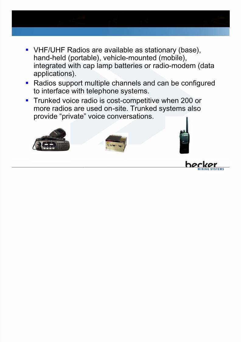
VHF/UHF Radios are available as stationary (base),hand-held (portable), vehicle-mounted (mobile),integrated with cap lamp batteries or radio-modem (dataapplications).
Radios support multiple channels and can be configuredto interface with telephone systems.
Trunked voice radio is cost-competitive when 200 ormore radios are used on-site. Trunked systems alsoprovide “private” voice conversations.

7/21/2019 Smart Com 150 Manual English V5_14
http://slidepdf.com/reader/full/smart-com-150-manual-english-v514 6/121
1.2 Simplex Radio System
• Transmit (TX) and Receive (RX)
frequencies are the same.
• UHF is a good choice for room &
pillar type mines.
• Line of sight communication (LOS):
VHF
150 MHz TX
150 MHz RX
UHF
455 MHz TX
455 MHz RX
VHF
150 MH
z TX
150 MHz RX
UHF
455 MHz TX
455 MHz RX

7/21/2019 Smart Com 150 Manual English V5_14
http://slidepdf.com/reader/full/smart-com-150-manual-english-v514 7/121
1.3 Half-Duplex Radio
Mountain
Radio #1150 MHz RX
170 MHz TX
Obstructions or extreme distances between the radios will
prevent simplex radio from working. To remedy this a
Repeater is added to create a half duplex communication
network.
PTT
Repeater
170 MHz RX150 MHz TX
Radio #2
150 MHz RX170 MHz TX

7/21/2019 Smart Com 150 Manual English V5_14
http://slidepdf.com/reader/full/smart-com-150-manual-english-v514 8/121
1.4 Leaky Feeder is…?
Leaky Feeder cable runs along tunnels and emits and
receives radio signals. The cable is leaky since it has
gaps or slots in its outer shielding to allow signal to leak
into or out of the cable along it's entire length.
Radio Transmit
170 MHz VHF
455 MHz UHF
Radio Receive
150 MHz VHF
475 MHz UHF

7/21/2019 Smart Com 150 Manual English V5_14
http://slidepdf.com/reader/full/smart-com-150-manual-english-v514 9/121
1.5 Real Time Communications
Leaky Feeder acts like a long antenna, connecting Radios
to Repeaters.

7/21/2019 Smart Com 150 Manual English V5_14
http://slidepdf.com/reader/full/smart-com-150-manual-english-v514 10/121
2.0 Leaky Feeder Concept
2.1 Leaky Feeder Highway
2.2 Leaky Feeder RF Spectrum
2.2.1 Smart Com 150 Band pass
2.2.2 Becker Smart Com 150 Band pass
2.2.3 Smart Com 450 Band pass2.3 Data - Smart Com + Ethernet
2.4 Data - Low Speed, Mine-Wide Data

7/21/2019 Smart Com 150 Manual English V5_14
http://slidepdf.com/reader/full/smart-com-150-manual-english-v514 11/121
2.1 Leaky Feeder Highway
Leaky Feeder is analogous to a
divided, multi-lane highway.
A single highway (cable) carriesseveral lanes of traffic
(channels) in opposite directions
(band-pass) with a median
(guard band) between them to
prevent collisions.

7/21/2019 Smart Com 150 Manual English V5_14
http://slidepdf.com/reader/full/smart-com-150-manual-english-v514 12/121
2.2 Leaky Feeder RF Spectrum
Guard Band
Downstream
• Downstream channels
are connected directly to
Repeater transmitter,thus all channels are at
same strong RF power.
• Downstream channels
drive Local Diagnostic
LED’s.
Upstream• Upstream signals are
at different RF power
depending (mainly)
on distance between
U/G radio and LF
cable
Base Station & Repeaters
Frequency

7/21/2019 Smart Com 150 Manual English V5_14
http://slidepdf.com/reader/full/smart-com-150-manual-english-v514 13/121
2.2.1 Smart Com 150 Band pass
Guard Band172-174
Downstream
(145-160 MHz)
Upstream
(170-185 MHz)
Base Station & Repeaters
Frequency
R F P
o w e r
150-156
16 Channels Voice
Radio. All
Downstream radio
signals are at same
RF power Ethernet
Downstream
(optional)
16 Channels
Voice/Data Radio
Upstream signals are
at different RF power
depending (mainly)
on distance from
cable.
Ethernet
Upstream or CCTV
NTSC 7/8
PAL 6/7
(optional)
RNG-AMP, RIS-AMP Band pass :

7/21/2019 Smart Com 150 Manual English V5_14
http://slidepdf.com/reader/full/smart-com-150-manual-english-v514 14/121
Smart Com 150 Band pass
170-185 MHz
145-160 MHz
Downstream Signals
Upstream Signals
RNG-AMP, RIS-AMP Band pass :

7/21/2019 Smart Com 150 Manual English V5_14
http://slidepdf.com/reader/full/smart-com-150-manual-english-v514 15/121
2.2.2 Becker Smart Com 150 Band pass
BSC-AMP Band pass:
G u a r d B a n d
Base Station & Repeaters
Frequency
Downstream
Voice145-160 MHz
Upstream
Voice170-185 MHz
R F
P o w e r
Upstream
CMTS
25-42 MHz
DownstreamCMTS
80-110 MHz
16 Channels Voice/Data
All Downstream radio
signals are at the same
RF power
16 Channels Voice/Data
Radio
Upstream signals are at
different RF power
depending (mainly) on
distance from cable.

7/21/2019 Smart Com 150 Manual English V5_14
http://slidepdf.com/reader/full/smart-com-150-manual-english-v514 16/121
Becker Smart Com 150 Band pass
170-185 MHz
145-160 MHz
Downstream Signals
Upstream Signals
BSC-AMP Band pass:

7/21/2019 Smart Com 150 Manual English V5_14
http://slidepdf.com/reader/full/smart-com-150-manual-english-v514 17/121
2.3 Data – Smart Com + Ethernet
Connect industry standard cable modems to
Smart Com to provide 54 Mbps Ethernet
hotspots.
Connect standard Ethernet equipment includingwireless networking equipment.
CMIIP Camera
PC
VOIP Handset
Cable
Modem
WLAN
SP2
Non-Intrinsically Safe
equipment

7/21/2019 Smart Com 150 Manual English V5_14
http://slidepdf.com/reader/full/smart-com-150-manual-english-v514 18/121
2.4 Data – Low Speed, Mine-Wide Data
1. Low-speed (9600 bps) wireless networks can run over Leaky Feeder.
2. “ Master” Radio Modem in Base Station is connected to main PC/PLC.
3. “ Slave” units are connected to PLCs or RTUs.

7/21/2019 Smart Com 150 Manual English V5_14
http://slidepdf.com/reader/full/smart-com-150-manual-english-v514 19/121
3.0 RF Power Measurement
3.1 “Relative” Measurements
3.2 Decibels: dB and dBm
3.3 Gain and Loss using dB’s
3.4 dB’s and Power

7/21/2019 Smart Com 150 Manual English V5_14
http://slidepdf.com/reader/full/smart-com-150-manual-english-v514 20/121
3.1 “ Relative” Measurements
• Temperature units are °C.
• Reference level is 0 °C.
• All temperatures are relative,
the numbers just indicate
higher/lower than reference
level of 0 °C.
+25C
0 C
-25C

7/21/2019 Smart Com 150 Manual English V5_14
http://slidepdf.com/reader/full/smart-com-150-manual-english-v514 21/121
3.2 Decibels: dB and dBm
dB’s are ratios of RF power levels that simplify
calculations of RF loss and gain.
Calculating power level differences in dB works
just like calculating temperature differences in°C.
dBm is a measurement of the absolute power,
not a power ratio. Power can be expressed as
Watts, dBm and volts, but dBm and dB’s worktogether to make things easy. No kidding.

7/21/2019 Smart Com 150 Manual English V5_14
http://slidepdf.com/reader/full/smart-com-150-manual-english-v514 22/121
3.3 Gain and Loss using dB’s
-4 dBm -0 dBm = -4 dB
100 meters of Smart Com
150/150IS Leaky Feedercable has 4 dB loss.
Input RF power 0 dBm Output RF power -4 dBm
What is RF loss through 100 m LF cable?
Input RF power -20 dBm
Output RF power +4 dBm
What is the gain of the LF amplifier?
Gain or loss is the difference between output and input indBm and the result is expressed in decibels (dB).
+4 dBm – (-20 dBm) = +24 dB
Leaky Feeder amplifier provides
24 dB gain.

7/21/2019 Smart Com 150 Manual English V5_14
http://slidepdf.com/reader/full/smart-com-150-manual-english-v514 23/121
3.4 dB’s and Power
Decibels are logarithmic. Increasing a signal by 3 dB
doubles the power, decreasing a signal by 3 dB cuts the
power in half. An increase of 10 dB is 10x the power.
-10 dB -6 dB -3 dBGain/
Loss+3 dB + 6 dB +10 dB
-10 dBm -6 dBm -3 dBm 0 dBm 3 dBm 6 dBm 10 dBm
1/10 1/4 1/2 Power 2x 4x 10x
7/21/2019 Smart Com 150 Manual English V5_14
http://slidepdf.com/reader/full/smart-com-150-manual-english-v514 24/121
4.0 System Layout
4.1 Base Station Location
4.2 LF Cable Layout
4.3 System Layout Example
4.4 Smart Com 150 Gains/Losses4.5 Smart Com 150IS Gains/Losses
4.6 Smart Com 450 Gains/Losses
4.7 Smart Com 150IS System Layout
4.8 Smart Com 150IS System Notes

7/21/2019 Smart Com 150 Manual English V5_14
http://slidepdf.com/reader/full/smart-com-150-manual-english-v514 25/121
4.1 Base Station Location
IS Systems:
Must be installed on surface (Safe Area).
Non-IS Systems:
Non-IS Systems can benefit from the Base Stationinstalled underground as all four Head End branches
may be used. This reduces the requirement for U/G
DC supplies and also provides a form of redundancy.
Another benefit of U/G Base Stations is that it
reduces the number of amplifiers in cascade and
thus the noise floor.

7/21/2019 Smart Com 150 Manual English V5_14
http://slidepdf.com/reader/full/smart-com-150-manual-english-v514 26/121
4.2 LF Cable Layout
LF cable must be installed wherever communications is
required.
Allow for 10% extra cable when laying system out to
accommodate for drip loops and cable slack. Each cable run must be terminated by either a
Termination Unit or Stope Antenna.
Stope Antennas increase coverage by up to 200-300%
to provide coverage into stopes and other areas where
cable damage is likely.

7/21/2019 Smart Com 150 Manual English V5_14
http://slidepdf.com/reader/full/smart-com-150-manual-english-v514 27/121
4.3 System Layout Example

7/21/2019 Smart Com 150 Manual English V5_14
http://slidepdf.com/reader/full/smart-com-150-manual-english-v514 28/121
4.4 Smart Com 150 Gains/Losses

7/21/2019 Smart Com 150 Manual English V5_14
http://slidepdf.com/reader/full/smart-com-150-manual-english-v514 29/121
5.0 Splitter Installation
5.1 Smart Com 150/150IS SP2 Splitters
5.2 Smart Com 150/150IS SP3 Splitters
5.3 Smart Com 450 SP2 Splitters
5.4 Smart Com 450 SP3 Splitters
7/21/2019 Smart Com 150 Manual English V5_14
http://slidepdf.com/reader/full/smart-com-150-manual-english-v514 30/121
5.1 Smart Com 150/150IS SP2 Split ters
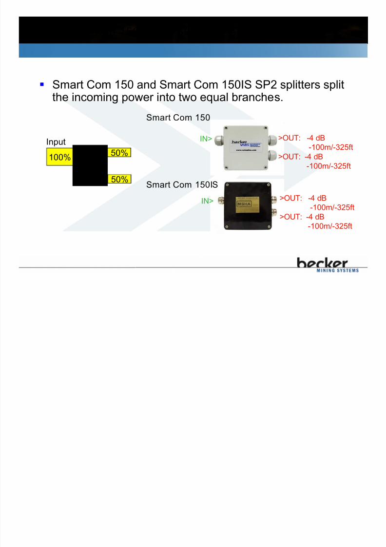
Smart Com 150 and Smart Com 150IS SP2 splitters splitthe incoming power into two equal branches.
100%50%
SP2
1
2
Input
Smart Com 150
IN> >OUT: -4 dB-100m/-325ft
>OUT: -4 dB
-100m/-325ft
Smart Com 150IS
IN>
>OUT: -4 dB
-100m/-325ft
>OUT: -4 dB
-100m/-325ft
50%

7/21/2019 Smart Com 150 Manual English V5_14
http://slidepdf.com/reader/full/smart-com-150-manual-english-v514 31/121
Smart Com 150/150IS SP2 Splitters
3m 400m
300m
-100m
-100m
Equivalent to 100m
300m
-100m
-100m
Equivalent to 100m of LF
+500m
7/21/2019 Smart Com 150 Manual English V5_14
http://slidepdf.com/reader/full/smart-com-150-manual-english-v514 32/121
5.2 Smart Com 150/150IS SP3 Split ters
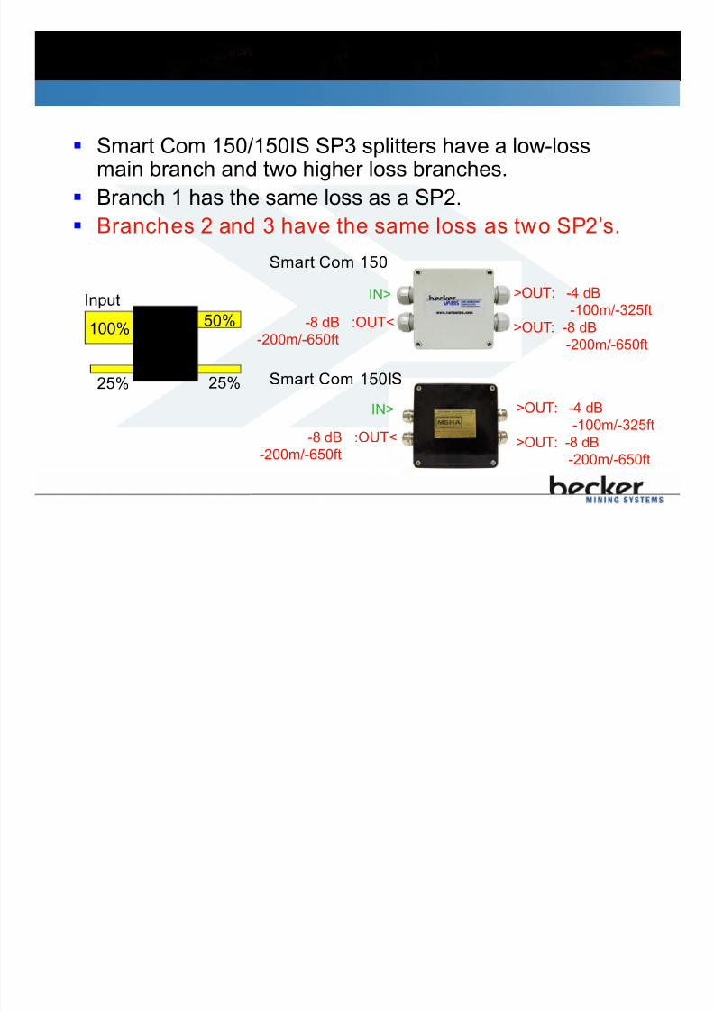
Smart Com 150/150IS SP3 splitters have a low-lossmain branch and two higher loss branches.
Branch 1 has the same loss as a SP2.
Branches 2 and 3 have the same loss as two SP2’s.
100%50%
SP3
25%
1
3 225%
Input
Smart Com 150
IN> >OUT: -4 dB
-100m/-325ft
>OUT: -8 dB
-200m/-650ft
-8 dB :OUT<
-200m/-650ft
Smart Com 150IS
IN> >OUT: -4 dB
-100m/-325ft
>OUT: -8 dB
-200m/-650ft
-8 dB :OUT<
-200m/-650ft

7/21/2019 Smart Com 150 Manual English V5_14
http://slidepdf.com/reader/full/smart-com-150-manual-english-v514 33/121
Smart Com 150/150IS SP3 Splitters
3m 400m
300m
300m
-100m
-200m-200m
Equivalent to 100m
2 0 0 m
Equivalent to 100m of LF
+500m

7/21/2019 Smart Com 150 Manual English V5_14
http://slidepdf.com/reader/full/smart-com-150-manual-english-v514 34/121
6.0 Amplifier Spacing
6.1 Amplifier Spacing
6.2 500m vs 350m Spacing
6.3 150/150IS Amplifier Spacing, Example 1
6.4 150/150IS Amplifier Spacing, Example 2
6.5 150/150IS Amplifier Spacing, Example 36.6 150/150IS Amplifier Spacing, Example 4
6.7 150/150IS Amplifier Spacing, Example 5
6.8 450 Amplifier Spacing, Example 1
6.9 450 Amplifier Spacing, Example 2
6.10 450 Amplifier Spacing, Example 36.11 450 Amplifier Spacing, Example 4
6.12 450 Amplifier Spacing, Example 5
6.13 Smart Com 150/150IS Amplifier Spacing Quiz

7/21/2019 Smart Com 150 Manual English V5_14
http://slidepdf.com/reader/full/smart-com-150-manual-english-v514 35/121
6.1 Amplifier Spacing
Line Amplifiers are installed to compensate for cable andsplitting losses.
Maximum
Amplifier
Gain (dB)
Amplifier
Spacing
Cable Loss at
highest
frequency
Reserve
Gain (dB)
Smart Com
150/150IS
(RNG-AMP,
RIS-AMP, BSC-
AMP)
28 500 m
1650 feet
23 dB/500 m 5
Smart Com 450
(450-AMP)
25 350 m
1150 feet
21 dB/350 m 4
RNG-AMP and RIS-AMP line amplifiers require first amplifier oneach Head End branch be spaced 350 m from Head End! BSC-
AMP amplifiers can be spaced 500m from head end.
7/21/2019 Smart Com 150 Manual English V5_14
http://slidepdf.com/reader/full/smart-com-150-manual-english-v514 36/121
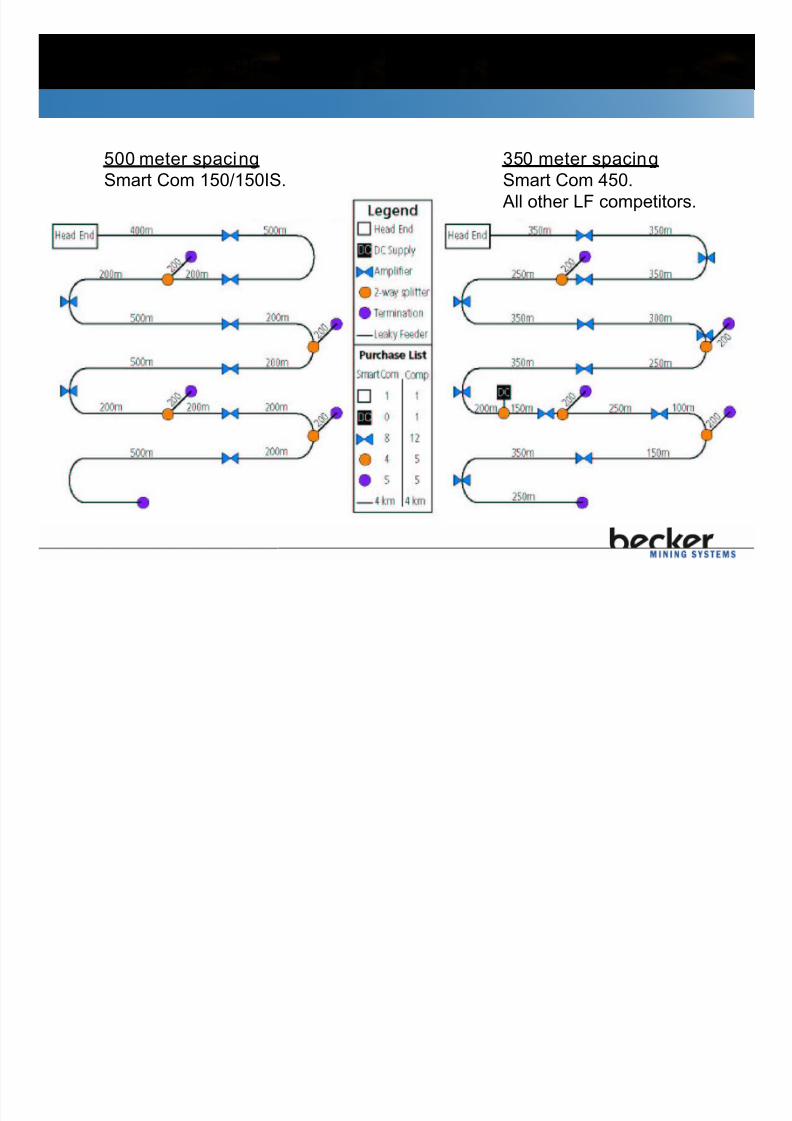
6.2 500m vs 350m Spacing
All other LF systems have 350 meter amplifier spacing.
500 meter spacing
Smart Com 150/150IS.
350 meter spacing
Smart Com 450.
All other LF competitors.

7/21/2019 Smart Com 150 Manual English V5_14
http://slidepdf.com/reader/full/smart-com-150-manual-english-v514 37/121
6.3 150/150IS Amplifier Spacing, Example 1
3m 400 meters
3m
+500 Meters
+500 Meters
3m 300 meters
300 meters
400 meters
300 meters
300 meters
BSC-AMP
RNG-AMP/RIS-AMP

7/21/2019 Smart Com 150 Manual English V5_14
http://slidepdf.com/reader/full/smart-com-150-manual-english-v514 38/121
6.4 150/150IS Amplifier Spacing, Example 2
3m 400 meters
+500 Meters
3m 300 meters
200 meters
200 meters
RNG-AMP/RIS-AMP
RNG-AMP/RIS-AMP/
BSC-AMP

7/21/2019 Smart Com 150 Manual English V5_14
http://slidepdf.com/reader/full/smart-com-150-manual-english-v514 39/121
6.5 150/150IS Amplifier Spacing, Example 3
100m 300 meters
+500 Meters
3m 200 meters
100 meters
100 meters
BSC-AMP
RNG-AMP/RIS-AMP/
BSC-AMP

7/21/2019 Smart Com 150 Manual English V5_14
http://slidepdf.com/reader/full/smart-com-150-manual-english-v514 40/121
6.6 150/150IS Amplifier Spacing, Example 4
3m 400 meters
+500 Meters
100m 200 meters
100 meters
100 meters
RNG-AMP/RIS-AMP
RNG-AMP/RIS-AMP/
BSC-AMP

7/21/2019 Smart Com 150 Manual English V5_14
http://slidepdf.com/reader/full/smart-com-150-manual-english-v514 41/121
6.7 150/150IS Amplifier Spacing, Example 5
100m 300 meters
+500 Meters
100m100 meters
3 meters
3 meters
RNG-AMP/RIS-AMP/
BSC-AMP
BSC-AMP

7/21/2019 Smart Com 150 Manual English V5_14
http://slidepdf.com/reader/full/smart-com-150-manual-english-v514 42/121
6.13 Smart Com 150/150IS Ampl if ier Spacing Quiz
5 0 0 m
___m
___m
3 0 0
m
1 0 0 m
(1)
Add amplifiers as necessary. Indicate spacing where
required.
2 0 0 m
2 0 0 m
1000m 600m
1
(2)
2 0 0 m
100m
200m

7/21/2019 Smart Com 150 Manual English V5_14
http://slidepdf.com/reader/full/smart-com-150-manual-english-v514 43/121
Smart Com 150/150IS Ampl if ier Spacing Quiz Answers
400
100 ___m
___m
3 0 0 m
1 0 0 m
(1)
200m
2 0 0 m
1000m600m1
(2)
2
0 0 m
100m
100m
100m500m 100m400m 500m
1 0 0 m
4 0 0 m
100m

7/21/2019 Smart Com 150 Manual English V5_14
http://slidepdf.com/reader/full/smart-com-150-manual-english-v514 44/121
7.0 Base Station Installation
7.1 What is a Base Station?
7.2 Typical Smart Com 150 Base Station Schematic7.3 Base Station Location
7.4 Smart Com 150 Base Station RF Flow
7.5 Leaky Feeder Head End
7.6 Smart Com 150 Head Ends
7.6.1 RNG-Hxx Head End
7.6.2 BSC-HE Head End
7.6.3 RNG-Hxx Head End Indications and Controls
7.6.4 BSC-HE Head End Indications and Controls7.6.5 RNG-Hxx RF Distribution
7.6.6 BSC-HE RF Distribution
7.6.7 RNG-Hxx Remote Diagnostic Connections
7.6.8 BSC-HE Remote Diagnostic Connections
7.6.9 Smart Com 150 Downstream – RNG-Hxx
7.6.10 Smart Com 150 Downstream – BSC-HE
7.6.11 Smart Com 150 Channel Plan
7.7 Smart Com 450 Head End7.7.1 Smart Com 450 Head End Indications
7.7.2 Smart Com 450 RF Distribution
7.7.3 Smart Com 450 Remote Diagnostics
7.7.4 Smart Com 450 Channel Plan
7.8 Base Station Power Supplies
7.9 Voice Repeaters
7.10 Telephone Interconnects
7/21/2019 Smart Com 150 Manual English V5_14
http://slidepdf.com/reader/full/smart-com-150-manual-english-v514 45/121
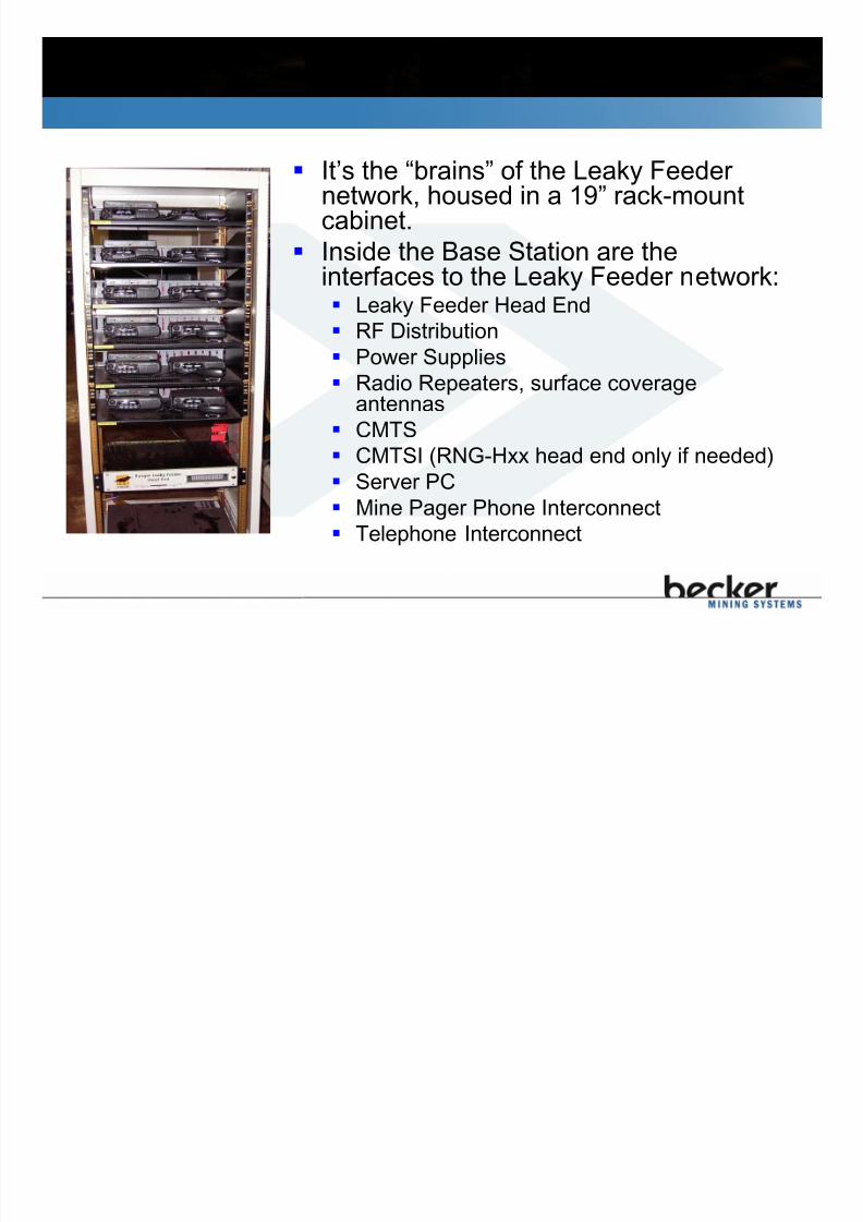
7.1 What is a Base Station?
It’s the “brains” of the Leaky Feedernetwork, housed in a 19” rack-mountcabinet.
Inside the Base Station are theinterfaces to the Leaky Feeder network:
Leaky Feeder Head End RF Distribution
Power Supplies
Radio Repeaters, surface coverageantennas
CMTS
CMTSI (RNG-Hxx head end only if needed) Server PC
Mine Pager Phone Interconnect
Telephone Interconnect

7/21/2019 Smart Com 150 Manual English V5_14
http://slidepdf.com/reader/full/smart-com-150-manual-english-v514 46/121
7.2 Typical Smart Com 150 Base Station Schematic
Tx3 Rx3
Rx2Tx2
Tx1 Rx1
Tx4 Rx4
12 Volt,90 Ah, Deep Cycle,Maintenance-Fr eeGel-Cell batteryBack View
+ _
L2 L1 B2 B1
Antenna
10Base-T
Tx0- 16 Rx0 -16
H/EIN
Leaky Feeder Connections
AC 120V
CablePass-Through
1 2 3 4
15A
RNG-RPT1, Repeater, Channel 1
RNG-RPT1, Repeater, Channel 2
RNG-RPT1, Repeater, Channel 3
RNG-RPT1, Repeater, Channel 4
RNG-RF16, RF Distribution
RNG-SAN, Surface Coverage Kit
RNG-H36, Leaky Feeder Head End
PS-110, 12V Power Supply
RNG-BAT, Battery Backup
Tx0-16 Rx0 -16
LowPassF ilter
ChassisGround
HighPassF ilter
12
34
56
78
910
1112
1314
1516
COM
7 5 5 0
12
34
56
78
910
1112
1314
1516
COM
S
1 2
7550
2
S
3 1 1 2
S
1 2
Rx0-1
Rx1
HPF
Rx0Tx0
Tx1
Tx0-1
LPF
CAT5 Ethernet Cabling, RJ45
DC 12V
Notes:
1. Cabinets are typically
supplied and configured by
Varis Distributors.
2. Run RF coaxial cables and
DC power cables on oppositesides of the cabinet.
3. Label all cables at both ends.
Use naming convention
shown here.
4. Surface Antenna package
RNG-SAN does not includeantenna mounting hardware.

7/21/2019 Smart Com 150 Manual English V5_14
http://slidepdf.com/reader/full/smart-com-150-manual-english-v514 47/121
7.3 Base Station Location
Base Stations for Intrinsically Safe systems needto be on surface (Safe Area).
Dry, heated area with reliable, clean AC power.
If located outdoors a climate controlled NEMA4/4X enclosure is required.
Base Station should be placed so that access toboth front and rear doors is possible.
LF cables can enter Base Station cabinetthrough top of cabinet or through access panelon bottom of cabinet. Cable glands required tomaintain NEMA rating of cabinet.

7/21/2019 Smart Com 150 Manual English V5_14
http://slidepdf.com/reader/full/smart-com-150-manual-english-v514 48/121
7.4 Smart Com 150 Base Station RF Flow
RNG-Hxx Head End:

7/21/2019 Smart Com 150 Manual English V5_14
http://slidepdf.com/reader/full/smart-com-150-manual-english-v514 49/121
7.5 Leaky Feeder Head End
The Head End is the interface between Base
Station equipment such as Repeaters and the
Leaky Feeder cables.
The Head End unit also injects DC power ontothe Leaky Feeder cable to power the LF Line
Amplifiers.

7/21/2019 Smart Com 150 Manual English V5_14
http://slidepdf.com/reader/full/smart-com-150-manual-english-v514 50/121
7.6 Smart Com 150 Head Ends
Existing Smart Com 150 systems are available in three types:
RNG-H12, RNG-H16, RNG-H36. The RNG-H12 outputs 12
VDC onto the Leaky Feeder cable, the RNG-H16 outputs 16
VDC and the RNG-H36 outputs 30-36 VDC.
A new version of VHF head end is now available that is
backwards compatible with existing systems while supporting
the more advanced features now available on the new
generation of Smart Com 150 line amplifiers (BSC-AMP).The BSC-HE12 outputs 12 VDC, the BSC-HE16 outputs 16
VDC and the BSC-HE36 outputs 30-36 VDC.
7/21/2019 Smart Com 150 Manual English V5_14
http://slidepdf.com/reader/full/smart-com-150-manual-english-v514 51/121
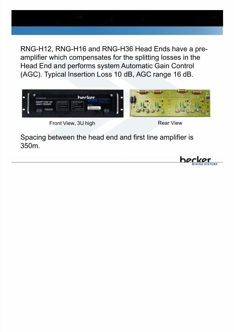
7.6.1 RNG-Hxx Head End
Front View, 3U high
RNG-H12, RNG-H16 and RNG-H36 Head Ends have a pre-
amplifier which compensates for the splitting losses in the
Head End and performs system Automatic Gain Control
(AGC). Typical Insertion Loss 10 dB, AGC range 16 dB.
Rear View
Spacing between the head end and first line amplifier is
350m.

7/21/2019 Smart Com 150 Manual English V5_14
http://slidepdf.com/reader/full/smart-com-150-manual-english-v514 52/121
7.6.2 BSC-HE Head End
Front View, 3U high
These Head Ends do no perform Automatic Gain Control
(AGC). Instead the insertion losses for the Voice
Upstream/Downstream and CMTS Upstream/Downstream
band passes are fixed. These head ends are backwards
compatible with older systems and components.
Rear View
BSC-HE head ends can support amplifier spacing of 500mbetween the head end and first line amplifier, unlike older
systems which were limited to 350m between the head end
and first line amplifier.

7/21/2019 Smart Com 150 Manual English V5_14
http://slidepdf.com/reader/full/smart-com-150-manual-english-v514 53/121
7.6.3 RNG-Hxx Head End Indications and Controls
LED’s for
each Branch
indicate that
DC voltage is
OK (Green) or
Branch isshorted (Red).
Jumpers areused to
enable/disable
each Branch.
The “RF Only”
jumper setting can
be used to connect
passive surface
antennas. This
setting may offer
increased lightningprotection in
addition to the
standard lightning
protection found
on RNG-SAN
Surface CoverageKits.
Output 16/36 VDC @ 2.5A, 0 dBm

7/21/2019 Smart Com 150 Manual English V5_14
http://slidepdf.com/reader/full/smart-com-150-manual-english-v514 54/121
7.6.4 BSC-HE Head End Indications and Controls
BSC-HE12, BSC-HE16,
BSC-HE36
Three settings are
available for eachbranch, RF+DC,
Terminate (no RF
or DC) and RF
Only.
LED’s for each Branch indicate thatDC voltage is OK (Green) or Branch
is shorted (Red).
Switches are used to
enable/disable each
Branch.
LED’s are provided
to show PWR,downstream
pilot/diagnostics
and upstream
diagnostics state.

7/21/2019 Smart Com 150 Manual English V5_14
http://slidepdf.com/reader/full/smart-com-150-manual-english-v514 55/121
7.6.5 RNG-Hxx RF Distribution
Included with all RNG-Hxx Head Ends.
16 channels for voice, data and video.
Connect all Repeater transmitters to TX ports and allRepeater receiver radios to the RX ports.
Transmit power into each port limited to +0 dBm.
TX RX

7/21/2019 Smart Com 150 Manual English V5_14
http://slidepdf.com/reader/full/smart-com-150-manual-english-v514 56/121
7.6.6 BSC-HE RF Distribution
RF distribution is now integrated into the head end enclosure
16 channels for voice, data and video.
Connect all Repeater transmitters to TX ports and all Repeaterreceiver radios to the RX ports.
Transmit power into each port is l imited to +30 dBm.
RF connections are also provided for CMTS Downstream/Upstreamchannels.

7/21/2019 Smart Com 150 Manual English V5_14
http://slidepdf.com/reader/full/smart-com-150-manual-english-v514 57/121
7.6.7 RNG-Hxx Remote Diagnostic Connections
•Connect Tx to RNG-RF16 TX0-16 port, Rx to RNG-RF16 RX0-
16 port using supplied 50 ohm
coaxial cables.
•Connect Power Leads to +12
VDC supply. Green “Power”LED and Red “Pilot” LED
should illuminate.
•Configure DRX IP and connect
to the mine’s network.
•Refer to Remote DiagnosticsInstallation Manual for complete
installation/calibration
procedure.
Power Leads
Tx
InputPower
Rx Port
Tx Port

7/21/2019 Smart Com 150 Manual English V5_14
http://slidepdf.com/reader/full/smart-com-150-manual-english-v514 58/121
7.6.8 BSC-HE Remote Diagnostic Connections
RNG-AMP, RIS-AMP Diagnostics:
• Connect Tx to DRX Tx port on the BSC-
HE board using a 1’ 50 ohm coaxial cable.
• Connect Rx to DRX Rx port on the BSC-
HE board using a 1’ 50 ohm coaxial cable.
• Connect Power Leads to +12 VDC supply.“Power” LED and “Pilot” LED should light.
• If installing the DRX in a system that has
350m spacing between the head end and
first amplifier, adjust the pilot to 0 dBm at
the output of the head end.
• If there is 500m spacing between the head
end and first amplifier, adjust the pilot to +4
dBm at the output of the head end.
Power Leads
Input
Power
Rx Port
Tx
Port
RNG-DRX
BSC-HE
Pilot
Level
Adjust
Inside BSC-HE Enclosure

7/21/2019 Smart Com 150 Manual English V5_14
http://slidepdf.com/reader/full/smart-com-150-manual-english-v514 59/121
BSC-HE Remote Diagnostic Connections
RNG-AMP, RIS-AMPDiagnostics:
•Configure the DRX IP and
connect to the inside Ethernet
port on the BSC-HE board as
shown.
•Next, connect the BSC-HE to
the mine’s network using the
Ethernet port on the outside of
the enclosure.
•Refer to Remote DiagnosticsInstallation Manual for
complete
installation/calibration
procedure.
RNG-DRX
BSC-HE
Inside BSC-HE Enclosure
Mines
Network

7/21/2019 Smart Com 150 Manual English V5_14
http://slidepdf.com/reader/full/smart-com-150-manual-english-v514 60/121
BSC-HE Remote Diagnostic Connections
BSC-AMP Diagnostics:
•Connect the Base-station server to the BSC-HE using a null-
modem cable as shown.
Connect to
Server

7/21/2019 Smart Com 150 Manual English V5_14
http://slidepdf.com/reader/full/smart-com-150-manual-english-v514 61/121
7.6.9 Smart Com 150 Downstream – RNG-Hxx
As the number of active repeaters changes, the AGC works
to keep the total Downstream RF power at +9 dBm. The
Upstream gain is controlled using the manual attenuation
switch (IC14) – leave gain control jumper at “AUTO”. The
upstream gain can be varied between 10 and 19 dB.
Voice 0 dBm
RNG-RF16 Insertion Loss 22 dB
Voice Repeater Transmitter
Head End Amplifier Gain:Downstream 10-25 dB
Upstream 10-19 dB
Voice -10 dBm, Pilot 0 dBm
Voice -22 dBm
Pilot -12 dBm Voice -1 dBm
Pilot +9 dBm
Head EndInsertion
Loss: 9 dB
DRX Downstream Pilot
Pilot +10 dBm
There is a 1.5 dB variation in RF levels at the four terminals on the Head End circuit
board. With the Downstream pilot active a Downstream signal in the range of -1 dBm
to +1 dBm indicates the system is operating normally.
AGC: AUTO

7/21/2019 Smart Com 150 Manual English V5_14
http://slidepdf.com/reader/full/smart-com-150-manual-english-v514 62/121
7.6.10 Smart Com 150 Downstream – BSC-HE
The new BSC-HE head ends have an integrated pilot that can run along
side the old DRX pilot. This means that the BSC-HE can provide
remote diagnostics for RNG-AMP, RIS-AMP and BSC-AMP line
amplifiers.
Voice +30 dBm
Insertion Loss 36 dB
Voice Repeater Transmitter
Voice: -6 dBm
DRX Pilot: 4 dBm
BSC-HE Pilot: -20 dBm
CMTS Down: +45 dBmV
DRX Pilot +10
dBm
Insertion Loss 6 dB
Insertion Loss 15 dB
CMTS Downstream +60 dBmVBSC-HE

7/21/2019 Smart Com 150 Manual English V5_14
http://slidepdf.com/reader/full/smart-com-150-manual-english-v514 63/121
7.6.11 Smart Com 150 Channel Plan
Compatible with
BSC-AMP,RNG-AMP and RIS-
AMP line amplifiers

7/21/2019 Smart Com 150 Manual English V5_14
http://slidepdf.com/reader/full/smart-com-150-manual-english-v514 64/121
Smart Com 150 Channel Plan
Smart Com 150 Channel List Version 4.0
RNG-AMP, RIS-AMP
BSC-AMP
BSC-AMP, RNG-AMP,
RIS-AMP
BSC-AMP, RNG-AMP,
RIS-AMP

7/21/2019 Smart Com 150 Manual English V5_14
http://slidepdf.com/reader/full/smart-com-150-manual-english-v514 65/121
7.8 Base Station Power Supplies
• 13.8 VDC, 40 Amp redundantsystem (2 x 20A supplies).
• Battery terminals to create
UPS. In-line fuse required
between battery and P/S
(supplied with RNG-BAT).
• Voltage & Current Meter.
• CSA certified.
• Not CE certified.
PS-110, PS-220
PS-UNIV-CE • CSA Certified.
• CE certified.
• Requires UPS.

7/21/2019 Smart Com 150 Manual English V5_14
http://slidepdf.com/reader/full/smart-com-150-manual-english-v514 66/121
7.9 Voice Repeaters
• One voice repeater is required for each voice channel.
• Typically supplied by Varis Distributor.
RNG-RPT1
(one channel)
RNG-RPT5(two channel)

7/21/2019 Smart Com 150 Manual English V5_14
http://slidepdf.com/reader/full/smart-com-150-manual-english-v514 67/121
7.10 Telephone Interconnects
INT-TEL-CE
INT-TEL
Telephone Interconnects connect a PABX telephone
line to a LF radio channel. Enables one non-private telephone connection per
connected channel.
Radios must be equipped with DTMF keypads to
access the Telephone Interconnect.• Typically
supplied by Varis
Distributor

7/21/2019 Smart Com 150 Manual English V5_14
http://slidepdf.com/reader/full/smart-com-150-manual-english-v514 68/121
8.0 LF Cable Installation
8.1 LF Cable Installation – Drift
8.2 LF Cable Installation – Shaft
8.3 IS Leaky Feeder Installation
8.4 VHF LF Cable & Tools
8.5 UHF LF Cable & Tools
8.6 RNG-500 LF Cable Preparation
8.7 RCF12-50 LF Cable Preparation
8.8 Smart Com 150 Component Connection
8.9 Smart Com 450 Component Connection

7/21/2019 Smart Com 150 Manual English V5_14
http://slidepdf.com/reader/full/smart-com-150-manual-english-v514 69/121
8.1 LF Cable Installation - Drift
X Avoid parallel branches as they
“ talk into” each other and
cause system problems!
When installing LF cable
horizontally secure every 2.5m/8ftto screening, rock bolts or other
support in tunnel.
Allow the LF cable to sag away
from supporting structure.
X Avoid tying cable tightly tometal beams or piping or
inside cable tray.
Tunnel/Drift
Best for Performance
(coverage range)
Best for Cable Protection
(recommended)

7/21/2019 Smart Com 150 Manual English V5_14
http://slidepdf.com/reader/full/smart-com-150-manual-english-v514 70/121
LF Cable Installation - Drift
3m
Leaky feeder components must
be located a minimum of 3 m
(10 ft) from each other.
Some slack leaky feeder is
recommended use a figure S
pattern, do not pinch or kink
the cable

7/21/2019 Smart Com 150 Manual English V5_14
http://slidepdf.com/reader/full/smart-com-150-manual-english-v514 71/121
LF Cable Installation - Drift
Any Parallel runs, must be
separated as much as possible
2.5 m/8 ft max between
attachments.
Let the cable droop at least
15 cm /6 inches from the
roof.

7/21/2019 Smart Com 150 Manual English V5_14
http://slidepdf.com/reader/full/smart-com-150-manual-english-v514 72/121
8.2 LF Cable Installation - Shaft
Secure with Ty-Raps every 3
m (10 ft) to brattice or 1/8”
SS messenger cable.
Loop cable 20 m (66 ft) ontoevery level. Install allcomponents on level, not inshaft.

7/21/2019 Smart Com 150 Manual English V5_14
http://slidepdf.com/reader/full/smart-com-150-manual-english-v514 73/121
8.4 VHF LF Cable & Tools
Smart Com 150 uses RNG-500 LF cable.
75 ohm impedance.
Solid copper center conductor, 16 solidcopper shield wires.
500 m (1640’) reels, 120 kg (265 lbs), 0.8m (32”) diameter x 0.5 m (20”) height.
RNG-500 installation requires:
Knife
Side/Cable cutters
¼” Flat Head screwdriver.

7/21/2019 Smart Com 150 Manual English V5_14
http://slidepdf.com/reader/full/smart-com-150-manual-english-v514 74/121
8.6 RNG-500 LF Cable Preparation
Care must be taken not to nick
or cut any of the conductors.
• Remove 6 cm (2.5 in) of theouter yellow & black sheaths.
• Form two stranded wires with 8of the outer strands in each.
• Remove white foam dielectric &
trim the center conductor to 2cm (0.75 in).

7/21/2019 Smart Com 150 Manual English V5_14
http://slidepdf.com/reader/full/smart-com-150-manual-english-v514 75/121
8.8 Smart Com 150 Component Connection
• Wrap outer stranded
conductors CW under the
outer terminals.
• Tighten outer terminals.
• Re-tighten center terminal.
• Hand-tighten the cable
grip nut.
• Amplifier and
Splitter connectors
marked
“HEADEND”must
be connected to
LF cable coming
from Head End.
• Loosen cable grip nut.
• Loosen terminal screws
(not captive).• Insert prepared cable
end and slide center
conductor under center
terminal.

7/21/2019 Smart Com 150 Manual English V5_14
http://slidepdf.com/reader/full/smart-com-150-manual-english-v514 76/121
9.0 Passive Component Installation
9.1 System Impedance
9.2 Two-way Splitter Installation
9.3 Three-way Splitter Installation
9.4 Termination Unit Installation
9.5 Stope Antenna Installation
9.6 Splice Unit Installation
9.7 Smart Com 150IS Barrier Unit Installation
9 1 S t I d
7/21/2019 Smart Com 150 Manual English V5_14
http://slidepdf.com/reader/full/smart-com-150-manual-english-v514 77/121
9.1 System Impedance
Smart Com 150/150IS system’s
characteristic impedance is 75 ohms.
Smart Com 450 system’s characteristic
impedance is 50 ohms.
This impedance difference means you
cannot mix Smart Com 150/150IS and
Smart Com 450 components or cable in asingle network!
9 2 T W S litt I t ll ti

7/21/2019 Smart Com 150 Manual English V5_14
http://slidepdf.com/reader/full/smart-com-150-manual-english-v514 78/121
9.2 Two-Way Splitter Installation
Smart Com 150/150IS Splitters have jumpers thatcan:
Terminate an unused/damaged branch.
Inject “RF Only” for runs of LF with noamplifiers so that short circuits in the LF cablewill not bring down the system.
RNG-SP2
UHF-SP2
1 2
H/E
Equivalent
LF cable
lengths
(loss) of
splitter
branches
Smart
Com
150/
150IS
Smart
Com
450
Branch 1, 2 100 m
(325’)
70 m
(230’)
1
2
H/E
RIS-SP2
H/E 1
2
9 3 Th W S litt I t ll ti

7/21/2019 Smart Com 150 Manual English V5_14
http://slidepdf.com/reader/full/smart-com-150-manual-english-v514 79/121
9.3 Three Way Splitter Installation
RNG-SP3
1
23
UHF-SP3
1
2
3
H/E
H/E
Equivalent LF cable lengths
(loss) of splitter branches
Smart Com
150/150IS
Smart Com
450
Branch 1 100 m (325’) 120 m (395’)
Branches 2 & 3 200 m (650’) 120 m (395’)
RIS-SP3
H/E
3
1
2
9 4 T i ti U it I t ll ti

7/21/2019 Smart Com 150 Manual English V5_14
http://slidepdf.com/reader/full/smart-com-150-manual-english-v514 80/121
9.4 Termination Unit Installation
Termination Units arerequired at the end ofeach LF cable to absorbRF signals, preventingreflections and “deadzones”.
RNG-TER
UHF-TERRIS-TER
9 5 St A t I t ll ti

7/21/2019 Smart Com 150 Manual English V5_14
http://slidepdf.com/reader/full/smart-com-150-manual-english-v514 81/121
9.5 Stope Antenna Installation
• Stope Antennas can be used in place of
Termination Units to increase off-cable
coverage up to 2-3 times.
• Install an amplifier and a length of LF
cable 3 m (10 ft) before the antenna forbest results (ensure previous amplifier is
at least 250 m (820 ft) away).
• Hang Stope Antenna on back with clear
view down drift.
RIS-AN1
RNG-AN1
9 6 S li U it I t ll ti
7/21/2019 Smart Com 150 Manual English V5_14
http://slidepdf.com/reader/full/smart-com-150-manual-english-v514 82/121
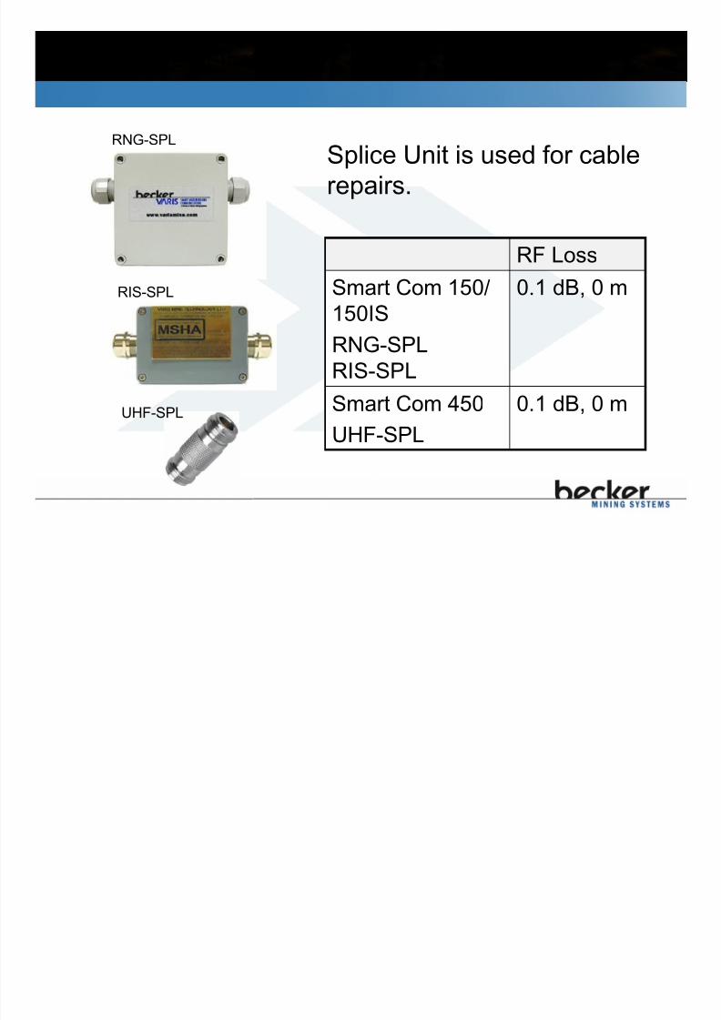
9.6 Splice Unit Installation
Splice Unit is used for cable
repairs.
RNG-SPL
RF LossSmart Com 150/
150IS
RNG-SPL
RIS-SPL
0.1 dB, 0 m
Smart Com 450
UHF-SPL
0.1 dB, 0 mUHF-SPL
RIS-SPL
10 0 Amplifier Installation

7/21/2019 Smart Com 150 Manual English V5_14
http://slidepdf.com/reader/full/smart-com-150-manual-english-v514 83/121
10.0 Amplifier Installation
10.1 Smart Com 150 Amplifier Installation10.2 Smart Com 150IS Amplifier Installation
10.3 Smart Com 450 Amplifier Installation
10.4 The 3 Meter Rule
10.5 Amplifier Gain Control10.6 Smart Com 150 Amplifier Local Diagnostics
10.7 Smart Com 450 Amplifier Local Diagnostics
10.8 Smart Com 150 Amplifier AGC
10.9 Smart Com 450 Amplifier AGC
10.10 Smart Com 150 Amplifier Manual Gain Control
10.11 Smart Com 450 Amplifier Manual Gain Control
10.12 Smart Com 150 Amplifier Remote Diagnostics
10.13 Smart Com 450 Amplifier Remote Diagnostics
10 1 Smart Com 150 Ampli fier Installation

7/21/2019 Smart Com 150 Manual English V5_14
http://slidepdf.com/reader/full/smart-com-150-manual-english-v514 84/121
10.1 Smart Com 150 Ampli fier Installation
RNG-AMP
“HEADEND”
terminals connectto the LF cablecoming from theBase Station.
BSC-AMP
Smart Com 150 Amplif ier Installation

7/21/2019 Smart Com 150 Manual English V5_14
http://slidepdf.com/reader/full/smart-com-150-manual-english-v514 85/121
Smart Com 150 Amplif ier Installation
Smart Com 150
amplifiers have jumperswhich isolate DCvoltage to help locateshort circuits.
RNG-AMP
BSC-AMP
Smart Com 150 Amplif ier Installation

7/21/2019 Smart Com 150 Manual English V5_14
http://slidepdf.com/reader/full/smart-com-150-manual-english-v514 86/121
Smart Com 150 Amplif ier Installation
RF Level
Jumper is to
select the
amplifiers mode,
Automatic or
Manual
Automatic is
recommended
Rotary switch adjusts Gain ifin manual mode
Button sends diagnostic
information to the head end
Unique ID that is used for
remote monitoring
BNC ports can be used
for sampling or testingthe amplif ier. A jumper
must be installed to
activate the port. The
jumper options are ‘RF
only’ or ‘DC and RF’
RNG-AMP
Smart Com 150 Amplif ier Installation

7/21/2019 Smart Com 150 Manual English V5_14
http://slidepdf.com/reader/full/smart-com-150-manual-english-v514 87/121
Smart Com 150 Amplif ier Installation
RF Level
Jumper is used to select the
amplifiers mode, Automatic or Manual Automati c is recommended
Rotary
switch
adjusts
Gain if in
manual
mode
Unique ID used for remote
monitoring
SMA ports can be used
for sampling or testing
the amplifier. A jumpermust be installed to
activate the port. The
jumper options are ‘RF
only’ or ‘DC and RF’
BSC-AMP
Used to calibrate in
Manual gain mode.
10 4 The 3 Meter Rule

7/21/2019 Smart Com 150 Manual English V5_14
http://slidepdf.com/reader/full/smart-com-150-manual-english-v514 88/121
10.4 The 3 Meter Rule
• Install amplifier before the splitter (closer to
Base Station).
• There must be a minimum 3 m (10 ft) of LF
cable between the amplifier and splitter.• Do not overlap cables or store Stope
Antennas bundled with amplifier.
Head End
10 5 Amplifier Gain Control

7/21/2019 Smart Com 150 Manual English V5_14
http://slidepdf.com/reader/full/smart-com-150-manual-english-v514 89/121
10.5 Amplifier Gain Control
Amplifiers compensate for the RF (Radio Frequency) cable
and splitting losses in the cable run preceding it in the
Downstream direction.
A m pl i f i e
r G ai n
RF High
RF OK
RF Low
10 6 Smart Com 150 Ampli fier Local Diagnostics

7/21/2019 Smart Com 150 Manual English V5_14
http://slidepdf.com/reader/full/smart-com-150-manual-english-v514 90/121
10.6 Smart Com 150 Ampli fier Local Diagnostics
• Any LED lit means DC voltage OK.
• Amber LED indicates radio signal is toohigh.
• Green LED indicates radio signal isOK. Green “OK” LED thresholds are
AGC or MGC-Calibrated: +3 to +5 dBm(-19 to -21 dBm for BSC-AMP), MGC
with Calibrate PB not pressed: +2 to +6dBm (-18 to -22 dBm for BSC-AMP).
• Red LED indicates radio signal is toolow.
If there is no Downstream radio channel active then the Red
(Low) LED will be on. To prevent this potentially confusing
behaviour, enable the Downstream Pilot signal on the RNG-
DRX.
10 8 Smart Com 150 Amplif ier AGC

7/21/2019 Smart Com 150 Manual English V5_14
http://slidepdf.com/reader/full/smart-com-150-manual-english-v514 91/121
10.8 Smart Com 150 Amplif ier AGC
• Key up radio to activate
repeater.
• Depress CALIBRATE p/b
for 2 seconds.
• Verify green LED is on.
• Amplifier continues to
monitor Downstreamsignals and adjust gain as
required to maintain “OK”.
Automatic gain control (AGC) is the recommended
setting. Set jumper to “AUTO”.
10 10 Smart Com 150 Amplifier Manual Gain Control
7/21/2019 Smart Com 150 Manual English V5_14
http://slidepdf.com/reader/full/smart-com-150-manual-english-v514 92/121
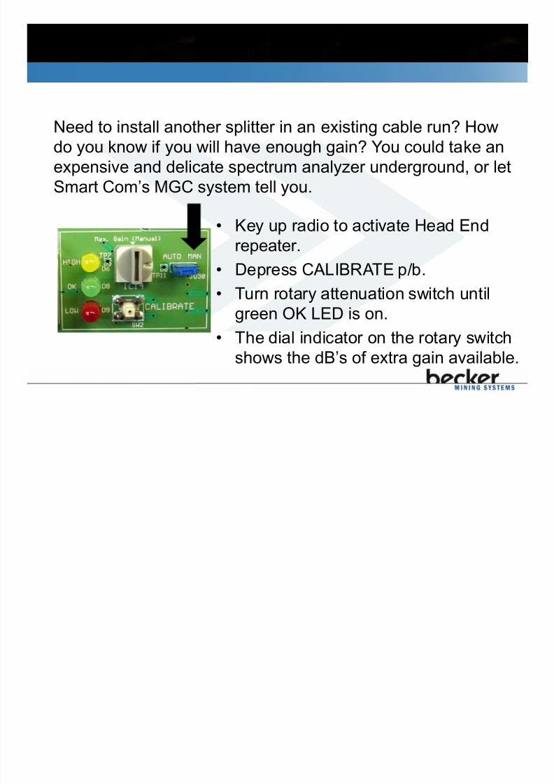
10.10 Smart Com 150 Amplifier Manual Gain Control
• Key up radio to activate Head End
repeater.
• Depress CALIBRATE p/b.
• Turn rotary attenuation switch untilgreen OK LED is on.
• The dial indicator on the rotary switch
shows the dB’s of extra gain available.
Need to install another splitter in an existing cable run? How
do you know if you will have enough gain? You could take an
expensive and delicate spectrum analyzer underground, or let
Smart Com’s MGC system tell you.
10 12 Smart Com 150 Amplifier Remote Diagnostics

7/21/2019 Smart Com 150 Manual English V5_14
http://slidepdf.com/reader/full/smart-com-150-manual-english-v514 93/121
10.12 Smart Com 150 Amplifier Remote Diagnostics
• Every 4-9 minutes
• When Calibrate
P/B is released
• Amplifier data canbe viewed from the
Remote
Diagnostics web
server.
The Remote Diagnostics
Transmit LED (D7)
illuminates when a Remote
Diagnostics packet is sent
RNG-AMP
Smart Com 150 Ampli fier Remote Diagnostics

7/21/2019 Smart Com 150 Manual English V5_14
http://slidepdf.com/reader/full/smart-com-150-manual-english-v514 94/121
Smart Com 150 Ampli fier Remote Diagnostics
• Amplifiers are polled
by the RD web
server at intervals
dependent on the #
of amps in thesystem.
• Amplifier data can
be viewed from the
Remote Diagnosticsweb server.
All three leds (D2, D3, D4)
light when a Remote
Diagnostics packet is sent
BSC-AMP
11 0 DC Supply Installation

7/21/2019 Smart Com 150 Manual English V5_14
http://slidepdf.com/reader/full/smart-com-150-manual-english-v514 95/121
11.0 DC Supply Installation
11.1 Smart Com 150 DC Supply
11.1.1 Smart Com 150 DC Supply Installation
11.1.2 Smart Com 150 DC Supply Upgrade
11.1.3 Smart Com 150 DC Supply Spacing
11.2 Smart Com 150IS DC Supply
11.2.1 150IS DC Supply Installation
11.2.2 150IS DC Supply Spacing
11.2.3 150IS DC Supply Layout
11.2.4 150IS DC Voltage Calculation
11.3 Smart Com 450 DC Supply
11.3.1 450 DC Supply Spacing
11.1 Smart Com 150 DC Supply

7/21/2019 Smart Com 150 Manual English V5_14
http://slidepdf.com/reader/full/smart-com-150-manual-english-v514 96/121
11.1 Smart Com 150 DC Supply
Two DC output voltages are available: RNG-DC16 provides 16 VDC and RNG-DC36 provides36 VDC.
A Power Coupler RNG-SC2 is supplied with each
DC Power Supply to tie it into the LF network. UseLF cable between coupler and DC Supply.
The RF loss for the coupler is < 1 dB andtherefore does not affect amplifier spacing.
Local Diagnostic LED’s
RNG-DC36, RNG-DC16 RNG-SC2
11.1.1 Smart Com 150 DC Supply Installation

7/21/2019 Smart Com 150 Manual English V5_14
http://slidepdf.com/reader/full/smart-com-150-manual-english-v514 97/121
11.1.1 Smart Com 150 DC Supply Installation
11.1.2 Smart Com 150 DC Supply Upgrade

7/21/2019 Smart Com 150 Manual English V5_14
http://slidepdf.com/reader/full/smart-com-150-manual-english-v514 98/121
11.1.2 Smart Com 150 DC Supply Upgrade
11.1.3 Smart Com 150 DC Supply Spacing

7/21/2019 Smart Com 150 Manual English V5_14
http://slidepdf.com/reader/full/smart-com-150-manual-english-v514 99/121
3 S a Co 50 C Supp y Spac g
12.0 Troubleshooting

7/21/2019 Smart Com 150 Manual English V5_14
http://slidepdf.com/reader/full/smart-com-150-manual-english-v514 100/121
g
12.1 Troubleshooting Strategy12.2 Smart Com 150 Quick Reference Guide
12.3 Becker Smart Com 150 Quick Reference Guide
12.4 Smart Com 150/150IS Remote Diagnostics
12.5 Smart Com 150/150IS Amplifier Local Diagnostics
12.6 Smart Com 450 Remote Diagnostics
12.7 Smart Com 450 Amplifier Local Diagnostics
12.8 Mine-Wide Failure
12.9 Area Failure
12.10 Short Circuit Repair
12.11 Base Station Testing
12.12 Upstream Band12.13 Noisy Upstream Band
12.14 Downstream Band
12.15 Noisy Downstream Band
12.1 Troubleshooting Strategy

7/21/2019 Smart Com 150 Manual English V5_14
http://slidepdf.com/reader/full/smart-com-150-manual-english-v514 101/121
g gy
Remote Diagnostics is key in detecting faults and seeing
what is going on in the system.
Comments from users are very useful in determining
what type of problem is occurring.
70% of all failures are due to cable and water damage.
Upstream noise and failed DC power supplies account for
the remaining 30% of problems.
Always start troubleshooting at the Head End. Start on
the branch with the reported fault, and work your waytowards the end of that branch.
Show DRX Help
12.2 Smart Com 150 Quick Reference Guide

7/21/2019 Smart Com 150 Manual English V5_14
http://slidepdf.com/reader/full/smart-com-150-manual-english-v514 102/121
Smart Com 150 Quick Reference Guide

7/21/2019 Smart Com 150 Manual English V5_14
http://slidepdf.com/reader/full/smart-com-150-manual-english-v514 103/121
12.3 Becker Smart Com 150 Quick Reference Guide

7/21/2019 Smart Com 150 Manual English V5_14
http://slidepdf.com/reader/full/smart-com-150-manual-english-v514 104/121
12.4 Smart Com 150/150IS Remote Diagnostics

7/21/2019 Smart Com 150 Manual English V5_14
http://slidepdf.com/reader/full/smart-com-150-manual-english-v514 105/121
g
Verif y BSC-HEserial
communications+1 to
+5 OKReserve
Gain
Should be less
than 15
minutes.
There
should be
no alarms.
Verify DRX-web
server
communication
RD Webserver compatible with RNG-Hxx and BSC-HE head ends
12.5 Smart Com 150/150IS Ampl if ier Local Diagnostics

7/21/2019 Smart Com 150 Manual English V5_14
http://slidepdf.com/reader/full/smart-com-150-manual-english-v514 106/121
RF LED
Indication
DC
Status/LED
RF Status Acti on
No LED’s Failed, below
minimumvoltage
Unknown Determine why DC voltage is low:
• Power Jumper setting (JU24, JU25 on RNG-AMP/RIS-AMP, JU1/JU2 on BSC-AMP)
• Fuse blown.
• No incoming voltage – check for cable short/open or DC Power Supply failure.
Red LED
(Previous Amplifier OK)
OK (any LEDlit indicatedDC voltage
OK)
Too Low Increased cable loss (addition of splitter, cable damage) requires more gain from amplifier.
Manual Gain Control (MGC)
• Decrease Attenuation Setting switch until Green OK LED On. For more accuracy, press and holdCalibrate button while adjusting the rotary attenuation switch.
Automatic Gain Control (AGC)
• Key up your radio and press and hold Calibrate button for 2 seconds. Verify OK LED On.
If adjusting gain does not achieve Green LED, then cable damage or new splitter prevents GreenLED On even with 0 (zero) attenuation.
• Find and repair cable damage.
• If new splitter installed, amplifier will show Red LED, but otherwise system performance will be
unchanged.
Green LED OK OK None
Amber LED
(Previous Amplifier OK)
OK (any LEDlit indicated
DC voltageOK)
Too High Manual Gain Control (MGC)
• Increase manual attenuation switch until Green OK LED on. For more accuracy, press and holdCalibrate button while adjusting attenuation switch.
Automatic Gain Control (AGC)
• Key up your radio and press and hold Calibrate button for 2 seconds. Verify OK LED On.
If problem persists:
• Ensure that amplifiers are not spaced too closely
• Ensure that an amplifier is not oscillating due to cable and stope antenna being bundled too
closely.
12.8 Mine-Wide Failure
7/21/2019 Smart Com 150 Manual English V5_14
http://slidepdf.com/reader/full/smart-com-150-manual-english-v514 107/121
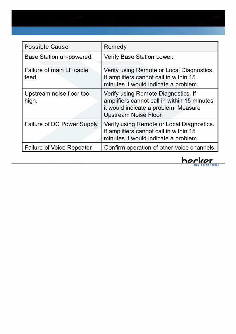
Possible Cause Remedy
Base Station un-powered. Verify Base Station power.
Failure of main LF cable
feed.
Verify using Remote or Local Diagnostics.
If amplifiers cannot call in within 15
minutes it would indicate a problem.
Upstream noise floor too
high.
Verify using Remote Diagnostics. If
amplifiers cannot call in within 15 minutes
it would indicate a problem. Measure
Upstream Noise Floor.
Failure of DC Power Supply. Verify using Remote or Local Diagnostics.
If amplifiers cannot call in within 15
minutes it would indicate a problem.
Failure of Voice Repeater. Confirm operation of other voice channels.
12.9 Area Failure

7/21/2019 Smart Com 150 Manual English V5_14
http://slidepdf.com/reader/full/smart-com-150-manual-english-v514 108/121
Possible Cause Remedy
Failure of LF cable feed. Verify using Remote or Local Diagnostics.
If amplifiers cannot call in within 15 minutes
it would indicate a problem.
Failure of DC Power
Supply.
Verify using Remote or Local Diagnostics.
If amplifiers cannot call in within 15 minutesit would indicate a problem.
Amplifier or cable fault. If amplifier cannot achieve Green LED then
either the amplifier is faulty or cable
between it and previous amplifier has too
high a loss. Verify amplifier spacing and
replace amplifier.
12.10 Short Circuit Repair

7/21/2019 Smart Com 150 Manual English V5_14
http://slidepdf.com/reader/full/smart-com-150-manual-english-v514 109/121
Short Circuits cause the DC voltage to drop while the DC current increases.
How to detect Short Circuits
Low voltage alarms on Remote Diagnostics.
Fault LED’s on DC Supplies.
Higher than normal current draw from DC Supplies. DC Supply output current “hiccupping”.
No LED’s on amplifiers (DC voltage below minimum voltage).
“Too Low” Red LED’s on amplifiers (RF level too low due to cable damage, cable open but not
shorted).
How to locate Short Circuits
Use information from Remote Diagnostics. Which sections of amplifiers are not calling in?
Start from DC Supply, and temporarily isolate cable sections using jumpers on splitters andamplifiers. Using a voltmeter, watch for increase in voltage (to normal) when branch isolated.
Once the faulty cable section has been identified, perform a visual check of the cable looking forobvious physical damage. If possible feel cable for damage.
How to repair Short Circuits Repair broken cable with splice units.
Replace damaged cable sections with new cable.
12.11 Base Station Testing

7/21/2019 Smart Com 150 Manual English V5_14
http://slidepdf.com/reader/full/smart-com-150-manual-english-v514 110/121
Smart Com 150/150ISConnect a Spectrum Analyzer to a spare Rx port on RNG-
RF16 or the BSC-HE. Monitor the Upstream band 170-185
MHz.
Spectrum Analyzer
Smart Com 450
Connect a Spectrum Analyzer to a spare Rx port on UHF-H00. Monitor the Upstream band 450-455 MHz.
12.12 Upstream Band

7/21/2019 Smart Com 150 Manual English V5_14
http://slidepdf.com/reader/full/smart-com-150-manual-english-v514 111/121
The Upstream band should look as shown below.
Upstream Band

7/21/2019 Smart Com 150 Manual English V5_14
http://slidepdf.com/reader/full/smart-com-150-manual-english-v514 112/121
It’s possible that you can hear
someone talking but not be able to
talk back. This indicates a problem
with the upstream communications.
12.13 Noisy Upstream Band

7/21/2019 Smart Com 150 Manual English V5_14
http://slidepdf.com/reader/full/smart-com-150-manual-english-v514 113/121
If noise is coming back to the Base Station from any or allof the LF branches it might look similar to below.
12.14 Downstream Band

7/21/2019 Smart Com 150 Manual English V5_14
http://slidepdf.com/reader/full/smart-com-150-manual-english-v514 114/121
It’s possible that someone can hear
you but you cannot talk back. This
indicates a problem with the
Downstream communications.
12.15 Noisy Downstream Band

7/21/2019 Smart Com 150 Manual English V5_14
http://slidepdf.com/reader/full/smart-com-150-manual-english-v514 115/121
Connect spectrum analyzer to the LF terminals at the Head
End.
13.0 Maintenance

7/21/2019 Smart Com 150 Manual English V5_14
http://slidepdf.com/reader/full/smart-com-150-manual-english-v514 116/121
13.1 Daily Maintenance
13.2 Monthly Maintenance
13.3 Annual Maintenance
13.1 Daily Maintenance

7/21/2019 Smart Com 150 Manual English V5_14
http://slidepdf.com/reader/full/smart-com-150-manual-english-v514 117/121
Use Remote Diagnostics (RD) each day.
Check for warnings and alarms.
The RD web server can be configured to send e-mail
when alarms are detected.
RD gives confidence in the system.
RD is easy to use, does not require a dedicated
computer and can support up to 50 simultaneous users.
13.2 Monthly Maintenance

7/21/2019 Smart Com 150 Manual English V5_14
http://slidepdf.com/reader/full/smart-com-150-manual-english-v514 118/121
1. Confirm Base Station operation:
1. Repeater transmitter levels
2. Clarity of voice communications
3. Noise in Upstream direction below -90 dBm
4. Head End circuit board Local Diagnostic LED’s OK
5. Verify backup batteries in place and on float charge
2. Test line components:
1. Amplifier and DC Supply Local Diagnostics LED’s OK
2. Verify backup batteries in place and on float charge
3. Verify minimum 30 meters communication range fromcable throughout mine.
13.3 Annual Maintenance

7/21/2019 Smart Com 150 Manual English V5_14
http://slidepdf.com/reader/full/smart-com-150-manual-english-v514 119/121
It is advised to perform a system audit on anannual basis. The audit verifies:
1. Remote Diagnostics configuration up to date withinstalled system.
2. Repeater sensitivity.3. Repeater transmit power and stability.
4. Head End splitter/combiner operation.
5. Downstream and Upstream noise floor.
6. Amplifier DC voltage and output levels.
7. Communication coverage and clarity, includingsurface.
Contact Information

7/21/2019 Smart Com 150 Manual English V5_14
http://slidepdf.com/reader/full/smart-com-150-manual-english-v514 120/121
Varis Mine Technology Ltd.
22 Brady Street, Unit 4
Sudbury, Canada P3E 6E1
Toll Free USA/Canada: 877-658-2747
Phone: 705-674-8111
Fax: 705-674-7834

7/21/2019 Smart Com 150 Manual English V5_14
http://slidepdf.com/reader/full/smart-com-150-manual-english-v514 121/121