smart antennas in radar systemsmonopulse function how to create high-quality Σ, ∆a, ∆e channels...
TRANSCRIPT

1 THALES-SR-TU-RF
©T
HA
LE
S N
ED
ER
LA
ND
B.V
. A
ND
/OR
IT
S S
UP
PL
IER
SS
ub
ject
to r
est
rict
ive
leg
end
on
titl
e p
age
Smart antennas in radar systems
14/11/2008 TU/EG van Werkhoven
22/4/2009 IEEE ComSoc NLR Amsterdam
G van Werkhoven

2 THALES-SR-TU-RF
©T
HA
LE
S N
ED
ER
LA
ND
B.V
. A
ND
/OR
IT
S S
UP
PL
IER
SS
ub
ject
to r
est
rict
ive
leg
end
on
titl
e p
age
Contents
Smart antennas in radar systems
� Short introduction
� Developments in Tracking and Multi-Function Radar
� Developments in Volume Search Radar
� Trends in technologies for future systems

3 THALES-SR-TU-RF
©T
HA
LE
S N
ED
ER
LA
ND
B.V
. A
ND
/OR
IT
S S
UP
PL
IER
SS
ub
ject
to r
est
rict
ive
leg
end
on
titl
e p
age
Contents
Thales in the Netherlands
� The main centre of excellencefor naval activities within Thales group
� 2.100 employees in 5 locations
� The largest defence companyin the Netherlands
� Sales Thales Nederland B.V. M€ ~450 in 2007
Surface Radar Fr-NL joint venture
Eindhoven
Land & Joint Systems
Enschede
Tx Cell
Delft
DECISAir Systems
Hengelo
Head OfficeNavalAir SystemsSecurity Solutions & Services
Huizen
Land & Joint Systems
Hengelo Site
4 THALES-SR-TU-RF
©T
HA
LE
S N
ED
ER
LA
ND
B.V
. A
ND
/OR
IT
S S
UP
PL
IER
SS
ub
ject
to r
est
rict
ive
leg
end
on
titl
e p
age
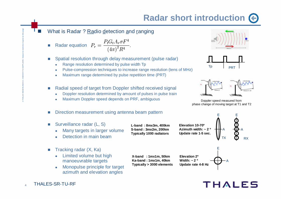
� What is Radar ? Radio detection and ranging
� Radar equation
� Spatial resolution through delay measurement (pulse radar)� Range resolution determined by pulse width Tp� Pulse-compression techniques to increase range resolution (tens of MHz)� Maximum range determined by pulse repetition time (PRT)
� Radial speed of target from Doppler shifted received signal� Doppler resolution determined by amount of pulses in pulse train� Maximum Doppler speed depends on PRF, ambiguous
� Direction measurement using antenna beam pattern
� Surveillance radar (L, S)� Many targets in larger volume� Detection in main beam
� Tracking radar (X, Ka)� Limited volume but high
manoeuvrable targets� Monopulse principle for target
azimuth and elevation angles
Radar short introduction
Elevation 10-70ºAzimuth width: ~ 2 ºUpdate rate 1-5 sec.
Elevation 2ºWidth: ~ 2 ºUpdate rate 4-8 Hz
Doppler speed measured from phase change of moving target at T1 and T2
L-band : 8mx3m, 400kmS-band : 3mx2m, 200kmTypically 1000 radiators
A
E
PRTTp
X-band : 1mx1m, 50kmKa-band : 1mx1m, 40kmTypically > 3000 elements
A
E
A
E
TX RX
5T
HA
LES
-SR
-TU
-RF
© THALES NEDERLAND B.V. AND/OR ITS SUPPLIERS Subject to restrictive legend on title page
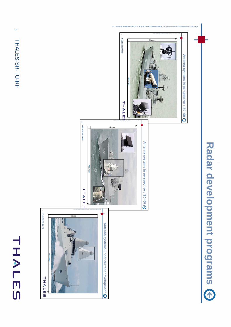
Radar developm
ent programs
1T
HA
LES
-SR
-TU
-RF
© THALE S NE DER LAND B.V. AN D/OR ITS S UPPLIER S Subject to restr ictive legend on title page
Antenna system
s in perspective : ’80-’90
Accu
racy
Range
31T
HA
LES
-SR
-TU
-RF
© THALES NED ERLAN D B.V . AND/OR ITS SUP PLIERS S ubject to restrictive legend on title page
Antenna system
s in perspective : ’90-’00
Accu
racy
Range
32T
HA
LES
-SR
-TU
-RF
© THALE S NE DER LAND B.V. AN D/OR ITS S UPPLIER S Subject to restr ictive legend on title page
Antenna system
s under current development
Accu
racy
Range

6 THALES-SR-TU-RF
©T
HA
LE
S N
ED
ER
LA
ND
B.V
. A
ND
/OR
IT
S S
UP
PL
IER
SS
ub
ject
to r
est
rict
ive
leg
end
on
titl
e p
age
Developments in Tracking and Multi-Function Radar ( X-band)
Design tools
Tec
hnol
ogy
Dual frequency reflector systems (X/Ka)� Ant : Reflector� BF : Pencil beam in azimuth and elevation� TX : TWT above deck � RX : monopulse receiver (3 channels)
APAR Multi-Function Radar (search/track/missile)• Ant : Waveguide array, >3000 elements• TX/RX : quad-pack TR modules
2 channels output per element• BF : 2D active electronic scanning array
Single RF beamformer on transmitRF monopulse (3 channel) on receive
Application in Seastar
Technology evolution for MFRBeamforming studies

7 THALES-SR-TU-RF
©T
HA
LE
S N
ED
ER
LA
ND
B.V
. A
ND
/OR
IT
S S
UP
PL
IER
SS
ub
ject
to r
est
rict
ive
leg
end
on
titl
e p
age
Array and integrated module development / X-band
8 TR element on PCB
RackSingle TR channel
GaAs MMICS
Validation
Stacked patch array
Patch array PCB proto
Re-usable components
� Stacked patch antenna PCB
� Multi-channel integrated TR module

8 THALES-SR-TU-RF
©T
HA
LE
S N
ED
ER
LA
ND
B.V
. A
ND
/OR
IT
S S
UP
PL
IER
SS
ub
ject
to r
est
rict
ive
leg
end
on
titl
e p
age
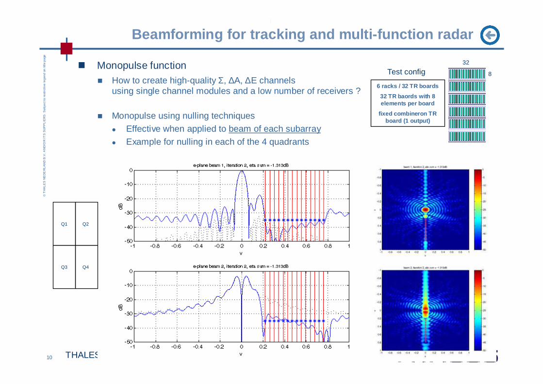
Beamforming for tracking and multi-function radar
� Monopulse function� How to create high-quality Σ, ∆A, ∆E channels
using single channel modules and a low number of receivers ?
� Monopulse using 4 quadrant receivers � Poor quality of elevation beam results� Combined weight optimization (Sum & Delta) fails
32
8
6 racks / 32 TR boards
32 TR baords with 8 elements per board
fixed combineron TR board (1 output)
Test config
Σ = Q1+Q2+Q3+Q4∆A = (Q1+Q3) – (Q2+Q4)∆E = (Q1+Q2)-(Q3+Q4)
Q1 Q2
Q3 Q4

9 THALES-SR-TU-RF
©T
HA
LE
S N
ED
ER
LA
ND
B.V
. A
ND
/OR
IT
S S
UP
PL
IER
SS
ub
ject
to r
est
rict
ive
leg
end
on
titl
e p
age
Beamforming for tracking and multi-function radar
� Monopulse function� How to create high-quality Σ, ∆A, ∆E channels
using >3000 single channel modules and a few receivers ?
� Mono-pulse using non-overlapping subarrays� TR board is subarray with weighting� 6 receivers to make Delta E beam
32
8
6 racks / 32 TR boards
32 TR baords with 8 elements per board
fixed combineron TR board (1 output)
Test config
R1
R2
R3
R4
R5
R6
10 THALES-SR-TU-RF
©T
HA
LE
S N
ED
ER
LA
ND
B.V
. A
ND
/OR
IT
S S
UP
PL
IER
SS
ub
ject
to r
est
rict
ive
leg
end
on
titl
e p
age
Beamforming for tracking and multi-function radar
� Monopulse function� How to create high-quality Σ, ∆A, ∆E channels
using single channel modules and a low number of receivers ?
� Monopulse using nulling techniques
� Effective when applied to beam of each subarray
� Example for nulling in each of the 4 quadrants
32
8
6 racks / 32 TR boards
32 TR baords with 8 elements per board
fixed combineron TR board (1 output)
Test config
Q1 Q2
Q3 Q4
11 THALES-SR-TU-RF
©T
HA
LE
S N
ED
ER
LA
ND
B.V
. A
ND
/OR
IT
S S
UP
PL
IER
SS
ub
ject
to r
est
rict
ive
leg
end
on
titl
e p
age
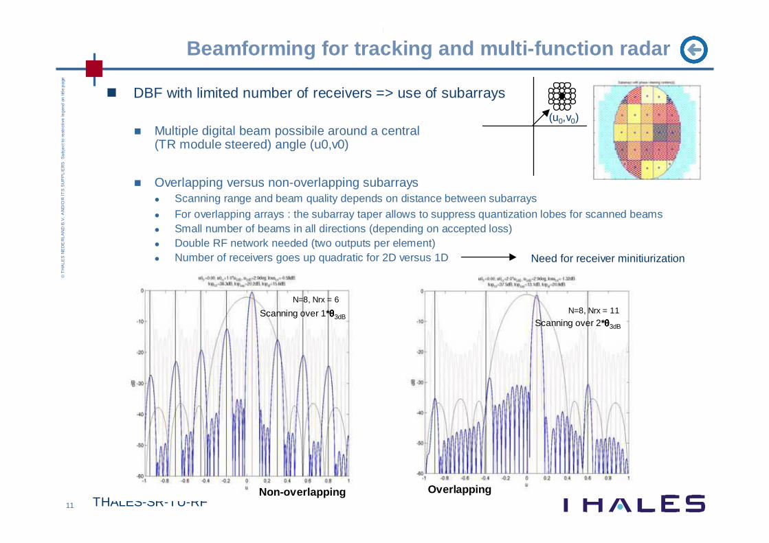
Beamforming for tracking and multi-function radar
� DBF with limited number of receivers => use of subarrays
� Multiple digital beam possibile around a central (TR module steered) angle (u0,v0)
� Overlapping versus non-overlapping subarrays� Scanning range and beam quality depends on distance between subarrays� For overlapping arrays : the subarray taper allows to suppress quantization lobes for scanned beams� Small number of beams in all directions (depending on accepted loss)� Double RF network needed (two outputs per element)� Number of receivers goes up quadratic for 2D versus 1D
(u0,v0)
N=8, Nrx = 11N=8, Nrx = 6
Non-overlapping Overlapping
Scanning over 1*θθθθ3dBScanning over 2*θθθθ3dB
Need for receiver minitiurization

12 THALES-SR-TU-RF
©T
HA
LE
S N
ED
ER
LA
ND
B.V
. A
ND
/OR
IT
S S
UP
PL
IER
SS
ub
ject
to r
est
rict
ive
leg
end
on
titl
e p
age
Developments in Volume Search Radar (L-band, S-band )
Time
Inte
grat
ion
leve
l
DA series surveillance radarPencil beam in azimuth with broadening in elevation Ant : Reflector system, mutliple feed possibleTX : TWT below deckRX : single receiver
Integrated Mast Module
• incl VSR + surface surveillance
Smart-L VSR (L-band long range 400km)• Ant : 1000 element 2D array with multiple RF line arrays• TX : single high power solid state transmitter below deck
high power ferrite phase shifters per line• RX : packaged multi-module receiver channels
Smart-S mkII VSR (S-band 200km) • Ant : 1000 element 2D array with multiple line arrays • TX : solid state transmitter with low power phaseshifter
per line, above rotating joint• RX : multi-channel receiver boards (MCR)
3D volume search
� 1D DBF in elevation (multiple beam in elevation)
� RF beamformer in azimuth
� TX mode with broadened and pencil beams
13 THALES-SR-TU-RF
©T
HA
LE
S N
ED
ER
LA
ND
B.V
. A
ND
/OR
IT
S S
UP
PL
IER
SS
ub
ject
to r
est
rict
ive
leg
end
on
titl
e p
age
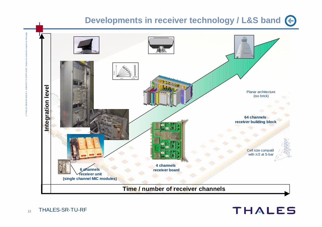
Developments in receiver technology / L&S band
Time / number of receiver channels
Inte
grat
ion
leve
l
4 channelsreceiver board
64 channelsreceiver building block
Cell size compatible with λ/2 at S-band
Planar architecture(iso brick)
6 channelsreceiver unit
(single channel MIC modules)
14 THALES-SR-TU-RF
©T
HA
LE
S N
ED
ER
LA
ND
B.V
. A
ND
/OR
IT
S S
UP
PL
IER
SS
ub
ject
to r
est
rict
ive
leg
end
on
titl
e p
age
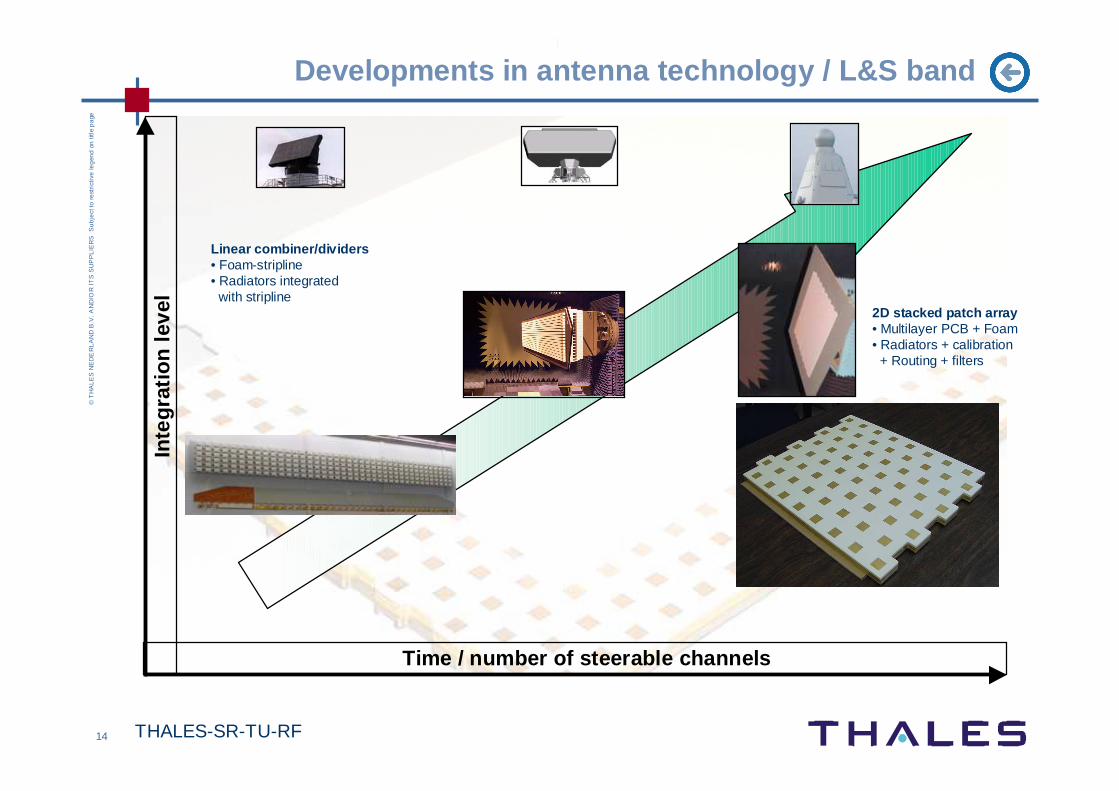
Developments in antenna technology / L&S band
Time / number of steerable channels
Inte
grat
ion
leve
l
Linear combiner/dividers• Foam-stripline • Radiators integrated
with stripline2D stacked patch array• Multilayer PCB + Foam • Radiators + calibration
+ Routing + filters

15 THALES-SR-TU-RF
©T
HA
LE
S N
ED
ER
LA
ND
B.V
. A
ND
/OR
IT
S S
UP
PL
IER
SS
ub
ject
to r
est
rict
ive
leg
end
on
titl
e p
age
Antennas in Integrated Mast Modules
Panoramic E/O systemGATEKEEPER
SHF Satcom
UHF Satcom
Non Rotating IFF
Integrated Communication Antennas System (ICAS)
Surface Surveillance radar SEASTAR
S-band Surveillance radar SMILE

16 THALES-SR-TU-RF
©T
HA
LE
S N
ED
ER
LA
ND
B.V
. A
ND
/OR
IT
S S
UP
PL
IER
SS
ub
ject
to r
est
rict
ive
leg
end
on
titl
e p
age
Seastar
SEASTARSea Environmental Assesment Surveillance Target Acquisition & Reconnaissance
RF testing in the Compact Antenna Test Range
Seastar prototype testing
Four face system• X-band Stacked patch array • Linear array for horizontal scan• Fixed elevation beam (with tilt compensation) in PCB• TR modules with RF network for single channel

17 THALES-SR-TU-RF
©T
HA
LE
S N
ED
ER
LA
ND
B.V
. A
ND
/OR
IT
S S
UP
PL
IER
SS
ub
ject
to r
est
rict
ive
leg
end
on
titl
e p
age
SMILE
Four S-band antenna faces • S-band stacked patch 2D array• TX aperture with high power modules (electronic scanning)• Planar receive array architecture• Receive aperture with receivers per element • Multiple digital rx beams (2D DBF)• Optical technologies for signal distribution
RX aperture
TX aperture
Multi-layer radome layer
SMILE 2D Multi-beam VSR in Littoral Environment
N_beams < N_rx• Video data throughput / cost• DBF already at panel level

18 THALES-SR-TU-RF
©T
HA
LE
S N
ED
ER
LA
ND
B.V
. A
ND
/OR
IT
S S
UP
PL
IER
SS
ub
ject
to r
est
rict
ive
leg
end
on
titl
e p
age
Trends for Future Mast Module
� Increase system capability & operational flexibility
� Volume & Surface search radar merged with MFR
� Integration of radar with other functions (comms, esm)
� Cost reduction through electronics integration
� Integrated modules to fit λ/2-grid of AESA� Radiator on packaging� Power generation / cooling� Receiver per element, integrated with ADC, fast data links
(1) Freeband, Ton Coonen, Cobra, TUE, 2008
(2) Antennas and packaging for millimeter-wave phased-array transceivers, J. Akkermans and D. Liu, EUMIC 2008
(3) Active Antennas for Electronically Scanned Arrays, B Jackson, University of Massachusetts
(2)
(3)
(1)
� Look also at developments in wireless community
19T
HA
LES
-SR
-TU
-RF
© THALES NEDERLAND B.V. AND/OR ITS SUPPLIERS Subject to restrictive legend on title page
Any questions ?

20 THALES-SR-TU-RF
©T
HA
LE
S N
ED
ER
LA
ND
B.V
. A
ND
/OR
IT
S S
UP
PL
IER
SS
ub
ject
to r
est
rict
ive
leg
end
on
titl
e p
age
Tracking antenna systems
Dual band tracking radar antenna (X+Ka bands)� Sum, Azimuth & Elevation beams� Parabolic reflector +
� X : Polarization twist reflectors
� Ka : Main reflector illumination
� Design issues � aperture illumination,
� spill-over losses,
� monopulse nulldepth
� radome
X-bandKa-band
∆A, ∆E signalΣ signal

21 THALES-SR-TU-RF
©T
HA
LE
S N
ED
ER
LA
ND
B.V
. A
ND
/OR
IT
S S
UP
PL
IER
SS
ub
ject
to r
est
rict
ive
leg
end
on
titl
e p
age
Tracking radar applications
Goalkeeper STIR 1.8mSTING
LIROD
Flycatcher MkII
22 THALES-SR-TU-RF
©T
HA
LE
S N
ED
ER
LA
ND
B.V
. A
ND
/OR
IT
S S
UP
PL
IER
SS
ub
ject
to r
est
rict
ive
leg
end
on
titl
e p
age
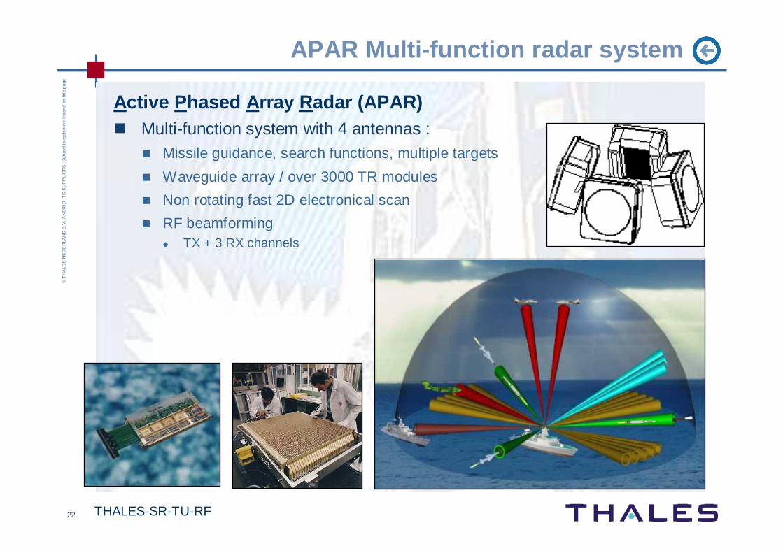
APAR Multi-function radar system
Active P hased A rray R adar (APAR)� Multi-function system with 4 antennas :
� Missile guidance, search functions, multiple targets
� Waveguide array / over 3000 TR modules
� Non rotating fast 2D electronical scan
� RF beamforming� TX + 3 RX channels

23 THALES-SR-TU-RF
©T
HA
LE
S N
ED
ER
LA
ND
B.V
. A
ND
/OR
IT
S S
UP
PL
IER
SS
ub
ject
to r
est
rict
ive
leg
end
on
titl
e p
age
APAR - Active Phased Array Radar
3.000 elements X-band Antenna
Verticcal RF-combiner
Backside Antenna
Column Assemblies
Horizontal RF combining
4 channel X-band T/R Module
+
TR-MODS COLUMN COMBINERSSum, Elevation / Tx
ROW COMBINERSTX, Elevation, Azimuth&Sum
3 RX channelsTX channel
(azimuth derived from sum)

24 THALES-SR-TU-RF
©T
HA
LE
S N
ED
ER
LA
ND
B.V
. A
ND
/OR
IT
S S
UP
PL
IER
SS
ub
ject
to r
est
rict
ive
leg
end
on
titl
e p
age
APAR dual channel TR module
circulator lnahpa dra phs/vga
antennaDELTA/TX
SUMCombiner networks
25 THALES-SR-TU-RF
©T
HA
LE
S N
ED
ER
LA
ND
B.V
. A
ND
/OR
IT
S S
UP
PL
IER
SS
ub
ject
to r
est
rict
ive
leg
end
on
titl
e p
age
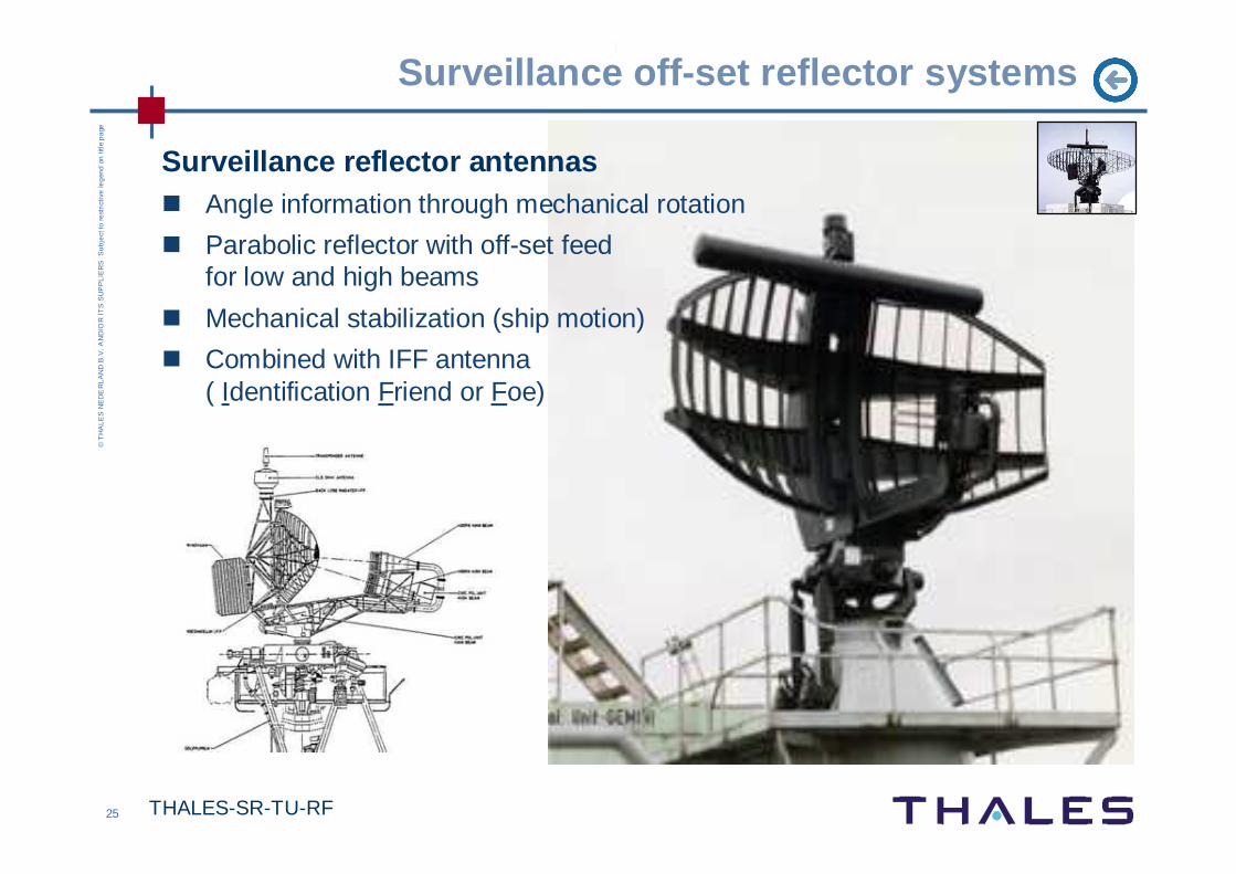
Surveillance off-set reflector systems
Surveillance reflector antennas� Angle information through mechanical rotation
� Parabolic reflector with off-set feed for low and high beams
� Mechanical stabilization (ship motion)
� Combined with IFF antenna ( Identification Friend or Foe)
26 THALES-SR-TU-RF
©T
HA
LE
S N
ED
ER
LA
ND
B.V
. A
ND
/OR
IT
S S
UP
PL
IER
SS
ub
ject
to r
est
rict
ive
leg
end
on
titl
e p
age
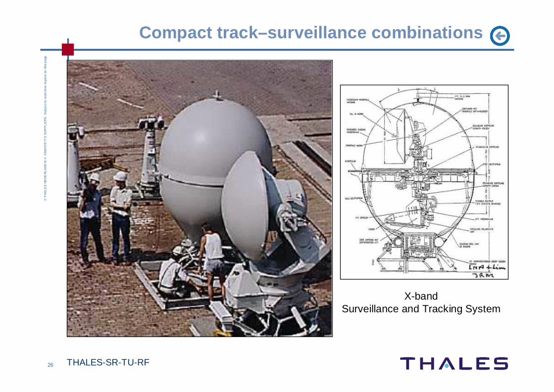
Compact track–surveillance combinations
X-band Surveillance and Tracking System

27 THALES-SR-TU-RF
©T
HA
LE
S N
ED
ER
LA
ND
B.V
. A
ND
/OR
IT
S S
UP
PL
IER
SS
ub
ject
to r
est
rict
ive
leg
end
on
titl
e p
age
Integrated Mast Module
> 1000300100301031
1
0.1
0.01
0.001
10
>100
RC
S (m
2 )
Speed (m/s)
> 1000300100301031 > 1000300100301031
Classification based on speed enhances reaction time and decision making
Rotor blades
Blue ocean
Littoral

28 THALES-SR-TU-RF
©T
HA
LE
S N
ED
ER
LA
ND
B.V
. A
ND
/OR
IT
S S
UP
PL
IER
SS
ub
ject
to r
est
rict
ive
leg
end
on
titl
e p
age
SEASTARSea Environmental Assesment Surveillance Target Acquisition & Reconnaissance
� Phased array combines high update rate with long time-on-target
� Detection of small surface targets (mines, periscopes, swimmers in sea clutter) not seen by navigation radars
� High range and Doppler resolution� Enhances the target/clutter ratio� Separates most targets from
sea clutter in Doppler domain
Seastar
There is a periscope somewhere…

29T
HA
LES
-SR
-TU
-RF
© THALES NEDERLAND B.V. AND/OR ITS SUPPLIERS Subject to restrictive legend on title page
Antenna system
s in perspective : ’80-’90
Accuracy
Range

30T
HA
LES
-SR
-TU
-RF
© THALES NEDERLAND B.V. AND/OR ITS SUPPLIERS Subject to restrictive legend on title page
Antenna system
s in perspective : ’90-’00
Accuracy
Range

31T
HA
LES
-SR
-TU
-RF
© THALES NEDERLAND B.V. AND/OR ITS SUPPLIERS Subject to restrictive legend on title page
Antenna system
s under current development
Accuracy
Range