sludge treatment project corrosion process chemistry follow-on
TRANSCRIPT

PNNL-16776
Test Plan: Sludge Treatment Project Corrosion Process Chemistry Follow-on Testing CH Delegard AJ Schmidt AP Poloski August 2007
Prepared for the U.S. Department of Energy under Contract DE-AC05-76RL01830
DISCLAIMER
This report was prepared as an account of work sponsored by an agency of the United States Government. Neither the United States Government nor any agency thereof, nor Battelle Memorial Institute, nor any of their employees, makes any warranty, express or implied, or assumes any legal liability or responsibility for the accuracy, completeness, or usefulness of any information, apparatus, product, or process disclosed, or represents that its use would not infringe privately owned rights. Reference herein to any specific commercial product, process, or service by trade name, trademark, manufacturer, or otherwise does not necessarily constitute or imply its endorsement, recommendation, or favoring by the United States Government or any agency thereof, or Battelle Memorial Institute. The views and opinions of authors expressed herein do not necessarily state or reflect those of the United States Government or any agency thereof.
PACIFIC NORTHWEST NATIONAL LABORATORY operated by BATTELLE
for the UNITED STATES DEPARTMENT OF ENERGY
under Contract DE-AC05-76RL01830
Printed in the United States of America
Available to DOE and DOE contractors from the Office of Scientific and Technical Information,
P.O. Box 62, Oak Ridge, TN 37831-0062; ph: (865) 576-8401 fax: (865) 576-5728
email: [email protected]
Available to the public from the National Technical Information Service, U.S. Department of Commerce, 5285 Port Royal Rd., Springfield, VA 22161
ph: (800) 553-6847 fax: (703) 605-6900
email: [email protected] online ordering: http://www.ntis.gov/ordering.htm
This document was printed on recycled paper. (9/2003)
PNNL-16776
Test Plan: Sludge Treatment Project Corrosion Process Chemistry Follow-on Testing Test Plan 53451-TP01, Rev. 0 August 2007 CH Delegard AJ Schmidt AP Poloski Prepared for the U.S. Department of Energy under Contract DE-AC05-76RL01830
Pacific Northwest National Laboratory Richland, WA 99352

PNNL-16776
ii
Forward
This test plan was prepared by the Pacific Northwest National Laboratory (PNNL) under contract with Fluor Hanford (FH). The test plan describes the scope and conditions to be used to perform laboratory-scale testing of the Sludge Treatment Project (STP) hydrothermal treatment of K Basin sludge. On July 3, 2007, the U. S. Department of Energy (DOE) provided direction(a) to FH regarding significant changes to the scope of the overall Sludge Treatment Project. As a result of the changes, FH directed PNNL to stop work on most of the planned activities covered in this test plan. Therefore, it is unlikely the testing described here will be performed. However, to preserve the test strategy and details developed to date, the test plan has been published. Prior to the changes in project direction, a final version of the test plan was issued for review. Consistent with the request of the DOE, Dr. J. Abrefah (PNNL) provided an independent technical review (Appendix C), and most of his comments have been incorporated into this document (Appendix E). FH also provided technical review (Appendix D) and these comments have been addressed (Appendix E). As a result of the project redirection, comments from other stakeholders (DOE, US Environmental Protection Agency, and BNG America) were not prepared.
(a) Department of Energy, RL, 07-KBC-0048, letter from MJ Weis (DOE-RL) to CM Murphy (FH), “Contract No.
DE-AC06-96RL13200 - CM Murphy (FH), “Path Forward Recommendations for Sludge Treatment Project,” dated July 3, 2007.
PNNL-16776
iii
Summary This test plan describes the scope and conditions to be used to perform laboratory-scale testing of the Sludge Treatment Project (STP) hydrothermal treatment of K Basin sludge. The proposed testing builds on the approach and laboratory test findings for both K Basin sludge and simulated sludge garnered during testing from September 2006 to March 2007 (Delegard et al. 2007). This plan aligns with the identified objectives developed for the K Basins STP in the related Data Quality Objectives (DQO) document (Makenas and Schmidt 2007) and incorporates the testing recommendations from the “Report on Expert Review of the Sludge Treatment Project Testing” (Abrefah et al. 2007). The testing campaign is considered a post-ROD (record of decision) treatability study under CERCLA (Comprehensive Environmental Release Compensation and Liability Act) and conducted using guidance contained in EPA Guidance for Treatability Studies under CERCLA (EPA 1992). Much of the testing in this plan will be conducted in a sequential manner that allows the knowledge obtained in one series to refine the next series of tests. Thus, the initial tests will be static tests designed to duplicate the previous experiments and to benchmark the behavior of sludge at the current lower design processing temperature for the STP. Testing with a broader set of sludge compositions will follow to improve the understanding of the chemistry producing high shear strength values. Testing will also be performed using a scaled (1-L) reactor to evaluate the effects of mixing, with the agitation level set to match that anticipated in the STP corrosion vessel. The planned testing is designed to yield further understanding of the nature of the chemical reactions, the effects of compositional and process variations and the effectiveness of various strategies to mitigate the observed high shear strength phenomenon observed by Delegard et al. (2007). These tests are being conducted to provide process validation and refinement vs. process development and design input. The expected outcome is to establish a level of understanding of the chemistry such that successful operating strategies and parameters can be implemented within the confines of the existing STP corrosion vessel design. K Basin Sludge Overview The sludge currently found in the water-filled Hanford K Basins is a mixture of particulate materials including irradiated metallic uranium reactor fuel, fuel corrosion products, wind borne soil, filter sand, corrosion products from racks (iron and aluminum), canisters (aluminum), and walls (concrete), spilled organic and inorganic Ion Exchange Module (IXM) media (mixed bed cation/anion resin and mordenite), and other minor constituents. By project definition, K Basin sludge is defined as any particulate material that can pass through a screen with 0.25-inch openings. The K Basins sludge is being managed as three distinct sludge streams: Container sludge, Settler Tank (Settler) sludge, and Knock-out Pot (KOP) sludge. The majority of the sludge, Container sludge (~41 m3), is being consolidated in the basins into large rectangular containers in the K West (KW) Basin, each which can hold up to 11.6 m3). Container sludge consists of sludge from the K East (KE) and KW Basin floors and pits along with smaller volumes of sludge from the KE fuel storage canisters and sludge from fuel washing. All primary KE and KW fuel (and fuel storage canisters) were washed in the Primary Cleaning Machine (PCM) located in the KW Basin. In addition to fuel washing, canister cleaning and scrap sorting operations occurred in the KW Basin. Sludge generated from these operations was

PNNL-16776
iv
vacuumed into the Integrated Water Treatment System (IWTS). During fuel washing, pieces of material larger than 0.25 inch (6350 µm) are removed in strainers (i.e., because of its particle size, strainer material is not considered sludge). Next, in the IWTS, larger sludge particles (~500 to 600 μm up to 6350 µm) are retained in Knock-out Pots (KOPs), which include internal or external filters. Total KOP sludge volume is ~0.26 m3. After passing through the KOPs, the IWTS sludge stream enters the Settler Tanks (ten parallel 20-inch diameter, 16-ft long tanks), where the finer particulate sludge (<500/600 µm) is allowed to settle. Total Settler sludge volume is ~5.4 m3. The accepted physical and chemical characteristics of the sludge are given in the design basis feed documents and in the sludge data book (Pearce 2001; Schmidt 2006; Plys and Schmidt 2006). Sludge sampling and laboratory analysis campaigns started in 1995 and have been performed to acquire specific characterization data for disposition of this sludge inventory. Results of these campaigns are documented (Pitner 1999; Makenas et al. 1996, 1997, 1998; Baker and Welsh 2001). STP Process for Sludge Disposition The three sludge types are to be sequentially treated within the STP process to create a grouted product acceptable for shipment and disposal to WIPP (the Waste Isolation Pilot Plant). Part of this process includes reaction of sludge, including its contained metallic uranium fuel particles, in liquid water at (nominally) 150°C(a) and 87 psig (5.9 atm). The objective of the processing is to convert metallic uranium completely into uranium oxides and thus preclude the formation of additional hydrogen during shipment to the WIPP through the corrosion reaction of uranium metal with water. As part of the nominal uranium metal corrosion process, as-settled sludge will be diluted with water (the extent of dilution is established for each of the three sludge types) and mechanically agitated. Design details and end points of the production-scale oxidation process have been provided by Woodworth (2006) and the operation temperature provided by the STP.(b) Results from Initial STP Process Tests Conducted to Evaluate Primary Chemical Behavior An independent review panel for the STP recommended small scale process chemistry tests be performed to validate the corrosion step (Heywood 2006). Subsequently, five tests (using actual sludge samples) were conducted in the first half of FY 2007 to examine the chemical and physical properties of sludge processed under the nominal STP process conditions (Delegard et al. 2007). Parameters evaluated included the effects of sludge composition, the presence of irradiated uranium metal fuel from the N
(a) The lower temperature (150°C) and pressure (87 psig) is new guidance from the Sludge Treatment Project. The
nominal operating temperature for the corrosion step formerly was 185°C with 225 psig operating pressure. The temperature decrease increases reaction time by a factor of ~4.4 according to the uranium metal anoxic aqueous corrosion rate law, log10 rate, μm/h = 9.694 – 3565/T (T in K) determined from review of the technical literature (Appendix G of Plys and Schmidt, 2006). With this rate equation, the reaction time to extinction of a ¼-inch (6350-μm) diameter uranium metal particle is 39 hours at 185°C and 171 hours at 150°C while the extinction time of a 600-μm maximum diameter uranium metal particle characteristic of Settler tube sludge is 16 hours at 150°C. The 185°C reaction times were based on the former reaction rate law (log10 rate, μm/h = 8.224 – 3016/T), which projects a 72-h extinction time for a ¼-inch diameter particle.
(b) Memorandum (draft) 07-STP-NJS-004, NJ Sullivan to DG Ruscitto, June 7, 2007, “Sludge Treatment Project Technical Services Recommendation Regarding DOE Direction to Reduce Corrosion System Temperature and Pressure,” Fluor Hanford, Richland, WA.

PNNL-16776
v
Reactor, the presence of flocculating agent, and the presence of organic ion exchange resin (OIER). The tests were each conducted with ~50-ml of settled sludge without agitation for ~7 to 72 hours at 185°C. The two sludge formulations tested represented nominal (vs. bounding) compositions of the two major sludge streams (Settler and Container) to be fed to the STP process. These tests were designed to specifically evaluate chemical and physical behavior aspects of the process but not engineering aspects. The tested sludges were representative of the high uranium concentration sludge arising from Settler Tubes (~5.4 m3) and the lower uranium concentration sludge collected in containers in the K Basins (Container sludge; ~41 m3). The STP process characteristics of the third type of sludge found in Knock-Out Pots (KOP sludge; ~0.26 m3) were not studied because of its limited volume (~0.26 m3), planned high dilution with water during processing, and favorable experience with processing uranium metal-rich sludge in prior hydrothermal testing at up to 95°C (Schmidt et al. 2003). Two of the five experiments were performed with high uranium content sludge (~70 wt% uranium, dry basis) representative of Settler tube sludge and contained irradiated uranium metal particles. The tests were conducted according to STP process conditions of 7 to 10 hours at 185°C. The uranium metal converted to UO2.x by corrosion in the water. The hydrothermal treatment decreased the settled sludge volume in both tests by about 20% to yield more free (supernatant) water, likely by dehydration of metaschoepite, a U(VI) mineral present in the sludge, to form dehydrated schoepite and reaction of metaschoepite with silica to form soddyite. Most importantly, the sludge products from the static tests had shear strengths of 120,000 to 170,000 Pa (assessed as “very stiff” according to soil physics descriptions). These strengths represented sharp increases from the shear strengths of similar untreated sludge which range from about 270 to 8100 Pa (described as “fluid mud” to “very soft”). The three remaining experiments used a composite of sludge samples representative of Container sludge and had lower (~16 wt%, dry basis) uranium. The sludge was reacted according to STP process conditions for ~72 hours at 185°C. The three test product solids were significantly softer, 9,000 to 16,000 Pa (i.e., “very soft” to “soft” according to soil physics descriptions), than those produced by the tests representing Settler sludge. Tests performed with and without added irradiated uranium metal fuel particles, flocculating agent, and OIER showed that none of these components had a significant impact on product sludge strength. Unlike the Settler sludge, the water content of the product Container sludge was not significantly affected by the processing. The mechanisms that resulted in the sharply higher strengths of the Settler sludge compared with the Container sludge are not known with certainty. However, high sludge strengths have been observed previously in the K Basins and in the laboratory. Sludge adhesion on vessel walls, noted in the recent tests with Teflon vessels, also has been observed in prior hydrothermal reaction tests, conducted from 60 to 95°C in stainless steel vessels, of floor sludge containing irradiated uranium metal fuel particles. Considerations for Follow-on STP Process Testing Considerations into further testing to address chemistry and engineering/design questions and thus support the STP processing are the focus of this Test Plan and were advanced in the prior report (Section 4.0 of Delegard et al. 2007). The problems were considered further under a DQO framework to help define potential avenues of experimental study, identify test limitations, and understand the decisions arising from application of the test findings (Makenas et al. 2007a). In parallel with the DQO process, an independent expert panel review of the prior testing (Delegard et al. 2007) and the proposed follow-on
PNNL-16776
vi
testing was conducted on April 26, 2007 (Abrefah et al. 2007). The expert panel provided some specific recommendations for the follow-on testing (described below). The physical and chemical STP process development questions arising from the prior report and refined by the DQO process are posed in the following problem statements.
1. The sludge treatment process must be able to recover from off-normal conditions such as the loss of agitation during or after the processing. The formation of a high shear strength product may affect the ability to recover from a loss-of-agitation incident.
2. The formation of a high shear strength product occurs at specific but unknown compositions and temperatures. The chemical reactions and the product phases which form during normal and off-normal processing are not well known and there is limited understanding of the mechanisms by which these phases affect sludge product properties, particularly strength.
3. The sludge treatment process might produce a high shear strength product that has unacceptable handling characteristics even under normal agitated operating conditions.
4. Sludge has been observed in previous tests to cling to Teflon test reaction vessel walls. Materials adhering to the stainless steel process vessel walls may degrade process performance such as wall heat transfer or adversely affect vessel emptying operations.
5. Although the temperature variations in the process are expected to be small, process interruptions can cause temperature cycling. The process vessel also will carry over a heel between batches. The effects of multiple thermal cycling of sludge are not known.
6. Gas retention in the product sludge varies significantly as shown by the initial non-agitated laboratory process tests. It is not known whether this will occur under agitated conditions and whether it will affect subsequent sludge handling and processing.
7. The sludge state during processing could affect the functioning of the demister in the processing containers through particulate transport by aerosol and foam formation.
Means to investigate and answer the physical and chemical questions are examined in this Test Plan while the engineering and design questions are evaluated to a limited extent, within the confines of the existing STP equipment designs. The laboratory testing approach is similar to the approach used in the prior tests (Delegard et al. 2007). Thus, much of the testing will occur under static (unstirred) hydrothermal process conditions using sludge samples from the K Basins and using simulated sludge. The effects of a broader range of test variables (sludge agitation, sludge composition and dilution, process temperature, test apparatus design) will also be investigated with the goals of addressing the problem issues identified by the DQO process and to give added assurance that the laboratory testing results will be applicable to the variety of process and material conditions encountered in the full-scale operations. Recommendations on the follow-on testing taken from the Expert Review Panel report (Abrefah et al. 2007) are:
“In summary the test plan outstanding trials should include: • Static trials on container sludge with typical uranium concentrations and enhanced Si, Al, Fe
concentrations to determine the level of aggregation compared to other Container sludge samples.

PNNL-16776
vii
• Static trials with uranium oxides (generated from depleted uranium metal) to simulate and better understand the behavior of high concentration uranium content sludges.
• Static trials to investigate the blending of high U samples with inert materials and solid loading.
• Static hot test to confirm dilution/blending strategies. • Larger scale stirring tests (with uranium surrogate material) as programmed in the current
process design trials. • Hot stirred trials in a Parr reactor for high U material (KOP and Settler Sludge).
These tests should be performed at different temperatures if dictated for nuclear safety reasons.”
The test plan currently includes test series that address these recommendations, with the exception of the last bullet: “hot trials with KOP and Settler sludge.” The stirred Parr reactor being procured for the “warm” trials is being designed with features that will facilitate its installation into the shielded facilities. However, at this time, the decision to install and test the stirred Parr reactor with actual sludge samples is being deferred and will be made based on the results of initial tests and STP direction. Favorable outcomes from static testing of actual sludge may obviate the need for the much more complex stirred tests with actual sludge provided sludge re-suspension can be established after a loss-of-stirring incident. Overview of Planned Testing An overview of the general sequence and decision logic of the planned testing is outlined in Figure S.1. Table S.1 provides a summary test matrix, including objectives, sludge composition (simulant and actual sludge), test configuration (e.g., static or agitated), and test conditions (temperature and time). Although the initial testing is defined in considerable detail within this Test Plan, the conditions for the latter tests are generalized and will be refined (including any needed duplicate tests) for each series within specific test instructions based on the results of the preceding tests. Initial and product sludge qualities to be investigated in these test series include shear strength, settled sludge and particle density, water content and pH, and chemical phase and morphological changes as determined by X-ray diffractometry (XRD) and scanning electron microscopy (SEM), respectively. The adherence of the sludge products onto the stainless steel test vessel walls and evidence of foaming also will be observed for each test. As shown in Figure S.1, the testing will be performed using K Basin sludge samples (referred to as “hot” tests), simulated sludge materials generated from non-irradiated uranium (“warm” tests), and non-radioactive simulants without uranium addition (“cold tests”).(a) K Basin sludge samples collected during sampling and analysis campaigns in 1995 to 2003 will be used for the “hot” testing. These sample quantities are limited and must be used judiciously because of the complexity of obtaining additional representative samples. A prerequisite activity to this Test Plan is the gathering, compositing, and summarizing of analytical data for the K Basin sludge materials to be used in this testing. Sampling of sludge from the engineered container (SCS-CON 220) being used to collect sludge from the floor and pits of the KW Basin is planned for the first quarter of FY 2008. The KW Container sampling is specifically (a) The terms “hot”, “warm”, and “cold” refer to radiation nomenclature; hot tests using typical radioactive K Basin
sludge; warm tests using a simulant of non-irradiated uranium metal that is then oxidized to form compounds similar to those found typical K Basin sludge; and cold tests, which contain no radioactive or uranium constituents.

PNNL-16776
viii
focused on analysis for nuclear material safeguards purposes. However, sufficient sample material is anticipated to allow use in Test Series 2.3 (Figure S.1). Simulated sludges containing un-irradiated depleted uranium will be used in the “warm” tests. These test series are called “warm” because the non-irradiated uranium materials used in these tests are mildly (naturally) radioactive compared with the K Basins sludge, but must still be handled in an appropriate radiological laboratory. The “warm” tests will use both uranium and non-uranium compounds. The uranium compounds used for the “warm” test simulated sludge will include uranium metal, uraninite [nominally UO2.x, a U(IV) phase], and metaschoepite [UO3·2H2O, a U(VI) phase]. These are the three primary uranium phases observed in the K Basin sludge. The preparation and characterization of the uraninite and the metaschoepite simulants constitute Test Series 3.1. The uraninite will be created under contract by a private vendor by corroding non-irradiated uranium metal turnings under anoxic water conditions. Metaschoepite will be synthesized in the PNNL laboratories by aerobic oxidation of uraninite. Methods to produce these uranium materials are described in this Test Plan.

PNNL-16776
ix
Cold tests
Hot (actual) sludge tests
Warm (depleted uranium) tests
Uranium Compound Simulant Validation (3.1)Establish and validate production of uraninite and metaschoepite compounds generated in lab from depleted uranium for use in follow-on WARM tests.
Al, Fe, & Si Component Evaluation (2.1)Evaluate key non-fuel origin sludge components (Al, Fe, and Si) concentrations and mineral forms.
pH Adjustment and Control (3.3)Evaluate "bounding" uranium mixture properties (as det'd, in 3.2) at varying pH [e.g., CaCO3, Ca(OH)2, phosphate].
Benchmark at New Operating Temperature (1.1)Replicate original tests at lower (150°C) temperature with genuine sludge samples to mimic Settler and Containerized sludge. Evaluate several uranium concentrations. Effects of flocculent and organic ion exchange resin beads will not be tested.
Mixing System Setup (4.1)Establish mixed reactor system and test / demonstrate operational performance with non-radioactive simulant.
Uranium Compound Simulant Dilution Tests (3.3)Evaluate product properties with inert dilution of "bounding" uranium mixture (as determined in 3.2).
Uranium Compound Simulant Testing (3.2) Evaluate effects of varying uraninite and metaschoepite on product properties for high uranium content. Identify bounding composition for subsequent testing. Optionally, identify temperature effects.
Al, Fe, & Si in Container Sludge (2.2)Evaluate effects of high Al, Fe, and Si content with genuine KE Floor and Pit sludge samples.
Mixed Reactor Test (4.2)Evaluate "bounding" uranium mixture determined in 3.2 in mixing reactor.
Confirmation in Mixed Reactor (4.3)Evaluate optimized case uranium mixture (as determined in 3.3) in mixed reactor.
Are synthetic U oxides adequate
based on XRD and SEM?
Acceptable rheology?
Do approaches in 3.3 yield products with acceptable
properties?
Consider alternative test schemes
Further Al, Fe, and Si chemistry understanding required.
No
No
No Yes
Yes
Yes
Confirmation Static Test (3.4)Evaluate optimized case uranium mixture (as determined in 3.3) in static reactor with genuine sludge.
Static Tests with SCS CON 220 Sludge (2.3)Perform hot tests with KW Container 220 samples (should exhibit highest U concentration of all Container Sludge).
Confirmation in Mixed Reactor (4.4 - optional)Evaluate genuine sludge using optimized case treatment (as determined in 3.3) in mixed reactor.
Figure S.1. Test Matrix and Logic Outline

PNNL-16776
x
Table S.1 Test Matrix Summary Composition, wt% as Element, Dry Basis (b) Test ID Description/Objective Sludge Material
(a) U(IV) U(VI) U(0) Al Fe Si Temp (°C) / Time (hr)
1.1 Benchmark Hot Static Tests at New Operating Temperature (Mimic Container and Settler Sludge plus two intermediate U concentrations) 1 Mimic Container Sludge KC-4 16.6, total U 6.8 24.3 4.9 150/171 2 Intermediate U concentration KC-4 & KC-2/3 30.7, total U 6.1 16.8 3.5 150/171 3 Intermediate U concentration KC-4 & KC-2/3 44.9, total U 5.7 9.3 2.2 150/171 4 Mimic Settler Sludge KC-2/3 59.0, total U 5.2 1.8 0.8 150/16
2.1 Al, Fe, and Si Components, Cold Static Tests (Effects of aluminum and iron oxyhydroxides and blow sand on product rheology)
TBD Series (~10) cold tests to evaluate effects of aluminum and iron oxyhydroxides (bayerite, ferrihydrite) and blow sand on product rheology.
Non-rad simulants 0 0 0 3 - 16 8 - 42 0 - 36 150/171
2.2 Hot Static Tests for Evaluation of Non-U Components (Effects of high Al and Fe oxyhydroxides and silica concentrations on product rheology) 1 High aluminum KE Floor Sludge KC Floor Comp 11.9, total U 15.8 23.2 6.6 150/171 2 High iron KE Weasel Pit Sludge FE-5 4.1, total U 2.7 30.6 0.3 150/171 3 High silicon KE NLOP sludge KE NLOP 2.5, total U 3.9 6.8 36.3 150/171
2.3 Hot Static Tests to Evaluate Fresh, High U-Content Container Sludge (SCS-220 will be sampled in FY08 – contains some fuel wash sludge)
1-3 Several static (and optional mixed) tests to confirm processability of fresh, high U-content container sludge.
SCS CON 220 TBD; likely ~30 wt% U, dry basis 150/171
3.1 Uranium Compound Simulant Validation Warm Lab Studies (Generation and characterization of uranium oxides from depleted uranium metal)
NA
Generate uraninite [U(IV)] and metaschoepite [U(VI)] from depleted uranium (DU) metal. Demonstrate (XRD, SEM) that products are similar to U oxides in actual sludge.
Depleted U metal to make uraninite and metaschoepite
0-88 74-0 0 0 0 0 NA
3.2 Warm Static Tests to Evaluate Uranium Compounds (Evaluate effects of uraninite and metaschoepite on product properties) 1 Uraninite 79 0 0 0 0 5 150/16 2 Uraninite/metasch. 53 22 0 0 0 5 150/16 3 Uraninite/metasch. 40 33 0 0 0 5 150/16 4 Uraninite/metasch. 27 44 0 0 0 5 150/16 5
Determine effects of varying uraninite and metaschoepite proportions on high uranium concentration product properties. Quartz sand serves as non-reactive diluent. Identify appropriate "bounding" composition for subsequent testing. Metaschoepite 0 66 0 0 0 5 150/16

PNNL-16776
xi
Table S.1 (cont’d.) Test Matrix Summary
3.3 Warm Static Tests to Evaluate Process Modifications (Effects of dilution, pH control, and additives on product properties) 1 Uraninite/metasch. 35 30 0 0 0 9 150/16 2 Uraninite/metasch. 26 22 0 0 0 19 150/16 3 Uraninite/metasch. 18 15 0 0 0 28 150/16 4
Determine effects of dilution with quartz sand on product properties for high uranium concentration mixtures. U(IV):U(VI) ratios will be based on Series 3.2 Testing. Uraninite/metasch. 9 7 0 0 0 37 150/16
5 Uraninite/metasch. 40 33 0 0 0 5 150/16 6 Uraninite/metasch. 40 33 0 0 0 5 150/16 7 Uraninite/metasch. 40 33 0 0 0 5 150/16 8 Uraninite/metasch. 40 33 0 0 0 5 150/16 9
Determine whether sludge agglomeration can be reduced by pH/mineral additives [Fe(0), CaCO3, Ca(OH)2, phosphate] to limit U(VI) solubility. Confirm that U oxidation rate not affected.
Uraninite/metasch. 37 31 5 0 0 5 150/16-171 3.4 Hot Static Confirmation Test of Product Modification (Static hot testing of optimized processing of sludge as determined from Series 3.3)
1 Evaluate behavior of genuine sludge under optimum processing conditions as determined by Series 3.3 testing.
Composition determined by results of Series 3.3 testing 150/16-171
4.1 Mixing System Set-up and Shake-Down Tests (Cold testing to prepare mixing test apparatus and evaluate cold simulant from Series 2.1) 4.2 Warm Mixing Test to Evaluate Bounding U Oxide Mixture (Testing in mixing apparatus to evaluate “bounding” warm simulant from Series 3.2)
1
Evaluate behavior of U oxide mixture under nominal mixing, evaporation, and solids loading conditions (composition may vary from that given depending on Series 3.2 test outcomes).
Uraninite/metasch. 40 33 0 0 0 5 150/16
4.3 Warm Mixing Test to Evaluate Optimum Process Modification (Warm mixing test of optimized sludge processing as determined from Series 3.3)
1 Evaluate behavior of warm simulant sludge under optimum processing conditions as determined by Series 3.3 testing.
Composition determined by results of Series 3.3 Testing 150/16-171
4.4 Optional Hot Mixing Test to Evaluate Optimum Process Modification (Hot mixing test of optimized sludge processing as det’d. from Series 3.3)
1 Evaluate behavior of genuine sludge under optimum processing conditions as determined by Series 3.3 testing.
Composition determined by results of Series 3.3 Testing 150/16-171
(a) KC-4, KC-2/3, KC Floor Comp, FE-5, KE NLOP, and SCS CON 220 refer to sludge samples taken (or to be taken) from the K Basins. (b) Sludge compositions are given in dry weight basis to allow better cross comparison. However, simulant sludge compositions on as-settled or other
wet bases will be determined and compared with compositions of genuine sludge to establish that bulk density and water concentration are similar.

PNNL-16776
xii
“Cold” tests will be conducted with aluminum hydroxide (bayerite), iron hydroxide (ferrihydrite), blow sand, and water to represent the non-fuel origin sludge compounds. These compounds may also be spiked into the test material used in “warm” tests. Figure S.1 shows that most of the testing will be performed under unstirred (static) hydrothermal conditions. These tests will be conducted in a Parr Model 4754 closed reaction vesselsc that will be heated externally by placement in a thermostat-controlled oven with over-temperature control. Each test vessel will be equipped with an overpressure rupture disk and thermocouple. Mixed reactor, or stirred, tests will be conducted in a 1-liter capacity Parr reactor. The vessel and agitator diameter and baffles will be geometrically scaled to match the ratios of the STP corrosion vessel. The test vessel bottom will be rounded to roughly match the elliptical bottom head of the STP corrosion vessel. The agitator rotational speed in the 1-L vessel will be set to match the agitation rating/level of the STP corrosion vessel based on the Chemineer agitation scale. The laboratory system will be equipped with gas sparging capability and will include a slurry discharge line. Summary of Test Series Features of the planned Test Series are described. Series 1 Benchmark Tests Series 1.1 Benchmark Hot Static Tests at New Operating Temperature Approach: Hot static tests to mimic Container (KE Floor) and Settler (KE Canister) sludge plus two
mixtures to provide intermediate uranium concentrations Objectives: Replicate prior static testing conducted at 185°C (Delegard et al. 2007). Establish benchmark behavior of Container and Settler sludge at new lower process
temperature. Obtain additional data on sludge behavior as a function of total uranium concentration. Series 2 Static Testing Focused on Container Sludge Series 2.1 Al, Fe, and Si Components, Cold Static Tests Approach: ~10 cold static tests to mimic predominant non-fuel sludge component phases. Objectives: Extend the limited prior cold testing (Delegard et al. 2007) of effects of non-fuel sludge
compounds by evaluating effects of aluminum and iron oxyhydroxides (bayerite, ferrihydrite) and blow sand on product rheology.
Provide data for comparison with hot container sludge testing (Series 2.2) Develop cold simulant for initial mixing system shakedown tests (Series 4.1)
(a) Parr Model 4754, 316 stainless steel construction, Teflon flat gasket, 1.501-inch ID, 1.875-inch OD, 5.82-inch
height without bolts, 128-mL internal capacity.
PNNL-16776
xiii
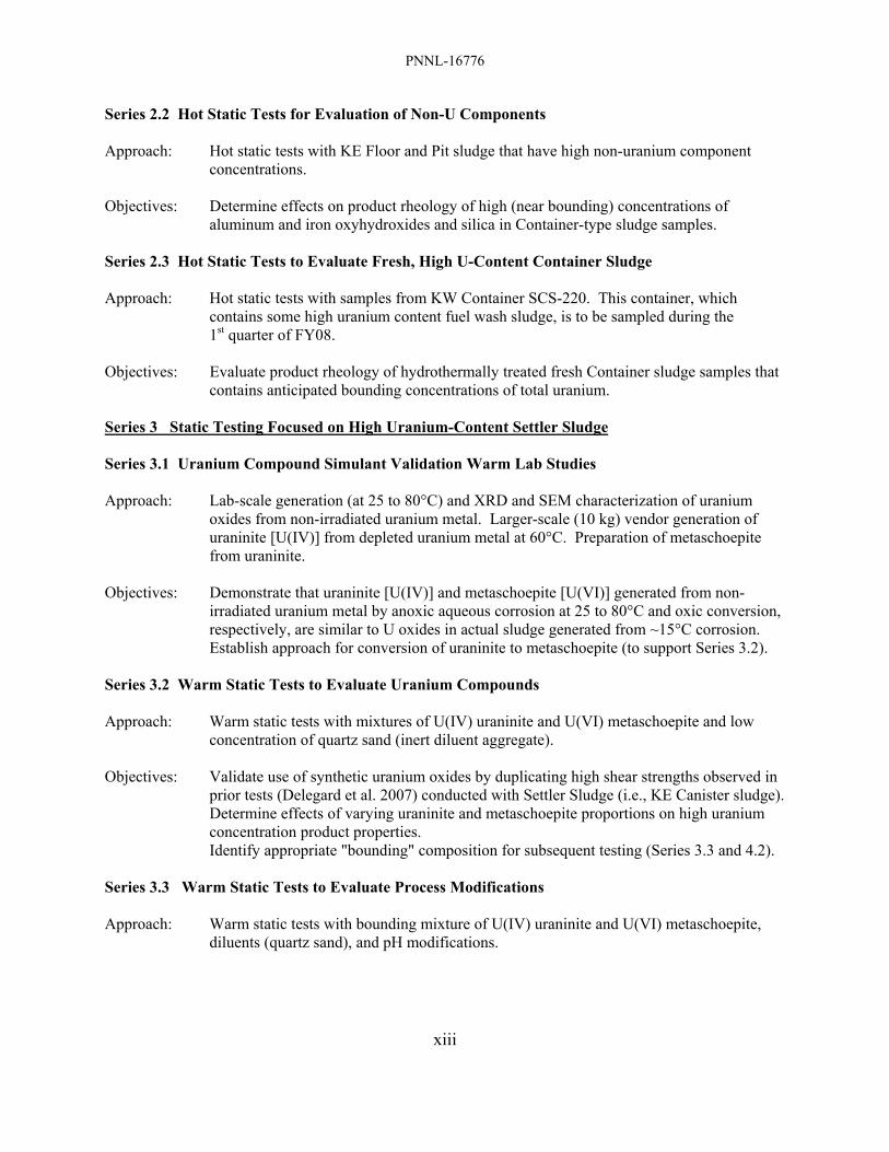
Series 2.2 Hot Static Tests for Evaluation of Non-U Components Approach: Hot static tests with KE Floor and Pit sludge that have high non-uranium component
concentrations. Objectives: Determine effects on product rheology of high (near bounding) concentrations of
aluminum and iron oxyhydroxides and silica in Container-type sludge samples. Series 2.3 Hot Static Tests to Evaluate Fresh, High U-Content Container Sludge Approach: Hot static tests with samples from KW Container SCS-220. This container, which
contains some high uranium content fuel wash sludge, is to be sampled during the 1st quarter of FY08.
Objectives: Evaluate product rheology of hydrothermally treated fresh Container sludge samples that
contains anticipated bounding concentrations of total uranium. Series 3 Static Testing Focused on High Uranium-Content Settler Sludge Series 3.1 Uranium Compound Simulant Validation Warm Lab Studies Approach: Lab-scale generation (at 25 to 80°C) and XRD and SEM characterization of uranium
oxides from non-irradiated uranium metal. Larger-scale (10 kg) vendor generation of uraninite [U(IV)] from depleted uranium metal at 60°C. Preparation of metaschoepite from uraninite.
Objectives: Demonstrate that uraninite [U(IV)] and metaschoepite [U(VI)] generated from non-
irradiated uranium metal by anoxic aqueous corrosion at 25 to 80°C and oxic conversion, respectively, are similar to U oxides in actual sludge generated from ~15°C corrosion.
Establish approach for conversion of uraninite to metaschoepite (to support Series 3.2). Series 3.2 Warm Static Tests to Evaluate Uranium Compounds Approach: Warm static tests with mixtures of U(IV) uraninite and U(VI) metaschoepite and low
concentration of quartz sand (inert diluent aggregate). Objectives: Validate use of synthetic uranium oxides by duplicating high shear strengths observed in
prior tests (Delegard et al. 2007) conducted with Settler Sludge (i.e., KE Canister sludge). Determine effects of varying uraninite and metaschoepite proportions on high uranium
concentration product properties. Identify appropriate "bounding" composition for subsequent testing (Series 3.3 and 4.2). Series 3.3 Warm Static Tests to Evaluate Process Modifications Approach: Warm static tests with bounding mixture of U(IV) uraninite and U(VI) metaschoepite,
diluents (quartz sand), and pH modifications.
PNNL-16776
xiv
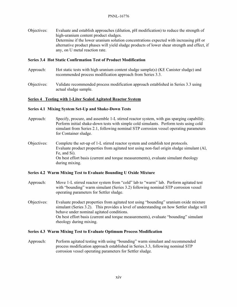
Objectives: Evaluate and establish approaches (dilution, pH modification) to reduce the strength of high-uranium content product sludges.
Determine if the lower uranium solution concentrations expected with increasing pH or alternative product phases will yield sludge products of lower shear strength and effect, if any, on U metal reaction rate.
Series 3.4 Hot Static Confirmation Test of Product Modification Approach: Hot static tests with high uranium content sludge sample(s) (KE Canister sludge) and
recommended process modification approach from Series 3.3. Objectives: Validate recommended process modification approach established in Series 3.3 using
actual sludge sample. Series 4 Testing with 1-Liter Scaled Agitated Reactor System Series 4.1 Mixing System Set-Up and Shake-Down Tests Approach: Specify, procure, and assemble 1-L stirred reactor system, with gas sparging capability.
Perform initial shake-down tests with simple cold simulants. Perform tests using cold simulant from Series 2.1, following nominal STP corrosion vessel operating parameters for Container sludge.
Objectives: Complete the set-up of 1-L stirred reactor system and establish test protocols. Evaluate product properties from agitated test using non-fuel origin sludge simulant (Al,
Fe, and Si). On best effort basis (current and torque measurements), evaluate simulant rheology
during mixing. Series 4.2 Warm Mixing Test to Evaluate Bounding U Oxide Mixture Approach: Move 1-L stirred reactor system from “cold” lab to “warm” lab. Perform agitated test
with “bounding” warm simulant (Series 3.2) following nominal STP corrosion vessel operating parameters for Settler sludge.
Objectives: Evaluate product properties from agitated test using “bounding” uranium oxide mixture
simulant (Series 3.2). This provides a level of understanding on how Settler sludge will behave under nominal agitated conditions.
On best effort basis (current and torque measurements), evaluate “bounding” simulant rheology during mixing.
Series 4.3 Warm Mixing Test to Evaluate Optimum Process Modification Approach: Perform agitated testing with using “bounding” warm simulant and recommended
process modification approach established in Series.3.3, following nominal STP corrosion vessel operating parameters for Settler sludge.

PNNL-16776
xv
Objectives: Evaluate product properties from agitated testing using recommended process modification approach established in Series 3.3. This provides a level of understanding on how Settler sludge, with recommended process modifications, will behave under nominal agitated conditions.
On a best effort basis (current and torque measurements), evaluate “bounding/modified” simulant rheology during mixing.
Series 4.4 (Optional) Hot Mixing Test to Evaluate Optimum Process Modification Approach: Based on project direction, Series 4.3 may be repeated using actual high-uranium content
sludge samples. This will require moving and operating the agitated test system into the hot cells.
Objectives: Demonstrate, if required, the behavior of actual sludge samples under prototypic heated
and stirred process conditions.

PNNL-16776
xvii
Contents
Forward ......................................................................................................................................................... ii Summary ...................................................................................................................................................... iii Terms and Acronyms................................................................................................................................. xxi 1.0 Introduction................................................................................................................................... 1.1 2.0 Data Quality Objectives................................................................................................................ 2.1 2.1 Identification of the Problems to be Addressed .................................................................. 2.1 2.2 Identification of Decisions .................................................................................................. 2.2 2.3 Data Input to Address Decisions......................................................................................... 2.3 2.4 Use of Data – Decision Rules ............................................................................................. 2.5 3.0 Test Description............................................................................................................................ 3.1 3.1 Test Series 1.1, 2.2, 2.3, and 3.4: Small Scale Static Hot Tests ...................................... 3.12 3.2 Test Series 2.1: Evaluate Al, Fe, and Si Phase Sludge Components ............................... 3.13 3.3 Test Series 3.1: Production and Validation of Synthetic Uraninite and Metaschoepite from Depleted Uranium .......................................................................... 3.13 3.4 Test Series 3.2 and 3.3: Small Scale Warm Static Tests with Depleted Uranium .......... 3.13 3.5 Test Series 4.1: Bench-Scale Cold Tests with Agitation and Evaporation ..................... 3.17
3.6 Test Series 4.2, 4.3, and (optional) 4.4: Bench-Scale Tests with Agitation and Evaporation .............................................................................................................. 3.17 3.7 Sludge Containing High Concentrations of Uranium Metal (KOP Sludge) .................... 3.18 4.0 Test Systems ................................................................................................................................. 4.1 4.1 Static Test Systems ............................................................................................................ 4.1 4.2 Stirred Test Systems ........................................................................................................... 4.2 5.0 Test Approach Summary .............................................................................................................. 5.1 6.0 Basis for Test Matrix/Test Parameters.......................................................................................... 6.1 6.1 Test Temperature and Time ................................................................................................ 6.1 6.2 Basis for Test Size and Sludge/Water Concentration ......................................................... 6.2 6.3 Basis for Flocculent Loading .............................................................................................. 6.3 7.0 Description of Sludge Materials for Use in Testing and Test Matrices ........................................ 7.1 7.1 K Basin Sludge Materials for Hot Testing.......................................................................... 7.1 7.2 Test Series 1.1, 2.2, 2.3, and 3.4 and Materials for Hot Testing......................................... 7.5 7.3 Test Series 3.1 and Synthetic Uraninite and Metaschoepite Sludge Materials ................... 7.7 7.4 Test Series 3.2 and 3.3 and Warm Static Testing ............................................................... 7.8 7.5 Test Series 4.1 and Development of Cold Simulants.......................................................... 7.9 7.6 Test Series 4.2 and 4.3 and Warm Stirred Testing............................................................ 7.11

PNNL-16776
xviii
Contents (cont’d) 8.0 Post-Test Analyses........................................................................................................................ 8.1 9.0 References..................................................................................................................................... 9.1 Appendix A, Preliminary Evaluation of Scaled Mixing Test ................................................................... A.1 Appendix B, Determination of Metaschoepite Concentration in Uranium-Rich Sludges from Chemical Composition and Particle Density Data ......................................................B.1 Appendix C, Technical Reviewer Comments – J Abrefah, Pacific Northwest National Laboratory ........C.1 Appendix D, Technical Reviewer Comments – RB Baker, Fluor Hanford.............................................. D.1 Appendix E, Resolution of Reviewer Comments ......................................................................................E.1

PNNL-16776
xix
Figures
S.1 Test Matrix and Logic Outline........................................................................................................ ix 3.1 Series 1 Benchmark Testing Logic at New STP Operating Temperature..................................... 3.1 3.2 Series 2 Static Testing Focused on Container Sludge................................................................... 3.2 3.3 Series 3 Static Testing Focused on Settler Sludge........................................................................ 3.3 3.4 Series 4 Testing with 1-Liter Scaled Stirred Reactor.................................................................... 3.4 3.5 Test Matrix Outline....................................................................................................................... 3.5 3.6 Solubility of Metaschoepite, UO3·2H2O, at 25°C....................................................................... 3.14 3.7 Activity-Activity Diagram for the System CO2-CaO-UO3-H2O................................................. 3.15 3.8 Activity-Activity Diagram for the System SiO2-CaO-UO3-H2O................................................ 3.15 4.1 Small-Scale Static Test Vessel Diagram....................................................................................... 4.1 4.2 Stirred Test Vessel Diagrams Based on Parr Model 4523 with O-Ring Gasket........................... 4.3 6.1 Target Vessel Temperature Profile for Processing Container Sludge .......................................... 6.2 7.1 Composition of KE Floor and Pit Sludges and Their Average..................................................... 7.3
7.2 Compositions of Candidate Sludges for Future Testing ............................................................... 7.3
7.3 Compositional Diagram of Cold Test Mixtures.......................................................................... 7.11
A.1 Process Vessel Diagram and Test Vessel Diagram ..................................................................... A.1
A.2 Standard Parr Design for Dished-Bottom Reactor....................................................................... A.2
A.3 Density and Viscosity of Water as a Function of Temperature (°C) ........................................... A.5 A.4 Agitation Levels for Process-Scale and Bench-Scale Stirred Vessels at “Chemineer” Agitation Level 5 ............................................................................................... A.5
B.1 UO2.x Density as a Function of Stoichiometry ..............................................................................B.2

PNNL-16776
xx
Tables
S.1 Test Matrix Summary ...................................................................................................................... x 2.1 Cross Reference between Problems, Decisions, and Inputs ......................................................... 2.5 3.1 Mapping of Tests to Problems ...................................................................................................... 3.1 3.2 Test Series Approach and Objectives ........................................................................................... 3.8 3.3 Test Materials and Conditions .................................................................................................... 3.10 6.1 Operating Parameters for the STP Corrosion Process .................................................................. 6.1 6.2 Projected Flocculent Concentrations in Settled Sludge ................................................................ 6.3 7.1 Compositions of Candidate Hot Test Sludge Sample Materials................................................... 7.4 7.2 Small Scale Static Hot Test Materials and Matrix ........................................................................ 7.5 7.3 Small Scale Static Warm 150°C Matrix for Test Series 3.2 and 3.3 ............................................ 7.8 7.4 Small Scale Static Cold Test Matrix ........................................................................................... 7.10 8.1 Sequence of Post-Test Analysis Steps for Each Test Vessel and Rationale ................................. 8.1 A.1 Dimensional Comparison of the STP Corrosion Process Reactor with the Bench Test Vessel.......................................................................................................... A.3 A.2 Target Features for Laboratory Scale Reactor Vessel ................................................................. A.3 A.3 Chemineer Scale for Agitation of Solids in Suspension .............................................................. A.4 B.1 KC-2/3 M250 Sludge in 1999.......................................................................................................B.3 B.2 KC-2/3 M250 Sludge Before Hydrothermal Testing in 2006.......................................................B.4 B.3 KC-2/3 M250 Sludge After Hydrothermal Testing in 2006 .........................................................B.5 E.1 Disposition of Comments from John Abrefah ..............................................................................E.1 E.2 Disposition of Comments from Ron Baker...................................................................................E.3
PNNL-16776
xxi
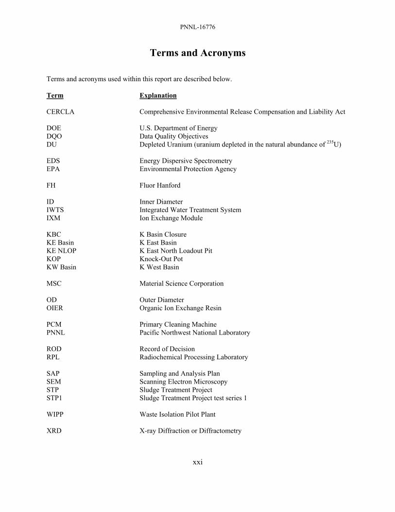
Terms and Acronyms Terms and acronyms used within this report are described below. Term Explanation CERCLA Comprehensive Environmental Release Compensation and Liability Act DOE U.S. Department of Energy DQO Data Quality Objectives DU Depleted Uranium (uranium depleted in the natural abundance of 235U) EDS Energy Dispersive Spectrometry EPA Environmental Protection Agency FH Fluor Hanford ID Inner Diameter IWTS Integrated Water Treatment System IXM Ion Exchange Module KBC K Basin Closure KE Basin K East Basin KE NLOP K East North Loadout Pit KOP Knock-Out Pot KW Basin K West Basin MSC Material Science Corporation OD Outer Diameter OIER Organic Ion Exchange Resin PCM Primary Cleaning Machine PNNL Pacific Northwest National Laboratory ROD Record of Decision RPL Radiochemical Processing Laboratory SAP Sampling and Analysis Plan SEM Scanning Electron Microscopy STP Sludge Treatment Project STP1 Sludge Treatment Project test series 1 WIPP Waste Isolation Pilot Plant XRD X-ray Diffraction or Diffractometry

PNNL-16776
1.1
Sludge Treatment Project Corrosion Process Chemistry Follow-on Testing
1.0 Introduction This test plan describes the scope and conditions to be used to perform laboratory-scale testing of the hydrothermal treatment of K Basin sludge. The proposed testing builds on the approach and laboratory test findings for both K Basin sludge and simulated sludge garnered during testing from September 2006 to March 2007 (Schmidt et al. 2006; Delegard et al. 2007). The planned testing is designed to yield further understanding of the nature of the chemical reactions, the effects of compositional and process variations and the effectiveness of various strategies to mitigate the observed high shear strength phenomenon observed by Delegard et al. (2007). This plan aligns with the identified objectives developed for the K Basins Sludge Treatment Project (STP) in the related Data Quality Objectives (DQO) document (Makenas and Schmidt 2007) and incorporates the testing recommendations from the “Report on Expert Review of the Sludge Treatment Project Testing” (Abrefah et al. 2007). The testing campaign is considered a post-ROD (record of decision) treatability study under CERCLA (Comprehensive Environmental Release Compensation and Liability Act) and conducted using guidance contained in EPA Guidance for Treatability Studies under CERCLA (EPA 1992). The sludge currently found in the water-filled Hanford K Basins is a mixture of particulate materials including irradiated metallic uranium fuel, fuel corrosion products, wind borne soil, filter sand, corrosion products from racks (iron and aluminum), canisters (aluminum), and walls (concrete), spilled organic and inorganic Ion Exchange Module (IXM) media (mixed bed cation/anion resin and mordenite), and other minor constituents. By project definition, K Basin sludge is defined as any particulate material that can pass through a screen with 0.25-inch openings (Schmidt 2006). The K Basins sludge is being managed as three distinct sludge streams: Container sludge, Settler Tank (Settler) sludge, and Knock-out Pot (KOP) sludge. The majority of the sludge, Container sludge (~41 m3), is being consolidated in the basins into large rectangular containers in the K West (KW) Basin, each which can hold up to 11.6 m3). Container sludge consists of sludge from the K East (KE) and KW Basin floors and pits along with smaller volumes of sludge from the KE fuel storage canisters and sludge from fuel washing. All primary KE and KW fuel (and fuel storage canisters) were washed in the Primary Cleaning Machine (PCM) located in the KW Basin. In addition to fuel washing, canister cleaning and scrap sorting operations occurred in the KW Basin. Sludge generated from these operations was vacuumed into the Integrated Water Treatment System (IWTS). During fuel washing, pieces of material larger than 0.25 inch (6350 µm) are removed in strainers (i.e., because of its particle size, strainer material is not considered sludge). Next, in the IWTS, larger sludge particles (~500 to 600 μm up to 6350 µm) are retained in KOPs, which include internal or external filters. Total KOP sludge volume is ~0.26 m3. After passing through the KOPs, the IWTS sludge stream enters the Settler Tanks (ten parallel 20-inch diameter, 16-ft long tanks), where the finer particulate sludge (<500/600 µm) is allowed to settle. Total Settler sludge volume is ~5.4 m3. The accepted physical and chemical characteristics of the sludge are given in the design basis feed documents and in the sludge data book (Pearce 2001; Schmidt 2006; Plys and Schmidt 2006). Sludge sampling and laboratory analysis campaigns started in 1995 and have been performed to acquire specific

PNNL-16776
1.2
characterization data for disposition of this sludge inventory. Results of these campaigns are documented (Pitner 1999; Makenas et al. 1996, 1997, 1998; Baker and Welsh 2001). The current proposed hydrothermal processing campaign is entirely separate from the completed parallel effort to grout K East Basin North Load Out Pit sludge (without an oxidation/corrosion step) at the Hanford T Plant. The three sludge types are to be sequentially treated within the STP process to create a grouted product acceptable for shipment to WIPP (the Waste Isolation Pilot Plant). Part of this process includes reaction of sludge, including its contained metallic uranium fuel particles, in liquid water at (nominally) 150°C(a) and ~87 psig (5.9 atm). The objective of the processing is to convert metallic uranium completely into uranium oxides and thus preclude the formation of additional hydrogen during shipment to the WIPP through the corrosion reaction of uranium metal with water. As part of the nominal uranium metal corrosion process, as-settled sludge will be diluted with water (the extent of dilution is established for each of the three sludge types) and mechanically agitated. Design details and end points of the production-scale oxidation process have been provided by Woodworth (2006) and the operation temperature provided by the STP.(b) An independent review panel for the STP pointed to several concerns with the sludge corrosion process and noted that the smaller-scale demonstrations, which are normally undertaken to validate new processes, had not been performed for corrosion step (Heywood 2006). Subsequently, five tests (using actual sludge samples) were conducted in the first half of FY 2007 to examine the chemical and physical properties of sludge processed under the nominal STP process conditions (Delegard et al. 2007). Parameters evaluated included the effects of sludge composition, the presence of irradiated uranium metal fuel from the N Reactor, the presence of flocculating agent, and the presence of organic ion exchange resin (OIER). The tests were each conducted with ~50-ml of settled sludge without agitation for ~7 to 72 hours at 185°C. The two sludge formulations tested represented nominal (vs. bounding) compositions of the two major sludge streams (Settler and Container) to be fed to the STP process. These tests were designed to specifically evaluate chemical and physical behavior aspects of the process but not engineering aspects. The tested sludges were representative of the high uranium concentration sludge arising from Settler Tubes (~5.4 m3) and the lower uranium concentration sludge collected in containers in the K Basins (Container sludge; ~41 m3). The STP process characteristics of the third type of sludge found in Knock-Out Pots (KOP sludge; ~0.26 m3) were not studied because of its limited volume (~0.26 m3), planned high dilution with water during processing, and favorable experience with processing uranium metal-rich sludge in prior hydrothermal testing at up to 95°C (Schmidt et al. 2003). Two of the five experiments were performed with high uranium content sludge (~70 wt% uranium, dry basis) representative of Settler tube sludge and contained irradiated uranium metal particles. The tests were conducted according to STP process conditions of 7 to 10 hours at 185°C. The uranium metal (a) The lower temperature (150°C) and associated pressure (87 psig) is new guidance from the Sludge Treatment
Project. The nominal operating temperature for the corrosion step formerly was 185°C with 225 psig operating pressure. The temperature decrease increases reaction time by a factor of ~4.4 according to the uranium metal anoxic aqueous corrosion rate law, log10 rate, μm/h = 9.694 – 3565/T (T in K) determined from review of the technical literature (Appendix G of Plys and Schmidt, 2006). With this rate equation, the reaction time to extinction of a ¼-inch (6350-μm) diameter uranium metal particle is 39 hours at 185°C and 171 hours at 150°C while the extinction time of a 600-μm maximum diameter uranium metal particle characteristic of Settler tube sludge is 16 hours at 150°C. The 185°C reaction times were based on the former reaction rate law (log10 rate, μm/h = 8.224 – 3016/T), which projects a 72-h extinction time for a ¼-inch diameter particle.
(b) Memorandum (draft) 07-STP-NJS-004, NJ Sullivan to DG Ruscitto, June 7, 2007, “Sludge Treatment Project Technical Services Recommendation Regarding DOE Direction to Reduce Corrosion System Temperature and Pressure,” Fluor Hanford, Richland, WA.

PNNL-16776
1.3
converted to UO2.x by corrosion in the water. The hydrothermal treatment decreased the settled sludge volume in both tests by about 20% to yield more free (supernatant) water, likely by dehydration of metaschoepite, a U(VI) mineral present in the sludge, to form dehydrated schoepite and reaction of metaschoepite with silica to form soddyite. Most importantly, the sludge products from the static tests had shear strengths of 120,000 to 170,000 Pa (assessed as “very stiff” according to soil physics descriptions). These strengths represented sharp increases from the shear strengths of similar untreated sludge which range from about 270 to 8100 Pa (described as “fluid mud” to “very soft”). The three remaining experiments used a composite of sludge samples representative of Container sludge and had lower (~16 wt%, dry basis) uranium. The sludge was reacted according to STP process conditions for ~72 hours at 185°C. The three test product solids were significantly softer, 9,000 to 16,000 Pa (“very soft” to “soft”) than those produced by the tests representing Settler sludge. Tests performed with and without added irradiated uranium metal fuel particles, flocculating agent, and OIER showed that none of these components had a significant impact on product sludge strength. Unlike the Settler sludge, the water content of the product Container sludge was not significantly affected by the processing. Water erosion test results (used to evaluate the apparent cohesiveness of the post-test product), performed for four of the five products, were consistent in trend with the shear strength measurements (the fifth product was too soft to test by water erosion). The products higher in shear strength were found to be more resistant to water erosion. The adherence of the sludge products to the Teflon vessel walls also was found qualitatively to increase with increased shear strength. The reasons for the sharply higher strengths of the Settler sludge compared with the Container sludge are not known with certainty. The higher strength may be because of the higher uranium concentration in the Settler sludge. Other instances of uranium-rich high strength sludge materials include the creation of a strong agglomerate of KE canister sludge by ~33°C storage in the hot cell and the strong concretion observed for the starting KC-2/3 M250 sludge used in the hydrothermal testing (Delegard et al. 2007).(a) This latter sludge, also obtained from fuel canisters in the KE Basin, could not be removed from its hot cell storage jar by ordinary tools (e.g., spatulas) but could only be retrieved by breaking the jar and extracting the sludge as a single piece. In another example of sludge hardening under water-saturated conditions, significant physical resistance was encountered at 13 inches and 10 inches from the floor while driving an isolation tube (a pipe) into the ~36-inch thick sludge layer of uranium-poor K East Basin North Loadout Pit in December 2003 during a sampling operation. The resistance may have indicated that the sludge hardened at this level (Mellinger et al. 2004), though this resistance could have been in-part caused by buried debris in the sludge as well in some instances. Other instances of sludge self-cementation (hardpans) have been encountered during K Basin sludge retrieval operations. Sludge adhesion on vessel walls, noted in the recent tests with Teflon vessels, also has been observed in prior hydrothermal reaction tests, conducted from 60 to 95°C in stainless steel vessels, of floor sludge containing uranium metal particles (Schmidt et al. 2003). After reaction, this sludge contained 50.2 wt% uranium (dry basis) and also contained 5.4 wt% aluminum, 8.9 wt% iron, and 2.5 wt% silicon and thus has composition intermediate between the Settler and Container sludge types tested in FY 2007.
(a) Though not mentioned explicitly in Delegard et al. (2007), this refers to the behavior of KE canister sludge
sample 96-13 following 28½ months of settling in a graduated cylinder in the hot cell (Delegard et al. 2005). This case, however, did involve a sample that had dried during storage and was re-wetted and reconstituted.
PNNL-16776
1.4
Considerations into further testing to answer chemistry and engineering/design questions and thus support the STP processing are the focus of this Test Plan and were advanced in the prior report (Section 4.0 of Delegard et al. 2007). The problems were considered further under a DQO framework to help define potential avenues of experimental study, identify test limitations, and understand the decisions arising from application of the test findings (Makenas et al. 2007a). In parallel with the DQO process, an independent expert panel review of the prior testing (Delegard et al. 2007) and the proposed follow-on testing was conducted on April 26, 2007 (Abrefah et al. 2007). The DQO process and the expert panel recommendations are described in Section 2.0 of this Test Plan. The broad test matrix and specific test objectives are described in Section 3.0. The test equipment and testing approach are discussed in Sections 4.0 and 5.0. The technical justifications for the test matrix and specific test parameters are given in Section 6.0. Section 7.0 includes discussion and descriptions of the sludge material that will be used in the testing and describes in further detail the matrices of experiments with K Basin sludge, simulated sludge containing uranium phases (uraninite and metaschoepite), and completely non-radioactive simulated sludge designed to determine the effects of sludge composition on sludge product properties. The planned examinations and characterization activities that will be conducted on the treated sludge samples resulting from the tests are outlined in Section 8.0. Appendix A describes the approach used to design and derive full-scale mixing performance from lab-scale mixing tests. Appendix B describes calculations to determine the concentrations of metaschoepite in uranium-rich sludges based on chemical composition and particle density data. Appendices C and D present independent technical reviewer comments obtained from John Abrefah and Ronald B. Baker, respectively. Appendix E details the resolutions made to the technical reviewer comments.
PNNL-16776
2.1
2.0 Data Quality Objectives Environmental Protection Agency (EPA) guidance for treatability studies (EPA 1992) indicates that formulation of DQOs is the first of eleven steps in performing such a study. Characterization campaigns for both fuel and sludge from K Basins have in the past been governed by a set of formal DQOs (for example Makenas 1998, 1999, 2000). The DQO methodology followed in this document is that defined in the K Basin Project DQO Strategy Document (Lawrence 1994) with the various standard DQO questions addressed in sequence in the following discussions. The reference strategy document is based on EPA guidance (EPA 1994) but it notes the parts of the process which must be modified for a project, such as K Basin Closure (KBC), which seeks to determine bounding conditions to select design, transportation, and mitigation alternatives. The study described by the current document is limited to problems and data needs identified under the DQO for Sludge Treatment Project Laboratory Testing (Makenas and Schmidt 2007), which was based primarily on the early set of Pacific Northwest National Laboratory (PNNL) process tests results (Delegard et al. 2007) and STP process criteria. Recommendations by a recent expert review panel (Abrefah et al. 2007) provided further guidance in the development of the current test approach. Broader issues with respect to acceptance of the grouted sludge at WIPP and nuclear accountability of sludge in K West Basin tanks are being addressed in separate DQO documents. Individual steps in the DQO process, Identification of the Problems, Identification of Decisions, Data Input to Address Decisions, and Use of Data – Decision Rules are described in Sections 2.1, 2.2, 2.3, and 2.4, respectively. The DQO process rationale is largely derived from the analysis provided by Makenas (2007a). 2.1 Identification of the Problems to be Addressed The primary goal of the STP is to oxidize contained uranium metal and thus eliminate chemical generation of hydrogen gas by reaction of uranium metal with water in anticipation of sludge disposal to the WIPP. Most of the literature data available on uranium oxidation rates in water (Trimble 1998, Ritchie 1981) used in prior K Basin studies are at temperatures lower than that of the anticipated STP process. A comprehensive review of the rate data now exists, better encompassing the process temperature (Appendix G of Plys and Schmidt 2006). Data on reaction rates for K Basin sludge (albeit at <100°C) also are available in recent studies based on hydrogen and fission product gas release rates (Delegard et al. 2000, Bryan et al. 2004, Schmidt et al. 2003). Evidence that sludge blanketing may decrease oxidation rates was found in these latter studies. The studies also show that at low uranium metal concentrations, some of the hydrogen product does not appear in the gas phase and thus must be consumed by sludge constituents. This may be of concern if monitoring of the progress of the uranium metal reaction in the actual STP equipment will be done by measuring hydrogen in the released gas phase and gives evidence of other reactions that may be occurring in the hydrothermal sludge system. Besides uranium metal, sludge contains a number of non-uranium constituents and uranium compounds which may dissolve to greater extent at the process temperature. Thus, new phases may form at process temperature, by precipitation through loss of water in the envisioned nitrogen gas sparge and by subsequent cooling of the process product to ambient temperature, to cement particles together. Laboratory samples of sludge have hardened in storage at ~30°C hot cell temperature. Sludge contains a variable quantity of organic materials including ion exchange resin beads, which have been shown previously to be relatively stable at temperatures <100°C, and flocculating agents, that have also been added to the sludge during some K Basin operations. The initial phase of 185°C process testing at PNNL
PNNL-16776
2.2
(Delegard et al. 2007) suggests that the resin beads, flocculant, and the presence of uranium metal do not affect Container sludge product strength. However, high uranium content sludge, such as that to be found in the Settler tanks, produced products with unacceptably high shear strength that would not be readily transportable from the STP process vessel (in a loss-of-agitation event) for the follow-on grout emplacement activities. The nitrogen sparge gas, the entrained water vapor, and the escape of hydrogen during oxidation have the potential to foam the sludge. This could have adverse consequences in that the sludge level will be hard to measure, sludge particulate can be transported by the foam to unanticipated locations, and components such as HEPA filters can be wetted. If foaming does occur in significant quantity, then the process design will have to make allowances that are greater than those currently anticipated. The effects of change in the process temperature from 185°C to 150°C also must be taken into account. This Test Plan will emphasize the effects of sludge composition variability and STP process conditions on the product properties. The problems in attaining successful treatment are:
1. The sludge treatment process must be able to recover from off-normal conditions such as the loss of agitation during or after the processing. The formation of a high shear strength product may affect the ability to recover from a loss-of-agitation incident.
2. The formation of a high shear strength product occurs at specific but unknown compositions and temperatures. The chemical reactions and the product phases which form during normal and off-normal processing are not well known and there is little understanding of the mechanisms by which these phases affect sludge product properties, particularly strength.
3. The sludge treatment process might produce a high shear strength product that has unacceptable handling characteristics even under normal operating conditions.
4. Sludge has been observed in previous tests to cling to Teflon test reaction vessel walls. Materials adhering to the stainless steel process vessel walls may degrade process performance such as wall heat transfer or adversely affect vessel emptying operations.
5. Although the temperature variations in the process are expected to be small, process interruptions can cause temperature cycling. The process vessel also will carry over a heel between batches. The effects of multiple thermal cycling of sludge are not known.
6. Gas retention (primarily hydrogen) in the product sludge varies significantly as shown by the initial non-agitated laboratory process tests. It is not known whether this will occur under agitated conditions and whether it will affect subsequent sludge handling and processing.
7. The sludge state during processing could affect the functioning of the demister in the processing containers through particulate transport by foam formation or bubble breakage.
2.2 Identification of Decisions The decisions which must be made by the KBC project with respect to sludge processing and which are partially addressed by this Test Plan are given in the following list. Decisions may be pursued independently or in parallel.

PNNL-16776
2.3
1. Is the high shear strength phenomenon a dominant or rare occurrence for off-normal loss of agitation in the bulk sludge process? Is the effect applicable to sludge compositions which are outside of the range of the previous laboratory process tests?
2. Can enough understanding of the high shear strength phenomenon be gained to show that the process design is adequate given the anticipated variability in sludge composition and properties? Can the dominant factors in affecting the shear strength be determined?
3. Is the large scale process sufficiently robust during normal operation to handle the high shear strength characteristic of sludge without redesign or further characterization? Can a scaling factor be developed to allow extrapolation of laboratory data to final design performance?
4. Is the laboratory observation of sludge clinging to vessel walls (after processing) applicable to stainless steel vessels at prototypic temperatures? What is the likely extent (thickness) of the coating?
5. Do process and sludge composition variability produce conditions beyond the currently analyzed design envelope?
6. Is hydrogen retention significant enough to affect grout formation or process monitoring?
7. Can the large scale process system be adequately maintained in working order when confronted with sludge particle physical characteristics?
Recommendations for the follow-on testing, made separately by the Expert Review Panel (Abrefah et al. 2007) list experiments explicitly, and were taken into account in formulating this Test Plan. The recommendations, quoted below, may be performed at different temperatures if dictated by nuclear safety reasons:
• “Static trials on container sludge with typical uranium concentrations and enhanced Si, Al, Fe concentrations to determine the level of aggregation compared to other Container sludge samples.
• Static trials with uranium oxides (generated from depleted uranium metal) to simulate and better understand the behavior of high concentration uranium content sludges.
• Static trials to investigate the blending of high U samples with inert materials and solid loading.
• Static hot test to confirm dilution/blending strategies. • Larger scale stirring tests (with uranium surrogate material) as programmed in the current
process design trials. • Hot stirred trials in a Parr reactor for high U material (KOP and Settler Sludge).”
2.3 Data Input to Address Decisions Information to address the problems on sludge behavior under nominal process conditions and decisions listed above will come from laboratory scale tests and the chemical and physical analyses connected with the tests. Multiple tests will be conducted using closed reaction vessels similar in design and operation to those used in prior gas generation (Delegard et al. 2000, Bryan et al. 2004, Schmidt et al. 2003) and STP process studies (Delegard et al. 2007) with the principal exception that for most tests, the goal 150°C STP process temperature will be used. Unlike the more recent STP tests conducted with Teflon-lined vessels

PNNL-16776
2.4
(Delegard et al. 2007), the vessel walls contacting the sludge will be stainless steel to provide reactor wall sludge adherence data prototypical of the process. Limited tests in larger vessels will be performed with stirring to provide information useful to validate the nominal process in accord with recommendations by Abrefah and colleagues (2007). Capability will be available in the larger apparatus to extract water from the system while at high temperature to simulate the dewatering that occurs in the nitrogen-sparged process system. The test apparatus are described in more detail in Section 4.0. Three test types, identified as “cold,” “warm,” and “hot,” will be performed. The “cold” tests will use non-radioactive sludge components (i.e., phases of aluminum, iron, and silicon but not uranium) and may be performed in non-radiological facilities. “Warm” tests will use non-irradiated depleted and natural uranium and will be performed in radiological fume hoods; “hot” tests will be performed in hot cells using K Basin sludge. The K Basin sludges and the surrogates are described in Section 7.0 and the test strategy is described in Section 3.0. This strategy recognizes that the quantities of K Basin sludge samples currently archived are limited and explains the use of non-radioactive or slightly radioactive (non-irradiated) surrogates in place of actual sludge. A cross reference between problem, decisions, and planned experimental inputs is shown in Table 2.1. The K Basin sludge to be used in the testing will be from archive material obtained by the KBC/STP and maintained in the PNNL hot cell facilities. Although no new sludge materials are being collected from K Basin at this time for this process testing campaign, sampling of KW Basin floor sludge from a KW Container is planned by the STP for nuclear material safeguards objectives (Makenas 2007) and excess sludge from this sampling will be tested as judged desirable by the STP.

PNNL-16776
2.5
Table 2.1. Cross Reference between Problems, Decisions, and Inputs Problem Decision(s) Inputs
1. High sludge shear strength observed in process tests may affect off-normal operation
Is the effect a dominant or rare occurrence for off-normal loss of agitation in the bulk process? Is it applicable to varying sludge compositions that are outside the range of the previous tests?
Static small scale warm and limited hot tests. Compositional envelope same as #2 below. More data points to be obtained than in previous tests.
2. We have neither a complete understanding of chemistry and phases nor understanding of their effects on sludge physical properties.
Can one gain enough understanding to show that the design is adequate given the anticipated spread in sludge composition and properties? Can the dominant factors in the shear strength changes seen previously be determined?
Static small scale warm tests with known U phases and process modifications (temperature, pH, etc.). Static small scale hot tests with individual vs. composite samples and with process modifications. Static small scale cold tests with non-U phases can be incorporated but lead to extensive test matrix.
3. High sludge shear strength observed in process tests may affect normal operation.
Is the large-scale process robust enough to handle high strength sludge without further redesign or characterization? Can a scaling factor be determined to allow extrapolation of lab data to final design performance?
Ambient temperature, moderate scale hot agitated test. Full-scale or moderate scale agitated (1 to 8 liter) warm test (with simulant developed in #2 above). Agitated small scale hot testing (with evaporation). Shear stress vs. shear rate by stirring power meas. or standard lab technique (cold test).
4. Sludge clings to walls in testing.
Is the effect real for stainless steel walls and prototypic temperatures and is it applicable to the process? What is the likely extent (thickness)?
Full-scale or moderate scale (1 to 8 liter) warm test (with simulant developed in #2 above). Agitated small scale hot testing (with evaporation). Static small scale warm and hot tests with controlled wall temperature. At multiple temperatures to assess whether temperature is a significant factor.
5. The process varies. Process interruptions cycles temperature. Accumulated heel may be affected.
Does the sum of both process and sludge variability result in a condition outside of the currently analyzed design envelope?
Testing similar to # 2 and #3 above but with multiple temperature cycles added.
6. Gas retention varies in static laboratory process tests.
Is hydrogen retention significant enough to affect grout formulation or process monitoring?
Small scale agitated warm testing. Physical measurements are sufficient to close the issue (without gas sampling).
7. Sludge might affect the functioning of demister in the process containers through particulate transport during foam formation or bubble breakage.
Can the large-scale system be adequately maintained in working order when confronted with known sludge particle characteristics?
Evaluate composition of water from previous tests and of evaporator collection from new tests.
Note : Changes in process temperature or allowable blending of sludge streams may affect the test matrix.
2.4 Use of Data – Decision Rules Preliminary rules developed within the DQO process are given below for the decisions to be made by the STP based on the test results. These preliminary rules are part of a larger decision for the ultimate disposition of sludge and may need to be adjusted based on evolving project priorities.
PNNL-16776
2.6
1. If the shear strengths determined by the static process tests are outside that anticipated by the vendor design, process or compositional changes (e.g., dilution) will be pursued with the system vendor. If the shear strengths are within design expectations, the design will be accepted as sufficient with respect to agitation during off-normal events.
2. If the currently envisioned design adequately supports bulk processing of sludge given the variations in sludge composition, then no action is required. If the design is not adequate to accept sludge compositional variability, process and equipment changes will be considered.
3. If the planned agitation for normal sludge processing proves adequate as demonstrated by laboratory process testing, then further testing will focus only on off-normal events. If the agitation is inadequate for normal sludge processing, more aggressive agitation will need to be added to the bulk process design and the design validated.
4. If the sticking of sludge to the walls of a stainless steel vessel is “significant,” as determined by calculational inputs, then the design specification for the bulk process agitator will be modified. If sludge sticking is not significant, then the agitator design specification will not be modified.
5. If no significant effects of temperature cycling are found, then no operational changes will be made in this arena. If significant effects of temperature cycling are found, operational changes will be made to mitigate the effects (such as maximizing flush and clean out).
6. If gas retention proves to be significant under agitated conditions, then an evaluation will be made of sludge transfers and whether the gas retention creates a bias in the flow meter. If gas retention is not significant, evaluation of its effect on bias of the flow meter will not be made.
7. If the condensate in laboratory scale tests has entrained particulate, then additional calculations will be performed to ascertain the severity of the problem and determine mitigating actions. If entrained particulate is not found in the condensate, no action will be taken.
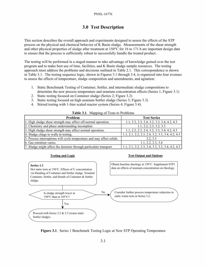
PNNL-16776
3.1
3.0 Test Description This section describes the overall approach and experiments designed to assess the effects of the STP process on the physical and chemical behavior of K Basin sludge. Measurements of the shear strength and other physical properties of sludge after treatment at 150°C for 16 to 171 h are important design data to ensure that the process is sufficiently robust to successfully handle the treated product. The testing will be performed in a staged manner to take advantage of knowledge gained over the test program and to make best use of time, facilities, and K Basin sludge sample resources. The testing approach must address the problems and decisions outlined in Table 2.1. This correspondence is shown in Table 3.1. The testing sequence logic, shown in Figures 3.1 through 3.4, is organized into four avenues to assess the effects of temperature, sludge composition and amendments, and agitation:
1. Static Benchmark Testing of Container, Settler, and intermediate sludge compositions to determine the new process temperature and uranium concentration effects (Series 1; Figure 3.1)
2. Static testing focused on Container sludge (Series 2; Figure 3.2) 3. Static testing focused on high uranium Settler sludge (Series 3; Figure 3.3) 4. Stirred testing with 1-liter scaled reactor system (Series 4; Figure 3.4).
Table 3.1. Mapping of Tests to Problems
Problem Test Series 1. High sludge shear strength may affect off-normal operation. 1.1, 2.2, 2.3, 2.4, 3.2, 3.3, 3.4, 4.2, 4.3 2. Chemistry and phase understanding incomplete. 1.1, 2.2, 2.3, 3.2, 3.3 3. High sludge shear strength may affect normal operation. 1.1, 2.2, 2.3, 2.4, 3.2, 3.3, 3.4, 4.2, 4.3 4. Sludge clings to walls in testing. 1.1, 2.1, 2.2, 2.3, 2.4, 3.2, 3.3, 3.4, 4.2, 4.35. Process interruptions will cycle temperature and may affect solids. 3.2, 3.3 6. Gas retention varies. 1.1, 2.2, 2.3, 3.4 7. Sludge might affect the demister through particulate transport. 1.1, 2.1, 2.2, 2.3, 2.4, 3.2, 3.3, 3.4, 4.2, 4.3
Testing and Logic Test Output and Options
No
Yes
Series 1.1Hot static tests at 150°C. Effects of U concentration via blending of Container and Settler sludge. Nominal Container, Settler, and blends of Container & Settler sludge.
Is sludge strength lower at 150°C than at 185°C?
Consider further process temperature reduction in static warm tests in Series 3.2.
Obtain baseline rheology at 150°C. Supplement STP1 data on effects of uranium concentration on rheology.
Proceed with Series 3.2 & 3.3 (warm static Settler sludge).
Figure 3.1. Series 1 Benchmark Testing Logic at New STP Operating Temperature

PNNL-16776
3.2
Testing and Logic Test Output and Options
Series 2.3Static hot tests at 150°C of sludge from KW Container SCS-220.
Obtain rheological behavior for fresh Container sludges at high (near bounding) total uranium.
Series 2.2Static hot tests at 150°C with KE Floor and Pit sludges having high non-U concentrations.
Obtain rheological behavior for Container-type sludges at high (or near bounding) aluminum & iron oxyhydroxide and sand component concentrations.
Series 2.1Cold static tests at 150°C to mimic predominant non-fuel sludge phases.
Obtain rheological behavior as function of Container sludge compositional variability.Provide comparative data to hot Container sludge Series 2.2.Develop cold simulant for mixing system shake-down testing in Series 4.1.
Figure 3.2. Series 2 Static Testing Focused on Container Sludge

PNNL-16776
3.3
Testing and Logic Test Output and Options
No
Yes
No
Yes
Series 3.1Generate and characterize test-scale uraninite and metaschoepite.
Validate synthetic U(IV) & U(VI) oxide properties against U oxides found in sludge.
Are synth. U oxide particles similar to K Basin sludge particles based on XRD/SEM?
Series 3.2Static warm tests at 150°C.Determine effect of uraninite and metaschoepite.
Identify roles of uraninite and metaschoepite in strength; determine "bounding" (strength) comp's. Compare properties with those of sludge from Series 1.1 and 2.3 tests. Provide input to Series 3.3.
Refine surrogate.
Series 3.3Static warm tests at 150°C. Determine effects of inert dilution and chemical/pH amendments [e.g, CaCO3, Ca(OH)2, phosphate].
Compare surrogate properties with those of sludge from Series 1.1, 2.2, and 2.3 tests. Provide input to Series 3.4.
Do approaches tested in Series 3.3 yield products with acceptable properties?
Consider alternative approaches (other additives, different diluents).
Validate preferred approach to avoid high strength with high U sludge. Provide input to Series 4.3.
Series 3.4Static hot tests of preferred approach for processing high U content (KE Canister) sludge.
Figure 3.3. Series 3 Static Testing Focused on Settler Sludge

PNNL-16776
3.4
Testing and Logic Test Output and Options
Series 4.1Design, test, and demonstrate a stirred reactor using a non-radioactive simulant from Series 2.1.
Produce functional 1-liter stirred reactor, establish test protocols, demonstrate with simulant.On best effort basis, evaluate on-line rheology measurement (using current, torque).
Series 4.2Warm stirred reactor test to evaluate "bounding" uranium oxide simulant from Series 3.2.
Series 4.3Warm stirred reactor test to evaluate "bounding" uranium oxide simulant with optimized approaches developed in Series 3.3.
Produce understanding of Settler sludge behavior under nominal stirred reactor conditions.On best effort basis, evaluate on-line rheology measurement (using current, torque).
Produce understanding of Settler sludge behavior, with process modifications, under nominal stirred reactor conditions.On best effort basis, evaluate on-line rheology measurement (using current, torque).
Series 4.4 (optional)Hot stirred reactor test to evaluate "bounding" genuinesludge with optimized approaches developed in Series 3.3.
Produce understanding of genuine sludge behavior, with process modifications, under nominal stirred reactor conditions.On best effort basis, evaluate on-line rheology measurement (using current, torque).
Figure 3.4. Series 4 Testing with 1-Liter Scaled Stirred Reactor An overview of Test Series 1, 2, 3, and 4 and their interconnecting logic (Figure 3.5) outlines the sequence of testing and testing decision points.

PNNL-16776
3.5
Cold tests
Hot (actual) sludge tests
Warm (depleted uranium) tests
Uranium Compound Simulant Validation (3.1)Establish and validate production of uraninite and metaschoepite compounds generated in lab from depleted uranium for use in follow-on WARM tests.
Al, Fe, & Si Component Evaluation (2.1)Evaluate key non-fuel origin sludge components (Al, Fe, and Si) concentrations and mineral forms.
pH Adjustment and Control (3.3)Evaluate "bounding" uranium mixture properties (as det'd, in 3.2) at varying pH [e.g., CaCO3, Ca(OH)2, phosphate].
Benchmark at New Operating Temperature (1.1)Replicate original tests at lower (150°C) temperature with genuine sludge samples to mimic Settler and Containerized sludge. Evaluate several uranium concentrations. Effects of flocculent and organic ion exchange resin beads will not be tested.
Mixing System Setup (4.1)Establish mixed reactor system and test / demonstrate operational performance with non-radioactive simulant.
Uranium Compound Simulant Dilution Tests (3.3)Evaluate product properties with inert dilution of "bounding" uranium mixture (as determined in 3.2).
Uranium Compound Simulant Testing (3.2) Evaluate effects of varying uraninite and metaschoepite on product properties for high uranium content. Identify bounding composition for subsequent testing. Optionally, identify temperature effects.
Al, Fe, & Si in Container Sludge (2.2)Evaluate effects of high Al, Fe, and Si content with genuine KE Floor and Pit sludge samples.
Mixed Reactor Test (4.2)Evaluate "bounding" uranium mixture determined in 3.2 in mixing reactor.
Confirmation in Mixed Reactor (4.3)Evaluate optimized case uranium mixture (as determined in 3.3) in mixed reactor.
Are synthetic U oxides adequate
based on XRD and SEM?
Acceptable rheology?
Do approaches in 3.3 yield products with acceptable
properties?
Consider alternative test schemes
Further Al, Fe, and Si chemistry understanding required.
No
No
No Yes
Yes
Yes
Confirmation Static Test (3.4)Evaluate optimized case uranium mixture (as determined in 3.3) in static reactor with genuine sludge.
Static Tests with SCS CON 220 Sludge (2.3)Perform hot tests with KW Container 220 samples (should exhibit highest U concentration of all Container Sludge).
Confirmation in Mixed Reactor (4.4 - optional)Evaluate genuine sludge using optimized case treatment (as determined in 3.3) in mixed reactor.
Figure 3.5. Test Matrix Outline
PNNL-16776
3.6
As seen in Figure 3.5, most of the testing will be performed under unstirred (static) hydrothermal conditions. Limited testing, occurring later in the test program using more complex stirred test apparatus, will be performed under Series 4 based on the results of the initial static tests. As shown in Figure 3.5, the testing will be performed using both K Basin sludge samples (so-called “hot” tests) and simulated sludge materials (“warm” and “cold” tests). The initial “hot” tests are designed to investigate the effects of sludge composition and the lower process temperature (150°C versus 185°C previously) on the properties of the product sludge. The Test Series 1.1 and 2.2 are designed, respectively, to investigate the effects of uranium concentration and the effects of high aluminum, iron, and silicon compound concentrations on the product sludge qualities. Test Series 2.3 will investigate the behavior of sludge to be acquired in the first quarter of FY2008 from the KW Container SCS-220. This sludge is expected to contain high uranium concentrations relative to the sludge in other containers. A later “hot” test will be performed under Series 3.4 to test process modifications developed under “warm” testing. Limits on the quantity and variety of K Basin sludge samples in the laboratory but primarily the need to perform parametric testing to investigate the effects of sludge composition, dilution, pH (and other chemical process modifications), and temperature were judged to require the use of simulated sludges in this test program. Simulated sludges will require both non-radioactive (i.e., “cold”) aluminum-, iron-, and silicon-bearing constituents (as identified in Test Series 2.1) and slightly radioactive non-irradiated uranium (as defined in Tests Series 3.1). The uranium compounds used for the “warm” test simulated sludge will include uranium metal, uraninite [nominally UO2.x, a U(IV) phase], and metaschoepite [UO3·2H2O, a U(VI) phase]. These are the three primary uranium phases observed in the K Basin sludge. The preparation and characterization of the uraninite and the metaschoepite constitute Test Series 3.1. The testing with sludges prepared from the non-irradiated uranium materials are called “warm” because the uranium used in these tests are mildly radioactive compared with the K Basins sludge. Test Series 3.2 is designed to investigate the effects of the ratios of the uranium compounds uraninite and metaschoepite on sludge product properties. Test Series 3.3 is designed to determine the effects of uranium concentration with respect to inert diluent (quartz sand) on sludge product properties. The effects of pH modification by use of chemical amendments [CaCO3, Ca(OH)2, and phosphate] also will be investigated within Series 3.3. Test Series 3.2 and 3.3 thus will use “warm” simulated sludges and will be performed under static (non-stirred) conditions. Test Series 4.1 is solely for the design and testing of a 1-liter scale stirred reactor system. The apparatus will be qualified using “cold” simulant(s) identified under Test Series 2.1. On a best effort basis, means to follow sludge rheology dynamically during stirring will be pursued using, for example, on-line current and torque measurement. Stirrer shut-down and re-start with a sludge-loaded vessel will be tested. Test Series 4.2 will use a “warm” simulated sludge whose product behavior is determined under Test Series 3.2 to be “bounding” (i.e., most challenging to processing) under stirred scaled (at 1-liter) process conditions. Test Series 4.3 is similar to Series 4.2 but will use a simulated “bounding” sludge that has been treated by process modifications as indicated by the prior static tests (Series 3.3). Both test series will include a stirrer shut-down, settling, and re-start to help determine if sludge can be remobilized.

PNNL-16776
3.7
In the program for this Test Plan, most experiments will be conducted in small-scale sealed stainless steel reaction vessels under either static (128-ml) or stirred (1-liter) conditions. The use of stainless steel vessels will allow confident prediction of the likelihood of sludge adhesion and caking to the stainless steel process vessel. The static small-scale tests will investigate the effects of sludge composition (including dilution), chemical amendment (pH, addition of other reagents such as CaCO3), and perhaps the effects of temperature on product qualities (strength, water content, gas retention, chemical products). Because of materials availability and relative simplicity, most of the experiments will be small-scale tests. Limited testing in stirred bench-scale (~1-liter) vessels with “warm” sludge also is envisioned to provide data on sludge behavior under agitated conditions. The observed behaviors in the bench-scale tests (e.g., resistance to agitation, evidence of foaming) will aid in confirmation of full-sized process equipment. The “hot” tests using existing samples of K Basin sludge and possibly irradiated N Reactor fuel will be performed in a shielded hot cell. “Warm” tests will be performed using non-irradiated uranium materials prepared under conditions similar, where possible, to those found in the K Basins (Section 7.3 elaborates the uranium material production methods). The uranium will be depleted in the 235U isotope (compared to natural occurring uranium) and thus is called depleted uranium. The “warm” tests will be conducted under static and stirred conditions in radiological fume hoods. Tests of non-radioactive (and uranium-free) sludge simulants will be performed and are called “cold” tests. The “cold” tests, initially performed under static conditions, will help to identify those non-uranium sludge components responsible for increased product shear strength but are primarily for preparing reliable non-radioactive surrogates for shake-down of bench- and agitated (stirred) 1-liter scale equipment and possibly will be of use for tests of larger scale (e.g., prototype) equipment. The “warm” and “hot” testing will be performed in laboratories within the Radiochemical Processing Laboratory (RPL; 325 Laboratory) of the PNNL. “Cold” tests likely also will be performed in the RPL but potentially could be performed in other PNNL facilities. The approaches and objectives for the various Test Series are outlined in Table 3.2 while the planned materials and conditions to be used for each test are summarized in Table 3.3.
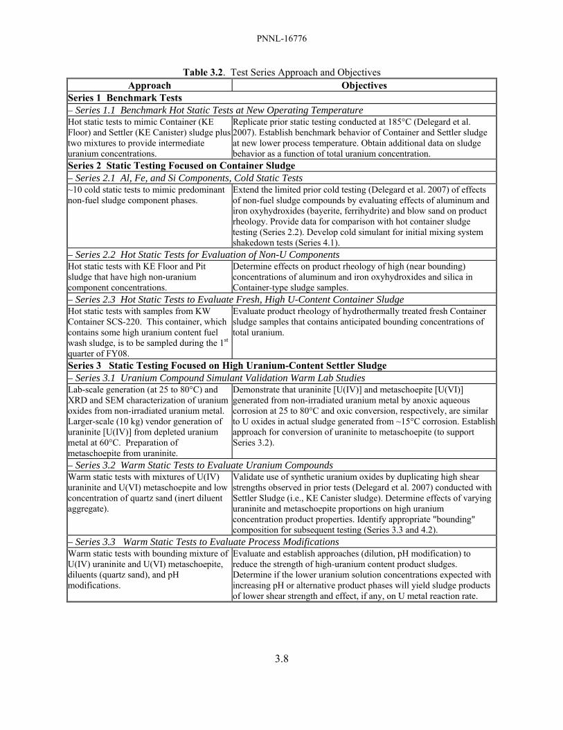
PNNL-16776
3.8
Table 3.2. Test Series Approach and Objectives Approach Objectives
Series 1 Benchmark Tests – Series 1.1 Benchmark Hot Static Tests at New Operating Temperature Hot static tests to mimic Container (KE Floor) and Settler (KE Canister) sludge plus two mixtures to provide intermediate uranium concentrations.
Replicate prior static testing conducted at 185°C (Delegard et al. 2007). Establish benchmark behavior of Container and Settler sludge at new lower process temperature. Obtain additional data on sludge behavior as a function of total uranium concentration.
Series 2 Static Testing Focused on Container Sludge – Series 2.1 Al, Fe, and Si Components, Cold Static Tests ~10 cold static tests to mimic predominant non-fuel sludge component phases.
Extend the limited prior cold testing (Delegard et al. 2007) of effects of non-fuel sludge compounds by evaluating effects of aluminum and iron oxyhydroxides (bayerite, ferrihydrite) and blow sand on product rheology. Provide data for comparison with hot container sludge testing (Series 2.2). Develop cold simulant for initial mixing system shakedown tests (Series 4.1).
– Series 2.2 Hot Static Tests for Evaluation of Non-U Components Hot static tests with KE Floor and Pit sludge that have high non-uranium component concentrations.
Determine effects on product rheology of high (near bounding) concentrations of aluminum and iron oxyhydroxides and silica in Container-type sludge samples.
– Series 2.3 Hot Static Tests to Evaluate Fresh, High U-Content Container Sludge Hot static tests with samples from KW Container SCS-220. This container, which contains some high uranium content fuel wash sludge, is to be sampled during the 1st quarter of FY08.
Evaluate product rheology of hydrothermally treated fresh Container sludge samples that contains anticipated bounding concentrations of total uranium.
Series 3 Static Testing Focused on High Uranium-Content Settler Sludge – Series 3.1 Uranium Compound Simulant Validation Warm Lab Studies Lab-scale generation (at 25 to 80°C) and XRD and SEM characterization of uranium oxides from non-irradiated uranium metal. Larger-scale (10 kg) vendor generation of uraninite [U(IV)] from depleted uranium metal at 60°C. Preparation of metaschoepite from uraninite.
Demonstrate that uraninite [U(IV)] and metaschoepite [U(VI)] generated from non-irradiated uranium metal by anoxic aqueous corrosion at 25 to 80°C and oxic conversion, respectively, are similar to U oxides in actual sludge generated from ~15°C corrosion. Establish approach for conversion of uraninite to metaschoepite (to support Series 3.2).
– Series 3.2 Warm Static Tests to Evaluate Uranium Compounds Warm static tests with mixtures of U(IV) uraninite and U(VI) metaschoepite and low concentration of quartz sand (inert diluent aggregate).
Validate use of synthetic uranium oxides by duplicating high shear strengths observed in prior tests (Delegard et al. 2007) conducted with Settler Sludge (i.e., KE Canister sludge). Determine effects of varying uraninite and metaschoepite proportions on high uranium concentration product properties. Identify appropriate "bounding" composition for subsequent testing (Series 3.3 and 4.2).
– Series 3.3 Warm Static Tests to Evaluate Process Modifications Warm static tests with bounding mixture of U(IV) uraninite and U(VI) metaschoepite, diluents (quartz sand), and pH modifications.
Evaluate and establish approaches (dilution, pH modification) to reduce the strength of high-uranium content product sludges. Determine if the lower uranium solution concentrations expected with increasing pH or alternative product phases will yield sludge products of lower shear strength and effect, if any, on U metal reaction rate.
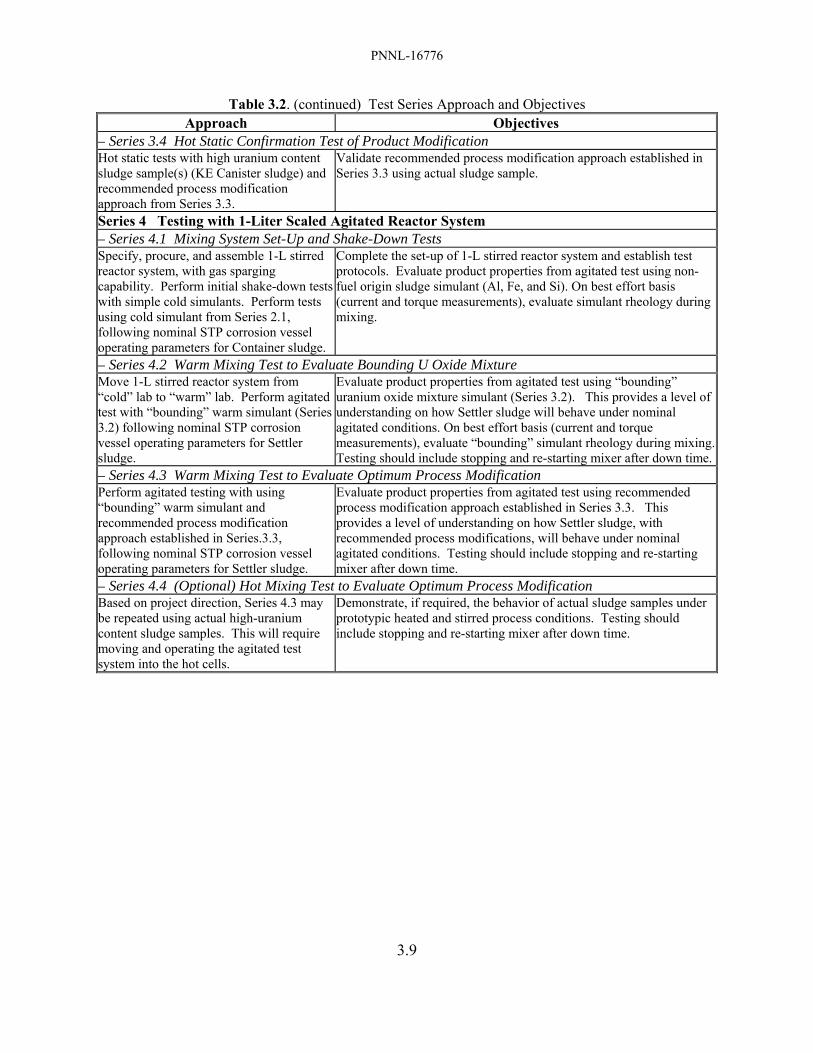
PNNL-16776
3.9
Table 3.2. (continued) Test Series Approach and Objectives Approach Objectives
– Series 3.4 Hot Static Confirmation Test of Product Modification Hot static tests with high uranium content sludge sample(s) (KE Canister sludge) and recommended process modification approach from Series 3.3.
Validate recommended process modification approach established in Series 3.3 using actual sludge sample.
Series 4 Testing with 1-Liter Scaled Agitated Reactor System – Series 4.1 Mixing System Set-Up and Shake-Down Tests Specify, procure, and assemble 1-L stirred reactor system, with gas sparging capability. Perform initial shake-down tests with simple cold simulants. Perform tests using cold simulant from Series 2.1, following nominal STP corrosion vessel operating parameters for Container sludge.
Complete the set-up of 1-L stirred reactor system and establish test protocols. Evaluate product properties from agitated test using non-fuel origin sludge simulant (Al, Fe, and Si). On best effort basis (current and torque measurements), evaluate simulant rheology during mixing.
– Series 4.2 Warm Mixing Test to Evaluate Bounding U Oxide Mixture Move 1-L stirred reactor system from “cold” lab to “warm” lab. Perform agitated test with “bounding” warm simulant (Series 3.2) following nominal STP corrosion vessel operating parameters for Settler sludge.
Evaluate product properties from agitated test using “bounding” uranium oxide mixture simulant (Series 3.2). This provides a level of understanding on how Settler sludge will behave under nominal agitated conditions. On best effort basis (current and torque measurements), evaluate “bounding” simulant rheology during mixing.Testing should include stopping and re-starting mixer after down time.
– Series 4.3 Warm Mixing Test to Evaluate Optimum Process Modification Perform agitated testing with using “bounding” warm simulant and recommended process modification approach established in Series.3.3, following nominal STP corrosion vessel operating parameters for Settler sludge.
Evaluate product properties from agitated test using recommended process modification approach established in Series 3.3. This provides a level of understanding on how Settler sludge, with recommended process modifications, will behave under nominal agitated conditions. Testing should include stopping and re-starting mixer after down time.
– Series 4.4 (Optional) Hot Mixing Test to Evaluate Optimum Process Modification Based on project direction, Series 4.3 may be repeated using actual high-uranium content sludge samples. This will require moving and operating the agitated test system into the hot cells.
Demonstrate, if required, the behavior of actual sludge samples under prototypic heated and stirred process conditions. Testing should include stopping and re-starting mixer after down time.

PNNL-16776
3.10
Table 3.3. Test Materials and Conditions Composition, wt% as Element, Dry Basis (a)
Test ID Description/Objective Sludge Material U(IV) U(VI) U(0) Al Fe Si
Temp (°C) / Time (hr)
1.1 Benchmark Hot Static Tests at New Operating Temperature (Mimic Container and Settler Sludge plus two intermediate U concentrations) 1 Mimic Container Sludge KC-4 16.6, total U 6.8 24.3 4.9 150/171 2 Intermediate U concentration KC-4 & KC-2/3 30.7, total U 6.1 16.8 3.5 150/171 3 Intermediate U concentration KC-4 & KC-2/3 44.9, total U 5.7 9.3 2.2 150/171 4 Mimic Settler Sludge KC-2/3 59.0, total U 5.2 1.8 0.8 150/16
2.1 Al, Fe, and Si Components, Cold Static Tests (Effects of aluminum and iron oxyhydroxides and blow sand on product rheology)
TBD Series (~10) cold tests to evaluate effects of aluminum and iron oxyhydroxides (bayerite, ferrihydrite) and blow sand on product rheology.
Non-rad simulants 0 0 0 3 - 16 8 - 42 0 - 36 150/171
2.2 Hot Static Tests for Evaluation of Non-U Components (Effects of high Al and Fe oxyhydroxides and silica concentrations on product rheology) 1 High aluminum KE Floor Sludge KC Floor Comp 11.9, total U 15.8 23.2 6.6 150/171 2 High iron KE Weasel Pit Sludge FE-5 4.1, total U 2.7 30.6 0.3 150/171 3 High silicon KE NLOP sludge KE NLOP 2.5, total U 3.9 6.8 36.3 150/171
2.3 Hot Static Tests to Evaluate Fresh, High U-Content Container Sludge (SCS-220 will be sampled in FY08 – contains some fuel wash sludge)
1-3 Several static (and optional mixed) tests to confirm processability of fresh, high U-content container sludge.
SCS CON 220 TBD; likely ~30 wt% U, dry basis 150/171
3.1 Uranium Compound Simulant Validation Warm Lab Studies (Generation and characterization of uranium oxides from depleted uranium metal)
NA
Generate uraninite [U(IV)] and metaschoepite [U(VI)] from depleted uranium (DU) metal. Demonstrate (XRD, SEM) that products are similar to U oxides in actual sludge.
Depleted U metal to make uraninite and metaschoepite
0-88 74-0 0 0 0 0 NA
3.2 Warm Static Tests to Evaluate Uranium Compounds (Evaluate effects of uraninite and metaschoepite on product properties) 1 Uraninite 79 0 0 0 0 5 150/16 2 Uraninite/metasch. 53 22 0 0 0 5 150/16 3 Uraninite/metasch. 40 33 0 0 0 5 150/16 4 Uraninite/metasch. 27 44 0 0 0 5 150/16 5
Determine effects of varying uraninite and metaschoepite proportions on high uranium concentration product properties. Quartz sand serves as non-reactive diluent. Identify appropriate "bounding" composition for subsequent testing. Metaschoepite 0 66 0 0 0 5 150/16

PNNL-16776
3.11
Table 3.3. (continued) Test Materials and Conditions 3.3 Warm Static Tests to Evaluate Process Modifications (Effects of dilution, pH control, and additives on product properties)
1 Uraninite/metasch. 35 30 0 0 0 9 150/16 2 Uraninite/metasch. 26 22 0 0 0 19 150/16 3 Uraninite/metasch. 18 15 0 0 0 28 150/16 4
Determine effects of dilution with quartz sand on product properties for high uranium concentration mixtures. U(IV):U(VI) ratios will be based on Series 3.2 Testing. Uraninite/metasch. 9 7 0 0 0 37 150/16
5 Uraninite/metasch. 40 33 0 0 0 5 150/16 6 Uraninite/metasch. 40 33 0 0 0 5 150/16 7 Uraninite/metasch. 40 33 0 0 0 5 150/16 8 Uraninite/metasch. 40 33 0 0 0 5 150/16 9
Determine whether sludge agglomeration can be reduced by pH/mineral additives [Fe(0), CaCO3, Ca(OH)2, phosphate] to limit U(VI) solubility. Confirm that U oxidation rate not affected.
Uraninite/metasch. 37 31 5 0 0 5 150/16-171 3.4 Hot Static Confirmation Test of Product Modification (Static hot testing of optimized processing of sludge as determined from Series 3.3)
1 Evaluate behavior of genuine sludge under optimum processing conditions as determined by Series 3.3 testing.
Composition determined by results of Series 3.3 testing 150/16-171
4.1 Mixing System Set-up and Shake-Down Tests (Cold testing to prepare mixing test apparatus and evaluate cold simulant from Series 2.1) 4.2 Warm Mixing Test to Evaluate Bounding U Oxide Mixture (Testing in mixing apparatus to evaluate “bounding” warm simulant from Series 3.2)
1
Evaluate behavior of U oxide mixture under nominal mixing, evaporation, and solids loading conditions (composition may vary from that given depending on Series 3.2 test outcomes).
Uraninite/metasch. 40 33 0 0 0 5 150/16
4.3 Warm Mixing Test to Evaluate Optimum Process Modification (Warm mixing test of optimized sludge processing as determined from Series 3.3)
1 Evaluate behavior of warm simulant sludge under optimum processing conditions as determined by Series 3.3 testing.
Composition determined by results of Series 3.3 Testing 150/16-171
4.4 Optional Hot Mixing Test to Evaluate Optimum Process Modification (Hot mixing test of optimized sludge processing as det’d. from Series 3.3)
1 Evaluate behavior of genuine sludge under optimum processing conditions as determined by Series 3.3 testing.
Composition determined by results of Series 3.3 Testing 150/16-171
(a) Sludge compositions are given in dry weight basis to allow better cross comparison. However, simulant sludge compositions on as-settled or other wet bases will be determined and compared with compositions of genuine sludge to establish that bulk density and water concentration are similar.

PNNL-16776
3.12
The “cold” tests to investigate the roles of non-radioactive sludge components [including, at minimum, bayerite, Al(OH)3, for aluminum; goethite and lepidocrocite, both FeOOH, and amorphous ferric hydroxide, Fe(OH)3, for iron; and quartz, SiO2, and amorphous hydrated silica, SiO2·xH2O, for silicon] on product properties are more limited than originally envisioned. In the initial plans, these components would first have to be characterized more fully in K Basins sludge. Non-radioactive components then would have to be obtained commercially or synthesized and demonstrated to suitably mimic the chemical and physical properties of their sludge counterparts. To identify the roles of the individual components and their interactions, multi-factorial experimental testing then would be required. The results of the testing still would have needed to be verified by comparison testing with actual K Basin sludge. Instead of using surrogates to determine the roles of sludge components on product qualities such as vessel wall adhesion, shear strength, and water content, “hot” tests will be performed with K Basin sludge samples having a variety of key elemental (aluminum, iron, silicon, and uranium) concentrations. More limited “cold” tests will be performed solely to identify suitable surrogate sludge compositions for engineering-scale testing while “warm” tests will focus on the special role of uranium components (uraninite and metaschoepite) on product sludge properties. Broad descriptions of each test series or single test are provided in the following narrative with further detail provided in ensuing sections of this Test Plan. 3.1 Test Series 1.1, 2.2, 2.3, and 3.4: Small Scale Static Hot Tests The Test Series 1.1 and 2.2 experiments are designed to examine the behaviors of K Basin sludge compositions based on the expected range of Container/Settler sludge blends and Container sludge, respectively. The benchmark Test Series 1.1 will focus on the effects of uranium concentration and the revised 150°C process temperature on the properties of the sludge product. Test Series 2.1 will examine the effects of the other three principal sludge constituents, aluminum, iron, and silicon, and the 150°C process temperature on the sludge product properties. The products in both test series will be measured for water and gas retention, pH phase changes, shear strength, and vessel wall adhesion after nominal STP process treatment. For these test series, samples of sludge having compositions similar to the nominal Container sludge and Settler sludge and samples relatively rich in aluminum, iron, and silicon will be used. Test Series 2.3 will be performed with a sample of the KW Basin Container sludge that is scheduled to be retrieved for analysis early in FY2008. To perform this test, sufficient sample of the KW container (SCS-CON-220) would have to be retrieved to satisfy both the original characterization goals (Makenas 2007) and the supplementary STP process testing. Test Series 3.4 is a confirmatory test. The objective is to verify that methods such as dilution with inert material (by quartz sand, for example) to decrease uranium concentration), chemical or pH amendments [using CaCO3, Ca(OH)2, and mixed sodium phosphate salts], and possibly lower temperature processing are successful to avoid high strength products in actual sludge. These approaches will be developed under Test Series 3.2 and 3.3 by warm testing. Because lower (150°C) processing temperatures will be used, the sludges will be reacted without a stepped temperature increase program as was done in prior testing at 185°C. The temperature hold for these tests of Container sludge and sludge blends at 150°C will be 171 hours. The test vessels then will be opened and the products evaluated for water separation, pH gas retention, shear strength (using a soil penetrometer), and phase changes (by X-ray diffraction, XRD, and scanning electron microscopy, SEM).
PNNL-16776
3.13
The compositions of candidate Settler and Container sludges to cover the range of compositions for Test Series 1.1 and 2.3 are described in Section 7.0. These sludge materials also would be used in Test Series 3.5. The tests will be conducted in 128-ml Parr Model 4754 pressure vessels (see Section 4.0). If penetrometer testing of the static (no agitation) products of Container and Settler “hot” sludge materials indicates relatively low shear strengths, “hot” testing with stirring and evaporation would be unnecessary. 3.2 Test Series 2.1: Evaluate Al, Fe, and Si Phase Sludge Components “Cold” simulants will be required for shake-down testing of the lab-scale (1-liter) stirred reactor system and perhaps also for prototype process equipment. Investigations of the properties of the products of hydrothermal treatment of non-radioactive sludge also are valuable to help understand the results of “hot” testing of sludges rich in non-uranium phases conducted under Test Series 2.2. The objective of the static “cold” simulant formulation Test Series 2.1 is to obtain information on hydrothermal products having rheological properties similar to K Basin sludge. Prior testing showed that a simulant sludge containing aluminum [as gibbsite, Al(OH)3], iron [as ferrihydrite, Fe5O7(OH)·4H2O], and silicon (as blow sand, primarily quartz, SiO2, and basalt), blended with water and the dispersed Nalco flocculating agent, and reacted at nominal 185°C STP process conditions for Container sludge, produced a product with high shear strength (Delegard et al. 2007). The effects on product sludge strength of varying ratios of these three components will be determined in a series of about 10 tests. Further information on the test matrix design is given in Section 7.5. 3.3 Test Series 3.1: Production and Validation of Synthetic Uraninite and
Metaschoepite from Depleted Uranium The initial STP process testing showed that high strength products arose by processing of Settler-type sludges having high uranium concentrations. The principal uranium phases identified in the sludge feeds used in the prior testing were uraninite, UO2.x, and metaschoepite, UO3·2H2O, as well as uranium metal. Test Series 3.1 is designed to produce synthetic UO2.x and UO3·2H2O from un-irradiated depleted uranium metal. Production of these phases allows parametric experimentation on the effects of sludge composition to be performed under Test Series 3.2 and 3.3 and mixed reactor testing under Test Series 4.2 and 4.3 and reserves archived K Basin sludge samples for validation testing under Test Series 2.2 and 3.5. The UO2.x is being produced by a commercial vendor by corroding uranium metal shavings in water. The UO3·2H2O will be produced in the PNNL laboratories by air oxidation of UO2.x. The uraninite and metaschoepite phase properties will be compared with their properties as encountered in K Basin sludge by use of X-ray diffractometry and scanning electron microscopy techniques. Further descriptions of the preparation and characterization of the uraninite and metaschoepite phases are given in Section 7.3. 3.4 Test Series 3.2 and 3.3: Small Scale Warm Static Tests with Depleted Uranium Test Series 3.2 and 3.3 are designed to examine the effects of sludge composition (particularly for two uranium phases, uraninite and metaschoepite), dilution, pH, and possibly temperature on sludge product shear strength and vessel wall adhesion. The tests in this Series will be conducted in the same small-scale pressure vessels as used in the small scale hot static testing (see Section 3.1) under STP process

PNNL-16776
3.14
conditions appropriate for Settler sludge (temperature ramp to 150°C followed by a 16-hour hold and subsequent cool-down) or Container sludge (ramp to 150°C followed by 171-hour hold and cool-down). Based on the prior testing (Delegard et al. 2007), the products of the STP process tests with the uraninite and metaschoepite, formulated to produce sludge compositions imitating those of Settler sludge, are expected to have high shear strength as measured by soil penetrometer. The effects of diluting the uranium phases with silica (quartz) sand, use of additives (including pH amendments), and possibly process temperature decrease on product strength will be investigated by small-scale testing. The simulated sludge will be made using the uraninite prepared by corroding depleted uranium metal and the metaschoepite prepared by reaction of uraninite with oxygen. The results from these tests will provide supplemental information on potential avenues to decrease STP product sludge shear strength. The Settler sludge in the prior two tests ranged between pH ~4 and 5, both before and after hydrothermal treatment. As shown in Figure 3.6, the solubility of metaschoepite decreases steeply as pH is raised from pH 4 to 5 to pH 6 to 8. If lower metaschoepite solubility is imposed by pH adjustment to the range 6 to 8, solid phase alteration reactions may be inhibited and the post-treatment strength, thought to be due to self-cementation, lowered.
-6.0
-5.5
-5.0
-4.5
-4.0
-3.5
-3.0
-2.5
-2.0
-1.5
-1.0
3 4 5 6 7 8 9 10 11 12
pH
log[
U],
M
Figure 3.6. Solubility of Metaschoepite, UO3·2H2O, at 25°C (Shoesmith 2000)
From process simplicity, it is desirable that the pH be adjusted using buffered solid materials that can be added directly to the sludge streams. Three pH-adjusting materials, calcium carbonate (calcite; CaCO3), calcium hydroxide [slaked lime; Ca(OH)2], and sodium hydrogen phosphate (an equimolar mixture of Na2HPO4 and NaH2PO4), are suggested for testing. The CaCO3 and Ca(OH)2 will have the effect of converting metaschoepite to the calcium uranyl oxyhydroxide mineral, becquerelite [Ca(UO2)6O4(OH)6(H2O)8], or, in the presence of sufficient dissolved silica, the calcium uranyl silicate oxyhydroxide, uranophane [Ca(UO2)2(SiO3OH)2(H2O)5], instead of the soddyite [(UO2)2SiO4(H2O)2] found in the prior Tests 1 and 2 using the Settler sludge. (Chemical) activity-activity diagrams in Figures 3.7 and 3.8 show the uranyl phase stability fields and, respectively, how the calcium carbonate and calcium (hydroxide) plus silica can convert metaschoepite to becquerelite and uranophane.

PNNL-16776
3.15
-4.0
-3.5
-3.0
-2.5
-2.0
-1.5
-1.0
-0.5
0.0
2 3 4 5 6 7 8 9 10 11 12 13 14 15 16
log [a (Ca2+)/a (H+)2]
log
[fC
O2]
RutherfordineUO2CO3
FontaniteCa(UO2)3(CO3)4(H2O)3
UrancalcariteCa2(UO2)3(CO3)(OH)6(H2O)3
SharpiteCa(UO2)6(CO3)5(OH)4(H2O)6
Calcite (CaCO3) equilibrium
BecquereliteCa(UO2)6O4(OH)6(H2O)8
MetaschoepiteUO3·2H2O
Figure 3.7. Activity-Activity Diagram for the System CO2-CaO-UO3-H2O
(after Finch and Murakami 1999)
-6.0
-5.5
-5.0
-4.5
-4.0
-3.5
-3.0
-2.5
-2.0
2 3 4 5 6 7 8 9 10 11 12 13 14 15 16
log [a (Ca2+)/a (H+)2]
log
[a(S
iO2
(aq)
)]
MetaschoepiteUO3·2H2O
Soddyite(UO2)2SiO4(H2O)2
HaiweeiteCa(UO2)2[Si5O12(OH)2](H2O)4.5
UranophaneCa(UO2)2(SiO3OH)2(H2O)5
SwamboiteU(UO2)6(SiO3OH)6(H2O)30
BecquereliteCa(UO2)6O4(OH)6(H2O)8
Figure 3.8. Activity-Activity Diagram for the System SiO2-CaO-UO3-H2O
(after Finch and Murakami 1999) In Figure 3.7, the effect of adding excess calcite (CaCO3) to metaschoepite can be seen by following the equilibrium line for calcite. It is seen that most of this equilibrium line lies within the region defined for becquerelite stability. Only with high carbon dioxide (CO2) fugacities (>10-0.65 ≅ 0.22 atmospheres) are phases other than becquerelite formed, i.e., rutherfordine or perhaps sharpite. Such high CO2 pressures are not possible in the nitrogen-sparged STP process reactor. The quantity of CaCO3 necessary to convert

PNNL-16776
3.16
metaschoepite completely to becquerelite is set by the reaction stoichiometry of Ca:6U (mole ratio) or about 1 gram of CaCO3 per 48 grams of metaschoepite:
CaCO3 + 6 UO3·2H2O → Ca(UO2)6O4(OH)6(H2O)8 + H2O + CO2 As shown by interpretation of the mineral stability fields in Figure 3.8, slaked lime, Ca(OH)2, could be added to the sludge with perhaps some active source of silica (e.g., blow sand containing basalt having active silica in a glassy matrix) if silica concentrations are too low in the sludge itself to convert the metaschoepite to uranophane. The activity of dissolved silica (SiO2 (aq)) in waters in equilibrium with most soils is about 10-3 molal. At 10-3 molal SiO2 (aq) and pH 8 (10-8 molal H+), easily reached with addition of slaked lime, calcium activities greater than about 10-9 molal will thermodynamically favor production of uranophane. The quantities of silica and slaked lime necessary to convert metaschoepite completely to uranophane are dictated by the reaction stoichiometry of 2Si:Ca:2U or about 1.6 grams of SiO2 and 1 gram of Ca(OH)2 per 8.7 grams of metaschoepite.
2 SiO2 + Ca(OH)2 + 2 UO3·2H2O → Ca(UO2)2(SiO3OH)2(H2O)5 Examination of Figure 3.8 also shows that in the presence of silica but without sufficient calcium, metaschoepite will convert to soddyite, (UO2)2SiO4(H2O)2. The conversion of metaschoepite to soddyite (and to dehydrated schoepite) was observed in the prior Settler sludge hydrothermal testing for sludge KC-2/3 M250 (Delegard et al. 2007). This sludge has a mole ratio of 4.3Si:Ca:120U versus the Si:2U mole ratio needed for complete conversion of metaschoepite to soddyite and the 2Si:Ca:2U mole ratio needed for complete conversion to uranophane. Consideration of these ratios thus helps explain the observation of low quantities of soddyite in the hydrothermal product but the absence of uranophane. The solubility of sodium autunite {(Na2,Ca)[(UO2)(PO4)]2(H2O)8}, about 2.5×10⁻⁷ molar at pH 4.5-8.5 (Zheng et al. 2006), is lower than that of metaschoepite. The conversion of metaschoepite to sodium autunite can occur by the addition of sodium phosphate salts to the metaschoepite-bearing sludge and by providing, as required, a sufficient source of calcium. The pure (calcium-free) sodium autunite product has a mole ratio of 2Na:2PO4:2U and proceeds according to the following reaction.
NaH2PO4 + Na2HPO4 + 2 UO3·2H2O + 5 H2O → Na2[(UO2)(PO4)]2(H2O)8 + NaOH To allow slower equilibration and possibly limit the early reaction of phosphate with calcium in the sludge (to form brushite, CaHPO4), the phosphate may be introduced in the form of sodium polyphosphate (e.g., pentasodium triphosphate, Na5P3O10). This salt hydrolyses slowly to release phosphate which then may react with the uranium as the hydrolysis proceeds (Wellman et al. 2006). Test Series 3.2 will investigate the relative roles of uraninite and metaschoepite (and perhaps temperature) on sludge strength and other product properties. The “bounding” composition (i.e., that composition yielding the strongest sludge product) then will be used in Test Series 3.3. In Test Series 3.3, the warm testing will be expanded to investigate the roles of dilution and pH and chemical amendments on product properties. The testing also will confirm the expectation that the uranium metal – water reaction rate is not affected by the dilution or particularly the chemical/pH amendments. The outcomes of these test series will be used to guide confirmatory hot testing with K Basin sludge under static hot Test Series 3.4.

PNNL-16776
3.17
3.5 Test Series 4.1: Bench-Scale Cold Tests with Agitation and Evaporation The primary objective of Test Series 4.1 is to examine the effects of agitation and potentially evaporation on the strengths of STP process products produced from non-radioactive (cold) K Basin sludge simulant materials. The tests also will serve to further shake-down the apparatus and vessels which also will be used in warm validation Test Series 4.2 (with the “bounding” high shear uranium-bearing sludge) and 4.3 (with the “bounding” sludge tested under optimized process conditions as developed under Test Series 3.2 and 3.3). The test vessel(s) to be used in Test Series 4.1 (and the successor Test Series 4.2 and 4.3) are being designed. Initial design considerations indicate that meaningful information on the performance of the process reactor vessel may be obtained by judicious selection of agitation level (stirring rate) of ~800 RPM in a smaller, ~1-liter, test apparatus. Features internal to the small- to bench-scale reaction vessel also include vessel shape, internal baffling (to prevent vortexing), and impeller design. The resistance to mixing afforded by the simulated sludge is of process interest. Additional validation of the test approach is planned under this Test Series activity. Preliminary vessel design and agitation considerations, including the outcomes of initial hydraulic calculations, are presented in Appendix A. In addition to vessel and agitation design features, elaborate gas sparging, pressure let-down, and condensate collection apparatus must be prepared for these tests if sparging and water evaporation operations are to be included. Suitable commercially-available test equipment likely exists although custom vessel construction probably is required. The equipment must be specified, purchased, assembled, and tested before experiments with the cold sludge simulants are undertaken. Because of these necessary preliminary actions, the scope of activities under this Test Series have not been completely defined at the time of preparation of this Test Plan. Test Series 4.1 is being conducted to examine the behavior of “cold” simulated sludge under agitation and gas sparging / water evaporation STP conditions. The simulated sludge composition will be derived during activities under Test Series 2.1. These tests with non-radioactive simulated sludge can be conducted in non-radiological PNNL laboratory facilities but also may be performed in the RPL. The sludge mechanical properties to be examined will include the ability to discharge the product from the vessel (by strength measurements), hot wall deposition, solids precipitation, dry-out and foaming, and potentially agitator resistance (as measured by motor current or torque) to monitor sludge rheology on-line. The sludge product also will be characterized by pH and XRD and SEM examination. The test results will provide further information on the prospective behavior of sludge under STP process conditions. 3.6 Test Series 4.2, 4.3, and (optional) 4.4: Bench-Scale Tests with Agitation and
Evaporation Test Series 4.2 and 4.3 are being performed to provide information on the behavior of the “warm” K Basin sludge formulation bounding for high strength under both original (Test Series 4.2; bounding) and “optimized” (formulated with pH / chemical amendments) under STP process conditions involving agitation and evaporation. The agitation and evaporation testing performed under the predecessor Test Series 4.1 will provide the information needed in selecting and proof-testing the laboratory apparatus. Because the testing under Test Series 4.2 and 4.3 will involve “warm” simulated sludge samples, the experimentation will occur in RPL fume hood facilities.
PNNL-16776
3.18
Based on project direction, Test Series 4.4 may be performed using actual high-uranium content sludge samples. This Test Series duplicates the process conditions selected for Test Series 4.3 including agitation. This will require adapting the agitated test system for operation in the hot cells. The objective is to demonstrate the behavior of actual sludge samples under prototypic heated and stirred process conditions. 3.7 Sludges Containing High Concentrations of Uranium Metal (KOP Sludge) In the previous testing (Delegard et al. 2007), high uranium metal content sludges were not investigated. The overall volume of KOP sludge to be processed by the STP is low (~0.26 m3) and the KOP sludge will be processed at low solids content (0.9 to 3.2 volume percent solids, assuming homogeneous mixing) within the corrosion vessel. Furthermore, in prior hydrothermal testing with uranium metal-rich sludge at temperatures up to 95°C, the resulting uranium oxide products were predominantly uraninite and were readily suspendable (Schmidt et al. 2003). Therefore, the current testing does not include a series that is directly focused on the behavior of KOP sludge under process conditions since it is not judged to be a limiting activity within the STP processing. However, indirect information on the behavior of KOP sludge processing will be provided within Test Series 3.2 and 3.3 which include testing to examine the behavior of uraninite at the STP operating temperatures. The KOPs are also expected to contain graphite (from disintegrated KW Grafoil canister seals), but at STP temperature, graphite is not expected to react or interact with other sludge constituents.
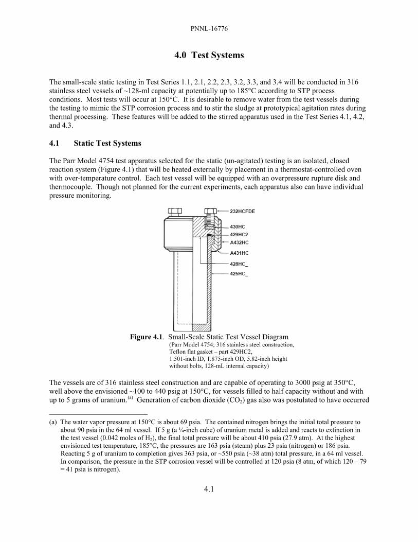
PNNL-16776
4.1
4.0 Test Systems The small-scale static testing in Test Series 1.1, 2.1, 2.2, 2.3, 3.2, 3.3, and 3.4 will be conducted in 316 stainless steel vessels of ~128-ml capacity at potentially up to 185°C according to STP process conditions. Most tests will occur at 150°C. It is desirable to remove water from the test vessels during the testing to mimic the STP corrosion process and to stir the sludge at prototypical agitation rates during thermal processing. These features will be added to the stirred apparatus used in the Test Series 4.1, 4.2, and 4.3. 4.1 Static Test Systems The Parr Model 4754 test apparatus selected for the static (un-agitated) testing is an isolated, closed reaction system (Figure 4.1) that will be heated externally by placement in a thermostat-controlled oven with over-temperature control. Each test vessel will be equipped with an overpressure rupture disk and thermocouple. Though not planned for the current experiments, each apparatus also can have individual pressure monitoring.
Figure 4.1. Small-Scale Static Test Vessel Diagram
(Parr Model 4754; 316 stainless steel construction, Teflon flat gasket – part 429HC2, 1.501-inch ID, 1.875-inch OD, 5.82-inch height without bolts, 128-mL internal capacity)
The vessels are of 316 stainless steel construction and are capable of operating to 3000 psig at 350°C, well above the envisioned ~100 to 440 psig at 150°C, for vessels filled to half capacity without and with up to 5 grams of uranium.(a) Generation of carbon dioxide (CO2) gas also was postulated to have occurred
(a) The water vapor pressure at 150°C is about 69 psia. The contained nitrogen brings the initial total pressure to
about 90 psia in the 64 ml vessel. If 5 g (a ¼-inch cube) of uranium metal is added and reacts to extinction in the test vessel (0.042 moles of H2), the final total pressure will be about 410 psia (27.9 atm). At the highest envisioned test temperature, 185°C, the pressures are 163 psia (steam) plus 23 psia (nitrogen) or 186 psia. Reacting 5 g of uranium to completion gives 363 psia, or ~550 psia (~38 atm) total pressure, in a 64 ml vessel. In comparison, the pressure in the STP corrosion vessel will be controlled at 120 psia (8 atm, of which 120 – 79 = 41 psia is nitrogen).

PNNL-16776
4.2
by sludge reactions in the previous hydrothermal testing based on prior gas generation experiments (Delegard et al. 2007). To allow for gas generation and for expansion of the solid and water phases, the maximum planned sample volume in each 128 ml Parr vessel is 66% of 128 ml, or 85 ml, without added uranium metal or 64 ml with uranium metal. Each vessel will have a ¼-inch tee fitting to accept a thermocouple and an overpressure rupture disk selected, at ~3000 psi per Parr recommendation, to provide adequate safety margin without risk of rupture disk failure during normal operations. According to the vendor, the bolts are tightened using a crisscross pattern, applying a firm but hard pull to reach ~25 ft-lbs applied torque. The vessel stands for about five minutes after the initial tightening and is tightened again to ~25 ft-lbs to compensate for any PTFE (polytetrafluoroethylene) gasket flow under the bolt loading.(a) The tests will be performed under 100% nitrogen (N2) cover as is true for the full scale STP hydrothermal processing of the K Basin sludge. The temperatures in each reaction vessel will be followed by a calibrated thermocouple placed in the sludge materials. The temperature will be recorded over the test duration using data logging equipment. At the conclusion of the reaction test period, the external oven heating to the reactors will be shut off, the reactors allowed to cool to ambient temperature, and the lids opened to allow any pressurized gases (e.g., carbon dioxide, hydrogen) within the reaction system to escape. The rates of gas generation (e.g., gas pressure) and the gas composition (e.g., sampling for mass spectrometric analysis) will not be measured for tests with this apparatus although subsequent modifications can be made to permit this. 4.2 Stirred Test Systems Water removal and prototypical agitation rates during thermal process testing are desired to mimic the STP corrosion process. These features will be added to the apparatus used in the Test Series 4.1, 4.2, and 4.3. Diagrams of a stirred 1-liter vessel with 4-inch internal diameter, shown in Figure 4.2, illustrate a candidate vessel layout (see also Appendix A). Further features on the stirred vessel system design, including heating system (likely a mantle with feedback temperature control) and a gas sparging system, pressure let-down, condensate collection, and stirrer resistance measurement, are being refined. Implementing water evaporation and stirring to the testing adds substantial complexity and time to the test program but are possible using experience in pressurized reactor design available at Parr and PNNL. The stirring design is significant and must take into account the full-scale process vessel geometry (height, diameter, presence and placement of baffles) with the test vessel(s)’ stirrer speed and torque measured to provide useful sludge mixing data. The stirred reactor with water evaporation control (requiring pressure let-down and condensate collection) will be designed and tested concurrently with the performance of the static (non-stirred) experimental program under the static Test Series (e.g., 1.1, 2.1). Based on the expert panel review (Abrefah et al. 2007) useful data will be provided from testing the currently planned reactor system [~1 liter (at 4-inch internal diameter) with ~800 RPM stir rates (see Appendix A)].
(a) See pages 8 and 25 of “Operating Instruction Manual 4600 & 4700 General Purpose Pressure Vessels,” Parr
Instrument Company, Moline, IL (http://www.parrinst.com/doc_library/members/239M.pdf).

PNNL-16776
4.3
M
NitrogenInlet
Back PressureRegulator(Low Flow)Mass Flow
Controller(Low Flow)
Knockout Pot
DoubleBall Valves1000 mL
Parr Vessel
Figure 4.2. Stirred Test Vessel Diagrams Based on Parr Model 4523 with O-Ring Gasket.
Upper left: Perspective Upper right: Vessel cross-section Bottom: System schematic.

PNNL-16776
5.1
5.0 Test Approach Summary The static tests under Test Series 1.1, 2.1, 2.2, 2.3, 3.2, 3.3, and 3.4 will utilize the following operational sequence:
• Label vessels • Load the vessels with targeted amounts of sludge, water, OIER, flocculent, and uranium fuel (as
directed in the test matrix) • Collect video records of the contents during loading • Weigh the loaded vessel • Close reaction vessel • Heat to nominal processing temperature (typically 150°C); no intermediate dwell is required • After selected ~16-171 h heating, turn off oven power, cool to ambient temperature, and open • Record video images of material and remove test material contents • Conduct post-test evaluations.
After completion of the heating and cooling cycle, the following post-test evaluations will be performed (further details on post-test analyses are provided in Section 8.0):
• Weigh the vessel
• Open the vessel
• Collect video records of contents after opening and during removal into jars
• Decant supernatant liquid into jar for potential analyses and weigh
• Measure supernatant liquid pH
• Probe solids for self-cementation using penetrometer
• If stirring tests are to be performed, take solids sample using cut-off 10-ml syringe
• Perform stirring tests as required
• Remove solids into another jar
• Examine solids for evidence of unreacted U metal and condition of OIER, if present
• Collect video images of vessel wall for evidence of adhesion and foaming
• Probe vessel wall for adhering particles
• Collect representative solids sample for analyses (e.g., X-ray diffractometry for crystalline phase analysis; SEM/EDS, energy dispersive spectrometry, for particle size, particle shape, and elemental distribution)
• Optional – sieve remaining solids and weigh sieved portions to determine granularity and sample sieved fractions for analyses.
The K Basin sludge samples will continue to be handled per requirements of the most recent Sampling Analysis Plan (SAP, Baker et al. 2000).
PNNL-16776
5.2
The operational sequences for the agitated Test Series 4.1, 4.2, and 4.3 will include most of the same operations listed above for the static Test Series (e.g., 1.1 and 2.1). Additional operating parameters will include impellor location, rotational speed, operating pressure and nitrogen sparge rate. Initial observations on sludge rheology will be made immediately after discharging the slurry or soon after the mixing is stopped and the vessel is opened. Thus, the time between run completion and rheological observations will be minimized.

PNNL-16776
6.1
6.0 Basis for Test Matrix/Test Parameters Test parameters are designed to emulate those of the K Basin feed sludge and the STP process. Information on test temperatures and temperature profiles, test volumes, sludge/water ratios, and flocculating agent are described in the following sections. Because the objective of the testing is to identify gross effects of process variation, duplicate tests are not performed. The test matrices are generally broad, allowing discernment of trends in measured outcomes as functions of process variation. 6.1 Test Temperature and Time The objective of this testing is to evaluate the behavior of selected K Basin sludges with the STP corrosion process consistent with Section 2.0. The STP parameters for the corrosion process, provided in Table 6.1, are based on the evaluations of Woodworth (2006) and subsequent considerations arising from the 150°C processing temperature guidance (note that process conditions have not yet been specified by the process engineering).
Table 6.1. Operating Parameter for the STP Corrosion Process Sludge Solids Concentration,
Volume Percent Solids Sludge Type/ Parameter
Corrosion Temp., °C
(a)
Heat-up Time, h
(a)
Corrosion Hold Time, h
(a)
Cooling Time, h
(a) Initial Final Container Sludge 150 6 171 12.7 10.1 20 (b)
Settler Sludge 150 6 16 2.1 5.9 9.0 KOP Sludge 150 6 171 4.7 0.90 3.2 (a) Process conditions have not yet been specified by process engineering. (b) Settled Container sludge is nominally 25 vol% solids as it exists as-settled at K Basin.
To the extent achievable, the testing will match the STP process parameters for temperature and times. The temperature of the contents of each vessel will be monitored and recorded during the entire test cycle. Heat-Up and Hold Time: The temperature of the oven will be stepped up manually to attain the target vessel temperature of 150°C within six hours. Figure 6.1 shows the planned experimental heating profile for STP processing of K Basin Container sludge in a 30°C hot cell. Unlike the tests at 185°C, there will be no intermediate 12-hour dwell at 140°C. The intermediate hold temperature should have been 160°C, according to process engineering goals. Because the revised 150°C processing temperature lies below the prior 160°C hold temperature, no need exists for the lower temperature hold. The ambient temperature of the non-radioactive “cold” tests and depleted uranium “warm” tests will be that of the fume hood, ~21°C. The temperature profile for Settler sludge is similar to that of Container sludge but the dwell time at 150°C is 16 hours (to corrode a 600-μm particle). Tests having blends of Settler and Container sludge will be processed at the longer (171 hour) residence time to reflect the 150°C thermal processing necessary to ensure the complete reaction of a nominal ¼-inch uranium metal particle present in Container sludge. Cool Down: Tests will cool down by turning the oven power off and leaving the vessels in the oven. No attempt will be made to actively control the vessel temperatures during cooling.

PNNL-16776
6.2
20
40
60
80
100
120
140
160
0 50 100 150 200Time, hours
Tem
pera
ture
, °C
171-Hour Dwell at 150°C
Begin and End at AmbientHot Cell Temperature ~30°C
Oven Shut Off and Vessels Cooled
within Oven
Figure 6.1. Target Vessel Temperature Profile for Processing Container Sludge
6.2 Basis for Test Size and Sludge/Water Concentration Nominal Container sludge is 25% solids by volume (settled basis); corroded Settler and KOP sludges are estimated to be ~35 vol% solids (after uranium metal oxidation). For the testing to achieve a 20 vol% solids loading for 62.5 ml total volume (static test apparatus), each test will be conducted with 50 ml of settled sludge and 12.5 ml of additional free water (62.5 ml × 20 vol%/25 vol%). For Container sludge, this loading matches the end-of-batch solids content, or 20 vol% solids. However, the end-of-batch solids concentration for Settler sludge is expected to be about 9 vol%. If tests were to be conducted to match this, the reaction vessel would contain, at most for 85 ml total volume, only 30.6 ml of as-settled sludge (85 ml × 9 vol%/25 vol%), not accounting for sludge expansion, plus 54 ml of free water. A test with only 30.6 ml of settled sludge may not provide sufficient material to evaluate solids behavior. Consequently, 50 ml of settled sludge will be used for static Settler sludge tests. However, for the agitated testing, the solids volumes in the test vessel will be adjusted to match the solids content values provided in Table 6.1. The reaction vessels to be used for the static small scale tests in this study under Test Series 1.1, 2.1, 2.2, 2.3, 3.2, 3.3, and 3.4 are 128-ml capacity Parr Model 4754 non-stirred reactors. These vessels will accommodate 85 ml of test material volume including settled sludge, additives, U metal (if added, total available volume is 64 ml), and free water. The reactor head is ported to accept instrumentation and will include an overpressure rupture disk and thermocouple to monitor vessel contents temperature. This simple reactor style was chosen for its 316 stainless steel construction (similar to the stainless steel construction of the full-scale process vessel and allowing observation of potential sludge adhesion on the vessel wall), ease of hot cell operations, and satisfaction of the defined test objectives. This size also can be accommodated within the existing hot cell oven with a reasonable number of test vessels. The 128-ml vessel capacity is comparable with the reaction vessel capacities (~60 to 800 ml) used in previous PNNL gas generation tests performed on K Basin sludge and the 125-ml capacity of the vessels used in the prior STP process testing (Delegard et al. 2007). This size also accommodates an appropriate sludge sample
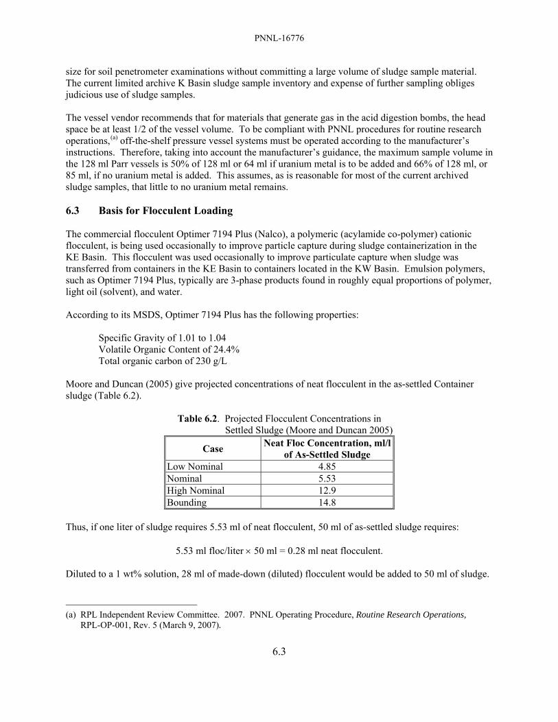
PNNL-16776
6.3
size for soil penetrometer examinations without committing a large volume of sludge sample material. The current limited archive K Basin sludge sample inventory and expense of further sampling obliges judicious use of sludge samples. The vessel vendor recommends that for materials that generate gas in the acid digestion bombs, the head space be at least 1/2 of the vessel volume. To be compliant with PNNL procedures for routine research operations,(a) off-the-shelf pressure vessel systems must be operated according to the manufacturer’s instructions. Therefore, taking into account the manufacturer’s guidance, the maximum sample volume in the 128 ml Parr vessels is 50% of 128 ml or 64 ml if uranium metal is to be added and 66% of 128 ml, or 85 ml, if no uranium metal is added. This assumes, as is reasonable for most of the current archived sludge samples, that little to no uranium metal remains. 6.3 Basis for Flocculent Loading The commercial flocculent Optimer 7194 Plus (Nalco), a polymeric (acylamide co-polymer) cationic flocculent, is being used occasionally to improve particle capture during sludge containerization in the KE Basin. This flocculent was used occasionally to improve particulate capture when sludge was transferred from containers in the KE Basin to containers located in the KW Basin. Emulsion polymers, such as Optimer 7194 Plus, typically are 3-phase products found in roughly equal proportions of polymer, light oil (solvent), and water. According to its MSDS, Optimer 7194 Plus has the following properties: Specific Gravity of 1.01 to 1.04 Volatile Organic Content of 24.4% Total organic carbon of 230 g/L Moore and Duncan (2005) give projected concentrations of neat flocculent in the as-settled Container sludge (Table 6.2).
Table 6.2. Projected Flocculent Concentrations in Settled Sludge (Moore and Duncan 2005)
Case Neat Floc Concentration, ml/l of As-Settled Sludge
Low Nominal 4.85 Nominal 5.53 High Nominal 12.9 Bounding 14.8
Thus, if one liter of sludge requires 5.53 ml of neat flocculent, 50 ml of as-settled sludge requires:
5.53 ml floc/liter × 50 ml = 0.28 ml neat flocculent. Diluted to a 1 wt% solution, 28 ml of made-down (diluted) flocculent would be added to 50 ml of sludge.
(a) RPL Independent Review Committee. 2007. PNNL Operating Procedure, Routine Research Operations,
RPL-OP-001, Rev. 5 (March 9, 2007).

PNNL-16776
6.4
Alternatively, if the bounding value is used, 75 ml (28 ml × 14.8 ml/5.53 ml) of 1 wt% made-down flocculent would be added. Note, however, that adding 75 ml of neat flocculent to 100 ml of sludge would be difficult in the hot cell environment and would not be typical of the sludge conditions. Based on a collaborative decision between PNNL and Fluor Hanford (FH) personnel in planning the prior STP process testing, use of the nominal flocculent loading is recommended for those tests requiring flocculent addition.

PNNL-16776
7.1
7.0 Description of Sludge Materials for Use in Testing and Test Matrices Sludge materials from the K Basins, simulated sludge materials prepared from un-irradiated depleted uranium metal (uraninite and metaschoepite), and non-radioactive simulated sludge materials will be used in experiments under this Test Plan. The properties of the sludge and simulant materials are described in this section. 7.1 K Basin Sludge Materials for Hot Testing Existing archived KE Floor, Pit, and Canister sludge samples were collected between 1995 and 2003, and have been stored at hot cell temperatures (~30°C) or room temperature (~20°C, for KE North Loadout Pit, KE NLOP, only) since collection. It is likely that uranium metal and U(IV) oxide (such as uraninite, UO2.x, where x ranges from 0 to 0.33) within the sludge samples continued to oxidize to form U(VI) oxyhydroxides (such as metaschoepite, UO3·2H2O) and that iron/aluminum hydroxides [Fe(OH)3 and Al(OH)3] continued to dehydrate to form oxyhydroxides (e.g., FeOOH, AlOOH) during the storage and active periodic water replenishment (for hot cell samples). At the same time, sludge in the KE Basin has undergone aggressive agitation, mixing, and aeration in sludge transfer and containerization operations at ~12°C. It is expected that both fresh (i.e., at K Basins) and aged sludge (from hot cell storage) are tending to the same state of oxidation and dehydration and would be taken to equilibrium (to complete reaction) by acceleration of the uranium metal oxidation dehydration reactions during hydrothermal treatment by STP processing. Therefore, results from hydrothermal testing with the existing archived sludge samples are judged to represent the anticipated behavior of sludge in the STP corrosion process. Only well characterized K Basin sludge sample material that has been archived and maintained wetted or near-wetted state since the time of sample collection or has been reconstituted in water will be used for the “hot” testing. Reconstitution involves re-wetting and followed by high speed blending and homogenization to disaggregate agglomerates. The goal of the “hot” testing under Test Series 1.1, 2.2, 2.3, and 3.4 is to measure strengths of STP process sludge products encompassing the range of the Container and Settler sludge inventories in the K Basins. The compositions of the K East floor and pit sludges (Makenas et al. 1996) and the KE NLOP sludge (Shelor et al. 2004) were examined to estimate the plausible range of Container sludge compositions. The examinations were limited to the contributions of the four elements most prevalent in the sludge – aluminum, iron, silicon, and uranium – whose compounds represent ~95 wt% of the sludge solids. Because acid digestion was used to analyze the K East floor and pit sludges and acid digestion is not effective for most silicates, reliable silicon concentrations are not available. Instead, the concentrations of the acid-insoluble residues presented in the analysis report were assumed to represent silicon as SiO2 except for sample KES-H-08 (sample 8) which is known to be rich in OIER. Quartz (SiO2) is frequently identified in KE floor and pit sludge. The compositions of Settler sludge are expected to be dominated by uranium (Schmidt 2006). The concentrations of aluminum, iron, silicon, and uranium in the dry K East floor and pit sludge samples, and their average composition, are shown in Figure 7.1. The average K East floor and pit sludge composition is compared in Figure 7.2 with the compositions of KE NLOP sludge, the KE Container Composite and Settler sludge used in the prior testing (Delegard et al. 2007), and the compositions of candidate sludges proposed for future testing (KC Floor Comp, FE-5, KE NLOP, KC-4, KC-2/3, and KE Floc Comp). Also given in Figure 7.2 are the compositions of the constituent sludges used in the creation of the KE Floor Comp and KE Floc Comp sludges. For KE Floor Comp, they are KC-4 and KC-5. For KE Floc Comp, they are KC-4 M250 (not analyzed but assumed to

PNNL-16776
7.2
be near in composition to that of KC-4 as KC-4 M250 is 90 wt% of KC-4), KC-5, FE-5, and KC Can Comp. The KE Floc Comp sludge was prepared in 2004 and contains high concentrations of Nalco “Optimer 7194 Plus” flocculating agent. The candidate sludges for the Test Series 1.1 and 2.2 experiments were selected from those sludges comprising the bulk of the material available in the RPL archive sludge samples. These sludges are judged to be suitable to investigate the roles of sludge composition on product quality. Another sludge in the RPL archives potentially useful for testing is KC-1 M500 (uranium-rich and ~100 ml volume; this is the <500 μm fraction of a single-pull sample of a canister containing highly damaged fuel). Although the M500 fraction of KC-1 was not analyzed separately, it represents 95.4 wt% of the total KC-1 (dry basis; Bredt et al. 1999). Therefore, the composition of KC-1 shown in Figure 7.2 should be a good approximation of the composition of the available KC-1 M500 fraction. A number of uranium-rich KE canister sludge samples having from ~50 to >400 ml volume also are available. Most of the KE canister sludge samples are high in uranium concentration (81 to 88 wt% uranium; 96-01, 96-05, 96-09, 96-13, and 96-15). Two of the KE canister sludges, 96-08 and 96-11, have lower uranium concentration (40 and 9 wt%, respectively). Sample 96-11 was taken from an empty canister and thus is more representative of floor sludge. Finally, significant quantities of KC-6 (>125 ml; consolidated sample from a KE Basin floor area high in spilled OIER) are available for testing. The compositions of the sludges (including the flocculated KE Container Comp used in the 2006 STP testing) and, for blends, the compositions of their constituent sludges in Figure 7.2 are provided in Table 7.1.

PNNL-16776
7.3
0
100000
200000
300000
400000
500000
600000
700000
1 2 3 4 5 6 8 9 10 11 12 15 16 17 18 19 20 21 23
Flr-
Pit A
vg
Source
Dry
Mas
s C
ompo
sitio
n, μ
g/g
Al Fe Si U
Floor and Pit SludgeAl: 5.9 ± 3.1 wt%Fe: 27 ± 12 wt%Si: 7.5 ± 5.0 wt% (acid-insoluble residue)U: 9.9 ± 10 wt%
Figure 7.1. Compositions of KE Floor and Pit Sludges and Their Average
0
100000
200000
300000
400000
500000
600000
700000
Flr-
Pit A
vg
KC
-1
KC
-2/3
Who
le
KC
-4
KC
-5
FE-5
KE
NLO
P
KC
Flo
or C
omp
KC
Can
Com
p
KE
Floc
Com
p
KE
Con
t Com
pFl
oc
KC
-2/3
M25
0
Source
Dry
Mas
s C
ompo
sitio
n, μ
g/g
Al Fe Si U
Hig
h A
lC
onta
inerHig
h Fe
Con
tain
er Hig
h Si
Con
tain
er
Con
tain
erSl
udge
Tes
t
Con
tain
erSl
udge
Settl
erSl
udge
Settl
erSl
udge
Tes
t
Age
d Fl
oc.
Con
tain
e r
Figure 7.2. Compositions of Candidate Sludges for Future Testing.
KE Container Comp sludge and KC-2/3 M250 Settler sludge compositions from the prior testing are shown on the right. Note that the composition of KE Container Comp Floc on a dry basis is identical to that of KE Container Comp.
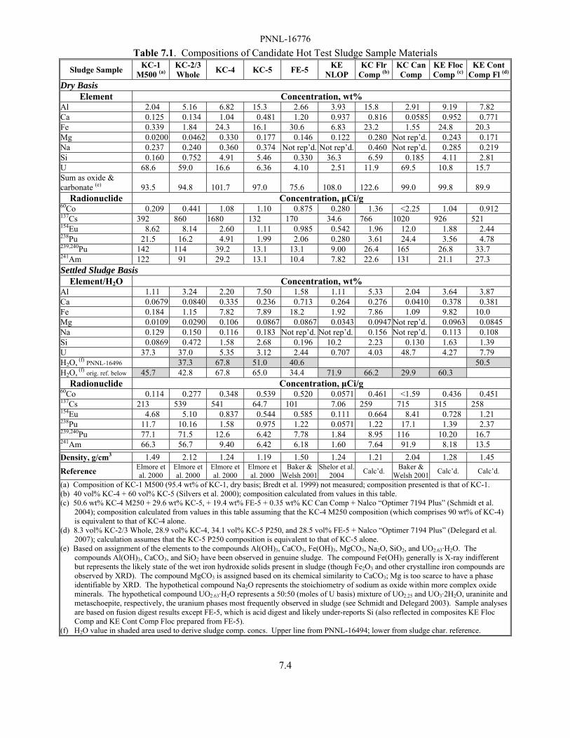
PNNL-16776
7.4
Table 7.1. Compositions of Candidate Hot Test Sludge Sample Materials Sludge Sample KC-1
M500 (a) KC-2/3 Whole KC-4 KC-5 FE-5 KE
NLOP KC Flr
Comp (b) KC Can Comp
KE Floc Comp (c)
KE Cont Comp Fl (d)
Dry Basis Element Concentration, wt%
Al 2.04 5.16 6.82 15.3 2.66 3.93 15.8 2.91 9.19 7.82 Ca 0.125 0.134 1.04 0.481 1.20 0.937 0.816 0.0585 0.952 0.771 Fe 0.339 1.84 24.3 16.1 30.6 6.83 23.2 1.55 24.8 20.3 Mg 0.0200 0.0462 0.330 0.177 0.146 0.122 0.280 Not rep’d. 0.243 0.171 Na 0.237 0.240 0.360 0.374 Not rep’d. Not rep’d. 0.460 Not rep’d. 0.285 0.219 Si 0.160 0.752 4.91 5.46 0.330 36.3 6.59 0.185 4.11 2.81 U 68.6 59.0 16.6 6.36 4.10 2.51 11.9 69.5 10.8 15.7 Sum as oxide & carbonate (e) 93.5 94.8 101.7 97.0 75.6 108.0 122.6 99.0 99.8 89.9
Radionuclide Concentration, μCi/g 60Co 0.209 0.441 1.08 1.10 0.875 0.280 1.36 <2.25 1.04 0.912 137Cs 392 860 1680 132 170 34.6 766 1020 926 521 154Eu 8.62 8.14 2.60 1.11 0.985 0.542 1.96 12.0 1.88 2.44 238Pu 21.5 16.2 4.91 1.99 2.06 0.280 3.61 24.4 3.56 4.78 239,240Pu 142 114 39.2 13.1 13.1 9.00 26.4 165 26.8 33.7 241Am 122 91 29.2 13.1 10.4 7.82 22.6 131 21.1 27.3 Settled Sludge Basis
Element/H2O Concentration, wt% Al 1.11 3.24 2.20 7.50 1.58 1.11 5.33 2.04 3.64 3.87 Ca 0.0679 0.0840 0.335 0.236 0.713 0.264 0.276 0.0410 0.378 0.381 Fe 0.184 1.15 7.82 7.89 18.2 1.92 7.86 1.09 9.82 10.0 Mg 0.0109 0.0290 0.106 0.0867 0.0867 0.0343 0.0947 Not rep’d. 0.0963 0.0845 Na 0.129 0.150 0.116 0.183 Not rep’d. Not rep’d. 0.156 Not rep’d. 0.113 0.108 Si 0.0869 0.472 1.58 2.68 0.196 10.2 2.23 0.130 1.63 1.39 U 37.3 37.0 5.35 3.12 2.44 0.707 4.03 48.7 4.27 7.79 H2O, (f) PNNL-16496 37.3 67.8 51.0 40.6 50.5 H2O, (f) orig. ref. below 45.7 42.8 67.8 65.0 34.4 71.9 66.2 29.9 60.3
Radionuclide Concentration, μCi/g 60Co 0.114 0.277 0.348 0.539 0.520 0.0571 0.461 <1.59 0.436 0.451 137Cs 213 539 541 64.7 101 7.06 259 715 315 258 154Eu 4.68 5.10 0.837 0.544 0.585 0.111 0.664 8.41 0.728 1.21 238Pu 11.7 10.16 1.58 0.975 1.22 0.0571 1.22 17.1 1.39 2.37 239,240Pu 77.1 71.5 12.6 6.42 7.78 1.84 8.95 116 10.20 16.7 241Am 66.3 56.7 9.40 6.42 6.18 1.60 7.64 91.9 8.18 13.5
Density, g/cm3 1.49 2.12 1.24 1.19 1.50 1.24 1.21 2.04 1.28 1.45
Reference Elmore et al. 2000
Elmore et al. 2000
Elmore et al. 2000
Elmore et al. 2000
Baker & Welsh 2001
Shelor et al. 2004 Calc’d. Baker &
Welsh 2001 Calc’d. Calc’d.
(a) Composition of KC-1 M500 (95.4 wt% of KC-1, dry basis; Bredt et al. 1999) not measured; composition presented is that of KC-1. (b) 40 vol% KC-4 + 60 vol% KC-5 (Silvers et al. 2000); composition calculated from values in this table. (c) 50.6 wt% KC-4 M250 + 29.6 wt% KC-5, + 19.4 wt% FE-5 + 0.35 wt% KC Can Comp + Nalco “Optimer 7194 Plus” (Schmidt et al.
2004); composition calculated from values in this table assuming that the KC-4 M250 composition (which comprises 90 wt% of KC-4) is equivalent to that of KC-4 alone.
(d) 8.3 vol% KC-2/3 Whole, 28.9 vol% KC-4, 34.1 vol% KC-5 P250, and 28.5 vol% FE-5 + Nalco “Optimer 7194 Plus” (Delegard et al. 2007); calculation assumes that the KC-5 P250 composition is equivalent to that of KC-5 alone.
(e) Based on assignment of the elements to the compounds Al(OH)3, CaCO3, Fe(OH)3, MgCO3, Na2O, SiO2, and UO2.63·H2O. The compounds Al(OH)3, CaCO3, and SiO2 have been observed in genuine sludge. The compound Fe(OH)3 generally is X-ray indifferent but represents the likely state of the wet iron hydroxide solids present in sludge (though Fe2O3 and other crystalline iron compounds are observed by XRD). The compound MgCO3 is assigned based on its chemical similarity to CaCO3; Mg is too scarce to have a phase identifiable by XRD. The hypothetical compound Na2O represents the stoichiometry of sodium as oxide within more complex oxide minerals. The hypothetical compound UO2.63·H2O represents a 50:50 (moles of U basis) mixture of UO2.25 and UO3·2H2O, uraninite and metaschoepite, respectively, the uranium phases most frequently observed in sludge (see Schmidt and Delegard 2003). Sample analyses are based on fusion digest results except FE-5, which is acid digest and likely under-reports Si (also reflected in composites KE Floc Comp and KE Cont Comp Floc prepared from FE-5).
(f) H2O value in shaded area used to derive sludge comp. concs. Upper line from PNNL-16494; lower from sludge char. reference.
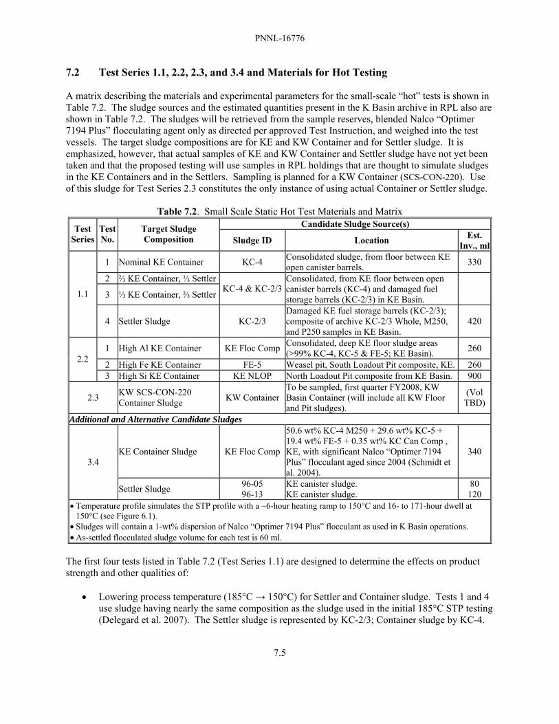
PNNL-16776
7.5
7.2 Test Series 1.1, 2.2, 2.3, and 3.4 and Materials for Hot Testing A matrix describing the materials and experimental parameters for the small-scale “hot” tests is shown in Table 7.2. The sludge sources and the estimated quantities present in the K Basin archive in RPL also are shown in Table 7.2. The sludges will be retrieved from the sample reserves, blended Nalco “Optimer 7194 Plus” flocculating agent only as directed per approved Test Instruction, and weighed into the test vessels. The target sludge compositions are for KE and KW Container and for Settler sludge. It is emphasized, however, that actual samples of KE and KW Container and Settler sludge have not yet been taken and that the proposed testing will use samples in RPL holdings that are thought to simulate sludges in the KE Containers and in the Settlers. Sampling is planned for a KW Container (SCS-CON-220). Use of this sludge for Test Series 2.3 constitutes the only instance of using actual Container or Settler sludge.
Table 7.2. Small Scale Static Hot Test Materials and Matrix Candidate Sludge Source(s) Test
Series Test No.
Target Sludge Composition Sludge ID Location Est.
Inv., ml
1 Nominal KE Container KC-4 Consolidated sludge, from floor between KE open canister barrels. 330
2 ⅔ KE Container, ⅓ Settler
3 ⅓ KE Container, ⅔ Settler KC-4 & KC-2/3Consolidated, from KE floor between open canister barrels (KC-4) and damaged fuel storage barrels (KC-2/3) in KE Basin.
1.1
4 Settler Sludge KC-2/3 Damaged KE fuel storage barrels (KC-2/3); composite of archive KC-2/3 Whole, M250, and P250 samples in KE Basin.
420
1 High Al KE Container KE Floc Comp Consolidated, deep KE floor sludge areas (>99% KC-4, KC-5 & FE-5; KE Basin). 260
2 High Fe KE Container FE-5 Weasel pit, South Loadout Pit composite, KE. 260 2.2
3 High Si KE Container KE NLOP North Loadout Pit composite from KE Basin. 900
2.3 KW SCS-CON-220 Container Sludge KW Container
To be sampled, first quarter FY2008, KW Basin Container (will include all KW Floor and Pit sludges).
(Vol TBD)
Additional and Alternative Candidate Sludges
KE Container Sludge KE Floc Comp
50.6 wt% KC-4 M250 + 29.6 wt% KC-5 + 19.4 wt% FE-5 + 0.35 wt% KC Can Comp , KE, with significant Nalco “Optimer 7194 Plus” flocculant aged since 2004 (Schmidt et al. 2004).
340 3.4
Settler Sludge 96-05 96-13
KE canister sludge. KE canister sludge.
80 120
• Temperature profile simulates the STP profile with a ~6-hour heating ramp to 150°C and 16- to 171-hour dwell at 150°C (see Figure 6.1).
• Sludges will contain a 1-wt% dispersion of Nalco “Optimer 7194 Plus” flocculant as used in K Basin operations. • As-settled flocculated sludge volume for each test is 60 ml.
The first four tests listed in Table 7.2 (Test Series 1.1) are designed to determine the effects on product strength and other qualities of:
• Lowering process temperature (185°C → 150°C) for Settler and Container sludge. Tests 1 and 4 use sludge having nearly the same composition as the sludge used in the initial 185°C STP testing (Delegard et al. 2007). The Settler sludge is represented by KC-2/3; Container sludge by KC-4.

PNNL-16776
7.6
• Blending Settler and Container sludge. The results of the four tests will determine the effects of uranium concentration on sludge strength; i.e., if strength decreases with uranium concentration. A spectrum of uranium concentrations is found in the K Basins, and containerization activities further blended these sludges (to some degree). A range of uranium concentrations therefore is likely in STP processing.
Other measured qualities are product density, water concentration, pH phase changes, and particle sizes. The three tests in Test Series 2.2 (1, 2, and 3) are designed to determine the effects of high aluminum, iron, and silicon concentrations on product strength and other qualities. According to the compositional data and the test matrix shown in Table 7.1, candidate sludges for Test Series 2.2 could be taken from KC Floor Comp for the high aluminum Container sludge (KC-5 would be a better candidate, but little KC-5 remains in inventory), from FE-5 to represent the high-iron Container sludge, and from KE NLOP for the high silicon Container sludge. The Test Series 2.3 with KW Container Sludge also could be performed provided sufficient sample is obtained during planned sampling in the first quarter of FY 2008. Samples from the floor and pits in the KW Basin have never been sampled or characterized. Currently, sludge from KW floor and pits is being consolidated into KW Container SCS-220 (SCS-CON-220). The KW West Bay floor sludge, which includes some “fuel wash” sludge from fuel and canister cleaning operations, will be recovered into this container. Based on KBC Sludge Databook projections (Schmidt 2006), the sludge to be recovered into SCS-CON-220 will have a significantly higher uranium concentration (0.28 g U/cm3) than the other Containerized sludge (nominal 93/7 volume% KE Floor/KE Canister, which contains 0.11 g U/cm3). The results from Test Series 2.3 also would provide valuable comparative data with the results obtained from Test Series 1.1 and 2.2. Alternative and additional sludge resources may be necessary for the static Test Series 3.4. One potential source representing the expected composition of Container sludge is KE Floc Comp. Additional sources representing expected Settler sludge compositions include KC-1 M500, 96-05, and 96-13, all KE canister sludges. About 60 ml of settled sludge would be necessary for each single test. However, about 120 ml of settled sludge (KC-4) would be needed to accommodate the single test (test 1 of Test Series 1.1) intended to mimic Container sludge plus the two tests (tests 2 and 3, Test Series 1.1) designed to emulate Container/Settler sludge blends. Before testing is initiated, preparatory activities must be performed. The activities include consolidation of various sub-samples into single volume-marked jars and the transfer of larger single samples from their original jars into new volume-marked jars. Numerous sub-samples were taken from primary samples for various SNF/KBC/STP support lab analyses performed from 1995 through 2006. The consolidation and re-packaging allows much improved monitoring, maintenance, and use of the remaining archive sludge samples for STP applications. For example, discrete KC-2/3 samples exist in at least nine jars. The contents of all of these jars will be combined to produce a single jar of KC-2/3 Whole. The samples will be added to a single jar with sufficient KE Basin water and blended using a small high-speed overhead mixer (as was done in the prior testing; Delegard et al. 2007). On the other hand, the FE-5 sludge, found in a single jar, will be transferred into a new volume-marked jar, KE Basin water introduced, and the FE-5 sludge blended.

PNNL-16776
7.7
Following re-packaging and blending, sludge and supernate will be sampled from each jar for analysis of settled solids density, pH, and water concentration in the settled solids (by draining and drying to constant weight at 105°C). Separate samples will be analyzed by XRD to identify the solid crystalline phases present. For uranium-rich sludges such as KC-2/3 Whole (i.e., sludges with >55 wt% uranium), the phase distribution between uraninite (UO2.x) and metaschoepite (UO3·2H2O) also may be inferred or estimated based on the particle density (see Appendix B). These data, when compared with corollary data from the hydrothermal sludge products, will quantify changes that occur during STP processing.
7.3 Test Series 3.1 and Synthetic Uraninite and Metaschoepite Sludge Materials Materials for the “warm” testing will include uraninite and metaschoepite synthesized specifically for the testing under conditions near-prototypical of those in the K Basins. The uraninite phase, UO2.x, will be synthesized by Material Sciences Corporation (MSC) of Oak Ridge, Tennessee. To match the properties of the UO2.x found in the K Basin sludge, the UO2.x will be produced at MSC by the reaction of uranium metal turnings (chips) in anoxic water. The turnings will be shaved from massive uranium metal pieces with machining equipment, the turnings washed free of the accompanying cutting fluid, and the turnings placed in anoxic water for reaction. Uranium metal reacts slowly in anoxic water at K Basin temperatures (~0.0021 μm/h at 15°C). Therefore, the reaction will be conducted at 60°C (reaction rate ~0.1 μm/h), a rate increase of a factor of ~50. The 10 kg MSC uraninite product will be shipped to PNNL in two batches in water to impede air oxidation. Both batches will arise from the same starting material; the initial ~500-g batch will be harvested early to allow initiation of small scale testing under the current program. The ~9.5 kg balance will be reserved for additional small scale testing and the larger scale mixing tests. Characterization tests by XRD and SEM will be done on separate samples of on-hand uranium metal beads (~500-μm particles) corroded in the RPL at ~20°C and 80°C to determine what morphological differences, if any, exist by corroding this uranium metal at the two differing temperatures. The purity of the uranium metal used in the RPL tests is unknown, but prior energy dispersive x-ray spectroscopy shows that the metal is unalloyed. The uraninite will be produced at MSC by corroding nearly pure uranium metal in water at ~60°C. The vendor material specifications show non-uranium constituent concentrations lower than those found in N Reactor fuel. The uranium is depleted in 235U concentration (approximately 0.2% 235U) versus 0.72% 235U in natural uranium. The balance is nearly all 238U. Being depleted, the uranium has slightly lower specific activity than natural uranium but much lower specific activity than the irradiated metallic uranium N Reactor fuel particles in genuine K Basin sludge. The influence of radiation is expected to be negligible for these tests. The properties of the MSC UO2.x 60°C product will be characterized by XRD and SEM upon receipt and the results compared with those found for the ~20°C and 80°C uranium products from the on-hand RPL sources. Metaschoepite will be produced at the RPL from the starting uraninite by reaction with aerated water. This is the likely mechanism for formation of metaschoepite in the K Basins and the reaction reportedly goes quickly for finely particulate UO2.x materials (Buck et al. 2004). Because the product of the anoxic reaction of water with uranium metal is known to produce UO2.x crystallites of sub-micron (<1 μm) dimension (Kaminski et al. 2005), the reaction to produce metaschoepite should proceed quickly. Metaschoepite samples produced by both the RPL source and MSC will undergo comparative XRD and SEM characterization to confirm the physical properties of the test materials. The XRD and SEM characteristics likewise will be compared with those found for K Basin sludge in the prior STP process testing (Delegard et al. 2007). The as-settled density and water concentrations of the uraninite and

PNNL-16776
7.8
metaschoepite test materials also will be determined to facilitate subsequent aliqouting during experimentation. The progress of the reaction to convert uraninite to metaschoepite will be followed by dissolution of the solid phases in either or both acetic acid (CH3CO2H) or ammonium carbonate [(NH4)2CO3] solution. Uranium(VI) compounds, such as metaschoepite, dissolve readily in these non-oxidizing solutions while U(IV) compounds, such as uraninite, only dissolve slowly as oxygen dissolves into the solution. The concentrations of the dissolved U(VI) will be measured by spectrophotometry. 7.4 Test Series 3.2 and 3.3 and Warm Static Testing “Warm” tests will be performed using various ratios of synthetic uraninite and metaschoepite. The test matrix proposed in Table 7.3 outlines the minimum initial static “warm” testing to understand the effects of pH and uranium phase (uraninite versus metaschoepite) under Test Series 3.2 and the effects of uranium concentration versus concentrations of other sludge constituents under Test Series 3.3. The first five tests will be performed with pH being that set by the starting phases themselves. The tests 6, 7, and 8 will be performed at starting pH between 4 and 5, 6 and 8, and >8 (pH adjustment will be by addition of nitric acid, calcium carbonate, and calcium hydroxide, respectively, and as determined by experiment). Test 9 in Series 3.3 will be conducted with the selected pH amendments and will also include uranium metal pieces to confirm the expectation that the rate of uranium oxidation by water is not affected by the amendments. Tests Series 3.2 and 3.3 will be performed under STP process conditions appropriate to the sludge composition (16 hours at 150°C for uranium-rich Settler sludge compositions).
Table 7.3. Small Scale Static Warm 150°C Matrix for Test Series 3.2 and 3.3
Test Series
Test No. Target Sludge Composition, weight basis pH Temp., °C,
Time, h 1 90 wt% uraninite in 10 wt% SiO2 Set by phases 150 / 16 2 60 wt% uraninite & 30 wt% metaschoepite in 10 wt% SiO2 Set by phases 150 / 16 3 45 wt% uraninite & 45 wt% metaschoepite in 10 wt% SiO2 Set by phases 150 / 16 4 30 wt% uraninite & 60 wt% metaschoepite in 10 wt% SiO2 Set by phases 150 / 16
3.2
5 90 wt% metaschoepite in 10 wt% SiO2 Set by phases 150 / 16 1 40 wt% uraninite & 40 wt% metaschoepite in 20 wt% SiO2 Set by phases 150 / 16 2 30 wt% uraninite & 30 wt% metaschoepite in 40 wt% SiO2 Set by phases 150 / 16 3 20 wt% uraninite & 20 wt% metaschoepite in 60 wt% SiO2 Set by phases 150 / 16 4 10 wt% uraninite & 10 wt% metaschoepite in 80 wt% SiO2 Set by phases 150 / 16 5 ~8, CaCO3 150 / 16 6 ~10, Ca(OH)2 150 / 16 7 ~7, (Na,H)3PO4 150 / 16 8
“Bounding” (highest) strength as found in Test Series 3.2
~10, Na8P3O10 150 / 16
3.3
9 Selected pH and dilution amendments TBD 150 / 16 • Temperature profile simulates the STP profile shown in Figure 3.1 with 16-h dwell at 150°C for all tests. • As-settled sludge volume for each test is 60-ml.
The tests outlined in Table 7.3, in concert with the “hot” testing described in Section 7.2, will help confirm or refute the supposition that the uranium phases uraninite and particularly metaschoepite are responsible for driving the shear strengths of the STP process sludge. Tests 1-5 in Test Series 3.2 are designed to determine whether metaschoepite or uraninite is more responsible for the higher product strengths. The tests will also identify the ratio producing the greatest product strength (i.e., the formulation producing the “bounding” strength). This is important for subsequent pH / chemical
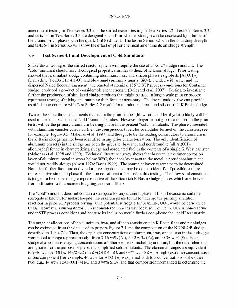
PNNL-16776
7.9
amendment testing in Test Series 3.3 and the stirred reactor testing in Test Series 4.2. Test 3 in Series 3.2 and tests 1-4 in Test Series 3.3 are designed to confirm whether strength can be decreased by dilution of the uranium-rich phases with the quartz (SiO2) diluent. The test in Series 3.2 with the bounding strength and tests 5-8 in Series 3.3 will show the effect of pH or chemical amendments on sludge strength. 7.5 Test Series 4.1 and Development of Cold Simulants Shake-down testing of the stirred reactor system will require the use of a “cold” sludge simulant. The “cold” simulant should have rheological properties similar to those of K Basin sludge. Prior testing showed that a simulant sludge containing aluminum, iron, and silicon phases as gibbsite [Al(OH)3], ferrihydrite [Fe5O7(OH)·4H2O], and blow sand (primarily quartz, SiO2), blended with water and the dispersed Nalco flocculating agent, and reacted at nominal 185°C STP process conditions for Container sludge, produced a product of considerable shear strength (Delegard et al. 2007). Testing to investigate further the production of simulated sludge products that might be used in larger-scale pilot or process equipment testing of mixing and pumping therefore are necessary. The investigations also can provide useful data to compare with Test Series 2.2 results for aluminum-, iron-, and silicon-rich K Basin sludge. Two of the same three constituents as used in the prior studies (blow sand and ferrihydrite) likely will be used in the small scale static “cold” simulant studies. However, bayerite, not gibbsite as used in the prior tests, will be the primary aluminum-bearing phase in the present “cold” simulants. The phase associated with aluminum canister corrosion (i.e., the conspicuous tubercles or nodules formed on the canisters; see, for example, Figure 3.5, Makenas et al. 1997) and thought to be the leading contributors to aluminum in the K Basin sludge has not been identified in any prior characterization. The only identification of aluminum phase(s) in the sludge has been the gibbsite, bayerite, and nordstrandite [all Al(OH)3 allomorphs] found in characterizing sludge and associated fuel in the contents of a single K West canister (Makenas et al. 1998 and 1999). Technical literature survey shows that bayerite is the outer corrosion layer of aluminum metal in water below 90°C; the inner layer next to the metal is pseudoboehmite and would not readily slough (Alwitt 1976; Davis 1999). The source of bayerite remains to be determined. Note that further literature and vendor investigation also may be done to identify, if possible, a more representative simulant phase for the iron constituent to be used in this testing. The blow sand constituent is judged to be the best single representative of the silica-rich K Basin sludge phases which are derived from infiltrated soil, concrete sloughing, and sand filters. The “cold” simulant does not contain a surrogate for any uranium phase. This is because no suitable surrogate is known for metaschoepite, the uranium phase found to undergo the primary alteration reactions in prior STP process testing. One potential surrogate for uraninite, UO2, would be ceric oxide, CeO2. However, a surrogate for UO2 is considered unnecessary because, like CeO2, UO2 is non-reactive under STP process conditions and because its inclusion would further complicate the “cold” test matrix. The range of allocations of the aluminum, iron, and silicon constituents in K Basin floor and pit sludges can be estimated from the data used to prepare Figure 7.1 and the composition of the KE NLOP sludge described in Table 7.1. Thus, the dry-basis concentrations of aluminum, iron, and silicon in these sludges were noted to range (approximately) from 3-16 wt% (Al), 8-42 wt% (Fe), and 0-36 wt% (Si). Each sludge also contains varying concentrations of other elements, including uranium, but the other elements are ignored for the purpose of preparing simplified cold simulants. The elemental ranges are equivalent to 9-46 wt% Al(OH)3, 14-72 wt% Fe5O7(OH)·4H2O, and 0-77 wt% SiO2. A high (extreme) concentration of one component [for example, 46 wt% for Al(OH)3] was paired with low concentrations of the other two [e.g., 14 wt% Fe5O7(OH)·4H2O and 0 wt% SiO2] and that composition normalized to determine the

PNNL-16776
7.10
composition, for this example, of an aluminum-rich and uranium-free sludge. Similar compositions were derived for iron-and silicon-rich sludges. The normalized extreme sludge component value ranges were 9-77 wt% Al(OH)3, 14-89 wt% Fe5O7(OH)·4H2O, and 0-78 wt% SiO2. The composition of the Al(OH)3 (bayerite), Fe5O7(OH)·4H2O (ferrihydrite), and blow sand (primarily SiO2) mixtures are presented analogously to a ternary phase diagram (Figure 7.3). The compositions considered for testing do not encompass the entire 0-100 wt% range but rather just the approximate range observed for these three contributors on a normalized basis in the K Basin floor and pit sludges. For simplicity, the range to be tested is 10-90 wt% bayerite and ferrihydrite and 0-80 wt% blow sand. The proposed testing matrix for these non-radioactive experiments is given in Table 7.4. The symmetry of the matrix depicted in Figure 7.3 achieves uniform coverage of the desired compositional space.
Table 7.4. Small Scale Static Cold Test Matrix Test Number Target Sludge Composition, fractional weight basis
1 0.90 bayerite, 0.10 ferrihydrite 2 0.90 ferrihydrite, 0.10 bayerite 3 0.80 blow sand, 0.10 ferrihydrite, 0.10 bayerite 4 0.366 bayerite, 0.366 ferrihydrite, 0.266 blow sand 5 0.633 bayerite, 0.233 ferrihydrite, 0.133 blow sand 6 0.233 bayerite, 0.633 ferrihydrite, 0.133 blow sand 7 0.233 bayerite, 0.233 ferrihydrite, 0.533 blow sand 8 0.50 bayerite, 0.50 ferrihydrite, 0 blow sand 9 0.50 bayerite, 0.10 ferrihydrite, 0.40 blow sand
10 0.10 bayerite, 0.50 ferrihydrite, 0.40 blow sand • Temperature profile simulates the STP profile shown in Figure 3.1, as appropriate for Container sludge, with 171-h
dwell at 150°C. • As-settled flocculated sludge volume for each test is 60-ml.
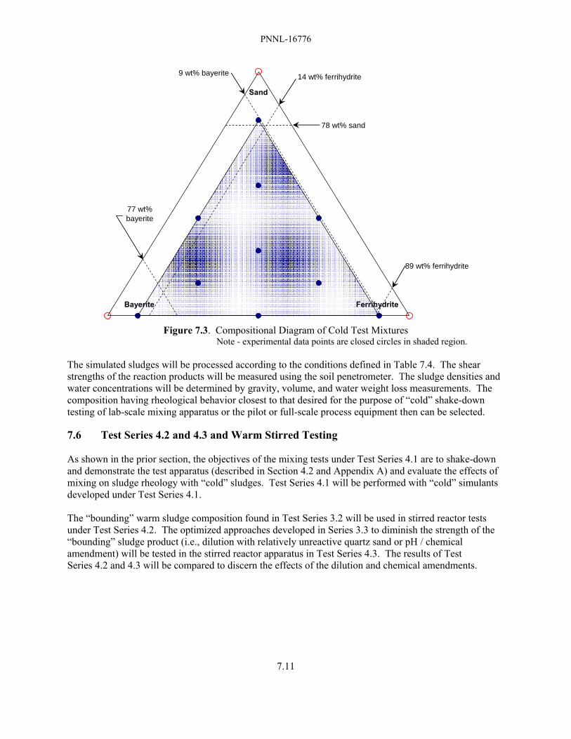
PNNL-16776
7.11
Bayerite Ferrihydrite
Sand
78 wt% sand
14 wt% ferrihydrite
89 wt% ferrihydrite
9 wt% bayerite
77 wt%bayerite
Figure 7.3. Compositional Diagram of Cold Test Mixtures
Note - experimental data points are closed circles in shaded region. The simulated sludges will be processed according to the conditions defined in Table 7.4. The shear strengths of the reaction products will be measured using the soil penetrometer. The sludge densities and water concentrations will be determined by gravity, volume, and water weight loss measurements. The composition having rheological behavior closest to that desired for the purpose of “cold” shake-down testing of lab-scale mixing apparatus or the pilot or full-scale process equipment then can be selected. 7.6 Test Series 4.2 and 4.3 and Warm Stirred Testing As shown in the prior section, the objectives of the mixing tests under Test Series 4.1 are to shake-down and demonstrate the test apparatus (described in Section 4.2 and Appendix A) and evaluate the effects of mixing on sludge rheology with “cold” sludges. Test Series 4.1 will be performed with “cold” simulants developed under Test Series 4.1. The “bounding” warm sludge composition found in Test Series 3.2 will be used in stirred reactor tests under Test Series 4.2. The optimized approaches developed in Series 3.3 to diminish the strength of the “bounding” sludge product (i.e., dilution with relatively unreactive quartz sand or pH / chemical amendment) will be tested in the stirred reactor apparatus in Test Series 4.3. The results of Test Series 4.2 and 4.3 will be compared to discern the effects of the dilution and chemical amendments.

PNNL-16776
8.1
8.0 Post-Test Analyses Post-test analyses will be performed to discern alterations in the sludge material properties that occur during testing. The objectives of the testing are to determine if STP thermal processing adversely affects subsequent sludge retrieval, processing, or transport. Goals also include determining if sludge strength can be altered by blending or dilution. Design of non-radioactive simulants having product shear strengths similar to those of processed K Basin sludge will be done for application in pilot testing. Product properties must be measured in all of these tests to understand the influences of the STP process testing on sludge qualities. Many sludge properties also must be measured before testing. The pre-test analyses are shown, where appropriate, with the post-test analyses in Table 8.1. The post-test analyses may be augmented or certain of the tests mentioned in Table 8.1 omitted at the discretion of the cognizant scientist or engineer in light of the observed test conditions and KBC/STP test objectives (Makenas and Schmidt 2007).
Table 8.1. Sequence of Post-Test Analysis Steps for Each Test Vessel and Rationale Post-Test Step Pre-Test Rationale and Data Objectives
Weigh vessel Yes Determine weight loss (likely as water evaporation) Open vessel No N/A Prepare video record of inside vessel No Examine for evidence of water line, foaming, floating solids, “bathtub ring” Measure settled sludge supernatant volumes Yes Determine change (i.e., sludge compaction or water uptake by reaction with
solids)
Decant supernatant liquid into receiver jar Yes
For subsequent handling and archiving for potential future follow-on analyses (e.g., ion chromatography for chloride, sulfate) to characterize changes from pre-test supernatant liquid
Measure supernatant pH Yes Alteration in pH may affect STP reaction vessel corrosion
Measure depth to top of settled sludge Yes Determine, by difference, changes in settled sludge volume and allow sludge solids density determination
Probe sludge solids in vessel and record by video Yes Determine qualitative changes/differences in sludge texture; e.g., has sludge
formed a “brick”? Remove sludge from vessel and record by video No Determine qualitative sludge texture (generally contrast with pre-test
observations during loading) Probe using soil penetrometer, mix decanted sludge solids, looking for self-cementation, and record by video
Yes Provide visual images of sludge consistencies and evidence of changes in texture
Perform soil penetrometer test of sludge No Analysis appropriate to obtain shear strength values of
compacted/agglomerated sludge Retrieve sample for water erosion testing No Optional testing. Provide further evidence of sludge strength
Determine weight percent water in settled sludge Yes Determine changes in void fraction (volume fraction water)
Determine settled sludge density Yes Determine changes in sludge density (i.e., compaction or expansion, gas retention)
Examine and probe vessel wall and record by video No Look for adhering sludge and for staining on stainless steel vessel wall; look
again for evidence of foaming If judged useful, obtain sieve analyses of sludge solids; record by masses of separated fractions and by video
No Preliminary examinations will determine if this analysis is useful (e.g., if agglomeration to form larger particles, short of “brick”, is noted); fractions will be collected using 4000, 2000, 1000, 500, and 250-μm sieves as appropriate
Perform, if appropriate, compacted sludge attrition measurements with overhead stirrer
No Analysis appropriate to determine propensity of compacted/agglomerated sludge to remobilize by agitation
Analyze product solids by XRD, SEM, and EDS Yes Phase changes between starting materials and products indicate reactions

PNNL-16776
9.1
9.0 References Abrefah, J, AW Etchells III, and RGG Holmes. 2007. Report on Expert Review of the Sludge Treatment Project Testing, PNNL-16643, Pacific Northwest National Laboratory, Richland, WA. Prepared for Fluor Hanford and BNG America. Alwitt, RS. 1976. “The Aluminum-Water System,” Chapter 3 in Volume 4, Oxides and Oxide Films, of The Anodic Behavior of Metals and Semiconductors Series, JW Diggle and AK Vijh, editors, Marcel Dekker, Inc., New York, NY. Baker, RB and TL Welsh. 2001. “Summary of Initial Laboratory Data from the Consolidated and Single Pull Core Sludge Sampling Campaigns,” letter report 01-SNF/RBB-004 to KL Pearce, Spent Nuclear Fuel Project, Fluor Hanford, Richland, WA (May 10, 2001). Baker, RB, TL Welsh, and BJ Makenas. 2000. Sampling and Analysis Plan for Sludge from the 105K Basins to Support Transport to and Storage in T Plant. HNF-6479, Fluor Hanford Company, Richland WA. Bredt, PR, CH Delegard, AJ Schmidt, and KL Silvers. 1999. Testing and Analysis of Consolidated Sludge Sample from 105K East Basin Floor and Canisters. PNNL-13341, Pacific Northwest National Laboratory, Richland, WA. Bryan SA, CH Delegard, AJ Schmidt, RL Sell, KL Silvers, SR Gano, and BM Thornton. 2004. Gas Generation from K East Basin Sludges – Series II Testing. PNNL-13446, Rev. 1, Pacific Northwest National Laboratory, Richland, WA. Buck, EC, BK McNamara, and BD Hanson. 2004. Alternative Conceptual Model for Colloid Generation from Commercial Spent Nuclear Fuel. PNNL-14306, Pacific Northwest National Laboratory, Richland, WA. CRC. 1968. Handbook of Chemistry and Physics, The Chemical Rubber Company, Inc., Cleveland, OH. Davis, JR. 1999. Corrosion of Aluminum and Aluminum Alloys, p. 32, ASM International, Materials Park, OH. Delegard, CH, SA Bryan, AJ Schmidt, PR Bredt, CM King, RL Sell, LL Burger, and KL Silvers. 2000. Gas Generation from K East Basin Sludges – Series I Testing. PNNL-13320, Pacific Northwest National Laboratory, Richland, WA. Delegard, CH, AP Poloski, AJ Schmidt, and JW Chenault. 2005. Characterization of Compaction and Dryout Properties of KE Basin Sludge During Long-Term Storage. PNNL-15092, Pacific Northwest National Laboratory, Richland, WA. Delegard, CH, AJ Schmidt, and BM Thornton. 2007. Hydrothermal Testing of K Basin Sludge and N Reactor Fuel at Sludge Treatment Project Operating Conditions. PNNL-16496, Pacific Northwest National Laboratory, Richland, WA.

PNNL-16776
9.2
Elmore, MR, AJ Schmidt, KL Silvers, BM Thornton, and SR Gano. 2000. Chemical and Radiochemical Analysis of Consolidated Sludge Samples from K East Basin. PNNL-13360, Pacific Northwest National Laboratory, Richland, WA. EPA. 1992. Guidance for Conducting Treatability Studies Under CERCLA. EPA/540/R-92/071a, U.S. Environmental Protection Agency, Washington, DC. EPA. 1994. Guidance for Planning for Data Collection in Support of Environmental Decision Making Using the Data Quality Objectives Process. EPA QA/G-4, U.S. Environmental Protection Agency, Washington, DC. Finch, R and T Murakami. 1999. “Systematics and Paragenesis of Uranium Minerals,” chapter 3 of Uranium – Mineralogy, Geochemistry and the Environment, PC Burns and R Finch, editors, The Mineralogical Society of America, Washington, DC. Heywood, N. 2006. Report on Conclusions of Independent Review Panel for K Basin Closure Stabilization and Packaging Project Process. CR 7736, BNG America, Wharley End, UK. Kaminski, MD, NM Dimitrijevic, CJ Mertz, and MM Goldberg. 2005. “Colloids from the Aqueous Corrosion of Uranium Nuclear Fuel,” Journal of Nuclear Materials 347:77-87. Lawrence, LA. 1994. Spent Nuclear Fuel Project Characterization Data Quality Objectives Strategy. WHC-EP-0795, Rev. 0, Westinghouse Hanford Company, Richland, WA. Makenas, BJ and AJ Schmidt. 2007. Data Quality Objectives for Process Testing of K Basin Sludge. HNF-33942, Rev. 0, Fluor Hanford Company, Richland, WA. Title change? Makenas, BJ. 2007. Data Quality Objectives for Sampling of K West Basin Floor and Pit Sludges in a Large Engineered Container. KBC-32318, Fluor Hanford Company, Richland, WA. Makenas, BJ. 2000. Data Quality Objectives for Analysis of Hanford K Basin Sludge to Support Transport to and Storage in T Plant. HNF-5345, Rev 0, Fluor Hanford Company, Richland, WA. Makenas, BJ. 1999. Data Quality Objective for K East Basin Canister Sludge Sampling. WHC-SD-SNF-DQO-008, Rev. 0A, Duke Engineering & Services Hanford, Inc., Richland, WA. Makenas, BJ, TL Welsh, PR Bredt, GR Golcar, AJ Schmidt, KL Silvers, JM Tingey, AH Zacher, and RB Baker. 1999. Analysis of Internal Sludge and Cladding Coatings from N-Reactor Fuel Stored in Hanford K Basins. HNF-3589, Rev. 0, Fluor Daniel Hanford, Inc., Richland, WA. Makenas, BJ. 1998. Data Quality Objective for Sampling from the K West and K East Basin Floor and From Other Basin Areas. HNF-2033, Rev. 0, Duke Engineering & Services Hanford, Inc., Richland, WA. Makenas, BJ, TL Welsh, RB Baker, GR Golcar, PR Bredt, AJ Schmidt, and JM Tingey. 1998. Analysis of Sludge from Hanford K West Basin Canisters. HNF-1728, Rev. 0, Fluor Daniel Hanford, Richland, WA.

PNNL-16776
9.3
Makenas, BJ, TL Welsh, RB Baker, EW Hoppe, AJ Schmidt, J Abrefah, JM Tingey, PR Bredt, and GR Golcar. 1997. Analysis of Sludge from Hanford K East Basin Canisters. HNF-SP-1201, Rev. 0, Duke Engineering & Services Hanford, Inc., Richland, WA. Makenas, BJ, TL Welsh, RB Baker, DR Hansen, and GR Golcar. 1996. Analysis of Sludge from Hanford K East Basin Floor and Weasel Pit. WHC-SP-1182, Rev. 0, Westinghouse Hanford Company, Richland, WA. Mellinger, GB, CH Delegard, AJ Schmidt, and GJ Sevigny. 2004. Evaluation and Recommendation of Waste Form and Packaging for Disposition of the K East Basin North Loadout Pit Sludge. PNNL-14741, Pacific Northwest National Laboratory, Richland,WA. Moore, FW and DR Duncan. 2005. K Basin Closure Project KW Sludge Containerization System Calculation to Determine Flocculent Concentrations in KW Containers. KBC-27977, Rev. 0, Fluor Hanford, Richland, WA. Pearce, KL. 2001. 105-K Basin Material Design Basis Feed Description for Spent Nuclear Fuel Project Facilities, Volume 2 (Sludge). HNF-SD-SNF-TI-009, Rev. 4, Fluor Hanford Corporation, Richland, WA. Pitner, AL. 1999. K East Basin Sludge Sampling/1999 Campaign. HNF-4746, Rev. 0, Fluor Hanford Company, Richland, WA. Pitner, AL. 1999. K East Basin Sludge/Sampling 1999 Campaigns. HNF-4746, Rev. 0, Numatec Hanford Corporation, Richland, WA. Plys, MG and AJ Schmidt. 2006. Supporting Basis for SNF Project Sludge Technical Data Book. SNF-7765, Rev. 3b, Fluor Hanford, Inc., Richland, WA. Roberts, WL, TJ Campbell, GR Rapp, and WE Wilson. 1990. Encyclopedia of Minerals, 2nd edition. Van Nostrand Reinhold, NY. Ritchie, AG. 1981. “A Review of the Rates of Reaction of Uranium with Oxygen and Water Vapour at Temperatures Up To 300°C,” Journal of Nuclear Materials 102:170-182. Schmidt, AJ. 2006. Spent Nuclear Fuel Project Databook, Volume 2, Sludge. HNF-SD-SNF-TI-015, Rev. 13, Fluor Hanford, Inc., Richland, WA. Schmidt, AJ and CH Delegard (PNNL) and RB Baker, BJ Makenas, and JP Sloughter (FH). 2006. Sludge Treatment Project Corrosion Process Chemistry Testing, Test Plan 51623-TP-01, Rev. 0, Pacific Northwest National Laboratory, Richland, WA. (Note: This document was issued for limited distribution as PNNL-16177). Schmidt, AJ, RT Hallen, DS Muzatko, and SR Gano. 2004. KE Basin Sludge Flocculant Testing. PNNL-14730, Pacific Northwest National Laboratory, Richland, WA. Schmidt, AJ, CH Delegard, SA Bryan, MR Elmore, RL Sell, KL Silvers, SR Gano, and BM Thornton. 2003. Gas Generation from K East Basin Sludges and Irradiated Metallic Uranium Fuel Particles – Series III Testing. PNNL-14346, Pacific Northwest National Laboratory, Richland, WA.

PNNL-16776
9.4
Schmidt, AJ and CH Delegard. 2003. Updated Volumetric Expansion Factors for K Basin Sludge During Storage. PNNL-14228, Pacific Northwest National Laboratory, Richland, WA. Shelor, JL, M Epstein, MG Plys, JP Sloughter, J Abrefah, CH Delegard, and AJ Schmidt. 2004. Gas Behavior in Large Diameter Containers (LDCs) During and Following Loading with 105K East North Loadout Pit Sludge. SNF-22059, Fluor Hanford, Richland, WA; see Attachment 21. Shoesmith, DW. 2000. “Review – Fuel Corrosion Processes Under Waste Disposal Conditions,” Journal of Nuclear Materials 282:1-31. Silvers, KL, JJ Wagner, and RT Steele. 2000. TCLP Preparation and Analysis of K East Basin Composite Sludge Samples. PNNL-13280, Pacific Northwest National Laboratory, Richland, WA. Trimble, DJ. 1998. Reaction Rate Constant for Uranium in Water and Water Vapor. HNF-2853, Rev. 0, Duke Engineering & Services Hanford, Inc., Richland, WA. Weakley, EA. 1979. Fuels Engineering Technical Handbook. UNI-M-61, UNC Nuclear Industries, Richland, WA. Wellman, DM, JS Fruchter, and VR Vermuel. 2006. Experimental Plan: Uranium Stabilization Through Polyphosphate Injection – 300 Area Uranium Plume Treatability Demonstration Project. PNNL-16101, Pacific Northwest National Laboratory, Richland, WA. Woodworth, M. 2006. Sludge Retrieval and Transfer System Material Balance. CALC-5477-PR-R-0001, Rev. 1, BNG America. Zheng, Z, J Wan, X Song, and TK Tokunaga. 2006. “Sodium Meta-Autunite Colloids: Synthesis, Characterization, and Stability,” Colloids and Surfaces A 274(1-3):48-55.

PNNL-16776
A.1
Appendix A
Preliminary Evaluation of Scaled Mixing Test For scaled systems at the same agitation rating (Chemineer Scale for Agitation of Solids in Suspension),(a) the required rotational rate varies as follows:
LS
LS N
DDN
75.0
⎟⎟⎠
⎞⎜⎜⎝
⎛=
Ds = Small scale length scale DL = Large scale length scale Ns = Small scale rotational rate NL = Large scale rotational rate
The large scale process vessel is compared in Figure A.1 with the small scale (1-liter laboratory-scale) vessel to show their similar proportions. Figure A.2 shows the standard dished bottom dimensions for the 1-liter laboratory-scale reactor vessel.
Figure A.1. Process Vessel Diagram (left) and Test Vessel Diagram (right)
(a) “Liquid Agitation by Chemineer.” Part 1, Chem. Eng. 1975, 110-114, to part 12, Chem. Eng. 1976,
Dec 6, 165-170.
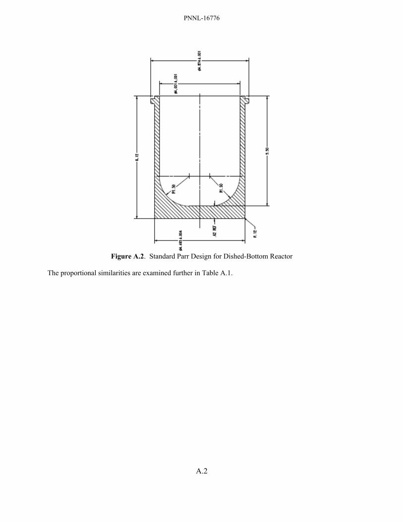
PNNL-16776
A.2
Figure A.2. Standard Parr Design for Dished-Bottom Reactor
The proportional similarities are examined further in Table A.1.
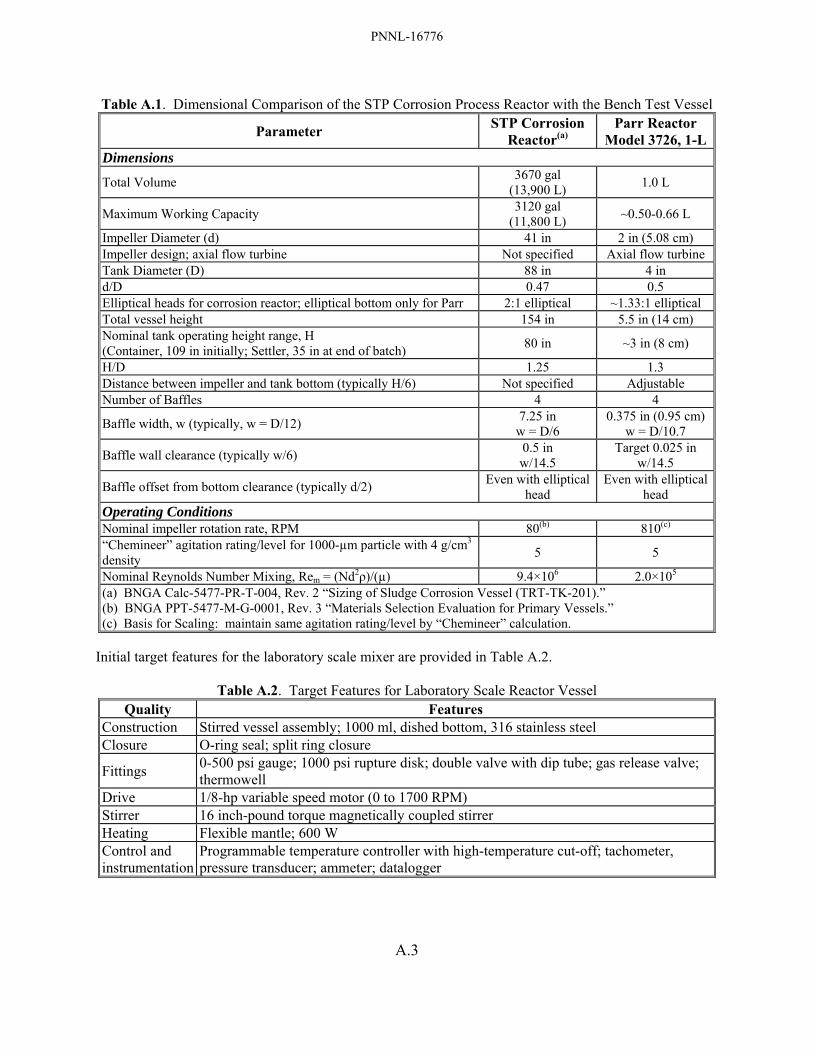
PNNL-16776
A.3
Table A.1. Dimensional Comparison of the STP Corrosion Process Reactor with the Bench Test Vessel
Parameter STP Corrosion Reactor(a)
Parr Reactor Model 3726, 1-L
Dimensions
Total Volume 3670 gal (13,900 L) 1.0 L
Maximum Working Capacity 3120 gal (11,800 L) ~0.50-0.66 L
Impeller Diameter (d) 41 in 2 in (5.08 cm) Impeller design; axial flow turbine Not specified Axial flow turbine Tank Diameter (D) 88 in 4 in d/D 0.47 0.5 Elliptical heads for corrosion reactor; elliptical bottom only for Parr 2:1 elliptical ~1.33:1 elliptical Total vessel height 154 in 5.5 in (14 cm) Nominal tank operating height range, H (Container, 109 in initially; Settler, 35 in at end of batch) 80 in ~3 in (8 cm)
H/D 1.25 1.3 Distance between impeller and tank bottom (typically H/6) Not specified Adjustable Number of Baffles 4 4
Baffle width, w (typically, w = D/12) 7.25 in w = D/6
0.375 in (0.95 cm) w = D/10.7
Baffle wall clearance (typically w/6) 0.5 in w/14.5
Target 0.025 in w/14.5
Baffle offset from bottom clearance (typically d/2) Even with elliptical head
Even with elliptical head
Operating Conditions Nominal impeller rotation rate, RPM 80(b) 810(c) “Chemineer” agitation rating/level for 1000-µm particle with 4 g/cm3 density 5 5
Nominal Reynolds Number Mixing, Rem = (Nd2ρ)/(µ) 9.4×10⁶ 2.0×10⁵ (a) BNGA Calc-5477-PR-T-004, Rev. 2 “Sizing of Sludge Corrosion Vessel (TRT-TK-201).” (b) BNGA PPT-5477-M-G-0001, Rev. 3 “Materials Selection Evaluation for Primary Vessels.” (c) Basis for Scaling: maintain same agitation rating/level by “Chemineer” calculation.
Initial target features for the laboratory scale mixer are provided in Table A.2.
Table A.2. Target Features for Laboratory Scale Reactor Vessel Quality Features
Construction Stirred vessel assembly; 1000 ml, dished bottom, 316 stainless steel Closure O-ring seal; split ring closure
Fittings 0-500 psi gauge; 1000 psi rupture disk; double valve with dip tube; gas release valve; thermowell
Drive 1/8-hp variable speed motor (0 to 1700 RPM) Stirrer 16 inch-pound torque magnetically coupled stirrer Heating Flexible mantle; 600 W Control and instrumentation
Programmable temperature controller with high-temperature cut-off; tachometer, pressure transducer; ammeter; datalogger

PNNL-16776
A.4
Qualities of the agitation rating/level are matched in the process and test vessels to the “Chemineer” scale in Table A.1; qualitative descriptions of the “Chemineer” scale are given in Table A.3.
Table A.3. Chemineer Scale for Agitation of Solids in Suspension

PNNL-16776
A.5
The density and viscosity of water as functions of temperature, used in calculating the Reynolds number, are plotted in Figure A.3.
(density)=0.34710*(0.27400^(-((1-(T/(647.13)))^(0.28571))))Temperature Range -0.1500 - 373.9 °'b0CX - Temperature (°'b0C) Y - Liquid Density (g/cm^3)
(nliq)=10 (̂-10.2158+(1.7925E+03/T)+(1.7730E-02*T)+(-1.2631E-05*(T^2)))Temperature Range -0.1500 - 369.9 °'b0CX - Temperature (°'b0C) Y - Viscosity of Liquid (cP)
Figure A.3. Density and Viscosity of Water as a Function of Temperature (°C)
The agitation rate (RPM) regimes achieved for the process-scale and bench-scale (1-liter) vessels are compared in Figure A.4. It is seen that the agitation rates for the two vessels differ by almost exactly a factor of ten to achieve the same “Chemineer” agitation level of 5, as shown in Table A.1.
Figure A.4. Agitation Levels for Process-Scale (left) and Bench-Scale Stirred Vessels
at “Chemineer” Agitation Level 5 (The agitation rates in RPM are given on the borders of the colored regions)

PNNL-16776
B.1
Appendix B
Determination of Metaschoepite Concentration in Uranium-Rich Sludges from Chemical Composition and Particle Density Data
A method to estimate the concentration of metaschoepite (UO3·2H2O) with respect to uraninite (UO2.x) in uranium-rich sludge samples was developed based on the chemical composition of the sludge, the measured particle densities of sludge, and (as applicable) the measured concentration of contained uranium metal. The method exploits the fact that uraninite particle density (~11 g/cm3) is much higher than that of other oxidized sludge components, including metaschoepite (density ~5 g/cm3). The method thus assumes that uraninite, metaschoepite, and uranium metal are the only uranium phases present in appreciable concentrations in the sludge. The method becomes much less amenable to sludge having lower uranium concentrations (e.g., <55 wt%, dry basis) because the volume contributions from other sludge phases begin to dominate. It was observed that the particle densities of the KC-2/3 M250 sludge used to model the behavior of Settler sludge in the hydrothermal testing of the STP process (Delegard et al. 2007) had particle density of 6.11 g/cm3 (estimated uncertainty of ± 0.2 g/cm3) and thus must have contained a uraninite contribution. The particle density of the same sludge measured in 1999 was 7.57 g/cm3 (Bredt et al. 1999) and likely contained an even higher uraninite fraction (its uranium metal concentration in 1999 was low, ~3300 μg/g; Bryan et al. 2004). The determinations are made using a spreadsheet in which the contributions of metaschoepite (and, by difference in the total uranium concentration, uraninite) to the total particle density are adjusted until the normalized contributions of all the components to the particle density are made to match the observed particle density. Therefore, the contributions of other sludge constituents to the total particle inventory must be accounted. The chemical concentrations were determined by inductively coupled plasma, ICP, spectroscopy for the various metallic constituent elements and laser fluorimetry for total uranium; uranium metal concentrations are determined by gas generation experiments. The concentrations, in terms of μg of analyte per gram of dry sludge, are entered into the spreadsheet and converted by gravimetric factors into μg of corresponding postulated compound (as determined by sludge characterization, where available, and chemical judgment) per gram of dry sludge. For example, if the aluminum concentration is 12,300 μg per gram of dry sludge, the corresponding compound [Al(OH)3] weight is:
sludgedryg)OH(Alg500,35
Alg27)OH(Alg78
sludgedrygAlg300,12)OH(AlionConcentrat 33
3μ
=×μ
=
The volume occupied by each solid is determined by dividing by its particle density [e.g., 2.44 g/cm3 for Al(OH)3]. Densities of non-uranium phases were obtained from handbook values (CRC 1968), metaschoepite density from Roberts et al. (1990), and Zircaloy and uranium metal fuel densities from Weakley (1979). The volumes of each solid are summed and compared with the inverse of the observed sludge particle density (i.e., the cm3 occupied per gram of dry sludge). The density of UO2.x is estimated based on the densities of UO2, UO2.25, and UO2.34 as published by the International Centre for Diffraction Data and the fit curve shown in Figure B.1. The nominal UO2.x composition is UO2.08 as taken from the work of Kaminski and colleagues (2005) and the density for this compound as obtained from Figure B.1
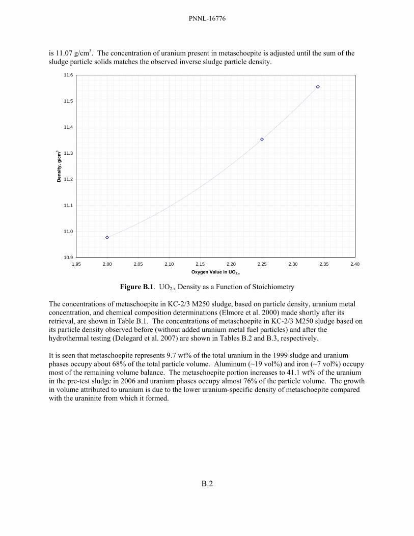
PNNL-16776
B.2
is 11.07 g/cm3. The concentration of uranium present in metaschoepite is adjusted until the sum of the sludge particle solids matches the observed inverse sludge particle density.
10.9
11.0
11.1
11.2
11.3
11.4
11.5
11.6
1.95 2.00 2.05 2.10 2.15 2.20 2.25 2.30 2.35 2.40
Oxygen Value in UO2.x
Den
sity
, g/c
m3
Figure B.1. UO2.x Density as a Function of Stoichiometry
The concentrations of metaschoepite in KC-2/3 M250 sludge, based on particle density, uranium metal concentration, and chemical composition determinations (Elmore et al. 2000) made shortly after its retrieval, are shown in Table B.1. The concentrations of metaschoepite in KC-2/3 M250 sludge based on its particle density observed before (without added uranium metal fuel particles) and after the hydrothermal testing (Delegard et al. 2007) are shown in Tables B.2 and B.3, respectively. It is seen that metaschoepite represents 9.7 wt% of the total uranium in the 1999 sludge and uranium phases occupy about 68% of the total particle volume. Aluminum (~19 vol%) and iron (~7 vol%) occupy most of the remaining volume balance. The metaschoepite portion increases to 41.1 wt% of the uranium in the pre-test sludge in 2006 and uranium phases occupy almost 76% of the particle volume. The growth in volume attributed to uranium is due to the lower uranium-specific density of metaschoepite compared with the uraninite from which it formed.
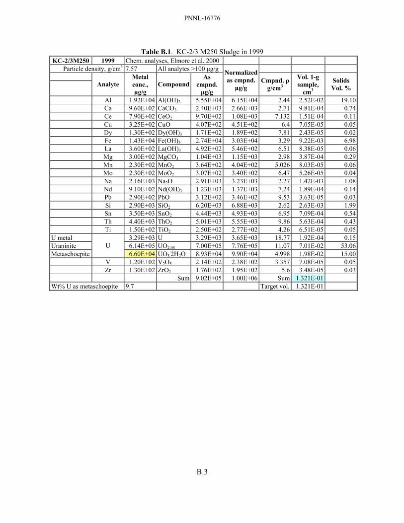
PNNL-16776
B.3
Table B.1. KC-2/3 M250 Sludge in 1999 KC-2/3M250 1999 Chem. analyses, Elmore et al. 2000
Particle density, g/cm3 7.57 All analytes >100 μg/g
Analyte Metal conc., μg/g
CompoundAs
cmpnd. μg/g
Normalizedas cmpnd.
μg/g Cmpnd. ρ
g/cm3
Vol. 1-g sample,
cm3
Solids Vol. %
Al 1.92E+04 Al(OH)3 5.55E+04 6.15E+04 2.44 2.52E-02 19.10 Ca 9.60E+02 CaCO3 2.40E+03 2.66E+03 2.71 9.81E-04 0.74 Ce 7.90E+02 CeO2 9.70E+02 1.08E+03 7.132 1.51E-04 0.11 Cu 3.25E+02 CuO 4.07E+02 4.51E+02 6.4 7.05E-05 0.05 Dy 1.30E+02 Dy(OH)3 1.71E+02 1.89E+02 7.81 2.43E-05 0.02 Fe 1.43E+04 Fe(OH)3 2.74E+04 3.03E+04 3.29 9.22E-03 6.98 La 3.60E+02 La(OH)3 4.92E+02 5.46E+02 6.51 8.38E-05 0.06 Mg 3.00E+02 MgCO3 1.04E+03 1.15E+03 2.98 3.87E-04 0.29 Mn 2.30E+02 MnO2 3.64E+02 4.04E+02 5.026 8.03E-05 0.06 Mo 2.30E+02 MoO2 3.07E+02 3.40E+02 6.47 5.26E-05 0.04 Na 2.16E+03 Na2O 2.91E+03 3.23E+03 2.27 1.42E-03 1.08 Nd 9.10E+02 Nd(OH)3 1.23E+03 1.37E+03 7.24 1.89E-04 0.14 Pb 2.90E+02 PbO 3.12E+02 3.46E+02 9.53 3.63E-05 0.03 Si 2.90E+03 SiO2 6.20E+03 6.88E+03 2.62 2.63E-03 1.99 Sn 3.50E+03 SnO2 4.44E+03 4.93E+03 6.95 7.09E-04 0.54 Th 4.40E+03 ThO2 5.01E+03 5.55E+03 9.86 5.63E-04 0.43 Ti 1.50E+02 TiO2 2.50E+02 2.77E+02 4.26 6.51E-05 0.05U metal 3.29E+03 U 3.29E+03 3.65E+03 18.77 1.92E-04 0.15Uraninite 6.14E+05 UO2.08 7.00E+05 7.76E+05 11.07 7.01E-02 53.06Metaschoepite
U 6.60E+04 UO3
.2H2O 8.93E+04 9.90E+04 4.998 1.98E-02 15.00 V 1.20E+02 V2O5 2.14E+02 2.38E+02 3.357 7.08E-05 0.05 Zr 1.30E+02 ZrO2 1.76E+02 1.95E+02 5.6 3.48E-05 0.03 Sum 9.02E+05 1.00E+06 Sum 1.321E-01 Wt% U as metaschoepite 9.7 Target vol. 1.321E-01

PNNL-16776
B.4
Table B.2. KC-2/3 M250 Sludge Before Hydrothermal Testing in 2006 KC-2/3M250 2006-sldg. Chem. analyses, Elmore et al. 2000
Particle density, g/cm3 6.11 All analytes >100 μg/g
Analyte Metal conc., μg/g
CompoundAs
cmpnd. μg/g
Normalizedas cmpnd.
μg/g Cmpnd. ρ
g/cm3
Vol. 1-g sample,
cm3
Solids Vol. %
Al 1.92E+04 Al(OH)3 5.55E+04 5.85E+04 2.44 2.40E-02 14.65 Ca 9.60E+02 CaCO3 2.40E+03 2.53E+03 2.71 9.33E-04 0.57 Ce 7.90E+02 CeO2 9.70E+02 1.02E+03 7.132 1.44E-04 0.09 Cu 3.25E+02 CuO 4.07E+02 4.29E+02 6.4 6.71E-05 0.04 Dy 1.30E+02 Dy(OH)3 1.71E+02 1.80E+02 7.81 2.31E-05 0.01 Fe 1.43E+04 Fe(OH)3 2.74E+04 2.89E+04 3.29 8.77E-03 5.36 La 3.60E+02 La(OH)3 4.92E+02 5.19E+02 6.51 7.98E-05 0.05 Mg 3.00E+02 MgCO3 1.04E+03 1.10E+03 2.98 3.68E-04 0.22 Mn 2.30E+02 MnO2 3.64E+02 3.84E+02 5.026 7.64E-05 0.05 Mo 2.30E+02 MoO2 3.07E+02 3.24E+02 6.47 5.00E-05 0.03 Na 2.16E+03 Na2O 2.91E+03 3.07E+03 2.27 1.35E-03 0.83 Nd 9.10E+02 Nd(OH)3 1.23E+03 1.30E+03 7.24 1.79E-04 0.11 Pb 2.90E+02 PbO 3.12E+02 3.30E+02 9.53 3.46E-05 0.02 Si 2.90E+03 SiO2 6.20E+03 6.54E+03 2.62 2.50E-03 1.53 Sn 3.50E+03 SnO2 4.44E+03 4.69E+03 6.95 6.74E-04 0.41 Th 4.40E+03 ThO2 5.01E+03 5.28E+03 9.86 5.36E-04 0.33 Ti 1.50E+02 TiO2 2.50E+02 2.64E+02 4.26 6.20E-05 0.04Uraninite 4.03E+05 UO2.08 4.59E+05 4.84E+05 11.07 4.37E-02 26.70Metaschoepite U 2.81E+05 UO3
.2H2O 3.80E+05 4.00E+05 4.998 8.01E-02 48.91 V 1.20E+02 V2O5 2.14E+02 2.26E+02 3.357 6.73E-05 0.04 Zr 1.30E+02 ZrO2 1.76E+02 1.85E+02 5.6 3.31E-05 0.02 Sum 9.48E+05 1.00E+06 Sum 1.638E-01 Wt% U as metaschoepite 41.1 Target vol. 1.638E-01

PNNL-16776
B.5
Table B.3. KC-2/3 M250 Sludge After Hydrothermal Testing in 2006
KC-2/3M250 2006-product Chem. analyses, Elmore et al. 2000
Particle density, g/cm3 6.18 All analytes >100 μg/g
Analyte Metal conc., μg/g
CompoundAs
cmpnd. μg/g
Normalizedas cmpnd.
μg/g Cmpnd. ρ
g/cm3
Vol. 1-g sample,
cm3
Solids Vol. %
Al 1.92E+04 Al(OH)3 5.55E+04 5.74E+04 2.44 2.35E-02 14.36 Ca 9.60E+02 CaCO3 2.40E+03 2.48E+03 2.71 9.15E-04 0.56 Ce 7.90E+02 CeO2 9.70E+02 1.00E+03 7.132 1.41E-04 0.09 Cu 3.25E+02 CuO 4.07E+02 4.21E+02 6.4 6.57E-05 0.04 Dy 1.30E+02 Dy(OH)3 1.71E+02 1.77E+02 7.81 2.26E-05 0.01 Fe 1.43E+04 Fe(OH)3 2.74E+04 2.83E+04 3.29 8.60E-03 5.25 La 3.60E+02 La(OH)3 4.92E+02 5.09E+02 6.51 7.82E-05 0.05 Mg 3.00E+02 MgCO3 1.04E+03 1.08E+03 2.98 3.61E-04 0.22 Mn 2.30E+02 MnO2 3.64E+02 3.76E+02 5.026 7.49E-05 0.05 Mo 2.30E+02 MoO2 3.07E+02 3.17E+02 6.47 4.90E-05 0.03 Na 2.16E+03 Na2O 2.91E+03 3.01E+03 2.27 1.33E-03 0.81 Nd 9.10E+02 Nd(OH)3 1.23E+03 1.27E+03 7.24 1.76E-04 0.11 Pb 2.90E+02 PbO 3.12E+02 3.23E+02 9.53 3.39E-05 0.02 Si 2.90E+03 SiO2 6.20E+03 6.41E+03 2.62 2.45E-03 1.49 Sn 3.50E+03 SnO2 4.44E+03 4.59E+03 6.95 6.61E-04 0.40 Th 4.40E+03 ThO2 5.01E+03 5.18E+03 9.86 5.25E-04 0.32 Ti 1.50E+02 TiO2 2.50E+02 2.59E+02 4.26 6.07E-05 0.04Uraninite 4.16E+05 UO2.08 4.74E+05 4.90E+05 11.07 4.43E-02 27.04Metaschoepite U 2.81E+05 UO3
.2H2O 3.80E+05 3.92E+05 4.998 7.85E-02 47.94 V 1.20E+02 V2O5 2.14E+02 2.21E+02 3.357 6.60E-05 0.04 1.30E+02 ZrO2 1.76E+02 1.82E+02 5.6 3.24E-05 0.02 Zr 3.83E+03 Zr 3.83E+03 3.96E+03 6.55 6.04E-04 0.37 Sum 9.67E+05 1.00E+06 Sum 1.619E-01 Wt% U as metaschoepite 41.4 Target vol. 1.619E-01
PNNL-16776
C.1
Appendix C
Technical Reviewer Comments – J Abrefah, Pacific Northwest National Laboratory

PNNL-16776
C.2
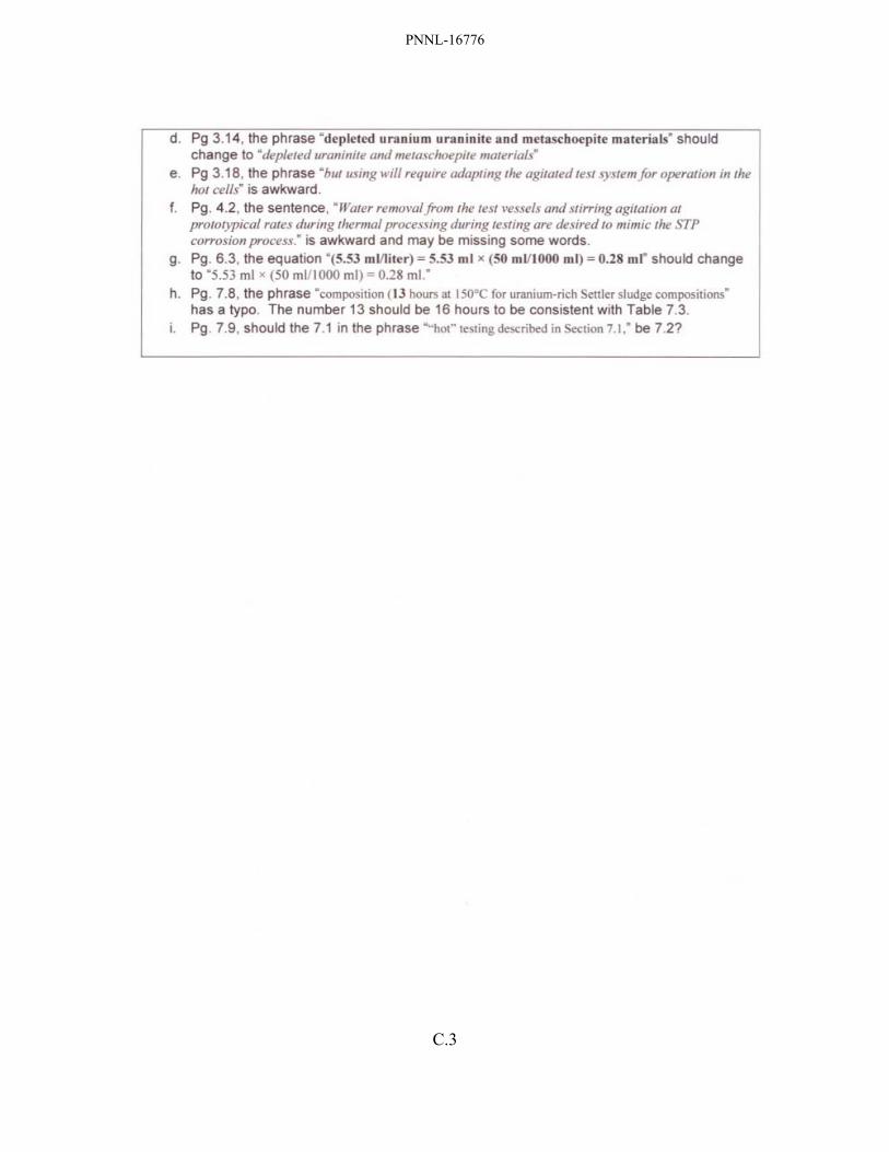
PNNL-16776
C.3

PNNL-16776
D.1
Appendix D
Technical Reviewer Comments – RB Baker, Fluor Hanford
Comments on draft STP Follow-on test plan dated June 2007. Ron Baker July 11, 2007 General comments or questions
1. Page x, Table S.1, entry for SCS-CON-220 sludge for % uranium: The value given for minimum of the range provided (“~60 to 70 wt% U”) seems too high, shouldn’t this be something more like “30% to 70 wt % U”?
2. Page x, Table S.1: The plan deals almost exclusively in “dry” sludge units as opposed to as-settled. Should some consideration of as-settled conditions be considered in some instances? For instance the oxidized uranium metal simulant should be reviewed to see that it is not only chemically like that observed in the sludge but also that its bulk density/percent water is reasonably close to what is observed in the actual sludge. If it varies from the actual sludge it may make a significant in its behavior in the process.
3. Table 3.3. Is it a weakness in the test matrix that, given the primary function of the “STP corrosion process” is the corrosion of uranium metal, none of the follow-on tests actually include any significant known uranium metal corrosion during the testing? Should a conscious question be asked after running/evaluating test Series 1.1 (without added U metal) – are there any apparent potential issues that indicate that uranium metal needs to be a part of the remaining follow-on test?
4. Is it a contradiction that blow sand is indicated as an inert additive and at the same time an active source of Si? For example…Page 3.16 “…As shown by interpretation of the mineral stability fields in Figure 3.8, slaked lime, Ca(OH)2, could be added to the sludge with perhaps some active source of silica (e.g., blow sand) if silica concentrations are too low in the sludge itself to convert the metaschoepite to uranophane”.
5. Does there need to be any kind of verification that “optimization methods” being proposed that include adding new materials to the sludge (at a new lower baseline temperatures) do not have an unanticipated negative impact on the primary objective of the processing (e.g., potentially slowing the reaction of uranium metal at temperature resulting in incomplete elimination of the U metal in the revised process)?
6. Page 7.2, “Two of the KE canister sludges, 96-08 and 96-11, have lower uranium concentration (40 and 9 wt%, respectively, though 96-08 was taken from an empty canister and thus is more representative of floor sludge).”: --- Sample 96-11 was from empty canister, 96-08 was canister fully loaded with fuel (see HNF-SP-1201, Table 3.1).
7. Page 7.6, “Alternative and additional sludge resources may be necessary for the static Test Series 3.4. One potential source of Container sludge is KE Floc Comp. Additional sources of Settler sludge include KC-1 M500, 96-05, and 96-13, all KE canister sludges.” In a number of places through the text (including Figure 7.2), it is indicated or titled that “Container” or “Settler” sludge is being used, when in fact the material being used is targeted in-stand combinations of sub-samples from source sub-streams for Settler and Containers. If it isn’t already clearly noted somewhere, there needs to be a warning for the less informed reader that these are actually not direct “Settler” nor “Container” sludge samples (except in the future case of SCS-CON-220) and that equivalents are used.
8. Did not see any discussions on test duplicates being considered in this test plan. If there are no duplicates, suggest at least one sentence be added somewhere that duplicates are judged not required given the sample/cost/risk benefit involved at this basic phenomena testing level being pursued.
Editorial
9. Page ix: Figure S.1, open hex to the right following Test 3.3 boxes: --- At this point in the discussion it is unclear to the reader what “Optimum Case” means.
10. Page x, Table S.1 (and to some degree elsewhere in text): --- For the general reader there needs to be a footnote or a note in the acronym list or some minor discussion somewhere to indicate that the nomenclature used throughout such as “KC-4” etc. refers to specific K Basin sludge sample identifications.

PNNL-16776
D.2
11. Potential additions to acronym list: DU, IWTS, ROD, STP1 data, KC-4 (etc.), OD, and ID. 12. Page 1.1, “By project definition, K Basin sludge is defined as any particulate material that can pass through
a screen with 0.25-inch openings.” A reference to the sludge databook should be added after this sentence. 13. Figure 3.1 thru 3.5, etc, plus figure S.1: These figures need to be updated to indicate process temperature
150oC instead of 155oC. 14. Figure 3.3, bottom left-hand box: --- should this be test series “3.4” instead of “3.5”? 15. Page 3.4, “An overview of Test Series 1, 2, 3, and 4 and their interconnecting logic (Figure 3.4) outlines the
sequence of testing and testing decision points.” Figure 3.4 should be Figure 3.5. 16. Page 3.6, “As shown in Figure 3.5, the testing will be performed using both K Basin sludge samples (so-
called “hot” tests) and simulated sludge materials (“warm” and “cold” tests).” Suggest insertion of bolded words.
17. Page 3.6, “Limits on the quantity and variety of K Basin sludge samples in the laboratory but primarily the need to perform parametric testing to investigate the effects of sludge composition, dilution, pH (and other chemical process modifications), and temperature; were judged to require the use of simulated sludges in this test program.” Suggest insertion of bolded words.
18. Page 4.1, “The small-scale static testing in Test Series 1.1, 2.1, 2.2, 2.3, 3.2, 3.3, and 3.5 will be conducted…” There is no “3.5” test; was this supposed to be 3.4?
19. Page 4.2, “To allow for gas generation and for expansion of the solid and water phases, the maximum planned sample volume in each 128 ml Parr vessel is 66% of 128 ml, or 85 ml, without added uranium metal or 64 ml without uranium metal.” Second “without” should be “with”.
20. Page 7.6, “The first four tests listed in Table 6.1 (Test Series 1.1) are designed to determine the effects on product strength and other qualities of:” Is the indicated Table 6.1 supposed to be Table 7.2; Table 6.1 does not list tests?
21. Page 7.8, “The effects of process temperature (Test Series 3.4) will be studied as shown in Table 7.4.” Table 7.4 does not appear to have this info.

PNNL-16776
E.1
Appendix E
Resolution of Reviewer Comments Comments to the June 27 version of the draft Test Plan were invited from independent reviewers John Abrefah of PNNL and Ron Baker of Fluor Hanford. As requested, comments were provided and these are shown, respectively, in Appendices C and D. The dispositions of the comments in this final version of the Test Plan are summarized in this Appendix. Most of the comments and specifics provided by John Abrefah were addressed directly, with some exceptions and qualifications, as shown in Table E.1.
Table E.1. Disposition of Comments from John Abrefah Comments / Specifics Resolution
The Test Plan as whole is very well thought of and provides limited comprehensive but adequate testing activities that will generate information to support the Sludge Treatment Project (STP) process. The generated chemical reactions data will provide better understanding of the chemical behavior of the treated K-Basin sludge types to determine the STP processing parameters.
None.
One main issue driving the testing is the loss-of agitation event but the Test Plan failed to enlist a test that will at least evaluate a processing scenario when the agitator stops. There is the general observation that the resolution/reprecipitation of the constituent oxyhydroxides in the sludge is affecting the hardening of the treated sludge. Given that the stirring could enhance the kinetics of the re-solution, the failure of the agitator for a period of time could also influence the final treated sludge product.
Agitator stop/start testing added.
The statement “Favorable outcomes from static testing of actual sludge may obviate the need for the much more complex stirred tests with actual sludge” on pg. vii should be softened to take into account the loss of the agitation event.
Wording changed.
I had a tough time believing the logic for needing all the “cold” tests outlined in the plan. Also for these cold tests to be used in conclusions to guide the subsequent testing, I suggest the addition of small concentration of surrogate material like Ce oxide to replace U oxide effects in the behavior of the simulated sludge.
No defense of this extent of testing is offered beyond the rationales already presented in the draft Test Plan. The suggestion that CeO2 be used as a uranium oxide surrogate was addressed within the text by noting that an adequate surrogate for metaschoepite does not exist and that although CeO2 could be used as a UO2 surrogate, UO2 is chemically non-reactive in the STP process. Therefore, in the interest of simplicity, CeO2 is not included in the “cold” test simulants.
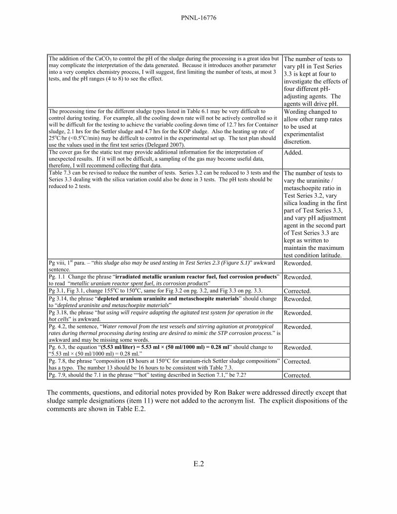
PNNL-16776
E.2
The addition of the CaCO3 to control the pH of the sludge during the processing is a great idea but may complicate the interpretation of the data generated. Because it introduces another parameter into a very complex chemistry process, I will suggest, first limiting the number of tests, at most 3 tests, and the pH ranges (4 to 8) to see the effect.
The number of tests to vary pH in Test Series 3.3 is kept at four to investigate the effects of four different pH-adjusting agents. The agents will drive pH.
The processing time for the different sludge types listed in Table 6.1 may be very difficult to control during testing. For example, all the cooling down rate will not be actively controlled so it will be difficult for the testing to achieve the variable cooling down time of 12.7 hrs for Container sludge, 2.1 hrs for the Settler sludge and 4.7 hrs for the KOP sludge. Also the heating up rate of 25oC/hr (<0.5oC/min) may be difficult to control in the experimental set up. The test plan should use the values used in the first test series (Delegard 2007).
Wording changed to allow other ramp rates to be used at experimentalist discretion.
The cover gas for the static test may provide additional information for the interpretation of unexpected results. If it will not be difficult, a sampling of the gas may become useful data, therefore, I will recommend collecting that data.
Added.
Table 7.3 can be revised to reduce the number of tests. Series 3.2 can be reduced to 3 tests and the Series 3.3 dealing with the silica variation could also be done in 3 tests. The pH tests should be reduced to 2 tests.
The number of tests to vary the uraninite / metaschoepite ratio in Test Series 3.2, vary silica loading in the first part of Test Series 3.3, and vary pH adjustment agent in the second part of Test Series 3.3 are kept as written to maintain the maximum test condition latitude.
Pg viii, 1st para. – “this sludge also may be used testing in Test Series 2.3 (Figure S.1)” awkward sentence.
Reworded.
Pg. 1.1 Change the phrase “irradiated metallic uranium reactor fuel, fuel corrosion products” to read “metallic uranium reactor spent fuel, its corrosion products”
Reworded.
Pg 3.1, Fig 3.1, change 155oC to 150oC, same for Fig 3.2 on pg. 3.2, and Fig 3.3 on pg. 3.3. Corrected. Pg 3.14, the phrase “depleted uranium uraninite and metaschoepite materials” should change to “depleted uraninite and metaschoepite materials”
Reworded.
Pg 3.18, the phrase “but using will require adapting the agitated test system for operation in the hot cells” is awkward.
Reworded.
Pg. 4.2, the sentence, “Water removal from the test vessels and stirring agitation at prototypical rates during thermal processing during testing are desired to mimic the STP corrosion process.” is awkward and may be missing some words.
Reworded.
Pg. 6.3, the equation “(5.53 ml/liter) = 5.53 ml × (50 ml/1000 ml) = 0.28 ml” should change to “5.53 ml × (50 ml/1000 ml) = 0.28 ml.”
Reworded.
Pg. 7.8, the phrase “composition (13 hours at 150°C for uranium-rich Settler sludge compositions” has a typo. The number 13 should be 16 hours to be consistent with Table 7.3.
Corrected.
Pg. 7.9, should the 7.1 in the phrase ““hot” testing described in Section 7.1,” be 7.2? Corrected. The comments, questions, and editorial notes provided by Ron Baker were addressed directly except that sludge sample designations (item 11) were not added to the acronym list. The explicit dispositions of the comments are shown in Table E.2.

PNNL-16776
E.3
Table E.2. Disposition of Comments from Ron Baker Comments / Questions / Editorial Notes Resolution
Page x, Table S.1, entry for SCS-CON-220 sludge for % uranium: The value given for minimum of the range provided (“~60 to 70 wt% U”) seems too high, shouldn’t this be something more like “30% to 70 wt % U”?
Estimated values revised: ~30% used in Table S.1 and comparable Table 3.3.
Page x, Table S.1: The plan deals almost exclusively in “dry” sludge units as opposed to as-settled. Should some consideration of as-settled conditions be considered in some instances? For instance the oxidized uranium metal simulant should be reviewed to see that it is not only chemically like that observed in the sludge but also that its bulk density/percent water is reasonably close to what is observed in the actual sludge. If it varies from the actual sludge it may make a significant in its behavior in the process.
Footnote addressing this concern added to Table S.1 and comparable Table 3.3.
Table 3.3. Is it a weakness in the test matrix that, given the primary function of the “STP corrosion process” is the corrosion of uranium metal, none of the follow-on tests actually include any significant known uranium metal corrosion during the testing? Should a conscious question be asked after running/evaluating test Series 1.1 (without added U metal) – are there any apparent potential issues that indicate that uranium metal needs to be a part of the remaining follow-on test?
Test with uranium metal added to Test Series 3.3 and associated changes made throughout document.
Is it a contradiction that blow sand is indicated as an inert additive and at the same time an active source of Si? For example…Page 3.16 “…As shown by interpretation of the mineral stability fields in Figure 3.8, slaked lime, Ca(OH)2, could be added to the sludge with perhaps some active source of silica (e.g., blow sand) if silica concentrations are too low in the sludge itself to convert the metaschoepite to uranophane”.
Clarification of active silica (from basalt-bearing blow sand) versus inert silica (in quartz sand) sources made in Section 3.4.
Does there need to be any kind of verification that “optimization methods” being proposed that include adding new materials to the sludge (at a new lower baseline temperatures) do not have an unanticipated negative impact on the primary objective of the processing (e.g., potentially slowing the reaction of uranium metal at temperature resulting in incomplete elimination of the U metal in the revised process)?
Test with uranium metal added to Test Series 3.3 to determine these effects.
Page 7.2, “Two of the KE canister sludges, 96-08 and 96-11, have lower uranium concentration (40 and 9 wt%, respectively, though 96-08 was taken from an empty canister and thus is more representative of floor sludge).”: --- Sample 96-11 was from empty canister, 96-08 was canister fully loaded with fuel (see HNF-SP-1201, Table 3.1).
Correction made.
Page 7.6, “Alternative and additional sludge resources may be necessary for the static Test Series 3.4. One potential source of Container sludge is KE Floc Comp. Additional sources of Settler sludge include KC-1 M500, 96-05, and 96-13, all KE canister sludges.” In a number of places through the text (including Figure 7.2), it is indicated or titled that “Container” or “Settler” sludge is being used, when in fact the material being used is targeted in-stand combinations of sub-samples from source sub-streams for Settler and Containers. If it isn’t already clearly noted somewhere, there needs to be a warning for the less informed reader that these are actually not direct “Settler” nor “Container” sludge samples (except in the future case of SCS-CON-220) and that equivalents.
Additional clarification made in discussion in Section 7.
Did not see any discussions on test duplicates being considered in this test plan. If there are no duplicates, suggest at least one sentence be added somewhere that duplicates are judged not required given the sample/cost/risk benefit involved at this basic phenomena testing level being pursued are used.
Rationale for lack of duplicates (test objective is in finding trends) noted in Section 6.
Page ix: Figure S.1, open hex to the right following Test 3.3 boxes: --- At this point in the discussion it is unclear to the reader what “Optimum Case” means.
Words “optimum case” removed in Figures S.1 and comparable Figure 3.3.
Page x, Table S.1 (and to some degree elsewhere in text): --- For the general reader there needs to be a footnote or a note in the acronym list or some minor discussion somewhere to indicate that the nomenclature used throughout such as “KC-4” etc. refers to specific K Basin sludge sample identifications.
Footnote to table added.
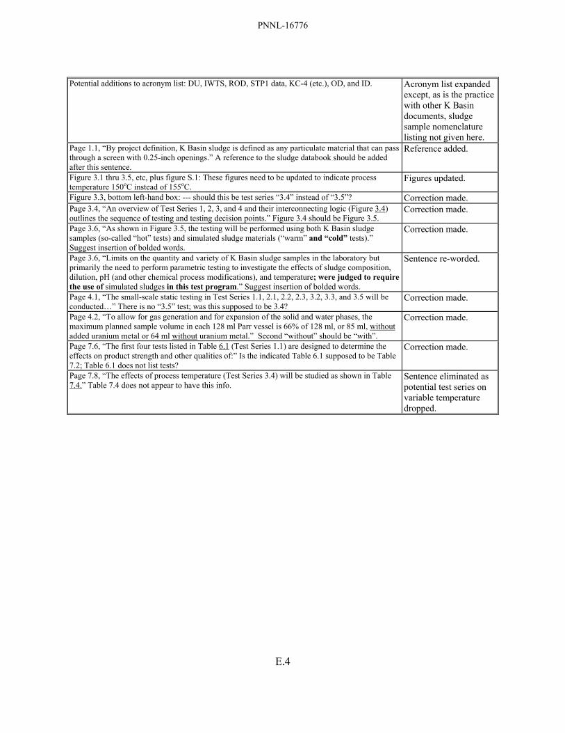
PNNL-16776
E.4
Potential additions to acronym list: DU, IWTS, ROD, STP1 data, KC-4 (etc.), OD, and ID. Acronym list expanded
except, as is the practice with other K Basin documents, sludge sample nomenclature listing not given here.
Page 1.1, “By project definition, K Basin sludge is defined as any particulate material that can pass through a screen with 0.25-inch openings.” A reference to the sludge databook should be added after this sentence.
Reference added.
Figure 3.1 thru 3.5, etc, plus figure S.1: These figures need to be updated to indicate process temperature 150oC instead of 155oC.
Figures updated.
Figure 3.3, bottom left-hand box: --- should this be test series “3.4” instead of “3.5”? Correction made. Page 3.4, “An overview of Test Series 1, 2, 3, and 4 and their interconnecting logic (Figure 3.4) outlines the sequence of testing and testing decision points.” Figure 3.4 should be Figure 3.5.
Correction made.
Page 3.6, “As shown in Figure 3.5, the testing will be performed using both K Basin sludge samples (so-called “hot” tests) and simulated sludge materials (“warm” and “cold” tests).” Suggest insertion of bolded words.
Correction made.
Page 3.6, “Limits on the quantity and variety of K Basin sludge samples in the laboratory but primarily the need to perform parametric testing to investigate the effects of sludge composition, dilution, pH (and other chemical process modifications), and temperature; were judged to require the use of simulated sludges in this test program.” Suggest insertion of bolded words.
Sentence re-worded.
Page 4.1, “The small-scale static testing in Test Series 1.1, 2.1, 2.2, 2.3, 3.2, 3.3, and 3.5 will be conducted…” There is no “3.5” test; was this supposed to be 3.4?
Correction made.
Page 4.2, “To allow for gas generation and for expansion of the solid and water phases, the maximum planned sample volume in each 128 ml Parr vessel is 66% of 128 ml, or 85 ml, without added uranium metal or 64 ml without uranium metal.” Second “without” should be “with”.
Correction made.
Page 7.6, “The first four tests listed in Table 6.1 (Test Series 1.1) are designed to determine the effects on product strength and other qualities of:” Is the indicated Table 6.1 supposed to be Table 7.2; Table 6.1 does not list tests?
Correction made.
Page 7.8, “The effects of process temperature (Test Series 3.4) will be studied as shown in Table 7.4.” Table 7.4 does not appear to have this info.
Sentence eliminated as potential test series on variable temperature dropped.