read and follow all instructions “k … · read and follow all instructions 1a) ... collectors...
TRANSCRIPT
READ AND FOLLOW ALL INSTRUCTIONS
1a) K-Star Heater may be installed indoors or outdoors at least 6”from any object. Ensure that the installation allows access for electrical and plumbing connections and that the Thermostat control is conveniently located.
The installation of current leakage collectors should be done as per Figure 01 before permanently positioning Heater.
Heater must be installed after the filter and before the Air Injector or Automatic Chlorinator.
b) A leakage current collector must be installed at the water inlet,and another at the outlet of the unit, and these shall be electrically insulated from the unit. The installation of the collectors shall besuch that all water entering and leaving the unit flows through the two collectors, as shown in Figure 01. The length of the leakage currentcollectors shall be made of a corrosion resistant metal and shall beprovided with a copper lug brazed to the collector body.
Hand tighten only. Do not use high force with a pipe wrench.
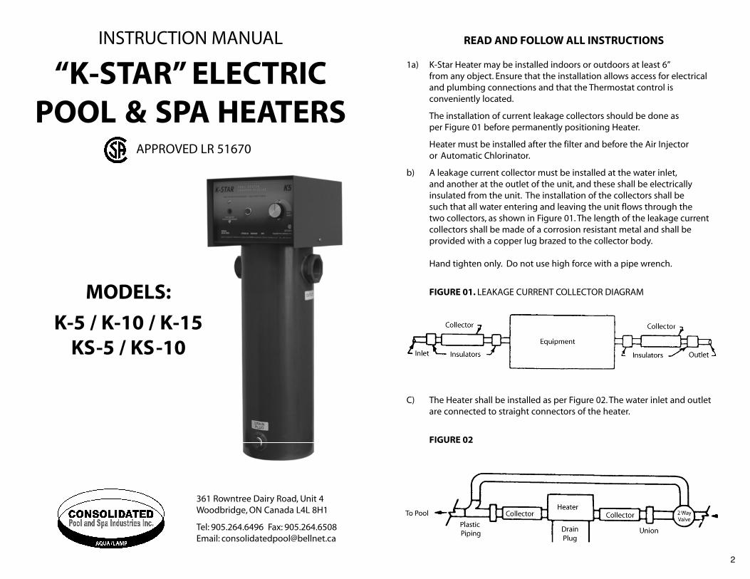
FIGURE 01. LEAKAGE CURRENT COLLECTOR DIAGRAM
C) The Heater shall be installed as per Figure 02. The water inlet and outlet are connected to straight connectors of the heater.
FIGURE 02
2
361 Rowntree Dairy Road, Unit 4 Woodbridge, ON Canada L4L 8H1
Tel: 905.264.6496 Fax: 905.264.6508Email: [email protected]
INSTRUCTION MANUAL
“K-STAR” ELECTRICPOOL & SPA HEATERS
APPROVED LR 51670
MODELS:
K-5 / K-10 / K-15KS-5 / KS-10

2 a) Electrical: Electrical work must be performed by a qualified Electrician and comply with the Canadian Electrical Code or the American National Standard Electrical Code lnforce.
Table 02. The wire sizes to be used are as follows:
For installation see Wiring Schematic figure 03.
FIGURE 03. Wiring Schematic
In Accordance with The Electrical Code in effect
b) A green coloured terminal (or a wire connector marked “C”,“GP”. “Ground”or “Grounding”) is provided within the control box. To reduce the risk of electric shock, connect this terminal or connector to the grounding terminal of the electric service or supply panel with a continuous green insulated copper wire equivalent in size to the circuit conductors
4
Model Amps Fuse(240V G.F.L. Size)
Wire Size(90’ Copper Only)
CollectorGround Wire
(Copper Only)
K-5 & KS-5 21A 30A 10 10
K-10 & KS-10 42A 60A 6 6
K-15 63A 80/100A Use Supply conductorsuitable for 75º C
Use Supply conductorsuitable for 75ºC
3
MECHANICAL INSTALLATION DIAGRAMSHOWING BY PASS
Caution:
i) Do not store chlorine near or in the same room as heater.
ii) Valves must not be installed in the piping on the outlet of heater to the pool.
iii) Use PVC cement for connecting leakage current collectors into tank body and use teflon tape as sealer in the threads for drain plug.
d) Water Flow
The water flow in GPM should not exceed the following limits:
Table 01
Important:
Systems with higher GPM ratings will require a bypass around Heater.This would be necessary if a high velocity pump is employed in the system.
Recommended:
Add water softener for longer heater life.
Heater GPM
K-5 / KS-5 08 (Max)
K-10 / KS-10 10
K-15 10

6
2. Apply electric power to the heater, then rotate the thermostatcontrol clockwise to the max. position.
The red indication lamp will be lit when the heater is on.
3. After the desired temperature is reached, re-adjust the thermostatcontrol to suit your requirement.
The scale ranges from 70 to 110F.
4 A high limit manual reset thermostat is provided as a secondary back up high temperature limit protection. The reset thermostat may trip if the pump is switched off, or the heater chamber has too much air locked in it.To reset, switch the heater breaker off. Allow the heater to cool and then depress the reset, as shown in Figure 05.
Winterizing:
For maximum security, first turn the thermostat to the off position and switchoff the electric power at the circuit breaker.Then completely empty the tank by removing the drain plug located at the bottom of the heater body. Drainplug must be left out all winter. Cover the control panel of the heater with ordinary plastic cover to prevent any penetration of moisture or water intoelectrical components. At all times the unit must be properly ventilated to avoid condensation.
FIGURE 05
WIRING DIAGRAMS (below)
5
supplying this equipment. Addition, bonding lugs are provided and marks“Bonding Lugs”. To reduce the risk of electric shock connect the bonding lugs in accordance with the Canadian Electric Code, Part 1.
c) It is mandatory that all Electrical Pool heaters be installed with Leakage Collectors at the water outlet of filtration system and atthe outlet of heaters.
SAVE THESE INSTRUCTIONS
FIGURE 04
Warning:
Ensure that the unit is properly grounded at the provided lug within the unitand that the leakage collectors are separately grounded at the main entrance.Improper installation may be a potential cause of fire, electric shock, personalinjury or health hazards and great care should be taken to avoid these. Makesure that all wiring is secure.
OPERATING INSTRUCTIONS
1. Must be strictly followed for warranty to be valid.
Before energizing the heater, activate the pump and make sure thatthe air is out of the heater chamber (no air bubbles will enter the pool from the heater). Water circulation must be ensured at all times when unit is energized.

8
WARRANTY(For the Original Owner Only)
K-Star pool heater is guaranteed for a period of one year from the dateof its purchase to the original owner against any manufacturing defects.
Any warranty claim must be pre-authorized by Consolidated Pool & SpaIndustries Inc., and claim must include the serial number, model number,and date of purchase of the unit. Any defective unit shall be returned freightprepaid. Consolidated Pool & Spa Industries Inc., will not be responsible for disconnection-reconnection charges.
The above warranty shall be considered void if:
i) The installation instructions are not followed.ii) Unit is powered without any water circulation.iii) The power is disconnected and unit is not thoroughly drained
at the time of winterizing.iv) The Unit has been mishandled.
Warranty Registration must be done within ten days of the purchase of the unit, by mailing warranty card below to:
(For Warranty Information, Please Mail to Manufacturer)
Customer’s Name
Address
Phone
Unit
Serial #
Model #
Date Purchased
Installer’s Name
361 Rowntree Dairy Road, Unit 4 Woodbridge, ON Canada L4L 8H1
Tel: 905.264.6496 Fax: 905.264.6508Email: [email protected]
7