slope up to min. cover
TRANSCRIPT

CIT
Y O
F H
OLLY
WO
OD
SA
NIT
AR
Y D
ET
AILS
C-503
©
ALERT TO CONTRACTOR:
1. THE PRESENCE OF GROUNDWATER SHOULD BE ANTICIPATED ON THIS PROJECT. CONTRACTOR'S BID
SHALL INCLUDE CONSIDERATION FOR THIS ISSUE. WHEN PERFORMING GRADING OPERATIONS
DURING PERIODS OF WET WEATHER, PROVIDE ADEQUATE DEWATERING, DRAINAGE AND GROUND
WATER MANAGEMENT TO CONTROL MOISTURE OF SOILS. REFER TO MASTER SITE SPECIFICATIONS.
2. ALL WM GENERAL CONTRACTOR WORK TO BE COMPLETED (EARTHWORK, FINAL UTILITIES, AND FINAL
GRADING) BY THE MILESTONE DATE IN PROJECT DOCUMENTS. OUTLOT AREA TO BE KEPT FREE OF
JOB TRAILERS AND STORAGE AFTER THE CONTRACT MILESTONE DATE FOR THE OUTLOT. WM
GENERAL CONTRACTOR TO PROVIDE CLEAR ACCESS FOR OUTLOT CONTRACTOR TO THE SPECIFIC
PARCEL AT ALL TIMES AFTER MILESTONE DATE. PURCHASER OF OUTLOT TO PROVIDE PERMIT
DOCUMENTS AND SWPPP REQUIRED BY STATE/LOCAL REQUIREMENTS FOR SPECIFIC OUTLOT.
THE PRESENCE OF ROCK SHOULD BE ANTICIPATED
ON THIS PROJECT. CONTRACTOR'S BID SHALL
INCLUDE CONSIDERATION FOR ADDRESSING THIS
ISSUE.
TH
E P
LA
CE
A
T
HO
LLY
WO
OD
P
HA
SE
IV
CIT
Y O
F H
OL
LY
WO
OD
DRAWING NO.
REVISED:DATE:
DRAWN:
APPROVED:
EAM
3/01/94
TO EXCEED 12". EACH COMPACTED
2. DENSITY TESTING SHALL BE IN ACCORDANCE WITH AASHTO T-180 AND ASTM D-3017.
(FOR UNSUITABLE
D=DIAMETER
1. BEDDING MATERIAL WHEN NECESSARY, SHALL BE CLEAN SANDY SOIL WHENEVER
AVAILABLE WITHIN THE LIMITS OF CONSTRUCTION. IMPORTED BEDDING SHALL BE
WELL GRADED 3/4" MAX. SIZED CRUSHED LIMEROCK. ALL BEDDING MATERIAL
SHALL BE COMPACTED TO 95% OF MAXIMUM DENSITY BEFORE ANY PIPE IS LAID.
NOTES:
SOIL ONLY)
BEDDING
6"
MIN
.
AND 95% OF MAXIMUM DENSITY
STRUCTURES OR PAVED AREAS
MAXIMUM DENSITY UNDER
EACH COMPACTED TO 100% OF
AREAS AND 95% ELSEWHERE.
UNDER STRUCTURES OR PAVED
BACKFILL IN TWO 6" LAYERS
CAREFULLY PLACED SELECT
TO 100% OF MAXIMUM DENSITY
ELSEWHERE.
TRENCH BOTTOM
FLAT OR RESTORED
TO CENTERLINE OF PIPE
BACKFILL CONSOLIDATED
W=TRENCH WIDTH
12
"
SELECT MATERIAL IN LAYERS NOT
MATCH EXISTING CONDITIONS
SURFACE RESTORATION TO
PIPE O.D. + 2' MAXIMUM
PIPE O.D. + 1' MINIMUM
DRAWING NO.
REVISED:DATE:
DRAWN:
APPROVED:
EAM
3/01/94
OF
P
IP
E
SP
RIN
GL
IN
E
PIP
E Z
ON
E
PIP
E E
MB
ED
ME
NT
MAX. 6"
BEDDING
HAUNCHING
BACKFILL
INITIAL
TO EXCEED 12". EACH COMPACTED
2. DENSITY TESTING SHALL BE IN ACCORDANCE WITH AASHTO T-180 AND ASTM D-3017.
1. BEDDING AND HAUNCHING SHALL BE WELL GRADED 3/4" MAX. SIZE CRUSHED LIMEROCK
NOTES:
AND 95% OF MAXIMUM DENSITY
STRUCTURES OR PAVED AREAS
MAXIMUM DENSITY UNDER
EACH COMPACTED TO 100% OF
AREAS AND 95% ELSEWHERE.
UNDER STRUCTURES OR PAVED
BACKFILL IN TWO 6" LAYERS
CAREFULLY PLACED SELECT
TO 100% OF MAXIMUM DENSITY
ELSEWHERE.
TRENCH BOTTOM
FLAT OR RESTORED
PIPE O.D. + 2' MAXIMUM
6"-1
2"
SELECT MATERIAL IN LAYERS NOT
MATCH EXISTING CONDITIONS
SURFACE RESTORATION TO
PIPE O.D. + 1' MINIMUM
DRAWING NO.
REVISED:DATE:
DRAWN:
APPROVED:
EAM
3/01/94
CENTER A FULL LENGTH OF PIPE
AT THE POINT OF CROSSING
45° OR 22 1/2° BENDS
* REFER TO WATER AND SEWER SEPARATION NOTES PER D.E.R. REQUIREMENTS
RESTRAINED JOINT
CENTER A FULL LENGTH OF PIPE
AT THE POINT OF CROSSING
SLOPE UP TO M
IN. C
OVER
OBSTRUCTION
75% OF MANUFACTURERS
MAX. JOINT DEFLECTION
STANDARD UTILITY CROSSING
NOT TO EXCEED
DEFLECTION TYPE
SPECIAL UTILITY CROSSING
RESTRAINED JOINTS
FITTING TYPE
GRADE
*
MIN
. C
OV
ER
30" F
OR
D
.I.P
.
36" F
OR
P
.V
.C
.
GRADE
OBSTRUCTION
*
* REFER TO WATER AND SEWER SEPARATION NOTES PER D.E.R. REQUIREMENTS
PLAN OF BOTTOM
AND FLOW CURVES
NOTES:
1. INVERT CHANNELS TO BE CONSTRUCTED FOR SMOOTH FLOW WITH NO OBSTRUCTIONS.
2. SPILLWAYS SHALL BE CONSTRUCTED BETWEEN PIPES WITH DIFFERENT INVERT
ELEVATIONS PROVIDING SMOOTH FLOWS.
3. CHANNELS FOR FUTURE CONNECTIONS (STUBS) SHALL BE CONSTRUCTED FILLED
WITH SAND & COVERED WITH 1" OF MORTAR.
4. WHEN FLOW LINE DEFLECTS MORE THAN 45°, A DROP OF 0.10' IS REQUIRED.
DRAWING NO.
REVISED:DATE:
DRAWN:
APPROVED:
EAM
3/01/94
TYPICAL SECTION
DRAWING NO.
REVISED:DATE:
DRAWN:
APPROVED:
EAM
3/01/94
SLOPE
1"/FT.
SEWER PIPE (TYP)
MANHOLE BASE
MANHOLE WALL
(PRECAST CONC.)
CHANNEL IN GROUT
FORM SMOOTH
(FOR PVC ONLY)
MANHOLE COUPLING
ASBESTOS-CEMENT
PROVIDE SMOOTH CHANNEL BETWEEN
PIPES W/DIFFERENT INVERT ELEV.
(WHERE DIFFERENCE EXCEEDS 2',
USE DROP MANHOLE)
MAXIMUM RADIUS
(WHERE APPLICABLE)
6'-4" DIA.
4'-0" DIA. 8"
2'-0" MIN.
1"
6"
8"
VA
RIE
S
FINISHED PAVEMENT
FINISHED GRADE
FRAME AND COVER
MARKED "SANITARY SEWER"
U.S. FOUNDRY TYPE 485-C-ORS
BRICK & MORTAR
BY CONTRACTOR
(3 COURSES MIN.
4 COURSES MAX.)
2 COATS OF
KOPPERS
300-M, O.A.E.
1 COAT
KOPPERS
300-M, O.A.E.
BRICK/RUBBLE
MANHOLE ADAPTER
WITH GROUT
PLAN
SECTION
TO THE CITY PRIOR TO INSTALLATION.
ALL DIMENSIONS AND CALCULATIONS, INCLUDING CONCRETE REINFORCEMENT, SHALL BE SUBMITTED
1. SHOP DRAWINGS, SIGNED AND SEALED BY A FLORIDA REGISTERED PROFESSIONAL ENGINEER, SHOWING
NOTES:
OR APPROVED EQUAL
2. THE BOTTOM SLAB SHALL BE CAST MONOLITHICALLY WITH THE LOWER WALL SECTION.
RAM NECK SEAL
OR APPROVED EQUAL
EAM DRAWING NO.
REVISED:DATE:
DRAWN:
APPROVED:
3/01/94
25"
2"
9"
1"
3 3
/4
"
"A""A"
2"
PLAN
22 3/4"
20 3/4"
COVER SECTION "A-A"
36"
NOTES:
FRAME SECTION "A-A"
2. ALL BEARING SURFACES TO BE MACHINED.
3. MINIMUM WEIGHTS: COVER - 160 LBS., TOTAL - 400 LBS.
1. LETTERS ON COVER TO BE 3/8" HIGH, 1/4" TO 5/16" THICK AND FLUSH WITH TOP OF COVER.
DRAWING NO.
REVISED:DATE:
DRAWN:
APPROVED:
EAM
SECTION
EXISTING MANHOLE
FRAME & COVER
FINISHED GRADE
FINISHED PAVEMENT
EXISTING
CONNECTIONNEW
CONNECTION
2'-0
"
MA
X.
CONSTRUCT SMOOTH
ENTRANCE BY CORE
DRILLING ONLY
FLOW CHANNEL
3/01/94
MANHOLE ADAPTER
FINISHED PAVEMENT
FRAME AND COVER
FINISHED GRADE
MARKED "SANITARY SEWER"
U.S. FOUNDRY TYPE 485-C-ORS
OR APPROVED EQUAL
2. THE BOTTOM SLAB SHALL BE CAST MONOLITHICALLY WITH THE LOWER WALL SECTION.
TO THE CITY PRIOR TO INSTALLATION.
3. ALL PIPE WORK SHALL BE CLASS 50 D.I.P., ENCASED FITTINGS SHALL BE CLASS 350.
1. SHOP DRAWINGS, SIGNED AND SEALED BY A FLORIDA REGISTERED PROFESSIONAL ENGINEER, SHOWING
ALL DIMENSIONS AND CALCULATIONS, INCLUDING CONCRETE REINFORCEMENT, SHALL BE SUBMITTED
RAM NECK SEAL
OR APPROVED EQUAL
NOTES:
90° BEND
LINE
DROP
MIN.
6"
VA
RIE
S
4"
CONCRETE ENCASEMENT
PIPE SPRINGLINE
BRICK DAM TO
DR
OP
GROUTED IN PLACE
TEE
BRICK DAM
4"
4"
SEWER PIPE (TYP)
PLAN
1 COAT KOPPERS
300-M, O.A.E.
2'-0" MIN.
MANHOLE BASE
CHANNEL IN GROUT
MANHOLE WALL
(PRECAST CONC.)
FORM SMOOTH
1"
BRICK & MORTAR
BY CONTRACTOR
(3 COURSES MIN.
4 COURSES MAX.)
8" 4'-0" DIA.
SECTION
6"
WITH GROUT
BRICK/RUBBLE
DRAWING NO.
DATE:
DRAWN:
APPROVED:
EAM
3/01/94

CIT
Y O
F H
OLLY
WO
OD
SA
NIT
AR
Y D
ET
AILS
C-504
©
ALERT TO CONTRACTOR:
1. THE PRESENCE OF GROUNDWATER SHOULD BE ANTICIPATED ON THIS PROJECT. CONTRACTOR'S BID
SHALL INCLUDE CONSIDERATION FOR THIS ISSUE. WHEN PERFORMING GRADING OPERATIONS
DURING PERIODS OF WET WEATHER, PROVIDE ADEQUATE DEWATERING, DRAINAGE AND GROUND
WATER MANAGEMENT TO CONTROL MOISTURE OF SOILS. REFER TO MASTER SITE SPECIFICATIONS.
2. ALL WM GENERAL CONTRACTOR WORK TO BE COMPLETED (EARTHWORK, FINAL UTILITIES, AND FINAL
GRADING) BY THE MILESTONE DATE IN PROJECT DOCUMENTS. OUTLOT AREA TO BE KEPT FREE OF
JOB TRAILERS AND STORAGE AFTER THE CONTRACT MILESTONE DATE FOR THE OUTLOT. WM
GENERAL CONTRACTOR TO PROVIDE CLEAR ACCESS FOR OUTLOT CONTRACTOR TO THE SPECIFIC
PARCEL AT ALL TIMES AFTER MILESTONE DATE. PURCHASER OF OUTLOT TO PROVIDE PERMIT
DOCUMENTS AND SWPPP REQUIRED BY STATE/LOCAL REQUIREMENTS FOR SPECIFIC OUTLOT.
THE PRESENCE OF ROCK SHOULD BE ANTICIPATED
ON THIS PROJECT. CONTRACTOR'S BID SHALL
INCLUDE CONSIDERATION FOR ADDRESSING THIS
ISSUE.
TH
E P
LA
CE
A
T
HO
LLY
WO
OD
P
HA
SE
IV
CIT
Y O
F H
OL
LY
WO
OD
EAM
3/01/94
6" SERVICE
6" WYE
PLUG
1/8" P
ER
FT.
SLO
PE
AT
PLUG
6" SERVICE PIPE
30
" M
IN
.
PLAN
ELEVATION
SINGLE SERVICE CONNECTION
FINISH GRADE
EASEMENT LINE OR
DRAWING NO.
REVISED:DATE:
DRAWN:
APPROVED:
EAM DRAWING NO.
REVISED:DATE:
DRAWN:
APPROVED:
EAMDRAWING NO.
REVISED:DATE:
DRAWN:
APPROVED:
EAM
2. USE RISER CONNECTIONS WHERE INVERT OF SEWER IS GREATER THAN 7'-0" DEEP.
1. SINGLE SERVICE CONNECTIONS SHALL USE 6" PIPE AND FITTINGS.
3. WHERE BELL OF WYE AND SPIGOT OF EXISTING MAIN ARE NOT COMPATIBLE, USE
A SECOND FLEXIBLE COUPLING.
NOTES:
ELEVATION
ALTERNATE ADDITIONAL RISE AND BEND WHERE
MIN. 1/8" PER FT.
REQUIRED BY GREATER SEWER DEPTH
PLAN
WYE BRANCH
FLO
W
SLOPE UP TO P
L
WYE BRANCH
FLO
W
NEW SEWER MAIN
ROTATE BEND AS REQUIRED TO ALIGN
SERVICE BRANCH WITH SERVICE PIPE
EXIST. SEWER MAIN
MISSION, FENCO OR EQUAL
FLEXIBLE COUPLING WITH
STAINLESS STEEL BANDS
SEE
NOTE 3
M.J. TAPPING VALVE
6" C.I. RISER EXTENSION
SAW CUT AND MATCH
EXISTING PAVEMENT
ALSO SEE DETAIL OF PRIVATE FORCE MAIN TIE-IN AT PROPERTY LINE.
NOTE:
MAIN
FORCE
TAPPING SLEEVE
IN UNPAVED AREAS ONLY
CONCRETE ALL AROUND
8"
MIN
.
MIN.
6"
6"
MARKED "SEWER"
C.I. VALVE RISER AND COVER
FINISHED GRADE
OR PAVEMENT
3/01/94 3/01/943/01/94
4"
FLUSH BRASS
SCREW PLUG
CONCRETE
COLLAR
1 #3 CONT.
CISP CLEANOUT
EXTENSION
AS REQUIRED
18" SQUARE
FLUSH BRASS
SCREW PLUG
ASPHALT
SURFACE
LIMEROCK
BASE
CISP CLEANOUT
EXTENSION
AS REQUIRED
CONCRETE
SLAB
YARD TYPE
PAVEMENT TYPE
6" RISER
6" WYE
6" RESIDENTIAL SERVICE
(BY OTHERS)
PROPERTY LINE
PIPE
CLEANOUT DETAILS
EX
TE
NS
IO
N IF
R
EQ
UIR
ED
OP
ER
AT
IN
G N
UT
T
O B
E
WIT
HIN
2
4" O
F F
IN
IS
H
GR
AD
E - IN
ST
AL
L
EAM
3/01/94
DRAWING NO.
REVISED:DATE:
DRAWN:
APPROVED:
EAM
3/01/94
DRAWING NO.
REVISED:DATE:
DRAWN:
APPROVED:
EAM
3/01/94
VA
LV
E B
OX
FIN
IS
H G
RA
DE
24
" C
ON
CR
ET
E P
AD
B
12"
MIN.
2B
CO
NC
RE
TE
T
HR
US
T B
LO
CK
8"
A
A +
4
"
LE
AV
E B
OL
TS
E
XP
OS
ED
NO
TE
:
AL
L C
ON
CR
ET
E T
O B
E 3
00
0 P
.S
.I.
A
1. THE AREAS IN THE TABLE ARE BASED ON _____ POUNDS PER SQUARE FOOT SOIL
BEARING AGAINST THE UNDISTURBED TRENCH WALL AND ARE TO REPRESENT THE MINIMUM
VERTICAL PROJECTED AREA AT THE THRUST BLOCK IN A PLANE PERPENDICULAR TO THE
2. POUR THRUST BLOCKS AGAINST UNDISTURBED MATERIAL. WHERE TRENCH WALL HAS BEEN
DISTURBED, EVACUATE LOOSE MATERIAL AND EXTEND THRUST BLOCK TO UNDISTURBED MATERIAL.
LINE BISECTING THE INCLUDING ANGLE OF THE FITTING.
3. ON BENDS AND TEES, EXTEND THRUST BLOCKS FULL LENGTH OF FITTING.
4. DO NOT COVER COUPLING OR JOINTS WITH CONCRETE.
5. CONCRETE TO BE 2500 P.S.I. MINIMUM 28 DAY STRENGTH.
NOTES:
B
BLOCKING
UNDISTURBED MATERIAL (SQ. FT.)
4" OR 6"
MINIMUM CONCRETE THRUST BLOCKING BEARING ON
45° BEND
MARK
B
VISQUEEN
TEE
VISQUEEN
WOOD
A
90° BEND
8"
PIPE SIZE
10"
A
VISQUEEN
A
WOOD BLOCKING TYP.
TYPICAL SECTION
12"
CONC. THRUST BLOCK
TEE WITH PLUG
B
VISQUEEN
PLUG
A
TEE WITH PLUG
PLUG
A
A
DRAWING NO.
REVISED:DATE:
DRAWN:
APPROVED:
IN
ST
AL
L E
XT
EN
SIO
N IF
R
EQ
UIR
ED
OP
ER
AT
IN
G N
UT
T
O B
E
WIT
HIN
2
4" O
F F
IN
IS
H G
RA
DE
TYP.
6. TABLE TO BE COMPLETED BY DESIGN ENGINEER.
AN
D V
AL
VE
B
OX
4" F
LA
NG
ED
S
.S
. F
EM
AL
E
6" P
LU
G V
AL
VE
6" F
.M
.
FLO
W
4" P
LU
G V
AL
VE
SE
CT
IO
N A
-A
6"x4
" W
YE
B
RA
NC
H
8"
8"
GR
AD
E
FIN
IS
H
ME
TE
R B
OX
PLA
N
KA
ML
OC
K A
DA
PT
OR
& K
AM
LO
CK
C
AP
"A" "A"
4" 45° BEND
R/W
L
IN
E
R/W
L
IN
E
6" P
RIV
AT
E F
OR
CE
M
AIN
ST
EE
L T
RA
FF
IC
C
OV
ER
10
'x1
0' U
TIL
IT
Y E
AS
EM
EN
T
24
"x1
3" C
ON
C.
8" C
ON
C.
4" 90° BEND
TT
SO
D
SOD
SOD
SOD SOD
SOD
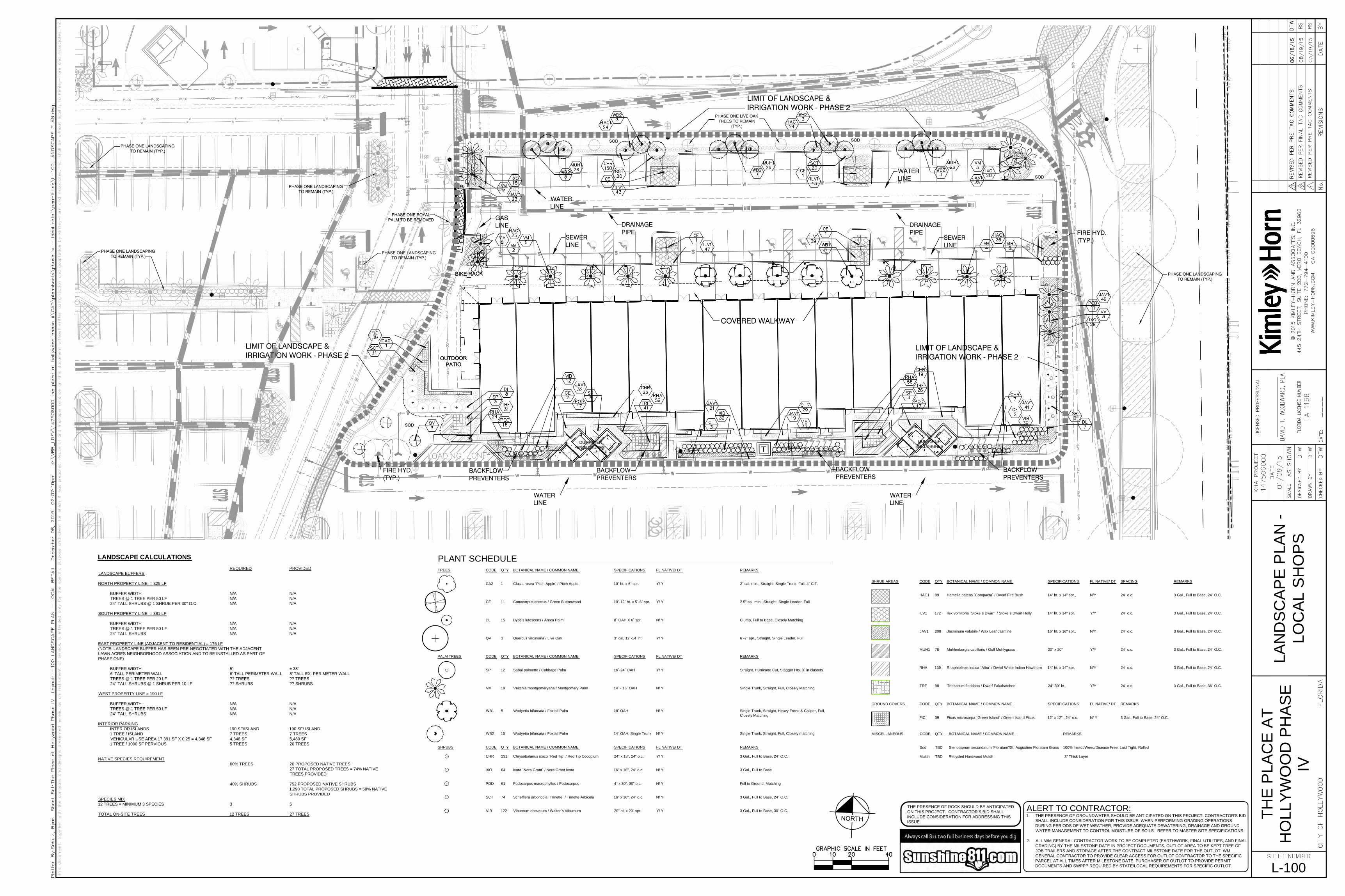
DUMPSTERENCLOSURES
DUMPSTERENCLOSURES
PHASE ONE ROYALPALM TO BE REMOVED
PHASE ONE LIVE OAKTREES TO REMAIN
(TYP.)
PHASE ONE LANDSCAPINGTO REMAIN (TYP.)
PHASE ONE LANDSCAPINGTO REMAIN (TYP.)
PHASE ONE LANDSCAPINGTO REMAIN (TYP.)
PHASE ONE LANDSCAPINGTO REMAIN (TYP.)
FIRE HYD.(TYP.)
LIMIT OF LANDSCAPE &IRRIGATION WORK - PHASE 2
WATERLINE
DRAINAGEPIPE
SEWERLINE
SEWERLINE
DRAINAGEPIPE
WATERLINE
LIMIT OF LANDSCAPE &IRRIGATION WORK - PHASE 2
FIRE HYD.(TYP.)
BACKFLOWPREVENTERS
WATERLINE
BACKFLOWPREVENTERS
BACKFLOWPREVENTERS
BACKFLOWPREVENTERS
WATERLINE
GASLINE
LIMIT OF LANDSCAPE &IRRIGATION WORK - PHASE 2
PHASE ONE LANDSCAPINGTO REMAIN (TYP.)
COVERED WALKWAY
TREES CODE QTY BOTANICAL NAME / COMMON NAME SPECIFICATIONS FL NATIVE/ DT REMARKS
CA2 1 Clusia rosea `Pitch Apple` / Pitch Apple 10` ht. x 6` spr. Y/ Y 2" cal. min., Straight, Single Trunk, Full, 4` C.T.
CE 11 Conocarpus erectus / Green Buttonwood 10`-12` ht. x 5`-6` spr. Y/ Y 2.5" cal. min., Straight, Single Leader, Full
DL 15 Dypsis lutescens / Areca Palm 8` OAH X 6` spr. N/ Y Clump, Full to Base, Closely Matching
QV 3 Quercus virginiana / Live Oak 3" cal, 12`-14` ht Y/ Y 6`-7` spr., Straight, Single Leader, Full
PALM TREES CODE QTY BOTANICAL NAME / COMMON NAME SPECIFICATIONS FL NATIVE/ DT REMARKS
SP 12 Sabal palmetto / Cabbage Palm 16`-24` OAH Y/ Y Straight, Hurricane Cut, Stagger Hts. 3` in clusters
VM 19 Veitchia montgomeryana / Montgomery Palm 14` - 16` OAH N/ Y Single Trunk, Straight, Full, Closely Matching
WB1 5 Wodyetia bifurcata / Foxtail Palm 18` OAH N/ Y Single Trunk, Straight, Heavy Frond & Caliper, Full,
Closely Matching
WB2 15 Wodyetia bifurcata / Foxtail Palm 14` OAH, Single Trunk N/ Y Single Trunk, Straight, Full, Closely matching
SHRUBS CODE QTY BOTANICAL NAME / COMMON NAME SPECIFICATIONS FL NATIVE/ DT REMARKS
CHR 231 Chrysobalanus icaco `Red Tip` / Red Tip Cocoplum 24" x 18", 24" o.c. Y/ Y 3 Gal., Full to Base, 24" O.C.
IXO 64 Ixora `Nora Grant` / Nora Grant Ixora 16" x 16", 24" o.c. N/ Y 3 Gal., Full to Base
POD 61 Podocarpus macrophyllus / Podocarpus 4` x 30", 30" o.c. N/ Y Full to Ground, Matching
SCT 74 Schefflera arboricola `Trinette` / Trinette Arbicola 16" x 16", 24" o.c. N/ Y 3 Gal., Full to Base, 24" O.C.
VIB 122 Viburnum obovatum / Walter`s Viburnum 20" ht. x 20" spr. Y/ Y 3 Gal., Full to Base, 30" O.C.
PLANT SCHEDULE
SHRUB AREAS CODE QTY BOTANICAL NAME / COMMON NAME SPECIFICATIONS FL NATIVE/ DT SPACING REMARKS
HAC1 99 Hamelia patens `Compacta` / Dwarf Fire Bush 14" ht. x 14" spr., N/Y 24" o.c. 3 Gal., Full to Base, 24" O.C.
ILV1 172 Ilex vomitoria `Stoke`s Dwarf` / Stoke`s Dwarf Holly 14" ht. x 14" spr. Y/Y 24" o.c. 3 Gal., Full to Base, 24" O.C.
JAV1 208 Jasminum volubile / Wax Leaf Jasmine 16" ht. x 16" spr., N/Y 24" o.c. 3 Gal., Full to Base, 24" O.C.
MUH1 78 Muhlenbergia capillaris / Gulf Muhlygrass 20" x 20" Y/Y 24" o.c. 3 Gal., Full to Base, 24" O.C.
RHA 139 Rhaphiolepis indica `Alba` / Dwarf White Indian Hawthorn 14" ht. x 14" spr. N/Y 24" o.c. 3 Gal., Full to Base, 24" O.C.
TRF 98 Tripsacum floridana / Dwarf Fakahatchee 24"-30" ht., Y/Y 24" o.c. 3 Gal., Full to Base, 36" O.C.
GROUND COVERS CODE QTY BOTANICAL NAME / COMMON NAME SPECIFICATIONS FL NATIVE/ DT REMARKS
FIC 39 Ficus microcarpa `Green Island` / Green Island Ficus 12" x 12" , 24" o.c. N/ Y 3 Gal., Full to Base, 24" O.C.
MISCELLANEOUS CODE QTY BOTANICAL NAME / COMMON NAME REMARKS
Sod TBD Stenotaprum secundatum 'Floratam'/St. Augustine Floratam Grass 100% Insect/Weed/Disease Free, Laid Tight, Rolled
Mulch TBD Recycled Hardwood Mulch 3" Thick Layer
LA
ND
SC
AP
E P
LA
N -
LO
CA
L S
HO
PS
L-100
©
ALERT TO CONTRACTOR:
1. THE PRESENCE OF GROUNDWATER SHOULD BE ANTICIPATED ON THIS PROJECT. CONTRACTOR'S BID
SHALL INCLUDE CONSIDERATION FOR THIS ISSUE. WHEN PERFORMING GRADING OPERATIONS
DURING PERIODS OF WET WEATHER, PROVIDE ADEQUATE DEWATERING, DRAINAGE AND GROUND
WATER MANAGEMENT TO CONTROL MOISTURE OF SOILS. REFER TO MASTER SITE SPECIFICATIONS.
2. ALL WM GENERAL CONTRACTOR WORK TO BE COMPLETED (EARTHWORK, FINAL UTILITIES, AND FINAL
GRADING) BY THE MILESTONE DATE IN PROJECT DOCUMENTS. OUTLOT AREA TO BE KEPT FREE OF
JOB TRAILERS AND STORAGE AFTER THE CONTRACT MILESTONE DATE FOR THE OUTLOT. WM
GENERAL CONTRACTOR TO PROVIDE CLEAR ACCESS FOR OUTLOT CONTRACTOR TO THE SPECIFIC
PARCEL AT ALL TIMES AFTER MILESTONE DATE. PURCHASER OF OUTLOT TO PROVIDE PERMIT
DOCUMENTS AND SWPPP REQUIRED BY STATE/LOCAL REQUIREMENTS FOR SPECIFIC OUTLOT.
THE PRESENCE OF ROCK SHOULD BE ANTICIPATED
ON THIS PROJECT. CONTRACTOR'S BID SHALL
INCLUDE CONSIDERATION FOR ADDRESSING THIS
ISSUE.
TH
E P
LA
CE
A
T
HO
LLY
WO
OD
P
HA
SE
IV
LANDSCAPE CALCULATIONS
REQUIRED PROVIDED
LANDSCAPE BUFFERS
NORTH PROPERTY LINE = 325 LF
BUFFER WIDTH N/A N/A
TREES @ 1 TREE PER 50 LF N/A N/A
24" TALL SHRUBS @ 1 SHRUB PER 30" O.C. N/A N/A
SOUTH PROPERTY LINE = 381 LF
BUFFER WIDTH N/A N/A
TREES @ 1 TREE PER 50 LF N/A N/A
24" TALL SHRUBS N/A N/A
EAST PROPERTY LINE (ADJACENT TO RESIDENTIAL) = 176 LF
(NOTE: LANDSCAPE BUFFER HAS BEEN PRE-NEGOTIATED WITH THE ADJACENT
LAWN ACRES NEIGHBORHOOD ASSOCIATION AND TO BE INSTALLED AS PART OF
PHASE ONE)
BUFFER WIDTH 5' ± 38'
6' TALL PERIMETER WALL 6' TALL PERIMETER WALL 8' TALL EX. PERIMETER WALL
TREES @ 1 TREE PER 20 LF ?? TREES ?? TREES
24" TALL SHRUBS @ 1 SHRUB PER 10 LF ?? SHRUBS ?? SHRUBS
WEST PROPERTY LINE = 190 LF
BUFFER WIDTH N/A N/A
TREES @ 1 TREE PER 50 LF N/A N/A
24" TALL SHRUBS N/A N/A
INTERIOR PARKING
INTERIOR ISLANDS 190 SF/ISLAND 190 SF/ ISLAND
1 TREE / ISLAND 7 TREES 7 TREES
VEHICULAR USE AREA 17,391 SF X 0.25 = 4,348 SF 4,348 SF 5,480 SF
1 TREE / 1000 SF PERVIOUS 5 TREES 20 TREES
NATIVE SPECIES REQUIREMENT
60% TREES 20 PROPOSED NATIVE TREES
27 TOTAL PROPOSED TREES = 74% NATIVE
TREES PROVIDED
40% SHRUBS 752 PROPOSED NATIVE SHRUBS
1,298 TOTAL PROPOSED SHRUBS = 58% NATIVE
SHRUBS PROVIDED
SPECIES MIX
12 TREES = MINIMUM 3 SPECIES 3 5
TOTAL ON-SITE TREES 12 TREES 27 TREES

LA
ND
SC
AP
E
SP
EC
IF
IC
AT
IO
NS
&
PLA
NT
IN
G D
ET
AILS
L-101
©
ALERT TO CONTRACTOR:
1. THE PRESENCE OF GROUNDWATER SHOULD BE ANTICIPATED ON THIS PROJECT. CONTRACTOR'S BID
SHALL INCLUDE CONSIDERATION FOR THIS ISSUE. WHEN PERFORMING GRADING OPERATIONS
DURING PERIODS OF WET WEATHER, PROVIDE ADEQUATE DEWATERING, DRAINAGE AND GROUND
WATER MANAGEMENT TO CONTROL MOISTURE OF SOILS. REFER TO MASTER SITE SPECIFICATIONS.
2. ALL WM GENERAL CONTRACTOR WORK TO BE COMPLETED (EARTHWORK, FINAL UTILITIES, AND FINAL
GRADING) BY THE MILESTONE DATE IN PROJECT DOCUMENTS. OUTLOT AREA TO BE KEPT FREE OF
JOB TRAILERS AND STORAGE AFTER THE CONTRACT MILESTONE DATE FOR THE OUTLOT. WM
GENERAL CONTRACTOR TO PROVIDE CLEAR ACCESS FOR OUTLOT CONTRACTOR TO THE SPECIFIC
PARCEL AT ALL TIMES AFTER MILESTONE DATE. PURCHASER OF OUTLOT TO PROVIDE PERMIT
DOCUMENTS AND SWPPP REQUIRED BY STATE/LOCAL REQUIREMENTS FOR SPECIFIC OUTLOT.
THE PRESENCE OF ROCK SHOULD BE ANTICIPATED
ON THIS PROJECT. CONTRACTOR'S BID SHALL
INCLUDE CONSIDERATION FOR ADDRESSING THIS
ISSUE.
TH
E P
LA
CE
A
T
HO
LLY
WO
OD
P
HA
SE
IV
8. 3" MINIMUM OF MULCH
AS SPECIFIED ON PLANT
SCHEDULE
STARTING 3" FROM TRUNK.
GRAY WOOD
(MEASURED TO
TOP OF HARDENED
TRUNK)
CLEAR WOOD
(MEASURED TO
BOTTOM OF
LEAF SHEATHS)
OVERALL PALM
HEIGHT (MEASURED
TO TOP OF BUD)
D. CONTRACTOR SHALL
ASSURE PERCOLATION
OF ALL PLANTING
PITS PRIOR TO
INSTALLATION.
C. FINAL TREE STAKING
DETAILS AND PLACE-
MEANT TO BE AP-
PROVED BY OWNER.
B. SEE PLANS AND
SPECS. FOR PALMS W/
BOOTS TO REMAIN ON
TRUNK.
A. WASHINGTONIA
PALMS SIMILAR
W/BOOTS INTACT.
A
C
E
NOTES:
ORANGE COLOR PLASTIC UTILITY
BARRIER BY CONWED PLASTICS.
CALL R.H. MOORE &
ASSOCIATES:
800-330-2333.
3. FILTER CLOTH
6. The work shall be coordinated with other trades to prevent conflicts. Coordinate the
planting with the irrigation work to assure availability of water and proper location of
irrigation items and plants.
Fifty percent (50%) of the nitrogen shall be derived from natural organic sources. The
following fertilizers shall be used and applied at rates as suggested by manufacturer's
specifications:
All plants and planting included under this Contract shall be maintained by watering,
cultivating, spraying, and all other operations (such as re-staking or repairing guy
supports) necessary to insure a healthy condition by the Contractor until Certification of
Acceptability by the Landscape Architect or Owner. Maintenance after the Certification
of Acceptability shall be in accordance with the specifications in this section.
Contractors are requested to provide a bid estimate to cover landscape and irrigation
maintenance for a period of 90 calendar days commencing after acceptance.
Upon completion of all planting work and before final acceptance, the Contractor shall
remove all material, equipment, and debris resulting from his work. All paved areas shall
be broom cleaned and the site left in a neat and acceptable condition as approved by
the Owner's Authorized Representative.
b. Water every day for ten (10) successive days, then water three (3) times per week (at
even intervals) for two (2) additional weeks. All watering shall be of sufficient quantity
to wet or restore water to depth of four (4) inches.
a. Within the contract limits, the Contractor shall produce a dense, well established lawn.
The Contractor shall be responsible for the repair and re-sodding of all eroded, sunken
or bare spots until Certification of Acceptability by the Landscape Architect or Owner.
Repaired sodding shall be accomplished as in the original work (including regrading if
necessary).
5. During delivery, prior to and during the planting of the lawn areas, the sod panels shall
at all times be protected from excessive drying and unnecessary exposure of the roots
to the sun. All sod shall be stacked so as not to be damaged by sweating or excessive
heat and moisture.
c. Sod panels shall be laid tightly together so as to make a solid sodded lawn area.
Sod shall be laid uniformly against the edges of all curbs and other hardscape elements,
paved and planted areas. Adjacent to buildings, a four inch mulch strip shall be
provided. Immediately following sod laying, the lawn areas shall be rolled with a lawn
roller customarily used for such purposes, and then thoroughly irrigated. If, in the opinion
of the Owner, top-dressing is necessary after rolling to fill the voids between the sod
panels and to even out inconsistencies in the sod, clean sand as approved by the
Landscape Architect or Owner shall be uniformly spread over the entire surface of the
sod and thoroughly watered in.
b. The sod shall be certified to meet Florida State Plant Board Specifications, absolutely
true to varietal type, and free from weeds, fungus, insects and disease of any kind.
a. The Contractor shall sod all areas that are not paved or planted as designated on
the drawings within the contract limits, unless specifically noted otherwise.
3. Soil Preparation: Prepare loose bed four (4) inches deep. Apply fertilizer at rate of
twenty (20) pounds per one thousand (1000) square feet. Application shall be uniform,
utilizing approved mechanical spreaders. Mix fertilizer thoroughly with the soil to a
depth of three (3) inches. Hand rake until all bumps and depressions are removed. Wet
prepared area thoroughly.
2. Lawn Bed Preparation: All areas that are to be sodded shall be cleared of any
rough grass, weeds, and debris, and the ground brought to an even grade. The whole
surface shall be rolled with a roller weighing not more than one-hundred (100) pounds
per foot of width. During the rolling, all depressions caused by settlement of rolling
shall be filled with additional soil, and the surface shall be regraded and rolled until
presenting a smooth and even finish that is up to the required grade.
1. The work consists of lawn bed preparation, soil preparation, and sodding complete, in
strict accordance with the specifications and the applicable drawings to produce a
grass lawn acceptable to the Owner.
16. Herbicide Weed Control: All plant beds shall be kept free of noxious weeds until
final acceptance of work. If directed by the Owner, "Round-Up" shall be applied for
weed control by qualified personnel to all planting areas in spot applications per
manufacturer's precautions and specifications. Prior to final inspection, treat all
planting beds with an approved pre-emergent herbicide at an application rate
recommended by the manufacturer.
15. Mulching: Provide a three (3) inch minimum layer of specified mulch over the entire
area of each shrub bed, ground cover and vine bed and tree pit.
14. Tree guying and bracing shall be installed by the Landscape Contractor in
accordance with the plans to insure stability and maintain trees in an upright position. If
the Landscape Contractor and Owner decide to waive the tree guying and bracing, the
Owner shall notify the Landscape Architect in writing of their intentions and agree to hold
harmless the Landscape Architect in the event any trees fall down and damage person or
property.
13. Shrubs and ground cover plants shall be evenly spaced in accordance with the
drawings and as indicated on the Plant List. Cultivate all planting areas to a minimum
depth of 6", remove and dispose all debris. Till into top 4" the planting soil mix as
specified in Section E. Thoroughly water all plants after installation.
12. Pruning: Each tree shall be pruned to preserve the natural character of the plant as
shown on the drawings. All soft wood or sucker growth and all broken or badly damaged
branches shall be removed with a clean cut.
4. 3-2" X 8' LODGE POLES.
NAIL (DRILL AND NAIL IF
NECESSARY) TO BATTENS
2" X 4" STAKES. FLAG AT
MIDPOINT AND AT BASE.
6. FINISHED GRADE
(SEE GRADING PLAN)
1. All container grown material shall be healthy, vigorous, well-rooted plants and
established in the container in which they are sold. The plants shall have tops which are
of good quality and are in a healthy growing condition.
2. Work shall include maintenance and watering of all planting areas of this Contract until
Certification of Acceptability by the Owner.
1. The work consists of furnishing all labor, materials, equipment, tools, transportation,
and any other appurtenances necessary for the completion of this project as shown
on the Drawings, as included in the Plant List, and as herein specified.
5. SOIL BERM TO HOLD WATER.
4. 3" MINIMUM OF LAYER OF
MULCH AS SPECIFIED ON PLANT
SCHEDULE STARTING 3" FROM
TRUNK.
3. THREE 2" X 8' LODGE POLES
SPACE EVENLY AROUND TREE.
2. #10 GAUGE WIRE (NOTE FOR
MULTI-TRUCK TREES, GUY TO
STRONGEST TRUNK AT
CENTER).
1. PROTECT TREE TRUNK WITH
BLACK RUBBER HOSE.
3. FIVE 2" X 4" X 18" WOOD
BATTONS
2. TWO STEEL BANDS TO
SECURE BATTENS
1. 5 LAYERS OF BURLAP
TO PROTECT TRUNK
4. Protection of Palms (if applicable): Only a minimum of fronds shall be removed from
the crown of the palm trees to facilitate moving and handling. Clear Trunk (CT) shall be
as specified after the minimum of fronds have been removed. All palms shall be braced
per detail.
5. Excavation of tree pits shall be done using extreme care to avoid damage to
surface and subsurface elements such as utilities or hardscape elements, footers and
prepared sub- bases.
Commercial fertilizer shall be a complete formula; it shall be uniform in composition, dry
and free flowing. This fertilizer shall be delivered to the site in the original unopened
containers, each bearing the manufacturer's guaranteed statement of analysis.
Water necessary for planting and maintenance shall be of satisfactory quality to sustain
an adequate growth of plants and shall not contain harmful, natural or man-made elements
detrimental to plants. Water meeting the above standard shall be obtained on the site
from the Owner, if available, and the Contractor shall be responsible to make arrangements
for its use by His tanks, hoses, sprinklers, etc. If such water is not available at the site,
the Contractor shall provide such satisfactory water from sources off the site at no
additional cost to the Owner.
Sand shall be coarse, clean, well draining native sand. Contractor shall submit results
of soil tests for topsoil and sand proposed for use under this Contract for approval
by the Owner.
Topsoil for use in preparing soil for backfilling plant pits shall be thirty percent (30%)
muck and seventy percent (70%) sand and be fertile, friable, and of a loamy character,
without mixture of subsoil materials, and obtained from a well-drained, arable site. It
shall contain three (3) to five (5) percent decomposed organic matter and shall be free
from heavy clay, coarse sand, stones, lime, lumps, plants, roots or other foreign materials,
or noxious weeds. It shall not contain toxic substances which may be harmful to plant
growth. pH range shall be 5.0 to 7.0 inclusive.
c. Inspection: Plants shall be subject to inspection and approval at the place of
growth, or upon delivery to the site, as determined by the Owner, for quality, size, and
variety; such approval shall not impair the right of inspection and rejection at the site
during progress of the work or after completion for size and condition of balls or roots,
latent defects or injuries. Rejected plants shall be removed immediately from the site.
Notice requesting inspection shall be submitted in writing by the Contractor at least one
(1) week prior to anticipated date.
a. Plant species and size shall conform to those indicated on the drawings.
Nomenclature shall conform to STANDARDIZED PLANT NAMES, 1942 Edition. All nursery
stock shall be in accordance with GRADES AND STANDARDS FOR NURSERY PLANTS
Parts I and II, latest edition published by the Florida Department of Agriculture and
Consumer Services. All plants shall be Florida Grade No. 1 or better as determined by
the Florida Division of Plant Industry. All plants shall be freshly dug, sound, healthy,
vigorous, well-branched and free of disease and insects, insect eggs and larvae and
shall have adequate root systems. Trees for planting in rows shall be uniform in size and
shape. All materials shall be subject to approval by the Owner. Where any requirements
are omitted from the Plant List, the plants furnished shall be normal for the variety.
Plants shall be pruned prior to delivery only upon the approval of the Owner.
Samples of materials as listed below shall be submitted for approval, on the site or
as otherwise determined by the Owner. Upon approval of samples, delivery of
materials may begin.
The Contractor shall be responsible for all unauthorized cutting or damage to trees
and shrubs existing or otherwise, caused by careless operation of equipment,
stockpiling of materials, etc. This shall include compaction by driving or parking inside
the drip-line or the spilling of oil, gasoline, or other deleterious materials within the
drip-line. No materials shall be burned where the heat will damage any plant. Trees
killed or damaged so that they are misshapen and/ or unsightly shall be replaced at
the cost to the Contractor of One Hundred Dollars ($100) per caliper inch on an
escalating scale which adds an additional twenty (20) per cent per inch over four (4)
inches caliper as fixed and agreed liquidated damages. Caliper shall be measured six
(6) inches above ground level for trees up to and including four (4) inches in caliper
and twelve (12) inches above
ground level for trees over four (4) inches in caliper.
All existing buildings, walks, walls, paving, piping, and other items of construction and
planting already completed or established shall be protected from damage by this
Contractor unless otherwise specified. All damage resulting from negligence shall be
repaired or replaced to the satisfaction of the Owner.
Trees shall be planted in the existing native soil onsite unless determined to be
unsuitable at which point the contractor shall contact Landscape Architect to discuss
alternate recommendation prior to planting.
3. 5 LAYERS OF BURLAP
TO PROTECT TRUNK.
BEST FACE OF SHRUB/
GROUNDCOVER TO FACE
FRONT OF PLANTING BED.
Large Tree Planting Detail
B. FINAL TREE STAKING DETAILS
AND PLACEMENT TO BE
APPROVED BY OWNER.
A.CONTRACTOR SHALL ASSURE
PERCOLATION OF ALL
PLANTING PITS PRIOR TO
INSTALLATION.
10. ROOTBALLS GREATER THAN
24" DIAMETER SHALL BE
PLACED ON MOUND OF
UNDISTURBED SOIL TO
PREVENT SETTLING
ROOTBALLS SMALLER THAN
24" IN DIA. MAY SIT
ON COMPACTED EARTH.
9. PREPARED PLANTING SOIL
AS SPECIFIED.
8. B & B OR CONTAINERIZED
(SEE SPECIFICATIONS FOR
ROOT BALL REQUIREMENTS).
7. TOP OF ROOTBALL MIN. 1"
ABOVE FINISHED GRADE
2. PRUNE AND TIE FRONDS WITH
HEMP TWINE. CABBAGE PALMS
TO BE "HURRICANE CUT"
1. MINIMUM OF NINE (9)
GOOD PALM FRONDS
C. "TREE SAVER"
ANCHORING SYSTEM MAY BE
SUBSTITUTED FOR WOOD
STAKING SYSTEM UPON
APPROVAL BY OWNER OR
LANDSCAPE ARCHITECT
(Less Than 14') NTS
SECTION
Small Tree Planting Detail
SECTION
B
A. CONTRACTOR SHALL ASSURE
PERCOLATION OF ALL PLANTING
PITS PRIOR TO INSTALLATION.
12. ROOTBALLS GREATER THAN
24" DIAMETER SHALL BE
PLACED ON MOUND OF
UNDISTURBED SOIL TO
PREVENT SETTLING.
11. PREPARED PLANTING SOIL
AS SPECIFIED.
10. 2" x 4" x 3' (MIN), P.T. WOOD
STAKES BURIED 3" BELOW
FINISHED GRADE.
9. B&B OR CONTAINERIZED
(SEE SPECIFICATIONS FOR ROOT
BALL REQUIREMENTS).
8. TOP OF ROOTBALL MIN. 1"
ABOVE FINISHED GRADE
7. FINISHED GRADE
(SEE GRADING PLAN)
6. SOIL BERM TO HOLD WATER.
5. 3" MINIMUM DEPTH OF MULCH
AS SPECIFIED ON PLANT
SCHEDULE. STARTING 3" FROM
TRUNK.
NOTES:
C. "TREE SAVER"
ANCHORING SYSTEM MAY BE
SUBSTITUTED FOR WOOD
STAKING SYSTEM UPON
APPROVAL BY OWNER OR
LANDSCAPE ARCHITECT.
B. FINAL TREE STAKING DETAILS
AND PLACEMENT TO BE
APPROVED BY OWNER.
(14' or Larger) NTS
REFER TO PLANT
SCHEDULE FOR SPACING
MAINTAIN 12" DEAD ZONE
AT BED EDGE.
Shrub / Groundcover Planting Detail
11. 2" X 4" X 24" (MIN)
P.T. WOOD STAKES (TYP.)
NAIL TO SUPPORT POLES
6. 3-2" X 4" x 8' LODGE POLES.
NAIL (DRILL AND NAIL IF
NECESSARY) TO BATTENS
AND 2" X 4" STAKES. FLAG
AT MIDPOINT AND AT BASE.
7. PROVIDE FLAGGING
9. BERM SOIL TO HOLD WATER
10. FINISH GRADE
5. SECURE BATTENS WITH 2-
3/4" CARBON STEEL BANDS
TO HOLD BATTENS IN PLACE.
NO NAILS SHALL BE DRIVEN
INTO PALM. HEIGHT OF
BATTENS SHALL BE LOCATED IN
RELATION TO THE HEIGHT OF
THE PALM FOR ADEQUATE
BRACING.
4. FIVE 2" X 4" X 18" WOOD
BATTENS.
12. PREPARED PLANTING
SOIL AS SPECIFIED
Palm Planting Detail
SECTIONNTS
1. FINISH GRADE
2. BACKFILL WITH PREPARED
PLANTING SOIL MIX
AS SPECIFIED.
SECTION
D
6. PREPARED PLANTING SOIL AS
SPECIFIED. NOTE: WHEN
GROUND-
COVERS AND SHRUBS USED IN
MASSES ENTIRE BED TO BE
AMENDED WITH PLANTING
SOIL MIX AS SPECIFIED.
5. FINISHED GRADE (SEE
GRADING
PLAN).
4. EXCAVATE ENTIRE BED
SPECIFIED
FOR GROUNDCOVER BED.
3. 3" MINIMUM OF MULCH
AS SPECIFIED ON PLANT
SCHEDULE
2. PRUNE ALL SHRUBS TO
ACHIEVE
A UNIFORM MASS/HEIGHT
1. TOP OF SHRUB
ROOTBALLS TO BE
PLANTED 1" - 2" HIGH
WITH SOIL MOUNDING UP
TO THE TOP OF
ROOTBALL.
NOTES:
PLAN VIEW
7. SCARIFY ROOTBALL SIDES
AND BOTTOM.
NTS
1. Fine grading under this Contract shall consist of final finished grading of lawn and
planting areas that have been rough graded by others. Berming as shown on the
drawings shall be the responsibility of the Landscape Contractor, unless otherwise noted.
2. An established container grown plant shall be transplanted into a container and grown
in that container sufficiently long for the new fibrous roots to have developed so that
the root mass will retain its shape and hold together when removed from the container.
Container grown stock shall not be handled by their stems.
3. Plant roots bound in containers shall not be acceptable.
4. Substitution of non-container grown material for material explicitly specified to be
container grown will not be permitted unless written approval is obtained from the owner
and Landscape Architect.
When the use of collected stock is permitted as indicated on the Plant List Schedule,
the minimum sizes of rootballs shall be equal to that specified for the next larger size of
nursery grown stock of the same variety.
Plants collected from wild or native stands shall be considered nursery grown when they
have been successfully reestablished in a nursery row and grown under regular nursery
cultural practices for a minimum of two (2) growing seasons and have attained adequate
root and top growth to indicate full recovery from transplanting into the nursery row.
Quantities necessary to complete the work on the Drawings shall be furnished by the
contractor. Quantity estimates have been made carefully, but the Landscape Architect or
owner assumes no liability for omissions or errors. Should a discrepancy occur between
the bidders take off and the plant list quantity, the Landscape Architect shall be
notified for clarification prior to the submissions of bids. All dimensions and/or sizes
specified shall be the minimum acceptable size
2. The Landscape Contractor shall fine grade the lawn and planting areas to bring the
rough grade up to final finished grade allowing for thickness of sod and/or mulch depth.
This Contractor shall fine grade by hand and/or with all equipment necessary including a
grading tractor with front-end loader for transporting soil within the site.
3. All planting areas shall be graded and maintained to allow free flow of surface water.
Areas adjacent to buildings shall slope away from the buildings.
1. Cleaning up before commencing work: The Contractor shall clean up work and
surrounding areas of all rubbish or objectionable matter. All mortar, cement, and toxic
material shall be removed from the surface of all plant beds. These materials shall not be
mixed with the soil. Should the Contractor find such soil conditions beneath the soil
which will in any way adversely affect the plant growth, he shall immediately call it to the
attention of the Landscape Architect or Owner. Failure to do so before planting shall
make the corrective measures the responsibility of the Contractor.
2. Verify locations of all utilities, conduits, supply lines and cables, including but not
limited to: electric, gas (lines and tanks), water, sanitary sewer, stormwater lines, cable and
telephone. Properly maintain and protect existing utilities.
3. Subgrade Excavation: Site Contractor is responsible to remove all existing and
imported limerock and limerock sub-base from all landscape planting areas to a minimum
depth of 36". Site Contractor is responsible to backfill these planting areas to rough
finished grade with clean topsoil from an on-site source or an imported source. If
limerock or other adverse conditions occur in planted areas after 36" deep excavation
by Site Contractor, and positive drainage can not be achieved, Landscape Contractor
shall utilize planting detail that addresses poor drainage.
4. Furnish nursery's certificate of compliance with all requirements as herein specified and
required. Inspect and select plant materials before plants are dug at nursery or growing
site.
5. General: Comply with applicable Federal, State, County, and local regulations
governing landscape materials and work. Conform to accepted horticultural practices
as used in the trade. Plants shall be protected upon arrival at the site by being
thoroughly watered and properly maintained until planted. Plants shall not remain
unprotected for a period exceeding twenty-four (24) hours. At all times workmanlike
methods customary in good horticultural practices shall be exercised.
Final inspection at the end of the guarantee period shall be on planting, construction
and all other incidental work pertaining to this Contract. Any replacement at this time
shall be subject to the same one (1) year guarantee (or as specified by the Landscape
Architect or Owner in writing) beginning with the time of replacement and ending with the
same inspection and acceptance herein described.
4. In the event the owner does not contract with the Contractor for landscape (and
irrigation) maintenance, the Contractor is encouraged to visit the project site
periodically during the one year warranty period to evaluate maintenance procedures
being performed by the Owner, and shall notify the owner in writing of maintenance
procedures or conditions which threaten vigorous and health plant growth. It is
suggested such site visits shall be conducted a minimum of once per month for a period
of twelve (12) months from the date of acceptance.
3. Replacement: Any plant not found in a healthy growing condition at the end of the
guarantee period shall be removed from the site and replaced as soon as weather
conditions permit. All replacements shall be plants of the same kind and size as
specified in the Plant List. They shall be furnished planted and mulched as specified
under "Planting", at no additional cost to the Owner.
2. The life and satisfactory condition of all other plant material (including sod) installed
by the Landscape Contractor shall be guaranteed by the Contractor for a minimum of 90
calendar days, commencing at the time of Certification of Acceptability by the
Landscape Architect or Owner.
1. The life and satisfactory condition of all 15 gallon and larger plant material installed by
the Landscape Contractor shall be guaranteed by the Contractor for a minimum of one (1)
calendar year commencing at the time of Certification of Acceptability by the Landscape
Architect or Owner.
1. Contractors are requested to provide a bid estimate for maintenance following the
initial 90-day maintenance period on a cost per month basis.
3. Plants marked "BR" in the Plant List shall be dug with bare roots. The roots shall not
be cut within the minimum spread specified in the Plant List. Care shall be exercised
that the roots do not dry out in moving and prior to planting.
2. Balled and burlapped plants (B&B) shall be dug with firm, natural balls of soil of
sufficient size to encompass the fibrous and feeding roots of the plants. No plants
moved with a ball shall be planted if the ball is cracked or broken. Plants balled and
burlapped or container grown shall not be handled by stems.
1. Protect roots or balls of plants at all times from sun and drying winds, water and
freezing, as necessary until planting. Plant materials shall be adequately packed to
prevent breakage and drying out during transit. Trees transported more than ten (10)
miles or which are not planted within three (3) days of delivery to site shall be sprayed
with an anti-transpirant product ("Wiltpruf" or equal) to minimize transpirational water loss.
Mulch material shall be moistened at the time of application to prevent wind
displacement, and applied at a depth of 3 inches. See plant list for type of material
("Flora-mulch," Eucalyptus Mulch, Pine Straw, or Cypress) and grade.
In addition to surface applied fertilizers, all container grown and field grown plant
material shall receive "Agriform" planting tablets 24-10-5 formula, 21 gram or equal.
These tablets shall be placed at a depth of root ball at the rate as specified by
manufacturer.
NOTE: IF WIRE TIES ARE USED,
AVOID DIRECT CONTACT WITH
FENCE. WIRE MAY DAMAGE FENCE
OVER TIME.
Tree/Shrub Protector
Barrier Detail
FOR A PARKING ISLAND
PLANTING SITUATION,
CONTRACTOR TO BACKFILL
ENTIRE LENGTH OF PLANTING
AREA TO WITHIN 6" OF BACK
OF CURB OR EDGE OF
PAVEMENT.
5. 18"/P O AUGURED HOLE
PENETRATE THROUGH
OCCLUDING LAYER TO
WATER TABLE OR TO A
DEPTH OF 7' TO ASSURE
PROPER PERCOLATION.
4. 12"CLEAN SAND,
COMPACTED.
ADJUST LAYER THICKNESS
SO TOP OF ROOTBALL IS AT
LEAST 1" ABOVE FINISHED
GRADE.
6. SLOPE BOTTOM TO DRAIN
7. BACKFILL WITH 1/2" - 3/4"
GRAVEL.
8. WATER TABLE. (DEPTH
VARIES)
NOTE:
Poor Drainage Condition Detail
SECTION
REFER TO SECTION O, NOTE 3
OF WRITTEN SPECIFICATIONS
FOR ADDITIONAL INFORMATION.
NTS
F
B. POSTS SHOULD BE DRIVEN
INTO THE GROUND TO A DEPTH
OF 1/3 OF THE HEIGHT OF THE
POST. FOR EXAMPLE, A 6' POST
SHOULD BE SET AT LEAST 2' INTO
THE GROUND.
METAL "T" POSTS OR TREATED
WOOD POSTS ARE TYPICALLY
USED FOR CONSTRUCTION
AND OTHER APPLICATIONS.
A. POST SELECTION SHOULD BE
BASED ON EXPECTED
STRENGTH NEEDS AND THE
LENGTH OF TIME FENCE WILL BE
IN PLACE. FLEXIBLE FIBERGLASS
ROD POSTS (AVAILABLE FROM
CONWED PLASTICS) ARE
RECOMMENDED FOR PARKS,
ATHLETIC EVENTS AND CROWD
CONTROL INSTALLATIONS.
8' TALL METAL "T" POSTS OR 2" x
2" X 8'
PRESSURE TREATED WOOD
POSTS WITH
24" BURIAL BELOW GRADE.
INSTALLATION NOTES:
D. SECURE FENCING TO POST
WITH NYLON CABLE TIES
(AVAILABLE FROM CONWED
PLASTICS). WOOD STRIPS MAY
BE ALSO BE USED TO PROVIDE
ADDITIONAL SUPPORT AND
PROTECTION BETWEEN TIES
AND POSTS.
C. SPACE POSTS EVERY 6' - 8'.
N.T.S.
7. All planting pits shall be excavated to size and depth in accordance with the USA
Standard for Nursery Stock 260.1, unless shown otherwise on the drawings, and backfilled
with the prepared Planting Soil as specified herein before (Section E). Test all tree pits
with water before planting to assure proper drainage percolation is available. No
allowance will be made for lost plants due to improper drainage. If poor drainage exists,
utilize planting detail that addresses this condition. Trees shall be set plumb and held in
position until the planting mixture has been flushed into place with a slow, full hose stream.
All planting shall be performed by personnel familiar with planting procedure and under
the supervision of a qualified planting foreman. Proper "jetting in" shall be assured to
eliminate air pockets around the roots. "Jet Stick" or equal is recommended.
8. Take all necessary precautions to avoid damage to buildings and building structures
while installing trees.
9. Soil mixture shall be as specified in Section E of these specifications. In addition,
each planting pit shall receive 21-gram "Agriform" planting tablets per manufacturer's
specifications or as follows:
10. Trees and shrubs shall be set straight and at such a level that after settlement, the
plant crown will stand one (1) to two (2) inches above grade. Each plant shall be set in
the center of the pit. Planting soil mixture shall be backfilled and thoroughly tamped
around the ball and shall be settled by water after tamping.
11. Fill hole with soil mixture, making certain all soil is saturated. To do this, fill hole with
water and allow to soak minimum twenty (20) minutes, stirring if necessary to get soil
thoroughly wet. Pack lightly with feet. Add more wet soil mixture. Do not cover top of
ball with soil mixture, only with mulch. All burlap, rope, wires, etc., shall be removed from
the sides and tops of balls, but no burlap shall be pulled from underneath.
b. Measurements: The height and/or width of trees shall be measured from the ground or
across the normal spread of branches with the plants in their normal position. This
measurement shall not include the immediate terminal growth. Plants larger in size than
those specified in the Plant List may be used if approved by the Owner. If the use of
larger plants is approved, the ball of earth or spread of roots shall be increased in
proportion to the size of the plant.
GENERAL LANDSCAPE SPECIFICATIONS AND NOTES
A. SCOPE OF WORK
B. PROTECTION OF EXISTING STRUCTURES
C. PROTECTION OF EXISTING PLANT MATERIALS OUTSIDE LIMIT OF WORK
D. MATERIALS
E. TOPSOIL AND SAND
F. WATER
G. COMMERCIAL FERTILIZER
H. MULCH
I. DIGGING AND HANDLING
J. CONTAINER GROWN STOCK
P. LAWN SODDING
O. PLANTING PROCEDURES
N. FINE GRADING
M. MATERIALS LIST
L. NATIVE STOCK
K. COLLECTED STOCK
Q. CLEAN-UP
R. PLANT MATERIAL MAINTENANCE
S. MAINTENANCE (ALTERNATE BID ITEM)
T. GUARANTEE
U. FINAL INSPECTION AND ACCEPTANCE OF WORK


PANAMA CITY, FL 32402TELEPHONE: (850)914-9006
E-MAIL:[email protected]
A.S.L.A.Alan D. Holt,
LANDSCAPEARCHITECT, PA
P.O. BOX 2549FL LC#26000193

ARCH PROJECT #:
PANDA PROJECT #:
DRAWN BY:
ISSUE DATE:
REVISIONS:
All ideas, designs, arrangement and plans indicated orrepresented by this drawing are the property of Panda
Express Inc. and were created for use on this specific project.None of these ideas, designs, arrangements or plans may be
used by or disclosed to any person, firm, or corporationwithout the written permission of Panda Express Inc.
1683 Walnut Grove Ave.Rosemead, California
91770Telephone: 626.799.9898Facsimile: 626.372.8288
PANDA RESTAURANT GROUP INC.
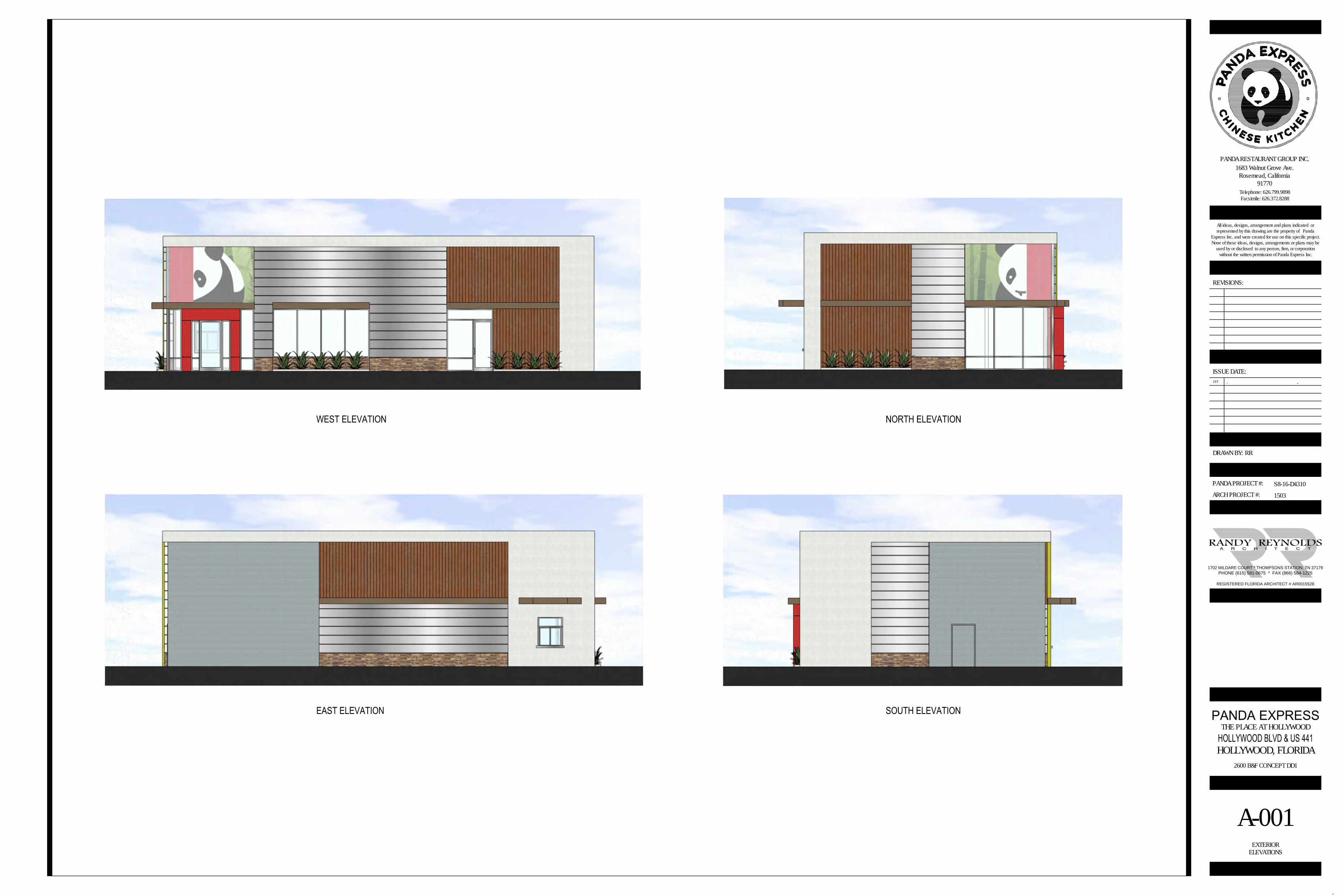
THE PLACE AT HOLLYWOOD
HOLLYWOOD, FLORIDA2600 B&F CONCEPT DD1
S8-16-D4310
1503
RR
1ST . .
PHONE (615) 591-0675 * FAX (866) 584-1225
1702 MILDARE COURT * THOMPSONS STATION, TN 37179
REGISTERED FLORIDA ARCHITECT # AR0015528
A-001EXTERIOR
ELEVATIONS

A-0021
Scale= 1/4" = 1'-0"
NORTH ELEVATION
ARCH PROJECT #:
PANDA PROJECT #:
DRAWN BY:
ISSUE DATE:
REVISIONS:
All ideas, designs, arrangement and plans indicated orrepresented by this drawing are the property of Panda
Express Inc. and were created for use on this specific project.None of these ideas, designs, arrangements or plans may be
used by or disclosed to any person, firm, or corporationwithout the written permission of Panda Express Inc.
1683 Walnut Grove Ave.Rosemead, California
91770Telephone: 626.799.9898Facsimile: 626.372.8288
PANDA RESTAURANT GROUP INC.
THE PLACE AT HOLLYWOOD
HOLLYWOOD, FLORIDA2600 B&F CONCEPT DD1
S8-16-D4310
1503
RR
1ST . .
PHONE (615) 591-0675 * FAX (866) 584-1225
1702 MILDARE COURT * THOMPSONS STATION, TN 37179
REGISTERED FLORIDA ARCHITECT # AR0015528
A-002EXTERIOR
ELEVATIONS
A-0022
Scale= 1/4" = 1'-0"
SOUTH ELEVATIONA-002
3Scale= NONE
EXTERIOR FINISH SCHEDULE
ARCH PROJECT #:
PANDA PROJECT #:
DRAWN BY:
ISSUE DATE:
REVISIONS:
All ideas, designs, arrangement and plans indicated orrepresented by this drawing are the property of Panda
Express Inc. and were created for use on this specific project.None of these ideas, designs, arrangements or plans may be
used by or disclosed to any person, firm, or corporationwithout the written permission of Panda Express Inc.
1683 Walnut Grove Ave.Rosemead, California
91770Telephone: 626.799.9898Facsimile: 626.372.8288
PANDA RESTAURANT GROUP INC.
THE PLACE AT HOLLYWOOD
HOLLYWOOD, FLORIDA2600 B&F CONCEPT DD1
S8-16-D4310
1503
RR
1ST . .
PHONE (615) 591-0675 * FAX (866) 584-1225
1702 MILDARE COURT * THOMPSONS STATION, TN 37179
REGISTERED FLORIDA ARCHITECT # AR0015528
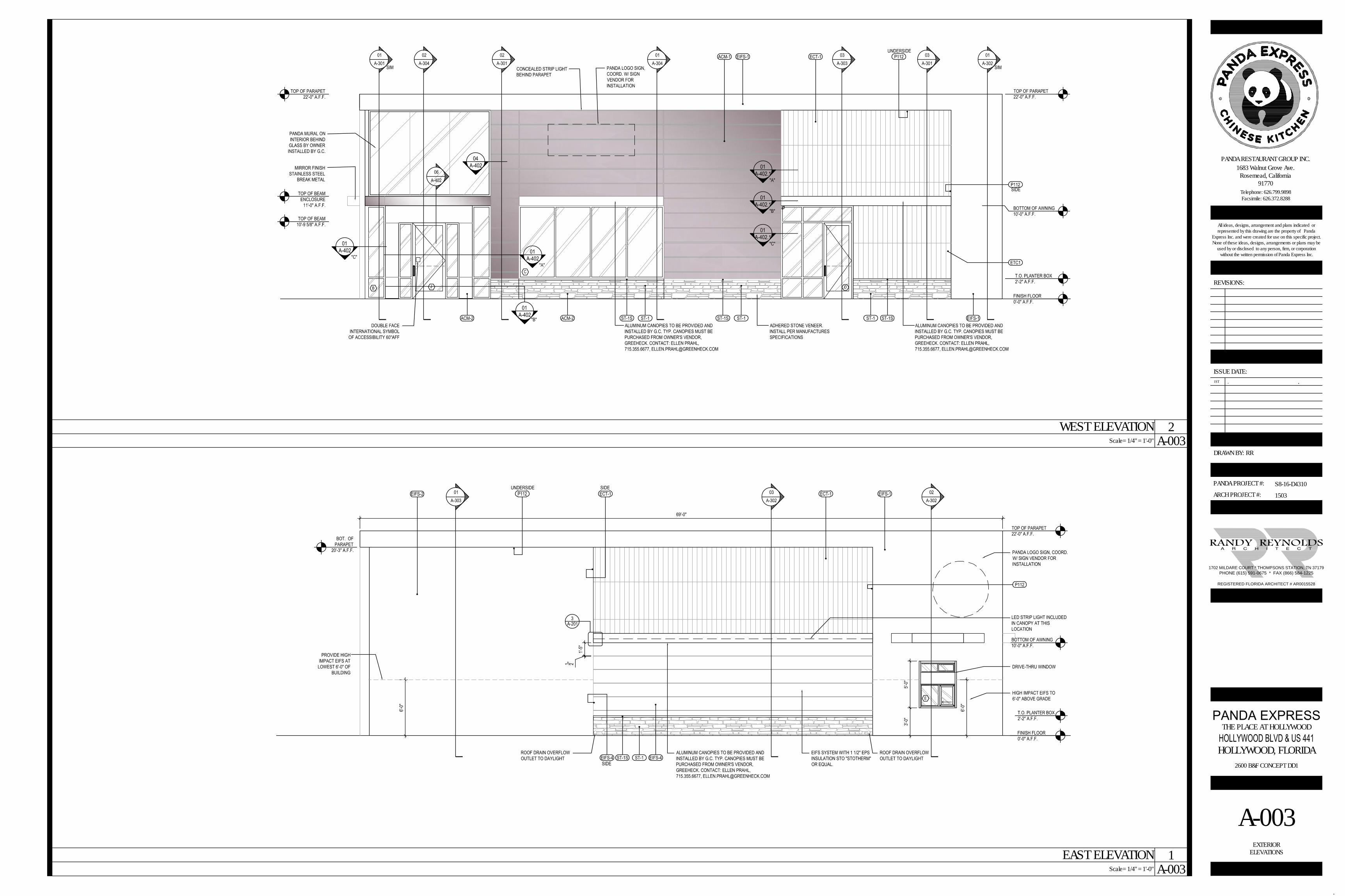
A-003EXTERIOR
ELEVATIONS
A-0031
Scale= 1/4" = 1'-0"
EAST ELEVATION
A-0032
Scale= 1/4" = 1'-0"
WEST ELEVATION