sla – oct. 07 bds-kom1 installation overview acknowledgment: f. peters, m. munro, j. kim g....
TRANSCRIPT

SLA – Oct. 07 BDS-KOM 1
Installation Overview
Acknowledgment:
F. Peters, M. Munro, J. Kim
G. Aarons, C. Corvin, P. Rodriguez
Fred Asiri/SLAC

SLAC-Oct. 07 BDS-KOM 2
Overview • Installation activities covers a large geographical area
– approximately 31 linear kilometers long which includes a complex network of about 72 km of underground tunnels at the depth of approximately 100m
• Requires the installation of – ~2,000 cryomodules, over 13,000 magnets and approximately
650 high level RF stations

SLAC-Oct. 07 BDS-KOM 3
Status of WBS 1.7.3 Installation
WBS Component
1 7 3 Installation
1 7 3 1 General Installation
1 Logistics Management
2 Engineering Support
3 Equipment
4 Vehicles
5 Shipping-Receiving
6 Warehousing
7 Surface Transport
1 7 3 2 Area System Installation
1 Sources e- Area Installation
2 Sources e+ Area Installation
3 Damping Ring Area Installation
4 RTML Area Installation
5 Main Linac Area Installation
6 Beam Delivery Area Installation
Area Systems3%
13%
21%
4%46%
13%Electron Source
Positron Source
Damping Ring
RTML Area
Main Linac
Beam Delivery
Level 5 Roll-up (~7M Labour Hours)
23%
77%
General Area System
BDS

SLAC-Oct. 07 BDS-KOM 4
Current Status of Central Area
BDS Large/Heavy Equipments Installation Access Shafts (9m ID)

SLAC-Oct. 07 BDS-KOM 5
ILC Magnet Count for the Area Systems
e- e+ e-DR e+DR e- Inj/Ext e+ Inj/ExtStyles Quantity Style Qty Qty Style Qty Qty Qty Qty Style Qty Style Qty Style Qty
Dipole 22 1351 6 25 152 2 126 126 8 8 6 716 0 0 8 190Normal Cond Quad 37 4134 13 76 840 4 747 747 76 76 5 1368 0 0 15 204
Supercond Quad 16 715 3 16 51 0 0 0 0 0 0 56 3 560 10 32 Sextupole 7 1050 2 0 32 2 504 504 0 0 0 0 0 0 3 10
Supercond Sextupole 4 12 0 0 0 0 0 0 0 0 0 0 0 0 4 12Normal cond Solenoid 3 38 3 12 26 0 0 0 0 0 0 0 0 0 0 0
Supercond Solenoid 4 14 1 2 0 0 0 0 0 0 1 8 0 0 2 4Normal cond Corrector 9 3836 1 0 840 3 450 450 0 0 4 2032 0 0 1 64
Supercond Corrector 14 1374 0 32 102 0 0 0 0 0 0 84 2 1120 12 36Pulsed/Kickers/Septa 13 319 1 0 21 4 68 68 0 0 3 70 0 0 5 92
Supercond Wiggler 1 160 0 0 0 1 80 80 0 0 0 0 0 0 0 0 NC Octupole/Muon Spoilers 2 6 0 0 0 0 0 0 0 0 0 0 0 0 2 6
Supercond Octupole 3 14 0 0 0 0 0 0 0 0 0 0 0 0 3 14Supercond Undulator 1 27 1 0 27 0 0 0 0 0 0 0 0 0 0 0
Overall Totals 136 13050 31 163 2091 16 1975 1975 84 84 19 4334 5 1680 65 664Totals w/o correctors 113 7840 ILC Magnet count for 250Gev on 250Gev beams with Interim Working Assumptions configuration
Total Normal cond 93 10734 FINAL QUANTITIES for the Reference Design ReportTotal Superconducting 43 2316 ~18% of all magnets are superconducting
8Dec06 version Compiled by Cherrill Spencer, ILC Magnet Systems Group. Send updated quantities to her.
Some cells you will see a quantity with zero styles-because same styleis used in more than one area and style is counted in just one area.
2 Linacs 2 BeamDelGrand TotalsMagnet Type
Sources Damping Rings 2 RTML
SLAC-Oct. 07 BDS-KOM 6
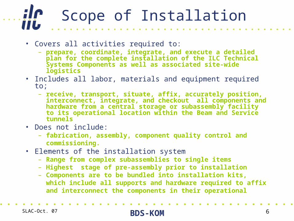
Scope of Installation
• Covers all activities required to:– prepare, coordinate, integrate, and execute a detailed plan for
the complete installation of the ILC Technical Systems Components as well as associated site-wide logistics
• Includes all labor, materials and equipment required to;– receive, transport, situate, affix, accurately position,
interconnect, integrate, and checkout all components and hardware from a central storage or subassembly facility to its operational location within the Beam and Service tunnels
• Does not include:– fabrication, assembly, component quality control and
commissioning.• Elements of the installation system
– Range from complex subassemblies to single items– Highest stage of pre-assembly prior to installation– Components are to be bundled into installation kits, which
include all supports and hardware required to affix and interconnect the components in their operational

SLAC-Oct. 07 BDS-KOM 7
Methodology- ExampleMethodology- Example
Gas Return Pipe
40 K Pipe
4 K Pipe
Cool down
RF Power Coupler
RF Coupler Vacuum
Beam Pipe
2 K Pipe
80 K Pipe
4 K Pipe
2.2 K Pipe
40 K shield
4 K shield
Module Connections
One of 556 Main Linac (RF) Unit ~ 38 Meter
Installation Sequence• Prepare tunnel section for installation…• Move, place, adjust and fix Cryomodule supports…• Move Cryomodules from access shaft to installation section… • Install, adjust, fix, and prepare section for Cryogenic & Beam Pipe connections…• Complete Cryogenic and Vacuum connections, leak check, then connect the Cryomodule sleeve coupling

SLAC-Oct. 07 BDS-KOM 8
Cryomodule ConnectionsPipe welding procedure e.g.:Prepare joints, tools, etc. 1. Place welding machine2. Check setup with one test run3. Execute welding procedure4. Remove welding machine5. Setup visual control monitor6. Execute control procedure 7. Remove control monitor8. Go to next pipe
Use:• 10 man-days per interconnect for cryogenic pipes and superconducting joints, Tom Peterson, 11/9/2006Tom Peterson, 11/9/2006• 7 man-days per connection for vacuum joints, 7 man-days per connection for vacuum joints, John Noonan, 11/9/2006John Noonan, 11/9/2006
Gas Return Pipe
40 K Pipe
4 K Pipe
Cool down
RF Power Coupler
RF Coupler Vacuum
Beam Pipe
2 K Pipe
80 K Pipe
4 K Pipe
2.2 K Pipe
40 K shield
4 K shield
Cryomodule Installation – Assumptions

SLAC-Oct. 07 BDS-KOM 9
Cryomodule Installation – Assumptions
BEAM TUNNELOccupancy During Installation
Ducts Long
Distance
Life Safety Systems
• Fire suppression
• Fire detection sensor
• Area lighting
• Backup lighting
• Life safety circuit conduits
• Low O2 detection & alarm
• Exit lighting
• Fire controls & alarm
• Communication systems
• Emergency all stop
• Fire pull station
• Conveyance charging
BEAM TUNNEL Readiness at Joint Occupancy
WaveguideAlignment
Space
LINAC
Area

SLAC-Oct. 07 BDS-KOM 10
Installation Planning Model
Shaft 7 (9m DIA)
Shaft 11 (14m DIA) Shaft 3 (14m DIA)
Shaft 1.0 (9m DIA)
Shaft 1.2 (16m DIA)
Shaft 1.1 (16m DIA)
Shaft 2 (14m DIA) Shaft 4 (14m DIA)
Shaft 6 (9m DIA)
Shaft 10 (14m DIA)
Shaft 5 (14m DIA)
4.5 km4.5 km
Shaft 13 (9m DIA)
Shaft 12 (9m DIA)
RTML1.3 km
Underground Layout with Installation Access Shafts
Installation planning of the large and complex ILC machine requires the creation of 3-D computer models of all the major components as well as the underground works.

SLAC-Oct. 07 BDS-KOM 11
Installation Model for Main Linac Components in Underground Segment
Installation of BDS Major Components (e.g. Magnets) Modeled and Scaled Based on the Cryomodules

SLAC-Oct. 07 BDS-KOM 12
EDR PLANNING
Refine the 3D drawings of the tunnel and insert brief overall drawings of the technical equipment and integrate with a time and motion software
Superimpose the surface warehouses, the staging assembly buildings and the elevator access shafts
Prepare alternate installation approach systems, to facilitate the best way to perform the installation
Evaluate elevator transport options for materials, to support installation activities
Design the main material transport system, for accelerator part movement, in the tunnel, then manufacture and test, a prototype vehicle
Check out utility access locations for an efficient installation Build a mockup of a tunnel section and using outline models of the
most difficult pieces of accelerator equipment to install, go through the installation procedures, to proof out the material handling equipment and fixtures/tooling to be used
The mockup could also be used as an installation training site and for the evaluation of safety procedures
Define support equipment required. This will include vacuum support equipment, such as leak checkers, materials handling equipment, fixtures, tooling, etc.

SLAC-Oct. 07 BDS-KOM 13
Major inputs required for the underground installation
• Basic civil engineering layouts of the facility, including surface building locations, access roads & tunnel layouts.
• Preliminary outline drawings of the various pieces of equipment to be installed in the tunnel. These details should include mechanical, electrical & utility equipment requirements.
• Details of the physical locations of all pieces, of equipment to be placed in the tunnel.
• Location of all utility connections in the tunnel.• Cryogenic system connection box locations, in the tunnel. • Develop flow charts, showing the typical sequence of events, per
major equipment item, in the installation process. • Approximate schedule of facility completion, plus delivery dates &
sequence of equipment deliveries to the site.• An inventory control system that incorporates input data, output
data & documentation.• Safety/emergency features in the tunnel & on the surface.• Details of the quality & quantity of local labor available, to support
the installation.

SLAC-Oct. 07 BDS-KOM 14
EDR PLANNING
Data Processing:• An inventory control system to cover, receiving,
scheduling, installation planning & documentation reproduction, will be required. This type information should be readily accessible, at many points on the site.
• Quick part data identification, can enhance our ability, to perform the installation. Several types of part identification equipment are available, including RFID, Data Matrix & Bar Coding; these should be evaluated regarding the site requirements, as some of them need relatively expensive writers & readers, plus some vendors, may not have this capability

SLAC-Oct. 07 BDS-KOM 15
Added Values
• Centralized information database– Sharing and synchronization of records, files
• Easy and fast communication• Better-informed planning decisions from
– Operation optimization• Feasibility study with resource loaded production plan• Global optimization
– Interference detection• Physical interferences detection• Work space conflicts detection• Analysis of the severity of the interferences and conflicts
• Real-time tracking and reporting– Status check for individual equipment
• Fabrication, transit, storage, sub-assembly, installation
• Comparison between planned and actual

SLAC-Oct. 07 BDS-KOM 16
Application of Virtual Design & Construction Technologies
3D model(AutoCAD)
4D model / interference check
(NavisWorks)
Scheduling(Primavera)
IntegratedCentral
4D Database(Enterprixe)
Mobile Server
FabricatorJob Site
Mobile Technology
Operation Optimization
Discrete event simulation
(Strobscope)
Database Technology
Transporter
4D Technology (3D CAD + schedule)

SLAC-Oct. 07 BDS-KOM 17
EDR/FY08 Budgetary Plan
• Goal: To set up a logistics management database for the ILC to accomplish and optimize the installation process management1. Set-up a Data Base software to
• Define scope of on site deliverable for each subsystem• Define the subsystem installation requirements• Establish subsystem interfaces/Boundaries
2. Set-up and launch a 4D computer software program (CATIA) to integrate 3D geometry with time motion simulation
• Check for space time conflict management• Maximize efficiency, labor loading, and material delivery
sequencing
April Budget Plan Reduced Budget Model
WBS Level FTEs M&S FTEs M&S
WBS 2.2.3.1 Installation 2.0 120 1.75 0