fred asiri1 conventional facilities activities @ slac april 9, 2006 acknowledgment: clay corvin,...
TRANSCRIPT

Fred Asiri 1
Conventional Facilities Activities @ SLAC
April 9, 2006
Acknowledgment: Clay Corvin, Jerry Aarons, and Jonghoon Kim

Fred Asiri 2
Conventional Facilities Activities @ SLAC
Summary :• Support the CF&S Global System group
effort
• Support the Installation Global System task
• Support the ILC R&D program in SLAC

Fred Asiri 3
C F & S Activities Update (Since 3/5/07)
• Working with CF groups in American, European and Working with CF groups in American, European and Asian Regions, completed the text for the Conventional Asian Regions, completed the text for the Conventional Facilities portion of the RDR just in timeFacilities portion of the RDR just in time– Condensed portion is posted in the RDRCondensed portion is posted in the RDR– While the complete and comprehensive version, will be issued While the complete and comprehensive version, will be issued
as a companion document to the RDRas a companion document to the RDR• This document provides a detailed description of the ILC This document provides a detailed description of the ILC
Conventional Facilities and Siting (CF&S) consistent with the RDR Conventional Facilities and Siting (CF&S) consistent with the RDR cost estimate, it is organized to follow the RDR, providing additional cost estimate, it is organized to follow the RDR, providing additional detail and explanation.detail and explanation.
• Working with Fermilab’s CF&S (FESS) Environmental Working with Fermilab’s CF&S (FESS) Environmental Specialist Rod WaltonSpecialist Rod Walton– Developing plans – assembling list of applicable Environmental
Regulations, estimated schedule & budgetary costs for the American regions, reference site
Fred Asiri 4
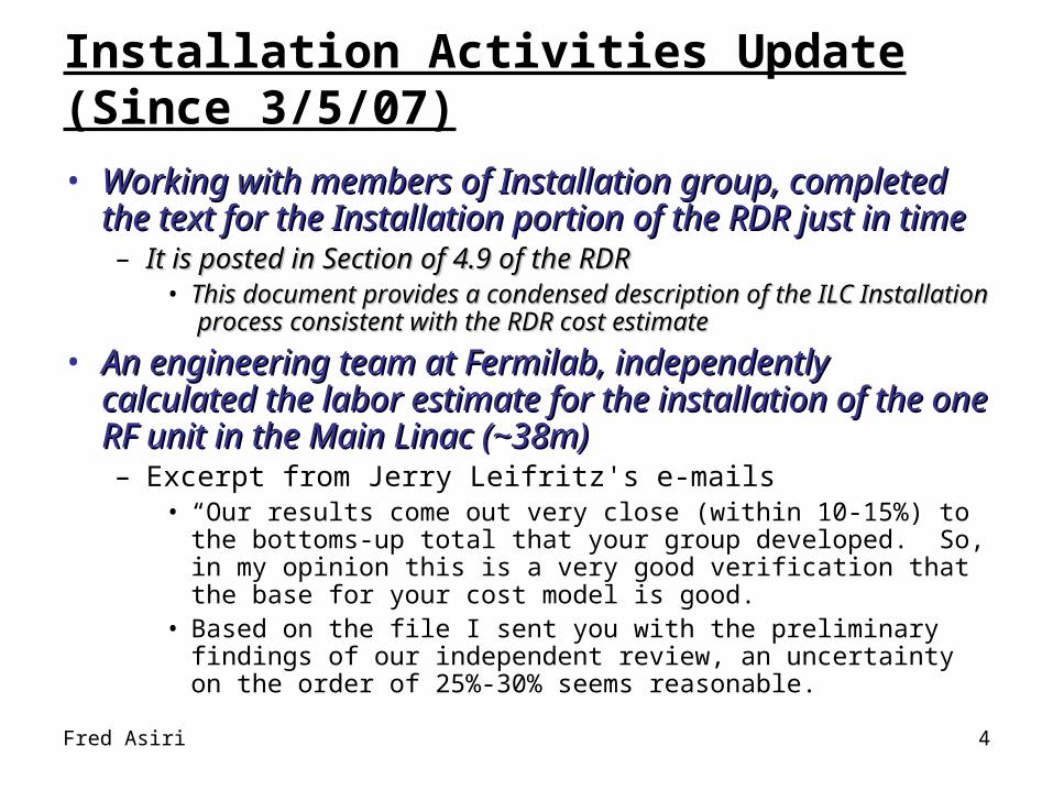
Installation Activities Update (Since 3/5/07)
• Working with members of Installation group, completed Working with members of Installation group, completed the text for the Installation portion of the RDR just in timethe text for the Installation portion of the RDR just in time– It is posted in Section of 4.9 of the RDRIt is posted in Section of 4.9 of the RDR
• This document provides a condensed description of the ILC This document provides a condensed description of the ILC Installation process consistent with the RDR cost estimate Installation process consistent with the RDR cost estimate
• An engineering team at Fermilab, independently An engineering team at Fermilab, independently calculated the labor estimate for the installation of the calculated the labor estimate for the installation of the one RF unit in the Main Linac (~38m)one RF unit in the Main Linac (~38m)– Excerpt from Jerry Leifritz's e-mails
• “Our results come out very close (within 10-15%) to the bottoms-up total that your group developed. So, in my opinion this is a very good verification that the base for your cost model is good.
• Based on the file I sent you with the preliminary findings of our independent review, an uncertainty on the order of 25%-30% seems reasonable.

Fred Asiri 5
Installation Activities Update (Since 3/5/07)
Subsystem installation underground Location Units % Low High Assumptions
1 Cryomodules ML* 1668 20 17.5 22.49 Optimized for installation
2 RF Power distribution system ML 1668 20 17.5 22.49 One unit per Cryo Module
3 Beam Lines: Magnets, supports, pipes etc. ML 10 7.5 12.49 Optimized for installation
4 Modulator & HV pulse transformer ST* 556 10 7.5 12.49 Container versions
5 Electronic racks and local control cable ST 556 10 7.5 12.49 Ready to go assembly
6 Klystron include shielding ST 556 5 2.5 7.49 Klystron on wheels
7 AC Power station & distribution ST 556 5 2.5 7.49 Container version
8 Cooling water station & distribution ST 556 5 2.5 7.49 Container version
9 Air condition system, fan, ducts etc. ST 556 5 2.5 7.49 Optimized for installation
10 Miscellaneous * * 10 7.5 12.49 From different sub systems
Installation underground 100 75 124.90
100 -25 25
Staff Low High450 338 562
Nominal number and tolerance
• Performed Installation Uncertainty calculation, results:Performed Installation Uncertainty calculation, results:– General Installation uncertainty estimate is about ± 30%– Main Linac Installation uncertainty estimate is about ± 25%– Rest of Area System Installation uncertainty estimate use -30% + 25%
• Sample; uncertainty calculation for the Main Linac

Fred Asiri 6
Collaboration with CIFE
• CEE 211 class “multidisciplinary modeling and analysis”
• Used the ILC equipment installation plan as a case in this class
• Project team: two graduate students (Esther Kweon, Jung In Kim) and Jonghoon Kim
• Goal of this case study– To explore the possibility of increasing the certainty of equipment installation
plan in ILC project– To test if the following software tools that enable 4D model based time-space
conflict detection and analysis are suitable for our project
• Software tools used and the capabilities of the tools tested– AutoCAD (3D modeling)– CATIA (3D modeling)– Primavera (Scheduling)– Navisworks (4D modeling and time-space conflicts detection)

Fred Asiri 7
Project results
• 4D model-based time-space conflict detection
3D model
Installation schedule
4D model-based time-space conflict detection
Equipment installation sequence and time

Fred Asiri 8
Project results
• An example of time-space conflict in the original installation schedule
• Improved installation schedule– Decreased time-space conflicts– Same total duration
Original Schedule Alternative Schedule
Working on mitigationSequence change between “Supply and exhaust ventilation”, “Beam line”, “Fire suppression, and “”Chilled water skid and
piping”
Number of time-space conflicts 236 170(30% decreased)
“Fan Coil unit installation” and “piping installation” is too close and have a time-space conflict
Conflict amount (m) Conflict time Location

Fred Asiri 9
Conclusions
• 4D-based time-space conflicts analysis can– Detect unpredictable time-space conflicts of equipment installation schedule– Provide detailed information about detected time-space conflicts
• Equipment and activity list that conflict each other
• Times of the time-space conflicts detected
• Locations of time-space conflicts detected
• Severities of time-space conflicts detected
– Visualize installation process and detected time-space conflicts– Make clear where the installation schedule needs to be improved– Consequently, enable planner to increase the certainty of equipment installation
plan
• Software tools that we used and tested are suitable for installation schedule optimization in our project
• Next, to test the above software capability to check for possible interference during the transport and installation of equipment