sketch-based procedural surface modeling and … schmidt & karan singh / sketch-based procedural...
TRANSCRIPT

EUROGRAPHICS 2008 / G. Drettakis and R. Scopigno(Guest Editors)
Volume 27 (2008), Number 3
Sketch-Based Procedural Surface Modeling and CompositingUsing Surface Trees
Ryan Schmidt† and Karan Singh†
Dynamic Graphics ProjectUniversity of Toronto, Canada
Abstract
We present a system for creating and manipulating layered procedural surface editing operations, which is mo-tivated by the limited support for iterative design in free-form modeling. A combination of sketch-based and tra-ditional modeling tools are used to design soft displacements, sharp creases, extrusions along 3D paths, andtopological holes and handles. Using local parameterizations, these edits are combined in a dynamic hierarchy,enabling procedural operations like linked copy-and-paste and drag-and-drop layer-based editing. Such dynamic,layered “surface compositing” is formalized as a Surface Tree, an analog of CSG trees which generalizes previ-ous hierarchical surface modeling techniques. By “anchoring” tree nodes in the parameter space of lower layers,our surface tree implementation can better preserve the semantics of an edit as the underlying surface changes.Details of our implementation are described, including an efficient procedural mesh data structure.
Categories and Subject Descriptors (according to ACM CCS): I.3.5 [Computer Graphics]: Computational Geometryand Object Modeling
1. Introduction
Creating 3D models is a notoriously difficult task, in partbecause 3D modeling interfaces are so complex. One of thegoals underlying much of the research in shape modeling isto make creating models more efficient. Although 3D designis largely a process of trial-and-error, most tools operate un-der the assumption that the designer will carry out editingoperations sequentially. Operation n can be tweaked indef-initely, but becomes immutable once operation n + 1 is ini-tialized. “Undo” allows operation n to be modified, but onlyby discarding all following operations. This workflow resultsin much repeated work during design iterations.
Procedural modeling interfaces such as the ShapeShopsystem [SWSJ05] support a more efficient workflow by al-lowing the designer to “go back in time” and directly mod-ify any offending editing operation. However, we have foundthat 3D artists use ShapeShop only to create coarse models,
† {rms | karan}@dgp.toronto.edu
and prefer to add detail by exporting static meshes to tradi-tional surface deformation tools. As a result, all the benefitsof the procedural representation are lost. The system we de-scribe here is motivated by the desire to support the directsurface editing tools that artists demand, in a procedural in-terface. Recent works such as Fibermesh [NISA07] and lay-ered subdivision [WM07] also address procedural surfacemodeling, but neither supports the intuitive drag-and-droplayered surface editing that our system demonstrates.
Our main contribution is a system which fuses sketch-based interaction with a 3D analog of the intuitive layer-based metaphors found in 2D graphic design tools suchas Adobe Illlustrator [Ado07]. With our interface, design-ers use sketches to layer large-scale edits, fine details, andeven topological change onto an initial base surface. Theseedits are completely procedural - at any time the designercan manipulate parameters, copy-and-paste, or even drag ed-its along the surface (Figure 1). Layered updates attempt topreserve the intended “semantics” of edits - if operation nis modified, operation n + 1 is “played back” relative to thenew output of operation n.
c© The Eurographics Association and Blackwell Publishing 2007. Published by BlackwellPublishing, 9600 Garsington Road, Oxford OX4 2DQ, UK and 350 Main Street, Malden,MA 02148, USA.
Ryan Schmidt & Karan Singh / Sketch-Based Procedural Surface Modeling and Compositing Using Surface Trees
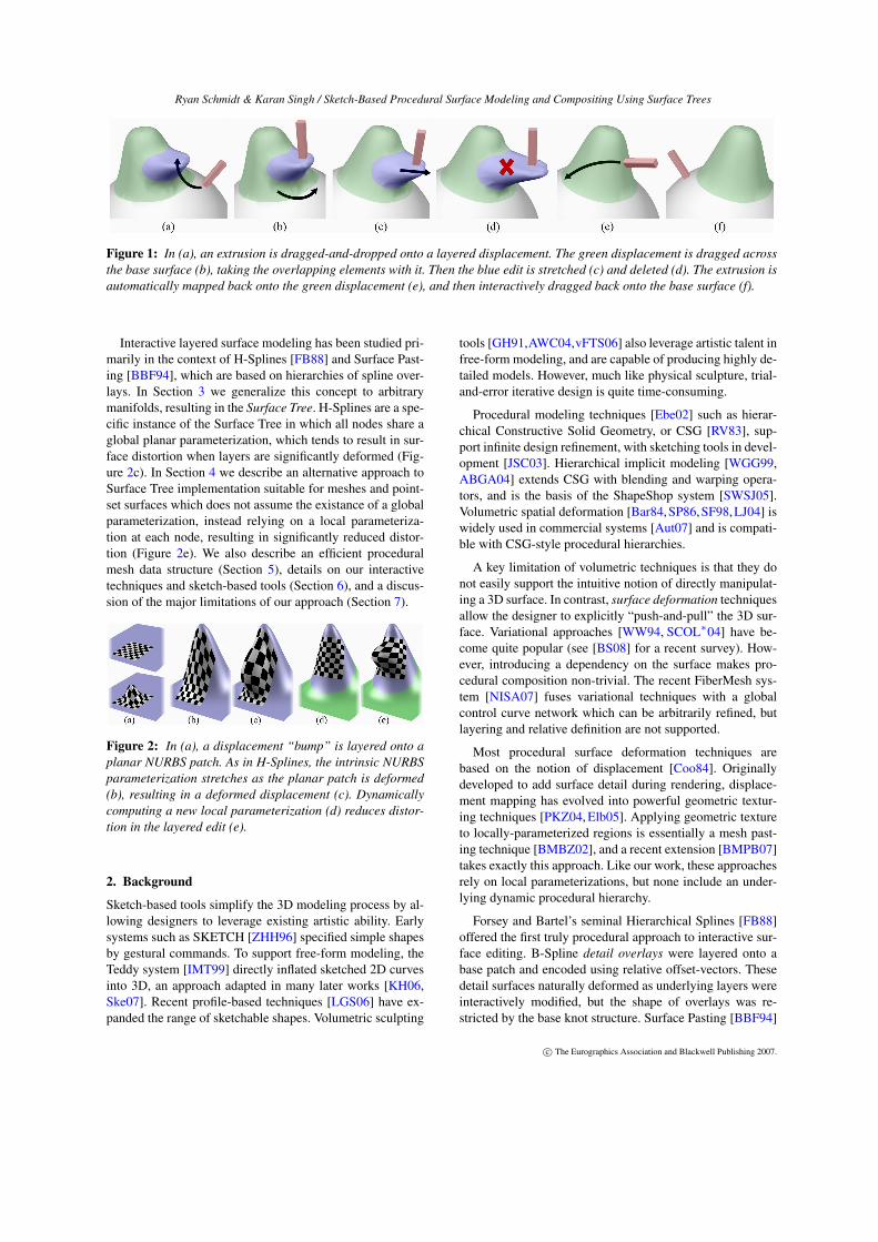
Figure 1: In (a), an extrusion is dragged-and-dropped onto a layered displacement. The green displacement is dragged acrossthe base surface (b), taking the overlapping elements with it. Then the blue edit is stretched (c) and deleted (d). The extrusion isautomatically mapped back onto the green displacement (e), and then interactively dragged back onto the base surface (f).
Interactive layered surface modeling has been studied pri-marily in the context of H-Splines [FB88] and Surface Past-ing [BBF94], which are based on hierarchies of spline over-lays. In Section 3 we generalize this concept to arbitrarymanifolds, resulting in the Surface Tree. H-Splines are a spe-cific instance of the Surface Tree in which all nodes share aglobal planar parameterization, which tends to result in sur-face distortion when layers are significantly deformed (Fig-ure 2c). In Section 4 we describe an alternative approach toSurface Tree implementation suitable for meshes and point-set surfaces which does not assume the existance of a globalparameterization, instead relying on a local parameteriza-tion at each node, resulting in significantly reduced distor-tion (Figure 2e). We also describe an efficient proceduralmesh data structure (Section 5), details on our interactivetechniques and sketch-based tools (Section 6), and a discus-sion of the major limitations of our approach (Section 7).
Figure 2: In (a), a displacement “bump” is layered onto aplanar NURBS patch. As in H-Splines, the intrinsic NURBSparameterization stretches as the planar patch is deformed(b), resulting in a deformed displacement (c). Dynamicallycomputing a new local parameterization (d) reduces distor-tion in the layered edit (e).
2. Background
Sketch-based tools simplify the 3D modeling process by al-lowing designers to leverage existing artistic ability. Earlysystems such as SKETCH [ZHH96] specified simple shapesby gestural commands. To support free-form modeling, theTeddy system [IMT99] directly inflated sketched 2D curvesinto 3D, an approach adapted in many later works [KH06,Ske07]. Recent profile-based techniques [LGS06] have ex-panded the range of sketchable shapes. Volumetric sculpting
tools [GH91,AWC04,vFTS06] also leverage artistic talent infree-form modeling, and are capable of producing highly de-tailed models. However, much like physical sculpture, trial-and-error iterative design is quite time-consuming.
Procedural modeling techniques [Ebe02] such as hierar-chical Constructive Solid Geometry, or CSG [RV83], sup-port infinite design refinement, with sketching tools in devel-opment [JSC03]. Hierarchical implicit modeling [WGG99,ABGA04] extends CSG with blending and warping opera-tors, and is the basis of the ShapeShop system [SWSJ05].Volumetric spatial deformation [Bar84,SP86,SF98,LJ04] iswidely used in commercial systems [Aut07] and is compati-ble with CSG-style procedural hierarchies.
A key limitation of volumetric techniques is that they donot easily support the intuitive notion of directly manipulat-ing a 3D surface. In contrast, surface deformation techniquesallow the designer to explicitly “push-and-pull” the 3D sur-face. Variational approaches [WW94, SCOL∗04] have be-come quite popular (see [BS08] for a recent survey). How-ever, introducing a dependency on the surface makes pro-cedural composition non-trivial. The recent FiberMesh sys-tem [NISA07] fuses variational techniques with a globalcontrol curve network which can be arbitrarily refined, butlayering and relative definition are not supported.
Most procedural surface deformation techniques arebased on the notion of displacement [Coo84]. Originallydeveloped to add surface detail during rendering, displace-ment mapping has evolved into powerful geometric textur-ing techniques [PKZ04, Elb05]. Applying geometric textureto locally-parameterized regions is essentially a mesh past-ing technique [BMBZ02], and a recent extension [BMPB07]takes exactly this approach. Like our work, these approachesrely on local parameterizations, but none include an under-lying dynamic procedural hierarchy.
Forsey and Bartel’s seminal Hierarchical Splines [FB88]offered the first truly procedural approach to interactive sur-face editing. B-Spline detail overlays were layered onto abase patch and encoded using relative offset-vectors. Thesedetail surfaces naturally deformed as underlying layers wereinteractively modified, but the shape of overlays was re-stricted by the base knot structure. Surface Pasting [BBF94]
c© The Eurographics Association and Blackwell Publishing 2007.

Ryan Schmidt & Karan Singh / Sketch-Based Procedural Surface Modeling and Compositing Using Surface Trees
addresses this limitation, by allowing arbitrary NURBSpatches to be hierarchically pasted to a base spline patch.
Surface pasting was initially developed to quickly approx-imate layered spline displacement [BF93] by trimming holesin the base spline and simply positioning the “paste” sur-face in the trimmed hole. Although the result is only “ε-continuous”, it is highly interactive, and has been applied inthe commercial modeling package Houdini [Sid07]. Whilethe initial system was limited to interaction in parameterspace, an interface for directly positioning pasted surfaceshas been developed [CMB97]. However, this “world-space”interaction is ultimately mapped into the parametric domain,exposing a critical limitation of surface pasting - it’s relianceon the base patch parameterization. As underlying patchesare manipulated, the shape of the pasted surface follows the(frequently un-intuitive) distortions that occur in parameterspace [TM98]. The assumption of an underlying global pla-nar parameterization also makes topology change problem-atic [SM03]. One of the key contributions of our work is todevelop a framework which resolves these limitations.
Multiresolution surfaces [ZSS97, LDW97, GKSS02]adapt the H-Spline concept to mesh representations. How-ever, the detail vector hierarchies used in these approachesare derived automatically, and thus lack the user-constructedsemantics found in Surface Pasting and our Surface Trees. Anotable exception is [WM07], in which a dependency graphof sketched subdivision curves and surfaces are inflated into3D volumes. A layered subdivision “skin” blends these vol-umes together. While this approach is promising, proceduralediting operations are constrained to mesh faces in the cur-rent subdivision hierarchy, preventing the intuitive drag-and-drop surface compositing provided by our system.
3. Defining Surface Trees
Hierarchical volumetric modeling techniques [RV83,WGG99] represent complex volumes using trees of com-position nodes, with primitive shapes at the leaves. Thepower of these data structures is that any composition nodeor primitive can be trivially replaced with another. In thissection we define an analogous structure for representingdirect surface manipulations - a Surface Tree.
At a conceptual level, a surface editing operation replacesa bounded region U on a surface S with an open surface V ,where the boundary ∂V coincides with ∂U . Each node N inour Surface Tree simply carries out this replacement:
N (S,U ,V) = (S \U) ∪ V (1)
N can be thought of as a surface compositing operation, andhence a complex surface can be recursively defined by ap-plying nodes to a base surface B:
Si+1 =Ni(Si,Ui,Vi)
S1 =N0(B,U0,V0)
Intuitively, the final output surface is defined by incremen-tally layering a series of surface patches Vi onto B. Althoughthe recursion above is sequential in nature, any Vi can bedefined by another series of compositions. Hence, a SurfaceTree is a structured binary tree of composition nodesN , witha primary branch that contains B as the initial leaf node, anda series of nested secondary branches which feed into theVi’s of the primary branch (Figure 3).
Figure 3: A surface editing operation locally replaces someregion U of a surface. In a Surface Tree, editing operationscan be applied hierarchically, although secondary branchesmust always output open surfaces to be properly merged.
Note that the arguments to N are not independent. S canbe any surface, but it is necessary that U ⊆ S, and V mustalways be an open surface patch. This implies that only Bcan be a closed surface - all Vi’s must have an open boundary(and hence so must all secondary branches).
In the equations above, we assumed that ∂V = ∂U . Theeasiest way to ensure this is to define V = E(U), where Eis a boundary-preserving editing operation. Although arbi-trarily complex edits are possible, assume for now that E isa displacement map. The above definition allows V to beprocedurally re-computed if U changes. However, if the de-signer changes U0 in Figure 3, S1 will change, and U1 willneed to be procedurally re-computed (Figure 4).
To ensure maximum flexibility, It is desirable that the re-computation of U be as independent of S as possible. Oneway to accomplish this is to use the tools of Riemanniangeometry [DoC94]. We restrict S to 2-manifolds embeddedin R3, guaranteeing that any point on S has a local neigh-bourhood with disc-like topology. S is then covered witha finite atlas of topological discs, referred to as coordinatepatches. A mapping P known as a planar parameterizationexists between each 3D patch and R2. Given an atlas on S,we can now encode U as a mapping from some 2D region uof the atlas parameter-space to the 3D surface. To simplifythe following exposition, assume that U is contained withina single coordinate patch with parameterization PU . Thenwe can write U(u) = PU (u), and rewrite Equation 1 as
N (S,u,E) = (S \U(u)) ∪ E(U(u)) (2)
With this formulation, Surface Tree nodes can be proce-durally re-computed because the editing region U is encoded
c© The Eurographics Association and Blackwell Publishing 2007.

Ryan Schmidt & Karan Singh / Sketch-Based Procedural Surface Modeling and Compositing Using Surface Trees
independent of the current 3D embedding of the input sur-face S. Instead, it depends on the parameterization. Unfor-tunately, to build a practical system using arbitrary mesh orpoint-set representations, we must avoid assuming the ex-istence of a global, consistent manifold parameterization aswe have no way of maintaining such a manifold in real-time.This is problematic because we now lack a global embed-ding space in which to fix the location and shape of eachlayer. In the next section, we describe how we deal with thisissue and implement Surface Trees in our interactive system.
Figure 4: In (a), a displacement is applied to U ⊆ S tocreate an edited region V . If U is changed, V can be re-computed (b), but how can U be re-computed if S changes(c)? One solution is to write U as a function of a 2D pa-rameterization of S (d). Then if S is deformed, U can bere-computed from the parameterization (e), allowing V tobe applied to the new surface (f).
4. Implementing a Surface Tree
In Section 3 we described a mathematical formulation of aSurface Tree. In this section we provide details on our im-plementation, focusing on how the tree is constructed andupdated. To begin, we assume that surfaces S are trianglemeshes, although our approach is also applicable to pointsets and arbitrary polygonal meshes.
Following Equation 1, a Surface Tree node N is a proce-dural operator which applies an editing operation to an inputsurface. In our system, the node operator is defined as
Sout =N (Sin,u,r,E) (3)
where u is a single point embedded in some parameteriza-tion, r is the radius of a geodesic disc which contains U (ex-plained below), and E is a mesh editing operation.
Our basic approach is as follows. The primary branch ofour Surface Tree begins with a base mesh B and incremen-tally applies procedural editing operations:
Si+1 =Ni(Si,ui,ri,Ei)
S1 =N0(B,u0,r0,E0)
Editing regions U are defined as parameterized trianglepatches which approximate geodesic discs of radius r cen-tered at seed points p. These per-node parameterizations arere-used to approximate a global manifold - the anchor point
ui of each node is embedded in the parameterization com-puted for some upstream node N j<i. Hence, when evaluat-ing Equation 3, we project ui to the seed point pi on thecurrent surface Si to find Ui (see Figure 5).
Figure 5: To evaluate node Ni, we first map the anchorpoint ui forward from the upstream node N j<i that it is em-bedded in to the seed point p on the input surface Si. Nextwe compute the editing region U by segmenting from Si anapproximate geodesic disc with radius ri around p, para-meterize it, and generate the edited region V . Finally V iscombined with Si \U to produce the output surface Si+1.
Our procedural editing operations (Section 6) share acommon foundation, in that they are defined as boundary-preserving modifications to one or more parameterized geo-desic discs. Given a seed point p and geodesic radius r,we use Dijkstra’s algorithm [Dij59] to segment an (approxi-mate) geodesic disc from the mesh and parameterize it, cre-ating the editing regionU (Figure 6). While many parameter-ization algorithms are known [SPR06], we use the DiscreteExponential Map [SGW06] because it produces consistentdistortion and is computed in-line with Dijkstra’s algorithm.
Figure 6: Given a seed point p on surface Si (a), we segmenta geodesic disc with radius ri (b), parameterize it (c), andapply a deformation (d).
4.1. Node Anchoring and Updating
As noted, we lack a global atlas which can be used to fixthe position of each editing layer. We do, however, have aparameterized support region computed for each editing op-eration. Hence, we can embed the seed point p of an edit asan anchor point ui in the existing parameterization of someupstream node N j. This creates a dependency between Niand N j (Figure 7), so our Surface Tree is not strictly a tree,but rather a highly structured dependency graph [Hae88].
This anchor point approach inherently avoids the ambigu-ous case where an editing region U overlaps the boundaries
c© The Eurographics Association and Blackwell Publishing 2007.
Ryan Schmidt & Karan Singh / Sketch-Based Procedural Surface Modeling and Compositing Using Surface Trees
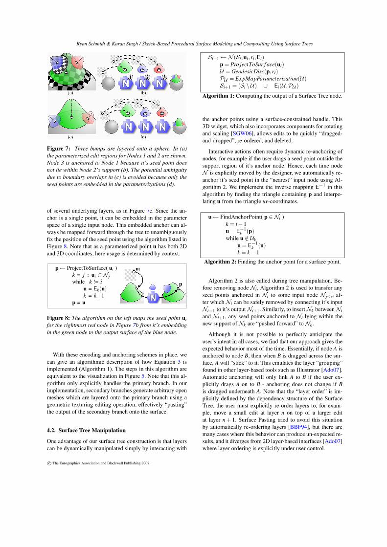
Figure 7: Three bumps are layered onto a sphere. In (a)the parameterized edit regions for Nodes 1 and 2 are shown.Node 3 is anchored to Node 1 because it’s seed point doesnot lie within Node 2’s support (b). The potential ambiguitydue to boundary overlaps in (c) is avoided because only theseed points are embedded in the parameterizations (d).
of several underlying layers, as in Figure 7c. Since the an-chor is a single point, it can be embedded in the parameterspace of a single input node. This embedded anchor can al-ways be mapped forward through the tree to unambiguouslyfix the position of the seed point using the algorithm listed inFigure 8. Note that as a parameterized point u has both 2Dand 3D coordinates, here usage is determined by context.
Figure 8: The algorithm on the left maps the seed point uifor the rightmost red node in Figure 7b from it’s embeddingin the green node to the output surface of the blue node.
With these encoding and anchoring schemes in place, wecan give an algorithmic description of how Equation 3 isimplemented (Algorithm 1). The steps in this algorithm areequivalent to the visualization in Figure 5. Note that this al-gorithm only explicitly handles the primary branch. In ourimplementation, secondary branches generate arbitrary openmeshes which are layered onto the primary branch using ageometric texturing editing operation, effectively “pasting”the output of the secondary branch onto the surface.
4.2. Surface Tree Manipulation
One advantage of our surface tree construction is that layerscan be dynamically manipulated simply by interacting with
Si+1←N (Si,ui,ri,Ei)p = Pro jectToSur f ace(ui)U = GeodesicDisc(p,ri)PU = ExpMapParameterization(U)Si+1 = (Si \U) ∪ Ei(U ,PU )
Algorithm 1: Computing the output of a Surface Tree node.
the anchor points using a surface-constrained handle. This3D widget, which also incorporates components for rotatingand scaling [SGW06], allows edits to be quickly “dragged-and-dropped”, re-ordered, and deleted.
Interactive actions often require dynamic re-anchoring ofnodes, for example if the user drags a seed point outside thesupport region of it’s anchor node. Hence, each time nodeN is explicitly moved by the designer, we automatically re-anchor it’s seed point in the “nearest” input node using Al-gorithm 2. We implement the inverse mapping E−1 in thisalgorithm by finding the triangle containing p and interpo-lating u from the triangle uv-coordinates.
u← FindAnchorPoint( p ∈Ni )k = i−1u = E−1
k (p)while u /∈ Uk
u = E−1k (u)
k = k−1
Algorithm 2: Finding the anchor point for a surface point.
Algorithm 2 is also called during tree manipulation. Be-fore removing node Ni, Algorithm 2 is used to transfer anyseed points anchored in Ni to some input node N j<i, af-ter which Ni can be safely removed by connecting it’s inputNi−1 to it’s outputNi+1. Similarly, to insertNk betweenNiand Ni+1, any seed points anchored to Ni lying within thenew support ofNk are “pushed forward” toNk.
Although it is not possible to perfectly anticipate theuser’s intent in all cases, we find that our approach gives theexpected behavior most of the time. Essentially, if node A isanchored to node B, then when B is dragged across the sur-face, A will “stick” to it. This emulates the layer “grouping”found in other layer-based tools such as Illustrator [Ado07].Automatic anchoring will only link A to B if the user ex-plicitly drags A on to B - anchoring does not change if Bis dragged underneath A. Note that the “layer order” is im-plicitly defined by the dependency structure of the SurfaceTree, the user must explicitly re-order layers to, for exam-ple, move a small edit at layer n on top of a larger editat layer n + 1. Surface Pasting tried to avoid this situationby automatically re-ordering layers [BBF94], but there aremany cases where this behavior can produce un-expected re-sults, and it diverges from 2D layer-based interfaces [Ado07]where layer ordering is explicitly under user control.
c© The Eurographics Association and Blackwell Publishing 2007.

Ryan Schmidt & Karan Singh / Sketch-Based Procedural Surface Modeling and Compositing Using Surface Trees
5. A Procedural Mesh Data Structure
Our system operates on triangle meshes. To simplify nota-tion, we will consider a mesh to be a simple list of triangles.Each node in our Surface Tree takes an input mesh Sin, mod-ifies it, and outputs a new mesh Sout . As the edit region Uis defined with respect to Sin, each node is dependent on it’sinput mesh, making a full tree update O(N) in the numberof nodes. This can be reduced by storing all intermediatemeshes - then if the designer edits node i, only nodes j ≥ ineed be evaluated. Unfortunately, the overhead of copyingand storing the mesh at each node is overwhelming.
Since our edits are locally supported, it is possible to con-struct a more efficient data structure for representing inter-mediate meshes. First we define two abstract mesh editingoperations - Mask and Weld. Mask simply removes the tri-angle subset U ⊂ S from S (Figure 9b), and, recalling ourprevious notation V = E(U), Weld inserts V into the holecreated by Mask (Figure 9d):
Mask(S,U) = S \U Weld(S,V) = S ∪ V
As previously noted, a procedural edit E must preserve theboundary of U , to avoid introducing “cracks” between S andV . Hence, assuming that U and V have been computed, theseoperators can be chained together:
Sout = Weld( Mask(Sin,U) , V )
In our system, the geometry of S is accessed through it-erators, so Mask and Weld can be implemented as iteratorswhich either skip certain triangles (Mask) or iterate overmultiple meshes (Weld). With this approach, a node nevermodifies Sin, but rather generates an iterator which masquer-ades as a manifold mesh by transparently hiding the trianglesin U and inserting V . Clearly, Mask and Weld can be appliedrecursively, creating a procedural mesh data structure.
In practice, our mesh is not simply a list of triangles, butan efficient vertex/edge/face manifold representation. Thiscomplicates the implementation of Weld, as it must transpar-ently re-write the incoming and outgoing indices of bound-ary vertices and edges, to preserve the outward appearanceof a manifold mesh. Note that Mask and Weld can be appliedto point set surfaces, where the implementation is simplifiedbecause the explicit boundary re-writing is unnecessary.
Since Mask and Weld do not copy or modify Sin, they arehighly efficient even when applied to large meshes. They do,however, add overhead to mesh iterations, which can limitinteractivity as the surface tree grows. Hence, we have foundit useful to occasionally cache a full copy of Sin at a node.This cache simply copies the geometry produced by the in-coming Mask/Weld iterators into a single manifold mesh,which is much more efficient to iterate over. In particular, ifthe user selects Ni for editing, we cache the output of Ni−1to ensure that interactive feedback is as fast as possible.
Figure 9: The Mask operator creates a hole in S by hidingtriangles in the editing region U (a) during mesh iterations(b). Edits E generate V by copying and modifying U (c),which often involves mapping to uv-space for re-meshing.Finally, Weld synthesizes a manifold mesh by transparentlycombining Mask(S,U) and V during iteration (d).
6. Surface Tree Creation and Interaction
Our Surface Tree editor is implemented as an extensionto the ShapeShop modeling system [SWSJ05]. Similar toother sketch-based modeling tools, ShapeShop’s workflowinvolves a mixture of sketch-based and traditional interfaces.A suggestion-list interface [IH01] allows the user to cre-ate and modify a variety of edits based on sketched curves.Other parameters are controlled using 2D and 3D widgets.
Visualizing and interacting with the existing Surface Treeis a difficult task, one which we have only begun to explore.To select an existing node for manipulation, the user clickson it’s support region. If multiple nodes lie under the cursor,repeated clicking cycles through them. The selected node ishilighted, and all overlapping layers are rendered transpar-ently (Figure 11b). As the user manipulates the selection,overlapping nodes are dynamically re-evaluated and ren-dered. We limit re-evaluation of overlapping layers to main-tain interactivity, the full tree update is deferred until the userfinishes with the manipulation (Figure 11d).
We now briefly describe the editing tools available in oursystem. As previously noted, these tools operate on para-meterized approximate geodesic discs segmented from themesh, which correspond to the decal parameterizations of[SGW06]. Generally, edits take one or more user-sketchedstrokes as additional parameters. Since our strokes are rep-resented by spline curves, and displacement offsets by func-
Figure 11: The support region of an edit node is highlightedwhen it is selected (a), and all overlapping layers are ren-dered as transparent (b). Computation of layers in (c) canbe deferred as the user manipulates an underlying layer (d)to maintain a minimum interactive frame-rate.
c© The Eurographics Association and Blackwell Publishing 2007.

Ryan Schmidt & Karan Singh / Sketch-Based Procedural Surface Modeling and Compositing Using Surface Trees
Figure 10: Our system supports a variety of editing operations. Drawing a closed loop on the surface specifies a region fordisplacement with varying falloff strength (a). Surface curves also can specify displacement (b), with an optional height curve(inset strokes have been shifted). Arbitrary open meshes can be dynamically stitched into the mesh (c), creating a watertightsurface (d). Edges of sketched creases are also inserted into the mesh, to preserve sharpness (e). Displacements can be pulledalong 3D curves, and optional profile curves produce arbitrary generalized cylinders (f). Multiple surface patches can also beconnected to create dynamic holes and handles (g).
tional scalar fields, our edits can be computed at arbitraryresolution, allowing high-quality surfaces to be generated.
6.1. Sketched Displacement
Displacement mapping [Coo84] is one of the simplesttypes of procedural surface manipulation, and displacement-painting tools [LF03] have become popular in commercialsystems [Pix07]. Although here we take a sketch-based ap-proach, our techniques would be a useful addition to thesesystems, as displacements painted into procedural decals canbe easily moved or later modified.
In our system, arbitrary surface regions can be displacedby sketching a closed loop around the desired area (Fig-ure 10a). The displacement offset is based on a smoothedapproximation to the 2D distance field of the region con-tour [PKZ04, SWSJ05], allowing for a continuous range oftransition smoothness. Sharp transition edges are created byinserting the sketched polyline directly into the mesh usingconstrained Delaunay triangulation [She96].
Sketched open surface curves can also be used to dis-place the surface, with an optional second curve beingused to modulate the displacement height (Figure 10b). Thewidth can also be tied to height, producing a variable-widthdisplacement reminiscent of the area-proportional inflationused in the Teddy system [IMT99]. The scalar displacementmaps are created by accumulating radial 2D fields at regu-lar intervals along the sketched curve. The combined fieldis defined as maxi(hi ∗max(1− (di/ri)2)3,0)), where di isthe distance to the origin of the ith field, ri is it’s radius, andhi the height. To create sharp creases, we remove the squareon the (d/r)2 term, producing a sharp, “inverted” falloff re-gion. To accurately reproduce the crease, we directly insertthe sketched curve into the mesh, again using Delaunay tri-angulation in parameter space (Figure 10e).
Displacements can also be extended along curved paths(Figure 10f), supporting the construction of larger-scale ed-its. The path can be dynamically edited by re-sketching, andan optional second curve can be used to define a profilefunction, turning the displacement into a flexible general-ized cylinder. Note that the profile width must be blendedwith the orignal width near the base of the edit to ensure asmooth transition. Scalar parameters control this transitionregion, and explicit tapering control is also available.
6.2. Holes and Handles
In addition to arbitrary sketched displacements, our imple-mentation supports topology-changing operations such asconstruction of holes and handles. This requires two decals,each of which create an opening in the manifold. These 2Dholes are connected together with a generalized cylinder, re-sulting in a 3D topological hole or handle (Figure 12a-e).This manifold-stitching approach can be applied to arbitrary
Figure 12: A Handle node inserts an open “tube” intothe surface (a) based on two parameterized patches (b), byopening two holes in the manifold (c) and mapping the tubegeometry along a path between them (d,e). This approachdoes not rely on any notion of interior vs. exterior, allowingarbitrary non-closed surfaces to be procedurally joined (f).
c© The Eurographics Association and Blackwell Publishing 2007.

Ryan Schmidt & Karan Singh / Sketch-Based Procedural Surface Modeling and Compositing Using Surface Trees
non-closed surfaces (Figure 12f), as it does not require a con-sistent inside/outside spatial partitioning.
To create a handle, the user first sketches an area dis-placement, and then draws a line from it to another point onthe surface. Selecting the resulting suggestion icon createsa hole or handle with the same contour at both ends. Alter-nately, the user can draw a second contour, in which case weinterpolate between the two along the handle path.
6.3. Linked Copy and Paste
Similar to [BMPB07], our local parameterizations can beused to paste arbitrary open meshes as geometric texture(Figure 10c). Tree nodes can also be copied, including se-lective copying of edits lying “underneath” higher layers.A more significant advantage is that copied nodes can belinked, such that when parameters of one node are modified,linked copies are automatically updated (Figure 13).
In some cases, it can be useful to link some parameters butnot others (Figure 13d). It is even possible to link parame-ters between arbitrary nodes - one can imagine a whole setof edits whose parameters are driven by a few simple con-trols. A sensible interface for constructing linked parameternetworks is one direction for future research.
Figure 13: The copies in (a) are linked to the shape of theparent (leftmost) edit. In (b) only the path curve is linked, al-lowing for different profile curves. The radius of each bumpin (c) is defined as 0.75 times the radius of the bump to it’sleft, allowing the leftmost edit to control all three (b).
7. Limitations
While our interactive system demonstrates the potential ofSurface Tree modeling, there is extensive room for improve-ment. One major limitation is the use of the discrete ex-ponential map (DEM) to parameterize edit regions, as itfrequently breaks down when crossing regions of widelyvarying curvature [SGW06]. However, more robust algo-rithms [SPR06] tend to “wobble” as the underlying mesh
changes, whereas parametric distortion in the DEM remainsvery consistent, resulting in an interactive response that feelsmore rigid. Improved parameterization algorithms wouldimmediately increase the range of our system.
Another limitation is that the response time of the sys-tem varies depending on which edit is being manipulated, asthe computational cost of a tree update depends on the layerdepth of the modified node. The cost of updating a node ishighly variable - major factors include the resolution of theinput mesh, the size of the node support region, and the levelof refinement necessary to faithfully represent the edit. Gen-erally, the 3-5 edits at the top of the tree are highly interac-tive at moderate resolutions. Beyond that depth, some actionmust be taken to guarantee real-time feedback. Currently weuse the partial-update scheme described in Section 6, whichcan limit the designer’s ability to see overlapping layers de-forming. An alternative is to compute edits at lower resolu-tion during interaction, but the loss of fidelity is undesirable.We note that the figures in this paper are all taken at interac-tive mesh resolutions. “Production” surfaces can be gener-ated by adapting the resolution at each node to ensure visualfidelity, but this generally precludes real-time feedback.
The cost of tree updates is exacerbated by the dependencystructure of our tree. If node A is an input to node B, it will al-ways be applied before B. Hence, each “layer” contains onlya single edit, and each must be sequentially re-evaluated toavoid editing region conflicts. However, the editing regionsof A and B are often disjoint. In this case, as B is not actuallydependent on A, they could be computed in parallel. Imple-menting this optimization requires an automatic surface par-titioning, but will significantly enhance the user experience.
8. Results and Discussion
The primary goal of this work is to increase the power ofsurface modeling tools available to designers, by allowingthem to “go back in time” and non-destructively modify anymodeling decisions made in the past. The model in Figure 14demonstrates our progress towards this goal. The base shape
Figure 14: A Surface Tree can be layered on top of a sim-ple BlobTree model (a) to increase surface detail (b). Thelevel of fine detail in (b) is quite difficult to create usingShapeShop’s implicit surfaces.
c© The Eurographics Association and Blackwell Publishing 2007.

Ryan Schmidt & Karan Singh / Sketch-Based Procedural Surface Modeling and Compositing Using Surface Trees
Figure 15: Using our Surface Tree modeling system, procedural details can be layered on simple shapes to create organic (a)and mechanical (b) models. We can also edit existing surfaces (c), and quickly construct shapes with high genus (d). Since themodels are fully procedural, the designer can manipulate underlying features at any time (e,f).
is an implicit volume sketched in ShapeShop, onto whichwe have layered significantly more detail using our SurfaceTree interface. This approach results in a 3D model whichis completely procedural - each surface edit, as well as theelements of the base surface, can be interactively modified.
Although our current system has many limitations, wehave found that this approach of compositing layeredsketched edits onto a sketched base surface is quite effec-tive for quickly producing 3D models. By combining tra-ditional geometric modeling techniques with dynamic sur-face parameterization, our system is capable of creating andmanipulating a wide range of 3D surfaces (Figure 15). Inparticular, layered displacements allow for the creation oflevels of surface detail that have not been demonstrated inprevious sketch-based systems, and sketched holes and han-dles enable procedural topology change without resortingto a volumetric approach. The underlying procedural hierar-chy allows designers to efficiently explore design variationswithout having to discard existing work. Linked copy-and-paste simplifies many repetitive modeling tasks and we havebegun to explore other ways of exploiting procedural tech-niques in the interface. One interesting direction is to attemptto incorporate CAD-style parametric modeling techniquesinto the surface editing domain.
One untapped benefit of our system is that our imple-mentation techniques can also be applied to point-set sur-faces [ZPKG02]. The key components - Dijkstra’s algo-rithm, the Discrete ExpMap parameterization [SGW06], andour procedural mesh data structure - can all be applied di-rectly to point sets. A Surface Tree created using our mesh-based interface could even be “played back” on a point-setsurface. A point-set implementation is under development.
Another aspect of Surface Trees yet to be explored is com-puter animation. Procedural models are trivial to animate,and linked node parameters could be an efficient way to an-imate many effects. The ability to dynamicaly manipulatelayered surface geometry may be particularly beneficial inthis domain.
Acknowledgements
The authors wish to thank the anonymous reviewers, Cindy Grimm,Christian Lessig, and the rest of the DGP for their invaluable discus-sions and feedback. This work was funded by MITACS and NSERC.
References
[ABGA04] ALLÈGRE R., BARBIER A., GALIN E., AKKOUCHE
S.: A hybrid shape representation for free-form modelling. InProc. Shape Modeling International (2004).
[Ado07] ADOBE SYSTEMS INC.: Adobe Illustrator, 2007.www.adobe.com/illustrator.
[Aut07] AUTODESK INC.: Maya 8.5, September 2007. http://www.autodesk.com/maya.
[AWC04] ANGELIDIS A., WYVILL G., CANI M.-P.: Sweepers:Swept user-defined tools for modeling by deformation. In Proc.Shape Modeling International (2004).
[Bar84] BARR A. H.: Global and local deformations of solidprimitives. In Proc. SIGGRAPH 84 (1984), pp. 21–30.
[BBF94] BARGHIEL C., BARTELS R., FORSEY D.: Pastingspline surfaces. In Mathematical Methods for Curves and Sur-faces (1994), pp. 31–40.
[BF93] BARTELS R. H., FORSEY D. R.: Spline Overlay Sur-faces. Tech. Rep. TR-93-48, Univ. British Columbia, 1993.
[BMBZ02] BIERMANN H., MARTIN I., BERNARDINI F., ZORIN
D.: Cut-and-paste editing of multiresolution surfaces. ACMTrans. Graph. 21, 3 (2002), 312–321.
[BMPB07] BRODERSEN A., MUSETH K., PORUMBESCU S.,BUDGE B.: Geometric texturing using level sets. IEEE Trans.Vis. Comp. Graph. (2007). to appear.
[BS08] BOTSCH M., SORKINE O.: On linear variational sur-face deformation methods. IEEE Trans. Vis. Comp. Graph. 14, 1(2008), 213–230.
[CMB97] CHAN K., MANN S., BARTELS R.: World space sur-face pasting. In Proc. Graph. Interface ’97 (1997), pp. 146–154.
[Coo84] COOK R. L.: Shade trees. In Proc. SIGGRAPH 84(1984), pp. 223–231.
[Dij59] DIJKSTRA E.: A note on two problems in connexion withgraphs. Numerische Mathematik 1 (1959), 269–271.
c© The Eurographics Association and Blackwell Publishing 2007.

Ryan Schmidt & Karan Singh / Sketch-Based Procedural Surface Modeling and Compositing Using Surface Trees
[DoC94] DOCARMO M.: Riemannian Geometry. Birkhauser,1994.
[Ebe02] EBERT D. S. (Ed.): Texturing and Modeling: A Proce-dural Approach. Morgan Kaufmann, 2002. ISBN 1558608486.
[Elb05] ELBER G.: Geometric texture modeling. IEEE Comput.Graph. Appl. 25, 4 (2005), 66–76.
[FB88] FORSEY D., BARTELS R.: Hierarchical b-spline refine-ment. In Proc. SIGGRAPH 88) (1988), pp. 205–212.
[GH91] GALYEAN T., HUGHES J.: Sculpting: An interactive vol-umetric modeling technique. In Proc. SIGGRAPH 91) (1991),pp. 267–274.
[GKSS02] GUSKOV I., KHODAKOVSKY A., SCHRODER P.,SWELDENS W.: Hybrid meshes: multiresolution using regularand irregular refinement. In Proc. Symp. Comp. Geom. (2002),pp. 264–272.
[Hae88] HAEBERLI P.: Conman: a visual programming languagefor interactive graphics. Proc. SIGGRAPH ’88 (1988), 103–111.
[IH01] IGARASHI T., HUGHES J. F.: A suggestive interface for3d drawing. In Proc. UIST ’01 (2001), pp. 173–181.
[IMT99] IGARASHI T., MATSUOKA S., TANAKA H.: Teddy: asketching interface for 3d freeform design. In Proc. SIGGRAPH’99 (1999), pp. 409–416.
[JSC03] JORGE J., SILVA N., CARDOSO T.: Gides++. In Proc.12th Encontro Português de Computação Gráfica (2003).
[KH06] KARPENKO O., HUGHES J.: Smoothsketch: 3d free-form shapes from complex sketches. ACM Trans. Graph. 25,3 (2006), 589–598.
[LDW97] LOUNSBERY M., DEROSE T. D., WARREN J.: Mul-tiresolution Analysis for Surfaces of Arbitrary Topological Type.ACM Trans. Graph. 16, 1 (1997), 34–73.
[LF03] LAWRENCE J., FUNKHOUSER T.: A painting interfacefor interactive surface deformations. In Proc. Pacific Graphics2003 (2003), pp. 141–150.
[LGS06] LEVET F., GRANIER X., SCHLICK C.: 3d sketchingwith profile curves. In Intl. Symp. Smart Graphics (2006).
[LJ04] LEWIS T., JONES M. W.: A system for the non-linearmodelling of deformable procedural shapes. Journal of WSCG12, 2 (2004), 253–260.
[NISA07] NEALEN A., IGARASHI T., SORKINE O., ALEXA M.:Fibermesh: designing freeform surfaces with 3d curves. ACMTrans. Graph. 26, 3 (2007).
[Pix07] PIXOLOGIC, INC.: ZBrush 3.1, September 2007.http://www.pixologic.com/zbrush/.
[PKZ04] PENG J., KRISTJANSSON D., ZORIN D.: Interactivemodeling of topologically complex geometric detail. ACM Trans.Graph. 23, 3 (2004), 635–643.
[RV83] REQUICHA A. A. G., VOELCKER H. B.: Solid model-ing: Current status and research directions. IEEE Comp. Graph.& Appl. 3 (1983), 25–37.
[SCOL∗04] SORKINE O., COHEN-OR D., LIPMAN Y., ALEXA
M., RÖSSL C., SEIDEL H.-P.: Laplacian surface editing. InProc. Symp. Geom. Proc. (2004), pp. 175–184.
[SF98] SINGH K., FIUME E. L.: Wires: A geometric deformationtechnique. In Proc. SIGGRAPH 98 (1998), pp. 405–414.
[SGW06] SCHMIDT R., GRIMM C., WYVILL B.: Interactive de-cal compositing with discrete exponential maps. ACM Transac-tions on Graphics 25, 3 (2006), 605–613.
[She96] SHEWCHUK J. R.: Triangle: Engineering a 2D QualityMesh Generator and Delaunay Triangulator. In Applied Compu-tational Geometry: Towards Geometric Engineering, Lin M. C.,Manocha D., (Eds.), vol. 1148 of Lecture Notes in Computer Sci-ence. Springer-Verlag, 1996, pp. 203–222.
[Sid07] SIDE EFFECTS SOFTWARE INC.: Houdini 9, September2007. http://www.sidefx.com.
[Ske07] Sketch-based interfaces: techniques and applications,2007. ACM SIGGRAPH 2007 courses.
[SM03] SIU S., MANN S.: Computer aided ferret design. In Proc.Geometric Modeling and Graphics (2003), pp. 195–200.
[SP86] SEDERBERG T. W., PARRY S. R.: Free-form deforma-tion of solid geometric models. In Proc. SIGGRAPH 86 (1986),vol. 20, pp. 151–160.
[SPR06] SHEFFER A., PRAUN E., ROSE K.: Mesh Parameteri-zation Methods and their Applications. Now Publishers, 2006.
[SWSJ05] SCHMIDT R., WYVILL B., SOUSA M. C., JORGE
J. A.: Shapeshop: Sketch-based solid modeling with blobtrees.In Eurographics Workshop on Sketch-Based Interfaces and Mod-eling (2005), pp. 53–62.
[TM98] TSANG C., MANN S.: Animated Surface Pasting. Tech.Rep. CS-98-19, University of Waterloo, 1998.
[vFTS06] VON FUNCK W., THEISEL H., SEIDEL H.-P.: Vectorfield based shape deformations. ACM Trans. Graph. 25, 3 (2006),1118–1125.
[WGG99] WYVILL B., GUY A., GALIN E.: Extending the CSGTree. warping, blending and boolean operations in an implicitsurface modeling system. Comp. Graph. Forum 18, 2 (1999),149–158.
[WM07] WANG H., MARKOSIAN L.: Free-form sketch. In Proc.Sketch Based Interaction and Modeling (2007).
[WW94] WELCH W., WITKIN A.: Free-form shape design usingtriangulated surfaces. In Proc. SIGGRAPH 94 (1994), pp. 247–256.
[ZHH96] ZELEZNIK R. C., HERNDON K. P., HUGHES J. F.:Sketch: An interface for sketching 3d scenes. In Proc. SIG-GRAPH 96 (1996), pp. 163–170.
[ZPKG02] ZWICKER M., PAULY M., KNOLL O., GROSS M.:Pointshop 3d: An interactive system for point-based surface edit-ing. ACM Trans. Graph. 21, 3 (2002), 322–329.
[ZSS97] ZORIN D., SCHRÖDER P., SWELDENS W.: Interactivemultiresolution mesh editing. In Proc. SIGGRAPH 97 (1997),pp. 259–268.
c© The Eurographics Association and Blackwell Publishing 2007.