progressive surface modeling based on 3d motion sketch
TRANSCRIPT
Progressive Surface Modeling Based On 3D Motion Sketch
SHENGFENG QIN, and DAVID K WRIGHT School of Engineering and Design
Brunel University Uxbridge, Middlesex UB8 3PH
UK
Abstract: - This paper presents a novel progressive surface modelling method to construct a freeform surface incrementally based on 3D motion sketches that represent the boundary and interior characteristic curves. The approach can construct a base surface model from multiple boundary curves and support incremental surface updating from interior characteristic curves which may cross the boundary curves or not. The base surface is first constructed as a regular Coons surface. Upon receiving an interior curve sketch, it is then updated. With this progressive modelling process, a final surface with multiple sub-surfaces can be obtained from a set of unorganised curves and exchanged to a commercial surface modelling software for modification in detail. The approach has been tested with examples. It is capable of dealing with unorganised design curves for surface modelling and easy to use in conceptual design. Key-Words: - motion sketch, surface modeling, conceptual design, boundary curves, interior curves. 1 Introduction In 3D form design, styling or industrial designers [1] often make 3D mock-ups such as clay models for sculpting or 3D construction references (e.g., frames) for surfacing. Especially for large-sized surfaces, designers can even sketch out them with the 3D references [2]. Some virtual 3D sketching systems such as 3-Draw [3], HoloSketch [4], Surface Drawing [5], have been developed to support conceptual design, they use different 3D input devices such as Responsive Workbench [4] to create 3D curves [4] or surface strips [5]. In general, they have difficulty in making sketch strokes touch (or intersected) due to both the complexity of 3D stroke boundaries and the noticeable error of the tracker system. Hence, there is a desire for surface modelling from unorganised design curves.
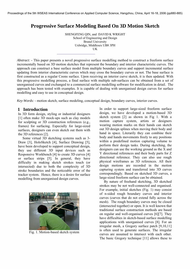
Fig. 1. Motion-based sketch system
In order to support large-sized freeform surface design, we have developed a motion-based 3D sketch system [2] as shown in Fig 1. With a motion capture system, artists or designers wearing motion marks on their hands can sketch out 3D design splines when moving their body and hand in space. Literarily they can combine their body and hands movements freely to any positions within a predefined motion capturing volume to perform their design tasks. During sketching, the designers can use the working ground as the X and Y directional references and their body parts for Z directional reference. They can also use rough physical wireframes as 3D references. All their design motions are recorded in the motion capturing system and transferred into 3D curves correspondingly. Based on sketched 3D curves, a large-sized freeform surface can be obtained. By nature of freehand sketching, 3D sketched strokes may be not well-connected and organised. For example, initial sketches (Fig. 1) may consist of n-sided rough boundary curves and interior curves (curves that do not extend fully across the mesh). The rough boundary curves may be closed (intersected together) or open. It is well known that traditional surface construction methods are based on regular and well-organised curves [6][7]. They have difficulties in sketch-based surface modelling applications with unorganised curves [8]. For an irregular mesh, a Gregory surface patch [9,10,11] is often used to generate surfaces. The irregular curves are assumed to intersect with each other. The basic Gregory technique [11] allows these to
Proceedings of the 5th WSEAS International Conference on Applied Computer Science, Hangzhou, China, April 16-18, 2006 (pp880-885)

be filled by free-from surface patches, which join together to make an over-all surface that is tangent plane continuous. However, the Gregory surface patch created is uniquely defined by the styling curves, and so there is no opportunity for a designer to locally refine the surface. From a set of unorganized curves, a surface construction technique [8] has been developed to construct a B-spline surface. It used the concept of a curve on the surface to allow a set of curves to take arbitrary orientation and possible intersect with each other. The technique searches for a global solution in the Least Square sense. The algorithm is quite complex and has difficulty in supporting interactive design and local modifications. In this paper, we present a novel surface modelling approach for supporting motion-based sketch applications in conceptual design. The approach can construct a surface model from rough boundary input and support incremental surface updating based on unorganised interior characteristic curves which may cross the boundary curves or not. Following this incremental process, a final surface with multiple sub-surfaces can be obtained and exchanged to a commercial surface modelling software for evaluation and further modifications in detail.
2 Surface Modeling Strategy From
Unorganised Curves In form design application, characteristic curves from 3D sketches are not always intersected to form a well-organised curve network. For example, lines indicating local curvatures may be drawn totally within boundary curves and without passing through them at all. Even for boundary curves, they may not form a closed curve network. In order to create a design surface from unorganised 3D sketch curves, a corresponding surface modelling strategy has been developed. It is described as follows. Firstly, identify boundary curves. Let’s say, we knew a number of arbitrary curves Ck (x, y, z), k=1,…, G. These curves can be projected onto a plane such as the XY plane and then be classified as boundary curves and interior curves by searching the furthest intersected curve with a ray line from the centroid of their projection (Fig. 2a). If the boundary curves intersect with each other, their intersection points are computed to form an exact closed boundary. If there are open gaps between two boundary curves, they will are intersected and extended in the projection plane and finally, a mid point in 3D is assigned as their common position. In
this way, a closed boundary curves can be obtained (Fig. 2b).
(a) (b) Fig. 2. Find boundary: (a) search boundary curves; (b) form a closed boundary
Secondly, create a typical 4-side boundary by combining some boundary curves together if necessary because it will make surface modelling easy. If the number of boundary curves is more than 4, let’s say L. We can merge some curves together into one composite curve. Finally, we will still have four composite boundary curves. Since each curve is input by a set of 3D points, we don’t know types of each curve and its control parameters. But we do know the sequence of points. Therefore, we can combine 3D points in order to form a new composite curve. To do so, we first compute the total chord length of each curve and then find the shortest one to be merged with its neighbouring curves. After several rounds of this merge operation, we will finally obtain two pairs of the composite curves: P(0,v) and P(1,v), and F(u,0) and F(u,1). The merge process is as follows: (1) check if the number of curves is larger than 4,
if so goes through the steps 2-4. (2) compute a total chord length for each curve. (3) find the curve with shortest chord length. (4) merge the shortest curve with one of two
neighbouring curves, which has a shorter chord length.
(5) update the number of curves and goes back to Step 1.
In this way, we can convert a N-sided interpolation into a standard four-sided interpolation. After obtaining four composite curves, we treat the curves further to make a pair of curves compatible ( having the same number of points on each curve). To do so, we first count the
Proceedings of the 5th WSEAS International Conference on Applied Computer Science, Hangzhou, China, April 16-18, 2006 (pp880-885)

number of points on paired composite curves and then insert more points on a curve with fewer points to make them equal. Each inserted points will be located at the middle of two adjacent points with the biggest chord length in each turn. Taking the drawing in Fig. 3a as an example, the five curves intersect with each other. Therefore, their intersection points are computed to form a closed boundary and the initial curves are updated correspondingly. After that, the curve B has the shortest total chord length among the 5 curves. Thus it is a candidate for a curve mergence. Its neighbouring curves C and D are then checked for a possible mergence. Because the curve C is shorter than the curve D, the curves B and C are chosen to joint together. After this mergence, the resultant composite curve is paired with the curve A. Comparing the numbers of points on the pair of curves, more points has been inserted on the curve A. Once obtaining two pairs of compatible curves, its corresponding surface can be finally generated. (a) (b) Fig. 3 boundary curves: (a) merged boundary; (b) their preimages. Finally, the four boundary curves will be mapped into a unit square in the u, v two-dimensional parameter space. The interior curves are not restricted as isoperimetric curves. Their preimages can be any 2D line segments (Fig. 3b). The details of how to obtain preimage for each interior curve is discussed in the next section. From the boundary curves, a base surface is created and then updated afterwards against each interior curve.
3 Progressive Surface Modeling This modelling process includes two phases: creating a base surface and updating it progressively from interior characteristic curves. 3.1 Creation of base surface For construction of a base surface from boundary
curves, we have chosen a bicubically blended Coons patch. In general, a Coons patch is defined by four arbitrary boundary curves: P(u,0), P(u,1) and P(0,v), P(1,v), over [ ]1,0∈u and [ ]1,0∈v , respectively. Choosing a pair of blending functions fi(u) (i=1,2) with the restrictions f1(0) =1, f1(1) =0, and f1(u) + f2(u)≡1, the general form of a Coons patch reads
[ ]⎥⎥⎥
⎦
⎤
⎢⎢⎢
⎣
⎡ −•
⎥⎥⎥
⎦
⎤
⎢⎢⎢
⎣
⎡•−−=
)()(
1
)1,1()0,1(),1()1,0()0,0(),0()1,()0,(0
)()(1),(
2
121
vfvf
ppvpppvp
upupufufvuP
(1)
Here, we choose the cubic Hermite polynomials for interpolation [9]. The blending functions are
232
231
32)(
)132()(
uuuf
uuuf
+−=
+−=
The reason for this choice is that a bicubically blended Coons patch with the above functions f1(u) and f2(u) guarantees C1 continuity between patches [9] if the boundary curves are C1 continuous. Therefore, the continuity of cross-boundary derivatives is automatically satisfied. Furthermore, the bicubic Coons patch as defined by Eq. (1) is easy to use in a design environment because only the four boundary curves are needed, although the four corners are required.
If there are 4 boundary curves, a surface from them can be generated directly with the Eq. (1). For a three-sided boundary, a surface can be generated as a special case of four sided curves. Let one of them: P(0,v), P(1,v), F(u,0) and F(u,1)has a constant position, for example, F(u,1) 1F≡ ,the corresponding surface can be gained from Eq. (1) as shown in (Fig. 4).
Fig. 4. Three-sided boundary This base surface modelling technique provides not only a capability of creating a surface from merged multiple boundary curves, but also keeps the preimage of boundary curves rectangular in the parameter space (u, v). More importantly, this will make the interior curves interpolation easier.
D
C
B A
V
U
Proceedings of the 5th WSEAS International Conference on Applied Computer Science, Hangzhou, China, April 16-18, 2006 (pp880-885)
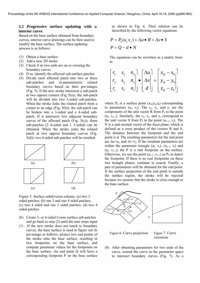
3.2 Progressive surface updating with a interior curve Based on the base surface obtained from boundary curves, interior curve drawings can be then used to modify the base surface. The surface updating process is as follows: (1) Obtain a base surface (2) Add a new 3D stroke (3) Check if its two ends are on or crossing the
boundary curves (4) If so, identify the affected sub-surface patches (5) Divide each affected patch into two or three
sub-patches and re-parameterise related boundary curves based on their pre-images (Fig. 5). If the new stroke intersects a sub-patch at two oppose corners (Fig 5(a)), the sub-patch will be divided into two 3-sided sub-patches. When the stroke links the related patch from a corner to an edge (Fig. 5(b)), the sub-patch can be broken into a 3-sided and a 4-sided sub-patch. If it intersects two adjacent boundary curves of the affected patch (Fig. 5(c)), three sub-patches (2 4-sided and 1 3-sided) can be obtained. When the stroke joins the related patch at two oppose boundary curves (Fig. 5(d)), two 4-sided sub-patches will be resulted.
(a) (b)
(c) (d)
Figure 5. Surface subdivision scheme: (a) two 3 sided patches; (b) one 3 and one 4 sided patches; (c) two 4 sided and one 3 sided patches; (d) two 4 sided patches
(6) Create 3- or 4-sided Coons surface sub-patches
and go back to step (2) until the user stops input (7) If the new stroke does not touch to boundary
curves, the base surface is used to figure out its pre-image as follows: project two end points of the stroke onto the base surface, resulting in two footpoints on the base surface, and compute parameter values for the footpoints on the base surface. An end point Q will have a corresponding footpoint P on the base surface
as shown in Fig. 6. Their relation can be described by the following vector equations.
NdQP
SvRuvuPP ji
•−=
•∆+•∆+= )( ,0
The equations can be rewritten in a matrix form as
⎥⎥⎥
⎦
⎤
⎢⎢⎢
⎣
⎡
−−−
=⎥⎥⎥
⎦
⎤
⎢⎢⎢
⎣
⎡∆∆
•⎥⎥⎥
⎦
⎤
⎢⎢⎢
⎣
⎡
0
0
0
zzyyxx
dvu
nsrnsrnsr
Q
Q
Q
zzz
yyy
xxx
where P0 is a surface point (x0,y0,z0) corresponding to parameters (ui, vj). The rx, ry, and rz are the components of the unit vector R from P0 to the point (ui, vj+1). Similarly, the sx, sy, and sz correspond to the unit vector S from P0 to the point (ui+1, vj). The N is a unit normal vector of the facet plane, which is defined as a cross product of the vectors R and S. The distance between the footpoint and the end point is d. The resulting parameters for the end point are ∆u+ui, and ∆v+vj. If the resultant parameters are within the parameter triangle (ui, vj), (ui+1, vj) and (ui, vj+1), the P is a real footpoint on the surface. Otherwise, we use the point (ui+1, vj+1) as P0 to detect the footpoint. If there is no real footpoints on these two triangle planes, continue to search. Finally, a pair of parameters will be obtained for the end point. If the surface projection of the end point is outside the surface region, the stroke will be rejected because we assume that the stroke is close enough to the base surface.
(8) After obtaining parameters for two ends of the
curve, extend the curve in the parameter space to intersect boundary curves (Fig. 7). As a
P
P0
Q
(i,j+1)
(i+1,j+1) (i+1,j)
(i,j)
Figure 6. Curve projection
G
Figure 7. Curve extension
Proceedings of the 5th WSEAS International Conference on Applied Computer Science, Hangzhou, China, April 16-18, 2006 (pp880-885)

result, we can obtain a preimage as one of the cases shown in Fig. 5. For each end, a correspond point G on the related boundary curve can be gained as well.
(9) Update the curve with extended segments. The coordinate differences between the points Q and P will be distributed to points between the Q and the correspond point G on a boundary curve.
(10) Go to Step (4) (11) When the user stops input, the resulting
surfaces from the above can be received 3.3 Creation of exchange surface The surfaces obtained from rough design sketches need to be evaluated and modified in detail. Therefore, there is a need for transferring the conceptual design surfaces into commercial CAD packages. The surface can be then further modified interactively with powerful tools for various purposes and rendered in different forms for evaluation. Currently, we create exchange surfaces for Alias Studio software through its ‘obj’ files. In order to exchange the conceptual design surfaces into the Alias Studio software, we transfer a set of u directional section curves and then create a skin surface in the Alias Studio. Of course, a set of v directional section curves will serve the same purposes as well. Each section is either interpolated or approximated by a cubic NURBS curve with a rational knot vector [11]. Once the corresponding skin surfaces are received, they can be easily modified.
(a) First update
(b) Second update Fig. 8. Surface update from section curves
4. Examples The proposed surface modelling approach and algorithm have been tested in MATLAB 5.3 with examples. Figure 8 shows an example of a surface update from section curves. The initial base surface is a flat surface. After inputting a section curve (y=20) touching on the two boundary curves, the resulting surface is shown in Fig. 8a. Then another section curve (y=40) was inputted. Consequently, the surface was updated as in Fig 8b.
Figure 9 gives another example of surface constructions from arbitrary boundary and interior curves. The initial boundary consists of 5 curves (Fig 9a): A, B, C, D, and E. The curves C and E form an open corner. These boundary curves were pre-processed with the merge of curves B and C. As a result, an initial surface interpolation from 3 boundary curves: A, D, and E and a composite curve from B and C with an open corner was conducted (Fig 9b). After that, four new closed boundary curves from the initial interpolated section curves were obtained. From them, a base surface for a Coons patch was resulted in Fig 9c. An interior stroke was then drawn over the base surface (Fig. 9d). In order to have a clear view, Fig. 9d displayed only u lines and the interior stroke. Fig 9e showed the gap between the stroke and the base surface. After identifying its projection points on the base surface, the stroke had been then extended to cross the boundary curves (Fig 9f). Correspondingly, reparameterisation had been conducted over two sub patches and the resultant surface patches are displayed in Fig 9g. The two surface patches were exchanged into the Alias Studio. Finally, a composite surface was generated as a skin surface and was rendered with some section curves (Fig 9h).
(a) (b)
( c) (d)
Proceedings of the 5th WSEAS International Conference on Applied Computer Science, Hangzhou, China, April 16-18, 2006 (pp880-885)

(d) (f)
(g) (h)
Figure 9. Surface constructions from unorganised curves: (a) 5-sided boundary with an open corner; (b) initial surface interpolation; (c) creation of a base surface; (d) input of an interior curve; (e) position of the interior curve; (f) extension of the interior curve; (g) result from reparameterisation; (h) exchange surfaces
5 Conclusion In this paper, we present a novel surface modelling approach for supporting sketch applications in conceptual design. Based on rough boundary curves with multiple curves, well-organised boundary curves are created if necessary and a corresponding base surface is then constructed based on a regular Coons patch. After that, interior design curves are incorporated to update the base surface. These interior characteristic curves may cross the boundary curves or not. In order to change the base surface from an interior curve, it is checked against the previous surface patches to figure out what patches are affected and the corresponding parameters in the parameter space. Consequently, reparameterization is conducted for refining surfaces locally. Following this incremental process, a final surface with multiple patches can be obtained and exchanged to a commercial surface modelling software for modifications in detail. The proposed surface modelling approach and algorithm has been tested with examples. It is capable of dealing with unorganised design curves for surface modelling and easy to use in conceptual design. It supports an incremental design process starting by sketching out rough boundary curves for a base surface and then refining the base surface
with interior curves. The approach can be extended for supporting a design with multiple base surfaces.
References: [1] P.A. Prieto, D.K. Wright, and S.F. Qin, A novel
method for early formal developments using CAD and RP technology. Proceedings of the Institution of Mechanical Engineering Part B, Journal of Engineering Manufacture, Vol. 217, 2003, pp. 695-698.
[2] S.F. Qin, D.K. Wright, J.S. Kang, and P.A. Prieto, Incorporating 3D body motions into large-sized freeform surface conceptual design, Biomedical Sciences Instrumentation, Vol. 439, No.1, 2005. pp.271-276.
[3] E Sachs, A Roberts, D. Stoops, 3-Draw: A tool for designing 3D shapes. IEEE Computer Graphics & Applications, Vol.11, No.6, 1991, pp.18-25.
[4] MF. Deering, HoloSketch: A virtual reality sketching/animation tool. ACM Transactions on Computer-Human Interaction Vol. 2&3, 1995, pp.220-238.
[5] S. Schkolne, M. Pruett, P. Schröder, Surface Drawing: Creating Organic 3D Shapes with the Hand and Tangible Tools. Proceedings of ACM SIGCHI’01, 2001, pp. 261-268.
[6] I. Zeid I, CAD/CAM Theory and Practice. Mc-Graw-Hill, Inc, 1991.
[7] L Piegl, W Tiller. The NURBS book. Springer, 1995.
[8] T Maekawa, KH Ko, Surface construction by fitting unorganized curves. Graphical Models, Vol. 64, 2003, pp.316-332.
[9] RA Hall, G. Mullineux, Continuity between Gregory-like patches, Computer-Aided Geometric Design, Vol. 16, 1999, pp.197-216.
[10] CCL. Wang, Parametrization ans parametric design of mannequins. Computer-Aided Design, Vol. 37, 2005, Pp.83-89.
[11] G. Mullineux Improvement of free-form surfaces for product styling applicfations. Computer-Aided Design, Vol. 34(12), 2002, pp.871-80.
Proceedings of the 5th WSEAS International Conference on Applied Computer Science, Hangzhou, China, April 16-18, 2006 (pp880-885)