siteview™ energy meter - acuity brands · 2 product description this document describes the...
TRANSCRIPT

Acuity Brands | One Lithonia Way Conyers, GA 30012 Phone: 800.535.2465 www.acuitycontrols.com © 2017 Acuity Brands Lighting, Inc. All rights reserved.
SiteView™ Energy Meter
Installation Guide

2
Product Description This document describes the installation procedures for the SiteView Energy meter. This power meter monitors the voltage, current, power, energy, and many other electrical parameters on single-phase and three-phase electrical systems. A power meter uses direct connections to each phase of the voltage, and uses Rogowski coils to monitor each phase of the current. Information on energy use, demand, power factor, line frequency, and more are derived from these voltage and current inputs. The communications interface to the meter is a RS-485 serial connection that uses the Modbus protocol for receiving commands and retrieving data.
Maintenance There is no required maintenance with the power meter. Abide by the following items:
- Cleaning: No cleaning agents, including water, should be used on the power meter.
- Battery Life: (If equipped) The lithium battery is only used to maintain the date and clock settings during power failure and has a life expectancy of greater than 10 years.
No accessories are approved for use with the power meter other than those specified in the product literature and price sheets. If the power meter appears damaged or defective, first disconnect all power and sensors. Call or email technical support for assistance.
Safety Summary and Specifications This general safety information is to be used by both the Power Meter operator and servicing personnel. Distech Controls Inc. assumes no liability for user’s failure to comply with these safety guidelines.
SVEM DISP
These items conform to the following:
Conforms to UL Std 61010-1, 3rd Edition & IEC 61010-2-030, 1st Edition Certified to CSA Std C22.2 No. 61010-1, 3rd Edition The power meter is an over-voltage Category III device. Use approved rubber gloves with mechanical protection and goggles when operating the device.
This power meter may contain life threatening voltages. Qualified personnel must disconnect all high voltage wiring before using or servicing the power meter.
Use of this device in a manner for which it is not intended may impair its means of protection.
Symbols on Equipment Certain markings (symbols) can be found on the controller and are defined as follows:
Symbol Description
Denotes caution. See manual for a description of the meanings.
When connecting the power meter to an AC load, follow these steps in sequence to prevent a shock hazard.
1. De-energize the circuit to be monitored. 2. Connect the CTs to the phases being monitored. 3. Connect the voltage leads to the different phases.
Use proper safety equipment (gloves and protective clothing) as required for the voltages monitored.
DENOTES HIGH VOLTAGE. RISK OF ELECTRICAL SHOCK. LIFE THREATENING VOLTAGES MAY BE PRESENT. QUALIFIED PERSONNEL ONLY.
Hazardous voltage exists, there are no user serviceable parts inside. Do not open the enclosure.
DO NOT EXCEED 600V. This power meter is equipped to monitor loads up to 600V. Exceeding this voltage will cause damage to the power meter and danger to the user. Always use a Potential Transformer (PT) for loads in excess of 600V. The power meter is a 600 Volt Over Voltage Category III device.
Pulse output: 30V max open voltage, 5mA max current.
SENSOR LIMITATIONS. USE ONLY SHUNTED CURRENT TRANSFORMERS (CTs). Do not use other CTs. Only use shunted CTs with a 333mV maximum output only. Serious shock hazard and logger damage can occur if unshunted CTs are used. The UL listing covers the use of the following Acuity Controls CTs that are UL Recognized and have been evaluated to IEC 61010-1: RCCT12 (Rogowski Coil) and RCCT24 (Rogowski Coil).
FCC COMPLIANCE This device has been tested and found to comply with the limits for a Class A digital device, pursuant to part 15 of the FCC Rules. These limits are designed to provide reasonable protection against harmful interference when the equipment is operated in a commercial environment. This equipment generates, uses, and can radiate radio frequency energy and, if not installed and used in accordance with the instruction manual, may cause harmful interference to radio communications. Operation of this equipment in a residential area is likely to cause harmful interference in which case the user will be required to correct the interference at user’s own expense. Operation is subject to the following two conditions: (1) This device may not cause harmful interference, and (2) this device must accept any interference received, including interference that may cause undesired operation.
Equipment protected throughout by double insulation (IEC 536 Class II).
3
Résumé de Sécurité et Spécifications Cette information de sécurité est destinée à être utilisée à la fois par l'opérateur de l'enregistreur et le personnel de service. Acuity Brands n'assume aucune responsabilité pour l'utilisateur qui ne respecte pas les directives en matière de sécurité.
PS3037-X-X Tous les articles sont conformes à ce qui suit :
Conforme à UL Std 61010-1, 3rd Edition & IEC 61010-2-030, 1st Edition Certifié CSA Std C22.2 No. 61010-1, 3rd Edition Le compteur est un appareil de surtension de catégorie III. Utiliser des gants en caoutchouc approuvé avec protection mécanique et des lunettes lors de l'utilisation de l'appareil. ATTENTION : CE COMPTEUR PEUT CONTENIR DES HAUTES TENSIONS QUI PEUVENT ÊTRE DANGEREUSES. UN PERSONNEL QUALIFIÉ DOIT DÉBRANCHER TOUS LES CÂBLES À HAUTE TENSION AVANT D’UTILISER OU DE RÉPARER LE COMPTEUR.
L'utilisation de cet appareil d'une manière pour laquelle il n'est pas destiné peut annuler ses moyens de protection.
L'utilisation de cet appareil d'une manière pour laquelle il n'est pas destiné peut annuler ses moyens de protection.
Symboles des Equipements Symbol Description
Signifie prudence. Voir le manuel pour une description de la signification.
En faisant le raccordement du compteur à une source de courant alternatif, suivez ces étapes en ordre pour empêcher un risque de choc.
1. Fermer le circuit à contrôler. 2. Connectez le TC aux phases à mesurer. 3. Connectez les fils de tension à des phases
différentes. Utiliser des équipements de sécurité (gants et des vêtements de protection) qui sont nécessaires pour les tensions surveillées.
INDIQUE HAUTE TENSION. RISQUE DE CHOC ÉLECTRIQUE. HAUTES TENSIONS PEUVENT ÊTRE PRÉSENTES QUI METTENT LA VIE EN DANGER. PERSONNEL QUALIFIÉ UNIQUEMENT.
Tension dangereuse existent, il n'y a aucune pièce réparable par l'utilisateur n'ouvrez pas le boîtier.
NE PAS DEPASSER 600V. Ce compteur peut contrôler les charges jusqu'à 600V. Le dépassement de cette tension peut causer des dommages à l'appareil et du danger pour l'utilisateur. Utiliser toujours un transformateur de potentiel (PT) pour des charges de plus de 600V. Le compteur est un appareil à 600 V de surtension de catégorie III.
Sortie d’impulsion : 30V max tension ouverte, 5 mA courant maxi. Voir l'appendice pour sortie d'impulsions l'utilisation.
Symbol Description
LIMITATIONS DE DÉTECTEUR UTILISEZ SEULEMENT TRANSFORMATEURS DE COURANT (TC) SHUNTÉE. N’utilisez pas d'autres TC. Utilisez seulement des TC shuntée avec une puissance maximale 333mV. Un sérieux risque de décharge électrique et des dommages au compteur peut se produire si des TC pas shuntée sont utilisés. La norme UL couvre l’utilisation des TC Acuity Brands suivant et ont été évalué selon la norme IEC-61010-1 : RCCT12 (Rogowski Coil) et RCCT24 (Rogowski Coil).
L'équipement protégé en double isolation (IEC 536 Classe II)
Entretien Il n'y a aucun entretien requis avec le compteur. Respectez les points suivants : Nettoyage: Aucun agents de nettoyage, y compris l'eau, doit être utilisé sur le compteur. Espérance de Vie de la Batterie : La pile au lithium est utilisée uniquement pour maintenir les paramètres de date et d'heure en cas de coupure du courant et a une espérance de vie de plus de 10 ans. Contactez Acuity Brands Instruments pour le service. Pas d'accessoires approuvés pour une utilisation avec le compteur sauf ceux spécifiés par Acuity Brands dans ses documentations sur les produits et également sur les prix. Si le compteur semble endommagé ou défectueux, tout d'abord déconnecter l'appareil de toutes sources électriques.
Dimensions
Completing the Field Installation Follow these steps to complete the field installation of your power meter: 1. Mount the power meter(s) into the electrical panel or power meter
panel. See Mounting Instructions. 2. Connect the CTs. See Wiring CTs. 3. Set the power meter’s network address. See Setting the Power
Meter’s Modbus Network Address. 4. Connect the Modbus RS-485 communications cable to the RS-485
port of the SiteView Energy meter. Set the Modbus network’s EOL terminations. See Connecting to a Network.

4
5. Connect the voltage and power the power meter through a fuse block. See Connecting Voltage.
6. Configure the power meter.
L1
L2
L3
L1
L2
L3
Power Meter Panel:Up to Two Power Meters can be Installed in One Panel
Fuse BlockElectrical Panel
Rogowski Coils X3
Figure 2: Typical Field Installation Power Wiring
Mounting Instructions The SiteView Energy meter works with Rogowski Coils located in the electrical panel. Up to two power meters can be mounted inside the power meter panel using either the mounting tabs (on either side of the power meter’s case) or the DIN rail clip. Locate the power meter panel as near as possible to the electrical panel to which the metered load is connected. The power meter requires a dedicated circuit disconnect breaker.
This power meter may contain life threatening voltages. Qualified personnel must disconnect all high voltage wiring before using or servicing the power meter.
The power meter must be installed in an approved electrical panel or enclosure using proper installation practices according to the local electrical codes.
Mounting Tab Mounting Tab
Figure 3: Power meter mounting
Wiring Connections
High voltage MAY BE PRESENT. Risk of electric shock. Life threatening voltages may be present. Qualified personnel only.
The power meter has the following connections:
- USB port for powering the power meter and communicating for advanced troubleshooting.
- A three-wire connector for the RS-485 Modbus network link. - Three CT inputs. - Four voltage connections. A fuse block is supplied to protect the
power meter. Voltage leads are customer supplied.
Figure 4: Power meter connections
Wiring CTs 1. Insert the CT wires into the connectors.
CT Type CT Lead + CT Lead - Shield
Rogowski coil* Red Black Shield
* Rogowski Coils have a shield wire which must be connected to the power meter. This reduces interference and improves accuracy of the CT.
2. Attach the CT connectors onto the power meter connections labeled CT 1, CT 2 and CT 3.
3. Place the CTs on the phase wires of the load to be monitored and corresponding to the phase of the voltage leads. The CT labeled CT 1 must be placed on L1 phase voltage wire, CT 2 must be on the L2 voltage and CT 3 on the L3 voltage. Refer to Phase Verification later in this section for information about the CT LEDs and verifying the CT installation.
The directionality for Rogowski Coils is the arrow on the label pointing toward the load.
Setting the Power Meter’s Modbus Network Address Each power meter connected to an SiteView Energy controller must have a unique network address. The valid address range for a power meter is 1 to 5.
Power Meter’s Modbus Network Address Number
Power Meter’s Address Setting
1
2
3
5
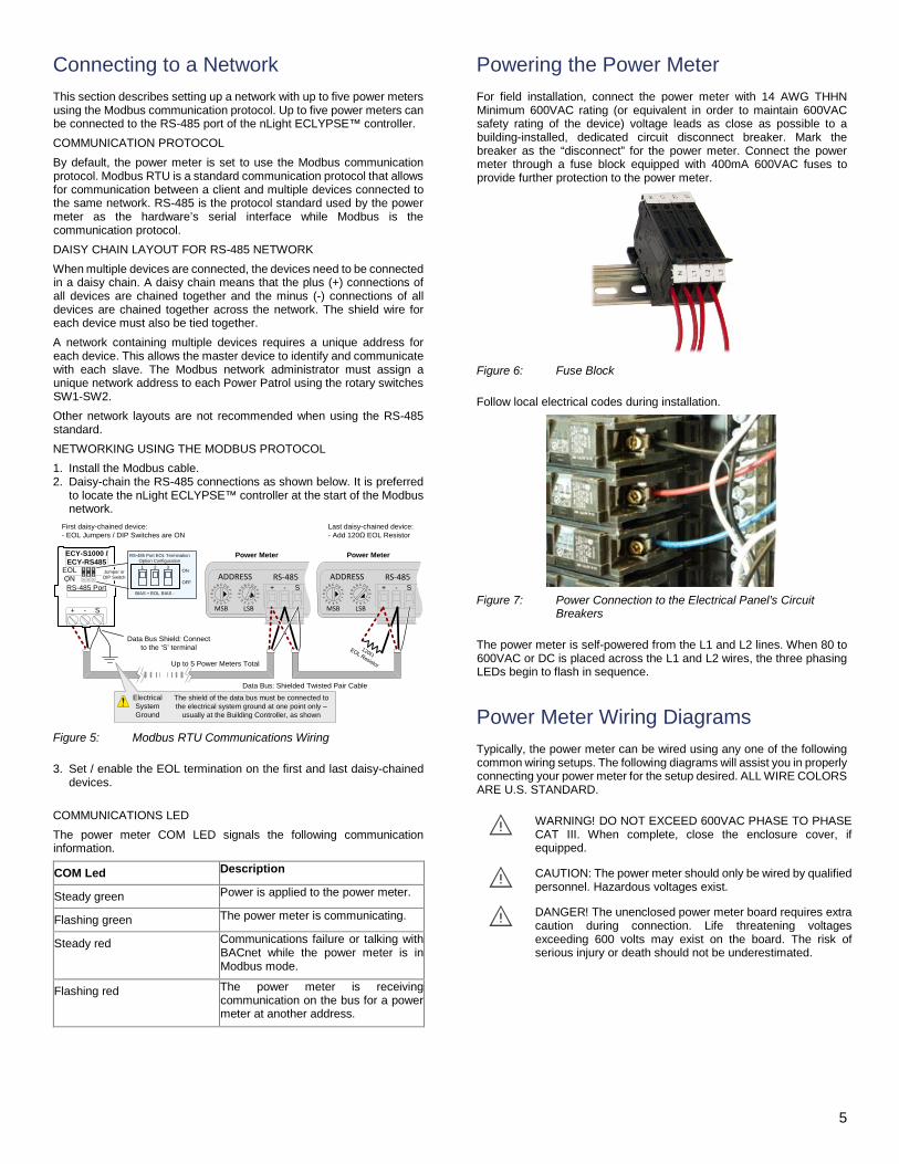
Connecting to a Network This section describes setting up a network with up to five power meters using the Modbus communication protocol. Up to five power meters can be connected to the RS-485 port of the nLight ECLYPSE™ controller. COMMUNICATION PROTOCOL By default, the power meter is set to use the Modbus communication protocol. Modbus RTU is a standard communication protocol that allows for communication between a client and multiple devices connected to the same network. RS-485 is the protocol standard used by the power meter as the hardware’s serial interface while Modbus is the communication protocol. DAISY CHAIN LAYOUT FOR RS-485 NETWORK When multiple devices are connected, the devices need to be connected in a daisy chain. A daisy chain means that the plus (+) connections of all devices are chained together and the minus (-) connections of all devices are chained together across the network. The shield wire for each device must also be tied together. A network containing multiple devices requires a unique address for each device. This allows the master device to identify and communicate with each slave. The Modbus network administrator must assign a unique network address to each Power Patrol using the rotary switches SW1-SW2. Other network layouts are not recommended when using the RS-485 standard. NETWORKING USING THE MODBUS PROTOCOL 1. Install the Modbus cable. 2. Daisy-chain the RS-485 connections as shown below. It is preferred
to locate the nLight ECLYPSE™ controller at the start of the Modbus network.
Power Meter
Data Bus: Shielded Twisted Pair Cable
Data Bus Shield: Connect to the ‘S’ terminal
-+ S
Electrical System Ground
The shield of the data bus must be connected to the electrical system ground at one point only –
usually at the Building Controller, as shown
Up to 5 Power Meters Total
-+ S
Power MeterECY-S1000 / ECY-RS485
-+ S
EOL ON
1 2 3ON
OFF
EOLBIAS + BIAS -
RS-485 Port EOL Termination Option Configuration
Jumper or DIP Switch
RS-485 Port
120ΩEOL Resistor
First daisy-chained device:- EOL Jumpers / DIP Switches are ON
Last daisy-chained device:- Add 120Ω EOL Resistor
Figure 5: Modbus RTU Communications Wiring
3. Set / enable the EOL termination on the first and last daisy-chained devices.
COMMUNICATIONS LED The power meter COM LED signals the following communication information.
COM Led Description
Steady green Power is applied to the power meter.
Flashing green The power meter is communicating.
Steady red Communications failure or talking with BACnet while the power meter is in Modbus mode.
Flashing red The power meter is receiving communication on the bus for a power meter at another address.
Powering the Power Meter For field installation, connect the power meter with 14 AWG THHN Minimum 600VAC rating (or equivalent in order to maintain 600VAC safety rating of the device) voltage leads as close as possible to a building-installed, dedicated circuit disconnect breaker. Mark the breaker as the “disconnect” for the power meter. Connect the power meter through a fuse block equipped with 400mA 600VAC fuses to provide further protection to the power meter.
Figure 6: Fuse Block
Follow local electrical codes during installation.
Figure 7: Power Connection to the Electrical Panel’s Circuit
Breakers
The power meter is self-powered from the L1 and L2 lines. When 80 to 600VAC or DC is placed across the L1 and L2 wires, the three phasing LEDs begin to flash in sequence.
Power Meter Wiring Diagrams Typically, the power meter can be wired using any one of the following common wiring setups. The following diagrams will assist you in properly connecting your power meter for the setup desired. ALL WIRE COLORS ARE U.S. STANDARD.
WARNING! DO NOT EXCEED 600VAC PHASE TO PHASE CAT III. When complete, close the enclosure cover, if equipped.
CAUTION: The power meter should only be wired by qualified personnel. Hazardous voltages exist.
DANGER! The unenclosed power meter board requires extra caution during connection. Life threatening voltages exceeding 600 volts may exist on the board. The risk of serious injury or death should not be underestimated.
6
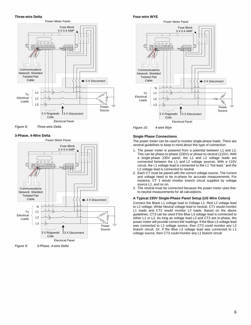
Three-wire Delta
Fuse Block3 X 0.4 AMP
L1
L2
L3
To Electrical
Loads
3 X Rogowski Coils
Power Source
3 X Disconnect
Communications Network: Shielded
Twisted Pair Cable
3 X Disconnect
Power Meter Panel
Electrical Panel Figure 8: Three-wire Delta
3-Phase, 4-Wire Delta
Power Meter Panel
Electrical Panel
Fuse Block3 X 0.4 AMP
NL1
L2
L3
To Electrical
Loads
3 X Rogowski Coils
Power Source
3 X Disconnect
Communications Network: Shielded
Twisted Pair Cable
3 X Disconnect
Figure 9: 3-Phase, 4-wire Delta
Four-wire WYE
Power Meter Panel
Electrical Panel
Fuse Block3 X 0.4 AMP
NL1
L2
L3
To Electrical
Loads
3 X Rogowski Coils
Power Source
3 X Disconnect
Communications Network: Shielded
Twisted Pair Cable
3 X Disconnect
Figure 10: 4-wire Wye
Single Phase Connections The power meter can be used to monitor single-phase loads. There are several guidelines to keep in mind about this type of connection: 1. The power meter is powered from a potential between L1 and L2.
This can be phase-to-phase (230V) or phase-to-neutral (115V). With a single-phase 230V panel, the L1 and L2 voltage leads are connected between the L1 and L2 voltage sources. With a 115V circuit, the L1 voltage lead is connected to the L1 “hot lead,” and the L2 voltage lead is connected to neutral.
2. Each CT must be paired with the correct voltage source. The current and voltage need to be in-phase for accurate measurements. For instance, CT 1 would monitor branch circuit supplied by voltage source L1, and so on.
3. The neutral must be connected because the power meter uses line-to-neutral measurements for all calculations.
A Typical 230V Single-Phase Panel Setup (US Wire Colors) Connect the Black L1 voltage lead to Voltage L1, Red L2 voltage lead to L2 voltage, White Neutral voltage lead to neutral. CT1 would monitor L1 loads and CT2 would monitor L2 loads. Based on the above guidelines, CT3 can be used if the Blue L3 voltage lead is connected to either L1 or L2. As long as voltage lead L3 and CT3 are in-phase, the power meter will provide correct kW readings. If the Blue L3 voltage lead was connected to L2 voltage source, then CT3 could monitor any L2 branch circuit. Or, if the Blue L3 voltage lead was connected to L1 voltage source, then CT3 could monitor any L1 branch circuit.
7
Power Meter Panel
Electrical Panel
Fuse Block3 X 0.4 AMP
L2
N
L1
To Electrical
Loads
2 X Rogowski Coils
Power Source
2 X Disconnect
Communications Network: Shielded
Twisted Pair Cable
2 X Disconnect
A Typical 115V Single-Phase Panel Setup Connect the Black L1 voltage lead to Voltage L1 (hot), Red L2 voltage lead to Neutral, and White N voltage lead to neutral. CT1 would monitor the L1 load. CT3 can be used if the Blue L3 voltage lead is connected to L1. CT3 could then monitor any L1 branch circuit.
Power Meter Panel
Electrical Panel
Fuse Block3 X 0.4 AMP
N
L1
To Electrical
Loads
Rogowski CoilPower Source
Disconnect
Communications Network: Shielded
Twisted Pair Cable
Disconnect
System Values System values are the sum of L1 + L2 + L3 measurements. System values may not be meaningful since two different devices or loads can be monitored by a single power meter element. When paired with the right voltage phase, each CT provides individual kW/kWh readings for that CT channel.
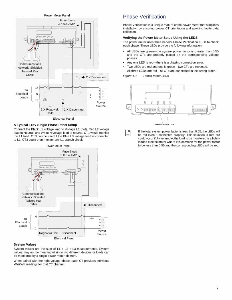
Phase Verification Phase Verification is a unique feature of the power meter that simplifies installation by ensuring proper CT orientation and avoiding faulty data collection.
Verifying the Power Meter Setup Using the LEDS The power meter uses three bi-color Phase Verification LEDs to check each phase. These LEDs provide the following information:
- All LEDs are green—the system power factor is greater than 0.55 and the CTs are properly placed on the corresponding voltage phases.
- Any one LED is red—there is a phasing connection error. - Two LEDs are red and one is green—two CTs are reversed. - All three LEDs are red—all CTs are connected in the wrong order. Figure 11: Power meter LEDs
If the total system power factor is less than 0.55, the LEDs will be red even if connected properly. This situation is rare but could occur if, for example, the load to be monitored is a lightly loaded electric motor where it is common for the power factor to be less than 0.55 and the corresponding LEDs will be red.
8 SiteView Energy_IG_10_EN_Acuity
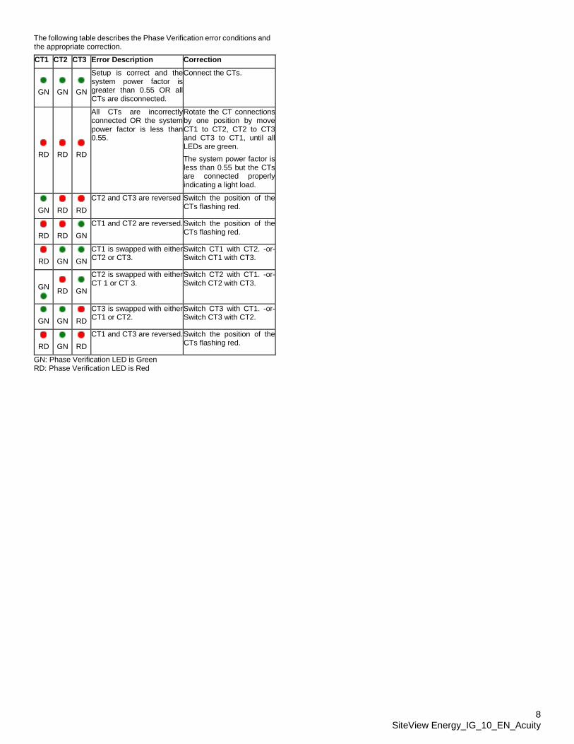
The following table describes the Phase Verification error conditions and the appropriate correction.
CT1 CT2 CT3 Error Description Correction
GN
GN
GN
Setup is correct and the system power factor is greater than 0.55 OR all CTs are disconnected.
Connect the CTs.
RD
RD
RD
All CTs are incorrectly connected OR the system power factor is less than 0.55.
Rotate the CT connections by one position by move CT1 to CT2, CT2 to CT3 and CT3 to CT1, until all LEDs are green. The system power factor is less than 0.55 but the CTs are connected properly indicating a light load.
GN
RD
RD
CT2 and CT3 are reversed Switch the position of the CTs flashing red.
RD
RD
GN
CT1 and CT2 are reversed. Switch the position of the CTs flashing red.
RD
GN
GN
CT1 is swapped with either CT2 or CT3.
Switch CT1 with CT2. -or- Switch CT1 with CT3.
GN
RD
GN
CT2 is swapped with either CT 1 or CT 3.
Switch CT2 with CT1. -or- Switch CT2 with CT3.
GN
GN
RD
CT3 is swapped with either CT1 or CT2.
Switch CT3 with CT1. -or- Switch CT3 with CT2.
RD
GN
RD
CT1 and CT3 are reversed. Switch the position of the CTs flashing red.
GN: Phase Verification LED is Green RD: Phase Verification LED is Red