site characterization plan - semspub.epa.gov · safety light corporation site characterization plan...
TRANSCRIPT

SDMSDocID 2081136
CHARACTERIZATION PLAN
SAFETY LIGHT CORPORATION SITE
BLOOMSBURG, PENNSYLVANIA
Chem-Nuclear Systems, Inc.140 Stoneridge DriveColumbia, SC 29210
December, 1991
AR100084

SAFETY LIGHT CORPORATION SITECHARACTERIZATION PLAN
TABLE OF CONTENTSSection Pace
1.0 GENERAL 1
1.1 INTRODUCTION 11.2 PURPOSE AND SCOPE 2
2.0 BACKGROUND INFORMATION 3
2.1 DESCRIPTION OF STUDY AREA 32.2 DESCRIPTION OF PRESENT ACTIVITIES 42.3 DESCRIPTION OF STUDY AREA HISTORY " 52.4 HISTORY OF WASTE HANDLING PRACTICES 6
2.4.1 SOLID WASTE MANAGEMENT 62.4.2 LIQUID WASTE MANAGEMENT 7
2.5 DESCRIPTION OF CHARACTERIZATION SITES 82.5.1 NUCLEAR BUILDING 82.5.2 GARAGE . 82.5.3 CONTAMINATED SOIL AREA IN FRONT OF ABOVE
GROUND SILO 112.5.4 METAL SILO ABOVE GROUND 112.5.5 SOLID WASTE BUILDING 112.5.6 OLD HOUSE 112.5.7 LIQUID WASTE BUILDING 122.5.8 8' x 8' BUILDING 122.5.9 UTILITY BUILDING 122.5.10 RADIUM VAULT 132.5.11 MACHINE SHOP 132.5.12 CONTAMINATED SOIL AREA NORTH OF MACHINE
SHOP 132.5.13 CONTAMINATED SOIL AREAS BETWEEN
ABANDONED CANAL AND RIVER 132.5.14 UNDERGROUND SILOS 142.5.15 EAST LAGOON 142.5.16 CARPENTER SHOP 152.5.17 WELL HOUSE 152.5.18 CESIUM ION EXCHANGE HUT 152.5.19 CONTAMINATED SOIL AREA UNDER LOADING DOCK 152.5.20 CEMENT TROUGH/SEWER GRATES BEHIND MAIN
BUILDING 162.5.21 HAND APPLICATION AREA SECOND FLOOR OF
MAIN BUILDING 162.5.22 MAIN BUILDING FIRST FLOOR 16
- i - AR100085

SAFETY LIGHT CORPORATION SITECHARACTERIZATION PLAN
TABLE OF CONTENTS(Continued)
Section Page
2.5.23 SIDEWALK AREAS 192.5.24 PERSONNEL OFFICE BUILDING 192.5.25 EAST PLANT DUMP 202.5.26 PIPE SHOP 202.5.27 WEST LAGOON 202.5.28 WEST PLANT DUMP 212.5.29 ETCHING BUILDING .' 212.5.30 DRAIN LINES 242.5.31 CONTAMINATED SOIL AREA ADJACENT TO OLD
BERWICK 242.5.32 CONTAMINATED SOIL A R E A FROM
VANCE/WALTON PROPERTY 242.5.33 CONTAMINATED SOIL AREA NORTH OF LACQUER
STORAGE BUILDING 252.5.34 ABANDONED CANAL 252.5.35 CONTAMINATED SOIL AREA SOUTH OF RADIUM
VAULT 262.5.36 CONTAMINATED SOIL AREA EAST OF THE 8' X 8'
BUILDING 272.6 SUMMARY OF PREVIOUS INVESTIGATIONS AND
CHARACTERIZATIONS 27
3.0 CHARACTERIZATION METHODOLOGIES 32
3.1 SURFACE GEOPHYSICAL SURVEYS 323.1.1 PURPOSE 323.1.2 DESCRIPTION OF EQUIPMENT 333.1.3 OPERATION OF EQUIPMENT 353.1.4 LIMITATIONS 353.1.5 DATA MANAGEMENT 35
3.2 RADIOLOGICAL SURVEYS 353.2.1 PURPOSE 353.2.2 DESCRIPTION OF EQUIPMENT 363.2.3 OPERATION OR EQUIPMENT 363.2.4 LIMITATIONS 393.2.5 DATA MANAGEMENT 40
3.3 SURFACE SOIL SAMPLING 403.3.1 PURPOSE 40
AR100086

SAFETY LIGHT CORPORATION SITECHARACTERIZATION PLAN
TABLE OF CONTENTS(Continued)
Section Page
3.3.2 DESCRIPTION OF EQUIPMENT 403.3.3 OPERATION OF EQUIPMENT 403.3.4 LIMITATIONS 413.3.5 DATA MANAGEMENT 41
3.4 DRILLING AND SUBSURFACE SOIL SAMPLING 423.4.1 PURPOSE 423.4.2 DESCRIPTION OF EQUIPMENT . . . ." 423.4.3 OPERATION OF EQUIPMENT 433.4.4 LIMITATIONS 443.4.5 DATA MANAGEMENT 45
3.5 MONITORING WELL INSTALLATION 453.5.1 PURPOSE 453.5.2 DESCRIPTION OF EQUIPMENT 463.5.3 OPERATION OF EQUIPMENT 473.5.4 LIMITATIONS 483.5.5 DATA MANAGEMENT 48
3.6 TEST TRENCH EXCAVATIONS AND SAMPLING 493.6.1 PURPOSE 493.6.2 DESCRIPTION OF EQUIPMENT 493.6.3 OPERATION OF EQUIPMENT 493.6.4 LIMITATIONS 513.6.5 DATA MANAGEMENT 51
3.7 GROUNDWATER SAMPLING 513.7.1 PURPOSE 513.7.2 DESCRIPTION OF EQUIPMENT 523.7.3 OPERATION OF EQUIPMENT 523.7.4 LIMITATIONS 533.7.5 DATA MANAGEMENT 54
3.8 SURFACE WATER SAMPLING 543.8.1 PURPOSE 543.8.2 DESCRIPTION OF EQUIPMENT 543.8.3 OPERATION OF EQUIPMENT 553.8.4 LIMITATIONS 563.8.5 DATA MANAGEMENT 56
3.9 CONCRETE/ASPHALT CORING AND SOIL SAMPLING 563.9.1 PURPOSE 563.9.2 DESCRIPTION OF EQUIPMENT 573.9.3 OPERATION OF EQUIPMENT 57
- in - AR100087

SAFETY LIGHT CORPORATION SITECHARACTERIZATION PLAN
TABLE OF CONTENTS(Continued)
Section Page
3.9.4 LIMITATIONS 573.9.5 DATA MANAGEMENT 57
4.0 PRELIMINARY ACTIVITIES 58- ...»
4.1 LICENSING 584.2 STAGING AREA/FIELD OFFICE " 584.3 STUDY AREA SURVEY 594.4 ACCESS LOGISTICS 59
5.0 LABORATORY ANALYTICAL PARAMETERS 59
5.1 RADIOLOGICAL ANALYSES 605.1.1 • RADIOLOGICAL ANALYSES PARAMETERS 605.1.2 GROUNDWATER AND SURFACE WATER
ANALYSES 615.1.3 SURFACE SOIL AND SUBSURFACE SOIL
ANALYSES 625.2 HAZARDOUS CONSTITUENT ANALYSES 66
5.2.1 HAZARDOUS CONSTITUENT ANALYSESPARAMETERS 66
5.2.2 GROUNDWATER AND SURFACE WATERANALYSES . /. 66
5.2.3 SURFACE SOIL AND SUBSURFACE SOILANALYSES 69
6.0 SITE SPECIFIC CHARACTERIZATION PLANS 77
6.1 SURFACE GEOPHYSICAL SURVEYS 776.2 RADIOLOGICAL SURVEYS 78
6.2.1 GROUND SURVEYS 786.2.2 BUILDING SURVEYS 796.2.3 BOREHOLE SURVEYS 806.2.4 TEST TRENCH SURVEYS 80
6.3 SOIL SAMPLING 816.3.1 GRID SURFACE SOIL SAMPLING 826.3.2 ABANDONED CANAL 836.3.3 EAST LAGOON 84
- iv -AR100088

SAFETY LIGHT CORPORATION SITECHARACTERIZATION PLAN
TABLE OF CONTENTS(Continued)
Section Page
6.3.4 WEST LAGOON 846.3.5 EAST AND WEST PLANT DUMPS 856.3.6 LOCALIZED CONTAMINATED SOIL AREAS 866.3.7 UNDERGROUND SILOS 876.3.8 CONTAMINATED SOIL AREAS ADJACENT TO OLD
BERWICK 886.3.9 PERSONNEL OFFICE BUILDING 7 896.3.10 PIPE SHOP 906.3.11 CONTAMINATED SOIL AREA NORTH OF LACQUER
STORAGE BUILDING . 906.3.12 LIQUID WASTE BUILDING 916.3.13 OLD HOUSE 926.3.14 DRAIN LINES (DRAINAGE DITCH FROM EAST
PLANT DUMP TO SUSQUEHANNA RIVER) 926.3.15 CONTAMINATED SOIL AREAS BETWEEN
ABANDONED CANAL AND RIVER 936.3.16 SIDEWALK AREAS 93
6.4 TEST TRENCH EXCAVATIONS AND SAMPLING 946.4.1 ABANDONED CANAL 946.4.2 EAST AND WEST PLANT DUMPS 956.4.3 UNDERGROUND SILOS 95
6.5 GROUNDWATER SAMPLING 966.6 SURFACE WATER SAMPLING 97
6.6.1 EAST LAGOON 986.6.2 WEST LAGOON 98
7.0 QUALITY ASSURANCE/QUALITY CONTROL 113
7.1 BASELINE MEASUREMENTS 1137.2 EQUIPMENT CALIBRATION 1147.3 QUALITY CONTROL SAMPLES 114
7.3.1 TRIP BLANKS 1147.3.2 FIELD BLANKS 1147.3.3 FIELD DUPLICATES 115
7.4 SAMPLE COLLECTION 1157.5 CHAIN-OF-CUSTODY 1177.6 EQUIPMENT DECONTAMINATION 1177.7 MANAGEMENT OF CHARACTERIZATION RESIDUES 118
. v - AR100089

SAFETY LIGHT CORPORATION SITECHARACTERIZATION PLAN
TABLE OF CONTENTS(Continued)
Section Page
8.0 HEALTH AND SAFETY PROCEDURES 120
9.0 CHARACTERIZATION DATA EVALUATION 122
10.0 CHARACTERIZATION PLAN IMPLEMENTATION AND COST 123
11.0 REFERENCES f 131
- vi -AR100090

SAFETY LIGHT CORPORATION SITECHARACTERIZATION PLAN
LIST OF FIGURES
Figure 1 Study Area Location Map
Figure 2 Location Map For Surface Geophysics
Figure 3 Location Map For Radiological Ground Survey and SurficialSoil Sampling
Figure 4 Location Map For Surface Soil Sampling and Deep SoilSampling
Figure5 Locat ion Map For Groundwater Sampling,Boreholes/Subsurface Soil Sampling, and ConcreteCoring/Soil Sampling
Figure 6 Location Map For Test Trench Excavations and SurfaceWater Sampling
- vn - AR100091

SAFETY LIGHT CORPORATION SITECHARACTERIZATION PLAN
LIST OF TABLES
Table 2.1 - Characterization Sites Suspected Contaminants 9
Table 2.2 - Suspected Construction Details of Underground Silos 17
Table 5.1 - US Radium Corporation and Safety Light CorporationLicensed Radioisotope Amounts 63
Table 5.2 - Radiological Laboratory Analytical Methods for Water 64
Table 5.3 - Radiological Laboratory Analytical Methods for Soil 65
Table 5.4 - Hazardous Constituent Laboratory Analytical Methods for Water . 68
Table 5.5 - Limits of Quantification for Semi-Volatile Organics 70
Table 5.6 - Limits of Quantification for Volatile Organics 73
Table 5.7 - Hazardous Constituent Laboratory Analytical Methods for Soil ... 75
Table 6.1 - Laboratory Parameter Matrix for Surface Soil Sampleswithin Grid Blocks 99
Table 6.2 - Laboratory Parameter Matrix for Surface Soil Samples 101
Table 6.3 - Laboratory Parameter Matrix for Composite Soil Samples fromTest Trenches 105
Table 6.4 - Laboratory Parameter Matrix for Deep Subsurface Soil Samples . . 106
Table 6.5 - Laboratory Parameter Matrix for Borehole Soil Samples 108
Table 6.6 - Laboratory Parameter Matrix for Soil Samples belowConcrete Cores 110
Table 6.7 - Summary of Soil Samples for Analyses 111
Table 6.8 - Monitoring Wells Scheduled for Groundwater Sampling 112
- VIM - AR100092

SAFETY LIGHT CORPORATION SITECHARACTERIZATION PLAN
LIST OF ACRONYMS
ALARA As Low As Reasonably AchievableASTM American Society of Testing MaterialsCNSI Chem-Nuclear Systems, Inc.EM ElectromagneticsEPA Environmental Protection AgencyGM Geiger MuellerGPR Ground Penetrating RadarHASP Health and Safety Planm MeterNal Sodium IodideNPDES National Pollutant Discharge Elimination SystemNRC Nuclear Regulatory CommissionORAL) Oak Ridge Associated UniversitiesPVC Polyvinyl ChlorideRCS Radiation Control SupervisorRMC Radiation Management CorporationSLC Safety Light CorporationTCLP Toxicity Characteristic Leaching ProcedureUSR United States RadiumUSRC United States Radium Corporation
- ix - AR100093

1.0 GENERAL
1.1 INTRODUCTION
The study area is owned and operated by the Safety Light Corporation
(SLC) to manufacture radioactive (tritium) products (ie, self illuminating
light sources, etc.) under a Nuclear Regulatory Commission (NRC) License,
No. 37-00030-08, and is located east of the city of Bloomsburg,
Pennsylvania. Both United States Radium (USR) Metals, Inc. and
Multimetals Products Corporation lease portions of the study area to
manufacture nonradioactive products. The majority of the study area
including grounds and structures were, in the past, us"ed for manufacturing
radioactive products or have the potential to contain radioactive
contamination from past production/disposal activities. Therefore, the
study area includes all portions of the SLC property (see Figure 1).
SLC production areas lie within the radiological restricted area and are
enclosed by a security fence. SLC also owns the property southeast of the
study area adjacent to the Susquehanna River hereafter referred to as the
Vance /Walton property.
Operations which took place in the late 1940's, 1950's and 1960's under
previous owners involved the use of Carbon-14 (UC), lron-55 (55Fe),
Cobolt-60 ("'Co), Strontium-90 (^Sr), Americium-241 (241Am),
Cesium-137 (137Cs), Radium-226 (22eRa), and other radionuclides (Berger,
1982). Although some attempts at decontamination of selected parts of
this study area were made in the 1970's, residual contamination, due to
past practices, remain. Monitoring data shows that soils beneath the
study area are contaminated with 22eRa, Tritium (3H), Sr, and 137Cs and
shallow groundwaters are contaminated with 3H and "Sr (NRC, 1988 and
CNSI, 1990).
- 1 -AR100094

Soil and groundwater contamination appear to have been caused by
disposal of radioactive waste and effluents. Site operators have discarded
both radioactive and chemical wastes at the study area. The site operators
have made numerous changes to the waste disposal and operation
practices in response to directions from regulatory agencies.
Attempts at mitigating site contamination were made by US Radium
Corporation (USRC), a previous owner of the study area, however, this
program was not completed. Therefore, a considerable section of the
study area remains contaminated with both radiological and hazardous
constituents.
1.2 PURPOSE AND SCOPE
This Characterization Plan has been developed in response to SLC's and
USR's request in response to the NRC's regulatory directives. The "Order
Modifying Licenses (effective immediately) and Demand for Information"
also referred to as the March 1989 Order, instructs the licensee to:
"describe in detail how a complete radiological and
geohydrological survey of all facilities and the surrounding surface
and subsurface soil and groundwater will be conducted in order
to fully determine the radionuclide concentrations and their lateral
and depth profiles, as well as their movement in the groundwater
and soil. The surveys shall be sufficient to develop a complete
plan for decontamination/removal operations necessary to permit
unrestricted access to site. The plan shall include, but not be
limited to, provisions to address the issues contained in the NRC
Environmental Evaluation of the Safety Light Corporation Site,
Bloomsburg, Pennsylvania (NRC-88). Particular attention shall be
given to identifying areas of the site that should be given priority
in the site decontamination activities" (NRC, 1989).
- 2 - AR100095

This Characterization Plan addresses characterization of surface and
subsurface soils, ground water, surface water, and study area structures.
In addition, this plan incorporates relevant aspects of the "NRC Staff's
Response to Licensing Board's Questions Expressed During Conference of
April 19, 1991."
The objective of this Characterization Plan is to provide an orderly cost-
effective and technically sound characterization of the study area, so when
completed, remediation technologies and costs can be developed for
specific areas within the study area, or combined as a whole. Then
site-specific remediation activities can be initiated, with the approval of
SLC, USR Industries, and the NRC.
2.0 BACKGROUND INFORMATION
2.1 DESCRIPTION OF STUDY AREA
The study area, contains approximately 10 acres (see Figure 1). Of this
area, SLC occupies approximately 2 acres. Portions of the remaining area
are leased to USR Metals, Inc. and Multimetals Products Corporation. The
study area lies within the South Central Township in Columbia County,
approximately 6 miles east of Bloomsburg, Pennsylvania. The study area
is bound on the north by Old Berwick Road (previously Route 11) and on
the south by the Susquehanna River. The Vance/Walton property located
along the southeast corner of the study area is owned by SLC. Other
residential tracts of land are adjacent to the east and west boundaries of
the study area.
Of the three companies located on the study area, only SLC currently uses
radioactive materials (3H) in their production activities. USR Metals, Inc.
and Multimetals Products Corporation do not use radioactive materials in
their production activities, however the areas leased and occupied by both
- 3 -AR100096

companies, was at one time associated with the production of radioactive
products and the use of radioactive materials. Therefore, the entire 10
acres are included in the study area. In the event, during characterization
activities, preliminary data indicates the need to conduct expanded
characterization activities in areas outside the study area, then an
amendment to this plan will be developed including scope-of-work,
permission for access, and costs.
2.2 DESCRIPTION OF PRESENT ACTIVITIES
SLC manufactures and distributes a variety of products which use 3H. The
principal products include self-luminous safety devices for use in
commercial/military aircraft, commercial buildings, and the marking of
aircraft and helicopter landing areas; research and development operations
for military and industrial applications; titanium tritide-coated rods and pins
for use in military and industrial type electron tubes; and 3H targets for use
in neutron generating devices. All production, handling, and storage
activities are located within a fenced restricted area.
USR Metals, Inc. leases areas within the study area, and conducts non-
radioactive operations involving the manufacture of dials, nameplates, and
other specialty products used in a variety of military and industrial
applications.
Multimetals Products Corporation leases areas within the study area, and
is involved in non-radioactive operations including anodizing of aluminum
products, and application of specialty protective films to the surfaces of
various metal items.
- 4 - AR100097

2.3 DESCRIPTION OF STUDY AREA HISTORY
During World War II and prior to occupation by USRC, the study area was
used to manufacture wooden toys (NRC, 1988). Radioactive operations
began at the plant site in 1948-49, with the relocation of USRC's radium
operations from Brooklyn to the Bloomsburg site. The radioisotopes in use
at that time were primarily 226Ra, and minor amounts of Polonium-210
(210Po). During the early 1950's, the expansion of USRC's radioactive
products included civil defense check sources and radiation sources
utilizing 137Cs in large quantities. Project F in the same time period resulted
in the production of approximately 500,000 deck markers for the U.S.
Navy involving an extensive ^Sr production line. 226Ra was being used
during this same time period primarily for clock and watch dials and hands;
however, radium rope and high level neutron and radiation therapy sources
were also being manufactured.
When other radioisotopes became available, at a later time period, the
research and development group carried out development work with
approximately 20 different radioisotopes. Although most radioisotopes
were handled only in small quantities, several became major sources of
revenue for the company. Tritium, 14C, and Thallium-204 (204TI), were
used for light sources; Nickel-63 (MNi) and 3H were developed for low-level
ionization sources; Krypton-85 (8sKr) was utilized, for light sources,
radiation sources, and for beta sources. In the early 60's work began with
Americium-241 (241Am), a replacement for 228Ra, in certain applications.
In 1968, USRC decided to discontinue all operations with 22eRa. In 1969,
all radioisotope business, except the 3H business, was sold. At this time,
the Nuclear Building, was erected to house the 3H production operation.
From this time on (July, 1969) the only radioisotope handled in production
has been 3H and all radioactive operations have been carried out in the
Nuclear Building (USRC, date unknown).
- 5 -AR100098

Throughout the site operational history various solvents and other chemical
agents were used to support operations including ethylene glycol, acetone,
and toluene.
2.4 HISTORY OF WASTE HANDLING PRACTICES
Throughout the-history of the~study area, during the periodfrom 1948 to
date7waste pfoductsrincluding solid and liquid waste, have been disposed
6Tby~various~means~ Although there does not appear to be any detailed
documentation concerning waste management practices, a comprehensive
review of available records does reveal a general understanding related to
how thes~e"Waste forms were handled.~\
2.4.1 SOLID WASTE MANAGEMENT
There is a lack of documentation concerning solid waste
management during the period from 1948 to 1950. There is)
howeverTlpeculation'that trTe"West Plant Dump was used cfiirihg
thisl>eriqd. cA^portioTTartheicanaJ was used to dispose of 226Ra
cContaminatedTJuct work earlyjn the:study:aTea:rTist6ry\^The Pipe
Shop was constructed over this filled portion of the Abandoned
Canal (Brown, 1979). During the period from 1950 to 1960,
solid waste was disposed of in the two buried Underground Silos,
as supported by documented interviews (Brown, 1979).
Following the closure of the silos, radioactive solid waste was
shipped off-site for disposal at approved low-level radioactive
disposal facilities. This practice continues to date. During 1971
amO 972712;OOCTpounds:pf isoil contaminated with 226Ra was
removed from the West Plant Dump area a_nd_shippedoftsite for
disposal?
- 6 - AR100099

2.4.2 LIQUID WASTE MANAGEMENT
Again, the early period of the study area history lacks
documentation concerning the method of liquid waste
management. (Internal rnemprandumsjand[laboratory notes from J
,_ indicate that_a!L liquid!?
<waste _f torn radioactive production activities were routed tp_qpejy
portions of the^anal. The major radioisotopes noted were 137Cs,
"Sr, and 226Ra. It appears that USRC decided to change liquid
waste handling practices due to the observed levels of radioactive
contamination in the canal. In the 1960 notes from Allam, plans
were being made to route all liquid effluents from the production
building to a holding tank and then to an evaporator. In
conjunction with this change, plans were made to precipitate out
the radioactive constituents in the canal water and discharge the
treated water to the Susquehanna River.(
{"sediments in the^ canalI vyerejtien to be excavated and disposed
r(Allam, 1960). Other documentation indicated this was done,
rhoweveri-the degree-of decontamination is uTriknown (Browrv
fT97fj],. /
Around 1960, a holding tank and evaporator was constructed in
the location of the Liquid Waste Building. The holding tank and
evaporator were constructed below grade and during 1972 the
Susquehanna River flooded the study area. The 1972 flood
destroyed the holding tank/evaporatorsystem. Subsequently, the
below grade structure was filled in and the present Liquid Waste
Building was constructed over this location.
During the period of 1972 to date, liquid effluents from the 3H
processing area are collected in above ground holding tanks in the
Liquid Waste Building. Upon 3H analyses and proper dilution the
-7 -AR100100

liquid effluent is discharged to the Susquehanna River in
accordance with the conditions of Environmental Protection
Agency (EPA) National Pollutant Discharge Elimination System
(NPDES) Permit No. 0111848. Presently, liquid scintillation
solutions are concentrated by evaporation and the dry residues
are shipped off-site for disposal at an approved low-level
radioactive disposal facility (SLC, 1981).
rSanitarywastes were, aToneTime^ discharged to the open canal,
fhoweverrthis practice was discontinued and sanitary wastes are
rcurrently routed~to~a~septic tank.
2.5 DESCRIPTION OF CHARACTERIZATION SITES
Thirty-five individual sites have been identified for characterization within
the study area. The locations of the sites are shown on Figure 1. The
description of the sites is presented below and a summary of the
suspected contaminants at each site is shown on Table 2.1. The site
specific characterization plans are described in Section 6.0.
2.5.1 NUCLEAR BUILDING
The Nuclear Building has been in operation since 1969 for the
production of tritium light sources. The only suspected
contaminant is 3H.
2.5.2 GARAGE
The Garage was originally used for the storage of radioactive
materials prior to 1950. The structure has been removed and a
partial cement foundation remains, approximately 20' x 12'. The
soil under the Garage is suspected to be contaminated with "Sr,226Ra, 137Cs, and 210Po.
- 8 - AR100101

TABLE 2.1CHARACTERIZATION SITES SUSPECTED CONTAMINANTS
SUSPECTED OMTANIgAlfTS
Study ATM Site
Nuclear Building
Garage
Contaminated Soil Area inf — :t of Above Ground Silo(' :Metal Si lo Above Ground
Solid Waste Building
Old House
Liquid Waste Building
8' x 8' Building
Utility Building
Radium Vault
Machine Shop
Contaminated Soil Area Northof Machine Shop
Cant MB! na ted Soil Areasbetween Abandoned Canal andRiveri1 -ground Silos
East Lagoon
Carpenter Shop
Well Mouse
Cesium Ion-Exchange Hut
Contaminated Soil Area underLoading Dock
Cement Trough/Sewer Grate(Behind Main Building)
3H
•
•
•
•
•
•
•
•
14C "Co
•
•
•
«NI
• •
•
•
"Sr
* •
•
•
•
•
•
•
•
•
•
1HCs
•
• .
*
•
•
•
•
•
ao4n "?Ac "7Np M1Am
•
•
•
"*Ra
•
•
•
•
•
•
•
•
•
•
•
•
•
Metals
*
•
*
Cyanide Solvents
•
•
•
Petrol eonHydrocarbons Radon
•
- 9 -AR100102

TABL£ 2.1CHARACTERIZATION SITES SUSPECTED CONTAMINANTS
(Continued)
Main Building
Sidewalk Areas
F -noel Office Building
East Plant Dump
Pipe Shop
Uest Lagoon
Uest Plant Dump
Etching Building
Drain Lines
Contaminated Soil AreaAdjacent to Old Berwick Road
Contaminated Soil Area FromVance/Walton Property
Contaminated Soil Area Northof Lacquer Storage Building
/;'"• ximate location ofAt .-Joned Canal
Contaminated Soil Area Southof Radium Vault
Contaminated Soil Area Eastof 8' x 8' Building
3H
•
•
•
•
•
•
MC
•
•
"Co
•
•
•
"Mi
•
•
•
"sr
•
t•
•
•
•
•
'"Cs
•
•
-
•
•
•
»«Tl
•
•
•
M7Ac "7Mp J41An,
•
•
•
"aRa
•
•
•
•
•
•
•
•
•
•
•
Metals
•
•
•
Cyanide
•
•
Solvents
•
PetroleunHydrocarbons
*
Radon
•
•
- 10-AR100103

2.5.3 CONTAMINATED SOIL AREA IN FRONT OF ABOVE GROUNDSILO
A small area of contaminated soil exists southwest of the Garage
and in front of the Above Ground Silo. The contamination is
believed to have resulted from a spill of 137Cs.
2.5.4 METAL SILO ABOVE GROUND
The Metal Silo Above Ground was used for the storage of 22eRa
ionitrons. The Metal Silo is currently used for the storage of 3H
contaminated equipment (approximately 25% storage capacity).
The Metal Silo is approximately 5' in diameter and is sitting on a
degrading cement foundation. The circular fence enclosure has
been removed. The silo and underlying soil are suspected of
being contaminated with 3H and 226Ra.
2.5.5 SOLID WASTE BUILDING
The Solid Waste Building is currently used for the storage and
compaction of low-level radioactive waste. The building is
vented routinely to reduce 3H activity. Miscellaneous pieces of
equipment including an old evaporator and empty drums are
stored behind the building. The suspected contaminants inside
the building are 3H, ^Sr, 2MRa, "Co, 137Cs, 86Kr, a3Ni, 210Po, and241Am.
(2.5.6 OLD HOUSED
<The Old House is an 1800's residential 2istorywood~hl>uslfwith
a dug-out earthen basement. The interior of the Old HouseJs in
pdoTstructural"condition.L_The. first floor is currentlyjjsedjgrthe/
^storage of contaminated equipment_(apprpximalely~95 %'l;torag3
^capacity). The second floorjs usedjor storagejol^contaminated
^records~and supplies—The-suspected-contaminant-is-22eRaT—1
- 11 -AR100104

2.5.7 LIQUID WASTE BUILDING
Before 1960, the Liquid Waste Building site contained
below-ground vaults used to dilute low-level radioactive waste
water from the Main Building and Etching Building prior to
discharge to the river. After the 1972 flood, the vaults were
capped and the Liquid Waste Building was built over the vaults.
The Liquid Waste Building is currently used for the dilution of
low-level radioactive waste water from the Nuclear Building. The
waste water is transported by a below grade drain line to a below
grade concrete sump within the Liquid Waste Building. The
waste water is pumped from the sump to" one of four 2,400
gallon above ground dilution tanks. The diluted waste water is
discharged to the river through NPDES Discharge Outfall #1,
Permit No. 0111848. (The waste water discharge does not
contain any radioisotopes other than tritium.) The Liquid Waste
Building has been noted to contain elevated radon
concentrations. The suspected contaminants in the building and
surrounding area are 3H, 137Cs, 226Ra, "Sr, "Co, 86Kr, 63Ni, 210Po,241 Am, radon, ethylene glycol and acetone.
2.5.8 8' x 8' BUILDING
The 8' x 8' Building was used for the storage of °°Sr deck
markers. The building is currently used for the storage of 3H
contaminated equipment. A small localized area of contaminated
soil is present in front of the building. The suspected
contaminants are KSr and 3H.
2.5.9 UTILITY BUILDING
The Utility Building was used for the storage of "Sr solution and
was formerly referred to as the TOSr Vault. The building has been
partially decontaminated and is currently used for the storage of
- 12- AR100105

non-radioactive materials and supplies (approximately 60%
storage capacity). The suspected contaminant is ^Sr.
2.5.10- RADIUM-VAULT
ThejIRadium Vault-was used for the pouringlQLlead-and-the
storage-of.radium foils.^ AH radioactive matenalslifeIrTought to
have been removedJrom the building^ Thejoof structure of the
, building has collapsed, thereby inhibitingI entry into'Jjie buildijTg.
The-suspected contaminants are 228Ra and lead.
2.5.11 MACHINE SHOP
In the early 60's this building was referred to as the Tritium
Building and used for the manufacturing and/or handling of tritium
foils and tritium luminous compounds. In 1969, the tritium
production operations were moved to the Nuclear Building
allowing partial decontamination of the building. The building is
currently used as a Machine Shop involving non-radioactive
materials. Contamination is known or suspected to remain in the
overhead ventilation lines, exhaust fan, and under the pavement
adjacent to the building. The suspected contaminants are 3H and
toluene.
2.5.12 CONTAMINATED SOIL AREA NORTH OF MACHINE SHOP
The contaminated soil area is a small localized area of surface
contamination which may have resulted from traffic from the old
Radium Laboratory (see Section 2.5.22). The suspected
contaminant is 226Ra.
2.5.13 CONTAMINATED SOIL AREAS BETWEEN ABANDONED CANAL
AND RIVER
- 13-AR100106

A large area of contaminated soil exists along the southern
boundary of the SLC property between the Abandoned Canal and
river. The soil contamination is suspected to have resulted from
the transfer of contaminants from other sites (East and West
Lagoons, East and West Plant Dumps, etc.) during the 1972
flood. The area is completely covered with heavy undergrowth.
The suspected contaminants are 3H, 137Cs, 226Ra, and ^Sr.
2.5.14 UNDERGROUND SILOS
Two Underground Silos were used for the disposal of solid
radioactive waste between 1950 and 1960. Silo #1 was used
between 1950 and 1952 for the disposal of 226Ra and "Sr, and
possibly 137Cs. Silo #2 was used between 1952 and 1960 for
the disposal of ^Sr and 137Cs, and possibly 22aRa. The
construction details of the silos are contained in Table 2.2. The
silo area is currently covered with grass and is enclosed by a
fence.
2.5.15 EAST LAGOON
The East Lagoon is an unlined earthen surface impoundment with
two visible influent drain lines. Between 1948 and 1954 the East
Lagoon was used for the disposal of sewage and process waste
water from the old Radium Laboratory in the Main Building.
Precipitation was conducted in the lagoon in the early 1960's
(see Section 2.4.2). The lagoon was flooded in 1972 and is
believed to have contributed to contamination of the surrounding
soils. The East and West Lagoons are the remaining portions of
the Abandoned Canal. The East Lagoon is currently used for
disposal of overflow sewage and stormwater. The suspected
contaminants are 3H, wSr, 228Ra, "Co, 137Cs, 86Kr, 63Ni, 210Po, and241Am.
- 14-AR100107

2.5.16 CARPENTER SHOP
The Carpenter Shop also referred to as the Old Maintenance Shop
is now used for the storage of contaminated equipment and
supplies. There is localized contamination on the east wall of the
building which resulted from the explosion of a Sr source. The
suspected contaminant is MSr.
i2757T7~WELTTl6uSE
The north end of the Well House contains the old water supply
well (Monitoring Weir 17). The south end of the Well House was
referred to as the! Adhesive Lab and was used for the formulation
of adhesives. The south end was decontaminated in 1958 and
is currently used for the storage of shredded packing paper.(the
suspected contaminants are 226Ra and solvents.
2.5.18 CESIUM ION EXCHANGE HUT
The Cesium Ion Exchange Hut once housed cesium ion exchange
systems used for the treatment of waste water from the Cesium
Laboratory in the Main Building. The Cesium Ion Exchange Hut
has been gutted, however, contamination remains on the wall
surfaces and floor. The suspected contaminant is 137Cs.
2.5.19 CONTAMINATED SOIL AREA UNDER LOADING DOCK
The loading dock was used as a porch for the entrance and exit
to the former Radium Laboratory located in the Main Building.
Through the years of operations the soil underlying the loadingi
dock has become contaminated as a result of the traffic from the
former Radium Laboratory. The soil underneath the pavement
adjacent to the loading dock may also be contaminated. The
loading dock is currently used as a passage way to dispose of
paper and metal wastes by Multimetals and USR Metals
- 15 -AR100108

custodians. The suspected contaminants are 226Ra, heavy
metals, and solvents.
2.5.20 CEMENT TROUGH/SEWER GRATES BEHIND MAIN BUILDING
The Cement Trough/Sewer Grates were part of the drain
conveyance which transported radioactive process waste water
from the Main Building to the East Lagoon. The suspected
contaminants are 22eRa and
2.5.21 HAND APPLICATION AREA SECOND FLOOR OF MAIN BUILDING
The Hand Application Area was used for hand painting using22eRa and 3H until July 1969 (USRC, 1978). The area was
partially decontaminated in 1968, however, contamination
remains in the attic, ductwork and rafters. The area is currently
used for storage of contaminated and uncontaminated records
and supplies. The suspected contaminants are 220Ra and 3H.
2.5.22 MAIN BUILDING FIRST FLOOR
The Main Building has undergone several structural expansions in
its history. The original building which currently houses the SLC
administrative offices (first floor only), contained 8,000 ft2 on the
first floor, 5,000 ft2 on the second floor, and a 600 ft2 lunch
room on the third floor. In this original building, 226Ra and 3H was
handled on the east half of the second floor where 3H and 22eRa
painting operations took place. In 1969, Safety Light contracted
a vendor to perform decontamination operations in the Main
Building and on the roof, which was accomplished to the degree
necessary to allow unrestricted access to all three floors of the
Main Building.
- 1 6 -AR100109

TABLE 2.2
SUSPECTED CONSTRUCTION DETAILS OF UNDERGROUND SILOS1
1Diameter (in feet)
Depth (in feet)
Volume (cubic feet)
Construction Material (ininches)
Date Constructed
Date Closed
MSr
"8Ra
117Cs
water level (in feet bis)
SILO NO. 1
10-12
15
1178-1697
3/1 6 steel cylinder
1950
1952
small quantities
large quantities
possibly
11-16
SILO NO. 2
10-12
15
1178-1697
3/1 6 steel cylinder
1952
after 1960
large quantities
possibly
small quantitiesi-
11-16
1 Brown, 1979
bis (below land surface)
- 17 -AR100110

Some time in the late 1940's, a one story addition was added
south of the three story main structure and east of the
mechanical application room. This addition added about 14,000
ft2. Sometime between the late 1940's and 1959, a one story
2,000 ft2 expansion was added to the east side of the 14,000 ft2
expansion. Currently the Main Building encompasses about
30,000 ft2.
About 5,000 ft2 of the first floor of the original Main Building has
been extensively renovated and now houses offices for SLC and
USR Metals. For the most part, the remaining 3,000 ft2 of the
original Main Building, first floor, is utilized by SLC for
non-radioactive processes. The one story, 14,000 ft2 addition is
also currently used by SLC for certain non-radioactive processes.
The 2,000 ft2 addition on the east side of the Main Building is
utilized primarily for storage.
The second and third floors of the Main Building are inactive.
The east half of the second floor is used for document and
equipment storage while the west half is predominantly as it
existed during former 3H and 228Ra work. The third floor lunch
room is empty. :
As previously stated, the original 3H and 228Ra dial paintings were
performed in the Main Building. Although free access is possible
in these areas, the potential exists for contamination in normally
inaccessible areas, areas which have been recovered, or areas
which are currently being used for non-radioactive processes.
(For example, the linoleum floor on the second floor is not original
and no surveys exist to document that the underflooring is
uncontaminated.)
- 18-AR100111

As operations were relocated to the 14,000 and 2,000 ft2
additions, radioactive work took place in certain portions of these
additions. Other isotopes were being handled in these additional
areas including ^Sr, 137Cs, 14C, ^Tl, Promethium-147 (U7Pm),60Co, 85Kr, 210Po, and 63Ni. As radioactive processes were
discontinued in these additions and moved to the Nuclear
Building, decontamination efforts were performed to the point
where unrestricted access was permitted by the on-site health
physics group. Over time, other equipment and support systems
were installed in these released areas, which are still in use
today. The suspected contaminants are ^Sr, 137Cs, 14C, 20*TI,147Pm, ^Co, 86Kr, 210Po, 63Ni, 226Ra, 3H, and radon.
2.5.23 SIDEWALK AREAS
The exterior sidewalks provide access primarily to the Main
Building. The Main Building is now used as an administration
building; however, it was previously used for radioactive material
processing. Traffic into and out of the Main Building is suspected
to have spread contamination to the sidewalks and adjacent soils.
The suspected contaminant is 220Ra.
(2.5724" PERSONNEL OFFICE BUILDING
The Personnel Office Building is one-story with a belowHgfade>
cellar which can be accessed from an external trap door. A 2'-
diameter hexagonal shaped concrete slab is located on tHe floor
of the cellar directly beneath the trap door The_slab_is_2" Jhick
and appears to have been poured in place. ";
The Personnel Office Building was used as administrative p_ffice
space and storage for 226Ra, ^ST^screenjng, machines,Zand/
strontiurrr chloride (Brown, 1979)7lt~is~"suspected^fhat'
- 19-AR100112

radioactive waste, was disposed in -a "dry well"-Jocated in-the
.below grade cellar of the building; however, there is, no known
record of such waste disposal. Reference to the disposahof
radioactive waste into _a "dry weH" may have been made referring
to the Undergroud Silos instead of the location of the Personnel
Office Building. The concrete slab is suspected to be covering
the "dry wellX The building is currently in poor structural
condition and is used for storage of miscellaneous radioactive and
non-radioactive items (approximately 40% storage capacity). The
suspected contaminants are 22eRa
2.5.25 EAST PLANT DUMP
The East Plant Dump is located between the East and West
Lagoons. This dump was used prior to the 1970's for disposal
of radioactive waste. The proximity of the East Plant Dump to
the East and West Lagoons suggests that it may have been part
of the Abandoned Canal. The suspected contaminant is ^Sr.
2.5.26 PIPE^SHQP
The~site^now occupied-by-the Pipe Shop, ~was used ir[ 1 948 for
the disposal of~raclium~contaminated ductwork from the USRC
Brooklyn, jsiew York facility. The building, then referred to as the
Maintenance Shop, was built over the disposal area. The
Maintenance Shop was used for maintenance and lead melting.
The building is how referred to as the Pipe Shop and is used for
the storage of-H screening machirfesT paintinytablelTirnd lead
,meltihg_potsT The" Pipe Shop is ventilated routrnely~to~reduce
radon concenfratiohsT The suspected contaminants are 226Ra, fH,
Radpn^and, le_ad.
2.5.27 WEST LAGOON
- 2 0 -AR100113

The West Lagoon is an unlined earthen surface impoundment.
The West Lagoon was used in the 1950's and 1960's for the
disposal of non-radioactive silver plating waste and anodizing
solutions from the Etching Building. In the 1960's the contents
of the East Lagoon was pumped one time into the West Lagoon,
thereby introducing radioactive contaminants. The lagoon was
flooded in 1972 and is believed to have contributed to
contamination of the surrounding soils. The West and East
Lagoons are the remaining portions of the Abandoned Canal. The
West Lagoon is currently abandoned. The suspected
contaminants are "Sr, 226Ra, 3H, "'Co, 13?Cs, 85Kr, 83Ni, 210Po,241Am, metals, cyanide and acids.
2.5.28 WEST PLANT DUMP
The West Plant Dump area was previously used for the disposal
of solid radioactive waste such as 226Ra dials and °°Sr deck
markers. In the 1970's the area was partially excavated and
approximately 78 drums of solid waste were filled and sent off-
site for disposal. The proximity of the West Plant Dump to the
West Lagoon suggests that it may have been part of the
Abandoned Canal. The dimensions of the area are approximately
40' x 50'. Currently, miscellaneous trash and drums are
exposed. The suspected contaminants are 226Ra and ^Sr.
2.5.29—ET_C_HING_ BUILDING
i v. The original Etching Building was constructed in~T94^--~a~nds
' consisted of approximately 16,025 ft-,-with_an additional 350 ft2
separate Radium Measuring Building. The Radium Measuringt '
• Building does not currently exist;_asa separate^Wuc^tlireT It was
xi located where the Carpenter ;j3hpp Ts now located Jn the Etching
Building. Between 1949 and 1976 thOtc^ing~Building-was
- 21 -AR100114

expanded to its current 32,000 ft2. This does not include a
6,000 ft2 manufacturing addition built in 1974 on the
northernmost end of the Etching Building. No radioactive
materials have been utilized in this building; therefore, it should
not require investigation or assessment. However, the ground
below this addition, particularly that area on the south end of the
addition which adjoins the original Etching Building structure, may
contain surface or subsurface contamination.
Many different activities took place in this building. However,
the primary radioactive processes involved the assembly and
manufacture of radium and tritium instruments, dials, etc. Some
areas of the building were used for support services such as
silver plating, chemical storage, maintenance activities, machining
tool and die, and office space. Depending on the radiological
controls practices used at the time (including decontamination
criteria), these support areas could contain low to moderate
amounts of contamination. Areas where tritium and radium were
handled and little or no decontamination efforts have been
undertaken, represent the areas of highest potential for
contamination. The Tritium Screening Room area is recognized
as the area containing the highest potential for contamination in
the building.
At present, approximately 25% of the Etching Building is leased
to USR Metals. This leased space has been extensively
renovated and is located on the east side of the building. SLC
utilizes about 1,600 ft2 on the north end of the building for
assembly of non-radioactive components for exit signs. Portions
of the remaining floor space, primarily on the south end, are used
for storage of various chemicals, supplies, and materials.
- 2 2 -AR100115

nApproximately 50% of the floor space is inactive and generally
in a fair to poor state of order and cleanliness. Except for the
Tritium Screening Room area (which is controlled as an exclusion
area) the roof structure is adequate and keeps the Etching
Building water-tight. Some floor spaces in this inactive area have
been utilized up to 100% for storage of various pieces of
equipment and materials, making access to such rooms difficult
at best. The building in general still contains potentially
contaminated floor drains and ventilation systems.
The roof, due to building exhaust, is also potentially
contaminated. In addition, attic space in the Etching Building
which is currently used to store documents, records, and
contaminated file cabinets, contains a potential for
contamination.
Specific areas of concern within the Etching Building which have
been noted previously by NRC are the Watch Dial Screening
Room, the Maintenance Area, and the Tritium Exit Sign Assembly
Area.
The Watch Dial Screening Room was used for applying 3H to
watch dials in large sheets. The area has been partially
decontaminated. The exhaust ducts, absolute filter banks,
blowers and discharge stack for the room are still intact. The
suspected contaminant is 3H.
-"' The Maintenance Area is enclosed by a wire mesh. The area has
a 12" thick concrete floor poured over a 228Ra contaminated drain
line. The suspected contaminant is 22flRa.
- 23-AR100116

Thef TritiumExi Sign Assembly Areawasjused-for the assembly
and storage of exit signs coritaining^H. "Rverarea is currently
used -fpiTthe^storage-of~metal die assemblies.._ The^suspected
contaminant (s
2.5.30 DRAIN LINES
Numerous drain lines located below grade were used for the
transfer of process waste water from the Main and Etching
Buildings to the canal and East and West Lagoons. The exact
locations of the inactive drain lines is unknown. The suspected
contaminants are 3H, 226Ra, "Sr, TOCo, 137*Cs, 63Ni, 210Po, ^Tl,241 Am, and 14C.
2.5.31 CONTAMINATED SOIL AREA ADJACENT TO OLD BERWICK
ROAD
A pile of contaminated soil is located northwest of the Main
Building outside of the SLC restricted area. The soil appears to
have been created by leveling an adjacent area of SLC property
for new construction. The pile is surrounded by heavy
overgrowth with dimensions of 30' x 15' x 2' -5' high. The
suspected contaminant is 22eRa.
2.5.32 CONTAMINATED SOIL AREA FROM VANCE/WALTON
PROPERTY
Contaminated soil was removed from the Vance/Walton property
and stockpiled south of the Above Ground Silo. The
contamination on the Vance/Walton property is believed to have
resulted from the transfer of contaminants from the study area
during the 1972 flood. The contaminated soil pile is uncovered,
with approximate dimensions of 16' x 10' x 2 - 4' high. The
suspected contaminants are 137Cs and 226Ra.
- 2 4 - AR100117

2.5.33 CONTAMINATED SOIL AREA NORTH OF LACQUER STORAGE
BUILDING
An area of suspected contaminated soil is located north of the
Lacquer Storage Building, some of which is now overlaid with
pavement. Previous operations within the Main Building resulted
in the direct disposal of solvents on the soil. These disposal
methods have since been discontinued. In the early to mid-70's
a spill of diesel fuel occurred near Monitoring Well 11. Evidence
of a very viscous free product is visible at Monitoring Well 11.
Free product is also evident to a lesser degree at Monitoring
Wells 12 and 13. The suspected contaminants are solvents and
diesel fuel.
2.5.34 ABANDONED CANAL
The Abandoned Canal extended along the southern boundary of
the SLC property parallel to the river. Portions of the Abandoned
Canal were still visible as of 1962 or 1963. The visible portions
were constructed of a rock-lined bottom and walls and was
approximately 20' wide. The wall of the canal away from the
river was located relatively close to the present drop off at the
southern border of the SLC property (Brown, 1979).
At one time as many as seven lagoons were constructed in the
canal by utilizing earthen dams to compartmentalize the canal.
The lagoons started on an east-west line approximately where
the Underground Silos are located and continued in a series to
the west edge of the study area (property line).
Around 1962 or 1963, it was discovered that the three eastern
most lagoons had considerable amounts of radioactivity
suspended in the water due to high pH conditions. The water
- 2 5 -AR100118

was treated to precipitate out radionuclides. However, the
location of the treatment activities is unclear. One source of
information states that a considerable amount of calcium was
added to the three lagoons to neutralize them, then carrier
solutions were added to precipitate out the radionuclides (Brown,
1979). However, the recollection of present SLC employees is
that the water was pumped to the vaults located at the Liquid
Waste Building site for treatment. The supernate water was
pumped to the river and approximately 100 drums of precipitate
were removed, containerized, and shipped off-site for disposal.
Following this process, the two eastern most lagoons were
backfilled. The third eastern most lagoon was backfilled between
1976 and 1978. (There are indications that this lagoon was not
contaminated at the time it was backfilled). The fourth lagoon
from the east is now referred to as the East Lagoon. The fifth
lagoon from the east was filled in and the Pipe Shop constructed
partially on top of the fill area. The sixth lagoon from the east is
now referred to as the West Lagoon. The seventh lagoon from
the east was located between the West Lagoon and the western
property boundary of the study area. The seventh lagoon was
filled in and may have been used as a service dump (Brown,
1979). From the description, it is suspected that the West Plant
Dump is located over the backfilled seventh lagoon. The
suspected contaminants are ""Ra, °°Sr, 3H, "'Co, 137Cs, 86Kr, 83Ni,210Po, 241Am, solvents, and metals.
2.5.35 CONTAMINATED SOIL AREA SOUTH OF RADIUM VAULT
An area of contaminated soil is located south of the Radium Vault
adjacent to the entrance to the Radium Vault. The contamination
may have resulted from the transfer of contaminants through
- 2 6 -AR100119

traffic into and out of the Radium Vault. The suspected
contaminant is 226Ra.
2.5.36 CONTAMINATED SOIL AREA EAST OF THE 8' X 8' BUILDING
An area of contaminated soil is located east of the 8' x 8'
Building. The contamination may have resulted from the transfer
of contaminants through traffic into and out of the 8' x 8'
Building. The suspected contaminants are Sr and 3H.
2.6 SUMMARY OF PREVIOUS INVESTIGATIONS AND CHARACTERIZATIONS
Groundwater monitoring was initiated in 1978 by the installation of three
monitoring wells by the Giles Drilling Corporation. Soil and groundwater
samples from these three wells provided initial contamination levels and
indicated the need for additional monitoring (RMC, 1979).
During 1979, Meiser & Earl conducted a hydrogeological investigation
including the installation of thirteen monitoring wells with soil cores and
excavation of backhoe test pits. The data was evaluated to characterize
the hydrogeology of the study area.
In their report subsurface geologic conditions and water table
configurations were described, pumping tests were conducted,
groundwater flow rates calculated, water quality samples collected, and
remediation techniques discussed. Remediation techniques discussed
included waste removal/dewatering of groundwater, slurry wall
construction, grout curtain construction, and insitu chemical treatment.
In conjunction with the Meiser & Earl investigation, the Radiation
Management Corporation (RMC) conducted a radiological investigation,
using soil and groundwater collected by Meiser & Earl. In addition, RMC
collected and analyzed surface and near surface soil samples.
- 2 7 -AR100120

RMC concluded it their report the following:
• Present conditions of the study area do not represent a significant
public health hazard with regard to radiation or the release of
radioactivity into the environment;
• Remediation activities are not appropriate or justified at this time; and
• Continued and additional environmental monitoring is suggested.
During 1981, Oak Ridge Associated Universities (ORAU) performed an
extensive radiological survey at the study. Radiological analyses were
performed both on-site and off-site, on air, surface and subsurface soil,
ground water, vegetation, surface water and aquatic organisms (Berger,
1982).
ORAU concluded in their report:
• Direct radiation levels were elevated at the study area but below
federal guidelines for unrestricted use;
• Monitoring of atmospheric effluent was inconclusive while monitoring
of liquid effluent confirmed SLC results;
• On-site soil sampling indicated elevated 220Ra, 137Cs, and °°Sr and
on-site ground water sampling showed levels of 3H and "°Sr exceeding
NRC or EPA guidelines;
• Off-site monitoring indicated radionuclides are not accumulating in the
adjacent properties; and
- 2 8 -AR100121

• There is evidence that radioactive wastes remaining from USRC
operations are migrating into soil and groundwater. While it does not
appear to be accumulating off-site, they may be a source of future
concern.
In 1988, the NRC performed an environmental evaluation of the study area
using available monitoring data to compile relevant information about the
radioactive contamination of the study area, assess hazards to nearby
residents, and establish actions regarding the contamination.
The NRC concluded in their summary of available data the following:
"Disposal of radioactive wastes at the Safety Light Corporation
site near Bloomsburg, Pennsylvania has caused extensive
contamination of groundwater on and off-site and soil on-site.
Current decontamination efforts should focus on cleanup and
control of the disposal silos, open dumps, and contaminated
soils to minimize further contamination of the soil and
groundwater. Additional information is necessary to characterize
the sources of contamination, transport characteristics of the
site, and hazards posed to nearby residents by both radiological
and non-radiological hazardous constituents." (NRC, 1988)
In 1990, CNSI performed soil coring, monitoring well installations,
groundwater sampling and rainwater sampling as part of a hydrogeologic
and radiological evaluation of the study area. The selection of sampling
locations were directed at the Vance/Walton property, areas downgradient
of the Abandoned Canal, and the southwest corner of the study area. The
purpose of the investigation was to assess radiological contamination
off-site and downgradient of suspected radiological source areas.
Conclusions of this investigation were as follows:
- 2 9 -AR100122

• The hydrogeological characteristics of the study area, including the
stratigraphic units and groundwater flow patterns, appear to be
typical for this region. No detrimental features were observed that
might influence groundwater flow patterns.
• Groundwater flow appears to move from the northern portion of the
study area southward toward the Susquehanna River. Groundwater
flow is primarily controlled by topographic expression of the land
surface and appears typical for this area.
• Previous investigations suggested the normal southerly flow of
groundwater may be diverted laterally (east/west) by the Abandoned
Canal. Radiological and hydrogeological data collected and evaluated
during this study indicated groundwater flow is in a southerly
direction toward the Susquehanna River. There is no strong evidence
to support lateral flow along the Abandoned Canal.
• In addition, it has been suggested that 3H might be associated with
the Abandoned Canal and buried sources; however, this investigation
indicated the source and distribution of 3H within the study area is
associated with present and past atmospheric releases due to site
operations.
• Elevated 3H was detected in soil, groundwater, and rainwater. The
highest concentration of 3H were detected in soil and groundwater in
the southeastern quadrant of the study area and appears to be
released to atmospheric sources (present site operations).
• "Sr was detected in both soil and groundwater. This study and
previous investigations indicate the major source of the groundwater
contamination is from the Underground Silos located within the
-30 -AR100123

south-central portion of the study area. Low concentrations of ^Sr
were detected at drill sites located along the southeastern and
southwestern portions of the study area and may be attributed to
residual "Sr contamination along the canal when it was open or the
placement of contaminated fill when the canal was abandoned. "'Sr
migration, via groundwater movement along the east/west
Abandoned Canal, is not suspected.
• 137Cs, 226Ra, and 228Ra were detected in soil at low concentrations.
Drill sites were biased away from known or observed elevated levels
of surficial radiological contamination. In addition, previous
investigations and current observations indicate elevated levels of
surficial radiological contamination primarily within the southern
portion of the study area.
• The Abandoned Canal, located in the southern portion of the study
area, does not appear to be a potential pathway for the eastward
migration of contaminated groundwater away from the study area.
The characteristics of the Abandoned Canal within the boundaries of
the study area were not addressed during this study, however,
previous investigations indicate the Abandoned Canal may be a
source of radioactive contamination.
• Radioactive contaminated soil and groundwater was detected in areas
outside the boundaries of the study area. Due to the limited nature
of this project, additional environmental monitoring and site
characterization will be necessary to fully address the issue raised
during this investigation. These additional studies could be performed
as part of remedial action efforts or independently.
-31 -AR100124

During 1991, NUS Corporation Superfund Division, prepared a summary
document entitled "Preliminary Assessment of Safety Light Corporation"
under an EPA contract. This summary report used all existing reports and
information to date. This document was prepared at the direction of EPA
and was independent of the present NRC regulatory activities. The NUS
report summarized the conditions of the study area as follows:
"Some of the wastes from these operations were buried on-site
and, to date, have not been removed. Several studies of the site
have been completed (including site characterization), and some
decontamination of the site, mainly of the on-site buildings, has
taken place. A large section of the site remains contaminated
with radium-226, cesium-137, strontium-90, and tritium. The
waste disposal practices have improved dramatically over the
years; however, the soil and groundwater have been
contaminated by the radioactive wastes that are buried on site.
Extensive enforcement action has taken place at the site with
regards to employee exposure to radiation, safety violations, and
radiation releases to the atmosphere." (NUS, 1991)
3.0 CHARACTERIZATION METHODOLOGIES
Due to the complex nature of the study area, numerous characterization
methodologies will be required to determine the nature and extent of
contamination present. The characterization methodologies which will be used
within the study area are described in general terms below. The application of
methodologies within the study area is described in Section 6.0.
3.1 SURFACE GEOPHYSICAL SURVEYS
3.1.1 PURPOSE
-32-AR100125

The purpose of performing geophysical surveys within the study
area is to rapidly characterize the subsurface conditions without
disturbing the site. The application of geophysical methods will
assist to locate and define the boundaries of buried trenches,
disposal pits, and drain lines; map contaminant conductive
plumes; and, assist in selecting soil sampling locations. Both
surface and downhole geophysical methods will be used.
3.1.2 DESCRIPTION Of= EQUIPMENT
The geophysical techniques which may be employed at the study
area are magnetometer survey, electromagnetic survey, and
ground penetrating radar survey. These survey methodologies
are described below.
Magnetometers: The magnetometer will be used to locate buried
steel containers, define boundaries of disposal area filled with
ferrous containers and locate ferrous underground utilities.
Magnetometry is used to locate buried ferrous metals by
detecting anomalies in the earth's magnetic field caused by
ferrous objects. The magnetometer measures the intensity of the
earth's magnetic field. The presence of ferrous metals creates
variation in the local strength of that field, permitting their
detection. A magnetometer's response is proportional to the
mass of the ferrous target.
Electromagnetics: The electromagnetics (EM) survey will be used
to locate and map buried trenches and pits containing waste,
plume boundaries, and underground utilities. EM allows
measurement of subsurface electrical conductivities. The EM
transmitter coil radiates an electromagnetic field which induces
eddy currents in the earth below the instrument. Each of these
- 3 3 -AR100126

eddy current loops, in turn, generate a secondary electromagnetic
field which is proportional to the magnitude of the current
flowing within that loop. A part of the secondary magnetic field
from each loop is intercepted by the receiver coil and produces
an output voltage which (within limits) is linearly related to
subsurface conductivity. This reading is a bulk measurement of
conductivity; the cumulative response to subsurface conditions
ranging all the way from the surface to the effective depth of the
instrument.
Ground Penetrating Radar: The Ground Penetrating Radar (GPR)
survey will be used to locate and delineate buried waste and
contaminant plumes and will provide a cross-sectional picture of
the subsurface conditions. GPR is a reflection technique using
high frequency radio waves, which are bounced off subsurface
features. GPR uses the high frequency radio waves to acquire
subsurface information from a small antenna which is moved
slowly across the surface of the ground. Energy is radiated
downward into the subsurface, then reflected back to the
receiving antenna, where variations in the return signal are
continuously recorded; this produces a continuous cross-sectional
picture or profile of the subsurface conditions. The responses are
caused by radar wave reflections from interfaces of materials
having different electrical properties. (EPA-60017-84-064)
The GPR system used will be an impulse radar system. The radar
system consists of a control unit, antenna, graphic recorder and
an optional magnetic tape recorder. System power will be
supplied by a small gasoline generator. GPR will be conducted by
marking traverse lines across the study area and towing the
antenna by hand. Traverse speeds will range from 0.5 to 2km/h.
- 3 4 -AR100127

Resolution will range from centimeters to several meters
depending upon the antenna (frequency) used.
3.1.3 OPERATION OF EQUIPMENT
The study area will first be marked in a grid pattern by a land
surveyor for accurate location of survey measurement points.
The survey grid will consist of parallel lines of north-south and
east-west orientation spaced at 20' intervals. The survey will
begin by initializing the geophysical tool at a baseline reference
point. The geophysical tools will then be hand carried across the
study area along the grid lines. Readings will be recorded
continuously or at regular interval grid nodes.
3.1.4 LIMITATIONS
All geophysical techniques are susceptible to signal interference
from above and below ground sources (powerlines, radio
transmitters, atmospheric conditions, etc.) therefore, care must
be taken in interpreting results.
3.1.5 DATA MANAGEMENT
The magnetometer data will be recorded on a strip chart or map.
The EM data will be recorded on a strip chart or magnetic tape
recorder. The GPR data will be recorded by a graphic recorder
and/or magnetic tape recorder. The geophysical data obtained
may be computer processed to provide for spatial corrections,
overlay multiple sets of data, and/or contour data.
3.2 RADIOLOGICAL SURVEYS
3.2.1 PURPOSE
Radiological surveys with portable radiation detectors will be
performed to determine the locations of areas with radiation
- 3 5 -AR100128

levels in excess of background levels, the extent of
contamination and activity concentrations, and affected area or
volume. Surveys will be conducted of the study area grounds,
buildings, stored equipment and materials, and in boreholes and
test trenches. Current knowledge of activities involving the
storage, treatment, and disposal of radioactive material will assist
in selecting specific surveying locations.
3.2.2 DESCRIPTION OF EQUIPMENT
Portable radiation detectors will be used to measure gross alpha,
beta, and gamma activities. For alpha measurements an Eberline
ESP-1 with an Eberline AC-3, Alpha Scintillation Probe, will be
used. For direct beta measurements a pan cake Geiger Mueller
(GM) probe will be used: Eberline HP-210, Hand Probe or
equivalent. For gamma measurements a 2" x 2" sodium iodide
(Nal) detector with a rate meter/sealer will be used: Eberline
ESP-1 with Eberline SPA-3, Scintillation Probe or equivalent.
3.2.3 OPERATION OR EQUIPMENT
Background Survey: Prior to conducting the radiological surveys,
a background survey will be performed. The background survey
will measure the direct radiation levels and concentrations of the
potential radionuclide contaminants in construction materials and
soils in the vicinity of the site. Measurements from six to eight
locations will be used to obtain a representative background
value.
Ground Surveys: Prior to conducting radiological ground surveys,
a grid system will be established consisting of integrating lines,
referenced to a bench mark. The grid system will be marked off
by a licensed surveyor. High contamination potential surface
- 3 6 -AR100129

areas will be gridded at 10' x 10' intervals. Moderate and low
potential contamination areas will be gridded at 20' x 20'
intervals.
A scale drawing will be developed of the survey ground areas
indicating facility features and superimposing the grid reference
system.
Soil surfaces will be scanned for gamma radiations only. Ground
surfaces will be gamma scanned prior to sampling to identify the
presence of elevated direct radiation. The'probe will be swung
in a pendulum fashion, keeping the detector near the surface
while advancing at a speed of about 0.5 m per second.
Locations of direct radiation exceeding 1.5 to 2 times the
background level will be marked on study area map and identified
for further measurements and/or sampling. Gamma exposure rate
measurements will be conducted 1 m above the ground at
systematic locations and at locations of elevated radiation,
identified by area gamma scans.
In addition to the gamma scans, paved areas will be scanned for
alpha and/or beta radiations. The same techniques will be used
as described below for scans of building surfaces.
Direct measurements of surface activity levels will be performed
on paved surfaces, following the procedures described below for
building surfaces.
Surface soil samples will be collected as described in Section 3.3.
If there is a potential for activity beneath paved surfaces, the
surface will be removed by coring and the underlying soil
- 3 7 -AR100130

sampled, as described in Section 3.9. Direct measurements will
be taken of the soil samples to determine the contamination level
and the sample shipping requirements.
Gamma logging of boreholes will be performed to identify the
presence of subsurface deposits of gamma-emitting
radionuclides. A sensitive gamma detector such as a Nal gamma
scintillation probe will be lowered into the hole and a count rate
determined at approximately 0.3 to 0.5 m intervals.
Building Surveys: Before conducting additional measurements,
surfaces will be gamma scanned to identify the presence of
elevated direct radiation which might indicate hot-spots. Building
interior surface scans will then be conducted for alpha, beta, and
gamma radiations. The scanning detector will be kept as close
as possible to the surface and moved across the surface at a
slow speed. Nominally, the distance between the detector and
the surface will be maintained at less than several centimeters,
with the exception of alpha scanning for which the distance will
be less than 1 cm. For paniculate radiations (alpha and beta) the
detector speed will be approximately 1 detector width per
second. For gamma radiation the scanning speed will be greater;
the detector will be kept as close as possible to the surface and
moved back and forth, while walking at a speed of about 0.5 m
per second. Locations of direct radiation exceeding 1.5 to 2
times the background level will be marked on site sketches and
identified for further measurements and/or sampling, if feasible.
Direct measurements of surface alpha and beta activity will be
conducted by using a one minute integrated counting technique.
Surface activity measurements will be performed at randomly
- 3 8 -AR100131

selected locations and at locations of elevated direct radiation,
identified by surface scans. Measurements will be noted on the
site sketch.
Gamma exposure rate measurements will be conducted 1 m
above the floor at random locations and locations of elevated
radiation, identified by area gamma scans. Measurements will be
recorded in accordance with CNSI Procedure, FS-RP-009.
To identify fixed contamination, samples of the construction
material will be taken from walls and floors in areas of similar
contamination. Analyses of these samples will assist in
identifying contamination which may be masked by renovations,
resurfacing, painting, etc.
The materials of construction in the area to be sampled will
dictate the type of sampling methodology. Types of sampling
equipment may include picks, chisels, hammers, and scraping
blades. The samples will be sent to an analytical laboratory for
radioisotopic analyses. Locations of construction material
samples will be recorded on a building or area survey sketch.
3.2.4 LIMITATIONS
The radiological survey instruments are limited in that the
instruments can not detect the presence of tritium and will be
unable to detect alpha and beta radiation which is covered or
masked (i.e. through painting or resurfacing). In addition, the
radiological survey instruments will be unable to detect
radioactive waste or materials which is buried at depths of more
than a few feet.
- 3 9 -AR100132

3.2.5 DATA MANAGEMENT
Radiological survey readings will be recorded in accordance with
CNSI Procedure, FS-RP-009, "Surface Contamination Surveys".
3.3 SURFACE SOIL SAMPLING
3.3.1 PURPOSE
The purpose of surface soil sampling is to determine the lateral
extent of contamination, specific constituents of the
contamination, and concentrations of contamination within the
study area. Prior to the surface soil sampling, geophysical and
radiological ground surveys will be conducted within the study
area on a grid system (see Sections 3.1 and 3.2). The
preliminary results of the geophysical and radiological surveys
and surface soil sampling will better define the locations to
perform drilling and subsurface sampling of soils to determine the
depth of contamination (see Section 3.4).
3.3.2 DESCRIPTION OF EQUIPMENT
The equipment used to obtain surface soil samples will consist of
a variety of hand tools including scoops, shovels, or trowels.
Due to the shallow depth of sampling and the presence of
abundant cobbles and boulders in the uppermost sediments,
augering devices will not be used.
3.3.3 OPERATION OF EQUIPMENT
Surface soil samples will be collected within 100'x100' grid
blocks and at site-specific locations of known contamination
within the study area. Once the area has been selected for
sampling, a 1 ft2 area will be sampled to a depth not to exceed
6" and an aliquot taken of the soil for the sample. The sampling
tools will be decontaminated prior to use at each location. Soil
-40 -AR100133

samples will be placed in appropriate containers and handled per
laboratory requirements. Personnel protection will include, at a
minimum, surgical gloves. Upon collection of the surface soil
samples, a portion of the samples will be screened in the field
using portable counting equipment. If the sample is to be sent
for laboratory analyses the Radiation Control Supervisor (RCS)
will perform a radiological survey of the sample containers and
package the sample containers in accordance with CNSI
Procedure RA-OP-001, "Operating Procedure for Brokering of
Radioactive Materials at Commercial Facilities". A
Chain-Of-Custody Form will be completed and accompany the
samples to the laboratory.
3.3.4 LIMITATIONS
All surface samples will be limited to a depth not to exceed 6".
3.3.5 DATA MANAGEMENT
All aspects of surface soil sampling will be documented by noting
exact sampling locations and completing the following forms:
• "Radiological/Hazardous Constituent Sample Collection Form"
contains name, date, time of sample collection, and type of
analyses. This form will be submitted with all samples to
contract laboratories.
• "Chain-of-Custody Form" serves as a means of documenting
sample movement from point of collection to point of
analyses.
-41 -AR100134

3.4 DRILLING AND SUBSURFACE SOIL SAMPLING
3.4.1 PURPOSE
Drilling and subsurface soil sampling consist of penetrating down
to the desired depth, removing the material penetrated so that it
may be examined at the surface, recording the depths at which
changes in materials or subsurface conditions are found, and
obtaining samples of the material penetrated. The purpose of
drilling and subsurface soil sampling within the study area is to
obtain soil samples or other subsurface materials for the
identification of radioisotopes and/or hazardous constituents by
either direct measurements or laboratory analyses. Additional
lithologic and stratigraphic information obtained through
subsurface sampling will be used to supplement the conceptual
geologic model of the study area.
Upon receipt of the laboratory analyses the data will be used to
determine the vertical distribution of contaminants with depth.
Specific contaminants and concentrations will be identified. In
conjunction with surface soil sampling, the subsurface sampling
will provide analytical results illustrating the 3-dimensional
distribution of contaminants within the study area. If necessary
the borehole advanced by drilling and subsurface soil sampling
methods will be utilized for monitoring well installations.
3.4.2 DESCRIPTION OF EQUIPMENT
There are numerous types of drilling methods used for this
purpose including augering methods, mud rotary methods, air
hammer methods, etc. The augering method is preferred when
soil samples are scheduled for laboratory analyses. The
subsurface conditions underlying the study area are difficult to
auger, particularly north of the Abandoned Canal, due to the
- 4 2 -AR100135

presence of large cobbles and boulders in the near-surface
deposits. In addition, the sands overlying the shale bedrock tend
to flow up the augers (sand heave) throughout the study area.
Despite these difficulties, augering is preferred as it provides
discrete soil samples, minimal cross contamination, and adequate
quantities of soils for laboratory analyses (CNSI, 1990).
One type of augering is hollow-stem augering. Hollow-stem
augering provides a rapid and efficient method for drilling in
materials which can be penetrated by an auger. The hollow-stem
auger eliminates the need for casing and permits sampling
without withdrawing the auger by inserting sampling devices
through the auger, thus increasing the rate of drilling and
sampling. It is possible to drive split-spoons and relatively
undisturbed tube samples with hollow-stem augers. A selection
of different diameter drive tubes are available based on the soil
volume requirements for soil testing or laboratory analyses or the
resistance of the materials. Three inch inside diameter by 24"
long split-spoon barrels have shown to be compatible with the
study area soil conditions. Both sampling within the unsaturated
zone or within the saturated zone are possible with the use of
steel finger catchers located in the lowermost portion of the
split-spoon.
3.4.3 OPERATION OF EQUIPMENT
This method utilizes modified American Society of Testing
Materials (ASTM) sampling equipment and procedures (ASTM D
1586-84). The modification is based solely on the diameter of
the split-spoon barrel. A 3" diameter split-spoon sampler will be
advanced ahead of 4-1 /4" or larger, lead hollow-stem auger using
a 140 Ib. hammer and cat head hoisting device. The split-spoon
- 43 -AR100136

sampler will be removed from the augers utilizing either AW or
NW size drill rods. The results of this sampling method provides
adequate soil volumes and minimal fluid or soil cross
contamination. Once the split-spoon is hoisted to the surface, a
radiological survey is performed to detect gross contamination.
Upon completion of this task, the split-spoon is opened, the thin
outer layer of the soil sample is removed, a lithologic description
performed and the soil is transferred to appropriate sample
containers. The split-spoons are then decontaminated and the
process repeated at 4' intervals or other selected sampling
intervals.
Soil sample containers will be labeled as described in Section 7.4.
Prior to shipment of the soil samples, the RCS will perform a
radiological survey of the sample containers and package the
sample containers in accordance with CNSI Procedure
RA-OP-001.
Upon completion of characterization activities within the deep
subsurface holes and boreholes, the holes will be sealed by filling
with cement.
3.4.4 LIMITATIONS
Hollow-stem augering and split-spoon sampling is limited to the
unconsolidated sediments overlying the shale bedrock. Due to
the dense nature of the indurated shale bedrock, no sampling will
occur below this contact.
-44-AR100137

Due to subsurface borehole instability and flowing sands at
depth, drilling and soil sampling must be conducted with minimal
disruptions in the drilling process.
3.4.5 DATA MANAGEMENT
All subsurface drilling and sampling activities will be documented
by the drilling supervisor. This documentation will include, but
not limited to, the following:
• "Daily Drilling Report" contains names of all crew members,
hourly log of all important and relevant events during all
drilling activities.
• "Lithologic Description Forms" contains complete visual
lithologic field descriptions, strip chart, and comments.
• "Radiological/Hazardous Constituent Sample Collection
Form" contains name, date, time of sample collection, and
type of analyses. This form will be submitted with all
samples to contract laboratories.
• "Chain-of-Custody Form" serves as a means of documenting
sample movement from the point of collection to the point
of analyses.
Geologic cross sections and/or fence diagrams will be developed
to illustrate the geologic subsurface conditions underlying the
study area.
3.5 MONITORING WELL INSTALLATION
3.5.1 PURPOSE
-45 -AR100138

The purpose of groundwater monitoring well installation is to
provide a means to withdraw groundwater from a discrete
subsurface interval. The well casing, bentonite seal, and cement
grout isolates the screened interval from other water-bearing
zones and prohibits surface water infiltration. Upon well
development, the monitoring well provides representative
groundwater for laboratory analyses. In addition, the monitoring
well can be used to obtain water level measurements and
determine groundwater flow paths.
3.5.2 DESCRIPTION OF EQUIPMENT
To install a groundwater monitoring well a borehole is advanced
through the unsaturated zone and beyond the water table to a
selected depth. Due to the instability of the soils underlying the
study area, hollow-stem augers will be left in place in the
borehole to provide an unobstructed annular space to construct
the monitoring well. The components of a groundwater
monitoring well are as follows:
• 2" polyvinyl chloride (PVC) schedule 80 flush joint slotted
screen: Provides the intake area for groundwater and
prohibits the entry of filter sand.
• 2" PVC schedule 80 flush joint casing: Isolates the screen
interval from other water-bearing zones and provides an
access point to the screened interval.
• Filter sand: Provides a filtering media around the screened
interval to remove solids prior to entry into the screen.
- 4 6 -AR100139

• Bentonite seal: Isolates the underlying filter sand from the
overlying cement grout in the annular space between the
casing and the borehole.
• Cement grout: Seals and isolates the annular space
between the casing and the borehole immediately above the
bentonite seal and extending to land surface.
• Well cap, protective casing, and well pad: A surface
component of a monitoring well designed to preserve the
integrity of the monitoring well a"nd prohibit surface
contaminants from entering the well.
3.5.3 OPERATION OF EQUIPMENT
The anticipated procedures for monitoring well installation within
the study area (based on previous drilling experience), are as
follows:
• Install the 2" PVC schedule 80 screen and casing through
the hollow-stem augers;
• Lower AW-size drill rods inside the casing and screen to
provide counter weight during auger extraction;
• Pull the hollow-stem auger while ensuring the well assembly
remains in place;
• Measure the amount of borehole collapse using a tag bar;
• In the event portions of the screened interval is exposed
above the collapsed section, tremie filter sand two feet
-47 -AR100140

above the top of the screen, using tag bar to verify
placement;
• Tremie 50 pounds (or approximately 2') of bentonite pellets
above the filter sand, using tag bar to verify placement.
Allow bentonite pellets to hydrate;
• Tremie cement grout (~ 13.0 -14.0 Ibs/gal) from the top of
the bentonite seal to land surface. Verify and record
density of cement grout with a mud balance. Check weight
prior to pumping and upon termination of grouting (from
borehole). Insert protective casing around the casing and
into the cement grout;
• Develop well using an airlift method until pH and
conductivity measurements stabilize. Containerize all well
development water in 55-gallon drums and label
appropriately; and
• Install 4'x4'x6n well pad and dedicated PVC bailer.
3.5.4 LIMITATIONS
The minimum depth for monitoring well placement will depend on
current static water level and seasonal fluctuations. The
maximum depth for monitoring well placement is the top of the
shale bedrock surface. The shale bedrock surface has been
eroded to a relatively flat surface and the depth to bedrock has
been determined by previous investigations (CNSI, 1990, and
Meiser and Earl, 1979).
3.5.5 DATA MANAGEMENT
- 48 -AR100141

All monitoring wells installed within the study area will be
documented by the following:
• "Department of Environmental Resources, Topographic and
Geologic Survey, Water Well Completion Report" - required
regulatory report form by the state of Pennsylvania.
• "Daily Drilling Report" - containing names of crew members,
hourly log of all important and relevant events during all
drilling activities.
• "Monitoring Well Construction Diagram" - containing all
relevant as-built construction details.
3.6 TEST TRENCH EXCAVATIONS AND SAMPLING•
3.6.1 PURPOSE
The purpose of test trench excavations and sampling is to
investigate the subsurface conditions within the study area. Test
trench excavations will be followed by visual observations, direct
measurements, and sampling of the exposed soils for laboratory
analyses.
3.6.2 DESCRIPTION OF EQUIPMENT
A backhoe or trackhoe will excavate the test trench. This
equipment, or similar equipment, will be capable of excavating a
trench with the anticipated dimensions of 10' deep by 50' long.
The width dimensions will be dependent on soil stability
characteristics or safety considerations if entry into the test
trench is required.
3.6.3 OPERATION OF EQUIPMENT
-49 -AR100142

Prior to the removal of any soil from the test trenches, a baseline
radiological survey will be performed within the proposed
excavation area. Excavations will continue both laterally and
vertically until the target depth is reached. In the event the
excavation extends down to the water table, test trenching will
be discontinued due to instability of the saturated soils. Upon
reaching the desired depth, the slopes will be laid back to 1H: 1V
(horizontal to vertical) or benched if entry by personnel is
required. During excavation and upon completion of excavation,
the following characterization activities will be conducted.
• Description of native soils and fill material will be
documented by a geologist familiar with the site
stratigraphy. Documentation will include photographs,
sketches, and written notes. The ability to define the
contact between native soils and fill material will be
important as related to definition of disposal areas.
• Direct measurements of radioactivity and hazardous
constituents will be conducted (see Section 3.2). These
results will guide in the selection of soil sampling locations
for laboratory analyses (see Section 3.3).
• Soil or buried debris will be sampled for laboratory analyses.
Upon completion of characterization activities within the
excavation, all soil removed from the test trench will be
backfilled. All backfilling will be conducted in lifts followed by
compaction with the backhoe bucket. Following backfill
operations, the general area will be surveyed and compared to
the baseline radiological survey. Placement of uncontaminated
- 5 0 -AR100143

soil material may be necessary within the work area to ensure the
surface conditions of the backfilled test trenches are similar to
baseline conditions.
3.6.4 LIMITATIONS
The depth of excavation will be limited to specific target depths
or the water table. Excavations beyond the water table will not
be conducted due to the instability of saturated soils and the
potential spread of contaminated water. The width dimensions
will be limited by the soil stability characteristics.
3.6.5 DATA MANAGEMENT
Documentation concerning test trench excavations will be
recorded in a bound field notebook. Direct measurements and
soil sampling will be conducted and documented per the
following sections:
• Section 3.2 Radiological Survey
• Section 3.3 Surface Soil Sampling
3.7 GROUNDWATER SAMPLINGf
3.7.1 PURPOSE
The purpose of groundwater sampling within the study area is to
obtain representative groundwater samples to analyze for
radiological and hazardous constituents. Laboratory analytical
results will identify what contaminants are in transit within the
study area groundwater flow system. Current knowledge of past
activities concerning storage, handling, and disposal methods for
potential contaminants in conjunction with groundwater flow
maps will control the selection of monitoring wells and selection
of the parameters for analyses. The observation of specific
- 51 -AR100144
contaminants will assist in the identification of radiological and
hazardous contamination source areas and defining contaminant
plumes. In addition, the occurrence and concentration of
contaminants will assist in the determination of mobility and
toxicity of the contaminants in the ground water flow system.
3.7.2 DESCRIPTION OF EQUIPMENT
Prior to obtaining ground water samples, the water standing in the
monitoring well casing and screened interval must be evacuated.
There are numerous groundwater evacuation/sampling devices
available; site specific conditions will dictate the selection of
specific equipment.
4" Diameter Monitoring Wells: For large diameter monitoring
wells, a 1/3 hp, 110 volt dedicated submersible pump will be
installed in each well. This device is well suited to evacuate large
volumes of groundwater at high flow rates. A small portable
electric generator will be used to operate the submersible pump.
2" and 1-1/2" Diameter Monitoring Wells: For small diameter
monitoring wells, a dedicated PVC bailer will be installed in each»
well. This device is well suited for evacuating small volumes of
water.
3.7.3 OPERATION OF EQUIPMENT
Upon arrival at the well location, the conditions of the well will
be inspected to note and record any unusual conditions (damage,
vandalism, etc.). A drop plastic cover will be placed on the
ground around the well head, particularly if the surface is
potentially contaminated.
- 5 2 -AR100145
Prior to well evacuation or sampling, the water level will be
measured to the nearest tenth foot and recorded on the Field
Groundwater Sampling Report Form.
The total volume of standing water in the well (gallons) is
calculated and recorded. A total of three well volumes will be
removed by dedicated PVC bailers or dedicated submersible
pumps. All groundwater evacuated will be placed in 55-gallon
drums, sealed and labeled. Samples will then be collected using
the dedicated pump or bailer.
Sample containers will be filled and identified as described in
Section 7.4.
All relevant sampling data will be recorded on the Field Sampling
Report Form.
Upon collection of the groundwater samples, the RCS will
perform a radiological survey of the sample containers and
package the sample containers in accordance with CNSI
Procedure RA-OP-001.
3.7.4 LIMITATIONS
Once the groundwater samples are collected in the appropriate
type of containers and any necessary preservative is added, the
samples will be stored and cooled to 4 degree C (primarily for
hazardous constituents). The samples will be transported to the
analytical laboratory and analyzed within the predescribed holding
time. In the event the groundwater samples are not collected per
these specifications the results will be considered "void".
- 53 -AR100146

3.7.5 DATA MANAGEMENT
All groundwater sampling within the study area will be
documented by the following:
• "Field Groundwater Sampling Report Form" contains all
relevant information concerning ground water evacuation and
sampling.
• "Chain-of-Custody Form" serves as a means of documenting
sample movement from the point of collection to the point
of analyses.
3.8 SURFACE WATER SAMPLING
3.8.1 PURPOSE
The purpose of surface water sampling within the study area is
to obtain representative surface water samples for radiological
and hazardous constituents analyses. Laboratory analytical
results will identify what contaminants are suspended in the
surface water and whether surface water is transferring
contaminants. Current knowledge of past activities concerning
radioactive and hazardous materials storage, handling and
disposal will control the selection of surface water sampling
locations. The observation of specific contaminants will assist in
the identification of radiological and hazardous contamination
sources.
3.8.2 DESCRIPTION OF EQUIPMENT
The samples to be collected will be discrete or composite
samples which represent conditions at the site sampled at the
time of sampling. The location and accessibility of the surface
water stream will dictate the equipment to be used for sampling.
The two most prevalent pieces of equipment to be used for
- 54- AR100147

surface water sampling are a pond sampler and a weighted bottle
sampler.
The pond sampler consists of an adjustable clamp attached to the
end of a long pole. The sample is collected in a jar or beaker
which is secured in the clamp and transferred to a pre-cleaned
container.
The weighted bottle sampler consists of a glass bottle, weight
sinker, bottle stopper, and a line used to open the bottle and to
lower and raise the sample. The sampler is lowered to the
desired sampling depth, the stopper is pulled out by a sharp pull
of the line, the bottle is allowed to fill and is raised to the
surface. The bottle will be used as the sampling container or the
contents will be transferred to a pre-cleaned container.
3.8.3 OPERATION OF EQUIPMENT
Upon arrival at the sampling site a plastic drop cloth will be
placed on the ground near the designated sampling point.
Samples will be collected avoiding any surface debris. When
collecting samples from open water bodies, boats, pully lines, or
pipe extensions will be used as needed to assist in sample
collection.
The containers will be identified with the appropriate information
described in Section 7.4.
Upon collection of the surface water samples, the RCS will
perform a radiological survey of the sample container and
package the containers in accordance with CNSI Procedure
RA-OP-001.
- 5 5 -AR100148

3.8.4 LIMITATIONS
Once the surface water samples are collected in the appropriate
type of containers and any necessay preservative is added, the
samples will be stored and cooled to 4 degrees C (primarily for
hazardous constituents). The samples will be transported to the
analytical laboratory and analyzed within the specified holding
time. In the event the surface water samples are not collected
per these specifications, the results will be considered "void".
3.8.5 DATA MANAGEMENT
All surface water sampling within the study area will be
documented by the following:
• "Field Sampling Report Form" contains all relevant
information concerning surface water sampling.
• "Chain of Custody Form" serves as a means of documenting
sample movement from the point of collection to point of
analyses.
3.9 CONCRETE/ASPHALT CORING AND SOIL SAMPLING
3.9.1 PURPOSE
The purpose of concrete/asphalt coring is to provide an access
point in areas where suspected contamination has been
identified. Once the access point has been established by coring,
the underlying soil or materials can be sampled.
Areas where concrete or asphalt overlie suspected contamination
include:
• Concrete cap in the basement of the Personnel Building.
• Portions of the sidewalks within the study area.
• Portions of the asphalt roads within the plant site area.
- 5 6 -AR100149
• Concrete covers over the two underground silos.
3.9.2 DESCRIPTION OF EQUIPMENT
A commercial grade concrete/asphalt core drilling machine will be
used to provide an access for sampling. Due to limited coring
activities, a light duty machine will be used. An electrical
powered core drilling machine will be required due to use in some
confined space areas.
3.9.3 OPERATION OF EQUIPMENT
The concrete/asphalt core drilling machine will be operated per
the manufacturing procedures. In the event, upon coring an
access point, a void is encountered underlying the
concrete/asphalt, a portable borehole camera will be used to
observe and document the void space and contents within the
void space. The air space within the void space will be
monitored to detect the presence of explosive atmospheres or
toxic gases.
Because the media to be sampled may be variable, the following
methods or techniques may be utilized:
• Section 3.3 Surface Soil Sampling
• Section 3.4 Drilling and Subsurface Soil Sampling
• Section 3.7 Groundwater Sampling
3.9.4 LIMITATIONS
Concrete/asphalt core samples will be limited by access
constraints.
3.9.5 DATA MANAGEMENT
- 5 7 -AR100150

characterization tools and equipment and to package solid and liquid waste
generated during site characterization.
4.3 STUDY AREA SURVEY
Prior to conducting field characterization activities a detailed location map
will be constructed. This map will include all portions of the study area,
such as buildings, roads, property lines, fence lines, monitoring wells and
other man-made features. In addition to the location map, a topographic
map with 2' contours will be constructed and shown on the location map.
The grid system, consisting of 10'x10' grids (southern section) and
20'x20' grids (northern section) will be established in the field and will be
used for geophysical and radiological survey methodologies.
4.4 ACCESS LOGISTICS
Due to the extensive geophysical and radiological characterization activities
within the study area, unobstructed access will be required for movement
of personnel and equipment. The area north of the Abandoned Canal has
good access. However, the southern portion of study area has poor
access due to the heavy undergrowth of vegetation. This undergrowth will
be cut and removed. The larger hardwood trees will not be cut unless
required under specific circumstances. The removal of the undergrowth
will be cut with hand tools and special attention will be given to avoid
contact with the wide-spread occurrence of poison ivy.
5.0 LABORATORY ANALYTICAL PARAMETERS
The characterization plan is designed to determine the type and extent of
radiological and hazardous constituents. The parameters for laboratory analyses
were selected based on knowledge of past radioactive and hazardous material
handling practices and the properties of the contaminants.
- 5 9 -AR100151

4.0 PRELIMINARY ACTIVITIES
Prior to conducting characterization activities several preliminary activities will
be performed to prepare the study area and provide for an orderly progression
of work. The major preliminary activities include ensuring the appropriate
regulatory licenses are in place, setting up the staging area and field office,
surveying the study area, and clearing the study area to allow easy access.
4.1 LICENSING
CNSI possesses Radioactive Material License No. 39-23004-01,
Amendment No. 3, which authorizes receipt, use, and/or possession of
radioactive material incident to:
• transport in packages or containers;
• decontamination of facilities, equipmentand containers;
• solidification and treatment of wastes;
• packaging for transport; and
• any activity related to site characterization studies.
In accordance with Condition No. 14 of the above referenced license, CNSI
will obtain written authorization from the NRC to conduct characterization
and remediation activities under the license.
4.2 STAGING AREA/FIELD OFFICE
Upon mobilization and with the permission of SLC, a field office will be set
up at the Vance/Walton property (provided the property is available for
use). The garage section will serve as the field office and storage area for
equipment. Storage areas adjacent to the garage will be used to place
large and bulky supplies required during site characterization. A
decontamination area will also be set up within the boundaries of the
Vance /Walton property. This area will be used to decontaminate
- 58- AR100152

5.1 RADIOLOGICAL ANALYSES
5.1.1 RADIOLOGICAL ANALYSES PARAMETERS
As described in previous sections, the owners and operators of
the study area have used many different radioisotopes in the
manufacturing of radioactive products. The specific radio-
isotopes, quantities used, and the time period in which these
products were manufactured as well as the waste handling
practices for solid waste and liquid effluents from radioactive
production activities lack detailed documentation.
In order to develop a list of radioisotopes which have been used
at the site, License 37-30-2/37-00030-2 and License
37-00030-8 were reviewed. The first column in Table 5.1 shows
radioisotopes which were licensed at the study area. The second
column shows the half life of each radioisotope; the third column
shows the approximate licensed amounts per year. Although the
licensed amounts may not reflect the actual amounts processed,
it does provide an estimate.
From Table 5.1, several radioisotopes can be deleted from the
analytical parameter list based on their half life and the number
of half lives that have occurred from the date of fast receipt to
the present. These radioisotopes include Cerium-144 (144Ce),
Polonium-210 (210Po), Promethium-147 (147Pm), and
Ruthenium-106 (109Ru). Because 85Kr is a noble gas it is also
deleted from the parameter list.
There are four radioisotopes including 3H, 137Cs, 226Ra, and ^Sr
that have been detected in previous investigations within the
study area. The analytical methods necessary to detect these
radioisotopes include liquid scintillation, gamma spectroscopy and
-60- AR100153

radiochemistry. The analytical methods, limit of quantification
(LOQ), required sample size, and instrumentation are shown on
Tables 5.2 and 5.3.
Since liquid scintillation counting necessary to detect 3H will also
identify 14C, 14C has been included in the parameter list.
Gamma spectroscopy will be necessary to identify 137Cs and226Ra and will also identify "'Co, a°4TI( Actinium-227 (227Ac),
Neptunium-237 (237Np), and 241Am. These radioisotopes have
been included in the parameter list.
identification will require radiochemistry. Due to the
observed distribution of "Sr in groundwater and soil at the study
area and documentation of large-scale production lines involving
"Sr, separate radiochemistry method will be required.
63Ni will also require radiochemistry for identification, however,
given the limited licensed amounts and lack of detection in
previous investigations, this radioisotope will be analyzed on a
limited basis.
5. 1 .2 GROUNDWATER AND SURFACE WATER ANALYSES
Selected groundwater and surface water samples will be sent to
a laboratory and analyzed by liquid scintillation and gamma
spectroscopy methods. In addition, gross alpha and gross beta
analyses will be performed on all water samples as a screening
tool to reduce analytical costs and increase sample
turn-around-time. Based on the results of gross alpha and gross
beta, additional analyses may be required. For example, if gross
beta shows positive results, then "'Sr radiochemical analyses will
- 61 -AR100154

be performed. Refer to Table 5.2 for the radiological laboratory
analytical methods for water samples.
5.1.3 SURFACE SOIL AND SUBSURFACE SOIL ANALYSES
Based on direct field measurements using a 2" x 2" Nal detector,
pancake GM Probe, and alpha detector soil samples will be sent
to a laboratory and analyzed by liquid scintillation (distillation) and
gamma spectroscopy methods. Again, gross alpha and gross
beta will be used as a screening tool. Positive results from gross
beta will indicate the need for additional analyses. Refer to Table
5.3 radiological analytical laboratory methods for soil samples.
- 6 2 -AR100155

TABLE 5.1.
US RADIUM CORPORATION AND SAFETY LIGHT CORPORATIONLICENSED RADIOISOTOPE AMOUNTS
RADIOISOTOPE
Hydrogen-3 ('H)1
Carbon-14 (14C)
Cobalt-60 (•"Co)
Nickel-63 (63Ni)
Krypton-85 (MKr)
Strontium-90 (""Sr)1
Cesium-137 ('"Cs)1
Cerium-144 (144Ce)
Promethium-147 (147Pm)
Ruthenium- 106 (109Ru)
Thallium-204 (""TO
Polonium-210 (210Po)
Actinium-227 (227Ac)
Neptunium-237 |"7Np)
Americium-241 (241Am)
Radium-226(Z2aRa)1-a
HALF UFE
12.28 years
5730 years
5.271 years
100.1 years
1 0.72 years
28.6 years
30.17 years
284.3 days
2.6234 years
368.2 days
3.779 years
138.378 days
21. 773 years
2 140000 years
432.2 years
1 600 years
LICENSED AMOUNT/YEAR
300 Ci to 350,000 Ci
500 mCi
50-Ci
200 mCi to 5 Ci
1,OOOCito 1,500 Ci
lOOCi
250 Ci
5Ci
100C1
200 mCi to 1 Ci
25 Ci
10Cito 15 Ci
1 Ci
6 mCi to .01 Ci
1 mCi to 32 Ci
designated quantity unspecified
1 DETECTED IN GROUNDWATER AND/OR SOIL2 REGULATED BY PENNSYLVANIA DEPARTMENT OF HEALTH
- 6 3 -AR100156

TABLE 5.2RADIOLOGICAL LABORATORY ANALYTICAL METHODS FOR WATER
METHOD
Liquid Scintillation
3H14C
Gamma Spectroscopy
137Cs2MRa•°Co204T|
227 Ac237Np241Am
Radiochemistry *°Sr
LOQ SAMPLE SIZE INSTRUMENTATION
1 00 mis Liquid ScintillationAnalyzer
5 pCi/mL
1 000 mLs Gamma Spectrometer
0.3 pCi/mL5 pCi/mL
0.3 pCi/mL
0.5 pCi/mL0.5 pCi/mL0.1 pCi/mL
5 pCi/mL 1
-
L Liquid ScintillationAnalyzer
Radiochemistry **Ni
Gross Alpha/Beta
Alpha EmittersBeta Emitters
300 mLs Gross Alpha/Beta Counter
74 pCi/L48 pCi/L
L LitermLs MilliliterpCi Picocurie
Level of Quantitation (LOQ) - A LOQ is established for each method that is higher than the Method DetectionLimit (MDL) by a factor of 3.3 to 10. Reports are done at the LOQ level instead of the MDL level because ofthe types of solid waste matrices that are often encountered and the matrix interferences that often occur withsolid waste samples. Matrix interferences can lead to false positives at the MDL level. Use of the LOQ givesa higher level of confidence that false positives are not reported.
Method Detection Limit (MDL) - The MDL is established according to a statistical analysis of data from thereplicate analysis of 7 to 10 spiked aliquots of laboratory deionized water (40 CFR Part 136, Appendix B).
-64 - AR100157

TABLE 5.3
RADIOLOGICAL LABORATORY ANALYTICAL METHODS FOR SOIL
METHOD LOQ
Liquid Scintillation
*H 50 pCi/ml14C
Gamma Spectroscopy
1I7Cs 3.0 pCi/a22sRa 20 pCi/g
wCo 3.0 pCi/o204J,
227 Ac 5.0 pCi/g
"7Np 5.0 pCi/g241 Am 5.0 pCi/g
Radio-chemistry *°Sr 5.0 pCi/g
SAMPLE INSTRUMEN-SIZE TATION
100 g LiquidScintillation
Analyzer
500 g GammaSpectrometer
100g LiquidScintillation
Analyzer
Radiochemistry "Ni
Gross Alpha/Beta
Alpha Emiters 46 pCi/g
Beta Emiters 1 0 pCi/g
10 g GrossAlpha/Beta
Counter
- 6 5 -AR100158

5.2 HAZARDOUS CONSTITUENT ANALYSES
5.2.1 HAZARDOUS CONSTITUENT ANALYSES PARAMETERS
Minimal documentation is available regarding the use and disposal
of hazardous constituents. From discussions and available
information, the hazardous constituents which are suspected to
have been used and/or disposed of within the study area are as
follow:
• Lead used in smelting operations in the Radium Vault and
Pipe Shop:
• Cyanide and silver used in plating operations in the Etching
Building; and
• Solvents used for cleaning in the Etching and Main Buildings.
Hazardous constituent analyses will be used to determine the
presence and extent of hazardous constituent contamination and
determine whether waste removed during remediation would be
classified as a hazardous or mixed (hazardous and radioactive)
waste. Any waste determined to be a hazardous or mixed waste
will be managed in accordance with the requirements of the
Resource Conservation and Recovery Act (RCRA).
The hazardous constituent parameters which may be analyzed
and associated analytical methods are shown on Tables 5.4 and
5.7.
5.2.2 GROUNDWATER AND SURFACE WATER ANALYSES
Although numerous studies have been performed to determine
the concentration of radioisotopes in the study area groundwater
analyses for hazardous constituents have not been performed.
Selected groundwater samples will be sent to a contract
- 6 6 -AR100159

laboratory and analyzed for metals, cyanide, volatile organics,
and semi-volatile organics. The analytical methods, limit of
quantification, required sample size, and instrumentation are
shown on Table 5.4. The constituents which are classified as
semi-volatile organics and volatile organics are shown on Tables
5.5 and 5.6.
- 6 7 -AR100160

TABLE 5.4HAZARDOUS CONSTITUENT LABORATORY ANALYTICAL METHODS FOR WATER
PARAMETER/ANALYSIS
Metals
Antimony
Arsenic
Beryllium
Cadmium
Chromium
Copper
Lead
Mercury
Nickel
Selenium
Silver
Thallium
Zinc
Total Cyanide
Semi-Volatile Organics w/LibrarySearch
Volatile Organics w/Library Search
LOQ
170//g/L
15//g/L
50 j/g/L
15//g/L
45//Q/L
45//g/L
75 j/g A.
0.3 UQIL
120fjg/L
9 j/g/L
50//g/L
630 j/g/L
100j/g/L
0.02 mg/L
•SeeTable 5.5
* See Table5.6
SAMPLE SIZE (U
0.500
"•
1.0
1000 mis x 2
40 mis x 4
METHOD
6010
7060
6010
6010
6010
6010
6010
7470
6010
7740
6010
6010
6010
9010
8270
8260
INSTRUMENTS
1C?
GFAA
ICP
ICP
ICP
ICP
ICP
AACVA
ICP
GFAA
ICP
ICP
ICP
UV-VIS-SPEC
GC/MS
GC/MS
mLs • MillilitersL - LitersV - Micrograms
ICP - Inductively Coupled Plasma SpectrometerGFAA - Graphite Furnace - Atomic Absorption SpectrometerAACVA - Atomic Absorption • Cold Vapor AnalyzerUV-Vis-Spec - Ultra-Violet-Visible SpectrophotometerGC/MS - Gas Chromatograph/Mass Spectrometer
- 6 8 -AR100161

5.2.3 SURFACE SOIL AND SUBSURFACE SOIL ANALYSES
Based on suspected or known waste management activities
select soil samples will be sent to a laboratory for hazardous
constituent analyses. Analyses of total metals, semi-volatile, and
volatile organics will be performed as screening tools when the
presence of hazardous constituents is unknown. Analyses of
teachable levels of metals and organics using the Toxicity
Characteristic Leaching Procedure (TCLP) will be performed to
determine the presence of hazardous and mixed (hazardous and
radioactive) waste when the presence of hazardous constituents
is suspected.
Analyses of cyanide and sulfide will be performed on samples
from select locations to assist in identifying contamination from
. the disposal of plating waste.
Analyses of total petroleum hydrocarbons will be performed on
samples from select locations to assist in identifying
contamination associated with the diesel fuel spill.
The analytical methods, LOQ, required sample size for soil, and
instrumentation are shown on Table 5.7.
The constituents which are classified as semi-volatile and volatile
organics and associated LOQ's are shown on Tables 5.5 and 5.6.
- 6 9 -AR100162
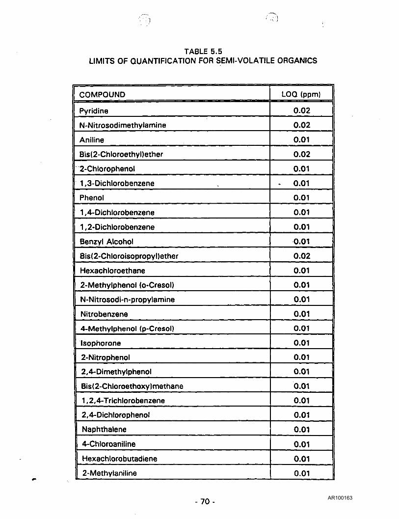
TABLE 5.5LIMITS OF QUANTIFICATION FOR SEMI-VOLATILE ORGANICS
COMPOUND
Pyridine
N-Nitrosodimethylamine
Aniline
Bis(2-Chloroethyl)ether
2-Chlorophenol
1 ,3-Dichlorobenzene
Phenol
1 ,4-Dichlorobenzene
1 ,2-Dichlorobenzene
Benzyl Alcohol
Bis(2-Chloroisopropyl)ether
Hexachloroethane
2-Methylphenol (o-Cresol)
N-Nitrosodi-n-propylamine
Nitrobenzene
4-Methylphenol (p-Cresol)
Isophorone
2-Nitrophenol
2,4-Dimethylphenol
Bis ( 2-Chloroethoxy) methane
1 ,2,4-Trichlorobenzene
2,4-Dichlorophenol
Naphthalene
4-Chloroaniline
Hexachlorobutadiene
2-Methylaniline
LOQ (ppm)
0.02
0.02
0.01
0.02
0.01
- 0.01
0.01
0.01
0.01
0.01
0.02
0.01
0.01
0.01
0.01
0.01
0.01
0.01
0.01
0.01
0.01
0.01
0.01
0.01
0.01
0.01
- 7 0 -AR100163

TABLE 5.5LIMITS OF QUANTIFICATION FOR SEMI-VOLATILE ORGANICS
(Continued)
COMPOUND
4-Chloro-3-methyl phenol
Hexachlorocyclopentadiene
2,4,6-Trichlorophenol
2,4, 5-Trichlorophenol
2-Chloronaphthalene
2-Nitronaniline
Acenaphthylene
Dimethyl phthalate
2,6-Dinitrotoluene
3-Nitroaniline
Acenaphthene
2,4-Dinitrophenol
Dibenzofuran
4-Nitrophenol
2,4-Dinitrotoluene
Fluorene
4-Chlorophenylphenyl ether
Diethyl phthalate
4-Nitroaniline
4,6-Dinitro-2-methylphenol
N-Nitrosodiphenylamine
Azobenzene
4-Bromophenylphenyl ether
Hexachlorobenzene
LOO (ppm)
0.01
0.02
0.01
0.01
- 0.010.02
0.01
0.01
0.01
0.02
0.01
0.02
0.01
0.02
0.01
0.01
0.01
0.01
0.03
0.01
0.01
0.01
0.01
0.01
-71 -AR100164

TABLE 5.5LIMITS OF QUANTIFICATION FOR SEMI-VOLATILE ORGANICS
(Continued)
COMPOUND
Pentachlorophenol
Phenanthrene
Anthracene
Carbazole
Di-n-Butyl phthalate
Fluoranthene
Pyrene
Butylbenzyl phthalate
Benzo(a)anthracene
3,3-Dichlorobenzidine
Chrysene
Bis(2-ethylhexyl)phthalate
Di-n-octyl phthalate
Benzo(b)fluoranthene
Benzo(k)fluoranthene
Benzo(a)pyrene
Indenod ,2,3-cd)pyrene
Dibenzo(a,h)anthracene
Benzo(g,h,i)perylene
LOQ (ppm)
0.01
0.01
0.01
0.01
' 0.01
0.01
0.01
0.01
0.01
0.01
0.01
0.01
0.01
0.01
0.01
0.02
0.02
0.02
0.02
LOQ Limit of Quantificationppm Parts per Million
- 7 2 -AR100165
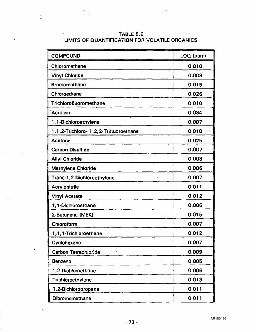
TABLE 5.6LIMITS OF QUANTIFICATION FOR VOLATILE ORGANICS
COMPOUND
Chloromethane
Vinyl Chloride
Bromomethane
Chloroethane
Trichlorofluoromethane
Acrolein
1 , 1 -Dichloroethy lene
1 ,1 ,2-Trichloro- 1 ,2,2-Trifluoroethane
Acetone
Carbon Disulfide
Allyl Chloride
Methylene Chloride
Trans-1 ,2-Dichloroethylene
Acrylonitrile
Vinyl Acetate
1,1-Dichloroethane
2-Butanone (MEK)
Chloroform
1,1,1-Trichloroethane
Cyclohexane
Carbon Tetrachloride
Benzene
1 ,2-Dichloroethane
Trichloroethylene
1 ,2-Dichloropropane
Dibromomethane
LOQ (ppm)
0.010
0.009
0.015
0.026
0.010
0.034
0.007
0.010
0.025
0.007
0.008
0.006
0.007
0.011
0.012
0.006
0.015
0.007
0.012
0.007
0.009
0.005
0.006
0.013
0.011
0.011
- 7 3 -AR100166

TABLE 5.6LIMITS OF QUANTIFICATION FOR VOLATILE ORGANICS
(Continued)
COMPOUND
Bromodichloromethane
2-Chloroethyl Vinyl Ether
Trans- 1 ,3-Dichloropropene
4-Methyl-2-Pentanone; MIBK
Toluene
Cis-1 ,3-Dichloropropene
1 , 1 ,2-Trichloroethane
Tetrachloroethylene
2-Hexanone
Dibromochloromethane
1 ,2-Dibromomethane
Chlorobenzene
1 ,1 ,1 ,2-Tetrachloroethane
Ethylbenzene
m,p-Xylene
o-Xylene
Styrene
Bromoform
1 , 1 ,2,2-Tetrachloroethane
1,2,3-Trichloropropane
1 ,3-Diochlorobenzene
1 ,4-Dichlorobenzene
1 ,2-Dichlorobenzene
LOO (ppm)
0.005
0.009
0.005
0.011
0.010
0.006
0.0096
0.028
0.011
0.006
0.006
0.011
0.005
0.005
0.006
0.006
0.006
0.007
0.013
0.007
0.018
0.019
0.014
LOQ Limit of Quantificationppm Parts per Million
- 74-AR100167
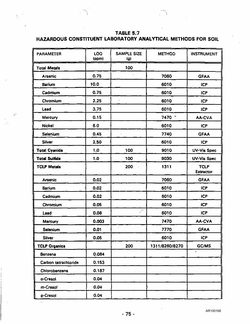
TABLE 5.7HAZARDOUS CONSTITUENT LABORATORY ANALYTICAL METHODS FOR SOIL
PARAMETER
Total Metals
Arsenic
Barium
Cadmium
Chromium
Lead
Mercury
Nickel
Selenium
Silver
Total Cyanide
Total Sulftde
TCLP Metals
Arsenic
Barium
Cadmium
Chromium
Lead
Mercury
Selenium
Silver
TCLP Organics
Benzene
Carbon tetrachloride
Chlorobenzene
o-Cresol
m-Cresol
p-Cresol
LOQ(ppm)
0.75
10.0
0.75
2.25
3.75
0.15
6.0
0.45
2.50
1.0
1.0
0.02
0.02
0.02
0.05
0.08
0.003
0.01
0.05
0.084
0.153
0.187
0.04
0.04
0.04
SAMPLE SIZE(a)
100
100
100
200
•ff
200
METHOD
7060
6010
6010
6010
6010
7470 *
6010
7740
6010
9010
9030
1311
7060
6010
6010
6010
6010
7470
7770
6010
1311/8260/8270
INSTRUMENT
GFAA
ICP
ICP
ICP
ICP
AA-CVA
ICP
GFAA
ICP
UV-Vis Spec
UV-Vis Spec
TCLPExtractor
GFAA
ICP
ICP
ICP
ICP
AA-CVA
GFAA
ICP
GC/MS•
- 7 5 -AR100168

TABLE 5.7HAZARDOUS CONSTITUENT LABORATORY ANALYTICAL METHODS FOR SOIL
(Continued)
PARAMETER
Cresol
1 ,4-Oichlorobenzene
1 ,2-Dichloroethane
1 , 1 -Dichloroethylene
2,4-Dinitrotoluene
Hexachlorobenzene
Hexachloroethane
Methyl ethyl ketone
Nitrobenzene
Pentrachlorophenol
Pyridine
Tetrachloroethylene
Trichloroethylene
2,4,5-Trichlorophenol
2,4,6-Trichlorophenol
Vinyl chloride
Semi-Volatile Organicsw/Library Search
Volatile Organicsw/Library Search
Total PetroleumHydrocarbon
LOQ(ppm)
0.12
0.323
0.238
0.119
0.04
0.04
0.04
0.255
0.04
0.04
0.08
0.476
0.221
0.04
0.04
0.153
SeeTable 5.5
SeeTable 5.6
100mg/kg
SAMPLE SIZE(g)
4 0 g x 2
2 0 g x 2
60gms
METHOD
-
-
8270
8260
9070/413
INSTRUMENT
GC/MS
GC/MS
Gravimetric
- 7 6 - AR100169

6.0 SITE SPECIFIC CHARACTERIZATION PLANS
6.1 SURFACE GEOPHYSICAL SURVEYS
Surface geophysical surveys will be conducted within the study area to
locate and define the boundaries of buried waste, map conductive
contaminant plumes and locate underground utilities. The specific
objectives of conducting surface geophysical surveys within the study area
are as follows:
• Delineate the boundaries of the Abandoned Canal, East and West
Plant Dumps, Underground Silos, and the disposal area under Pipe
Shop;
• Identify physical forms and quantities of buried waste;
• Locate drain lines and select adjacent soil sampling locations;
• Locate underground utilities so that they may be avoided during soil
sampling; and,
• Identify contaminant plumes for correlation with groundwater
sampling locations.
Surface geophysical surveys will be the first characterization technique
performed within the study area. Prior to conducting the surface
geophysical surveys the area will be cleared of undergrowth and a 20' x
20' grid pattern established. An EM survey as described in Section 3.1
will be conducted first by taking readings with an EM-31 or equivalent
instrument over the grid lines shown on Figure 2. The magnetometer
survey will be conducted following the EM survey to identify buried ferrous
objects. The raw data from these two surveys will be reviewed in the field
and areas where anomalies are indicated will be selected for surveying
- 7 7 -AR100170

using GPR. As described in Section 3.1.2, GPR will provide a
cross-sectional picture which will be used to estimate the configuration
and depths of buried disposal areas and buried waste. Based on available
information concerning previous disposal activities, is anticipated that GPR
will be conducted over the suspected area of the Abandoned Canal, East
and West Plant Dumps, Underground Silos, and Pipe Shop (see Figure 2).
If required the geophysical data will be computer processed to provide for
spatial corrections, overlay the electromagnetic and GPR data, and/or
contour the data.
6.2 RADIOLOGICAL SURVEYS
Radiological surveys with portable radiation detectors will be performed to
determine the location of areas with radiation levels in excess of
background levels, the extent of contamination in activity levels, and
affected area or volume. The procedures and equipment described in
Section 3.2 will be used for the radiological surveys.
6.2.1 GROUND SURVEYS
A continuous gamma scan will be performed over the study area
grounds along a 10' x 10' (see Figure 3) grid in areas with a
moderate to high potential of contamination and a 20'x20' grid
in areas with a low potential of contamination using 2" x 2" Nal
detector. The locations of direct radiation exceeding 2 times the
background level will be marked on site sketches or maps and
identified for consideration for surficial soil sampling.
Numerous areas located south of the SLC Main Building are
documented disposal areas for radioactive waste or have been
contaminated through the storage and use of radioactive
materials within the study area. Radiological contamination has
- 7 8 - AR100171

also been documented in the northern part of the SLC study area
although to a much lesser degree.
(The majorityjprthe buildings within the sjtudy^ireajiaye been
icjDntarnjr@ted_or are susj)ected of being contaminated through
jthe~storage~~and yse^ ofj-adipactive. materials. Most qf_the/
buildings^r^abandonecl[ora^used solely for storage. However,
the Nuclear Building, Machine Shop, and portions of the Main and
Etching Buildings are currently used for production operations.
Radiological surveys will be performed on the interior of these
buildings in accordance with the procedures in Section 3.2.
jPrior to entering the buildings to perform radiological suryeys_an
inspection wiljjae performed ojjthe structurafintegrityJ/Tnt is~)" ~~ • —— __. ^- .—I
(determinelttrlat~the~bu iId inrglsTunsaf eTtb^ent¥r measureiTwiII be
radiologicaT surVey^~withbuf^elTteTirTg~the
of ~mountihg~radiation detection "devices~oni
(extension rods or suspending the detectors with cords or ropes;
(The^tructuraLintegrity- of the Old House .and .Personnel _0f f ice
r"Buildingjppears to bejjnsgundj^
As many of the buildings are utilized for the storage of
contaminated and uncontaminated items a general inventory of
the contents will be made of the items in place. The inventory
will note the types of items stored, configuration, access
constraints, and locations of "hot spots" on the items. In no
event will the stored items be moved without the prior approval
of the RCS and SLC Radiation Control Officer (RCO).
- 79 -AR100172
Composite samples of the construction materials will be taken as
determined in the field within rooms or areas which have similar
contamination. These samples will be analyzed for gross alpha,
gross beta, liquid scintillation, and gamma spectroscopy. If the
analytical results indicate elevated gross beta the samples will be
analyzed by radiochemistry for ^Sr. Samples taken from portions
of the Main Building may also be analyzed by radiochemistry for63Ni.
6.2.3 BOREHOLE SURVEYS
Twenty-three boreholes will be drilled within the study area (see
Figure 5) to allow for the identification of radiological and/or
hazardous contaminants through the laboratory analyses of
subsurface soil samples or direct field measurement. All
boreholes will be gamma logged using the procedures in Section
3.2 and the gamma measurements recorded with depth.
Samples will be collected from all 23 boreholes. Samples from
9 of the boreholes will be submitted for laboratory analyses.
Samples from the remaining 14 boreholes will be retained and
analyzed if additional information is required.
The gamma measurements will be compared to laboratory
analyses to determine whether a correlation exists between the
two sets of data.
6.2.4 TEST TRENCH SURVEYS
Nine test trenches will be excavated within the study area (see
Figure 6) to allow for the identification of radiological and
hazardous contaminants through the laboratory analyses of
subsurface soil samples or direct field measurements. All test
trenches will be scanned for gamma radiation using the
- 8 0 -AR100173

procedures in Section 3.2. Elevated measurements will be noted
on site sketches or maps. The results of the gamma survey will
be used to select soil sampling locations within the test trenches.
6.3 SOIL SAMPLING
Both surface and subsurface soil samples will be collected within the study
area.
Surface soil samples (SS) will be collected at the following locations:
• Predetermined locations within 100'x100' grid blocks along the
southern portion of the study area;
• Site specific locations at areas of known contamination;
• Locations of observed contamination based on radiological and
geophysical surveys (the locations will be selected in the field during
the characterization activities); and
• Within test trench excavations.
The methodology for collecting the surface soil samples is described in
Section 3.3. The locations of the surface soil samples are shown on
Figures 3, 4, and 6. The radiological and hazardous constituents for
laboratory analyses are shown on Tables 6.1, 6.2, and 6.3.
The laboratory analytical results from the surface soil samples will identify
specific contaminants, concentrations, and the lateral extent of
contamination.
Three types of subsurface soil samples will be collected: deep subsurface
samples (DS), borehole soil samples (BH), and concrete core samples. All
subsurface soil samples will be collected at site specific location of known
contamination.
-81 -AR100174

Deep subsurface soil samples will be collected from 0.5' to 4.5' and
composited into one sample for laboratory analyses. The 0-0.5' increment
from the deep subsurface soil sampling location will be collected as a
discrete surface soil sample or composited with other similar surface soil
samples. Borehole subsurface soil samples will be collected in 4'
increments from the land surface to a specific target depth (i.e., bottom of
Abandoned Canal). Of the 23 boreholes to be drilled samples will be
collected and analyzed by a laboratory from 9 boreholes. Samples will be
collected and retained from the remaining 14 boreholes. If no correlation
can be made between analytical results and gamma logging of the
boreholes the retained samples may also be analyzed.
The methodology for collecting the subsurface soil samples is described in
Section 3.4. The locations of the subsurface soil samples are shown on
Figures 4 and 5. The radiological and hazardous constituents for
laboratory analyses are shown on Tables 6.4, 6.5, and 6.6.
The laboratory analytical results from the subsurface soil samples will
identify specific contaminants, concentrations, and the vertical extent of
contamination.
A summary of the soil samples and analytical parameters is shown on
Table 6.7. Site specific soil sampling strategies are described below.
6.3.1 GRID SURFACE SOIL SAMPLING (100' X 100' GRID)
Surface soil sampling (0-6") will be conducted at 21 locations
within the southern portion of the study area (see Figure 3)
within 100' x 100' grid blocks. Within each grid block a soil
sample will be collected at the center and at four points midway
between the center and the block corners and then composited
- 8 2 -AR100175

into one sample for laboratory analyses. The results from this
sampling will provide an unbiased indication of surficial
contamination showing specific contaminants and corresponding
concentrations of contaminants. All samples will be analyzed for
radiological parameters.
6.3.2 ABANDONED CANAL
At one time in the past, the Abandoned Canal (No. 37, Figure 1)
was open throughout the entire length of the study area.
Available documentation indicates the canal portion has a high
potential for gross contamination. The Abandoned Canal extends
from the east property boundary to the west property boundary.
Although the East Lagoon, East Plant Dump, West Lagoon, and
West Plant Dump appear to be part of the canal system, these
sites will be characterized separately.
Upon definition of the boundaries of the Abandoned Canal by
geophysical and/or radiological surveys, a total of 10 boreholes
will be advanced through the canal to an anticipated depth of 12'
below land surface (see Figure 5). Samples will be collected at
4' intervals from each borehole. Samples collected from 3
boreholes (37-BH-1, 37-BH-4, and 37-BH-7) will be sent to a
contract laboratory for analyses. Samples collected from the
remaining seven boreholes will be retained and analyzed if
additional data is required.
Five test trenches will be excavated across the width of the
Abandoned Canal (see Figure 6). One composite soil sample will
be collected for laboratory analyses from each test trench.
- 8 3 -AR100176

The Abandoned Canal has a high potential for multiple
contaminants; therefore, a wide variety of radiological and
hazardous constituent parameters have been selected for
analyses.
6.3.3 EAST LAGOON
Up to the period of 1960, liquid waste was routed to the East
Lagoon (No. 18, Figure 1). A total of 4 surface soil samples will
be collected along the banks of the East Lagoon just above the
water line and composited into one sample for laboratory
analyses (see Figure 4). Analytical results from this sample will
provide an estimate of surficial contamination within the East
Lagoon.
A borehole will be advanced along the southern edge of the
lagoon and samples collected and analyzed at 4' intervals to
provide information concerning the depth of contamination and
identify migration of contaminants from the lagoon (see Figure 5).
Information concerning the types of liquid waste disposed of in
this lagoon from the Main Building provided guidance in the
selection of the analytical parameters.
6.3.4 WEST LAGOON
Up to the period of 1960, liquid waste was routed to the West
Lagoon (No. 30, Figure 1). A total of 7 surface soil samples will
be collected along the banks of the West Lagoon just above the
water line and composited into two samples for laboratory
analyses (see Figure 4). Analytical results from these samples
will provide an estimate of surficial contamination within the
West Lagoon.
- 84 -AR100177

Two boreholes will be advanced along the southern edge of the
lagoon and samples collected at 4' intervals to provide
information concerning the depth of contamination and the
migration of contaminants from the lagoon (see Figure 5).
Samples collected from borehole 30-BH-1 will be sent to a
contract laboratory for analyses. Samples collected from
borehole 30-BH-2 will be retained and analyzed if additional
information is required.
Information concerning the types of liquid waste disposed of in
the lagoon from the Etching Building provided guidance in the
selection of analytical parameters.
6.3.5 EAST AND WEST PLANT DUMPS
Prior to 1970, the Plant Dumps were used to dispose of
radioactive waste. These sites appear to be part of the
Abandoned Canal. Geophysical and radiological surface surveys
will be necessary to assist in delineating the boundaries of the
Plant Dumps prior to soil sampling. To characterize the lateral
extent of contamination at both Plant Dumps, 3 surface soil
samples and a 0-6" sample from a deep subsurface soil sample
location will be collected and composited into one sample for
laboratory analyses.
To determine the vertical extent of contamination, a 0.5'-4.5'
deep subsurface soil sample will be collected at both Plant
Dumps (see Figure 4).
As described in Section 6.4 one composite soil sample will be
collected from each test trench excavated through the Plant
Dumps (see Figure 6).
- 8 5 -AR100178

Similar to other portions of the Abandoned Canal, the potential
contaminants are numerous; therefore, a wide variety of
' radiological and hazardous constituents have been selected for
/ analyses.
6.3.6 LOCALIZED CONTAMINATED SOIL AREAS
The localized Contaminated Soil Areas include the following sites:
• Contaminated Soil Area in front of Above Ground Metal Silo
(No. 3, Figure 1).
• Contaminated Soil Area north of Machine Shop (No. 12,
Figure 1).
• Contaminated Soil Area under Loading Dock (No. 22, Figure
1).
• Contaminated Soil Area south of Radium Vault (No. 38,
Figure 1).
• Contaminated Soil Area east of 8'x8' Building (No. 41,
Figure 1).
These contaminated soil areas appear to be the result of
personnel traffic to and from adjacent buildings due to observed
contamination near the exit doorways.
The lateral extent of contamination appears to be limited and will
be verified by the radiological surface survey. At each site, three
surface soil samples will be collected and composited into one
sample for laboratory analyses.
At each site one location has been selected for a 0.5' to 4.5'
deep subsurface soil sampling to determine the vertical extent of
contamination (see Figure 4). The first increment (0-0.5') of the
- 8 6 -AR100179

deep subsurface sample will make up the third surface soil
sample for the composite.
Past use of materials within these buildings were used to select
parameters for analyses.
6.3.7 UNDERGROUND SILOS
The Underground Silos (No. 17, Figure 1) were used during the
period of 1950-1960 for the disposal of solid radioactive waste
(see Section 2.5.14 for details). The approximate dimensions
and locations have been determined from existing information,
however, to obtain additional data and to verify historical data,
surface geophysical surveys will be conducted over and around
the Underground Silos.
CNSI has determined that direct sampling of the contents of the
Underground Silos poses unacceptable risks of contaminant
exposure to workers at the present time. As an alternative to
direct sampling, investigations will be conducted to verify and
determine the dimensions and type of construction of the
Underground Silos by sampling media (ie, soil and groundwater)
immediately outside or downgradient of the silos to infer the
specific constituents and activity within the confines of the silos.
Three surface soil samples will be collected within the fenced
area of the silos and composited into one sample for laboratory•
analyses (see Figure 4). The analytical results from this sampling
will characterize surficial contamination.
To characterize contamination with depth, 2 boreholes will be
advanced adjacent to each silo (see Figure 5). Soil sampling will
- 8 7 -AR100180

be conducted at 4' intervals from each borehole. The anticipated
target depth is 15' and/or at least 2' below the water table.
Samples collected from borehole 17-BH-1 will be sent to a
contract laboratory for analyses. Samples collected from
borehole 17-BH-2 will be retained and analyzed if additional
information is required.
Information regarding the suspected contents of the silos was
used to select parameters for analyses.
6.3.8 CONTAMINATED SOIL AREAS ADJACENT TO OLD BERWICKROAD AND VANCE/WALTON PROPERTY
These two sites are represented by contaminated soil piles. The
Contaminated Soil Area adjacent to Old Berwick Road (No. 34,
Figure 1) is located north of the Annex Building (northwest corner
of study area). The origin of this 226Ra contaminated soil pile is
unknown; however, the soil may have resulted from grading
activities when the Annex Building was constructed. The
Contaminated Soil Area from the Vance/Walton Property is
located southeast of the Above Ground Metal Silo and is the
result of the removal of 137Cs contaminated soil from the
Vance/Walton property.
Upon completion of a surface radiological survey, the lateral
extent of contamination will be determined by 2 surface soil
samples taken at the visible edges of the piles and composited
into one sample for laboratory analyses (see Figure 4).
The vertical extent of contamination and concentration of
contaminants within the piles will be determined by 3 deep
subsurface soil coring locations (in this case subsurface refers to
below the surface of the pile). These three deep subsurface
- 8 8 - AR100181

samples will be composited into one sample for laboratory
analyses. The maximum depth of subsurface sampling should
not exceed 5'.
Knowledge of the contaminants within the two soil piles was
used to select parameters for analyses.
6.3.9 PERSONNEL OFFICE BUILDING
The Personnel Office Building (No. 27, Figure 1) is of particular
interest due to a suspected "dry well" in the basement which
may have been used for the disposal of radioactive waste (226Ra
and Sr).
Direct sampling of this well would be extremely hazardous due to
the instability of the building structure and inherent dangers
involved in confined space entry. If disposal activities did take
place in the well in the Personnel Office Building, given the
permeable nature of the underlying sediments and high mobility
of ^Sr, investigation of the downgradient groundwater should
provide information regarding the presence of contamination
within the well.
To assess whether contamination is migrating via groundwater,
a borehole will be advanced south of the Personnel Office
Building and samples collected and retained at 4' intervals (see
Figure 5). The anticipated depth for the borehole is 25' below
land surface. The samples will be analyzed if additional
information is required.
- 8 9 -AR100182

6.3.10 PIPE SHOP
During 1948, 226Ra contaminated ductwork was disposed in a
portion of the open canal system. This area was backfilled and
the Pipe Shop (No. 29, Figure 1) was constructed over the
disposal location. Elevated radon levels within the Pipe Shop
support evidence of past disposal activities.
Detailed surface geophysical surveys will be carried out within
this portion of the study area to define the boundaries of solid
waste disposal. To characterize the contamination with depth,
one borehole (29-BH-1) will be advanced to the base of the
Abandoned Canal disposal area (see Figure 5). Soil samples will
be collected and retained at 4' intervals from the borehole. The
samples will be analyzed if additional information is required.
In the event the Pipe Shop completely overlies the disposal area
a concrete coring machine will be used to provide access for soil
sampling below the concrete (see Figure 5 and Section 3.9).
6.3.11 CONTAMINATED SOIL AREA NORTH OF LACQUER STORAGE
BUILDING
At some period in the past, direct disposal of solvents have been
reported to occur between the Main Building and the Lacquer
Storage Building.
During the early to mid-70's, an accidental release of heating fuel
(diesel) occurred near monitoring well No. 11 and also has been
detected, to a lesser degree, in adjacent monitoring wells.
To assess the potential extent of soil contamination due to the
disposal of solvent waste, 2 surface soil samples will be collected
- 9 0 - AR100183

from the 0-0.5' increment at the deep subsurface soil sampling
locations and composited into one sample for laboratory analyses
(see Figure 4).
The vertical extent of contamination will be determined by
comparing composite samples collected from 2 deep subsurface
soil sampling locations.
The vertical extent of diesel fuel contamination will be determined
by drilling a borehole adjacent to the suspected spill area (see
Figure 5). Soil samples will be collected and analyzed at 4'
intervals from the borehole. The soil samples collected at the
borehole location will be analyzed for hazardous constituents and
total petroleum hydrocarbons.
6.3.12 LIQUID WASTE BUILDING
As discussed in Section 2.5.17, the Liquid Waste Building (No. 7,
Figure 1) overlies the location of a below-grade vault. Prior to
1972, the below-grade vault was used to house a hold-up tank
and evaporator system and later used for liquid waste dilution.
During 1972, a flood damaged this facility and the below-grade
vault was filled in and the present Liquid Waste Building
constructed over this location. Damage from the flood resulted
in a release of contaminated liquid. Elevated radon levels within
the present structure support the presence of subsurface
contamination.
Two borehole locations have been selected adjacent to the Liquid
Waste Building (see Figure 5). Soil samples will be collected from
the boreholes at 4' intervals. Samples collected from borehole
7-BH-1 will be sent to a contract laboratory for analyses.
-91 -AR100184

Samples collected from borehole 7-BH-2 will be retained and
analyzed if additional data is required.
One concrete core will be conducted within the building to allow
for the collection of a subsurface soil sample (see Figure 5).
Radiological and hazardous constituent analyses conducted on
these soil samples will identify specific contaminants with depth
and the migration of contaminants from beneath the building.
6.3.13 OLD HOUSE
The Old House (No. 6, Figure 1) has been in the past and is
currently used to store radioactively contaminated equipment and
materials. To determine if any contamination has accumulated in
the dug-out earthen basement, 2 surface soil samples will be
collected and composited into one sample for analyses (see
Figure 4).
6.3.14 DRAIN LINES (DRAINAGE DITCH FROM EAST PLANT DUMP TO
SUSQUEHANNA RIVER)
The drainage ditch, beginning in the vicinity of the East Plant
Dump and terminating at the Susquehanna River (No. 33,
Figure 1) has been determined to be a source of radioactive
contamination (CNSI, 1990). Although the ditch accepts water
from the Multimetals NPDES discharge line (nonradioactive
effluent), the surface water and/or sediment along the drainage
ditch have been contaminated with radioactive constituents,
presumably due to surface contamination at the East Plant Dump.
One borehole will be advanced next to Monitoring Well No. 5,
and samples collected at 4' intervals and retained (see Figure 5).
- 9 2 - AR100185

Samples collected from the borehole will be analyzed if additional
data is required.
6.3.15 CONTAMINATED SOIL AREAS BETWEEN ABANDONED CANAL
AND RIVER
The Contaminated Soil Areas between the Abandoned Canal and
River (Nos. 13-16, Figure 1) may have resulted from the 1972
flood, which spread contamination from several known areas of
contamination (ie. Plant Dumps and Lagoons). The results of the
characterization activities conducted by CNSI during 1990 show
that the contamination appears to be isolated to surficial deposits
when road improvements were conducted along this area.
Grading of soils in this area removed the majority of observed
contamination. Upon completion of the radiological ground
survey along grid lines, specific areas of elevated contamination
will be identified.
Surficial soil samples and deep subsurface soil samples will be
collected at areas with elevated direct measurements. For the
purposes of this plan it is assumed that 12 surface soil samples
will be composited into 4 samples for analyses. Four deep
subsurface soil samples will be also collected for analyses.
However, the actual number and sampling locations will be
determined in the field. All samples will be analyzed for
radiological parameters.
6.3.16 SIDEWALK AREAS
The Main Building has been used in the past for the
manufacturing of radioactive products. Access from the Main
Building, during this time, resulted in the spread of contamination
to the sidewalk areas. Elevated areas have been identified near
- 9 3 -AR100186

the doorways. Four locations have been selected to core the
concrete and sample the underlying soils (see Figure 5). Samples
will be analyzed for radiological parameters.
6.4 TEST TRENCH EXCAVATIONS AND SAMPLING
Nine test trenches will be excavated and sampled within the study area to
investigate the subsurface conditions. Test trenches will be excavated in
accordance with the procedures in Section 3.6. Following excavation,
radiological surveying and soil sampling will be performed in accordance
with the procedures in Sections 3.2 and 3.3. Test trenches will be
excavated through the suspected location of the Abandoned Canal, around
portions of the perimeter of the Underground Silos, and through the East
and West Plant Dumps. The locations of the test trenches are shown on
Figure 6 and the parameters for analyses of the soil samples are shown on
Table 6.3.
6.4.1 ABANDONED CANAL
The Abandoned Canal extended along the southern boundary of
the SLC property parallel to the river. The exact location is
unknown, however, the location has been assumed based on
topographic features. As described in Section 2.5.34, at least
portions of the Abandoned Canal were used for the disposal of
radioactive waste.
Five test trenches will be excavated in sequence from east to
west across the suspected boundaries of the Abandoned Canal.
These test trenches will be used to determine the exact location
and depth of the canal and visually observe any buried waste or
contaminated soil. Upon completion of each test trench, the
trench will be radiologically surveyed using direct measurements.
Based on visual observations and radiological survey readings,
- 9 4 - AR100187

five locations will be sampled from the bottom and/or walls of
each test trench and composited into one sample for laboratory
analyses.
As the Abandoned Canal has a high potential for multiple
contaminants a wide variety of radiological and hazardous
constituent parameters have been selected for analyses.
6.4.2 EAST AND WEST PLANT DUMPS
The East Plant Dump is located between the East and West
Lagoons. The West Plant Dump is located west of the West
Lagoon. As described in Sections 2.5.25 and 2.2.28, both
dumps were used for the disposal of radioactive waste.
A test trench will be excavated through each dump to define the
horizontal and vertical extent of the dumps and type of waste or
contamination present. Upon completion of each test trench, the
trench will be radiologically surveyed using direct measurements.
Based on visual observations and radiological survey readings five
locations will be sampled from the bottom and/or walls of each
test trench and composited into one sample for laboratory
analyses.
The parameters for analyses were selected based on information
concerning past waste disposal practices.
6.4.3 UNDERGROUND SILOS
The Underground Silos are two 3/16" circular steel cylinders used
for the disposal of solid radioactive waste. Due to the unknown
radiological activity of the waste within the silos, a semi-circular
test trench will be excavated around the perimeter of each silo.
-95 -AR100188

The test trenches will allow determination of the exact
construction of the silos, the current condition of the silos and a
radiological survey of the exterior of the silos, without exposing
the waste or breaching the silos. If physically possible, the test
trenches will be excavated to the depth of the silos
(approximately 15').
Based on visual observations and direct radiological survey
readings, soil samples from two locations will be collected from
each trench and composited into one sample for analyses.
Parameters for analyses were selected based on infomation
concerning waste disposed of in the silos.
6.5 GROUNDWATER SAMPLING
Groundwater sampling will be conducted within the study area to obtain
representative groundwater samples for radiological and hazardous
constituent analyses. The detection of specific contaminants will assist in
the identification of radiological and hazardous contamination source areas.
In addition, the occurrence and concentration of contaminants will assist
in the determination of mobility and toxicity of the contaminants in the
groundwater flow system.
Twenty-two groundwater samples will be collected at existing monitoring
wells within the study area (see Figure 5). The methodology for
groundwater sampling is described in Section 3.7. Table 6.1 lists the
monitoring wells for groundwater sampling and shows the associated site
under investigation.
All twenty-two groundwater samples will be analyzed for radiological
parameters (see Table 5.2). In addition, 13 of the 22 groundwater
- 9 6 -AR100189

samples will be analyzed for hazardous constituent parameters (see Table
5.4). These wells are highlighted on Table 6.8. The rationale for the
selection of these wells for hazardous constituent analyses is described
below.
Monitoring well GW-15 will provide a sample upgradient of the study area.
Monitoring wells GW-A and GW-G will act as control points for the study
area boundaries. Monitoring wells GW-19 and GW-22 were selected for
sampling as they had elevated radiological results during the CNSI 1990
sampling effort. Monitoring wells GW-11, GW-12, and'GW-13 were
selected to determine the lateral extent of contamination from the diesel
fuel spill which occurred adjacent to GW-11. Monitoring wells GW-1 and
GW-5 will be used to identify the migration of any hazardous constituents
from the Underground Silos and Drainage Ditch Area, respectively.
Monitoring wells GW-A, GW-D, GW-4, and GW-7 were selected to identify
the migration of any hazardous constituents from the Abandoned Canal.
6.6 SURFACE WATER SAMPLING
Surface water sampling will be conducted within the study area to obtain
representative surface water samples for radiological and hazardous
constituent analyses in accordance with the methodologies presented in
Section 3.8. The analyses will determine whether the surface water in a
source of contamination and the method of management upon removal.
Surface water samples will be collected from the East and West Lagoons.
The locations for surface water sampling are shown on Figure 6. The
surface water samples will be analyzed for radiological and hazardous
constituents (see Tables 5.2 and 5.4).
- 9 7 -AR100190

6.6.1 EAST LAGOON
The East Lagoon is an unlined earthen surface impoundment used
previously for the disposal of radioactive and non-radioactive
waste water. Two surface water samples will be collected from
the East Lagoon and composited into one sample for radiological
and hazardous constituent analyses.
6.6.2 WEST LAGOON
The West Lagoon is an unlined earthen surface impoundment
used previously for the disposal of radioactive and
non-radioactive waste water. Three surface water samples will
be collected from the West Lagoon and composited into one
sample for radiological and hazardous constituent analyses.
- 9 8 -AR100191

TABLE 6.1LABORATORY PARAMETER MATRIX FOR SURFACE SOIL SAMPLES WITHIN GRID BLOCKS
(I SOIL SAMPLE DESIGNATION
II SS
II 01
RADIOLOGICAL ANALYSES:
Gross Alpha
Gross Beta
Liquid Scintillation
Gamma Spactroscopy
Radiochemistry (Ni-63)
Radiochamistry (Sr-90)
HAZARDOUS CONSTITUENTANALYSES:
Total Metals
Total Cyanida
Total Sulfide
TCLP Metals
TCLP Organlcs
Volatile Organics
Sami-Volatila Organics
Total Petroleum Hydrocarbons
1
1
1
•
SS-02
1
1
1
1
•
ss-03
1
1
1
1
•
ss-04
1
1
1
1
•
ss-05
1
1
1
1
•
88-06
1
1
1
1
•
ss-07
1
1
1
1
•
ss-08
1
1
1
1
•
ss-09
1
1
1
1
•
ss-10
1
1
1
1
•
ss-11
1
1
1
1
•
ss-12
1
1
1
1
•
ss-13
1
1
1
1
•
ss-14
SS-15
1
1
1
1
•
1
1
1
1
t
- 99 -AR100192

TABLE 6.1LABORATORY PARAMETER MATRIX FOR SURFACE SOIL SAMPLES WITHIN GRID BLOCKS
(Continued)
RADIOLOGICAL ANALYSES:
Gross Alpha
Gross Bota
Liquid Scintillation
Gamma Spectroscopy
Radiochemistry (Ni-63)
Radiochemistry (Sr-90)
HAZARDOUS CONSTITUENTANALYSES:
Total Matals
Total Cyanide
Total Sulfida
TCLP Metals
TCLP Organlcs
Volatile Organics
Semi-Volatile Organics
Total Petroleum Hydrocarbons
SOIL SAMPLE DESIGNATION
SS-16
1
1
1
1
•
ss-17
1
1
1
1
•
ss-18
1
1
1
1
•
ss-19
1
1
1
1
•
ss-20
1
1
1
1
•
ss-21
1
1
1
1
•
i
NOTES: Grid block locations shown on Figure 3.Numbers in table indicate number of samples per analytical parameter.' Sr-90 will be analyzed if gross alpha/beta is elevated.
- 100-AR100193

TABLE 6.2LABORATORY PARAMETER MATRIX FOR SURFACE SOIL SAMPLES
DESIGNATION OF COMPOSITE SAMPLE
RADIOLOGICAL ANALYSES:
Grose Alpha
Gross Beta
Liquid Scintillation
Gamma Spactroscopy
Radiochamistry (NI-63)
Radiochamiatry (Sr-90)
HAZARDOUS CONSTITUENTANALYSES:
Total Matala
Total Cyanida
Total Sulfida
TCLP Matals
TCLP Organics
Volatile Organica
Sami-Volatila Organica
Total Petroleum Hydrocarbons
DESIGNATION OF SOIL SAMPLE LOCATIONS
03-SS-01
03-SS-02
O3-DS-01
03-SS-1/2
08-SS-01
06-SS-02
06-SS-1/2
12-SS-01
12-SS-02
12-DS-01
12-SS-1/2
13-SS-01
13-SS-02
13-SS-03
13-SS-1/3
1
1
1
1
•
1
1
1
1
•
1
1
1
1
•
1
1
1
1
•
i
14-ss-01
14-SS-02
14-SS-03
14-SS-1/3
1
1
1
1
•
- 101 -
AR100194

TABLE 6.2LABORATORY PARAMETER MATRIX FOR SURFACE SOIL SAMPLES
(Continued)
DESIGNATION OF COMPOSITE SAMPLE
RADIOLOGICAL ANALYSES:
Gross Alpha
Gross Beta
Liquid Scintillation
Gamma Spectroscopy
Radiochemistry (Ni-63)
Radiochemiatry (Sr-90)
HAZARDOUS CONSTITUENTANALYSES:
Total Metals
Total Cyanide
Total Sulfide
TCLP Metals
TCLP Organlos
Volatile Organics
Semi-Volatile Organics
Total Petroleum Hydrocarbons
DESIGNATION OF SOIL SAMPLE LOCATIONS
15-SS-01
15-SS-02
15-SS-03
15-SS-1/3
16-SS-01
16-SS-02
16-SS-03
18-SS-1/3
17-SS-01
17-SS02
17-SS-03
17-SS-1/3
18-SS01
18-SS-02
18-SS-03
18-SS-1/4
18-SS-04
1
1
1
1
•
1
1
1
1
•
1
1
1
1
•
t
1
1
1
1
1
•
1
1
1
1
- 102-AR100195

TABLE 6.2LABORATORY PARAMETER MATRIX FOR SURFACE SOIL SAMPLES
(Continued)
DESIGNATION OF COMPOSITESAMPLES
COMPOSITE INTERNAL RADIOLOGICALANALYSES:
Grose Alpha
Gross Beta
Liquid Scintillation
Gamma Spactroscopy
Radiochemistry (Ni-63)
Radiochamistry (Sr-901
HAZARDOUS CONSTITUENTANALYSES:
Total Metals
Total Cyanide
Total Sulfide
TCLP Metals
TCLP Organics
Volatile Organics
Semi-Voletila Organics
Total Petroleum Hydrocarbons
DESIGNATION OF SOIL SAMPLE LOCATION
22-SS-01
22-SS-
22-SS-02
22-OS-01
1/2
28-SS-01
28SS-02
28-SS-03
28-DS-01
28-SS-1/3
30-SS-01
30-SS-02
30-SS-03
30-SS-1/3
30-SS-04
30-SS-05
30-SS06
30-SS-07
30-SS-4/7
1
1
1
1
•
1
1
1
1
1
•
1
1
1
1
1
1
1
1
•
1
1
1
1
t
1
1
1
1
1
•
1
1
1
1
- 103 -AR100196

TABLE 6.2LABORATORY PARAMETER MATRIX FOR SURFACE SOIL SAMPLES
(Continued)
DESIGNATION OF COMPOSITE SAMPLE
RADIOLOGICAL ANALYSES:
Gross Alpha
I Gross Beta
Liquid Scintillation
Gamma Spaotroscopy
Radiochamlatry (Ni-63|
Radiochemistry (Sr-90)
HAZARDOUS CONSTITUENTANALYSES:
Total Matals
Total Cyanide
Total Sulflde
TCLP Matala
TCLP Organic*
Volatile Organlca
Semi-Volatile Organics
Total Petroleum Hydrocarbons
DESIGNATION OF SOIL SAMPLE LOCATION
31-SS-01
31-SS-02
31-SS-03
31-DS-01
31-SS-1/3
34-SS01
34-SS-02
34-SS-1/2
35-SS-01
35-SS02
35-SS-1/2
38-SS01
38-SS-02
38-DS-01
38-SS-1/2
41-SS01
41-SS-02
41-DS-01
41 SS-1/2
1
1
1
1
•
1
1
1
1
1
1
1
•
1
1
1
1
•
1
1
1
1
•
i
1
1
1
1
•
NOTES: Surface soil sample locations shown on Figure 4.Numbers in table indicate number of samples per analytical parameter.Surface soil sample locations for sites No. 13. 14. 15, and 16 will be selected in the field based on the results of the geophysical and radiological ground surveys.* Sr-90 will be analyzed if gross alpha/beta is elevated.
- 104-AR100197
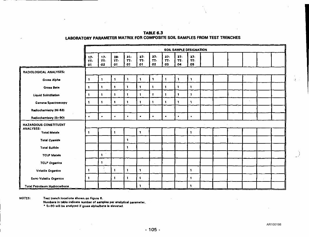
TABLE 6.3LABORATORY PARAMETER MATRIX FOR COMPOSITE SOIL SAMPLES FROM TEST TRENCHES
RADIOLOGICAL ANALYSES:
Gross Alpha
Gross Beta
Liquid Scintillation
Gamma Spectroscopy
Radiochamitttry (Ni-63)
Radiochamistry (Sr-90)
HAZARDOUS CONSTITUENTANALYSES:
Total Matals
Total Cyanida
Total Sulflda
TCLP Matals
TCLP Organic*
Volatilo Organics
Semi-Volatila Organics
Total Patrolaum Hydrocarbons
SOIL SAMPLE DESIGNATION
17- 1 17-TT- TT-01 |02
28-TT-01
31-TT-01
37-TT-O1
37-TT-02
37-TT-03
37-TT-04
37-TT-05
1
1
1
1
•
1
1
1
1
•
1
1
1
1
•
1
1
1
1
•
1
1
1
1
•
1
1
1
1
fl)
1
1
1
1
•
1
1
1
1
•
1
1
1
1
•
1
1
1
1
1
-•
1
1
1
1
1
1
1
1
1
1
1
1
1
1
1
NOTES: Ta»t tranch locations shown on Figure 6.Numbers in tabla indicate number of samples par analytical parametar.* Sr-90 will ba analyzed if gross alpha/beta is elevated.
- 105 -AR100198

TABLE 6.4LABORATORY PARAMETER MATRIX FOR DEEP SUBSURFACE SOIL SAMPLES
DESIGNATION OF COMPOSITESAMPLES
RADIOLOGICAL ANALYSES:
Gross Alpha
Gross Bota
Liquid Scintillation
Gamma Spaetroacopy
Radiochemistry (Ni-63)
Radiochamistrv (Sr-90)
HAZARDOUS CONSTITUENTANALYSES:
Total Metals
Total Cyanide
Total Sulfida
TCLP Matals
TCLP Organics
Volatile Organics
Sami-Volatila Organics
Total Petroleum Hydrocarbons
SOIL SAMPLE DESIGNATION
03-DS-O1
12-DS-01
13-DS-01
14-DS-01
15-DS-01
16-DS-01
22-DS-01
28-DS-01
31-DS-01
34-DS-01
34-DS-02
34-DS-O3
34-DS-1/3
35-DS-01
35-DS-02
35-DS-03
35-DS-1/3
1
1
1
1
•
1
1
1
1
•
1
1
1
1
•
1
1
1
1
•
1
1
1
1
•
1
1
1
1
•
1
1
1
1
•
1
1
1
1
•
1
1
1
1
•
1
1
1
1
•
1
1
1
1
•
1
1
1
1
1
1
1
1
1
1
1
i
- 106-AR100199

TABU «.4LABORATORY PARAMETER MATRIX FOR DEEP SUBSURFACE SOIL SAMPLES
(Continued)
DESIGNATION OF COMPOSITESAMPLES
RADIOLOGICAL ANALYSES:
Gross Alpha
Gross Beta
Liquid Scintillation
Gamma Spectroscopy
Radiochemistry (Ni-63)
Radiochemistry (Sr-90)
HAZARDOUS CONSTITUENTANALYSES:
Total Metals
Total Cyanide
Total Sulfida
TCLP Metals
TCLP Organics
Volatile Organics
Semi-Volatile Organics
Total Petroleum Hydrocarbons
DESIGNATION
36-DS-01
36-DS-02
38-DS-01
41-DS-01
OF SOIL SAMPLE LOCATION
1
1
1
1
•
1
1
1
1
•
1
1
1
1
•
1
1
1
1
•
1
1
1
1 -'•-
•
NOTES: Deep subsurface soil sample locations shown on Figure 4.Numbers in table indicate number of samples per analytical parameter.13-DS-O1 through 16-DS-01 will be located In field based on the results of the geophysical and radiological ground surveys.34-DS-01 through 34-DS-03 will be consolidated Into one composite sample for laboratory analyses.3S-DS-O1 through 35-DS-03 will be consolidated Into one composite sample for laboratory analyses.* Sr-90 will be analyzed if gross alpha/beta is elevated.
- 107 -
AR100200

TABLE 6.5LABORATORY PARAMETER MATRIX FOR BOREHOLE SOIL SAMPLES
1 DESIGNATION OF SOIL SAMPLE LOCATION
07-BH-01
NUMBER OF SAMPLES
RADIOLOGICAL ANALYSES:Gross Alpha
Grots Beta
Liquid Scintillation
Gamma Spactroacopy
Radiochamiatry (Ni-63)
Radiochamiatry (Sr-90)
HAZARDOUS CONSTITUENTANALYSES:
Total Matals
Total Cyanida
Total Sulfida
TCLP Metals
TCLP Organics
Volatile Orgonics
Semi-Volatila Organics
Total Petrolaum Hydrocarbons
4
4
4
4
4
•
3
1
1
3
3
':07*-.::>.-BH-::.'.:.;:?M.V;."
'• 4-':;;:::".:.;.
• : • ; > • • • viS
Wjj: is:;-
".IP 1
iitlirlf •'£•
V1/:-:'1;:'!.: !|;X
?V:;-'.vi :^
17-BH-01
5
•17-:::.BH-
'02:':.:-.
.:'8^:':'';
18-BH-01
4
5
5
5
5
•
4
1
1
4
4
5
-•;.;::•: . :;V :r"-:-:
vy.'^ri;••::;:; :;: :?;•;:
• ::-:;:H: i 'i1
:':. •.'.':;.'.:'.•:?•• y-
•: ••> •;• : ;'::'
4
4
4
4
4
•
"'&-*. ::'::';BH--:';:'lbr-:--:.::>;7
:;;.::H::
'• ' : ' :-! v • • - • ; • .
x :';'::. .' W ^:.;:'
flPi' ff~
:-¥^ •')
3
4
4
1
1
3
3
'•:;:;;-::;.; •: '•:
*'• 29- '••'•'•'.'
BHr :•'OIV^::
• '•••.: '•
30-BH-01
4
;^;.;'-; •:•?:•
•:;;::;:;.v.-::S;::::;;iv::;-
/! •••:1:1!:!"!1:.':
:•'•'-.•; •::::'"''
- . )-. . ._
4
4
4
4
4
•
:!36-V:: -'BH-02
4,-': • ' • ' ' •
: 31--'
BH-01
'4:
31-BH-02
4
33-BH-01
3
36BH-O1
4
37-BH-01
3
: • ;''• ;• ; •; . •
' .;.'.;,-.:..
3
4
4
1
1
3
3
" ' ' t
4
4
4
4
•
3
4
4
1
1
3
3
4
4
4
4
•
3
3
3
3
•
1
3
3
4
2
1
1
2
2
- 108 -AR100201

TABLE 6.6LABORATORY PARAMETER MATRIX FOR BOREHOLE SOIL SAMPLES
(Continued)
NUMBER OF SAMPLES
RADIOLOGICAL ANALYSES:Grata Alpha
Gross Bota
Liquid Scintillation
Gamma Spoctroscopy
Radiochemistry (Ni-63)
Radiochemistry (Sr-90)
HAZARDOUS CONSTITUENTANALYSES:
Total Matala
Total Cyanida
Total Sulfida
TCLP Matala
TCLP Organics
Volatile Organics
Sami-Volatila Organics
Total Patrolaum Hydrocarbons
DESIGNATION OF SOIL SAMPLE LOCATION
3* :; -.Vfr-f.
:0Z.::-":-:
J:::'
37-BH*
0*
3 ".!•
37-BH-04
3
" 37. ::.•;•8H-:.:i:
•oie^-:
.3.:'i:;.:'
37-B:HVt>;-;.
• be :;:h-o••i.'::;'::':
37-BH-07
3
:-'3?V:;-.• BHV;i;:-:
oi;-;:-.
^y."^"':"
37-BH-09 :
• 3 . - . .
•37-.-'-•:BH>^-::.i6:-?-
3 : ' ' ::..
": -4 •'.: .. i:': : :V:-.':.-;:: • • : . • : .^ • l^-.'f:(.^': i- ' • ' ; • ' .
.. ..-.-.
••'
"' • "•
•'•'''?•'. ••
"'. :f:..-:
"":"!' '
" ,-'••'
:' :' •,. • i.
• • •
v.
3
3
3
3
•
2
1
1
2
2
:.::--;:::':;-:-:':
•:Vr>^,_,,,,,,
' • ' • . ' . - • '/:,:
;• ' • ; ' - • • - • ' • / ; :
•' ':':.'.::v:
- • ' ; • • . - .
• •; • : •
3
3
3
3
•
2
1
1
2
2
'•: ':--' ' •• :::'
'?; if "•'*'.''•
'$&?i ';
:'::::i:: :':••':• ••
:>:;:::;,;;:•.
£.;\ - . • ' • •
:" ;•• ''.'-
• '!y. ":\
NOTES: Borehole subsurface soil sample locations shown on Figure S.Numbers in table indicate number of samples per analytical parameter.Shadowed boxes indicate subsurface soil samples will be collected and retained.* Sr-90 will be anelyzed if gross alpha/beta Is elevated.
109-AR100202

TABLE 6.6LABORATORY PARAMETER MATRIX FOR SOIL SAMPLES BELOW CONCRETE CORES
RADIOLOGICAL ANALYSES:
Gross Alpha
Gross Beta
Liquid Scintillation
Gamma Spectroscopy
Radiochemistry (Ni-63)
Radiochamistry (Sr-901
HAZARDOUS CONSTITUENTANALYSES:
Total Metals
Total Cyanida
Total Sulfida
TCLP Metals
TCLP Organics
Volatile Organics
Seml-Volatila Organics
Total Petroleum Hydrocarbons
SOIL SAMPLE DESIGNATION
02-CC-01
07-CC-01
26-CC-01
26-CC-02
26-CC-03
26-CC-04
29-CC-01
1
1
1
1
•
1
1
1
1
•
1
1
1
1
•
1
1
1
1
•
1
1
1
1
•
1
1
1
1
»
1
1
1
1
•
1
1
1
i
NOTES: Concrete core sample locations shown on Figure 5.Numbers in table indicate number of samples par analytical parameter* Sr-90 will be analyzed if gross alpha/beta is elevated
- 110-AR100203

TABLE 6.7SUMMARY OF SOIL SAMPLES FOR ANALYSES
PARAMETERS
Gross Alpha
Gross Beta
Liquid Scintillation
GammaSpectroscopy
Radiochemistry (Ni-63)
Radiochemistry (Sr-90)
Total Metals
Total Cyanide
Total Sulfide
TCLP Metals
TCLP Organics
Volatile Organics
Semi-VolatileOrganics
Total PetroleumHydrocarbon
TOTAL SAMPLES
SURFACESAMPLES
18
18
18
18
3
•
2
4
4
4
3
1
1
18
DEEPSUBSURFACE
SAMPLES
15
15
15
15
•
3
1
1
2
3
3
2
15
BOREHOLESAMPLES
34
34
34
34
8
•
22
12
12
8
9
25
25
9
34
GRID SAMPLES
21
21
21
21
*
*
21
TEST TRENCHSAMPLES
9
9
9
9
•
4
1
1
1
1
5
5
2
9
CONCRETECORE
SAMPLES
7
7
7
7
•
1
1
1
7
• 90Sr will be analyzed if gross alpha/beta is elevated.
- 111 -
AR100204

TABLE 6.8
MONITORING WELLSSCHEDULED FOR GROUNDWATER SAMPLING
GROUNDWATER SAMPLING DESIGNATION SITE AREA
1 7-GW-21 7-GW-3
31-GW-23
1 8-GW-6
20-GW-17
1-GW-l
37-GW-H37-GW-24
37-GW-E
Underground SiloUnderground Silo
,, .p,., yy^ RantOitthp
West Plant Dump
Drainage Area Between LagoonsEast LagoonContamtoatarf SoH Area Aisodsted
witl:t Solvent andLOtesal S|«li
with Soivanf and Dfawl SpiB
Well House (Shale Bedrock Well)
Upgradient Well
Abandoned Canal (Upgradient)Abandoned Canal (Upgradient)
Abandoned Canal (Downgradient)
Highlight indicates radiological and hazardous constituent analyses.
- 112-AR100205

7.0 QUALITY ASSURANCE/QUALITY CONTROL
The quality assurance and control program is established to ensure that the
samples collected in the field are representative and the data produced in the
field and laboratory is accurate and precise. Activities which will be conducted
to address quality assurance (QA) and quality control (QC) are described below.
7.1 BASELINE MEASUREMENTS
Regional background samples will be collected, distant from the study
area and away from cultural or industrial areas which might adversely
affect baseline measurements.
One water sample and one duplicate water sample will be collected from
the Bloomsburg municipal water supply. All radiological and hazardous
constituents will be analyzed. Favorable results from this sampling will
demonstrate that the same source of water could be used for field blanks
and decontamination water. Results from this sampling round will be
obtained prior to collecting samples within the study area.
A baseline groundwater sample and duplicate sample will be collected
from a domestic water well situated along the Susquehanna River
screened opposite glacial/fluvial deposits, similar to water-bearing
sediments within the study area. All radiological and hazardous
constituents will be analyzed.
A baseline surface soil sample and subsurface soil sample including
duplicates will be collected along the Susquehanna River in a geologic
setting similar to the study area. All radiological and hazardous
constituents will be analyzed. A limited radiological ground survey will be
conducted within the area of soil sampling to obtain baseline
measurements.
- 113-AR100206

7.2 EQUIPMENT CALIBRATION
The equipment used in collecting and analyzing the field data during the
characterization activities will include a variety of instruments. Proper
maintenance, calibration, and operation of each field instrument will be
the responsibility of the field technician and Project Manager. Proper
maintenance, calibration, and operation of the analytical laboratory
equipment will be the responsibility of the laboratory QA Manager and will
be reviewed by the CNSI QA Director.
7.3 QUALITY CONTROL SAMPLES
Precautions taken in the field and laboratory to assure the reporting of
accurate results include the collection and analysis of control samples.
Quality control samples are collected and analyzed along with routine
samples to indicate when results may be in error due to improper
operations or calibration of equipment, inadequate training of personnel,
deficiencies in laboratory procedures, or cross-contamination from
sampling equipment or other samples. Quality control samples may
consist of trip blanks, field blanks, and/or field duplicates. These types
of samples will be collected and analyzed during the characterization
activities.
7.3.1 TRIP BLANKS
Trip blanks would accompany sample containers to and from the
field. These samples can be used to detect any contamination or
cross-contamination during handling and transportation.
7.3.2 FIELD BLANKS
Field blanks would be collected at specified frequencies, which
will vary according to the probability of contamination or
cross-contamination. Field blanks will be metal- and/or
organic-free water aliquots that contact sampling equipment under
- 114- AR100207

field conditions and are analyzed to detect any contamination from
sampling equipment, cross-contamination from previously
collected samples, or contamination from conditions during
sampling (e.g., airborne contaminants that are not from the waste
being sampled).
7.3.3 FIELD DUPLICATES
Field duplicates would be collected at specified frequencies and
employed to document precision. The precision resulting from
field duplicates is a function of the variance of waste composition,
the variance of the sampling technique, and the variance of the
analytical technique (EPA, 1986).
7.4 SAMPLE COLLECTION
Samples collected during the execution of site characterization include
groundwater (GW), surface water (SW), surface soil samples (SS), deep
subsurface soil samples (DS), borehole subsurface soil samples (BH), test
trench soil samples (TO, concrete core soil samples (CO, and samples of
building construction materials. Each type of sample will require unique
sample collection requirements to ensure the samples are representative
of the media being sampled, to prevent cross contamination, and to
ensure the samples do not degrade from the time of collection to the time
of the analysis.
To ensure samples collected are representative of the media being
samples, specific pre-sampling activities may be required including
groundwater evacuation in monitoring wells, or removal of foreign
material in drilling/soil coring samples caused by the drilling process.
- 115 -AR100208

To prevent potential cross-contamination, samples will be collected with
dedicated sampling devices or by sampling devices that have been
completely decontaminated.
Once the sample is collected, it will be placed in appropriate containers
with appropriate preservatives as specified by the analytical laboratory.
The type of analyses to be conducted will dictate the amount of sample
to be collected and preservative necessary. In the event the minimum
required amount is not available, consolidation of samples into composite
samples may be necessary.
All sample containers will be labeled with the following minimum
information.
• Project name
• Sample Designation
• Sample Media
• Analyses to be Performed
• Date and Time
• Depth of Sample (if required)
• Initials of Individual Performing Sample Collection
Upon placement of samples into appropriate containers, the sample
containers will be placed into coolers (if required) or into strong-tight
shipping boxes. Prior to shipment, all samples will be packaged per CNSI
Procedure RA-OP-001, and Department of Transportation Regulations.
A Chain-Of-Custody Form and other appropriate field collection forms will
accompany the samples to the analytical laboratory.
- 116- AR100209

The timing of sample collection and the associated required time to
package and transport the samples to the laboratory, including the
necessary time for the laboratory to process and analyze the samples will
be evaluated to ensure recommended holding times are not exceeded.
7.5 CHAIN-OF-CUSTODY
The purpose of the Chain-Of-Custody Form is to document the movement
of all environmental samples from the point of collection to receipt at the
analytical laboratory- All intermediate transfer of environmental samples
necessary for shipment will be recorded.
During the transfer process, all samples must be accompanied by a
Chain-Of-Custody Form. When transferring the possession of samples,
individuals both relinquishing and receiving the samples will sign, date,
and record the time on the form. This record documents the transfer of
custody of the samples from the point of collection to the analytical
laboratory. Samples received by the laboratory will be cross-checked to
verify that the information on the sample labels match the
Chain-Of-Custody Form included with the shipment.
7.6 EQUIPMENT DECONTAMINATION
Decontamination of sampling equipment will be performed at a designated
central area within or adjacent to the study area. Decontamination in the
field will only be performed if circumstances prevent decontamination at
the staging area. The types of equipment which will require
decontamination include trowels, scoops, drill rigs, front-end loaders,
backhoes, and split spoon samplers, augers or equivalent core samplers.
Upon completion of sampling, all visible residue will be removed from the
equipment and the equipment will be radiologically surveyed. If the
survey indicates activity levels exceeding background levels, the
- 117-AR100210

equipment will be rinsed with potable water and resurveyed. If it is
determined that the contamination can not be removed through rinsing,
the sampling equipment will be cleaned with detergent followed by a final
rinse with potable water. Equipment which can not be decontaminated
will be classified based on the contamination present and packaged for
storage and disposal.
7.7 MANAGEMENT OF CHARACTERIZATION RESIDUES
Site characterization activities will result in the generation of
uncontaminated and contaminated waste and debris which will be
properly managed to protect the public and environment and meet
regulatory requirements. The types of materials which are anticipated to
be generated are as follow:
• • • • • Soil Residue from Sampling
-• Well Evacuation Water
* • Weil Development Fluids
-*• Well Drilling Mud and Cuttings
• Personnel Protective Equipment
• Decontamination Rinsate Solution
-• Disposable Equipment
• Samples Returned from Laboratory
^ • Laboratory Analytical Residue
- • Miscellaneous Trash (Discarded paper, Product Packaging)
• Cleared Undergrowth
All waste generated from the characterization activities will be
appropriately labeled and stored until it can be classified according to
waste type.* The wastes will be classified as sanitary (non-radioactive and
non-hazardous), radioactive, hazardous, or mixed (both radioactive and
hazardous) wastes. The waste will be classified in accordance with the
-118-AR100211

radioactive material release criteria in NRC Regulatory Guide 1.86 and the
hazardous waste criteria in 40 Code of Federal Regulations (CFR) 261.
CNSI will classify and containerize/package the waste for storage at the
SLC facility. Treatment and/or disposal of the characterization residues
will be undertaken as a separate project. To the extent feasible the liquid
characterization residues will be treated utilizing current SLC treatment
facilities (Liquid Waste Building).
The soil residue from sampling, well evacuation water, well development
fluids, well drilling sludge and cuttings will be segregated and labeled by
sampling location. Analytical results from the'groundwater or soil
samples will be utilized to classify the waste.
All personnel protective equipment generated will be assumed
radiologically contaminated, containerized, and labeled Radioactive Waste.
Initial rinsate solutions generated from personnel and equipment
decontamination will be sampled and analyzed by a commercial laboratory
to determine classification.
Disposable equipment and cleared undergrowth will be radiologicaily
surveyed and classified as sanitary waste or radioactive waste based on
the survey results.
Unused samples and sample residues returned from the commercial
laboratory will be classified based on the analytical results of the original
sample.
Residues generated by the laboratory analyses will be returned to SLC and
classified based on the characteristics of the materials provided by the
laboratory.
- 119- AR100212

Miscellaneous trash will be segregated from all potential sources of
radiological contamination and classified as sanitary waste.
8.0 HEALTH AND SAFETY PROCEDURES
A Health and Safety Plan (HASP) will be developed by CNSI prior to the initiation
of field work. The CNSI RCS will have the primary responsibility for
implementing the HASP. However, all project personnel shall be responsible to
conduct work in a manner which promotes personnel safety and adhere to the
As Low As Reasonably Achievable (ALARA) principles. 'The CNSI RCS will
coordinate all activities with the SLC Radiation Control Officer. The HASP will
address the following topics:
1.0 Scope
2.0 References
3.0 Organizational Structure
4.0 Task-By-Task Safety and Health Analysis/Controls
5.0 Personnel Training Requirements
6.0 Personnel Protective Equipment
7.0 Medical Surveillance Requirements
8.0 Exposure Monitoring
9.0 Site Safety Procedures and Control Measures
10.0 Decontamination Plan
11.0 Emergency Response Plan
12.0 Special Work Procedures
13.0 Spill Containment Program
14.0 Records
The HASP will be produced using available study area data and regulatory
guidance documents which are applicable to the characterization activities and
- 120-AR100213

anticipated conditions as references. These documents may include, but are not
limited to:
• CNSI Procedure, CN-SF-020, "Chem-Nuclear Health Physics Policy Manual."
• CNSI Procedure, FS-RP-001, "Radiological Controls Procedure for Field
Projects."
• CNSI Procedure, FS-RP-002, "Portable Instrumentation/Survey Record
Procedure for Field Projects."
• CNSI Procedure, FS-RP-012,'"Radiation Work Permits Application and Use."
• CNSI Procedure, FS-RP-008, "Dosimetry Program."
• CNSI Procedure, FS-RP-009, "Surface Contamination'Surveys."
• CNSI Procedure, FS-RP-011, "Airborne Paniculate Monitoring."
• CNSI Procedure, FS-RP-013, "Monitoring for Personnel Contamination and
Performing Personnel Decontamination."
• CNSI Procedure, FS-RP-015, "Release of Vehicles and Equipment/Materials
for Unrestricted Use."
• CNSI Procedure, FS-RP-016, "Respiratory Protection Program."
• CNSI Procedure, RA-AD-001, "Required Notifications and Reports Following
and Emergency."
• CNSI Procedure, RA-OP-001, "Operating Procedure for Brokering of
Radioactive Materials at Commercial Facilities."
• Code of Federal Regulation. Title 10, Part 20, Standards for Protection
Against Radiation.
• American Conference of Governmental Industrial Hygienists, Threshold Limit
Values and Biological Exposure Indices, latest edition.
• American National Standards Institute, 1980. Standard Practice for
Respiratory Protection. ANSI Z88 - 1980.
• Code of Federal Regulations. Title 29, Part 1926, U.S. Department of Labor,
OSHA Standards for the Construction Industry.
• Code of Federal Regulations. Title 49, Transportation, Subchapter C -
Hazardous Materials Regulations (Parts 171-178).
-121 -AR100214

-• Code of Federal Regulations. Title 40, Part 300, National Oil and Hazardous
Substance Pollution Contingency Plan.
• Code of Federal Regulations. Title 29, Part 1910, U.S. Department of Labor,
Occupational Safety and Health Standards.
In accordance with 29CFR1910.120, the minimum level of protection utilized
during characterization activities will be EPA level D with contingencies for EPA
Level C. EPA level C will be required if loose surface contamination levels on
equipment or soil exceed 50,000 dpm/100cm2 beta, gamma or 5,000
dpm/1000 m2 alpha. Contamination levels in excess of 500,000 dpm/100cm2
beta, gamma or 50,000 dpm/1000 m2 alpha will require a re-evaluation of the
characterization task being performed.
Based on available information concerning past waste disposal activities and
contamination levels, it is anticipated that the highest levels of personnel
protective equipment will be utilized for excavating test trenches in the
Abandoned Canal and adjacent to the Underground Silos, and drilling boreholes
along the Abandoned Canal, Plant Dumps and adjacent to the Personnel
Building.
9.0 CHARACTERIZATION DATA EVALUATION
The data generated from the characterization effort will provide the type,
concentration and extent of hazardous and radiological contamination in the
environmental medias and structures within the study area. This data will be
evaluated to identify specific sources of contamination, contaminant migration
pathways, assess the risks to the on and off-site population, and recommend
remedial action techniques. The final report will contain at a minimum the
following information:
- 122- AR100215
• A summary of the methods used to characterize the study area noting
deviations made from the approved characterization plan.
• Base location map of study area drawn to scale
• Sampling locations depicted on maps drawn to scale.
• Topographic map showing ground water flow.
• Hydrogeologic cross sections and profile maps.
- • Locations of hazardous and radioactive contamination.
• Results of geophysical surveys shown on a map drawn to scale depicting
suspected locations of buried waste or contamination.
• Radioisotope and hazardous constituent contour map.
• Monitoring well construction diagrams for ground water wells installed during
characterization.
• Summary of radiological working conditions.
• Results of quality control samples.
• Comparison with previous characterization data.
• Hazardous constituent and radiological constituent analytical results
presented in a tabular form.
• Copies of analytical laboratory reports.
• Sample collection forms shown as Appendix.
• Daily drilling reports shown as Appendix.
• Lithologic descriptions of subsurface soil samples shown as Appendix.
10.0 CHARACTERIZATION PLAN IMPLEMENTATION AND COST
In determining whether to implement the complete characterization of the study
area or some combination of characterization and remediation at this point, it
is important to evaluate the following issues:
• the public health and safety threat posed by current conditions at the
study area;
- 123-AR100216

•»•• the current environmental impact from the study area;
*• the levels of currently available funding for characterization and/or
remediation;
-- • the disruption to ongoing operations at the study area; and,
the lack of definitive applicable NRC and EPA guidance with respect to
characterization and standards for required levels of decontamination and
remediation.
To address the public health and safety, there is no apparent imminent public
health and safety threat posed by the study area, based on the information
gathered to date. Previous studies have shown that the groundwater flow
pattern is north-south toward the Susquehanna River and there is no evidence
of lateral or east-west migration through the Abandoned Canal, and, based on
information gathered to date, the high priority sites are located within the study
area boundaries.
Regarding the current environmental impact, while there are environmental risks
posed by the contamination present within the study area, these risks can be
adequately addressed through characterization coupled with remediation in a
phased approach.
Third, to address the issue of funding, there is currently somewhat less than
$500,000 available for use at the study area for characterization and/or
remediation, with the possibility of additional funding through litigation with
insurance companies for coverage. In our professional judgment, it would be
most prudent to use this funding in a manner which would make substantial
progress towards both characterizing the study area and reducing the potential
risks to the environment.
-124- AR100217

Fourth, a complete study area characterization at this time would disrupt
ongoing production activities of both SLC and the other tenants within the
study area. The sites which are currently used for production operations are
portions of the Main and Etching Buildings, Nuclear Building, Liquid Waste
Building, Solid Waste Building, and the Machine Shop. Disruption of ongoing
activities may pose an unnecessary financial impact on those activities. If CNSI
proceeds with characterizing the above mentioned production sites, all possible
measures will be taken to conduct the characterization in a fashion which will
minimize the impact on the production operations.
Finally, there is a significant uncertainty as to both the NRC's required level of
characterization and the EPA's standards and criteria for the required level of
decontamination/remediation. Thus, it is difficult to recommend an appropriate
level of characterization and a definitive remediation program at this time for
submittal to the NRC. Nevertheless, this characterization plan was developed
to provide a technically defensible characterization of the study area that would
lead to ultimate remediation. As noted by the Preliminary Assessment
performed on the study area by the NUS Corporation under contract with EPA,
SLC is being investigated as a potential CERCLA site. This characterization plan
was not developed using specific EPA characterization protocols, procedures,
and strategies. However, this plan was developed to provide an equally valid
characterization of the study area in a more economic fashion than using
specific EPA characterization protocols. If the characterization is performed
without EPA input, there is the possibility that the EPA would request additional
or different characterization information. In the worst case, EPA could consider
portions of the characterization invalid as they were not performed using EPA
recommended protocols or under the oversight of an EPA project manager. Due
to the uncertain EPA policies, attempts at speculating more on EPA's reaction
to the proposed characterization activities can not be made.
- 125-AR100218

In order to address each of these significant considerations, we have developed
six alternatives to implement characterization and partial remediation of the
study area. Each of the six alternatives would include a surface radiological and
geophysical grid survey of the study area.
Information regarding the exact locations of the waste disposal within the study
area is extremely vague. Therefore, the radiological and geophysical surveys
are critical to the effective implementation of the remainder of the
characterization plan. The radiological grid survey will allow the identification
of areas of surface contamination which require further investigation or removal;
the geophysical grid survey will identify the locations and boundaries of buried
waste or contamination within the study area. The radiological and geophysical
surveys will be used to refine the characterization plan so that it may be
completed when additional money is available, and provide an indication of the
magnitude of the potential environmental problems. As the above mentioned
surveys will be used to a large degree as the basis for adjusting the remainder
of the characterization activities, we recommend that these surveys be done in
connection with each or any of the six alternatives.
The alternatives in order of preference are described below. Again, as stated
above each of the alternatives includes performing the geophysical and
radiological surface grid surveys.
• Alternative No. 1 is the Preferred Alternative. Alternative No. 1 would
include performing the geophysical and radiological surface grid surveys,
evaluating the data obtained from the surveys, and using the data to
refine the characterization plan. These activities will provide valuable
information regarding the contamination within the study area, provide for
a more effective characterization of the study area, and possibly serve to
reduce the cost of the remainder of the characterization effort. The cost
estimate for performing these tasks is $320,000.
- 126- AR100219

If additional funds remain after the completion of these tasks the funds
could be spent towards removing and packaging for storage (within the
study area) the Contaminated Soil Areas Adjacent to Old Berwick Road
and from the Vance/Walton Property. Although these soil piles are
considered to be a relatively low environmental risk they are located
outside the radiological restricted area and could contribute to off-site
transport of contaminants. The additional costs to remove, package, and
relocate the soil piles is $103,000. The cost estimate for disposal of this
material as low-level radioactive waste at $140/cubic foot is $380,000.
Alternative No. 2 would include excavation and on-site storage of
contaminated materials from the Underground Silos and soil piles. From
the information gathered to date, the Underground Silos and soil piles do
not pose a safety risk but they could pose environmental risks. Using the
results of the geophysical and radiological surveys over and around the
silos as guidance, the silos would be excavated by carefully removing the
surrounding soil. Areas of contaminated soil would be sampled and
analyzed for radiological and hazardous constituents. Contaminated
materials would be packaged in storage vessels and stored in a designated
location within the study area boundaries.
The primary advantage of this alternative is that the funds would be used
to minimize the potential of contaminants being carried away through
surface water run-off by removing the soil piles but, more importantly, the
funds would be used to eliminate one of the major suspected sources of
groundwater contamination by removing the silos and/or waste within the
silos and packaging their contents.
The cost estimate for performing Alternative 2 is $956,900.
- 127- AR100220

• Alternative No. 3 involves removing contaminated materials from the
Underground Silos and soil piles and disposal of the contaminated
materials off-site. Assuming the silos contain non-hazardous, low-level
radioactive waste, the silos and/or waste within the silos will be removed,
appropriately packaged, and disposed of at a commercial low-level
radioactive waste disposal facility. Samples will also be collected and
analyzed from the contaminated soil area adjacent to Old Berwick Road
and the contaminated soil area from Vance/Walton Property. These
contaminated soil areas (piles) will be removed, appropriately packaged,
and also disposed of at a commercial low-level radioactive waste disposal
facility.
The cost estimate for performing Alternative No. 3 is $2,203,300.
• Alternative No. 4 would focus on the sites which are suspected of posing
the greatest potential risks to the environment within the study area.
Based on the information gathered to date, these sites do not pose an
imminent public health and safety threat. The sites within the study area
which are considered high priority are the Underground Silos, East and
West Lagoons, East and West Plant Dumps, and the Abandoned Canal.
Characterization of these sites would include the radiological and
geophysical surveys, collecting surface and subsurface soil samples,
collecting surface water samples within the lagoons, and excavating test
trenches at these sites. If any funds remain, they will be spent on
initiating remediation at one or more of the high priority sites.
The cost estimate for performing Alternative No. 4 is $835,700.
• Alternative No. 5 is a thorough characterization of the study area,
exclusive of the buildings, equipment, supplies, and materials contained
within the buildings. Characterization of the grounds will be performed
- 128-AR100221

by conducting radiological and geophysical surveys, sampling of surface
and subsurface soils, ground water and surface water, and excavating test
trenches.
Alternative No. 5 would provide a complete picture of the magnitude of
the ground contamination problem and environmental risks associated
with the study area grounds, but it would provide no remediation of the
known environmental concerns.
The cost estimate for performing Alternative No. 5 is $1,108,900.
• Alternative No. 6 is a thorough characterization of the entire study area
including characterization of the buildings and the equipment, supplies,
and materials contained within the building. The buildings and contents
would be characterized by inventorying the contents of the buildings,
performing radiological surveys of the buildings and contents, and
collecting samples of the building construction materials. The study area
would be characterized by performing the radiological and geophysical
surface grid surveys, collecting samples of surface and subsurface soil,
groundwater and surface water, and excavating test trenches.
While Alternative 6 would provide a complete picture of the magnitude of
the contamination problem and environmental risks associated with the
study area, it would provide no remediation of the known environmental
funds.
The cost estimate for performing Alternative No. 6 is $1,224,500.
In summary, to most efficiently utilize the currently available funding we
recommend implementing a phased characterization of the study area coupled
with remediation by undertaking the Preferred Alternative, Alternative No. 1.
- 129-AR100222

Information gained in performing Alternative No. 1 would be used to optimize
the remaining characterization and remediation activities. As additional funds
are available other segments of the characterization plan can be implemented
which would lead to an orderly progression towards remediation of the entire
study area.
The costs provided for the six alternatives are estimates developed based on
vague details concerning the magnitude of the contamination problem at the
study area. A cost effective approach towards characterization and remediation
would be to utilize a time and materials cost schedule coupled with fixed task
milestones. In this manner, funds would be spent only towards actual work
performed.
- 130- AR100223

11.0 REFERENCES
Allam, Irvin, File Notes, 1960.
American Society for Testing and Materials, Penetration Test and Split-Barrell
Sampling of Soils, ASTM-D-1586-84, 1979.•.
J.D. Berger, Environmental Survey of the Safety Light Corporation,
Bloomsburg, Pennsylvania, 1982.
Brown, Terry, Phone Conversation with Edward Burtsavage on June 19,
1979, 1979.
Brown, Terry, Interrogation of Edward Burtsavage, Sr. at Harrisburg, Pa. on
July 18, 1979, 1979.
Brown, Terry, Interview with Clayton Carroll of February 16, 1979, 1979.
Chem-Nuclear Systems, Inc., Soil Coring/Monitoring Well Installation Program
and Hydrogeological/Radiological Evaluation of the Safety Light Facility,
Bloomsburg, Pennsylvania, 1990.
McGraw, David, An Abbreviated History of Radioactive Operations at U.S.
Radium Corporation's Bloomsburg Facility, 1979.
Meiser and Earl, Hydrogeologic Investigation of Alluvial Ground-Water System,
U.S. Radium Corporation, Bloomsburg, Pa., 1979.
NUS Corporation, Preliminary Assessment of Safety Light Corporation, 1991.
- 131 -AR100224

Radiation Management Corporation, Radiological Investigation of the Grounds
and Ground Water, U.S. Radium Corporation, Bloomsburg, Pennsylvania,
1979.
U.S. Environmental Protection Agency, Geophysical Techniques for Sensing
Buried Wastes and Waste Migration, EPA-600/7-84-064, prepared by
TECHNOS, Inc., 1984.
U.S. Environmental Protection Agency, Test Methods for Evaluating Solid
Waste, SW-846, Third Edition, 1986.
U.S. Nuclear Regulatory Commission, Environmental Evaluation of the Safety
Light Corporation Site, Bloomsburg, Pennsylvania, 1988.
U.S. Nuclear Regulatory Commission, Order Modifying Licenses (Effective
Immediately) and Demand for Information, 1989.
U.S. Radium Corporation, Summary of Radioanalytical Results for Various
Environmental Media, Date Unknown.
- 132- AR100225

VANCE/WALTON PRW€flTY 1 |3
FIGURE 1,. STUDY AREALOCATION MAP
1. NUCLEAR BULDMO
. I OARAOC
1. OONTAUMATED SOL AREA( M FRONT OF ABOVE GROUND SLO1
. 4. UCTAL $LO (ABOVE OflOUMO)
i. SOU) WASTE BULDMd
«. OLD HOUSE
r. LOUC WASH BULDNOIL ••••' BUI.DMOI. imUTT BUV.OMO
Itt HAOUH VAU.T
I1. IUCHWC SHOT
f». CON7A1IMATCO SOL AHEA(NOmH OF UACWfi CHOP)
U-li CONTAUMATEO KM. AfVAB(BETWEEN A6AKOOWOCANAL AND favEm
1T tWKROflOLKI 8COI
1«. EAST LAOOOH
It. CARPENTCA SHOP
20 WELL HOUSE
f I. CEGUW ON eiCHAMae HUT
11 CONTAUHATEO BOL AREAOM1CR LOAOMQ DOCK)
f). CEMENT TROUOH/SEWER ORATE(BEHMD UAM BUUIMOJ
(4. HAND APPlXATON AREAS. (SECOND FLOOR OF UAH BULOMO)
f I. UAN BULDMO (FRST FLOOR)
>« SOCWALK AREAS
If HRVONHEL VFCI BULDMO
>• EA9T PLANT DUW
zrpnsHOP • . • -M. WEST LAOOON '
Jl. WEST PLANT DUMP
' J» CTCHNO OULOMO
9) ORAMLMES
34. CONTAUHATED VOL AREA•(ADJACENT TO OLD BERWICK ROAD)
•9 CONTAUMATED tOL AREA(FROW VANC&WAL70N PftOPERTr)
» CONTAUMATEO SOI. AREA(NORTH OF LACQUERSTORAGE BULOMO)
37 AFfnOXMATE IOCATCHOf ABANDONED CANAL
W. CONTAUHATED SO*. AREA(SOUTH OF RAOUI VAUL1)
31. LACOUER STORAOE BULDNQ
40 UU.TICTAK WASTETREATUENT PLANT
11. coNrAWMAreo soc AREA(EAST OF »•»•' BUtDMQ)
41. TRTTUU STACK
4). ANNEX BULOtM
MKI20NTAL SCAIE M till
OLD BEmnU ROAD
AR100226

VANCE/WAI TON PROPER
—' * 9100
• X PL A NATION
1 NUCLEAR D
3 GARAGE
4 ME1AL HO l*BOV[ GROUND)
4 SOLO WASTE: BULDNG6 OLD HOUSE7. LOUD WASTE DU1DMG• B>« eucowct. UTLlTY BIM-DNG
10 RADUM VAULT
11 UACHNE SHOP
12 CONTAMINATED SOL AHf A(NORTH OF UACHME SHOP]
13-10 CONTAMMATED SOL AREA(BETWEEN ABANDONEDCANAL AND RIVER)
\T UNDERGROUND SlOS
1* EAST LAGOON
it CARPENTER SHOP
10 WELL HOUSE
71 CESUU ON EXCHANGE HUl
13 CEMENT TROUGH/SEWER CRATE
(BEHHO MAM BULDNO)
14 HAND APPLCATQN AREAS(SECOND FLOOR OF MAM BULDWGI
» MAM BULOMQ IF«ST FLOORI
?« SOEWALK AREAS
31 PERSONNEL OfFCE OULDMC
II EAST PLANT DUMP
It PPE SHOP
30 WEST LAGOON
31. WEST PLANT DUMP
32. ETCHMGBULOMG
39 DRAM LHES
3J CONTAMWATFD SOI ARCA[FROM VANCE/WALTON PROPER
36 CONIAUMATEO SOL AREA[NORIM or l*COUERSTORAGE BU«.DWG)
39 LACOUER S'ORAGE BULDM
40 MULTUETALS W A S T ETREATMENT PI ANT
41 CONtAMMATEO SOL AREA[ E A S T OF B 1
42 TRlTLM STACK
43 ANNEX BUI.DUG
FIGURE 2. LOCATION MAPFOR SURFACE GEOPHYSICS
J0'»201 QRIO INDICATES LOCATION OF ELECTROMAGNET!'8UHVCV AND UAOE10HETCR SURVEY.
SHADED PORTIONt OF STUDY AREA INDICATES LOCATICOF QROUND PENETRATING RADAR SURVEY.
HORIZONTAL SCAlE
OLD BERWCK ROAD
AR100227

VANCE/WALTON
i
tT-:"I"
.::trI--ii_.
Iff
¥ij.11iii
i
r
-
~
-
iiii
'--—
* T
- -
.
. _
- (
—
\
\
\
\
0
- •
= ~
^rV
-•-
— r*
—
.„.
—
-
J iJ
. .. - -
"- - -
*" — -j
. . _ . _ !
. - .. .
\ -/• --'
' ~
|
- - * ' "-
~ = *. _
• : .-
r
1
-
- -' - -'- •• •
.... ..•
—
i gp ' w
1. -
* I
if •
- i---_ . . _ - ! . —
~T~ ~- ~ •+
1 - -: -
"'Trn-ii i .
•i:FOFT L '-i-i
.:^':E--p
• •"1 1 t~. ~
\ 1
11
L -, "I
~ :i- '"-
-
S- - . g•"•««!-.. S
BJ •:
" " '• '
_ ..
i1 ' ' 'l . 1
—- - — .
. \ 11 r. 7_ 1
;h •*&
1 ;. . . ._
.. i _•1
_ J
= i':f
- • •=E
'--'-
•-s
-'! - f -
- • -
— ! —-
- ""< A .,„•— ¥ -^ " ' .V • l
. . „ . . . _ . _ » _ . _ _
1 •
. _;. .:-.«.- ~ _ - .... 41
-:^I;:::::::E;;:
..::::::: "^ : ^S4J
- - - - f - „. . .. a l ,. Lj v 7<
. ; - T- - >i — • • i ~r- ' ~ -
c n; -
74
" 1 11
- . ... . |^ .:::::,; |
t----?j. -i^Tj.\
\ .• \ 1^ •\ s
^ &V \3--A--^
' 1 : s
/
J:::(:::::::::::_ _ . i _
zs . ^IT
J — ==^ i :: zi
•
'• N
'• ' --1- - t '. •:.
-J L . I 3»_j £ ,
3 1 ' ^
C- - -
•. J ' ' "
„ £ . _ _ -
, j~
._ . — : : x x X
.. .. .„_.. 5 n_. .. ._
r) " •::'"~ *~>.
= :c
i a
t
1
t j!
HI
Irr
'•f =
--
—
...._±
t -4 -— .
3
.*P...~.T,ON FIGURE
SURVE
"•• ;rr8^0 SAMPL1 ( M FRONT OF ABOVE GROUND S4.0I
~| 4 METAL SLO (ABOVE WOUND)
— | 9 SOLD WASTE BULDMQ
— s OLD HOUSE
I • il BULDMO ^
— 10 RAOLM VAULT
— n. UACHWE SHOP •
12. CONTAMMATED SOL AREA— (NORTH Of UACHME SHOP)
U 18 CONTAMINATED SOL AREAS— . (BETWEEN ABANDONED •
- ' ' IT UNOEROAOUND SLOS
20. WELL HOUSE
(UNDER LOAONO DOCK)
"( 24. HAW ATPLCAtCN AREAS ALONQ 10(SECOND FLOOR OF UAH BULDHQ)
•94BO 25 HAM BULDMO (FR9T FLOOR)
• t 26 SOEWALK AREASA JT. PERSONNEL OFFCE BULDNO
5 it EAST PLANT DUMP
• H PM SHOP; ^ M. WEST LAGOON
f n. WEST PLANT DUUP
g 32. ETCHMO BULOMQ
SSIOO 31 DRAM LMES
— ( 34 CONTAUMATEO SOL AREA(ADJACENT TQ OLD BEHWCK RO»D)
95 CONIAMMATED SOL AREA(FROM VANCE/WALTON PROPERf]
3t CONTAUMATED SOL AREA(NORIH OF LACQUERSTORAGE BULOMO)
37. APPROXMATE LOCAICNOF ABANDONED CANAL
- SlfO 3» CONTAMMATCD SOL AREA(SOUTH OF RADUU VAULT)
31 LACOUER STORAGE BUI D WO
40 MULTMETALS WASIETREATMENT PLAN!
42 TRI1LM STACK
•- S100.
3. LOCATION MAP\DIOLOGICAL GROUNDV AND SURFICIAL SOILNG
• 1 OF 1 SURFICIAL SOIL
NOTE: ALL 1 LOCATIONB• -A TO BE CONSOLIDATED INTO• i COMPOSITE SAMPLE
' INDICATES OHIO BLOCK« LOCATION
— INDICATES MEDIATO BE SAMPLED
AL OHOUNO SURVEY TO BE CONDUCTED• 10' AND lO'.IO1 GRID BLOCKS AB SHOWN
0 40 BO l?0 160
HORIZONTAL SCALE M F E E T
; . - . - . .
OLD BERWICK ROAD
AR100228

(' \ r-, fTzn\ \\
•«it.||. 10 Ac
•jt
•0«-l•OS-1<•«« I01-1
• XPLANATION
t. NUCLEAR BULIWO
J. OAAAOE
3 CONTAfcHATED SOt AREA( H FRONT or ABOVE GROUND SLO)
4. METAL SLO iAOOVE OHOUNO)
9. SOLO WASTE BUUWO
• OLD HOUSE
r. LOUO WASTE BULDWO
• ••*•' BULDWO
t. UtLJlY 6ULDWO
10. RADLM VAULT
11. MACHWE SHOP
II. CONTAUNATEO SOL AREA(NORTH OF UAO«C SHOP)
IJ-l«.CONrAMWATEDSOI. AREAS(BETWEEN ABANOOtCOCANAL AND RIVER)
IF. UNOEROflOUHO SLQS
II EAST LAOOON
it. CARPENTER SHOP
10. WCLi. HOUSE
11. CEStM ON EXCHAMOE HUT
13 CEMENT TROUOH'SEWER OflATC(BEHH) UAM BUUJMO)
24 HAND APPICATKM AREAStWCOTO rtOOR OF MAN BULDMQI
I» UAM BUI.DNO (FUST fLOOR)
7«. SO€ WALK AREAS
ir PERSOHNEI. of Fee BULOMQ
if EAST PLANT DUMP
21. PM SHOP
10 WEST LAQOON
n. WEST PLANT DUMP
32 CTCHMO BUlONQ
93 DRAM LMES34. CONTAUMATEO SOL AREA
(ADJACENT TO OLD BERWCK ROAD)
31 CONTAUNATED SOL AREA(FROM VANCE/WALTON PROPERTY)
36 CONTAMMATED SOL AREA(NORTH OF LACQUERSTORAGE BUCOHOI
19 IACOUER STORAGE BUID«O
1 CONTAMMATTD SOL AREA[EAST Of S'lB' 6UI.DWGI
! TFOTLN STACK
3 ANNEX DUIDNO
FIGURE 4. LOCATION MAPFOR SURFACE SOIL SAMPLINGAND DEEP SOIL SAMPLING
O .INDICATES t
i INDICATES I(LOCATION
IDICATE8 BITE AREA
OLD BERWICK ROAO
AR100229

VANCE/WALTON »nOPC>*
• XPLANATION •-
1. NUCLEAR BUlCWQ
I. OAflAOt
3. COMTAUNA1ED SOL A«AI M FRONT Of ABOVE OROLWO SLO)
4. METAL SLO (ABO*E GROUND)
i SOLD WASTE BULOWQ
«. OLD HOUSE
I UOUO WASTE BU1.DWO
• • it BULDMO
I. UTLITY BULOMO
10. RAOUU VAULT
I1. UACHME SHOP\J. COHTAUHATEO SOL AREA
(NORTH OF MACMWE SHOP)
13-<« COWTAVWA TED SOL AREAS(BETWEEN ABANDONEDCANAL AND ftlVEH)
tT UNOERQROUND SLO3
II EAST LAOOON
If CARPENTER SHOP
tO. WELL HOUSE11. CESWU ON EXCHANGE Wt
J3 CEMENT TROUOH^SEWER ORAIE(BEHHD UAH BM.OHQ)
14. HAND APPlXATCN AREAS(SECOND FLOOR OF MAN BULOM
IB HAH BULDNO (FRST FLOOR)
K. SOCWA^K AREASIT. PERSONNEL OFFCE BUt-OWO
IB EAST PLANT out*
it PPC SHOP
VI WEST LAOOON
li. WEST PLANT DUMP
31. ETCHNQ BULDt4O
33. OR AN LHES34. CON? AM WAT ED BOt AREA
(AOJACCNF ro OLD afnwtcn BOA
35. CONTAMMATED SOL AREA(FROM VANCE/WALTON PROPERTY
39 CONTAMHATED SOI AREA(NORTH OF LACQUERSTORAGE BLH.ONO)
39 LACOUE* STORAQE PULOMQ40. MULTMETALS WASTE
TREATMENT PLANT
4 I. CONTAUMATED SOL AREA(EAST OF • )• e
41. TRHLM STACK
43 ANNEI BULDNd
FIGURE 5.-LOCATION MAP_FORGROUNDWATER SAMPLING.BOREHOLES / SUBSURFACE SOILSAMPLING, AND CONCRETECORING / SOIL SAMPLING.
O INDICATES QROUNDWATER SAMPLING LOCATION.
INDICATES BOREHOLE / SUBSURFACE SOILSAMPLINd LOCATION.
.INDICATES CONCRETE COHINO / SOIL
INDICATES SITE AREA
LOCATION OF SAMPLING POINT
HORIZONTAL SCALE « FEET
OLD BERWCK ROAD
AR100230

n O M .
"C
.
— -
I2t
' : =j
3.-lo._.'
&b \\
AC,
• XDLANATION
1 NUCLEAR BULOWG
3 OARAGE
3 CONTAhMATCO SOL'ARCA( M FRONT OF ABOVE GROUND SLO)
«. UETAL SLO (ABOVE OWXMQ)
9. SOLO WASTE BULDHQ
6 OLD HOUSE
7. LOUD WASTE BULONO
• • >e BULOINO
v. unrTY em. DUG •
10 RADUU VAULT
1 1. UACHME SHOP
13-16 CONTAUHATEO SOL AREA(BETWEEN ABANDONEDCANAL ANO RlViK)
17 UNDERGROUND SLOS
10 EAST LAQOON
1» CARPENTER SHOP
20 WELL HOUSE
3 1. CESUU ON EXCHANGE HUT
13 CEUENT TKOUOH/SCWER OXATE(BCHMD HAM BULOMO)
. 14. HAND APPLCATON AREAS(SECOND FLOOR OF MAN eutowo)
II UAM BM.OMO (FRST FLOOR)
I« 5DEWA1.K AREAS ,
I' PERSONNEL OFfCB BIM.OMO
>• EAST PLANT DUMP
it prc SHOP
JO WEST LAOOON
3' WEST PLANT out*
31 E TCHNQ BULDMO
33 DRAM LUES
34 CONTAUMATED SOL AREA(ADJACENT TO OLD BERWICK ROAD)
36 CONTAMMATED SOL AREA(NORTH Or LACOUEflSTORAGE BULDNQ)
Jt IACOLCH STORAOC B
41. TRlTUU STACK
43. ANNEX BULOMO
FIGURE 8. LOCATION MAPFOR TEST TRENCH EXCAVATIONSAND SURFACE WATER SAMPLING1
INDICATE! flTC AREA
INDICATE! UIOIA TO BI SAMPLED
OE5IQNATION Of SAMPLING POINT .
LOCATION OP •AUPIINQ POINT
INDICATES UE01A TO BC ftAMPLCO
HORIZONTAL SCALE M FEET
OLD BERWICK ROAD
AR100231