sitc of 315 kva silent type d.g.set for cbse hq, bldg. preet vihar
TRANSCRIPT

D:\cbse\20130228\DG Set Tender 315 KVA.doc
Last date of submission of tender: 12.03.2013 upto 2.30 p.m.
NAME OF WORK: SITC of 315 KVA Silent Type D.G.Set for CBSE HQ, bldg. Preet Vihar, Delhi-110092
(SH: SITC of 1 No. 315 KVA Silent Type DG Set with AMF Panel).
“Acceptable make”
SI. Items Approved Makes No.
1. Diesel Engine - Cummins / Mitsubishi/ Caterpillar / MTU Germany/ KOEL/Greaves. [
2. Alternator - Kirloskar Electric/ NGEF/Stamford / Kirloskar Green/Crompton
3. Mineral Wool - As per manufacturer practice.
4. Metering - Automatic electric/Conzerb/Rishab/IMP
5. Batteries - Exide/ Amaron/ Pulse Lite. 6. Acoustic Enclosure - As per manufacturer practice. 7. Antivibration mountings- Dunlop/Resistoflex/ As per OEM Supply 8. Control/ protection relays and Contactors - G.E. Power/L & T/Siemens/BCH/PIC/ As per OEM Supply 9. Audio/video Annunications- L & T / Minilec/ Conzerb/PIC. 10. Energy management analyzer- Ducati / AE / Conzerb / L & T/Minilac. 11. Change over switch - HPL/ L&T/ GE. 12. CT’s - AE/ Kappa/ Matrix. 13. MCB - Legrand/ Hager/ Siemens/C&S. 14. Push Button/ Indicating Light - Vaishno/ GE/ L&T/ BCH/
15. Under Ground Cable/Control Cable- Gloaster/ Nicco/ Finolex/CCI/Unversal/Polycab. 16. AMF Panel. - Adelec / Tricolite / Milestone / Advance panel &
switch gears Pvt. Ltd./ Sudhir Genset/Control & switch gears Pvt.Ltd.
17. MS Pipe - Jindal (Hissar), Tata.

D:\cbse\20130228\DG Set Tender 315 KVA.doc
NAME OF WORK: SITC of 315 KVA Silent Type D.G.Set for CBSE HQ, bldg. Preet Vihar, Delhi-110092 (SH: SITC of 1 No. 315 KVA Silent Type DG Set with AMF Panel).
COMMERCIAL AND ADDITIONAL CONDITIONS
1.0 GENERAL:-
1.1 This specification covers manufacture, testing as may be necessary before dispatch,
delivery at site, all preparatory work, assembly and installation, commissioning putting
into operation and final testing of standby supply at New Delhi.
1.2 LOCATION:- The generating sets will be installed at CBSE HQ Bldg., Preet Vihar, Delhi-
110092.
1.3 The work shall be executed as per CPWD General Specifications for Electrical Works
Part – I (Internal-2005), Part-II (External-1995), Part-VII (DG Sets- 2006), as per relevant
IS specifications as amended upto date and as per directions of Engineer-in-charge.
These additional specifications are to be read in conjunction of with above and in
case of variations, specifications given in this Additional conditions shall apply.
However, nothing extra shall be paid on account of these additional specifications &
conditions as the same are to be read along-with schedule of quantities for the work.
1.4 The tenderer should in his own interest visit the site and familiarizes himself with the
site conditions before tendering.
1.5 No T & P shall be issued by the Department and nothing extra shall be paid on
account of this.
2.0 COMMERCIAL CONDITIONS:-
2.1 Type of contracts:- The work awarded by this specification shall be treated as an
indivisible works contract.
2.2 MODE OF SUBMISSION OF TENDER:-
2.2.1. Being Two-Bid tender, all eligibility documents & EMD of Rs. 50,000/- in the form of
DD/BD payable in f/o the Secretary CBSE, Delhi must be placed in the Technical-Bid
envelope. Tech-Bid & Price-Bid envelopes should be sealed & then placed in a bigger
envelope superscribed as Tender for SITC of 315 KVA DG Set.
2.2.2 The tender is in two parts:
(a) Part I – Technical Bid.
(b) Part II – Price Bid.

D:\cbse\20130228\DG Set Tender 315 KVA.doc
2.2.3. Price Bids of only those firms who are pre-qualified by the competent authority shall
be opened.
2.2.4 The date of opening of the sealed Price-Bids will be notified to all pre-qualified
tenderers in advance. The technical part will have to be submitted by the tenderers
complete with the following:
(i) Complete tender documents be downloaded from the CBSE Website
www.cbse.nic.in & submitted duly signed in token of acceptance of all terms and
conditions along with Price Bid. Prices should be indicated/filled only in “price bid”
part and should be placed in separate sealed envelope clearly super-scribed “Price
Bid”. The tenderers will have to fill up their rates only in the price bid notified by the
CBSE. Tenders in which the price bids are given in any other format are liable to be
rejected.
(ii) Complete technical particulars of all equipment & materials as per list attached.
2.2.5 The tenderers are advised not to deviate from the technical specifications/ items,
commercial terms and conditions of NIT like terms of payment, guarantee, arbitration
clause, escalation etc.
2.2.6 The technical bid only, shall be opened on the due date and time, in the presence of
tenderers or their authorized representatives.
2.2.7 Scrutiny /evaluation of the technical bid shall be done by the department in
consultation with any agency as deemed necessary. In case it is found that the
technical bid of a tenderer is not in line with NIT specifications, requirements and/or
contains many deviations, the department reserves the right to reject the technical
bid of such firm (S) without making any reference to the tenderer (S).
2.2.8 Necessary clarifications required by the department shall have to be furnished by the
tenderer within the time given by the department for the same. The tenderer will
have to depute his representative to discuss with the officer (S) of the department as
and when so desired. In case, in the opinion of the department a tenderer is taking
undue long time in furnishing the desired clarification, his bid will be rejected without
making any reference.
2.2.9 After obtaining clarifications from all the tenderers, the department may modify the
technical conditions/specifications, if required, and will intimate the same to the
tenderers, whose technical bids are acceptable. At the same time, date and time of
opening of price-bid will also be intimated. A tenderer will also not be allowed to
withdraw or modify any condition at a time after the technical bids have been
accepted and the decision to open the price bid has been taken by the department

D:\cbse\20130228\DG Set Tender 315 KVA.doc
unless revised bid is allowed due to minor changes made during negotiations on
technical- bid.
2.2.10. The price bid will be opened by a Committee in the presence of the interested
representatives of the tenderers who wish to be present.
2.2.11. The department reserves the right to reject any or all the price bids and call for fresh
prices/tenders as the case may be without assigning any reason.
3. VALIDITY:- Tenders shall be valid for acceptance for a period of 90 days from the date
of opening price bid.
4. TERMS OF PAYMENT:-
4.1. 80% after inspection by department officers and dispatch of the stores and receipt of
materials in good condition at site.
4.2. 10% on erection.
4.3. Balance 10% will be paid after testing commissioning & will be released after taking
over by the department.
5. DRAWING FOR APPROVAL ON AWARD OF THE WORK:-
5.1 The contractor shall prepare & submit three sets of following drawings and get them
approved from the Engineer-in-charge before the start of the work. The approval of
drawings, however, does not absolve the contractor not to supply the equipments
/materials as per agreement, if there is any contradiction between the approved
drawings and agreement.
(a) Lay out drawings of the equipments to be installed including control cables, fuel/lube
oil pipes and supports/structure for exhaust piping, chimney and bus ducts/cable
trays.
(b) Drawings including section, showing the details of erection of entire equipments.
(c) Electrical wiring diagrams from engine-alternator set to electrical control panel,
electrical control panel to essential LT board including the sizes and capacities of the
various electrical/ control cables and equipments.
(d) Drawings of acoustic enclosure/Engine—Alternator set and electrical control panel.
(e) Drawings showing details of supports for pipes, chimney cable trays, ducts etc.
(f) Any other drawings relevant to the work.

D:\cbse\20130228\DG Set Tender 315 KVA.doc
6 DRAWINGS/DOCUMENTS TO BE FURNISHED ON COMPLETION OF
INSTALLATION:-
Three sets of the following drawings shall be submitted by the contractor while
handing over the installation to the department. Out of these three, one set shall be
laminated on a hard base for display in the DG set room/room where AMF panel is
installed. One set shall be displayed in Junior Engineer’s room. In addition, drawings
will be given on Compact Disc (CD):-
(a) DG set installation drawings giving complete details of all the equipment, including
their foundations.
(b) Line diagram and layout of all electrical control /AMF panels giving switchgear ratings
and their disposition, cable feeder sizes and their layout.
(c) Control wiring drawings with all control components and sequence of operations to
explain the operation of control circuits in AMF panel /PCC.
(b) Manufacturer’s technical catalogues of all equipments and accessories.
(c) Operation and maintenance manual of all major equipments, detailing all
adjustments, operation and maintenance procedure.
7.1. SAFETY CODES AND LABOUR REGULATIONS:-
(i) In respect of all labour employed directly or indirectly on the work for the
performance of the contractor’s part of work, the contractor at his own expense, will
arrange for the safety provisions as per the statutory provisions, B.I.S.
recommendations, factory act, workman’s compensation act, & other relevant rules
applicable at that time. Failure to provide such safety requirements would make the
tenderer liable for penalty for 200/- for each violation. In addition the Engineer-in-
charge, shall be at liberty to make arrangements and provide facilities as aforesaid
and recover the cost from the contractor.
(ii) The contractor shall provide necessary barriers, warning signals and other safety
measures while executing the work of DG Set installation, cables etc. or wherever
necessary so as to avoid accident.

D:\cbse\20130228\DG Set Tender 315 KVA.doc
7.2. WORKS TO BE ARRANGED BY THE DEPARTMENT:-
Unless otherwise specified in the tender documents, the following works shall be
arranged by the Department:
(i) Space for accommodating all the equipments and components involved in the work.
However, watch and ward shall be responsibility of the contractor.
(ii) Power supply (single / three phase).
7.3 WORKS TO BE DONE BY THE CONTRACTOR:-
Unless otherwise mentioned in the tender documents, the following works shall be
done by the contractor and therefore, their cost shall be deemed to be included in
their tendered cost- whether specifically indicated in the schedule of work or not:-
(i) Foundations for equipments including vibration isolation spring/pads.
(ii) Making good all damages caused to the structure during installation and restoring
the same to their original finish.
(iii) Minor building works necessary for installation of equipments, foundation trench for
fuel line & cable, making of opening in walls or in floors and restoring them to their
original condition /finish and necessary grouting etc., as required.
(iv) All supports for exhaust & water pipes, chimney, bus trunking (if included in scope of
contract), cables, anti-vibration pads etc. as are necessary.
(v) All electrical work and neutral earthing, body earthing, required for engine &
alternator, main board/ control panels, and control wiring including loop earthing, if
specified in schedule of work.
(vi) All pipes, bus trunking and / or cable connections.
(vii) POL i.e. HSD oil and lub oil for diesel engine for testing & commissioning and for trial
run as per conditions of the contract.
(viii) Painting of all exposed metal surfaces of equipments and components with
appropriate colour.

D:\cbse\20130228\DG Set Tender 315 KVA.doc
8. RATES:-
8.1. The rates quoted by the tenderer, shall be firm and inclusive of all taxes (including
works contract tax), duties and levies and all charges for packing, forwarding,
insurance, freight and delivery, installation, testing, commissioning etc. at site
including temporary constructional storage, risks, overhead charges, general
liabilities/obligations etc.
8.2. The department is not liable to reimburse the octroi duty.
8.3 The contractor has to carry out routine and preventive maintenance as per
manufacturer’s standards for a period of 12 months from the date of handing over.
However, all consumables (fuel/lube oil etc.) and spare parts including filters will be
supplied by the department.
9.0. POWER SUPPLY AND WATER SUPPLY:-
9.1. POWER SUPPLY:-
(i) Unless otherwise specified, 3 phase, 415 volts, 50 Hz power supply shall be provided
by the department to the contractor at one point for installation at site free of cost.
Termination switchgear, however, shall be provided by the contractor. Further
extension, if required, shall be done by the contractor.
(ii) The contractor shall not use the power supply for any other purpose than that for
which it is intended for. No major fabrication work shall be done at site. Power shall
be used only for welding/cutting works. The power supply shall be disconnected in
case of such default and the contractor shall than have to arrange the required power
supply at his own.
9.2. WATER SUPPLY:-
Water supply shall be made available to the contractor by the Department free of
charge at one point.
10.0. MACHINERY FOR ERECTION:-
All tools and tackles required for unloading/handling of equipments and materials at
site, their assembly, erection, testing and commissioning shall be the responsibility of
the contractor.

D:\cbse\20130228\DG Set Tender 315 KVA.doc
11.0 COMPLETENESS OF THE TENDER, SUBMISSION OF PROGRAMME, APPROVAL OF
DRAWING AND COMMENCEMENT OF WORK:-
(i) Completeness of the tender-
All sundry equipments, fittings, assemblies, accessories, hardware items, foundation
bolts, supports and all other sundry items for proper assembly and installation of the
various equipments and components of the work shall be deemed to have been
included in the tender, irrespective of the fact that whether such items are specifically
mentioned in tender documents or not.
(ii) Submission of programme -
Within Seven days from the date of receipt of the letter of acceptance, the successful
ternderer shall submit his programme for submission of drawings, supply of
equipment, installation, testing, commissioning and handing over of the installation to
the Engineer-in-charge. This programme shall be framed keeping in view the building
progress.
(iii) Submission of Drawings-
The contractor shall submit the drawings to the Engineer-in-charge for approval
before start of work.
(iv) Commencement of Work-
The contractor shall commence work as soon as the drawings submitted by him are
approved.
12.0. DISPATCH OF METERIALS TO SITE AND THEIR SAFE CUSTODY:-
The contractor shall dispatch materials to site in consultation with the Engineer-in-
charge. Suitable lockable storage accommodation shall be made available free of
charge temporarily. Watch & ward, however, shall be the responsibility of contractor.
Programme of dispatch of material shall be framed keeping in view the building
progress. Safe custody of all equipment / items supplied by the contractor shall be
the responsibility of the contractor till final taking over by the department.
13.0. CO-ORDINATION WITH OTHER AGENCIES:-
The contractor shall co-ordinate with all other agencies involved in the work so that
the work of other agencies is not hampered due to delay in his work.
14.0. INDEMNITY:-
The successful tenderer shall at all times indemnify the department, consequent upon
this works contract. The successful tenderer shall be liable, in accordance with the

D:\cbse\20130228\DG Set Tender 315 KVA.doc
Indian Law and Regulations for any accident occurring due to any cause and the
contractor shall be responsible for any accident of damage incurred or claims arising
there from on the department during the period of erection, construction and putting
into operation the equipments and ancillary equipment under the supervision of the
successful tenderer in so far as the latter is responsible. The successful tenderer shall
also provide all insurance including third party insurance as may be necessary to
cover the risk. No extra payment would be made to the successful tenderer on
account of the above.
15.0 QUALITY OF MATERIALS AND WORKMANSHIP:-
(i) The components of the installation shall be of such design so as to satisfactorily
function under all conditions of operation.
(ii) The entire work of manufacture/ fabrication, assembly and installation shall confirm to
sound engineering practice. The entire installation shall be such as to cause minimum
transmission of noise and vibration to the building structure.
(iii) All equipments and materials to be used in work shall be manufactured in factories of
good repute having excellent track record of quality manufacturing, performance and
proper after sales service.
16.0. CARE OF THE BUILDING:-
Care shall be taken by the contractor during execution of the work to avoid damage
to the building. He shall be responsible for repairing all such damages and restoring
the same to the original finish at his cost. He shall also remove all unwanted and
waste materials arising out of the installation from the site of work from time to time.
17.0. INSPECTION AND TESTING:-
17.1. The successful tenderer will arrange staff/fuel/POL for test run at his cost.
17.2.. Inspection and testing of DG Sets
(i) For testing, following procedure will be followed-
All major items/equipments i.e. engine & alternator in assembled condition,
associated electrical control panel etc. shall be offered for inspection and testing at
factory/ manufacturers works. The successful tenderer shall give a notice of minimum
7 days for carrying out such tests. The Engineer-in-charge/or his authorized

D:\cbse\20130228\DG Set Tender 315 KVA.doc
representative may witness such inspection & testing at mutually agreed date. The
cost of the representative’s visit to the factory will be borne by the Department.
(ii) The department also reserves the right to inspect the fabrication job at factory and
the successful tenderer has to make arrangements for the same.
(iii) DG set will be tested on load of unity power factor for the rated KW rating. During
testing, each of the D G set’s covered under scope of work, shall be operated for a
period of 12 hours on the rated KW at DG set’s KW rating including one hour on
10% overload after continuous run of the 12 hou` During testing all controls/
operations safeties will be checked and proper record will be maintained. Any defect/
abnormality noticed during testing shall be rectified. The testing will be declared
successful only when no abnormality/ failure is noticed during the testing. The DG set
will be cleared for dispatch to site only when the testing is declared successful by
authorized representative/ Engineer-in-charge.
(iv) The requirement of testing of DG set at manufacturer’s premises, in presence of
representative of the department, can be dispensed with/waived off, keeping in view
the exigency of works, with the prior approval of the Jt. Secy.(A&L). However, test
certificates of the particular DG set on full load shall be submitted at the time of
delivery of DG set at site.
17.3. TRIAL RUN / RUNNING-IN-PERIOD:-
After successful testing of the DG set, a trial run at available load will be carried out
for 120 hours or 15 days whichever is earlier. The DG set will be operated and a log
book of all relevant parameters will be maintained during this period. The
arrangement of staff for trial run/ running in period will be made by the successful
tenderer. However, diesel shall be provided by department. The contractor will be free
to carry out necessary adjustments. The DG set will be said to have successfully
completed the trial run, if no break down or abnormal/unsatisfactory operation of any
component of the entire installation included in the scope of work of the contract,
occurs during this period. After this the DG set will be made available for beneficial
use. After the DG set has operated without any major break down/ trouble, it shall be
taken over by the department subject to guarantee clause of this contract. This date
of taking over of the DG set, after trouble free operation during the trial run/running-
in- period, shall be the date of acceptance/ taking over.
18.0. SAFETY MEASURES:-
All equipments shall incorporate suitable safety provisions to ensure safety of the
operating personnel as per manufacturers’ standard practice.

D:\cbse\20130228\DG Set Tender 315 KVA.doc
19.0.. STATUTORY CLEARANCE (S):-
Approval/clearance of the complete installation shall be obtained by the contractor
from CPCB/State Pollution Control Board/Local Bodies/Central Electricity Authority
(CEA)/ other licensing authorities, wherever required. However, application shall be
made by department and any statutory fee, as applicable, shall be paid by
department directly to the Govt. authorities concerned.
20.0. GUARANTEE:-
All equipments shall be guaranteed, against unsatisfactory performance and/or break
down due to defective design, workmanship or material, for a period of 12 months
from the date of taking over the installation by the department. The equipments or
components, or any part thereof, so found defective during guarantee period shall be
forthwith repaired or replaced free of cost, to the satisfaction of the Engineer-in-
charge. In case it is felt by the department that delay is being caused by the
contractor in attending the defect/fault removed, the same will be got done by the
department at the risk and cost of the contractor. The decision of the Engineer-in-
charge in this regard shall be final taking over by the department.
D:\cbse\20130228\DG Set Tender 315 KVA.doc
Special Terms & Conditions
1. The Work has to be completed within 30 days from the seventh day of the work
order.
2. In case of delay beyond the control of the contractor due to unforeseen
circumstances or force majeure reasons, EOT shall be considered.
3. In case of delay without any valid reason penalty @ ½ % or 0.5 % per week shall
be levied upto a maximum of 5%.
4. In case it is noticed that the firm is intentionally delaying the work for one reason
or the other, the firm could be debarred for future works i/c forfeiture of the
EMD.
5. In case of any extra item, the contractor shall seek prior permission in writing
from the Engineer-incharge and submit analysis of rates.
6. The quantities are tentative and could be increased or decreased.
7. The material shall be got approved from the Engineer-incharge before
utilization. Inferior/substandard material shall have to be removed from the site
immediately. In case the contractor fails to remove the inferior/substandard
material the Board reserves the right to dispose it off.
8. In case of slow progress/intentional delay by the contractor the work can be
withdrawn/rescind in whole or part thereof and executed at the risk & cost of the
defaulting contractor.
9. In case of any dispute, the arbitrator shall be appointed by the Chairman, CBSE
and his decision shall be final as well as binding on both the parties.
10. Hindrance register shall be maintained by JE at site.
11. Instructions given in site order book would be followed immediately.
Signature of the Agency with
Complete address and seal
Telephone______________
Mobile No.______________________
D:\cbse\20130228\DG Set Tender 315 KVA.doc
NAME OF WORK: SITC of 315 KVA Silent Type D.G.Set for CBSE HQ, bldg. Preet Vihar, Delhi-110092
(SH: SITC of 1 No. 315 KVA Silent Type DG Set with AMF Panel).
TECHNICAL SPECIFICATION
1. CLIMATIC AND SITE CONDITIONS:-
Generating set is to be installed at Delhi and will be required to operated under the
following climate conditions:-
(i) Height above mean sea level -- 216 mt.
(ii) Max. Temp. -- 48 degree C.
(iii) Max. Humidity -- 90% RH
(iv) Minimum Temp. -- 2 degree C.
2. SCOPE OF WORKS:- The detailed scope of supply, installation, testing and
commissioning includes the following.
(i) AMF controlled silent type Diesel Generating set of 315 KVA capacity at 0.8 power
factor developing 415 volts +/- 5%, 3 phase 4 wire system, required
(ii) Necessary set of piping required for lub. oil system, fuel system, circulating water
system for radiator and exhaust piping.
(iii) Necessary flexible connections to be inserted in water circulation, lub, oil, fuel and
exhaust piping system.
(iv) Necessary lead acid battery for starting including cable work.
(v) Necessary winterization system scheme.
(vi) Necessary set of foundation bolts and suitable vibration isolation mountings.
(vii) Necessary cable work between control panel and the alternator both power and
control as per detailed specification.
(viii) Minor building work including cutting and making good, all clamps, supports
grouting etc.
(ix) Necessary earthing, comprising of electrode system neutral earthing, earth bar and
loop earthing etc. as per schedule.
3. DIESEL ENGINES:-
3.1. ENGINE RATING:-
The engine shall be multi cylinder, vertical, 4 stroke, water cooled, turbocharged
diesel engine developing suitable BHP for giving a continuous output of 315 KVA at
0.8 P.F. at the load terminate of alternator exclusive of power requirements of
auxiliaries at 1500 rpm under site conditions. The engine shall have 10%
overload capacity for one hour after continuous run of 12 hours without
D:\cbse\20130228\DG Set Tender 315 KVA.doc
exceeding temp. Rise limit with following accessories and as per BS
5514, BS 649, IS 10000 amended upto date.
(i) Fly wheel, dynamically balanced to suit flexible coupling with guards.
(ii) Necessary flexible coupling and guard for alternator and engine.
(iii) Air cleaner dry type.
(vi) corrosion inhibitor.
(v) Fuel service tank suitable for 12 hours continuous-operation of engine on full load
with inlet, outlet connections, air vent folding tap, drain plug and floor mounting
pedestals with hoses.
(vi) Radiator complete with hoses, fan, fan drive and guard.
(vii) Fuel pump.
(viii) Electronic governor.
(ix) Starter 24 V.D.C.
(x) Battery charging generator with voltage regulator 24 V.D.C.
(xi) Set of heavy duty starting batteries consisting of suitable nos. 12 V, 180 AH, 25 plate
lead acid batteries connected in series with leads and terminals & battery stand.
(xii) Fuel Oil filter.
(xiii) Lub. Oil filter.
(xiv) Necessary pumps for cooling water, lub, oil, and winterization, engine shall be self
primed type.
(xv) Necessary turbo chargers (exhaust gas driven.)
(xvi) Instrument, panel comprising of starting switch with key, lub, oil pressure gauge,
water temperature gauges, hour meter with RPM indicator.
(xvii) Necessary control push pull etc. for emergency shut off and speed adjustment etc.
(xviii) Safety control against low lub. Oil pressure, high cooling water temperature, and over
speed.
(xix) Exhaust silencer with necessary pipe work of reqd. size.
(xx) Necessary semi rotary pump for filling the daily service fuel tank.
3.1.1. CYCLE VARIATION:-
Cycle variation of set shall be within the time limit specified in B.S. 649.
3.1.2. GOVERNOR:
It shall be electronic and shall be a self contained unit capable of monitoring speed
for load variation within limits specified in BS 649/1958 for class A.2 Governing.
3.1.3. FREQUENCY VARIATION:-
Frequency variation at constant load including no load shall remain within a band of
1% of rated frequency.

D:\cbse\20130228\DG Set Tender 315 KVA.doc
3.1.4. FUEL SYSTEM:-
It shall be gravity fed to engine driven fuel pump. A replaceable element of fuel filter
shall be suitable located to permit easy servicing. The daily service tank shall be
completed with necessary supports, gauges, connecting, tubing etc. both to the
engine as well as for filling pump.
3.1.5. LUB. OIL SYSTEM:-
It shall be so designed that when the engine starts after a long shut down lub. Failure
does not occur. Manual provision for filling and emptying the sump shall also be
supplied.
3.1.6. COOLING SYSTEM:-
A closed circuit, self contained cooling system shall be provided comprising of
radiator fan belt driven through engine.
NOTE:- The net output at the generator load terminals shall be not less than the 200
KVA at 0.8 capacity specified. The capacity of engine or engine and alternator as
the case may be/ should be suitably increased.
3.1.7. STARTING SYSTEM:-
This shall comprise of necessary set of heavy duty batteries 24 V.D.C. or as suitable,
starter motor axial type gear to match with the toothed ring on the fly wheel. A
bimetallic relay protection to protect the starter motor from excessively long cranking
runs suitable integrated with the engine protection system shall be included within
the scope of work. Battery capacity shall be suitable for meeting the needs of the
starting system as well as the
requirements of control panel, indications and auxiliaries etc. The scope shall cover all
cabling, terminals including initial charging etc.
3.1.8. BATTERY CHARGER:-
The battery charger shall be suitable to charge required numbers of batteries of 12
volts- 25 plates 180 AH capacity each at 24 volts complete with, transformer, rectifier,
charge rate selector switch, indicating ammeter & voltmeter etc.
3.1.9. SILENCERS:-Residential silencer suitable for indoor mounting shall be provided.
D:\cbse\20130228\DG Set Tender 315 KVA.doc
3.1.10. INSTRUMENTATION:-
Engine instrumentation shall be centralized on an instrumentation panel. The
instrument panel shall be resilient, mounted on the engine and shall have the
following mounting:
(i) Cooling water temperature indicator.
(ii) Lub. Oil pressure indicator.
3.1.11. ENGINE PROTECTION AND SWITCHING DEVICES:-
Following protection and equipment shall be provided.
(i) Low lubricating oil pressure.
(ii) High cooling water temperature.
(iii) Over speed shut down.
(iv) Switching and protection equipment for engine auxiliaries such as motor, Jacket water
heater, etc. as applicable shall be included.
3.1.12. PIPING WORK:-
All pipe lines and fittings and accessories required inside the engine room shall be
provided. Thus supply shall include necessary flexible pipes in the exhaust, fuel, lub.
Oil and water line as are necessary in view of the vibration isolation mountings that
are to be used in the installation. Copper piping of adequate size shall be used for
lub oil and M.S. pipes will permitted for the exhaust and water lines and fuel oil. The
pipe work shall be inclusive of all fittings and accessories required in such as valves,
bends, reducers, elbows flanges, flexible connections necessary hardware etc. The
installation shall cover clamps, supports hangers necessary asbestos rope round the
exhaust pipe etc. as are necessary for completing the work. Welding or brazing will be
permitted in the installation. However, the work shall be sectionalized with flanged
connections as are necessary for easy installation for purposes of maintenance of
units as approved by the Engineer-in-charge. All M.S. pipe work shall be medium
class seamless type for water lines and exhaust lines nothing extra shall be paid on
this account.
3.1.13. COMMON BED PLATE:-
Engine and alternator shall be mounted on a common bed plate together with all
ancillaries but excluding radiator assembly where it is an independent driven unit.
3.1.14. EXHAUST PIPING:-
All M.S. Pipes for exhaust lines shall be conforming to relevant IS. The runs forming
part of factory assembly on the engine flexible connections upto hospital exhaust
silencer shall be exclusive of exhaust piping item. The work includes necessary
cladding of exhaust pipe work using 50 mm thick glass wool/ mineral wool/ rockwool,
D:\cbse\20130228\DG Set Tender 315 KVA.doc
density not less than 46 kg/m2 and aluminium cladding (0.80mm thick) for the
complete portion.
3.1.15. ANTI VIBRATION MOUNTING:-
Suitable anti-vibration mounting duly approved by engineer-in-charge shall be
employed for mounting the unit so as to prevent to the maximum extent feasible
transmission of vibration to the structure. Isolation efficiency by the tenderer in terms
of percentage assumed to be achieved by the system proposed by him may be
indicated in the tender.
4. ALTERNATOR:-
Scope:- This section covers technical requirement of the alternator.
Synchronous Alternator:- Self excited, screen protected, self regulated, brush less
alternator, Horizontal foot mounted in single/double bearing construction ( specify
one only) suitable for the following—
Rated Power Factor, : 0.8 (lag)
Rated voltage : 415 volts
Rated frequency : 50 Hz
No. of phases : 3
Enclosure : SPDP
Degree of protection : IP-23
Ventilation : Self ventilated air cooled
Ambient Temperature : 480 C Maximum
Insulation Class : H
Temperature Rise : Within class H limits at rated load
Voltage Regulation : +/- 1%
D:\cbse\20130228\DG Set Tender 315 KVA.doc
Voltage Variation : +/- 5%
Overload duration/capacity : 10% for one hour in every 12 hours of
continuous use.
Frequency variation : As defined by the Engine Governor (+/-1%)
Excitation : Self
Type of AVR : Electronic
Type of Bearing and Lubrication
Arrangement : Anti-friction bearings with Grease
lubrication
Standard : IS- 4722/ BS 2613 as amended upto date.
4.1.0. RATING:-
The alternator shall be raised for a continuous output of 315 KVA at 0.8 P.F. lug. At
415 volts, 3 phase 50 cycles suitable for the 4 wire system exclusive of power
requirement of auxiliaries. Winding are in be star connected and neutral shall be
brought out through a separate terminal and will be solidly grounded. Speed of the
alternator shall match the engine for a direct drive.
4.1.1. EXCITATION:-
Self excited, self regulated and static excitation facility. The exciter unit shall be
mounted on the alternator assembly. The regulator shall be suitable for operation at
high ambient temperature at site.
4.1.2. STANDARDS:-
The alternator shall be in accordance with the following standards as are applicable.
(i) IS: 4722/BS-2613/1970, the electrical performance of rotating electrical machine.
(ii) IS: 4889/BS-269, rules for method of declaring efficiency of electrical machine.
4.1.3. PERFORMANCES:-
Voltage regulation from no load to rated load shall be within a band of 5% of rated
voltage. The frequency regulation from no load to full load shall be as defined by the
engine governor. Voltage dip for any addition of load upto and including 90% load
D:\cbse\20130228\DG Set Tender 315 KVA.doc
shall not exceed 20% of rated voltage and shall recover to and remain within the
steady band in not more than 1.5 sec. Similarly the frequency shall recover to the
state frequency band within 5 seconds. The windings shall not develop hot spots
exceeding safe limits due to an imbalance of 25% between any two phases from no
load to full load.
4.1.4. ENCLOSURE:-
Alternator enclosure of screen protected drip proof (SPDP) conforming to IP-23.
4.1.5. TERMINAL BOXES:-
Terminal box shall be suitable for PVC insulated PVC sheeted 1.1 KV grade cable
confirming to IS: 1554. Suitable segregation shall be available for other cables such as
excitation, control etc. The terminal box shall be suitable for withstanding the
mechanical and thermal stresses developed due to any short circuit at the terminals.
4.1.6. EARTH TERMINALS:-
Two nos. each terminals on opposite side with vibration proof connections,
nonferrous hardware etc. with galvanized plate and passivated washers of minimum
size 12mm dia shall be provided.
4.1.7. VOLTAGE REGULATION:-
An automatic voltage regulator system compitable with excitation system described
above shall be provided so as to furnish a performance as defined herein under all
condition of load. A manual recostatic control or an equivalent alternator to vary to
set point from 400V to 433 volts may be incorporated on the regulator panel or
control panel.
4.1.8. WINDING:-
Class H insulation shall be used for stators/rotor windings.
5.0. CONTROL PANEL:-
5.1. CONSTRUCTION:-
5.1.1. GENERAL FEATURES:-
The control panel shall be fabricated out of sheet steel, totally enclosed, dust, damp
and vermin proof free standing floor mounted type and front operated. It shall
preferably be made into sections such that as far as feasible, there is no mixing of
control power D.C. and A.C. functions in the same section and they are sufficiently
segregated except where their bunching is necessary. Sheet steel used for fabrication
shall not be less that 2mm thick. Hinged doors shall be provided at the rear,
preferably double leaf, for each section for access to routine inspection from the
rear etc. There is no objection to have single leaf hinged door in the front, all
D:\cbse\20130228\DG Set Tender 315 KVA.doc
indication, lamps instruments meters etc. shall be flushed in the front. The degree of
protection required will be IP 42 confirming to IS: 2147 .
5.1.2. EARTHING ARRANGEMENT:-
A frame earth bus made of 25mm × 5mm copper strip of suitable length & all
sections shall be suitably bonded to the earth bus. The number of earth terminals
shall be provided at the ends for connections to earth system. Earth terminals
shall be vibration proof with all hardware of nonferrous or galvanized/plated and
pasivated in case of ferrous hardware.
5.1.3. GLAND PLATES:-
Removable gland plates, sectionalized for receiving various cables that are to enter on
the section and undrilled or with suitable knockout shall be provided at the bottom
of the panel sections. Where heavy cables are to be brought and terminated suitable
clamps shall also be incorporated to relieve the stress on the gland. Due to the
weight and boards of the cable cover.
5.1.4. TERMINAL BLOCK AND WIRINGS:-
Terminal blocks of robust type and generally not less than 30 amps for DC and
15amp for AC capacity, 250 V/500V grade for DC upto 100V and 660V/1100V grade
for AC and rest of the junctions shall be employed in such a manner so that they are
freely accessible for maintenance. All control and small wiring from unit to unit inside
the panel shall also be done with not less than 2.5 sq.mm copper conductor PVC
insulated and 660 V grade. Suitable colour coding can be adopted. Wiring harness
shall be neatly formed and run, preferably, function wise and as far as feasible
segregated voltage wise. All ends shall be identified with ferrules at the ends.
5.1.5. SPACE HEATERS:-
Necessary space heather shall be provided inside the control panel to function on 230
V. A.C. supply to prevent condensation. The heaters shall be controlled by a separate
control switch, thermostat and protective MCB.
5.1.6. LABLES:-
All internal components shall be provided with suitable identification labels suitable
engraved. Labels shall be fixed on bottoms of indication lamps etc.
5.1.7. PAINTING:-
The entire panel shall be given proper treatment before the final powder coating of
approved shade before assembly of various items.
5.1.8. EQUIPMENT REQUIREMENTS:-
Control panel would incorporate the following:-
D:\cbse\20130228\DG Set Tender 315 KVA.doc
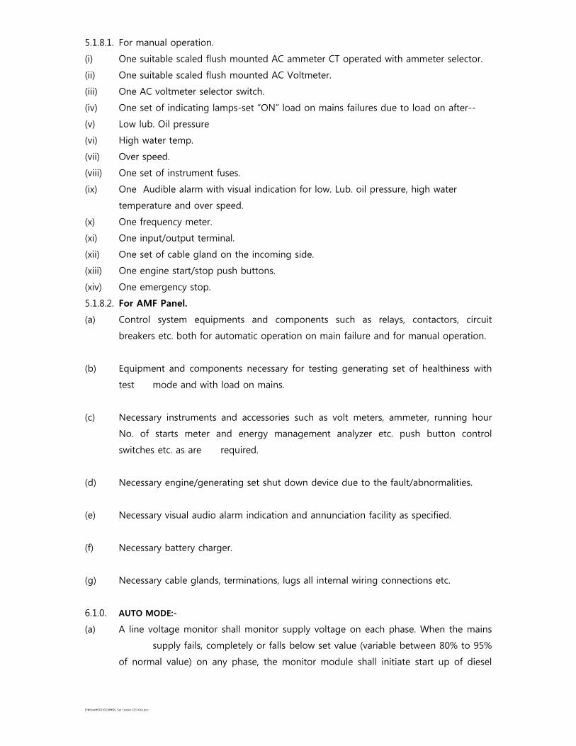
5.1.8.1. For manual operation.
(i) One suitable scaled flush mounted AC ammeter CT operated with ammeter selector.
(ii) One suitable scaled flush mounted AC Voltmeter.
(iii) One AC voltmeter selector switch.
(iv) One set of indicating lamps-set “ON” load on mains failures due to load on after--
(v) Low lub. Oil pressure
(vi) High water temp.
(vii) Over speed.
(viii) One set of instrument fuses.
(ix) One Audible alarm with visual indication for low. Lub. oil pressure, high water
temperature and over speed.
(x) One frequency meter.
(xi) One input/output terminal.
(xii) One set of cable gland on the incoming side.
(xiii) One engine start/stop push buttons.
(xiv) One emergency stop.
5.1.8.2. For AMF Panel.
(a) Control system equipments and components such as relays, contactors, circuit
breakers etc. both for automatic operation on main failure and for manual operation.
(b) Equipment and components necessary for testing generating set of healthiness with
test mode and with load on mains.
(c) Necessary instruments and accessories such as volt meters, ammeter, running hour
No. of starts meter and energy management analyzer etc. push button control
switches etc. as are required.
(d) Necessary engine/generating set shut down device due to the fault/abnormalities.
(e) Necessary visual audio alarm indication and annunciation facility as specified.
(f) Necessary battery charger.
(g) Necessary cable glands, terminations, lugs all internal wiring connections etc.
6.1.0. AUTO MODE:-
(a) A line voltage monitor shall monitor supply voltage on each phase. When the mains
supply fails, completely or falls below set value (variable between 80% to 95%
of normal value) on any phase, the monitor module shall initiate start up of diesel

D:\cbse\20130228\DG Set Tender 315 KVA.doc
engine. To avoid Initiation due to momentary dips/system disturbance, a time delay
adjustable between 0 to 5 seconds shall be incorporated in the start up initiation.
(b) A three attempt starting facility shall be provided 6 seconds ON, 5 seconds OFF, 6
seconds ON, 5 seconds OFF and 6 seconds ON if at the end of the third
attempt the engine does not start, it shall be locked out of start and a master timer
shall be provide for this function. Suitable adjustment timers are to be incorporated
which will make it feasible to vary independently ON-OFF setting periods from 1-10
seconds. If alternator does not build up voltage after the first or second start as may
be, further starting attempt will not be made until the starting facility is reset.
(c) Once the alternator has built up voltage, the alternator contactor or circuit breaker
shall close connection load to the alternator. The load is now supplied by the
alternator.
(d) When the main supply is restored and healthy as sensed by the line voltage monitor
setting both for under voltage and unbalance, the system shall be mentioned by a
suitable timer which can be set between 1 minute to 10 minutes for the load to be
transferred automatically to main supply.
(e) The diesel alternator set reverts to standby for next operation as per (a), (b) and (c)
above.
(f) Alternator and mains ACB are invariably electrically interlocked so that unless one is
off the other can not be made on.
6.2.0. MANUAL MODE:-
(a) In a manual mode it shall be feasible to start up the generator set only by the
operator pressing the start push button.
(b) Three attempt starting facility shall be operative for the start-up to function.
(c) Alternator circuit breaker closing and trip operations shall be also through operator
only by pressing the appropriate button on the panel and closure shall be feasible
only after alternator has built up full voltage. If the load is already on ‘mains’ pressure
on “close” button shall be ineffective.
(d) Engine shut down, otherwise due to faults, shall be manual, by pressing a “stop”
button.
D:\cbse\20130228\DG Set Tender 315 KVA.doc
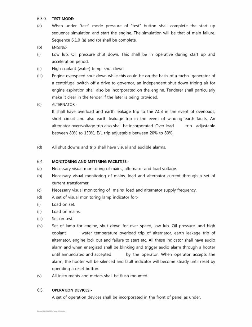
6.3.0. TEST MODE:-
(a) When under “test” mode pressure of “test” button shall complete the start up
sequence simulation and start the engine. The simulation will be that of main failure.
Sequence 6.1.0 (a) and (b) shall be complete.
(b) ENGINE:-
(i) Low lub. Oil pressure shut down. This shall be in operative during start up and
acceleration period.
(ii) High coolant (water) temp. shut down.
(iii) Engine overspeed shut down while this could be on the basis of a tacho generator of
a centrifugal switch off a drive to governor, an independent shut down triping air for
engine aspiration shall also be incorporated on the engine. Tenderer shall particularly
make it clear in the tender if the later is being provided.
(c) ALTERNATOR:-
It shall have overload and earth leakage trip to the ACB in the event of overloads,
short circuit and also earth leakage trip in the event of winding earth faults. An
alternator over/voltage trip also shall be incorporated. Over load trip adjustable
between 80% to 150%, E/L trip adjustable between 20% to 80%.
(d) All shut downs and trip shall have visual and audible alarms.
6.4. MONITORING AND METERING FACILITIES:-
(a) Necessary visual monitoring of mains, alternator and load voltage.
(b) Necessary visual monitoring of mains, load and alternator current through a set of
current transformer.
(c) Necessary visual monitoring of mains, load and alternator supply frequency.
(d) A set of visual monitoring lamp indicator for:-
(i) Load on set.
(ii) Load on mains.
(iii) Set on test.
(iv) Set of lamp for engine, shut down for over speed, low lub. Oil pressure, and high
coolant water temperature overload trip of alternator, earth leakage trip of
alternator, engine lock out and failure to start etc. All these indicator shall have audio
alarm and when energized shall be blinking and trigger audio alarm through a hooter
until annunciated and accepted by the operator. When operator accepts the
alarm, the hooter will be silenced and fault indicator will become steady until reset by
operating a reset button.
(v) All instruments and meters shall be flush mounted.
6.5. OPERATION DEVICES:-
A set of operation devices shall be incorporated in the front of panel as under.
D:\cbse\20130228\DG Set Tender 315 KVA.doc
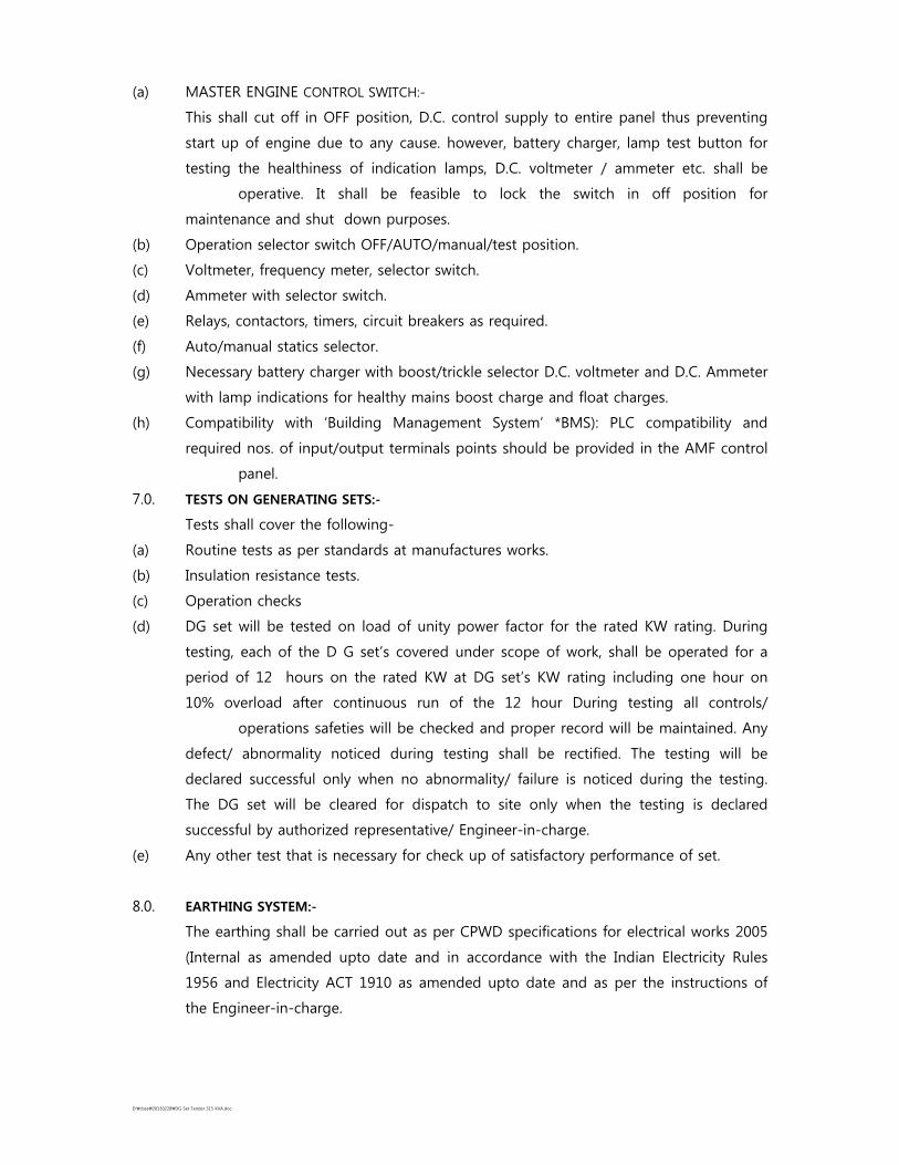
(a) MASTER ENGINE CONTROL SWITCH:-
This shall cut off in OFF position, D.C. control supply to entire panel thus preventing
start up of engine due to any cause. however, battery charger, lamp test button for
testing the healthiness of indication lamps, D.C. voltmeter / ammeter etc. shall be
operative. It shall be feasible to lock the switch in off position for
maintenance and shut down purposes.
(b) Operation selector switch OFF/AUTO/manual/test position.
(c) Voltmeter, frequency meter, selector switch.
(d) Ammeter with selector switch.
(e) Relays, contactors, timers, circuit breakers as required.
(f) Auto/manual statics selector.
(g) Necessary battery charger with boost/trickle selector D.C. voltmeter and D.C. Ammeter
with lamp indications for healthy mains boost charge and float charges.
(h) Compatibility with ‘Building Management System’ *BMS): PLC compatibility and
required nos. of input/output terminals points should be provided in the AMF control
panel.
7.0. TESTS ON GENERATING SETS:-
Tests shall cover the following-
(a) Routine tests as per standards at manufactures works.
(b) Insulation resistance tests.
(c) Operation checks
(d) DG set will be tested on load of unity power factor for the rated KW rating. During
testing, each of the D G set’s covered under scope of work, shall be operated for a
period of 12 hours on the rated KW at DG set’s KW rating including one hour on
10% overload after continuous run of the 12 hour During testing all controls/
operations safeties will be checked and proper record will be maintained. Any
defect/ abnormality noticed during testing shall be rectified. The testing will be
declared successful only when no abnormality/ failure is noticed during the testing.
The DG set will be cleared for dispatch to site only when the testing is declared
successful by authorized representative/ Engineer-in-charge.
(e) Any other test that is necessary for check up of satisfactory performance of set.
8.0. EARTHING SYSTEM:-
The earthing shall be carried out as per CPWD specifications for electrical works 2005
(Internal as amended upto date and in accordance with the Indian Electricity Rules
1956 and Electricity ACT 1910 as amended upto date and as per the instructions of
the Engineer-in-charge.

D:\cbse\20130228\DG Set Tender 315 KVA.doc
8.1. ACOUSTIC ENCLOSURE CONSTRUCTION DETAILS:-
The enclosure shall be fabricated using CRCA sheets of 14 SWG thickness and steel
member The enclosure shall have suitable cross members to make it robust and
sturdy. Rock wool /mineral wool of suitable thickness and density conforming to IS
8183 shall be used for acoustic insulation to reduce the sound level to 75 dBA
from the original sound level of 120-130 dBA when measured at one meter distance
from the D.G. set. The acoustic enclosure shall consist of following –
A. Acoustic Insulation:-
High density fireproof acoustic enclosure material i.e. resinbonded rock wool/mineral
wool (100mm thick of 64 Kg 3 per Cu. M density) conforming to IS: 8183 is provided
on all doors and roof to absorb noise. The insulation material used is fire retardant
the insulation shall be covered with fiber glass cloth and shall be supported by
perforated sheet. Sound attenuators /down stream silencers shall be provided at all
openings for air inlet / outlet to facilitate free air flow but to absorb sound
resulting in extremely low noise level. Detachable partitions shall be provided inside
the enclosure to attain further noise attenuation of the engine.
B. Fabrication & Design :-
Fabrication and design of enclosure is to be got approved from the department,
before actual fabrication. The enclosure shall be as per standard / design approved
by engine manufacturer and shall also confirm to requirements of bye-laws.
Emergency shut off switch is required out side the acoustic enclosure for switching off
D.G. set in case of emergency alongwith an audio signal alarm. At least three No. of
twin luminare fittings with lamp & wiring are also to be installed in the acoustic
enclosure.
C. Noise Suppressor:-
A suitable designed absorption type residential noise suppressor shall be provided
which minimizes the exhaust noise of the engine.
D. Exhaust System:-
The exhaust gas shall be taken out through a specially designed flexible pipe, which
prevents any back pressure on the engine.
E. Thermal Insulation:-
The exhaust system and noise suppressor shall be provided thermal insulation by
using glass wool & covering it with aluminium sheet. This prevents it from radiating
excess heat on the engine, make it safe for the operator and enhances asthetics.
F. Surface Treatment:-
The enclosure shall be surface treated and painting with high quality polyurethane
epoxy paint with prior zinc oxide primer base, which make it weather proof and

D:\cbse\20130228\DG Set Tender 315 KVA.doc
suitable for outdoor application. The paint shall be highly resistant to acids, alkalies,
salt sprays, halogens, solvents, lubricants etc. and shall be very good dielectric
properties and is resistant to abrasion and cracking.
G. Air Circulation & Ventilation System:-
A suitable forced air circulation and ventilation system designed to maintain safe
operating temperatures inside the enclosure. Requisite air circulation for engine
aspiration combustion and cooling shall be provided by means of exhaust fans and
tube axial flow blower driven by a 3 phase squirrel cage induction motor. The
temperature in side the enclosure should not increase beyond the permissible limit.
H. Vibration Insulation:-
The engine and alternator shall be mounted on anti-vibration mounting pads to
eliminate engine vibration.
I. Hardware:-
Inlet and outlet for cable, draining of lub oil and diesel etc. shall be provided. Heavy
duty bronze industrial pressure locking system shall be provided. The doors shall be
gasketed with high quality EPDN gaskets to avoid leakage of sound.
J. The firm must furnish a copy norms as below:-
-- Exhaust norms of engine offered shall be minimum euro-II/ bharat-III
-- Acoustic Enclosure type test
The test must be carried out through a test lab., which is accredited by CPCB for this
purpose.
K. The acoustic enclosure shall be as per standard design of D.G. set OEA/OEM and shall
also confirm requirement of bye-laws of CPCB. Sound level when measured at a
distance of 1mtr. Should not exceed 75db. Adequate illumination inside the enclosure
shall be provided.
L. Payment of all taxes such as work contract tax and VAT (except service tax etc.) shall
be the liability of the contractor and nothing shall be paid on this account
however service tax is reimbursable on production of proof of payment and service
tax for this work.
D:\cbse\20130228\DG Set Tender 315 KVA.doc
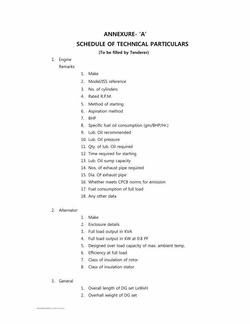
ANNEXURE- ‘A’
SCHEDULE OF TECHNICAL PARTICULARS
(To be filled by Tenderer)
1. Engine
Remarks
1. Make
2. Model/ISS reference
3. No. of cylinders
4. Rated R.P.M.
5. Method of starting
6. Aspiration method
7. BHP
8. Specific fuel oil consumption (gm/BHP/Hr.)
9. Lub. Oil recommended
10. Lub. Oil pressure
11. Qty. of lub. Oil required
12. Time required for starting
13. Lub. Oil sump capacity
14. Nos. of exhaust pipe required
15. Dia. Of exhaust pipe
16. Whether meets CPCB norms for emission
17. Fuel consumption of full load
18. Any other data
2. Alternator
1. Make
2. Enclosure details
3. Full load output in KVA
4. Full load output in KW at 0.8 PF
5. Designed over load capacity of max. ambient temp.
6. Efficiency at full load
7. Class of insulation of rotor
8. Class of insulation stator
3. General
1. Overall length of DG set LxWxH
2. Overhall weight of DG set

D:\cbse\20130228\DG Set Tender 315 KVA.doc
3. Noise level of DG set at one meter with acoustic enclosure
4. AMF panels
1. Make
2. Type (Floor/Wall mounted)
3. Overall dimensions (LxBXH)
4. Finish
5. Generator Control Panel
1. Make
6. Acoustic Enclosure
1. Make
2. Size
3. Details of acoustic lining material & make
D:\cbse\20130228\DG Set Tender 315 KVA.doc
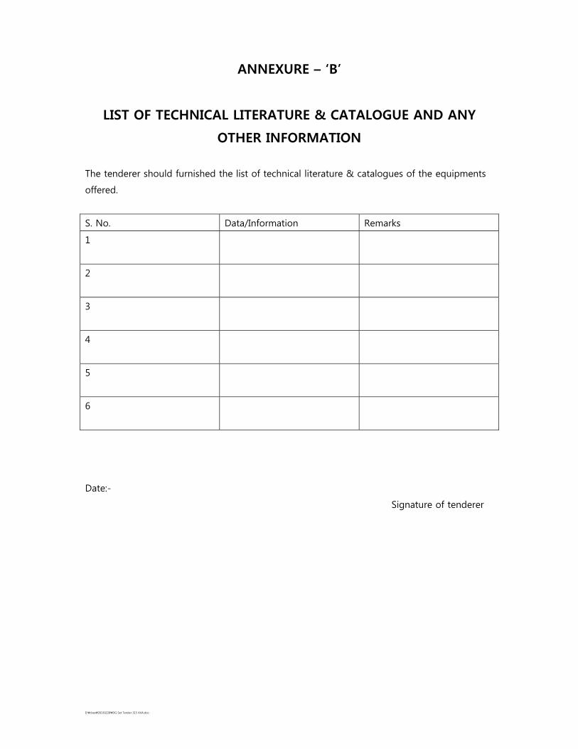
ANNEXURE – ‘B’
LIST OF TECHNICAL LITERATURE & CATALOGUE AND ANY
OTHER INFORMATION
The tenderer should furnished the list of technical literature & catalogues of the equipments
offered.
S. No. Data/Information Remarks
1
2
3
4
5
6
Date:-
Signature of tenderer

D:\cbse\20130228\DG Set Tender 315 KVA.doc
Name of Work: SITC of 315 KVA Silent Type D.G. Set for CBSE HQ, bldg. Preet Vihar, Delhi-110092 (SH: SITC of 1 No. 315 KVA Silent Type DG Set with AMF Panel).
S.No.
Description of work Qty. Rate Unit Amount Remarks
1(i) A) B)
Providing installation, Testing and
commissioning of 'Silent Type Diesel
Generating set along with Prime Power
Rating of 315 KVA, 415 volts at 1500
RPM, 0.8 lagging power factor at 415 V
suitable for 50 Hz, 3 Phase system & for
0.85 Load factor and consisting of the
following:
Diesel Engine:
Diesel engine 4 stroke water cooled,
electric start, of suitable BHP at 1500
RPM suitable FOR ABOVE OUTPUT OF
ALTERNATOR AT 40 Degree C, 50% RH
& at 1000 Meter MSL and conforming
to BS 5514, BS. 649, IS 10000, capable of
taking 10% over loading for one hour in
any period of 12 hours of continous
operation. The engine will be fitted
complete with all the required
accessories.
Engine mounted instrument panel fitted with
and having digital display for following:
(i) Start-stop switch with key
(ii) Water temperature indication
(iii) Lubrication oil pressure indication
(iv) Lubrication oil temperature
indication
(v) Battery Charging indication
(vi) RPM indication
(vii) Over speed Indication
(viii) Low lub. Oil trip indication
(ix) Engine Hours indication
D:\cbse\20130228\DG Set Tender 315 KVA.doc
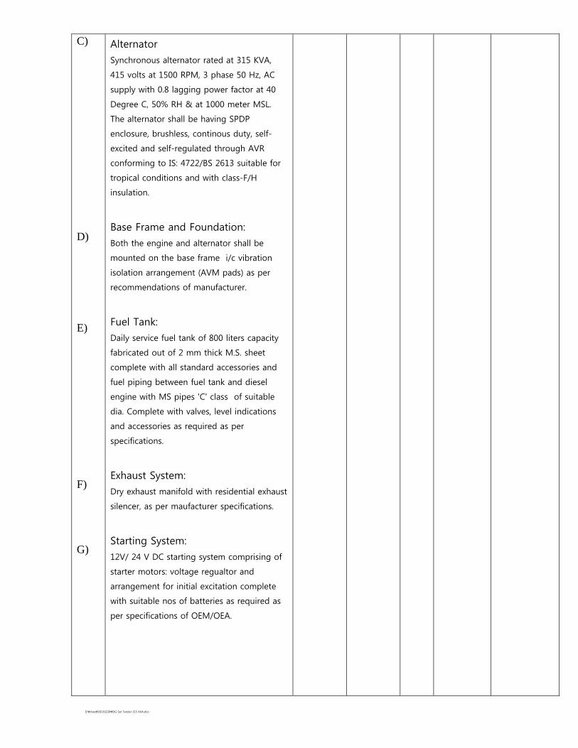
C) D) E) F) G)
Alternator
Synchronous alternator rated at 315 KVA,
415 volts at 1500 RPM, 3 phase 50 Hz, AC
supply with 0.8 lagging power factor at 40
Degree C, 50% RH & at 1000 meter MSL.
The alternator shall be having SPDP
enclosure, brushless, continous duty, self-
excited and self-regulated through AVR
conforming to IS: 4722/BS 2613 suitable for
tropical conditions and with class-F/H
insulation.
Base Frame and Foundation:
Both the engine and alternator shall be
mounted on the base frame i/c vibration
isolation arrangement (AVM pads) as per
recommendations of manufacturer.
Fuel Tank:
Daily service fuel tank of 800 liters capacity
fabricated out of 2 mm thick M.S. sheet
complete with all standard accessories and
fuel piping between fuel tank and diesel
engine with MS pipes 'C' class of suitable
dia. Complete with valves, level indications
and accessories as required as per
specifications.
Exhaust System:
Dry exhaust manifold with residential exhaust
silencer, as per maufacturer specifications.
Starting System:
12V/ 24 V DC starting system comprising of
starter motors: voltage regualtor and
arrangement for initial excitation complete
with suitable nos of batteries as required as
per specifications of OEM/OEA.
D:\cbse\20130228\DG Set Tender 315 KVA.doc
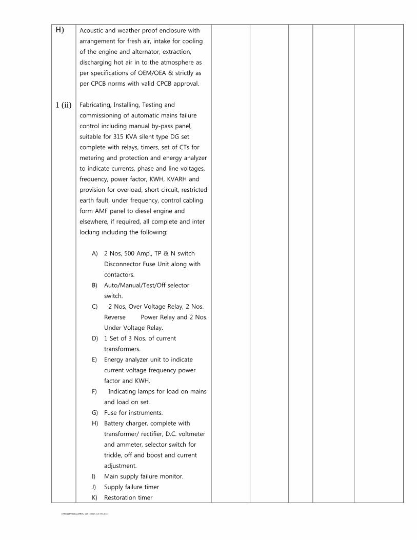
H) 1 (ii)
Acoustic and weather proof enclosure with
arrangement for fresh air, intake for cooling
of the engine and alternator, extraction,
discharging hot air in to the atmosphere as
per specifications of OEM/OEA & strictly as
per CPCB norms with valid CPCB approval.
Fabricating, Installing, Testing and
commissioning of automatic mains failure
control including manual by-pass panel,
suitable for 315 KVA silent type DG set
complete with relays, timers, set of CTs for
metering and protection and energy analyzer
to indicate currents, phase and line voltages,
frequency, power factor, KWH, KVARH and
provision for overload, short circuit, restricted
earth fault, under frequency, control cabling
form AMF panel to diesel engine and
elsewhere, if required, all complete and inter
locking including the following:
A) 2 Nos, 500 Amp., TP & N switch
Disconnector Fuse Unit along with
contactors.
B) Auto/Manual/Test/Off selector
switch.
C) 2 Nos, Over Voltage Relay, 2 Nos.
Reverse Power Relay and 2 Nos.
Under Voltage Relay.
D) 1 Set of 3 Nos. of current
transformers.
E) Energy analyzer unit to indicate
current voltage frequency power
factor and KWH.
F) Indicating lamps for load on mains
and load on set.
G) Fuse for instruments.
H) Battery charger, complete with
transformer/ rectifier, D.C. voltmeter
and ammeter, selector switch for
trickle, off and boost and current
adjustment.
I) Main supply failure monitor.
J) Supply failure timer
K) Restoration timer

D:\cbse\20130228\DG Set Tender 315 KVA.doc
L) Control unit with three impulse
automatic engine start/ stop and
failure to start lockout.
M) Impulse counter with locking and
reset facility.
N) ON/OFF/ Control circuit switch with
indicator.
Audio/Video annunciaton for :
(i) High water temperature
(ii) Low lubricating oil pressure
(iii) Engine over speed
(iv) Engine fails to start
(v) Full load/maximum load wiring
1 Set Set
2) Supplying and laying of two nos. XLPE/ PVC
insulated and PVC sheathed Al. conductor
armoured power cable of 1.1 KV grade of
size 3-1/2 x 300 sq.mm in the existing
masonary open duct as required.
130 Mtr. Mtr.
3) Supplying and making end termination brass
compression gland and Al lugs for 2 nos., 3-
1/2 x300 sqm XLPE Al conductor cable of
1.1 KV grade etc. as required.
12 Set Set
4) Earthing with copper earth plate 600 m x 600
mm x 3 m thick including accessories, and
providing masonary enclosure with cover
plate having locking arrangement and
watering pipe of 2.7 metre long etc. with
charcoal/coake and salt as required.
4 set Set

D:\cbse\20130228\DG Set Tender 315 KVA.doc
5) Providing and fixing 25 mm X 5 mm copper
strip in 40 mm dia G.I. pipe from earth
electrode including connection with brass
nut, bolt, spring, washer excavation and re-
filling etc. as required.
60 Mtr. Mtr.
6) P&F 25 m x 5 mm copper strip on surface or
in recess for connectors etc. as required.
15 Mtr. Mtr.
Total Add 3% Contingencies
Grand Total Say Rs.
Signature of the Agency with
Complete address and seal
Telephone______________
Mobile No.________________