single user or multiple user - ieee web hosting
TRANSCRIPT

Single User or Multiple User ?
Speaker: Xiao [email protected]
Dept. Electronics and Comm. Eng.Sun Yat-sen University
March 19, 2013
Xiao Ma (SYSU) Coding Group Guangzhou, February 2013 1 / 80

Outline
1 Single- and Multi-User Communication
2 Superposition Coded Modulation
3 Kite Codes
4 Block Markov Superposition Transmission
5 Conclusions
Xiao Ma (SYSU) Coding Group Guangzhou, February 2013 2 / 80

Outline
1 Single- and Multi-User Communication
2 Superposition Coded Modulation
3 Kite Codes
4 Block Markov Superposition Transmission
5 Conclusions
Xiao Ma (SYSU) Coding Group Guangzhou, February 2013 3 / 80

Single-User Communication System
C. E. Shannon,“A mathematical theory of communication,”BellSys. Tech. Journal, 27, 379-423, 623-656, 1948.
Digital Communication Framework
encoder decoderchannel
noise
source sink
Figure: Block diagram of communication system.
A source is nothing more than and nothing less than an arbitrary randomprocess;
The task of the encoder is to transform the output from the source intosignals that matched to the channel, which can be split into two parts:
Source encoder: Everything is binary!Channel encoder: Key techniques in the physical layer.
A channel transforms an input to an output in a random manner dominatedby a probability transition law.
Xiao Ma (SYSU) Coding Group Guangzhou, February 2013 4 / 80

Single-User Communication System
Shannon showed that a channel can be characterized by a parameter, C , calledthe channel capacity, which is a measure of how much information the channelcan convey.
The Channel Coding Theorem
codes exist that provide“reliable”communication provided that the code ratesatisfies R < C ;
conversely, if R > C , there exists no code that provides reliablecommunication.
Xiao Ma (SYSU) Coding Group Guangzhou, February 2013 5 / 80

Single-User Communication System
Capacity of the Ideal AWGN Channel
Consider the discrete-time channel model,
Yt = Xt + Zt ,
where E [X 2
t ] < P and Zt ∼ (0, σ2).
The capacity of the channel is given by
C =1
2log2(1 +
P
σ2) bits/channel symbol.
Frequently, one is interested in a channel capacity in units of bits per secondrather than bits per channel symbol,
C =W log2(1 +P
σ2) bits/second.
Xiao Ma (SYSU) Coding Group Guangzhou, February 2013 6 / 80

Single-User Communication System
−10 −5 0 5 10 15 20 25 30 350
1
2
3
4
5
6
7
8
9
SNR [dB]
Cap
acity
(bits
/sym
bol)
1.53 dB
256QAM
128QAM
64QAM
32QAM
16QAM
8PSK
QPSK
C = log(1 + SNR)
Figure: Capacity versus SNR curves for selected modulation schemes.
Xiao Ma (SYSU) Coding Group Guangzhou, February 2013 7 / 80

Power Efficiency
Traditional CodesHamming codes, Golay codes, Reed-Muller codes
Bose-Chaudhuri-Hocquenghem codes, Reed-Solomon codes
Convolutional Codes
Capacity-Approaching Codes
Turbo codes
Low-density parity-check (LDPC) codes
Repeat-accumulate codes
Accumulate-repeat-accumulate codes
Concatenated zigzag codes, concatenated tree codes
Precoded concatenated zigzag codes
Convolutional LDPC codes
Polar codes
Xiao Ma (SYSU) Coding Group Guangzhou, February 2013 8 / 80

Bandwidth Efficiency
Existing Coded Modulation Schemes
Trellis-coded modulation (TCM): proposed by Ungerboeck in 1982;
Bit-interleaved coded modulation (BICM): proposed by Zehavi in 1992 forcoding for fading channels;
Multilevel codes (MLC): first proposed by H. Imai in 1977.
Capacity-Approaching Coded Modulation Schemes
Turbo-TCM schemes: two (or multiple) TCM codes are concatenated in thesame fashion as binary turbo codes
BICM with iterative decoding
The output stream of a binary (turbo or LDPC) encoder is bit-interleaved andthen mapped to an M-ary constellationThe de-mapper is viewed as a APP decoder
MLC with iterative multistage decoding
Superimposed binary codes
Coded modulation using non-binary LDPC codes
Xiao Ma (SYSU) Coding Group Guangzhou, February 2013 9 / 80

Typical Multi-User Channels
Multiple-Access Channel
x1
x2
xm
y
)...,
,,|( 21
mx
xxyp
two (or more) senders send information toa common receiver;
senders must contend not only with thereceiver noise but with interference fromeach other as well.
Broadcast Channely1
y2
ym
x)|
,..,,( 21
xy
yyp
m
one sender send information to two ormore receivers;
the basic problem is to find the set ofsimultaneously achievable rates forcommunication.
Xiao Ma (SYSU) Coding Group Guangzhou, February 2013 10 / 80
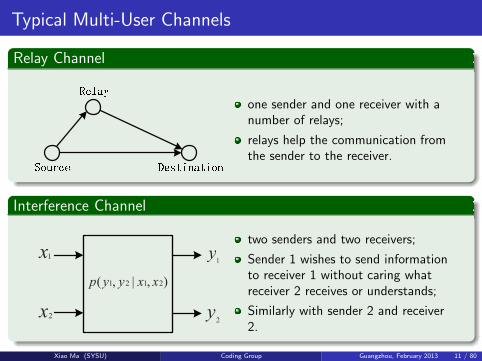
Typical Multi-User Channels
Relay Channel
one sender and one receiver with anumber of relays;
relays help the communication fromthe sender to the receiver.
Interference Channel
x1
x2
),|,( 2121 xxyyp
y1
y2
two senders and two receivers;
Sender 1 wishes to send informationto receiver 1 without caring whatreceiver 2 receives or understands;
Similarly with sender 2 and receiver2.
Xiao Ma (SYSU) Coding Group Guangzhou, February 2013 11 / 80

Typical Multi-User Channels
Two-Way Channel
x1 x2
),|,( 2121 xxyyp
y1
y2
The two-way channel is very similar to the interference channel;
Sender 1 is attached to receiver 2 and sender 2 is attached to receiver 1;
This channel introduces another fundamental aspect of network informationtheory: namely, feedback;
Feedback enables the senders to use the partial information that each hasabout the other’s message to cooperate with each other.
QuestionCan we apply the strategies in the multi-user communication system to thesingle-user communication system?
Xiao Ma (SYSU) Coding Group Guangzhou, February 2013 12 / 80

Outline
1 Single- and Multi-User Communication
2 Superposition Coded Modulation
3 Kite Codes
4 Block Markov Superposition Transmission
5 Conclusions
Xiao Ma (SYSU) Coding Group Guangzhou, February 2013 13 / 80

Superposition Coded Modulation
Gaussian Multiple-Access ChannelTwo senders, X1 and X2, communicate to thesingle receiver, Y . The received signal at timet is
Yt = X1t + X2t + Zt ,
where Zt ∼ (0,N );
We assume that there is a power constraintPj on sender j .
Interpretation of the Corner Points
Point A: the maximum rate achievable C (P1
N) from sender 1 to the receiver
when sender 2 is not sending any information.
Point B: decoding as a two-stage process
The receiver decodes the second sender, considering the first sender as part ofthe noise. This decoding will have low probability of error if R2 < C ( P2
P1+N);
After the second sender has been decoded successfully, it can be subtractedout and the first sender can be decoded correctly if R1 < C (P1
N).
Points C and D correspond to B and A, respectively, with the roles of thesenders reversed.
Xiao Ma (SYSU) Coding Group Guangzhou, February 2013 14 / 80
Superposition Coded Modulation
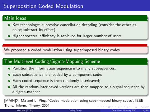
Main Ideas
Key technology: successive cancellation decoding (consider the other asnoise; subtract its effect);
Higher spectral efficiency is achieved for larger number of users.
We proposed a coded modulation using superimposed binary codes.
The Multilevel Coding/Sigma-Mapping Scheme
Partition the information sequence into many subsequences;
Each subsequence is encoded by a component code;
Each coded sequence is then randomly-interleaved;
All the random-interleaved versions are then mapped to a signal sequence bya sigma-mapper
[MA04]X. Ma and Li Ping, “Coded modulation using superimposed binary codes”, IEEE
Trans. Inform. Theory, 2004Xiao Ma (SYSU) Coding Group Guangzhou, February 2013 15 / 80

Multilevel Coding/Sigma-Mapping Scheme
Multilevel Coding/Sigma-Mapping Scheme
Component codes: turbo-like codes or LDPC codes;
Power-allocation strategy:
A simulation-based recursive search algorithm;Gaussian approximation power allocation.
Xiao Ma (SYSU) Coding Group Guangzhou, February 2013 16 / 80

Multilevel Coding/Sigma-Mapping Scheme
Normal Graph
Figure: A normal graph for the multilevel coding/sigma-mapping scheme.
Decoding
three kinds of nodes: C ,∏
and∑
;
messages are processed and exchanged over the normal graph.
Xiao Ma (SYSU) Coding Group Guangzhou, February 2013 17 / 80

Simulation Result
Using ten Brink’s doped code of length 500000 as component codes.
Figure: Performance of the four-level coding/sigma-mapping system with coding rate of2 bits/dim.
Xiao Ma (SYSU) Coding Group Guangzhou, February 2013 18 / 80
Summary
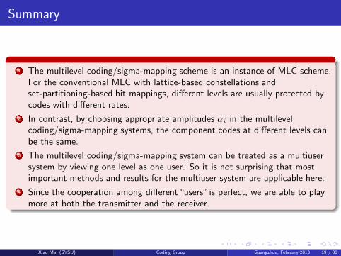
1 The multilevel coding/sigma-mapping scheme is an instance of MLC scheme.For the conventional MLC with lattice-based constellations andset-partitioning-based bit mappings, different levels are usually protected bycodes with different rates.
2 In contrast, by choosing appropriate amplitudes αi in the multilevelcoding/sigma-mapping systems, the component codes at different levels canbe the same.
3 The multilevel coding/sigma-mapping system can be treated as a multiusersystem by viewing one level as one user. So it is not surprising that mostimportant methods and results for the multiuser system are applicable here.
4 Since the cooperation among different“users” is perfect, we are able to playmore at both the transmitter and the receiver.
Xiao Ma (SYSU) Coding Group Guangzhou, February 2013 19 / 80

Outline
1 Single- and Multi-User Communication
2 Superposition Coded Modulation
3 Kite Codes
4 Block Markov Superposition Transmission
5 Conclusions
Xiao Ma (SYSU) Coding Group Guangzhou, February 2013 20 / 80

Time Varying Channels
Gaussian Broadcast ChannelsA sender of power P and two distant receivers;
Y1 = X + Z1 and Y2 = X + Z2, where Z1 and Z2 are arbitrarily correlatedGaussian random variables with variances N1 and N2, respectively.
Assume that N1 < N2. That is, the receiver Y1 sees a better channel. Themessage consists of“common”information for both users and privateinformation for Y1.
The results of the broadcast channel can be applied to the case of asingle-user channel with an unknown distribution.
The objective is to get at least the minimum information through when thechannel is bad and to get some extra information through when the channelis good.
Time Varying Channels
different channel states at different time;
adaptive coding scheme: rateless coding.
Xiao Ma (SYSU) Coding Group Guangzhou, February 2013 21 / 80

Rateless Coding
A coding method that can generate potentially infinite parity bits for any givenfixed-length sequence.
Existing Rateless Codes
LT-codes;
Raptor codes.
...
MotivationsRaptor codes are optimized by degree distribution for erasure channels;
No universal degree distributions exist for AWGN channels.
How to construct good codes for AWGN channels with arbitrarily designatedcoding rate?
We will propose a class of rateless codes for AWGN channels.
Xiao Ma (SYSU) Coding Group Guangzhou, February 2013 22 / 80

Kite Codes
An ensemble of Kite codes with dimension k , denoted by K [∞, k ; p], is specifiedby a real sequence p, called p-sequence.
Encoder of Kite Codesc = (v0, · · · , vk−1,w0,w1, · · · ,wt , · · · )
������ �� �� � ���
�� � � �� �������� � ����� �� ��� �
�������� � ����������� �� ��� ����� �� �� �����
�������� �� ���� ��� ��� �������
����
!"#
$
$
%&'( )) *+,-
./
0!
Initially, load information sequenceof length k into a buffer.
At time t > 0, randomly choose,with success probability pt , severalbits from the buffer.
Calculate the XOR of these chosenbits and use it to drive theaccumulator to generate a parity bitwt .
Xiao Ma (SYSU) Coding Group Guangzhou, February 2013 23 / 80

Decoder of Kite Codes
For any given n ≥ k , the prefix code with length n of a Kite code K [∞, k ; p] isdenoted by K [n , k ] and also called Kite code.
From the encoding process of Kite codes, we can see that the parity-check matrixof Kite codes has the following form.
1
1
1
1
1
1
1
1
1
1
1
1
1
1 1
1
1
1
1
1
1
1
1
1
1
1
1
1
1
1 1
1
11
1 1
1 1
By choosing pt ≪ 0.5, we can construct Kite codes as LDPC codes. If so, thereceiver can perform the iterative sum-product decoding algorithm.
Xiao Ma (SYSU) Coding Group Guangzhou, February 2013 24 / 80

Relations Between Kite Codes and Existing Codes
A specific Kite code (a realization of Kite code) is a kind of LDPC code, which isclosely related to generalized IRA code.
A specific Kite code can also be considered as a partially serially concatenatedcode with a systematic LDGM code as outer code and an accumulator as an innercode.
However, as an ensemble, Kite codes are new.
Xiao Ma (SYSU) Coding Group Guangzhou, February 2013 25 / 80

Relations Between Codes Ensembles
A binary linear code ensemble is a probability space (C,Q )–a sample space C anda probability assignment Q (C) to each C ∈ C. Each sample C ∈ C is a binarylinear code, and the probability Q (C) is usually implicitly determined by a randomconstruction method.
1 Code ensemble Cg : random generator matrix G of size k × n.2 Code ensemble Ch : random parity-check matrix H of size (n − k ) × n.3 Code ensemble Cs : random parity-check matrix Hs = [P , In−k ].
Xiao Ma (SYSU) Coding Group Guangzhou, February 2013 26 / 80

Kite code is new as an ensemble
An ensemble of Kite codes (of length n) with pt < 1/2 has the same sample spaceas that of Cs but different probability assignment to each code.
An ensemble of general LDPC code is specified by the a pair of degree distributions
λ(x ) =∑
λixi and ρ(x ) =
∑
ρixi ,
where λi and ρi are fractions. Given λi > 0, there must exist nodes of degree i .
These fractions are fixed.
An ensemble of Kite code is specified by the p-sequence. Its degree distributionsare
λ(x ) =∑
λixi and ρ(x ) =
∑
ρixi ,
where λi and ρi are probabilities. Even if λi > 0, it is possible for a specific Kitecode to have no nodes of degree i .
Xiao Ma (SYSU) Coding Group Guangzhou, February 2013 27 / 80

Design of Kite Code
Original Problem
Evidently, the performance of Kite codes is determined by the p-sequence. Thewhole p-sequence should be optimized jointly such that all the prefix codes of Kitecodes are good enough, which is too complex to implement.
2 2
2
2
2
2
2
2
2
2
2
2
2
2
2
2
2 2
2
22
2 2
2 2
34
56
78
Too complex due to too many (may be infinite) variables involved in.
Xiao Ma (SYSU) Coding Group Guangzhou, February 2013 28 / 80

Design of Kite Code: A Simple Idea (layer by layer)
Partitioning the coding rate into 9 subintervals.
9 9
99
9 9
9
9
9
9
9
9
99
9
9
9
9
9
9
9
99
99
9
9
9
99
9
9
9 99
999 99 9
99
99
9
9
99
:;< = >
?@A B C
DEF G H
Firstly, we choose q9 such that theprefix code K [⌊k/0.9⌋, k ] is as goodas possible.
Secondly, we choose q8 with fixedq9 such that the prefix codeK [⌊k/0.8⌋, k ] is as good as possible.
Thirdly, we choose q7 with fixed(q9, q8) such that the prefix codeK [⌊k/0.7⌋, k ] is as good as possible.
· · ·we choose q1 with fixed(q9, q8, · · · , q2) such that the prefixcode K [⌊k/0.1⌋, k ] is as good aspossible.
At each step, it is a one-dimensional optimization problem and can beimplemented with density evolution or simulations.
Xiao Ma (SYSU) Coding Group Guangzhou, February 2013 29 / 80

Numerical Results
With data length k = 1890 and rates from 0.1 to 0.9, we have the following curves.
−6 −4 −2 0 2 4 6 810
−7
10−6
10−5
10−4
10−3
10−2
10−1
100
SNR (Signal−to−Noise−Ratio) = 10log10
(1/σ2) [dB]
BE
R (
Bit−
Err
or−
Rat
e)
Issue: Error floors.
[MA11]X. Ma et al, “Serial Concatenation of RS Codes with Kite Codes: Performance
Analysis, Iterative Decoding and Design”, http://arxiv.org/abs/1104.4927, 2011
[BAI11]B. Bai, B. Bai, X. Ma,“Semi-random Kite Codes over Fading Channels”, AINA
2011Xiao Ma (SYSU) Coding Group Guangzhou, February 2013 30 / 80

Numerical Results (continued)
With k = 50000, we utilize RS code as outer codes to lower down the error floor.
−6 −4 −2 0 2 4 6 8 10 120.1
0.2
0.3
0.4
0.5
0.6
0.7
0.8
0.9
1
SNR [dB]
rate
[bits
/BP
SK
]
capacitysimulation results
Issue: Relative large gap between the performance and the Shannon limits.
Xiao Ma (SYSU) Coding Group Guangzhou, February 2013 31 / 80

Improved Design of Kite Codes
1 Issue I: In the high-rate region, there exist error floors, which is caused by theexistence of all-zero (or extremely-low-weight) columns in the randomlygenerated matrix Hv .
2 Issue II: In the low-rate region, there exists a relatively large gap between theperformances of the Kite codes and the Shannon limits.
3 Issue III: The optimized p-sequence depends on the data length k .
The objective of this work is to solve these issues in simple ways.
We partition the coding rates into 20 intervals.
Xiao Ma (SYSU) Coding Group Guangzhou, February 2013 32 / 80

Row-weight concentration algorithm: to lower down the
error floor.
Given the parity-check matrix constructed layer by layer, we swap the“1”s and“0”swithin each layer as follows.
The i-th layer:
Method: swap the“1” in the position (highest weight row,highest weight column)with the“0” in the position (lowest weight row, lowest weight column).
Xiao Ma (SYSU) Coding Group Guangzhou, February 2013 33 / 80

Accumulator randomization algorithm: to mitigate the
performance loss.
To introduce more randomness in the dual-diagonal matrix.
This is donelayer by layer.
The current parity-check bit depends randomly on previous parity-check bits.
Xiao Ma (SYSU) Coding Group Guangzhou, February 2013 34 / 80

Improved design: Numerical result
Improved Kite codes with data length k = 1890 are constructed and theperformances are shown as below.
−10 −5 0 5 1010
−8
10−7
10−6
10−5
10−4
10−3
10−2
10−1
100
SNR (Signal−to−Noise−Ratio) = 10log10
(1/σ2) [dB]
BE
R (
Bit−
Err
or−
Rat
e)Kite codeImproved Kite code
Remark: lower error-floors, better performances.Xiao Ma (SYSU) Coding Group Guangzhou, February 2013 35 / 80

Improved design: Numerical result
Improved Kite codes with data length k = 3780 are constructed and theperformances are shown as below.
−10 −5 0 5 1010
−8
10−7
10−6
10−5
10−4
10−3
10−2
10−1
100
SNR (Signal−to−Noise−Ratio) = 10log10
(1/σ2) [dB]
BE
R (
Bit−
Err
or−
Rat
e)k = 3780k = 1890
R = 0.2
R = 0.5
R = 0.8
Remark: lower error-floors, better performances.Xiao Ma (SYSU) Coding Group Guangzhou, February 2013 36 / 80

Improved design: Numerical result
−5 0 5 1010
−8
10−7
10−6
10−5
10−4
10−3
10−2
10−1
100
SNR (Signal−to−Noise−Ratio) = 10log10
(1/σ2) [dB]
BE
R (
Bit−
Err
orR
ate)
Kite codesKite codes modified by Row concentrationKite codes modified by Row concentration and Accumulator randomization
R = 0.2R = 0.5
R = 0.8
1 In high-rate region: the row weight concentration algorithm lowers down theerror-floors.
2 In low-rate region: the row weight concentration algorithm and theaccumulator randomization algorithm gain about 0.9 dB.
3 In moderate-rate region: no much gain.
Xiao Ma (SYSU) Coding Group Guangzhou, February 2013 37 / 80

Empirical Formula of p-sequence
To accelerate the design of improved Kite codes, we present the followingempirical formula for the p-sequence.
qℓ =1
k
(
1.65
(1.5 − 0.05ℓ)6 + 2.0)
for 1 ≤ ℓ ≤ 19.
0 0.2 0.4 0.6 0.8 1
10−4
10−3
10−2
10−1
100
Coding Rate
p−se
quen
ce v
alue
Greedy optimizing algorithm
Empirical formula
k = 1890
k = 3780
Xiao Ma (SYSU) Coding Group Guangzhou, February 2013 38 / 80
Improved design: Constructing procedure
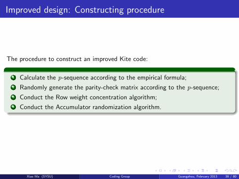
The procedure to construct an improved Kite code:
1 Calculate the p-sequence according to the empirical formula;
2 Randomly generate the parity-check matrix according to the p-sequence;
3 Conduct the Row weight concentration algorithm;
4 Conduct the Accumulator randomization algorithm.
Xiao Ma (SYSU) Coding Group Guangzhou, February 2013 39 / 80

Improved design: Numerical result
A Kite code with data length k = 9450. The average decoding rates (at“zero”error probability) of this improved Kite code over AWGN channels is shown below.
−10 −5 0 5 100
0.1
0.2
0.3
0.4
0.5
0.6
0.7
0.8
0.9
1
SNR (signal−to−Noise−Ratio) = 10log10
(1/σ2) [dB]
Rat
e [b
its/B
PS
K]
CapacityImproved Kite code k=9450RS− Kite code k=50000
Xiao Ma (SYSU) Coding Group Guangzhou, February 2013 40 / 80

Rate-compatible codes and adaptive coded modulation
The system model for adaptive coded modulation is shown below.
SourceModified
Kite Encoder
Modulator
(Gray Mapper)
AWGN
channel
SinkModified
Kite DecoderDemodulator(Bit Metric Calculator)
^
x
y
][nc
][nc
Xiao Ma (SYSU) Coding Group Guangzhou, February 2013 41 / 80

Rate-compatible codes and adaptive coded modulation
The average decoding spectral efficiency (at“zero”error probability) of theimproved Kite code with data length k = 9450 over AWGN channels.
−10 −5 0 5 10 15 20 25 30 350
1
2
3
4
5
6
7
8
9
SNR [dB]
Cap
acity
(bi
ts/s
ymbo
l)
Capacity
Simulation results
C = log(1+SNR)
1.53dB
QPSK
8PSK
16QAM
32QAM
64QAM
128QAM
256QAM
Xiao Ma (SYSU) Coding Group Guangzhou, February 2013 42 / 80

Summary
Given
any code length k ,
any code rate r ,
we construct a well-performed binary LDPC code.
Application1 Broadcasting common information;
2 Adaptive coded modulation;
3 Easily extended to group code[MA11b];
4 Joint source-channel code[YANG12];
5 Useful for research.
[MA11a]X. Ma et al, “Kite codes over groups”, ITW 2011[YANG12]Z. Yang, S. Zhao, X. Ma and B. Bai“A new joint source-channel codingscheme based on nested lattice codes”, IEEE Communication Letters 2012
Xiao Ma (SYSU) Coding Group Guangzhou, February 2013 43 / 80

Pair of rates: (0.48, 0.88).
Xiao Ma (SYSU) Coding Group Guangzhou, February 2013 44 / 80

A rateless transmission scheme for two-user Gaussian broadcast channels.
IJKLMNO LP Q
RQSSTKNUVTSN WLMN
X
X Y ZQSSTKN [LTJS \N]^NJKN _ Y KLMNM ZQSSTKN [LTJS \N]^NJKN
`TaJQZ [LTJS
\NZNKSLO
bcdefg hcicjk kcidel kmnomdpm
q r st u vw
Figure: Encoding structure of the two-way lattice-Kite code.
Figure: Gaussian broadcast channel.
two receivers, R1 and R2 withsinal-to-noise ratios (SNR) SNR1
and SNR2, respectively;
we assume that∆SNR = SNR1 − SNR2 > 0.That is , receiver R1 sees a betterchannel.
Xiao Ma (SYSU) Coding Group Guangzhou, February 2013 45 / 80

x xyz z zyz { {yz | |yz } }yz ~�y}
�
�y�
�yx
�y{
�y}
�
���������
������
������������������������ ��¡��¢����¡��£
¤¥¦§¨© ª«
¤¥¦§¨� ª«
¤¥¦§¨� ª«
¤¥¦§¨� ª«
Figure: Bandwidth efficiency of the proposed rateless transmission scheme for TU-GBC.
Xiao Ma (SYSU) Coding Group Guangzhou, February 2013 46 / 80

Outline
1 Single- and Multi-User Communication
2 Superposition Coded Modulation
3 Kite Codes
4 Block Markov Superposition Transmission
5 Conclusions
Xiao Ma (SYSU) Coding Group Guangzhou, February 2013 47 / 80

Block Markov Superposition Transmission
Gaussian Relay Channel
A sender X and an ultimate intended receiver Y;
The Gaussian relay channel is given by
Y1 = X + Z1
Y = X + Z1 +X1 + Z2,
where Z1 and Z2 are independent zero-mean Gaussian random variables withvariance N1 and N2, respectively;
The encoding allowed by the relay is the causal sequence
X1i = fi (Y11,Y12, . . . ,Y1i−1);
Sender X has power P and sender X1 has power P1.
Xiao Ma (SYSU) Coding Group Guangzhou, February 2013 48 / 80

Block Markov Superposition Transmission
Capacity of the Gaussian Relay Channel
The capacity is
C = max0≤α≤1
min{
C (P + P1 + 2
√αPP1
N1 +N2
),C (αP
N1
)}
,
where α = 1 − α.
Basic Techniques for the Proof of Achievability
Random coding;
List codes;
Slepian-Wolf partitioning;
Coding for the cooperative multiple-access channel;
Superposition coding;
Block Markov encoding at the relay and transmitter.
Xiao Ma (SYSU) Coding Group Guangzhou, February 2013 49 / 80

Block Markov Superposition Transmission
Superposition Block Markov Encoding (SBME) in the Relay Channel
The data are equally grouped into B blocks;
Initially, the source broadcasts a codeword that corresponds to the first datablock;
Then the source and the relay cooperatively transmit more information aboutthe first data block;
In the meanwhile, the source“superimposes”a codeword that corresponds tothe second data block;
Finally, the destination recovers the first data block from the two successivereceived blocks;
After removing the effect of the first data block, the system returns to theinitial state;
This process iterates B + 1 times until all B blocks of data are sentsuccessfully.
We apply a similar strategy (SBME) to the single-user communication system,resulting in the block Markov superposition transmission (BMST) scheme.
Xiao Ma (SYSU) Coding Group Guangzhou, February 2013 50 / 80

Block Markov Superposition Transmission
BMST schemeThe data are equally grouped into B blocks;
Initially, the transmitter sends a codeword that corresponds to the first datablock;
Since the short code is weak, the receiver is unable to recover reliably thedata from the current received block. Hence the transmitter transmits thecodeword (in its interleaved version) one more time.
In the meanwhile, a fresh codeword that corresponds to the second datablock is superimposed on the second block transmission.
Finally, the receiver recovers the first data block from the two successivereceived blocks.
After removing the effect of the first data block, the system returns to theinitial state;
This process iterates B + 1 times until all B blocks of data are sentsuccessfully.
[MA13]X. Ma et al, “Obtaining extra coding gain for short codes by block Markovsuperposition transmission”, submitted to ISIT, 2013
Xiao Ma (SYSU) Coding Group Guangzhou, February 2013 51 / 80
Block Markov Superposition Transmission
Encoding
C D D D
+
…
+
m-1
+
m
+
…
…
u(t)
v(t)
v(t-1)
v(t-2)
v(t-m+1)
v(t-m)
c(t)
w(1)
w(2)
w(m-1)
w(m)
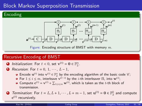
Figure: Encoding structure of BMST with memory m.
Recursive Encoding of BMST
1 Initialization: For t < 0, set v(t)= 0 ∈ Fn
2.
2 Recursion: For t = 0, 1, · · · , L − 1,Encode u
(t ) into v(t ) ∈ Fn
2by the encoding algorithm of the basic code C ;
For 1 ≤ i ≤ m, interleave v(t−i) by the i-th interleaver Πi into w
(i);Compute c
(t )= v
(t )+
∑
1≤i≤m w(i), which is taken as the t-th block of
transmission.
3 Termination: For t = L,L + 1, · · · ,L +m − 1, set u(t)= 0 ∈ Fk
2and compute
c(t) recursively.
Xiao Ma (SYSU) Coding Group Guangzhou, February 2013 52 / 80

Block Markov Superposition Transmission
Normal Graph
1 2
=
C
C(0)
U(0)
V(0)
1 2
=
C
+
C(3)
U(3)
V(3)
1 2
=
C
+
C(2)
U(2)
V(2)
+
C(4)
C(5)
1 2
=
C
+
C(1)
U(1)
V(1)
a decoding layer
Figure: The normal graph of a code with L = 4 and m = 2.
Decoding
an iterative sliding-window decoding algorithm is used;
four types of nodes: C , =, +, and∏
;
messages are processed and passed through different decoding layers forwardand backward over the normal graph;
Xiao Ma (SYSU) Coding Group Guangzhou, February 2013 53 / 80

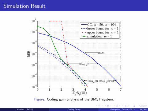
Coding Gain Analysis of the BMST
Genie-Aided Lower Bound on BERThe performance of the BMST under MAP decoding is determined by
Pr{u (t)j|y} =
∑
u′
Pr{u′|y}Pr{u (t)j|u′,y},
where the summation is over u′ = {u(i), t −m ≤ i ≤ t +m, i , t };
the BER performance can be lower-bounded by
fn (γb) ≥ fo(γb + 10 log10(m + 1) − 10 log10(1 +m/L));
noticing that Pr{u′|y} ≈ 1 for the transmitted data block u′ in the low errorrate region, we can expect that
fn (γb) ≈ fo(γb + 10 log10(m + 1) − 10 log10(1 +m/L))
as γb increases.
the maximum coding gain can be 10 log10(m + 1) dB for large L in the lowerror rate region.
Xiao Ma (SYSU) Coding Group Guangzhou, February 2013 54 / 80

Simulation Result
0 1 2 3 4 5 6 710
−6
10−5
10−4
10−3
10−2
10−1
100
BCJR
Eb/N
0(dB)
BE
RCC, k = 50, n = 104
Figure: Coding gain analysis of the BMST system.
Xiao Ma (SYSU) Coding Group Guangzhou, February 2013 55 / 80

Simulation Result
0 1 2 3 4 5 6 710
−6
10−5
10−4
10−3
10−2
10−1
100
BCJR
10log10
(2)
Eb/N
0(dB)
BE
RCC, k = 50, n = 104lower bound for m = 1
Figure: Coding gain analysis of the BMST system.
Xiao Ma (SYSU) Coding Group Guangzhou, February 2013 56 / 80

Simulation Result
0 1 2 3 4 5 6 710
−6
10−5
10−4
10−3
10−2
10−1
100
BCJR
10log10
(2)
10log10
(2)−10log10
(20/19)
Eb/N
0(dB)
BE
RCC, k = 50, n = 104lower bound for m = 1
Figure: Coding gain analysis of the BMST system.
Xiao Ma (SYSU) Coding Group Guangzhou, February 2013 57 / 80

Simulation Result
0 1 2 3 4 5 6 710
−6
10−5
10−4
10−3
10−2
10−1
100
BCJR
10log10
(2)
10log10
(2)−10log10
(20/19)
Eb/N
0(dB)
BE
RCC, k = 50, n = 104lower bound for m = 1upper bound for m = 1
Figure: Coding gain analysis of the BMST system.
Xiao Ma (SYSU) Coding Group Guangzhou, February 2013 58 / 80
Simulation Result
0 1 2 3 4 5 6 710
−6
10−5
10−4
10−3
10−2
10−1
100
BCJR
10log10
(2)
10log10
(2)−10log10
(20/19)
Eb/N
0(dB)
BE
RCC, k = 50, n = 104lower bound for m = 1upper bound for m = 1simulation, m = 1
Figure: Coding gain analysis of the BMST system.
Xiao Ma (SYSU) Coding Group Guangzhou, February 2013 59 / 80

Simulation Result
0 1 2 3 4 5 6 710
−7
10−6
10−5
10−4
10−3
10−2
10−1
100
BCJR only
CRC + list Viterbi
Eb/N
0(dB)
BE
R
Shannon limit of rate 1/2CRC + CC, k = 10000, n = 20068
Figure: The basic code C is a concatenated code of dimension k = 10000 and lengthn = 20068, where the outer code is a 32-bit CRC code and the inner code is aterminated 4-state (2, 1, 2) convolutional code.
Xiao Ma (SYSU) Coding Group Guangzhou, February 2013 60 / 80

Simulation Result
0 1 2 3 4 5 6 710
−7
10−6
10−5
10−4
10−3
10−2
10−1
100
BCJR only
CRC + list Viterbi10log10
(2)
Eb/N
0(dB)
BE
R
Shannon limit of rate 1/2CRC + CC, k = 10000, n = 20068
Figure: The basic code C is a concatenated code of dimension k = 10000 and lengthn = 20068, where the outer code is a 32-bit CRC code and the inner code is aterminated 4-state (2, 1, 2) convolutional code.
Xiao Ma (SYSU) Coding Group Guangzhou, February 2013 61 / 80

Simulation Result
0 1 2 3 4 5 6 710
−7
10−6
10−5
10−4
10−3
10−2
10−1
100
BCJR only
CRC + list Viterbi10log10
(2)
Eb/N
0(dB)
BE
R
Shannon limit of rate 1/2CRC + CC, k = 10000, n = 20068 m = 1, d = 7
Figure: The basic code C is a concatenated code of dimension k = 10000 and lengthn = 20068, where the outer code is a 32-bit CRC code and the inner code is aterminated 4-state (2, 1, 2) convolutional code.
Xiao Ma (SYSU) Coding Group Guangzhou, February 2013 62 / 80

Simulation Result
0 1 2 3 4 5 6 710
−7
10−6
10−5
10−4
10−3
10−2
10−1
100
BCJR only
CRC + list Viterbi10log10
(2)
10log10
(3)
Eb/N
0(dB)
BE
R
Shannon limit of rate 1/2CRC + CC, k = 10000, n = 20068 m = 1, d = 7
Figure: The basic code C is a concatenated code of dimension k = 10000 and lengthn = 20068, where the outer code is a 32-bit CRC code and the inner code is aterminated 4-state (2, 1, 2) convolutional code.
Xiao Ma (SYSU) Coding Group Guangzhou, February 2013 63 / 80

Simulation Result
0 1 2 3 4 5 6 710
−7
10−6
10−5
10−4
10−3
10−2
10−1
100
BCJR only
CRC + list Viterbi10log10
(2)
10log10
(3)
Eb/N
0(dB)
BE
R
Shannon limit of rate 1/2CRC + CC, k = 10000, n = 20068 m = 1, d = 7 m = 2, d = 2 m = 2, d = 7 m = 2, d = 7 with list Viterbi
Figure: The basic code C is a concatenated code of dimension k = 10000 and lengthn = 20068, where the outer code is a 32-bit CRC code and the inner code is aterminated 4-state (2, 1, 2) convolutional code.
Xiao Ma (SYSU) Coding Group Guangzhou, February 2013 64 / 80

Simulation Result
0 1 2 3 4 5 6 710
−7
10−6
10−5
10−4
10−3
10−2
10−1
100
BCJR only
CRC + list Viterbi10log10
(2)
10log10
(3)
10log10
(4)
Eb/N
0(dB)
BE
R
Shannon limit of rate 1/2CRC + CC, k = 10000, n = 20068 m = 1, d = 7 m = 2, d = 2 m = 2, d = 7 m = 2, d = 7 with list Viterbi
Figure: The basic code C is a concatenated code of dimension k = 10000 and lengthn = 20068, where the outer code is a 32-bit CRC code and the inner code is aterminated 4-state (2, 1, 2) convolutional code.
Xiao Ma (SYSU) Coding Group Guangzhou, February 2013 65 / 80

Simulation Result
0 1 2 3 4 5 6 710
−7
10−6
10−5
10−4
10−3
10−2
10−1
100
BCJR only
CRC + list Viterbi10log10
(2)
10log10
(3)
10log10
(4)
Eb/N
0(dB)
BE
R
Shannon limit of rate 1/2CRC + CC, k = 10000, n = 20068 m = 1, d = 7 m = 2, d = 2 m = 2, d = 7 m = 2, d = 7 with list Viterbi m = 3, d = 7
Figure: The basic code C is a concatenated code of dimension k = 10000 and lengthn = 20068, where the outer code is a 32-bit CRC code and the inner code is aterminated 4-state (2, 1, 2) convolutional code.
Xiao Ma (SYSU) Coding Group Guangzhou, February 2013 66 / 80
Simulation Result
0 1 2 3 4 5 6 7 810
−6
10−5
10−4
10−3
10−2
10−1
100
CRC + list Viterbi
BCJR only
Eb/N
0(dB)
BE
R
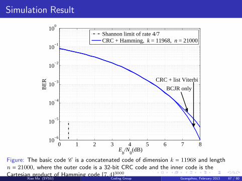
Shannon limit of rate 4/7CRC + Hamming, k = 11968, n = 21000
Figure: The basic code C is a concatenated code of dimension k = 11968 and lengthn = 21000, where the outer code is a 32-bit CRC code and the inner code is theCartesian product of Hamming code [7, 4]3000.
Xiao Ma (SYSU) Coding Group Guangzhou, February 2013 67 / 80

Simulation Result
0 1 2 3 4 5 6 7 810
−6
10−5
10−4
10−3
10−2
10−1
100
CRC + list Viterbi
BCJR only
10log10
(2)
Eb/N
0(dB)
BE
R
Shannon limit of rate 4/7CRC + Hamming, k = 11968, n = 21000
Figure: The basic code C is a concatenated code of dimension k = 11968 and lengthn = 21000, where the outer code is a 32-bit CRC code and the inner code is theCartesian product of Hamming code [7, 4]3000.
Xiao Ma (SYSU) Coding Group Guangzhou, February 2013 68 / 80

Simulation Result
0 1 2 3 4 5 6 7 810
−6
10−5
10−4
10−3
10−2
10−1
100
CRC + list Viterbi
BCJR only
10log10
(2)
Eb/N
0(dB)
BE
R
Shannon limit of rate 4/7CRC + Hamming, k = 11968, n = 21000 m = 1, d = 7
Figure: The basic code C is a concatenated code of dimension k = 11968 and lengthn = 21000, where the outer code is a 32-bit CRC code and the inner code is theCartesian product of Hamming code [7, 4]3000.
Xiao Ma (SYSU) Coding Group Guangzhou, February 2013 69 / 80

Simulation Result
0 1 2 3 4 5 6 7 810
−6
10−5
10−4
10−3
10−2
10−1
100
CRC + list Viterbi
BCJR only
10log10
(2)
10log10
(3)
Eb/N
0(dB)
BE
R
Shannon limit of rate 4/7CRC + Hamming, k = 11968, n = 21000 m = 1, d = 7
Figure: The basic code C is a concatenated code of dimension k = 11968 and lengthn = 21000, where the outer code is a 32-bit CRC code and the inner code is theCartesian product of Hamming code [7, 4]3000.
Xiao Ma (SYSU) Coding Group Guangzhou, February 2013 70 / 80

Simulation Result
0 1 2 3 4 5 6 7 810
−6
10−5
10−4
10−3
10−2
10−1
100
CRC + list Viterbi
BCJR only
10log10
(2)
10log10
(3)
Eb/N
0(dB)
BE
R
Shannon limit of rate 4/7CRC + Hamming, k = 11968, n = 21000 m = 1, d = 7 m = 2, d = 7 m = 2, d = 7 with list Viterbi
Figure: The basic code C is a concatenated code of dimension k = 11968 and lengthn = 21000, where the outer code is a 32-bit CRC code and the inner code is theCartesian product of Hamming code [7, 4]3000.
Xiao Ma (SYSU) Coding Group Guangzhou, February 2013 71 / 80

Simulation Result
0 1 2 3 4 5 6 7 810
−6
10−5
10−4
10−3
10−2
10−1
100
CRC + list Viterbi
BCJR only
10log10
(2)
10log10
(3)
10log10
(4)
Eb/N
0(dB)
BE
R
Shannon limit of rate 4/7CRC + Hamming, k = 11968, n = 21000 m = 1, d = 7 m = 2, d = 7 m = 2, d = 7 with list Viterbi
Figure: The basic code C is a concatenated code of dimension k = 11968 and lengthn = 21000, where the outer code is a 32-bit CRC code and the inner code is theCartesian product of Hamming code [7, 4]3000.
Xiao Ma (SYSU) Coding Group Guangzhou, February 2013 72 / 80

Simulation Result
0 1 2 3 4 5 6 7 810
−6
10−5
10−4
10−3
10−2
10−1
100
CRC + list Viterbi
BCJR only
10log10
(2)
10log10
(3)
10log10
(4)
Eb/N
0(dB)
BE
R
Shannon limit of rate 4/7CRC + Hamming, k = 11968, n = 21000 m = 1, d = 7 m = 2, d = 7 m = 2, d = 7 with list Viterbi m = 3, d = 7
Figure: The basic code C is a concatenated code of dimension k = 11968 and lengthn = 21000, where the outer code is a 32-bit CRC code and the inner code is theCartesian product of Hamming code [7, 4]3000.
Xiao Ma (SYSU) Coding Group Guangzhou, February 2013 73 / 80

Simulation Result
0 1 2 3 4 5 6 7 810
−6
10−5
10−4
10−3
10−2
10−1
100
CRC + list Viterbi
BCJR only
10log10
(2)
10log10
(3)
10log10
(4)
10log10
(5)
Eb/N
0(dB)
BE
R
Shannon limit of rate 4/7CRC + Hamming, k = 11968, n = 21000 m = 1, d = 7 m = 2, d = 7 m = 2, d = 7 with list Viterbi m = 3, d = 7
Figure: The basic code C is a concatenated code of dimension k = 11968 and lengthn = 21000, where the outer code is a 32-bit CRC code and the inner code is theCartesian product of Hamming code [7, 4]3000.
Xiao Ma (SYSU) Coding Group Guangzhou, February 2013 74 / 80

Simulation Result
0 1 2 3 4 5 6 7 810
−6
10−5
10−4
10−3
10−2
10−1
100
CRC + list Viterbi
BCJR only
10log10
(2)
10log10
(3)
10log10
(4)
10log10
(5)
Eb/N
0(dB)
BE
R
Shannon limit of rate 4/7CRC + Hamming, k = 11968, n = 21000 m = 1, d = 7 m = 2, d = 7 m = 2, d = 7 with list Viterbi m = 3, d = 7 m = 4, d = 7
Figure: The basic code C is a concatenated code of dimension k = 11968 and lengthn = 21000, where the outer code is a 32-bit CRC code and the inner code is theCartesian product of Hamming code [7, 4]3000.
Xiao Ma (SYSU) Coding Group Guangzhou, February 2013 75 / 80

Simulation Result
Performance of the BMST System
1 1.5 2 2.5 310
−6
10−5
10−4
10−3
10−2
10−1
100
BM + BCJR
Eb/N
0(dB)
BE
R
RS + CC, k = 1784, n = 4092
Figure: The basic code C is the Consultative Committee on Space Data System(CCSDS) standard code of dimension k = 1784 and length n = 4092, where the outercode is a [255, 223] Reed-Solomon (RS) code over F256 and the inner code is aterminated 64-state (2, 1, 6) convolutional code.
Xiao Ma (SYSU) Coding Group Guangzhou, February 2013 76 / 80
Simulation Result
Performance of the BMST System
1 1.5 2 2.5 310
−6
10−5
10−4
10−3
10−2
10−1
100
BM + BCJR
Eb/N
0(dB)
BE
R
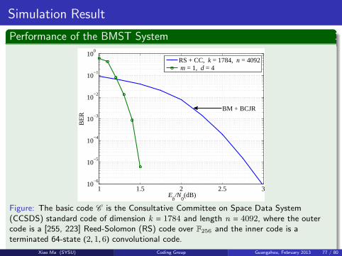
RS + CC, k = 1784, n = 4092 m = 1, d = 4
Figure: The basic code C is the Consultative Committee on Space Data System(CCSDS) standard code of dimension k = 1784 and length n = 4092, where the outercode is a [255, 223] Reed-Solomon (RS) code over F256 and the inner code is aterminated 64-state (2, 1, 6) convolutional code.
Xiao Ma (SYSU) Coding Group Guangzhou, February 2013 77 / 80

Outline
1 Single- and Multi-User Communication
2 Superposition Coded Modulation
3 Kite Codes
4 Block Markov Superposition Transmission
5 Conclusions
Xiao Ma (SYSU) Coding Group Guangzhou, February 2013 78 / 80

Conclusions
Superposition Coded Modulation
We proposed a coded modulation system using superimposed binary codes;
Using the unequal power-allocations and the Gaussian-approximation-basedsuboptimal demapping algorithm, coded modulation with high bandwidthefficiency can be implemented.
Kite CodesWe proposed a kind of rateless codes for AWGN channels;
A greedy optimization was presented to optimize Kite codes;
Three methods were presented either to improve the performance of Kitecodes, or to accelerate the design of Kite codes;
Possible applications of Kite codes were investigated.
Block Markov Superposition Transmission
We presented a new method for constructing long codes from short codes;
The encoding process can be as fast as the short code, while the decodinghas a fixed delay.
Xiao Ma (SYSU) Coding Group Guangzhou, February 2013 79 / 80
Acknowledgements
Thank You for Your Attention!
Xiao Ma (SYSU) Coding Group Guangzhou, February 2013 80 / 80