single step joint : overview of european standardized
TRANSCRIPT

XII Congresso Internacional sobre Patologia e Reabilitação de Estruturas XII International Conference on Structural Repair and Rehabilitation
26-29 October, 2016, Porto, Portugal
1
Single Step Joint : overview of European standardized approaches and experimentations
Maxime VERBIST1, Jorge BRANCO2, Elisa POLETTI3, Thierry DESCAMPS4, Paulo LOURENCO5
1 University of Mons, Rue du Joncquois 53, 7000, Mons, Belgium, [email protected]
2 University of Minho, Campus de Azurém, 4800-058, Guimarães, Portugal, [email protected] 3 University of Minho, Campus de Azurém, 4800-058, Guimarães, Portugal, [email protected]
4 University of Mons, Rue du Joncquois 53, 7000, Mons, Belgium, [email protected]
5 University of Minho, Campus de Azurém, 4800-058, Guimarães, Portugal, [email protected]
Abstract: In the field of the built heritage restoration, engineers have to work with old structures made of badly preserved timber elements. The assessment of timber elements and connections is a major issue for engineers involved in a restoration project. Before thinking about any intervention technics, engineers have to properly understand how the carpentry connections fail, which parameters influence the failure modes (geometry of the joint, mechanical properties of the wood,…) and how the internal forces are distributed into the joint to finally figure out how to design the traditional carpentry connections. The present paper aims to raise those questions focusing on the Single Step Joint design. Even if this common joint between the rafter and the tie beam is geometrically simple, one may pick up three geometrical configurations of Simple Notched Joints from the past till today: the geometrical configuration ideal (GCID), the geometrical configuration perpendicular to the tie beam (GCPTB) and the geometrical configuration perpendicular to the rafter (GCPR). The first one is more recent because it requires a highest accuracy production, and so the use of the new technologies (e.g., CNC). For each one, some general design rules about the geometrical parameters of the Single Step Joint are defined by some European standards (Siem and Jorissen, 2015), but no one details how to design this connection to prevent shear cracks at the heel depth or the compressive crushing at the joint contact surfaces. Hence the design rules and the emergence of failure modes according to the geometrical parameters of the Simple Notched Joint must be defined. In order to check the design equations and the failure modes, lab tests about the three geometrical configurations of the Single Step Joint have been carried out, varying the heel depth, the shear length and the inclination of the rafter.
Keywords: Timber – Traditional carpentry connections – Single Step Joint – Design – Experimentation
1. Introduction
From the old carpentries (e.g. Roman, King-post, …) to the contemporary trusses, the Notched Joints have been always used in order to connect the rafter with the tie beam or sometimes the king-post, as show in the Figure 1. This traditional carpentry connection includes several geometrical variants over time. However, the Single Step Joint stays the most common because its simple configuration makes easier the timber cutting by the carpenters. Moreover, different geometrical configurations from this connection can be gathered into three families : the GCID, GCPR and GCPTB. Although the first one is recent due to the apparition of the new timber cutting technologies (e.g., CNC), the both others families are always encountered in the old traditional carpentries because the former carpenters didn’t have any high precision tools so as to design the Geometrical Configuration Ideal of the joint accurately.
The understanding of failure modes, their emergence and the design equations regarding the Simple Notched Joint must be considered before thinking about any intervention technics in the field of the built heritage restoration. Therefore, the paper focuses on two investigation steps concerning the three Single Step Joint families. The first one called ‘’Theoretical campaign’’ aims to determine the design equations according to the geometrical parameters of the connection, basing on some theories and

XII Congresso Internacional sobre Patologia e Reabilitação de Estruturas XII International Conference on Structural Repair and Rehabilitation
26-29 October, 2016, Porto, Portugal
Single Step Joint : overview of European standardized approaches and experimentations 2
recommendations from the European standards. In order to check the design equations and the emergence of the failure modes, several specimens of the Simple Notched Joint must be carried out by monotonic compression tests in the Experimental Campaign, varying the geometrical parameters defined in the previous step.
Figure 1 – Timber elements constituting the traditional carpentry (King-post truss).
2. Theoretical campaign of the Single Step Joint
This campaign mainly aims to define the design equations of the Single Step Joint according to the shear failure and the compressive crushing. As the connection geometry influences these both failure modes and their emergences, the geometrical parameters of the Simple Notched Joint must be defined. All the geometrical configurations can be gathered into three families (e.g. GCID , GCPR and GCPTB).
Moreover, the internal resolution of forces must be defined between the rafter and the tie beam by different methods, as the Simplified Resolution of forces (SRF) and the Triangle Resolution of Forces (TRF). If the intensity and the repartition of these forces are known at the contact surfaces of the Single Step Joint, the emergence of any failure mode can be predicted.
In addition to this, it’s necessary to develop a theory about the Hammock Shape Shear Stress Distribution (HSSSD) in order to explain further the emergence of the shear failure. This concept of non-uniform shear stress concentrated at the heel depth of the tie beam is fundamental to explain the phenomenon’s related to the shear crack noticed during the experimental campaign. Also, some geometrical restrictions of this traditional connection are provided by European standards to prevent the consequences of the HSSSD, such as the decrease of the shear strength in the Simple Notched Joint.
2.1 Geometrical Configurations
As common connections in the traditional carpentry, the Single Step Joint however counts a variety of geometrical configurations according to their general geometrical parameters and their membership to the three families of the Simple Notched Joint : GCID, GCPR and GCPTB.
2.1.1 – General geometrical parameters
Whatever the different geometrical configurations, the Single Step Joint includes two contact surfaces between the rafter and the tie beam, as shown in the Figure 2. The first one called ‘’front-notch surface’’ is

XII Congresso Internacional sobre Patologia e Reabilitação de Estruturas XII International Conference on Structural Repair and Rehabilitation
26-29 October, 2016, Porto, Portugal
Single Step Joint : overview of European standardized approaches and experimentations 3
located in the front of the Simple Notched joint. It aims to counteract the rafter thrust, like horizontal support. More the rafter skew angle 𝛽 is low, more the front-notch surface is subjected to high internal forces. Because of the small contact area and the highest horizontal component of rafter forces, the carpentry connection may fail at the front-notch surface either by crushing of the timber under an angle 𝛼 to the grain, or by shear crack at the heel depth of the tie beam. Moreover, the front-notch surface is characterized by an inclination angle 𝛼 relative to the vertical direction. More the parameter α rises according to the rafter skew angle 𝛽, more the characteristic compressive strength 𝑓𝑐,𝛼,𝑘 decreases because of the timber orthotropic mechanical behaviour. For geometrical configurations including any similar rafter skew angle 𝛽, the compressive crushing emergence in the rafter or tie beam side is determined by the highest angle α between the front-notch surface and the grain directions of the rafter and the tie beam. Hence the compressive crushing at the front-notch surface may occur for geometrical configurations with a low rafter skew angle 𝛽.
The second contact surface called ‘’bottom-notch’’ is localized in the rear of the Single Step Joint. It bears the vertical component of the rafter force, like vertical support. More the rafter skew angle 𝛽 rises, more the contact surface is subjected to high internal forces. In contrast to the front-notch one, the bottom-notch surface has a widest area in order to spread the vertical compressive stress so that this contact area is little solicited. By the way, the inclination angle of the bottom-notch surface to the grain in the tie beam can be defined, noted 𝛾 as shown in the Figure 2. Whatever the rafter skew angle 𝛽, this angle 𝛾 is always very small. Hence, the characteristic compressive strength under the angle ‘’90° − 𝛾’’ to the grain noted 𝑓𝑐,90°−𝛾,𝑘 is closer to 𝑓𝑐,90°,𝑘. As the bottom-notch contact surface is almost parallel to the grain in the tie
beam, the related characteristic compressive strength 𝑓𝑐,90°−𝛾,𝑘 is lower that the front-notch surface one
𝑓𝑐,𝛼,𝑘. Therefore the compressive crushing at the bottom-notch surface may emerge for geometrical configurations including highest rafter skew angles 𝛽.
Figure 2 – General geometrical parameters of the Single Step Joint.
Some geometrical parameters of the Simple Notched Joint, as the shear length 𝑙𝑣 lv and the heel depth 𝑡𝑣, determine the emergence conditions of the shear crack. This failure mode occurs at the heel depth of the front-notch surface and spreads along the grain in the tie beam. Coming from the rafter thrust, the shear stress strongly rises for small rafter inclination angles 𝛽. Moreover, the low characteristic shear strength 𝑓𝑣,𝑘 parallel to the grain doesn’t grant any sufficient resistance against the shear crack in this traditional timber connection. Despite this, the shear strength of the Single Step Joint can be improved by the increase of both geometrical parameters 𝑙𝑣 and 𝑡𝑣. However, the maximal shear length is often limited by some architectural restrictions concerning the roof support at the top of walls where the Simple Notched Joint is located. As used in the timber truss in order to decrease the rainwater flow, the coyau however allows to break free of this constraint. Moreover, the maximal heel depth 𝑡𝑣 is restricted to avoid the emergence of any tension or shear failures in the cross-section of the tie beam. According to Siem and Jorissen (2015), the German norm DIN 1052 sets the maximal values of the heel depth related to the rafter skew angle 𝛽 in the Table 1. Concerning the parameter 𝑙𝑣 , the same standard imposes 𝑙𝑣,𝑚𝑖𝑛 = 200 𝑚𝑚
XII Congresso Internacional sobre Patologia e Reabilitação de Estruturas XII International Conference on Structural Repair and Rehabilitation
26-29 October, 2016, Porto, Portugal
Single Step Joint : overview of European standardized approaches and experimentations 4
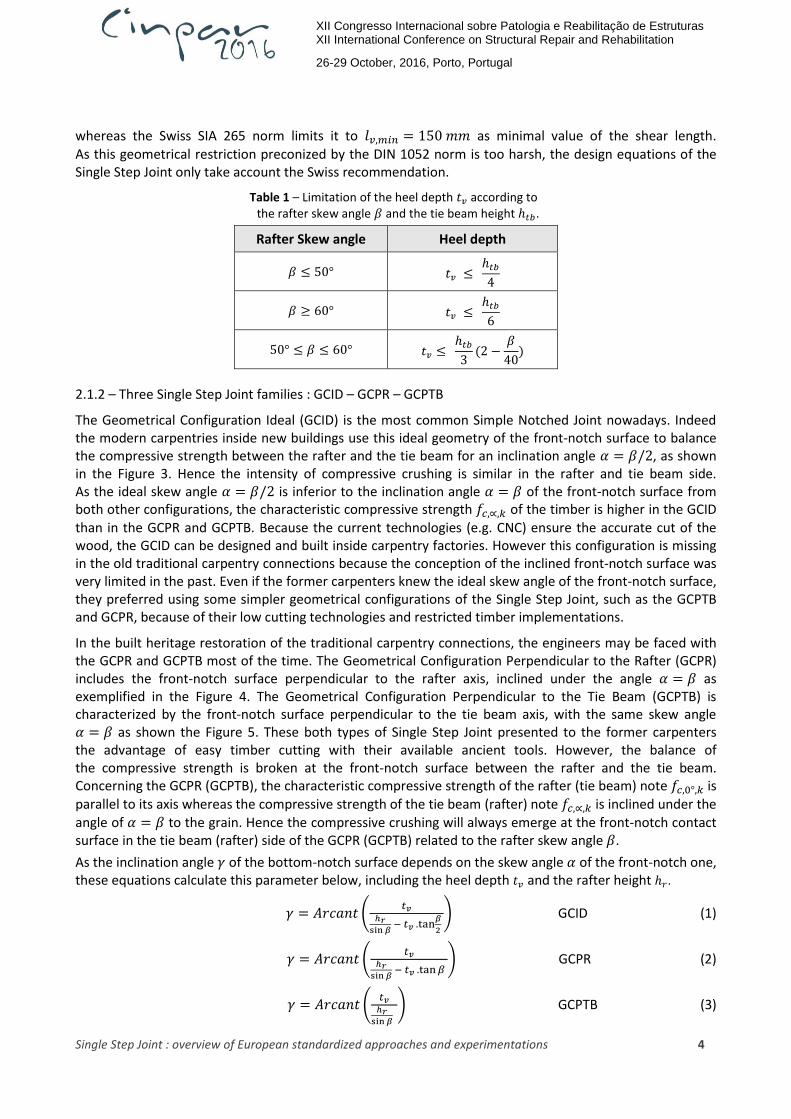
whereas the Swiss SIA 265 norm limits it to 𝑙𝑣,𝑚𝑖𝑛 = 150 𝑚𝑚 as minimal value of the shear length. As this geometrical restriction preconized by the DIN 1052 norm is too harsh, the design equations of the Single Step Joint only take account the Swiss recommendation.
Table 1 – Limitation of the heel depth 𝑡𝑣 according to the rafter skew angle 𝛽 and the tie beam height ℎ𝑡𝑏.
Rafter Skew angle Heel depth
𝛽 ≤ 50° 𝑡𝑣 ≤ ℎ𝑡𝑏
4
𝛽 ≥ 60° 𝑡𝑣 ≤ ℎ𝑡𝑏
6
50° ≤ 𝛽 ≤ 60° 𝑡𝑣 ≤ ℎ𝑡𝑏
3(2 −
𝛽
40)
2.1.2 – Three Single Step Joint families : GCID – GCPR – GCPTB
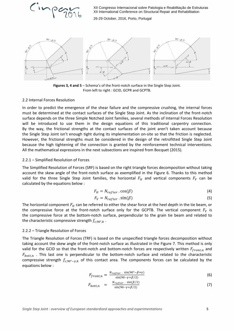
The Geometrical Configuration Ideal (GCID) is the most common Simple Notched Joint nowadays. Indeed the modern carpentries inside new buildings use this ideal geometry of the front-notch surface to balance the compressive strength between the rafter and the tie beam for an inclination angle 𝛼 = 𝛽/2, as shown in the Figure 3. Hence the intensity of compressive crushing is similar in the rafter and tie beam side. As the ideal skew angle 𝛼 = 𝛽/2 is inferior to the inclination angle 𝛼 = 𝛽 of the front-notch surface from both other configurations, the characteristic compressive strength 𝑓𝑐,∝,𝑘 of the timber is higher in the GCID than in the GCPR and GCPTB. Because the current technologies (e.g. CNC) ensure the accurate cut of the wood, the GCID can be designed and built inside carpentry factories. However this configuration is missing in the old traditional carpentry connections because the conception of the inclined front-notch surface was very limited in the past. Even if the former carpenters knew the ideal skew angle of the front-notch surface, they preferred using some simpler geometrical configurations of the Single Step Joint, such as the GCPTB and GCPR, because of their low cutting technologies and restricted timber implementations.
In the built heritage restoration of the traditional carpentry connections, the engineers may be faced with the GCPR and GCPTB most of the time. The Geometrical Configuration Perpendicular to the Rafter (GCPR) includes the front-notch surface perpendicular to the rafter axis, inclined under the angle 𝛼 = 𝛽 as exemplified in the Figure 4. The Geometrical Configuration Perpendicular to the Tie Beam (GCPTB) is characterized by the front-notch surface perpendicular to the tie beam axis, with the same skew angle 𝛼 = 𝛽 as shown the Figure 5. These both types of Single Step Joint presented to the former carpenters the advantage of easy timber cutting with their available ancient tools. However, the balance of the compressive strength is broken at the front-notch surface between the rafter and the tie beam. Concerning the GCPR (GCPTB), the characteristic compressive strength of the rafter (tie beam) note 𝑓𝑐,0°,𝑘 is parallel to its axis whereas the compressive strength of the tie beam (rafter) note 𝑓𝑐,∝,𝑘 is inclined under the
angle of 𝛼 = 𝛽 to the grain. Hence the compressive crushing will always emerge at the front-notch contact surface in the tie beam (rafter) side of the GCPR (GCPTB) related to the rafter skew angle 𝛽.
As the inclination angle 𝛾 of the bottom-notch surface depends on the skew angle 𝛼 of the front-notch one, these equations calculate this parameter below, including the heel depth 𝑡𝑣 and the rafter height ℎ𝑟.
𝛾 = 𝐴𝑟𝑐𝑎𝑛𝑡 (𝑡𝑣
ℎ𝑟sin 𝛽
− 𝑡𝑣 .tan𝛽
2 ) GCID (1)
𝛾 = 𝐴𝑟𝑐𝑎𝑛𝑡 (𝑡𝑣
ℎ𝑟sin 𝛽
− 𝑡𝑣 .tan 𝛽 ) GCPR (2)
𝛾 = 𝐴𝑟𝑐𝑎𝑛𝑡 (𝑡𝑣
ℎ𝑟sin 𝛽
) GCPTB (3)
XII Congresso Internacional sobre Patologia e Reabilitação de Estruturas XII International Conference on Structural Repair and Rehabilitation
26-29 October, 2016, Porto, Portugal
Single Step Joint : overview of European standardized approaches and experimentations 5
Figures 3, 4 and 5 – Schema’s of the front-notch surface in the Single Step Joint. From left to right : GCID, GCPR and GCPTB.
2.2 Internal Forces Resolution
In order to predict the emergence of the shear failure and the compressive crushing, the internal forces must be determined at the contact surfaces of the Single Step Joint. As the inclination of the front-notch surface depends on the three Simple Notched Joint families, several methods of Internal Forces Resolution will be introduced to use them in the design equations of this traditional carpentry connection. By the way, the frictional strengths at the contact surfaces of the joint aren’t taken account because the Single Step Joint isn’t enough tight during its implementation on-site so that the friction is neglected. However, the frictional strengths must be considered in the design of the retrofitted Single Step Joint because the high tightening of the connection is granted by the reinforcement technical interventions. All the mathematical expressions in the next subsections are inspired from Bocquet (2015).
2.2.1 – Simplified Resolution of Forces
The Simplified Resolution of Forces (SRF) is based on the right triangle forces decomposition without taking account the skew angle of the front-notch surface as exemplified in the Figure 6. Thanks to this method valid for the three Single Step Joint families, the horizontal 𝐹𝐻 and vertical components 𝐹𝑉 can be calculated by the equations below :
𝐹𝐻 = 𝑁𝑟𝑎𝑓𝑡𝑒𝑟 . cos(𝛽) (4)
𝐹𝑉 = 𝑁𝑟𝑎𝑓𝑡𝑒𝑟 . sin(𝛽) (5)
The horizontal component 𝐹𝐻 can be referred to either the shear force at the heel depth in the tie beam, or the compressive force at the front-notch surface only for the GCPTB. The vertical component 𝐹𝑉 is the compressive force at the bottom-notch surface, perpendicular to the grain tie beam and related to the characteristic compressive strength 𝑓𝑐,90°,𝑘 .
2.2.2 – Triangle Resolution of Forces
The Triangle Resolution of Forces (TRF) is based on the unspecified triangle forces decomposition without taking account the skew angle of the front-notch surface as illustrated in the Figure 7. This method is only valid for the GCID so that the front-notch and bottom-notch forces are respectively written 𝐹𝑓𝑟𝑜𝑛𝑡,𝑛 and
𝐹𝑏𝑜𝑡𝑡,𝑛 . This last one is perpendicular to the bottom-notch surface and related to the characteristic compressive strength 𝑓𝑐,90°−𝛾,𝑘 of this contact area. The components forces can be calculated by the
equations below :
𝐹𝑓𝑟𝑜𝑛𝑡,𝑛 = 𝑁𝑟𝑎𝑓𝑡𝑒𝑟 . sin(90°−𝛽+𝛾)
sin(90−𝛾+𝛽 2⁄ ) (6)
𝐹𝑏𝑜𝑡𝑡,𝑛 = 𝑁𝑟𝑎𝑓𝑡𝑒𝑟 . sin(𝛽 2⁄ )
sin(90−𝛾+𝛽 2⁄ ) (7)

XII Congresso Internacional sobre Patologia e Reabilitação de Estruturas XII International Conference on Structural Repair and Rehabilitation
26-29 October, 2016, Porto, Portugal
Single Step Joint : overview of European standardized approaches and experimentations 6
Figures 6 and 7 – Schema’s of the forces decomposition : SRF (left) and TRF methods (right)
2.3 Hammock Shape Shear Stress Distribution
The Single Step Joint is featured by several geometrical configurations very different from the Classical connections whose the joint timber members are parallel each other. As the inclined rafter and the tie beam join in the Simple Notched Joint, the heterogeneous Shear Stress Distribution may be expected at the heel depth on the shear plane in the tie beam, as illustrated in the Figure 8. Therefore the theory of the Hammock Shape Shear Stress Distribution (HSSSD) must be revised and detailed in order to predict the experimental phenomenon’s encountered. According to Siem and Jorissen (2014), the German Annex from EC5 takes account the non-uniform shear stress distribution, involving the decrease of the characteristic shear strength 𝑓𝑣,𝑘 by a reducer coefficient : 𝑘𝑣,𝑟𝑒𝑑 = 0,8 . Regarding the same authors, the German Standard DIN 1052 (2004) imposes the geometrical restriction about the maximal shear length of the tie beam 𝑙𝑣,𝑚𝑎𝑥 , related to the heel depth 𝑡𝑣 such as 𝑙𝑣,𝑚𝑎𝑥 = 8. 𝑡𝑣 .
If the shear length 𝑙𝑣 is superior to 8. 𝑡𝑣 , the shear stress 𝜏𝐸𝑑 is insignificant and the timber shear strength badly works along the extra shear length, as shown the Figure 8. Hence the condition 𝑙𝑣 ≤ 8. 𝑡𝑣 must be checked in order to encompass the HSSSD whose the shear stress concentration peak is located at the heel depth of the front-notch surface. Concerning the design equations about the shear failure, the effective shear length 𝑙𝑣,𝑒𝑓𝑓 takes account the geometrical restriction from the DIN 1052 norm :
𝑙𝑣,𝑒𝑓𝑓 = min (𝑙𝑣 ; 8 . 𝑡𝑣) (8)
Figure 8 – Schema’s of the HSSSD at the heel depth in the tie beam
Apart from these recommendations, no theory has fully detailed the non-uniform shear stress distribution till now. Basing on 3D orthotropic Finite Element Models on ABAQUS, several geometrical configurations of the Single Step Joint have been carried in order to pull out the HSSSD at the heel depth of the tie beam

XII Congresso Internacional sobre Patologia e Reabilitação de Estruturas XII International Conference on Structural Repair and Rehabilitation
26-29 October, 2016, Porto, Portugal
Single Step Joint : overview of European standardized approaches and experimentations 7
along the shear length, as exemplified in the Figure 9. Varying the general geometrical parameters and the three Notched Joint families, all the specimens used in the experimental campaign have been modelled inside the FEM software. Because the shear crack mainly occurs in the tie beam for low rafter skew angles, 𝛽 = 30° is imposed for all the models. As predicted inside the HSSSD, the maximal shear stress is located at the heel depth of the front-notch surface. More far the shear stress propagates along the shear length, more the stress intensity quickly decreases and becomes negligible at the edge of the tie beam. Therefore, the shear crack first emerges very locally at the heel depth before spreading in the direction parallel to the grain of the tie beam, because of the HSSSD.
Figure 9 – Shear stress distribution in the tie beam, according the HSSSD theory (units : N/m²).
Moreover, the HSSSD can be related by a pinched curve. This particular trend is characterised by the highest maximal shear stress at the heel depth of the front-notch surface and the fast decrease of the shear stress intensity along the shear length till to the tie beam edge. More the Hammock Shape is pinched, more the opportunities of shear failure will occur, because the emergence of the shear crack always takes place locally in the beginning. Also, the characteristic shear strength of the timber 𝑓𝑣,𝑘 badly works on the total shear length because the shear stress distribution is too much concentrated on a small area near the front-notch surface due to the pinched curve. In order to prevent this phenomenon related to the HSSSD, the timber mechanical property 𝑓𝑣,𝑘 must be descreased by the reducer coefficent 𝑘𝑣,𝑟𝑒𝑑.
It’s shown the Hammock Shape varies according to two main geometrical parameters : the inclination angle of the front-notch surface 𝛼 (or the three Single Step Joint families) and the proportion 𝑙𝑣 𝑡𝑣⁄ between the shear length 𝑙𝑣 and the heel depth 𝑡𝑣 . As shown in the Figures 10 and 11, the GCPTB and the specimens of Single Step Joints including high values 𝑙𝑣 𝑡𝑣⁄ cause the pinched curve of shear stress distribution. Hence, the constraint 𝑘𝑣,𝑟𝑒𝑑 < 1 must be imposed for these geometrical configurations with low shear strength. However the values of this coefficient must be determined by empirical equations derived experimental results from geometrical configurations tested, varying the both parameters involving the HSSSD such as : 𝑘𝑣,𝑟𝑒𝑑 = 𝑓(𝛼 , 𝑙𝑣 𝑡𝑣)⁄ . Also, the timber defects as knots or any kind of grain
densification (e.g. due to the crushing) should be taken account as added parameters in the expression of the reducer coefficient because they could increase the compressive and shear stresses at the front-notch surface, causing the pinched curve of the HSSSD.

XII Congresso Internacional sobre Patologia e Reabilitação de Estruturas XII International Conference on Structural Repair and Rehabilitation
26-29 October, 2016, Porto, Portugal
Single Step Joint : overview of European standardized approaches and experimentations 8
Figures 10 and 11 – Theoretical shear stress distribution in the Single Step Joint. Left : Comparison of the three geometrical configurations families.
Right : Comparison of the geometrical proportions 𝑙𝑣 𝑡𝑣⁄
2.4 Failure modes and Design equations
As the most of the internal forces pass through the front-notch surface, the main failures modes are the shear crack at the heel of the tie beam and the compressive crushing on the contact area of the Single Step Joint. For highest rafter skew angles, the compressive crushing at the bottom-notch surface must be also considered. According to the general norms and some recommendations of authors about the carpentry joints, new design equations will be introduce to prevent the failure modes in the Simple Notched Joint. From the EN 1995-1-1 (2004), the modification factor for duration of loading and moisture content 𝑘𝑚𝑜𝑑, and the partial coefficient of the material 𝛾𝑀 are both included as safety coefficients.
2.4.1 – Shear failure
The shear crack emergence mainly depends on three geometrical parameters : the skew rafter angle 𝛽, the effective shear length 𝑙𝑣,𝑒𝑓𝑓, and the reducer coefficient 𝑘𝑣,𝑟𝑒𝑑. According to Bocquet (2015), the reducer
factor 𝑘𝑐𝑟=0.67 (for solid timber) applied on the width of the connection timber elements 𝑏 must be considered if the Single Step Joint includes any eccentricity between the joint and the support of the tie beam, causing the bending of the element. As the paper focuses on the traditional carpentry connections, the old timber trusses work without eccentricity in respect with the support of the roof such that this reducer factor can be given up (𝑘𝑐𝑟 = 1). In order to predict the shear failure, the equation below must be valid taking account the characteristic shear strength of the timber 𝑓𝑣,𝑘 :
𝜏𝐸𝑑 ≤ 𝑘𝑣,𝑟𝑒𝑑 . 𝑓𝑣,𝑘 𝑘𝑚𝑜𝑑
𝛾𝑀 (9)
The shear stress 𝜏𝐸𝑑 depends on the rafter horizontal thrust 𝐹𝐻, and spreads on the theoretical shear area 𝐴𝑣,𝑒𝑓𝑓 parallel to the grain of the tie beam, at the heel depth :
𝜏𝐸𝑑 =𝐹𝐻
𝐴𝑣,𝑒𝑓𝑓 (10)
𝐴𝑣,𝑒𝑓𝑓 = 𝑏 . 𝑘𝑐𝑟 . 𝑙𝑣,𝑒𝑓𝑓 (11)
According to the equations (4)-(8)-(9)-(10)-(11), the design compressive strength of the rafter 𝑁𝑟𝑎𝑓𝑡𝑒𝑟,𝑑
must be checked to avoid the shear crack in the tie beam :
𝑁𝑟𝑎𝑓𝑡𝑒𝑟,𝑑 ≤ 𝑘𝑣,𝑟𝑒𝑑 . 𝑓𝑣,𝑘 𝑘𝑚𝑜𝑑
𝛾𝑀 ∙
𝑏 . 𝑘𝑐𝑟 . min (𝑙𝑣,8.𝑡𝑣)
cos 𝛽 (12)
2.4.2 – Compressive crushing at the front-notch surface
This failure mode depends on two geometrical parameters, related to the characteristic compressive strength of the timber 𝑓𝑐,𝛼,𝑘 under an angle 𝛼 to the grain : the rafter skew angle 𝛽 and the inclination angle 𝛼 of the front-notch surface (or the three Single Step Joint families).

XII Congresso Internacional sobre Patologia e Reabilitação de Estruturas XII International Conference on Structural Repair and Rehabilitation
26-29 October, 2016, Porto, Portugal
Single Step Joint : overview of European standardized approaches and experimentations 9
2.4.2.1 – Hankinson and Norris’s Criterion
Regarding the study of Siem and Jorissen (2014), Hankinson and Norris’s Criterion equations can predict the characteristic compressive strength of the timber 𝑓𝑐,𝛼,𝑘 under an angle 𝛼 to the grain. According to the EN 1995-1-1 (2004), Hankinson’s theory is based on the combination of the compressive strengths
parallel 𝑓𝑐,0,𝑘 and perpendicular 𝑓𝑐,90,𝑘 to the grain. The factor 𝑘𝑐,90 depends on the loading geometrical configuration, involving the spreading of the compressive stress perpendicular to the grain. However, this parameter isn’t defined in the Eurocode 5 concerning the traditional carpentry connections and can’t be so taken account (𝑘𝑐,90° = 1).
𝑓𝑐,𝛼,𝑘 =𝑓𝑐,0,𝑘
𝑓𝑐,0,𝑘𝑘𝑐.90.𝑓𝑐,90,𝑘
𝑠𝑖𝑛2(𝛼)+𝑐𝑜𝑠²(𝛼) (13)
Very similar to the Hankinson formulation, Norris’s Criterion according to the DIN 1052 (2004) includes the delamination of the timber grain due to the compressive stress 𝜎𝑐,𝛼,𝑘 under an angle 𝛼 to the grain, by the introduction of the characteristic shear strength 𝑓𝑣,𝑘 parallel to the grain. In the same way, the factor
𝑘𝑐,𝛼 is related to the loading geometrical configuration, varying the distribution of the compressive stress under an angle 𝛼 to the grain. As this coefficient isn’t also determined in the Eurocode 5 concerning the traditional carpentry connections, it can be given up (𝑘𝑐,𝛼 = 1).
𝑓𝑐,𝑎,𝑘 =𝑓𝑐,0,𝑘 .𝑘𝑐,𝛼
√(𝑓𝑐,0,𝑘
𝑓𝑐,90,𝑘 sin ²(𝛼))
2
+(𝑓𝑐,0,𝑘
1.5 . 𝑓𝑣,𝑘sin(𝛼).cos(𝛼))
2
+ 𝑐𝑜𝑠4(𝛼)
(14)
𝑘𝑐,𝛼 = 1 + sin 𝛼 . (𝑘𝑐,90 − 1) (15)
2.4.2.2 – GCID
In order to predict the compressive crushing at the front-notch surface of GCID, the equation below must be valid taking account the characteristic compressive strength of the timber 𝑓𝑐,𝑎,𝑘 :
𝜎𝑐,𝛼,𝐸𝑑 ≤ 𝑓𝑐,𝛼,𝑘 𝑘𝑚𝑜𝑑
𝛾𝑀 (16)
The compressive stress 𝜎𝑐,𝛼,𝐸𝑑 consist to front-notch forces 𝐹𝑓𝑟𝑜𝑛𝑡,𝑛 obtained by the RFT method and
applied on the effective front-notch surface 𝐴𝑐,𝑒𝑓𝑓,𝑓𝑟𝑜𝑛𝑡. This area depends on the width of the timber
elements connection 𝑏 and the effecitve length 𝑡𝑒𝑓 along which the compressive stress spreads.
𝜎𝑐,𝛼,𝐸𝑑 = 𝐹𝑓𝑟𝑜𝑛𝑡,𝑛
𝐴𝑐,𝑒𝑓𝑓 (17)
𝐴𝑐,𝑒𝑓𝑓,𝑓𝑟𝑜𝑛𝑡 = 𝑏 . 𝑡𝑒𝑓 (18)
According to DIN 1052 (2004) and Bocquet (2015), the effecitve length 𝑡𝑒𝑓 along which the compressive
stress spreads can be determined to 30 mm depth along the edge of the timber elements from the front-notch surface, as shown the Figures 12 and 13. As the geometry of the timber elements aren’t similar in the Single Step Joint, the effective lengths related to the crushing in the rafter 𝑡𝑒𝑓,𝑟𝑎𝑓𝑡𝑒𝑟 (tie beam 𝑡𝑒𝑓,𝑡𝑏)
can be defined below :
𝑡𝑒𝑓,𝑟𝑎𝑓𝑡𝑒𝑟 =𝑡𝑣
cos(𝛼)+ 30 𝑠𝑖𝑛(𝛼) + 30 sin(𝛼 − 𝛾) (19)
𝑡𝑒𝑓,𝑡𝑏 =𝑡𝑣
𝑐𝑜𝑠(𝛼)+ 30 𝑠𝑖𝑛(𝛼) + 30 (20)
According to the equations (1)-(6)-(16)-(17)-(18)-(19) or (20), the design compressive strength of the rafter 𝑁𝑟𝑎𝑓𝑡𝑒𝑟,𝑑 for the GCID must be checked to avoid the crushing at the front-notch surface :
𝑁𝑟𝑎𝑓𝑡𝑒𝑟,𝑑 ≤ 𝑓𝑐,𝛼,𝑘 . 𝑘𝑚𝑜𝑑
𝛾𝑀 .
𝑏. 𝑡𝑒𝑓 . 𝑠𝑖𝑛(90+𝛽
2−𝛾)
𝑠𝑖𝑛(90−𝛽+𝛾) (21)

XII Congresso Internacional sobre Patologia e Reabilitação de Estruturas XII International Conference on Structural Repair and Rehabilitation
26-29 October, 2016, Porto, Portugal
Single Step Joint : overview of European standardized approaches and experimentations 10
Figures 12 and 13 – Schema’s of the effective length 𝑡𝑒𝑓 for the GCID inside the rafter (left) and the tie beam (right).
2.4.2.3– GCPR
As illustrated in the Figure 14, the characteristic compressive strength 𝑓𝑐,𝑎,𝑘 under the angle 𝛼 = 𝛽 to the grain in the tie beam is lower than 𝑓𝑐,0,𝑘 parallel to the grain in the rafter because of the geometrical configuration of the joint. Hence, the crushing will emerge at the front-notch surface in the tie beam. With the same reasoning for the GCID design, the equation (16) must be valid considering 𝛼 = 𝛽 in the tie beam. As the front-notch surface is perpendicular to the grain in the rafter, the whole compressive force from the rafter 𝑁𝑟𝑎𝑓𝑡𝑒𝑟,𝑑 may pass through this effective contact area 𝐴𝑐,𝑒𝑓𝑓,𝑓𝑟𝑜𝑛𝑡 of the Simple Notched Joint.
𝜎𝑐,𝛽,𝐸𝑑 = 𝑁𝑟𝑎𝑓𝑡𝑒𝑟,𝑑
𝐴𝑐,𝑒𝑓𝑓,𝑓𝑟𝑜𝑛𝑡 (22)
According to the equations (16)-(18)-(20)-(22), the design compressive strength of the rafter 𝑁𝑟𝑎𝑓𝑡𝑒𝑟,𝑑 for
the GCPR must be checked to avoid the crushing at the front-notch surface in the tie beam :
𝑁𝑟𝑎𝑓𝑡𝑒𝑟,𝑑 ≤ 𝑓𝑐,𝛽,𝑘 . 𝑘𝑚𝑜𝑑
𝛾𝑀 . 𝑏 . (
𝑡𝑣
𝑐𝑜𝑠(𝛽)+ 30 𝑠𝑖𝑛(𝛽) + 30) (23)
2.4.2.4 – GCPTB
As exemplified in the Figure 15, the characteristic compressive strength 𝑓𝑐,𝑎,𝑘 under the angle 𝛼 = 𝛽 to the grain in the rafter is lower than 𝑓𝑐,0,𝑘 parallel to the grain in the tie beam because of the geometrical configuration of the joint. Therefore, the crushing will emerge at the front-notch surface in the rafter. With the same reasoning for the GCID design, the equation (16) must be valid considering 𝛼 = 𝛽 in the rafter. As the front-notch surface is perpendicular to the grain in the tie beam, the horizontal component 𝐹𝐻 of the loading rafter acts on this effective contact area 𝐴𝑐,𝑒𝑓𝑓,𝑓𝑟𝑜𝑛𝑡 of the Single Step Joint.
𝜎𝑐,𝛽,𝐸𝑑 = 𝐹𝐻
𝐴𝑐,𝑒𝑓𝑓,𝑓𝑟𝑜𝑛𝑡 (24)
The effective length related to the crushing in the rafter 𝑡𝑒𝑓,𝑟𝑎𝑓𝑡𝑒𝑟 can be defined below :
𝑡𝑒𝑓,𝑟𝑎𝑓𝑡𝑒𝑟 = 𝑡𝑣 + 30 𝑡𝑎𝑛(𝛽) − 30 𝑡𝑎𝑛(𝛾) (25)
According to the equations (3)-(4)-(16)-(18)-(24)-(25), the design compressive strength of the rafter 𝑁𝑟𝑎𝑓𝑡𝑒𝑟,𝑑 for the GCPTB must be checked to avoid the crushing at the front-notch surface in the rafter :
𝑁𝑟𝑎𝑓𝑡𝑒𝑟,𝑑 ≤ 𝑓𝑐,𝛽,𝑘.𝑘𝑚𝑜𝑑
𝛾𝑀 .
𝑏 . (𝑡𝑣+30 𝑡𝑎𝑛(𝛽)−30 𝑡𝑎𝑛(𝛾))
𝑐𝑜𝑠 𝛽 (26)

XII Congresso Internacional sobre Patologia e Reabilitação de Estruturas XII International Conference on Structural Repair and Rehabilitation
26-29 October, 2016, Porto, Portugal
Single Step Joint : overview of European standardized approaches and experimentations 11
Figures 14 and 15 – Schema’s of the effective length 𝑡𝑒𝑓 according the GCPR (left) and the GCPTB (right).
2.4.3 – Compressive crushing at the bottom-notch surface
According to the internal forces resolution, the SRF method can predict the compressive crushing at the bottom-notch surface in the Single Step Joint and be checked for all the three families of geometrical configurations. In order to predict the crushing at the bottom-notch surface, the equation below must be valid, taking account the characteristic compressive strength perpendicular to the grain 𝑓𝑐,90,𝑘 :
𝜎𝑐,90,𝐸𝑑 ≤ 𝑓𝑐,90,𝑘 𝑘𝑚𝑜𝑑
𝛾𝑀 (27)
As illustrated in the Figure 16, the compressive stress 𝜎𝑐,90,𝐸𝑑 includes the vertical component 𝐹𝑉 of the loading rafter which is applied on the effective bottom-notch surface 𝐴𝑐,𝑒𝑓𝑓,𝑏𝑜𝑡𝑡. This area depends on
the width of the timber elements connection 𝑏 and the effecitve length 𝑙𝑐,𝑒𝑓𝑓 along which the compressive
stress spreads till to 30 mm depth in the tie beam.
𝜎𝑐,90,𝐸𝑑 = 𝐹𝑉
𝐴𝑐,𝑒𝑓𝑓,𝑏𝑜𝑡𝑡 (28)
According to DIN 1052 (2004) and Bocquet (2015), the effecitve compressive length 𝑙𝑐,𝑒𝑓𝑓 can be
determined considering the whole length 𝑙𝑐 of the Single Step Joint in the compressive stress distribution perpendicular to the grain in the tie beam. As the old traditional carpentry connections work without any eccentricity between the joint and the support of the tie beam, the recommendations from EN 1995-1-1 (2004) about the length 𝑙𝑐 mustn’t be taken account. By the way, this geometrical parameter depends on the skew rafter angle 𝛽 and the rafter height ℎ𝑟.
𝐴𝑐,𝑒𝑓𝑓,𝑏𝑜𝑡𝑡 = 𝑏 . 𝑙𝑐,𝑒𝑓𝑓 (29)
𝑙𝑐,𝑒𝑓𝑓 = 𝑙 + 2 . 30 (30)
𝑙 = ℎ𝑟
sin 𝛽 (31)
According to the equations (5)-(27)-(28)-(29)-(30)-(31), the design compressive strength of the rafter 𝑁𝑟𝑎𝑓𝑡𝑒𝑟,𝑑 must be checked to avoid the crushing at the bottom-notch surface in the tie beam :
𝑁𝑟𝑎𝑓𝑡𝑒𝑟,𝑑 ≤ 𝑓𝑐,90,𝑘 . 𝑘𝑚𝑜𝑑
𝛾𝑀 .
𝑏 . (h𝑟
𝑠𝑖𝑛𝛽 + 2 . 30)
sin 𝛽 (32)

XII Congresso Internacional sobre Patologia e Reabilitação de Estruturas XII International Conference on Structural Repair and Rehabilitation
26-29 October, 2016, Porto, Portugal
Single Step Joint : overview of European standardized approaches and experimentations 12
Figure 16 – Schema of the effective compressive length 𝑙𝑐,𝑒𝑓𝑓 according to the SRF method.
3. Experimental campaign of the Single Step Joint
This campaign aims to carry out several geometrical configurations of the Single Step Joint in order to determine the emergence conditions of failure modes, basing on the variation of geometrical parameters. After having been pulled out from the monotonic compression tests, the experimental and theoretical results can be compared to check the design equations of the Notched Joint previously described.
3.1 Specimens
3.1.1 – Wood specie
It has been decided to use the Pinus Sylvestris during the experimental campaign. Although this wood specie is widespread in the Scandinavia countries and the Easter Europe, it had been artificially implanted in Belgium in the XVIth century. With other species (e.g. Chestnut, Oak, Spruce, …), the Pinus Sylvestris was mainly used as the old traditional carpentries timber and pit props. Nowadays this specie has been still encountered in the new construction timber even if it is being gradually substituted by the recent insertion of other more suitable species (e.g. Douglas).
In order to pull out the mechanical behaviour of Pinus Sylvestris, the campaign of timber characterization had to be led before the Simple Notched Joint experiments. Therefore, several compressive tests under
an angle 𝛼 to the grain had been carried out from timber samples whose the geometry and the assessment
of characteristic compressive strengths 𝑓𝑐,𝑎,𝑘 respect the recommendations according Sobra (2015).
Also, other compressive tests have been experimented for the extraction of the characteristic shear strength 𝑓𝑣,𝑘 parallel to the grain. The Table 2 gives the characteristic strengths from the characterization of Pinus Sylvestris. Basing on these values, the theoretical rafter loading 𝑁𝑟𝑎𝑓𝑡𝑒𝑟,𝑡ℎ𝑒𝑜 can be calculated for
each geometrical configuration of the Single Step Joint, using the design equations in order to compare with the experimental results at the end of the experimental campaign. According to EC5 sorting of wood, the specimens would be in the classe C24 for soft wood.
Table 2 – Characterization of Pinus Sylvestris : characteristic strengths values (MPa).
𝒇𝒄,𝟎,𝒌 𝒇𝒄,𝟏𝟓,𝒌 𝒇𝒄,𝟑𝟎,𝒌 𝒇𝒄,𝟗𝟎,𝒌 𝒇𝒗,𝒌
29.36 20.67 12.92 3.72 4.05
As illustrated in the Figure 17, the Hankinson and Norris’s Criterions calculating the characteristic
compressive strength 𝑓𝑐,𝑎,𝑘 are reliable to the Pinus Sylvestris characterization as regards the lowest

XII Congresso Internacional sobre Patologia e Reabilitação de Estruturas XII International Conference on Structural Repair and Rehabilitation
26-29 October, 2016, Porto, Portugal
Single Step Joint : overview of European standardized approaches and experimentations 13
inclination angle of loading to the grain (𝛼 ≤30°). However, these both theoretical formulations are too safe when the inclination angle 𝛼 is between 30° and 90°.
Figure 17 – Comparison between Hankinson, Norris and the Pinus Sylvestris characterization.
3.1.2 – Geometrical configurations
As the GCPR and the GCPTB are the most encountered in the old traditional carpentry connections whereas the GCID is only present in the new constructions, all the three Single Step Joint families have been carried out in the experimental campaign. Concerning the buildings in Belgium, the roof inclination angle is
between 30° and 60°. Therefore, three rafter skew angles 𝛽 have been chosen : 30°, 45° (the most common) and 60°. In order to get closer to the geometrical configurations of on-site Simple Notched Joints, the 100 x 160 mm cross-section dimensions have been opted for the rafter and the tie beam as well.
The emergence of the shear failure is mainly constrained by the low rafter skew angle 𝛽 = 30° and the shear stress non-uniform spreading at the heel depth, parallel to the grain in the tie beam. According to the HSSSD theory, the pinched curve of shear stress distribution depends on the inclination angle 𝛼 of the front-notch surface and the geometrical proportion 𝑙𝑣 𝑡𝑣⁄ between the shear length and the heel depth. For each Single Step Joint family, several geometrical configurations have been so opted, respecting the maximal limitation of the parameter 𝑡𝑣 [refer to the Table 1], according the geometrical proportions : 160/30, 240/40, 240/30 and 240/25.
Concerning the specimens with 𝛽 = 45° rafter skew angle, the crushing is expected at the front-notch surface, according the geometrical proportion 𝑙𝑣 𝑡𝑣⁄ = 240/30. In the old traditional carpentry connections on-site, engineers sometimes may work with rafter and tie beam badly connected due to the decay, the withdrawal of timber elements, or the inaccurate cut of the joint by the former carpenters. Because of these defects in the Single Step Joint, a gap may occur at the front-notch surface, reducing the contact area between the rafter and the tie beam. More the gap angle increases, more the compressive stress distribution is concentrated at the heel tip of the connection. The influence of the gap angle 𝛿 imposes to choose three geometrical configurations, for each Simple Notched joint family : the first one without gap, and the both other ones with gap angles 𝛿 = 15° and 𝛿 = 30°.
Regarding the specimens with 𝛽 = 60° rafter skew angle, the crushing may occur at the bottom-notch and front-notch surfaces, with respect to the geometrical proportion 𝑙𝑣 𝑡𝑣⁄ = 200/25. The specimen labelling is described in the Figure 18, for each geometrical configuration of the Single Step Joint.

XII Congresso Internacional sobre Patologia e Reabilitação de Estruturas XII International Conference on Structural Repair and Rehabilitation
26-29 October, 2016, Porto, Portugal
Single Step Joint : overview of European standardized approaches and experimentations 14
Figure 18 – Example of specimens labelling.
3.2 Monotonic compression
3.2.1 – Experimental process
Considering only the permanent and long-term loadings on the roof to simplify the tests, the monotonic compression has been chosen to carry out all the Single Step Joints specimens. As shown in the Figure 19, the experiment consists to apply a vertical force parallel to the grain at the top of the rafter, noted 𝑁𝑟𝑎𝑓𝑡𝑒𝑟.
The setup inclination which supports the tie beam must be checked according the skew rafter angle 𝛽 for each geometrical configuration of the Simple Notched Joint. As illustrated in the Figure 20, two LVDT’s aided by the grid have been used to measure the displacements of the front-notch and bottom-notch surfaces at the both sides of the joint. Moreover, one LVDT has been implemented under the theoretical shear crack (dash line) to assess the movement of the upper side of the tie beam parallel to the grain. The loading velocity has varied between 0.01 and 0.03 mm/s during all the experiments.
Figures 19 and 20 – Setup of the Single Step Joints specimens (left). LVDT’s position during the monotonic compression tests (right).

XII Congresso Internacional sobre Patologia e Reabilitação de Estruturas XII International Conference on Structural Repair and Rehabilitation
26-29 October, 2016, Porto, Portugal
Single Step Joint : overview of European standardized approaches and experimentations 15
3.2.2 – Interpretation of the results
Regarding the specimens including skew rafter angle 𝛽=30°, the shear failure often occurs before the potential emergence of the compressive crushing at the front-notch surface of the Single Step Joint. As shown in the Figures 21 and 22, the shear failure is characterised by a fast decrease of the rafter loading according to the displacement of the upper side of the tie beam parallel to the grain. However, the compressive crushing occurs in the GCPTB_30°_tv25_240SL samples before the emergence of the shear crack along the whole shear length in the tie beam. As the HSSSD is pinched due to the high geometrical proportion 𝑙𝑣 𝑡𝑣⁄ =240/25, the peak of the shear stress distribution always causes the partial shear failure locally concentrated at the heel depth near the front-notch surface in the tie beam. More the parameter 𝑙𝑣 𝑡𝑣⁄ increases, less the shear crack spreads along the shear length. Therefore, the crushing emerges before the shear failure in the Simple Notched Joint including the high geometrical proportion 𝑙𝑣 𝑡𝑣⁄ .
Figures 21 and 22 – Rafter force according to the displacement of the front-notch surface (left), and the displacement of the upper side of the tie beam parallel to the grain (right) concerning the GCPTB_30° specimens.
As illustrated the Figures 23 and 24, the three Single Step Joint families have been compared, including the same geometrical proportion 𝑙𝑣 𝑡𝑣⁄ =240/40. It has been shown the inclination angle 𝛼 of the front-notch surface influences the resistance of the joint and the emergence of the first failure mode encountered. Even if the shear failure first occurs for the GCPTB and GCID specimens, it may be absent for the GCPR because the compressive crushing at the front-notch surface is the predominant failure mode concerning this geometrical configuration of the Simple Notched Joint. Moreover, the maximal rafter loading measured and the joint strength against the shear failure are highest for the GCPR specimens, and lowest for the GCPTB ones due to the pinched curve of the HSSSD.
Figures 23 and 24 – Rafter force according to the displacement of the front-notch surface (left), and the displacement of the upper side of the tie beam parallel to the grain (right) concerning the 30°_tv40_240SL specimens.

XII Congresso Internacional sobre Patologia e Reabilitação de Estruturas XII International Conference on Structural Repair and Rehabilitation
26-29 October, 2016, Porto, Portugal
Single Step Joint : overview of European standardized approaches and experimentations 16
As exemplified in the Figure 25, the shear crack emerges at the heel depth in the tie beam and spreads parallel to the grain. Due to some natural defects of the timber (e.g. grain deviation, knots, shrinkage splitting, …) the crack path may be not parallel to the grain and follow an aleatory failure direction as shown in the Figure 26. By the way, these defects decrease the joint strength against the shear failure because of the modification of the shear stress distribution. According to the Single Step Joint families and the geometrical proportion 𝑙𝑣 𝑡𝑣⁄ , the crushing at the front-notch surface may occur in the rafter or tie beam side before the emergence of the shear crack being the ultimate failure mode.
Figures 25 and 26 – Shear crack parallel to the grain at the heel depth in the tie beam (left). Crushing at the front-notch surface and path of the shear failure deflected due to the knot in the tie beam (right).
Concerning the specimens including rafter skew angle 𝛽=45° and the same geometrical proportion 𝑙𝑣 𝑡𝑣⁄ =240/30, the crushing at the front-notch surface occurs whatever the Single Step Joint families as illustrated the Figure 27. Concerning this mode failure, the mechanical behaviour of the contact area consists into two steps. The first one includes the linear elastic crushing until the maximal rafter loading is reached. The second step involves the grain plastification causing the compressive strength decrease of the front-notch surface. As the grain is heavily crushed during the plastification, the timber may densify so as to increase the compressive strength of the contact area. Because of this phenomenon called ‘’grain densification”, the compressive and shear stress distributions rise and are very concentrated at the heel depth of the Simple Notched Joint. As the HSSSD is more pinched during the plastic crushing, the shear failure may so emerge like the ultimate failure mode in the Single Step Joint.
As exemplified in the Figure 28, the GCID specimens including a ‘’geometrical’’ gap at the front-notch surface have a different mechanical behaviour from ones without gap. Indeed, the elastic crushing is represented by the bi-linear curve due to the closure of the joint firstly, followed by the crushing of the front-notch surface secondly. More the gap angle 𝛿 is high, more the bi-linear curve of the elastic crushing is accentuated. From the beginning of the plastic crushing, the ‘’grain densification’’ always occurs because a tough area has been formed at the heel depth of the rafter, during the closure of the joint. Therefore, the shear crack may emerge faster than in the GCID specimens without gap, as the last failure mode in the Simple Notched Joint.
As shown in the Figures 29 and 30, the crushing at the front-notch surface is deeper in the specimens including a gap because of the presence of the tough area at the heel depth in the rafter side. As illustrated in the Figure 28, the grain delamination may occur in the timber elements due to the high crushing at the front-notch surface.

XII Congresso Internacional sobre Patologia e Reabilitação de Estruturas XII International Conference on Structural Repair and Rehabilitation
26-29 October, 2016, Porto, Portugal
Single Step Joint : overview of European standardized approaches and experimentations 17
Figures 27 and 28 – Rafter force according to the displacement of the front-notch surface concerning all the 45°_tv30_240SL specimens without gap (left), and all the GCID_45°_tv30_240SL samples (right).
Figures 29 and 30 – Crushing at the front-notch surface concerning in the rafter and tie beam side without gap (left). Crushing at the front-notch surface of the rafter with an initial gap (right).
Concerning the specimens including skew rafter angle 𝛽=60° and the same geometrical proportion 𝑙𝑣 𝑡𝑣⁄ =200/25, the crushing of the front-notch and bottom-notch surfaces occurs at the same time even if the failure mode firstly mentioned is the most predominant. As exemplified in the Figure 31, the mechanical behaviour regarding the crushing at the both contact areas of the Single Step Joint is identical to one from the 𝛽=45° specimens without gap.
Figures 31 and 32 – Rafter force according to the displacement of the front-notch surface concerning all the 60°_tv25_200SL specimens (left). Crushing at the front-notch and at the rear of the bottom-notch surfaces (right).
XII Congresso Internacional sobre Patologia e Reabilitação de Estruturas XII International Conference on Structural Repair and Rehabilitation
26-29 October, 2016, Porto, Portugal
Single Step Joint : overview of European standardized approaches and experimentations 18
In addition to emerge locally at the rear of the bottom surface as shown in the Figure 32, the crushing of this contact area depends on the inclination 𝛼 of the front-notch surface. Indeed, the failure mode is highest for the GCPR specimens causing the grain densification in the tie beam whereas this phenomenon doesn’t occur for the GCPTB ones due to the neglected crushing at the bottom-notch surface. Similar to the 𝛽=45° specimens, the shear failure may emerge like the ultimate failure mode in the Single Step Joint.
3.3 Design equations checking
In order to check the design equations with the experimentations of the Single Step Joints, all the theoretical and experimental results must be gathered. As illustrated in the Table 3 for each specimen, the both maximal rafter loadings Nrafter,exp measured in the experimental campaign can be
compared with the theoretical maximal rafter loading Nrafter,theo calculated by the design equations
according to the failure mode emergence. Regarding the calculations, the following parameters have been chosen whatever the geometrical configuration of the Simple Notched Joint : 𝑘𝑚𝑜𝑑=0,9, 𝛾𝑀=1,3, 𝑘𝑣,𝑟𝑒𝑑=0,8.
Concerning the shear failure, the design equations can predict the maximal rafter loading for the majority of 𝛽=30° specimens, apart from the tv30_160SL samples and the GCPR for which they are too safe (∆rel,rafter≅50%). Moreover, the crushing at the front-notch sometimes emerges instead of the shear crack
as regards the GCID and GCPR samples which include the geometrical proportion 𝑙𝑣 𝑡𝑣⁄ ≥ 8. As expected in the HSSSD theory, the reducer coefficient 𝑘𝑣,𝑟𝑒𝑑 isn’t a constant value and must be determined by empirical equations basing on experimental results such as 𝑘𝑣,𝑟𝑒𝑑=𝑓(𝛼 , 𝑙𝑣 𝑡𝑣)⁄ . As the specimen number isn’t enough to get these mathematical relations for each Single Step Joint family, the reducer coefficient 𝑘𝑣,𝑟𝑒𝑑=0.8 can be imposed for all the geometrical configurations including 𝑙𝑣 𝑡𝑣⁄ ≥ 6 whereas it can be
neglected for the others specimens (𝑘𝑣,𝑟𝑒𝑑=1). As the grain densification may occur during the plastic crushing at the front-notch surface, the shear crack can be anticipated like the ultimate failure of the Simple Notched Joint respecting all the 𝛽=45° specimens and the 𝛽=60° GCPTB samples.
Regarding the crushing at the front-notch surface, the relevance of design equations depends on the rafter skew angle 𝛽 and the Single Step Joint families. Concerning the GCID, the mathematical relations can predict the maximal rafter loading even if they are quite safe (∆rel,rafter≅35%) as regards the 𝛽=45° and 𝛽=60° specimens. However, the design equations can’t anticipate the experimental values Nrafter,exp
concerning the both other Simple Notched Joint families because they are too safe (∆rel,rafter≫50%) for the 𝛽=45° and 𝛽=60° specimens. These differences between the experimental and theoretical results of the
maximal rafter loading come from the badly reliability of the characteristic compressive strength 𝑓𝑐,𝑎,𝑘 calculated by the Hankinson and Norris’s Criterions compared with the Pinus Sylvestris characterization.
As explained in the Figure 17, the theoretical approximations of the timber mechanical property 𝑓𝑐,𝑎,𝑘 are
too safe when the inclination angle ∝ of loading to the grain is between 30° and 90°. As the inclination angle ∝ of the front-notch surface is equal to the rafter skew angle 𝛽 in the GCPR and GCPTB, the relative difference ∆rel,rafter between Nrafter,exp and Nrafter,theo is higher than one in the GCID
specimens which include a lower inclination angle of loading to the grain : ∝= 𝛽/2.
Concerning the crushing at the front-notch surface, the design equations can predict the maximal rafter loading for all the 𝛽=60° specimens even if they are quite safe (∆rel,rafter≅35%). Similar whatever the Single
Step Joint family, the moderate relative difference ∆rel,rafter also comes from the badly theoretical
approximation of the characteristic compressive strength 𝑓𝑐,𝑎,𝑘 by the Hankinson and Norris’s formulations
as the inclination angle ∝ of the front-notch surface is equal to the rafter skew angle 𝛽=60°.

XII Congresso Internacional sobre Patologia e Reabilitação de Estruturas XII International Conference on Structural Repair and Rehabilitation
26-29 October, 2016, Porto, Portugal
Single Step Joint : overview of European standardized approaches and experimentations 19
Table 3 – Comparison between the experimental and theoretical results of the Single Step Joints tested.
Specimen
labelling
𝐍𝐫𝐚𝐟𝐭𝐞𝐫,𝐞𝐱𝐩,𝟏
(kN)
𝐍𝐫𝐚𝐟𝐭𝐞𝐫,𝐞𝐱𝐩,𝟐
(kN)
COV
(%)
𝐍𝐫𝐚𝐟𝐭𝐞𝐫,𝐭𝐡𝐞𝐨
(kN)
∆𝐫𝐞𝐥,𝐫𝐚𝐟𝐭𝐞𝐫
(%) Failure mode
GCID_30°_tv25_240SL 53 63 17 50 52
6 2
Crushing F-N Shear crack
GCID_30°_tv30_160SL 65 75 14 42 55 Shear crack
GCID_30°_tv30_240SL 52 67 25 55
62
5.5
8
Crushing F-N Shear crack
GCID_30°_tv40_240SL 70 77 9.5 62 13 Shear crack
GCID_45°_tv30_240SL 67 80 18 51 31 Crushing F-N
GCID_45°_tv30_240SL_gap15° 80 81 1 51 76
57 5
Crushing F-N Shear crack
GCID_45°_tv30_240SL_gap30° 72 70 3 51 76
37 8
Crushing F-N Shear crack
GCID_60°_tv25_200SL 70 90 25 52 35 Crushing F&B-N
GCPR_30°_tv25_240SL 56 53 6 50 6 Crushing F-N
GCPR_30°_tv30_160SL 60 75 22 42 43 Shear crack
GCPR_30°_tv30_240SL 85 90 6 54 62
57 37
Crushing F-N Shear crack
GCPR_30°_tv40_240SL 78 90 14 62 26 Crushing F-N Shear crack
GCPR_45°_tv30_240SL 80 95 17 41 76
95 5
Crushing F-N Shear crack
GCPR_45°_tv30_240SL_gap15° 72 76 5 41 76 Crushing F-N
GCPR_45°_tv30_240SL_gap30° 66 70 6 41 61 Crushing F-N
GCPR_60°_tv25_200SL 78 83 6 52 50 Crushing F&B-N
GCPTB_30°_tv25_240SL 62 70 12 52 19 Shear crack
GCPTB_30°_tv30_160SL 60 68 12.5 42 43 Shear crack
GCPTB_30°_tv30_240SL 55 70 24 62 11 Shear crack
GCPTB_30°_tv40_240SL 68 80 16 62 10 Shear crack
GCPTB_45°_tv30_240SL 68 88 26 34 100 Crushing F-N
GCPTB_45°_tv30_240SL_gap15° 50 62 21 34 47 Crushing F-N
GCPTB_45°_tv30_240SL_gap30° 60 77 25 34 76
76.5 21
Crushing F-N Shear crack
GCPTB_60°_tv25_200SL 70 80 13 52 35 Crushing F&B-N

XII Congresso Internacional sobre Patologia e Reabilitação de Estruturas XII International Conference on Structural Repair and Rehabilitation
26-29 October, 2016, Porto, Portugal
Single Step Joint : overview of European standardized approaches and experimentations 20
4. Conclusions
Basing on the theories (e.g. the HSSSD) and the recommendations from the European standards and authors (e.g. Siem and Jorissen (2015),…), the design equations of the three Single Step Joint families (GCID, GCPR and GCPTB) have been determined in the theoretical campaign. The design equations and the emergence of failure modes have been checked and compared with the experimental results.
Concerning the shear failure, it has been shown the reducer coefficient 𝑘𝑣,𝑟𝑒𝑑=0.8 according to the HSSSD theory must be imposed for the geometrical configurations including the parameter 𝑙𝑣 𝑡𝑣⁄ ≥ 6 whereas it can be neglected for the other ones (𝑘𝑣,𝑟𝑒𝑑=1). Following this recommendation, the design equations and the emergence of the shear crack can be checked as the ultimate failure mode in the Simple Notched Joint whatever the rafter skew angle 𝛽. However, a greater specimens number of the geometrical configurations previously defined should be tested in the future so as to determine the empirical equations 𝑘𝑣,𝑟𝑒𝑑=𝑓(𝛼 , 𝑙𝑣 𝑡𝑣)⁄ regarding the inclination angle 𝛼 of the front-notch surface and the geometrical
proportion 𝑙𝑣 𝑡𝑣⁄ .
Concerning the crushing at the front-notch and bottom-notch surfaces, the design equations have been checked even if they are too safe for the 𝛽=45° and 𝛽=60° specimens due to the badly approximation of the characteristic compressive strength 𝑓𝑐,𝑎,𝑘 calculated by Hankinson and Norris’s formulations.
Therefore, further experimentations involving several wood species about the characterization of this mechanical property should be carried out, varying the inclination angle 𝛼 of loading to the grain, in order to determine the reliability of these theoretical approximations. However, the crushing is described as a failure mode in the European Standard whereas it’s actually about timber deformation. Must we hence consider the crushing like a failure in the Single Step Joint whereas the shear crack will occur as the ultimate failure mode for all the geometrical configurations ? This question is fundamental for the timber in general, the Simple Notched Joint but also for the choice of reinforcement technics according to the emergence of any failure mode.
References
Siem, J., Jorissen, A. (2015). Can Traditional Carpentry Joints be assessed and designed using modern standarts ? Structural Health Assessment of Timber Structures. Shatis’15 : 3rd International Conference on Structural Health Assessment of Timber Sutrcture, Volume 1 – Edited by Jerzy Jansienko, Tomasz Nowak. Wroclaw – Poland, september 9-11, 2015.
Siem J., Jorissen A. (2014). Carpentry joints. Short term scientific mission report, COST FP1101. http://www.costfp1101.eu
DIN 1502, Deutsche Norm (2004). Design of timber structures – General rules and rules for buildings ; August 2004.
CEN, EN 1995-1-1 (2004). Eurocode 5 : Design of timber structures – Part 1-1 : General – Common rules and rules for buildings ; November 2004.
Oslet, G. (date unknown). Traité de charpente en bois. Encyclopédie théorique & pratique des connaissances civiles et militaires. Partie Civile, Cours de construction, Quatrième partie – Edited by Chairgrasse H. Fils, Paris, France. Digital reproduction. http://gallica.bnf.fr/ark:/12148/bpt6k872975z.r=Oslet,+Gustave.langFR
Bocquet, J-F. (2015). Les assemblages de charpentes traditionnelles dans le futur contexte réglementaire. Eurocode 5 : Conception et calcul des structures en bois – Sous-partie : Assemblage. Formation ENSTIB. Université de Lorraine, France.
Sobra, K., Branco, J.M. (2015), Short Term Scientific Mission Report : EXPERIMENTAL EVALUATION OF DOVETAIL JOINTS. Assessment, Reinforcement and Monitoring of Timber Structures - STSM COST Action FP1101 http://www.costfp1101.eu/images/STSM/STSM_report_SOBRA.pdf