single-layer, brushless-dc motor drive reference design
TRANSCRIPT

10
12
1 µF
1 µF
M
1
2
3
4
5
6
7
8
9
11
24
23
22
21
20
19
18
17
16
15
14
13
VCP
CPP
CPN
SW
SWGND
VREG
V1P8
GND
V3P3
SCL
SDA
FG
VCC
VCC
W
W
V
V
U
U
PGND
PGND
DIR
SPEED
0.1 µF
0.1 µF
3.3 V/5 V
47 µH
10 µF
10 µF
VCC
I C2
Speed Indicator Output
Control Voltage
TIDA-001223
Copyright © 2016, Texas Instruments Incorporated
1TIDUC18A–August 2016–Revised September 2016Submit Documentation Feedback
Copyright © 2016, Texas Instruments Incorporated
Single-Layer, Brushless-DC Motor Drive Reference Design for Pedestal Fans
TI DesignsSingle-Layer, Brushless-DC Motor Drive Reference Designfor Pedestal Fans
All trademarks are the property of their respective owners.
DescriptionThe TIDA-01223 is a BLDC motor sinusoidal drivereference design using the DRV10983 motor driver.This design specifically targets pedestal fans. By usingthis design, the designer has access to proprietarysensorless control and the ability to tune the motorparameters to achieve an optimal performance for theend application.
Resources
TIDA-01223 Design FolderDRV10983 Product Folder
ASK Our E2E Experts
Features• 24-V Drive Capable of Driving Brushless DC
(BLDC) Motors With Sinusoidal Commutation• Single-Layer Design Reduces Manufacturing Cost• Uses DRV10983 Three-Phase Sensorless Motor
Driver With Integrated Power MOSFETs to ProvideContinuous Drive Current up to 2 ARMS (3-A Peak)
• DRV10983 Uses Proprietary Sensorless ControlScheme to Provide Continuous Sinusoidal Drive,Significantly Reducing Pure Tone Acoustics(Typically Occurring as Result of Commutation)
• Integrated Buck and Linear Regulator EfficientlySteps Down Supply Voltage to 3.3 V to Power BothInternal and External Circuits
• I2C Interface Allows User to Reprogram SpecificMotor Parameters in Registers and ProgramEEPROM to Optimize Application Performance
• Extensive Protection and Fault DetectionMechanisms Ensure Reliable Operation
Applications• Pedestal Fans
An IMPORTANT NOTICE at the end of this TI reference design addresses authorized use, intellectual property matters and otherimportant disclaimers and information.
System Overview www.ti.com
2 TIDUC18A–August 2016–Revised September 2016Submit Documentation Feedback
Copyright © 2016, Texas Instruments Incorporated
Single-Layer, Brushless-DC Motor Drive Reference Design for Pedestal Fans
1 System Overview
1.1 System DescriptionThe TIDA-01223 reference design is a cost-effective, small-form-factor (SFF), single-layer, three-phasesinusoidal motor drive for brushless DC (BLDC) motors. The board accepts the 24 V at the input andprovides the three motor outputs to drive the BLDC motor sinusoidally. A connector from the pedestal fanprovides the control voltage that will go into the speed pin as well as the supply voltage of 24 V thatmoves into the VCC pin.
The DRV10983 device has a SPEED pin that accepts either an analog or pulse width modulation (PWM)input. The DRV10983 device provides speed information on the frequency generator (FG) output or I2C.The I2C interface is also available as a header where an external graphical user interface (GUI) can alsobe used for programming the DRV10983 device.
The integrated buck converter of the DRV10983 has been configured for a 3.3-V output, which is capableof powering both internal and external circuits. The optimum motor spin-up profile can be achieved bytuning all of the applicable configuration parameters inside the EEPROM of the DRV10983 device.
A pedestal fan is a common household item which functions to cool the air in a closed environment.Pedestal fans are available in multiple sizes, various power levels, and control levels. The DRV10983device uses a proprietary sensorless control scheme to provide continuous sinusoidal drive, whichsignificantly reduces the pure tone acoustics that typically occur as a result of commutation.
At the time of this publication, permanent magnet BLDC motors continue to gain importance because oftheir high efficiency, low maintenance, high reliability, low rotor inertia, and low noise as compared to theirbrushed motor counterpart. A permanent magnet BLDC motor has a wound stator, which is a permanentmagnet rotor assembly. These motors generally use internal or external devices to sense the rotorposition. The sensing devices provide logic signals for electronically switching the stator windings in theproper sequence to maintain rotation of the magnet assembly. The DRV10983 device is an electronicdrive that uses sinusoidal control to drive the BLDC motor.
1.2 Key System Specifications
Table 1. Key System Specifications
PARAMETER SPECIFICATIONSDC input voltage 12 V to 24 V
Phase current rating 2-ARMS (3-A Peak)Analog speed input 1.23 V to 3.69 V
Operating ambient temperature –40°C to 125°C
Protections Overcurrent protection, motor lock detect, voltage surge,overtemperature protection, and undervoltage lockout

10
12
1 µF
1 µF
M
1
2
3
4
5
6
7
8
9
11
24
23
22
21
20
19
18
17
16
15
14
13
VCP
CPP
CPN
SW
SWGND
VREG
V1P8
GND
V3P3
SCL
SDA
FG
VCC
VCC
W
W
V
V
U
U
PGND
PGND
DIR
SPEED
0.1 µF
0.1 µF
3.3 V/5 V
47 µH
10 µF
10 µF
VCC
I C2
Speed Indicator Output
Control Voltage
TIDA-001223
Copyright © 2016, Texas Instruments Incorporated
www.ti.com System Overview
3TIDUC18A–August 2016–Revised September 2016Submit Documentation Feedback
Copyright © 2016, Texas Instruments Incorporated
Single-Layer, Brushless-DC Motor Drive Reference Design for Pedestal Fans
1.3 Block DiagramFigure 1 shows the block diagram of the TIDA-01223 system. The system is supplied with a motor supplyvoltage of 24 V and a control voltage that varies with the speed setting (from the pedestal fan through anonboard connector), and the DRV10983 device is used to drive the BLDC motor. If applying voltage toVCC and SPEED externally using a power supply, the user must solder wires to the appropriate pins ofthe male receptacle.
Figure 1. TIDA-01223 Block Diagram
The DRV10983 driver can also be configured through the external GUI with the header available onboard.
1.4 Highlighted ProductsThe key features of the highlighted device is available in its respective data sheet. The followingsubsection details the highlighted product used in the reference design.
1.4.1 DRV10983The DRV10983 is a three-phase, sensorless motor driver with integrated power MOSFETs, which canprovide continuous drive current up to 2 A. The device is specifically designed for cost-sensitive, low-noise, and low external-component count applications.
The DRV10983 driver uses a proprietary sensorless control scheme to provide continuous sinusoidaldrive, which significantly reduces the pure tone acoustics that typically occur as a result of commutation.The interface to the device has been designed to be simple and flexible. The motor can be controlleddirectly through the PWM input, analog input, or I2C inputs. The motor speed feedback is available througheither the FG pin or I2C interface.
The DRV10983 driver features an integrated buck and linear regulator to efficiently step down the supplyvoltage to either 5 V or 3.3 V for powering both internal and external circuits. The device is available ineither a sleep mode or a standby mode version to conserve power when the motor is not running. Thestandby mode (3-mA) version leaves the regulator running and the sleep mode (180-µA) version shuts itoff. Use the standby mode version in applications where the regulator is used to power an externalmicrocontroller (MCU).
An I2C interface allows the user to reprogram specific motor parameters in registers and program theEEPROM to help optimize the performance for a given application. The DRV10983 is available in athermally-efficient HTSSOP, 24-pin package with an exposed thermal pad. The operating temperature isspecified from –40°C to 125°C.

CPP2
CPN3
SW4
SWGND5
VREG6
V1P87
GND8
V3P39
SCL10
SDA11
FG12
SPEED13
DIR14
PGND15
PGND16
U17
U18
V19
V20
VCP1
W21
W22
VCC23
VCC24
PAD25
U1
DRV10983PWP
GND
0.1µF
C2
GND
W
V
U
GNDFG
VCP
VCC
0.1µFC3
CPP
CPN
1µF
C5V1P8
GND
1µF
C4V3P3
SPEED_divided
10µFC6
GND
VREG
SW1
2
3
J1
TSM-103-01-L-SVSDA
SCL
SDA
SDA
SCL
V3P3
4.75kR2
4.75kR3
41 2 3
J2 B4B-PH-SM4-TB(LF)(SN)
VCC
L1
GND
SPEED
GND
SCL
GND
V3P3 V3P3
22µF
C7
DNP
GND
22µF
C8
DNP
4.75kR5
4.75k
R6
GND
4.75R1
GND
4.7µF
C9
System Design Theory www.ti.com
4 TIDUC18A–August 2016–Revised September 2016Submit Documentation Feedback
Copyright © 2016, Texas Instruments Incorporated
Single-Layer, Brushless-DC Motor Drive Reference Design for Pedestal Fans
2 System Design TheoryThe block diagram in the preceding Figure 1 shows the complete system and its major sections.
2.1 Motor Drive SectionFigure 2 shows the motor drive section for the DRV10983.
Figure 2. DRV10983 Motor Drive Schematic
J1 is the header where the user can connect the GUI to configure the DRV10983 EEPROM. J2 is theinput connector that receives the input bus voltage as well as the control voltage.
Capacitors C7 and C8 are designated as do not place (DNP) so that the designer can solder their choiceof the bypass capacitor to shunt noise and ripple from the power supply. Note that if the ripple is morethan 200 mV, TI recommends the designer to add bulk capacitance (package reference 0805) in additionto the local decoupling capacitors. If a bulk capacitor has been used, the local ceramic capacitor can bereduced to 1 µF.
The direction pin is tied to ground; however, the motor direction can still be changed by switching thephase wires. Three pullup resistors are present for the SDA, SCL, and FG signals for the purpose oflimiting current. The VCC, GND, U, V, and W pins require thick traces in the layout because high currentpasses through them. The capacitor between VCC and GND, in addition to the capacitor between CPPand CPN (charge pump), must be placed as close as possible to the pins of the IC. The GND, PGND, andSWGND pins are connected under the thermal pad.
www.ti.com System Design Theory
5TIDUC18A–August 2016–Revised September 2016Submit Documentation Feedback
Copyright © 2016, Texas Instruments Incorporated
Single-Layer, Brushless-DC Motor Drive Reference Design for Pedestal Fans
2.2 Thermal DesignProper thermal design is crucial for the safe and reliable operation of semiconductors. The operation of asemiconductor at a higher operating temperature leads to a reduction in the safe operating area and canresult in failure or reduce the life of the device.
The goal of the thermal design is to limit the junction temperature of the switches inside the DRV10983motor drive within the safe values. The data sheet specifies that the insulated-gate bipolar transistor(IGBT) has a maximum junction temperature rating of 150°C. This specification indicates that the usermust design a heat dissipation area to account for this limit when operating at the full-load capacity.
2.3 Single-Layer PCB DesignThe single-layer PCB has been designed with a small form factor to reduce manufacturing costs.
Getting Started Firmware www.ti.com
6 TIDUC18A–August 2016–Revised September 2016Submit Documentation Feedback
Copyright © 2016, Texas Instruments Incorporated
Single-Layer, Brushless-DC Motor Drive Reference Design for Pedestal Fans
3 Getting Started FirmwareFor GUI usage and tuning, refer to the DRV10983 and DRV10975 Tuning Guide (SLOU395).
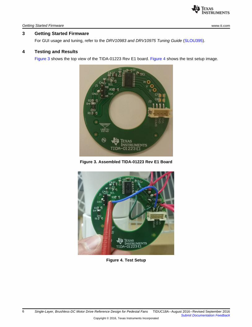
4 Testing and ResultsFigure 3 shows the top view of the TIDA-01223 Rev E1 board. Figure 4 shows the test setup image.
Figure 3. Assembled TIDA-01223 Rev E1 Board
Figure 4. Test Setup

www.ti.com Testing and Results
7TIDUC18A–August 2016–Revised September 2016Submit Documentation Feedback
Copyright © 2016, Texas Instruments Incorporated
Single-Layer, Brushless-DC Motor Drive Reference Design for Pedestal Fans
4.1 Functional Test—Spinning Pedestal FanFor this test, the female connector from the pedestal fan that supplies VSP, GND, and VCC wasconnected to the male header on the reference design board. The power cord from the pedestal fan wasthen attached to the wall, which begins to supply the bus voltage of 24 V.
A GUI was used during functional testing of the board to configure the parameters for the DRV10983devices to spin the specific motor.
The following images specify the configuration of parameters for the tested motor.
Start-up with initial position detection (IPD):
Figure 5. Start-up Profile

Testing and Results www.ti.com
8 TIDUC18A–August 2016–Revised September 2016Submit Documentation Feedback
Copyright © 2016, Texas Instruments Incorporated
Single-Layer, Brushless-DC Motor Drive Reference Design for Pedestal Fans
Run time:
Figure 6. Run Time at 24 V, Speed 86 Hz
Acceleration:
Figure 7. Acceleration

www.ti.com Testing and Results
9TIDUC18A–August 2016–Revised September 2016Submit Documentation Feedback
Copyright © 2016, Texas Instruments Incorporated
Single-Layer, Brushless-DC Motor Drive Reference Design for Pedestal Fans
Deceleration:
Figure 8. Deceleration
4.2 Thermal TestFigure 9 shows the thermal characterization images of the TIDA-01223 board during the testing, whichwas conducted at full speed.
The test was conducted with the following specifications:• Input voltage: 24 V• Current drawn: 1.89 ARMS
• Speed: 88 Hz• Run time: 20 min• Power consumption: 41 W
Figure 9. Thermal Image—Top Side

Testing and Results www.ti.com
10 TIDUC18A–August 2016–Revised September 2016Submit Documentation Feedback
Copyright © 2016, Texas Instruments Incorporated
Single-Layer, Brushless-DC Motor Drive Reference Design for Pedestal Fans
4.3 Speed Control TestThe PWM duty is modified after reading the speed from the DRV10983 device over I2C. To check thespeed regulation, the input control voltage was modulated from 1.23 V to 3.69 V and the speed wasmeasured. The measurements in the following Figure 10 clearly show a quick ramp-up to the maximumspeed.
Figure 10. Speed Regulation With Respect to Input Control Voltage (VSP)
www.ti.com Design Files
11TIDUC18A–August 2016–Revised September 2016Submit Documentation Feedback
Copyright © 2016, Texas Instruments Incorporated
Single-Layer, Brushless-DC Motor Drive Reference Design for Pedestal Fans
5 Design Files
5.1 SchematicsTo download the schematics, see the design files at TIDA-01223.
5.2 Bill of MaterialsTo download the bill of materials (BOM), see the design files at TIDA-01223.
5.3 PCB Layout Recommendations
5.3.1 Layout PrintsTo download the layer plots, see the design files at TIDA-01223.
5.4 Altium ProjectTo download the Altium project files, see the design files at TIDA-01223.
5.5 Gerber FilesTo download the Gerber files, see the design files at TIDA-01223.
5.6 Assembly DrawingsTo download the assembly drawings, see the design files at TIDA-01223.
6 References
1. Texas Instruments, DRV10983 12- to 24-V, Three-Phase, Sensorless BLDC Motor Drive,DRV10983 Data Sheet (SLVSCP6)
2. Texas Instruments, 24-V, 50-W BLDC Motor Sinusoidal Drive for Air Purifier Fans,TIDA-00656 User's Guide (TIDUAJ0)
7 TerminologyBLDC— Brushless DC motor
ESD— Electrostatic discharge
FETs, MOSFETs—Metal–oxide–semiconductor field-effect transistor
IGBT— Insulated gate bipolar transistor
IPD— Initial position detection
PWM— Pulse width modulation
RPM— Rotation per minute
RMS— Root mean square
VSP— Input control voltage
8 About the AuthorRUSHI DALAL is an applications engineer at Texas Instruments, where he is responsible for developingreference design solutions for motor control applications. He currently attends the University of Texas atDallas.

Revision History www.ti.com
12 TIDUC18A–August 2016–Revised September 2016Submit Documentation Feedback
Copyright © 2016, Texas Instruments Incorporated
Revision History
Revision HistoryNOTE: Page numbers for previous revisions may differ from page numbers in the current version.
Changes from Original (August 2016) to A Revision ..................................................................................................... Page
• Changed title from 24-V, 50-V BLDC Motor Sinusoidal Drive Reference Design for Pedestal Fans to Single-Layer,Brushless-DC Motor Drive Reference Design for Pedestal Fans................................................................... 1
• Deleted "50-W" from "50-W, 24-V Drive Capable of Driving Brushless DC (BLDC) Motors With Sinusoidal Commutation"in Features ................................................................................................................................. 1
• Added "Single-Layer Design Reduces Manufacturing Cost" to Features.......................................................... 1• Changed "Uses DRV10983 Three-Phase Sensorless Motor Driver With Integrated Power MOSFETs to Provide
Continuous Drive Current up to 2 A" to "Uses DRV10983 Three-Phase Sensorless Motor Driver With Integrated PowerMOSFETs to Provide Continuous Drive Current up to 2 ARMS (3-A Peak)" in Features.......................................... 1
• Added "single-layer" to "The TIDA-01223 reference design is a cost-effective, small-form-factor (SFF), single-layer, three-phase sinusoidal motor drive for brushless DC (BLDC) motors" ................................................................... 2
• Deleted " motors up to a power of 50 W at 24 V" from "The TIDA-01223 reference design is a cost-effective, small-form-factor (SFF), single-layer, three-phase sinusoidal motor drive for brushless DC (BLDC) motors" ............................. 2
• Deleted paragraph "This reference design provides a ready platform to use a 50-W inverter drive for a BLDC motor-basedpedestal fan." .............................................................................................................................. 2
• Changed the specification for the "DC input voltage" parameter from "22 V to 24 V" to "12 V to 24 V" ...................... 2• Changed "Rated power capacity" parameter to "Phase current rating"............................................................ 2• Changed the specification for the "Phase current rating" (formerly "Rated power capacity") from "50 W" to "2-ARMS (3-A
Peak)"....................................................................................................................................... 2• Changed specifications for the "Protections" parameter from "Overcurrent, overtemperature, motor lock, short circuit,
undervoltage, and voltage surge" to "Overcurrent protection, motor lock detect, voltage surge, overtemperature protection,and undervoltage lockout"................................................................................................................ 2
• Changed DRV10983 Motor Drive Schematic to updated image .................................................................... 4• Added subsection Single-Layer PCB Design.......................................................................................... 5

IMPORTANT NOTICE FOR TI REFERENCE DESIGNS
Texas Instruments Incorporated (‘TI”) reference designs are solely intended to assist designers (“Designer(s)”) who are developing systemsthat incorporate TI products. TI has not conducted any testing other than that specifically described in the published documentation for aparticular reference design.TI’s provision of reference designs and any other technical, applications or design advice, quality characterization, reliability data or otherinformation or services does not expand or otherwise alter TI’s applicable published warranties or warranty disclaimers for TI products, andno additional obligations or liabilities arise from TI providing such reference designs or other items.TI reserves the right to make corrections, enhancements, improvements and other changes to its reference designs and other items.Designer understands and agrees that Designer remains responsible for using its independent analysis, evaluation and judgment indesigning Designer’s systems and products, and has full and exclusive responsibility to assure the safety of its products and compliance ofits products (and of all TI products used in or for such Designer’s products) with all applicable regulations, laws and other applicablerequirements. Designer represents that, with respect to its applications, it has all the necessary expertise to create and implementsafeguards that (1) anticipate dangerous consequences of failures, (2) monitor failures and their consequences, and (3) lessen thelikelihood of failures that might cause harm and take appropriate actions. Designer agrees that prior to using or distributing any systemsthat include TI products, Designer will thoroughly test such systems and the functionality of such TI products as used in such systems.Designer may not use any TI products in life-critical medical equipment unless authorized officers of the parties have executed a specialcontract specifically governing such use. Life-critical medical equipment is medical equipment where failure of such equipment would causeserious bodily injury or death (e.g., life support, pacemakers, defibrillators, heart pumps, neurostimulators, and implantables). Suchequipment includes, without limitation, all medical devices identified by the U.S. Food and Drug Administration as Class III devices andequivalent classifications outside the U.S.Designers are authorized to use, copy and modify any individual TI reference design only in connection with the development of endproducts that include the TI product(s) identified in that reference design. HOWEVER, NO OTHER LICENSE, EXPRESS OR IMPLIED, BYESTOPPEL OR OTHERWISE TO ANY OTHER TI INTELLECTUAL PROPERTY RIGHT, AND NO LICENSE TO ANY TECHNOLOGY ORINTELLECTUAL PROPERTY RIGHT OF TI OR ANY THIRD PARTY IS GRANTED HEREIN, including but not limited to any patent right,copyright, mask work right, or other intellectual property right relating to any combination, machine, or process in which TI products orservices are used. Information published by TI regarding third-party products or services does not constitute a license to use such productsor services, or a warranty or endorsement thereof. Use of the reference design or other items described above may require a license from athird party under the patents or other intellectual property of the third party, or a license from TI under the patents or other intellectualproperty of TI.TI REFERENCE DESIGNS AND OTHER ITEMS DESCRIBED ABOVE ARE PROVIDED “AS IS” AND WITH ALL FAULTS. TI DISCLAIMSALL OTHER WARRANTIES OR REPRESENTATIONS, EXPRESS OR IMPLIED, REGARDING THE REFERENCE DESIGNS OR USE OFTHE REFERENCE DESIGNS, INCLUDING BUT NOT LIMITED TO ACCURACY OR COMPLETENESS, TITLE, ANY EPIDEMIC FAILUREWARRANTY AND ANY IMPLIED WARRANTIES OF MERCHANTABILITY, FITNESS FOR A PARTICULAR PURPOSE, AND NON-INFRINGEMENT OF ANY THIRD PARTY INTELLECTUAL PROPERTY RIGHTS.TI SHALL NOT BE LIABLE FOR AND SHALL NOT DEFEND OR INDEMNIFY DESIGNERS AGAINST ANY CLAIM, INCLUDING BUT NOTLIMITED TO ANY INFRINGEMENT CLAIM THAT RELATES TO OR IS BASED ON ANY COMBINATION OF PRODUCTS ASDESCRIBED IN A TI REFERENCE DESIGN OR OTHERWISE. IN NO EVENT SHALL TI BE LIABLE FOR ANY ACTUAL, DIRECT,SPECIAL, COLLATERAL, INDIRECT, PUNITIVE, INCIDENTAL, CONSEQUENTIAL OR EXEMPLARY DAMAGES IN CONNECTION WITHOR ARISING OUT OF THE REFERENCE DESIGNS OR USE OF THE REFERENCE DESIGNS, AND REGARDLESS OF WHETHER TIHAS BEEN ADVISED OF THE POSSIBILITY OF SUCH DAMAGES.TI’s standard terms of sale for semiconductor products (http://www.ti.com/sc/docs/stdterms.htm) apply to the sale of packaged integratedcircuit products. Additional terms may apply to the use or sale of other types of TI products and services.Designer will fully indemnify TI and its representatives against any damages, costs, losses, and/or liabilities arising out of Designer’s non-compliance with the terms and provisions of this Notice.IMPORTANT NOTICE
Mailing Address: Texas Instruments, Post Office Box 655303, Dallas, Texas 75265Copyright © 2016, Texas Instruments Incorporated