simulink impedance controller for barrett wam · existing system •wam connected to xpc target...
TRANSCRIPT
Simulink Impedance Controller for Barrett WAM
Chris Jordan
Overview
• Summary of the existing System
• Theory of Impedance Control
• Current Implementation
• Demo
• Implementation Problems

Existing System
• WAM connected to XPC Target machine using CAN communication
• Program in MATLAB Simulink (on i7 machine) and download code to XPC target to be run in real-time
• Send UDP commands from i7 machine (or potentially DVC) to XPC target to move arm
i7 Machine XPC Target
Joint Torques
Joint Angles
Compiled Simulink Code
UDP commands
Position Info

Simulink Block Diagram

Force Controller
• Objective: Tool interacts with environment and is subject to forces/moments. Force controllers deal with how to compensate during these interactions
• Example: robotic arm writing with a pencil, or during a grasp with the object

𝐹𝑡𝑜𝑜𝑙Matrix
• 𝐹𝑡𝑜𝑜𝑙 =
𝑓𝑜𝑟𝑐𝑒𝑥𝑓𝑜𝑟𝑐𝑒𝑦𝑓𝑜𝑟𝑐𝑒𝑧
𝑚𝑜𝑚𝑒𝑛𝑡𝑥𝑚𝑜𝑚𝑒𝑛𝑡𝑦𝑚𝑜𝑚𝑒𝑛𝑡𝑧
• In base coordinates
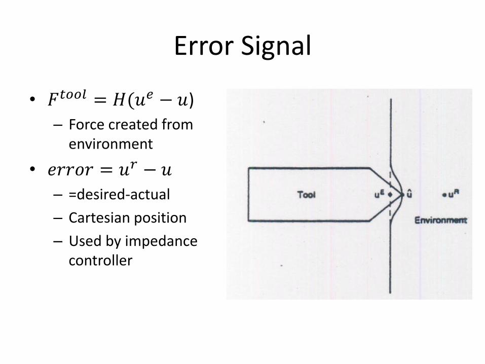
Error Signal
• 𝐹𝑡𝑜𝑜𝑙 = 𝐻(𝑢𝑒 − 𝑢)
– Force created from environment
• 𝑒𝑟𝑟𝑜𝑟 = 𝑢𝑟 − 𝑢
– =desired-actual
– Cartesian position
– Used by impedance controller

Derivation of Manipulator Jacobian
• 𝐽 𝑞 =𝐴(𝑞)𝐵(𝑞)
– 𝐴 𝑞 =𝑑𝑝 𝑞
𝑑𝑞𝑘for k=1:n
– B(q)=third column of each rotation matrix from 0 to n-1 • [0; 0; 0] if a prismatic joint

Theory of Impedance Controllers
• 𝑑𝑢 = 𝐽 𝑞 𝑑𝑞 – Infinitesimal tool displacement= Jacobian * infinitesimal Joint
displacement
• 𝐹𝑡𝑜𝑜𝑙 = 𝐾𝑑𝑢 – K is the spring constant (determines “Stiffness”) – If large, the controller is similar to PD – Should be selected relative to the environment
• 𝑑𝑢 = 𝑒 = 𝑟 − 𝑢
• 𝜏 = 𝐽𝑇 𝑞 ∗ 𝐹𝑡𝑜𝑜𝑙 – A force at the end effector exerts these torques on each joint
• 𝝉 = 𝑱𝑻 𝒒 ∗ 𝑲𝒆 + 𝑳𝒆′ + 𝒉 𝒒 – Where h(q) is gravity compensation

Block Diagram

Simulink Controller

Current Implementation
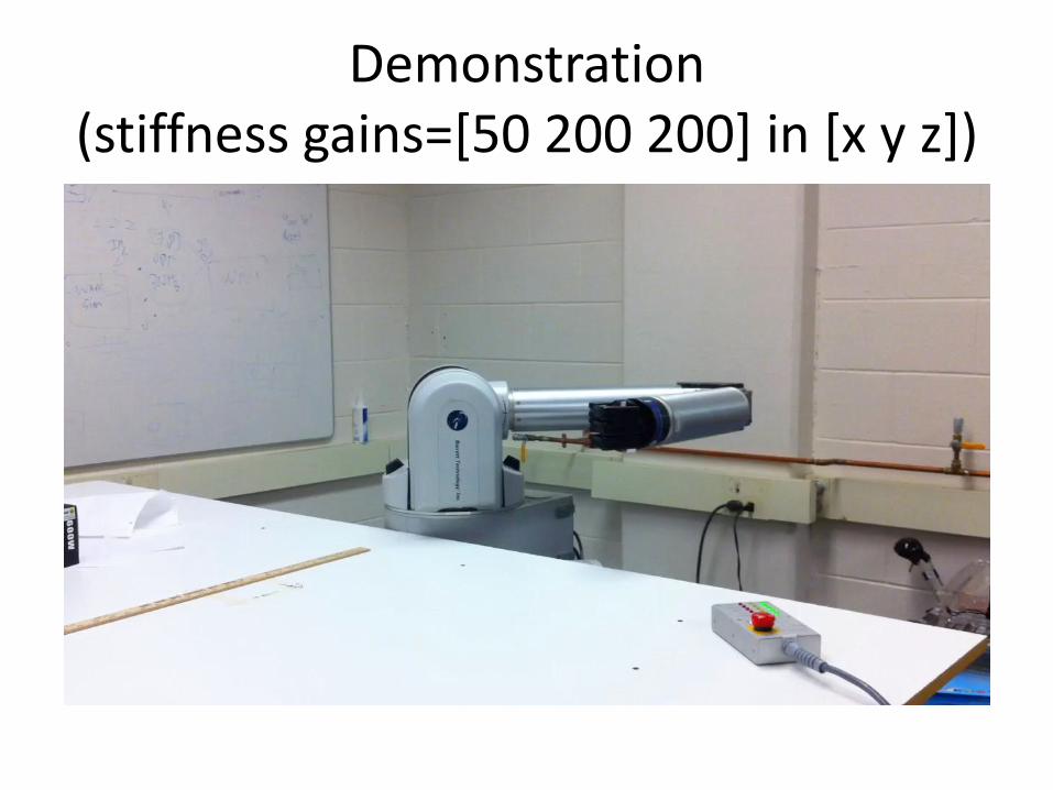
Demonstration (stiffness gains=[50 200 200] in [x y z])

Sample Data
15 20 25 30 35 400
0.1
0.2
0.3
0.4
0.5
0.6
0.7
0.8
Position in X
15 20 25 30 35 40-10
-5
0
5
10
15
Torque Joint 1

Implementation Problems
• Integration with existing system
– Problems with the current task planner
• Orientation Support

Future Works
• Fix minor bugs
– Integration with the task planner
– Problem with mask implementation
• Add support for orientation
• Add ability to change stiffness and damping gains over UDP
• Debug system

Questions?