simulations investigating curved departure and arrival
TRANSCRIPT

Simulations investigating curved departure and arrival procedures using GNSS based vertical guidance
Behrend, Ferdinand Technical University Berlin
Berlin, Germany [email protected]
De Smedt, David EUROCONTROL Brussels, Belgium
Abstract— Building further on previous PBN to precision final approach transition work such as Radius-to Fix (RF) in extended terminal area procedures EUROCONTROL in collaboration with the Technical University of Berlin (TUB) and under the SESAR 1 2020 work programme conducted an extensive flight simulation series. It complements previous studies by addressing the use of RF leg in high altitudes and during the departure phase of flight. In addition, a concept of using GNSS altitude for vertical navigation during curved transitions to final approach was researched. The study was performed via a set of flight simulations using professional flight simulators of various aircraft types (Airbus A340-300, Boeing 777-200, Boeing 737-300, Embraer 190, Bombardier CS100 and De Havilland Bombardier DHC-8-Q400). The tracking of the procedures containing RF legs at all altitudes was excellent in all evaluated aircraft types. Data analysis has shown that at the higher altitudes, the aircraft could reach the start of the RF at various altitudes, thus the design of the procedure should take into account the most conservative aircraft ground speed. Also, during departure phase, the RF leg was tracked with good precision by all aircraft types tested and for various take-off weights. Nevertheless, recorded data showed that individual aircraft performance had a great influence on the altitude the aircraft reached at the start of the turn, causing some aircraft to start turning well below the minimum altitudes that are applied in current procedure design criteria. Analysis of Required Navigation Performance (RNP) transition to Instrument Landing System (ILS), commonly abbreviated ‘RNP transition to ILS’ with additional transition from barometric to geometric altitude using GNSS in the initial and intermediate approach phases has been evaluated. It enables smooth continuous descents and final approach glide path intercepts without the need for a straight intermediate segment between localiser and glide path intercept. The flight deck implementation of geometric altitude in the terminal area still requires some considerations. On the other hand, the use of geometric altitude will require a clear operational concept for practical implementation in an Air Traffic Management (ATM) environment.
Keywords—RF-Leg, GNSS-based Vertical Guidance, Extended Terminal Area, PBN, Curved Segment Approaches, Flight Simulations, Full Flight Simulator
I. INTRODUCTION
The simulation series was performed in the frame of Horizon 2020 PJ.02 Solution 11 (PJ.02-11) – “Enhanced Terminal Area for efficient curved operations”.The objective of PJ.02-11 is to develop and validate a concept of operation for enhanced terminal area operation through the application of
1 Single European Sky ATM Research
GNSS (Global Navigation Satellite System) usage extended to the TMA (Terminal Manoeuvring Area).
Enhanced Terminal Area for efficient curved operations refers to curved segment approaches as close to the runway as possible to optimise procedures in terms of fuel consumption or noise abatement. The use of geometric vertical navigation guidance in the TMA (outside the Final Approach segment) will remove the workload associated with barometric to geometric vertical navigation transition for both flight crew and Air Traffic Controllers (ATCOs) and improve situational awareness (Safety and Human Performance benefit).
This SESAR solution addresses curved operations. The Radius-to-Fix (RF) functionality is a feature available in all modern aircraft Flight Management Systems (FMS) today allowing the aircraft to make a turn with a constant radius over the earth. Previously, the RF leg was primarily used close to the airport during arrival and approach phase. In a high density complex TMA the use of RF leg can provide added value in designing Standard Instrument Departures (SIDs), Standard Terminal Arrival Routes (STARs) and en-route transitions with precise, repeatable turns. For this reason, the feasibility and performance of the RF leg function was evaluated at various altitudes and flight phases in the extended TMA.
The PJ.02 Solution 11 project team decided to extend scope of the concept to also consider curved operations in the departure phase of flight. Therefore the use of RF leg was investigated also for departures. This SESAR solution addresses also the use the geometric altitude. In today’s operation, the vertical navigation in the TMA is based on the barometric altitude. Currently the GNSS based (GBAS/SBAS) geometric vertical guidance is only used during Final Approach phase of flight. The PJ.02 Solution 11 project investigates how to extend the use of geometrical altitude and geometric vertical guidance to TMA operations.
The purpose of the set of flight simulations presented in this paper was to extend the scope of the previous simulations conducted in SESAR 1 projects WP9.9 and WP6.8.8 using the RF-functionality only at low altitude operations during approach.The application of the RF leg function was expanded to all altitudes in the extended TMA so that curved operations can be implemented anywhere in the arrival and approach phase (and not only in the transition to Final Approach). The feasibility and performance of this function was evaluated by designing an ARINC 424 procedure containing curved paths at various altitudes in the extended TMA, loading these procedure in the different aircraft types by using manufacturer specific databases and flying the procedures while recording data.

In addition the application of curved departures was investigated with the start of the curved path immediately at the departure end of the runway (DER). This allows for efficient departure routes, the possibility to avoid noise sensitive areas thanks to an early turn and potentially increased runway throughput.
The provision of GNSS based altitude was investigated via two options. A function was developed in the flight simulator environment which allowed switching the vertical navigation from using barometric altitude to GNSS based altitude. The geometric altitude was fed to the auto-flight control system for vertical guidance. This switch was to be made once the aircraft was cleared for the approach and the pilot was allowed to descent to the Decision Altitude while respecting all published intermediate altitudes in the procedure. The operational feasibility to replace the barometric altitude indication with a GNSS based altitude and to take GNSS based altitude into account for the guidance of the aircraft, was evaluated. An alternative concept was also investigated in which GNSS altitude was provided to the pilot on an additional display.
The above research topics were tested on a range of different professional aircraft flight simulators, so that the conclusions are as generic as possible and not aircraft type specific. The trajectory data from the different aircraft types were collected during the simulations and recommendations regarding procedure design and the concept of operation (taking into account aircraft performance and flight crew workload) are formulated.
II. SIMULATOR SET UP
A. Radius to Fix (RF) Functionality
Radius-to-Fix (RF) functionality is a feature available in all modern aircraft FMS today. It was introduced by many manufacturers in their systems around the year 2000. It allows the definition of a curved ground track, which will be accurately tracked by the aircraft’s flight guidance functions. It can be coded in the aircraft’s database as an ARINC 424 path terminator for SID and STAR terminal areas procedure, including SID and STAR en-route transitions, and approaches. It is defined by a starting and ending waypoint and a radius. The RNP systems supporting this leg type provide the same ability to conform to the track-keeping accuracy during the turn as in the straight line segments. RF legs provide a predictable and repeatable ground track during a turn and prevent the dispersion of tracks experienced in other types of turn construction due to varying aircraft speeds, turn anticipation, bank, roll rate, etc. Therefore, RF legs can be employed where a specified path must be flown during a turn.
B. Simulators and Aircraft Types
All the simulations sessions within the project were performed in full flight simulators that are normally used for pilot training. These simulators are full motion Full Flight Simulators, certified according to EASA CS-FSTD Level D. The Level D represents the highest grade of flight simulator certification and provides the best level of realism. The flight simulators are operated by Lufthansa Aviation Training and are
located at the training centres in Frankfurt, Vienna and Berlin. Table 1 below illustrates the aircraft types which were part of the simulation series:
TABLE I. AIRCRAFT TYPES USED DURING SIMULATIONS
Aircraft type FMS Paper Abbreviation Airbus A340-300 Honeywell Pegasus A340 Boeing 777-200ER Honeywell AIMS system
with integrated FMS B777
Boeing 737-300 GE Smith Load 10.X B737 Bombardier Dash 8 Q400
Universal UNS-1 Q400
Bombardier CS100 Rockwell Collins Pro Line Fusion
CS100
Embraer 190 Honeywell Primus Epic E 190
The flight characteristics of the simulators correspond to the existing reference aircraft in order to ensure a realistic behaviour of the whole aircraft system. Therefore the simulators are partly equipped with real avionics (e.g. FMS, Automatic Flight Control System (AFCS)) from the corresponding manufacturer. Within the overall system architecture, the original aircraft components are stimulated by the simulation host via the corresponding ARINC interface (software-hardware-in the loop – principle). Consequently, the reaction of the simulated aircraft during the trials complies with the reaction of the real aircraft.
The simulators offer the possibility to use a tailored Navigation Database prepared as an ARINC 424 file by EUROCONTROL and TUB engineers .The A340, B777 and B737 simulators additionally offering a unique datarecording functionality to record a pre-defined set of simulator values (labels) at 15 HZ. Furthermore, for all simulators, video recordings of the Primary Flight Display and the Navigation Display were provided.
C. GNSS-Altitude for auto-flight
Vertical guidance based on GNSS-altitude was implemented as an additional functionality of the Automatic Flight Control System (AFCS) for the A340 and the B737simulator. As an option controlled via a software-based switch, the source for the vertical flight guidance could be switched from barometric altitude to geometrical altitude.
The air data module of the simulators was enhanced with a functionality to use the geometric altitude provided by the simulation – instead of the barometric altitude output. The function could be activated during flight from inside the flight compartment. After activation, all corresponding systems were now using the geometric altitude instead of the barometric altitude. After activating the switch the AFCS would provide vertical guidance based on the reference path of the selected instrument flight procedure and the geometric altitude. This way any altitude deviation resulting from the presence of a non-standard ISA reference temperature on the ground was eliminated by the use of the geometric altitude.

D. GNSS Altitude as Additional Display
The provision of GNSS altitude information was also implemented through an additional display for some of the simulation scenarios. Two options were implemented:
• Display of the actual geometrical altitude, available on A340, B737, B777, E190 and Q400
• Display of the vertical deviation between the reference path and the geometrical altitude, available on A430 and B737
The additional display was positioned next to the PFD. Now the pilot could use the additional altitude information to enhance situational awareness regarding the actual vertical position in comparison to the reference path, without any temperature-induced deviation. The pilot was able to correct the vertical path of the aircraft by using the selected-modes for rate of descent / flight path angle of the AFCS.
Figure 1 shows the additional display as used in the A340 simulator. The upper value represents the geometric altitude, the lower value the deviation between the vertical reference path of the selected instrument flight procedure and the actual geometric altitude (VDev).
To further enhance the additional display providing GNSS altitude information, an additional VDev module was added to the Host-computer. This module compares the actual three-dimensional geometrical position of the aircraft with the corresponding vertical position of the selected instrument flight procedure within the FMS. The calculated vertical deviation could be presented in real-time on the additional display (A340 and B737).
Fig. 1. Additional Display with VDev and Geo-Alt in A340
III. EXPERIMENTAL SET UP
A. Procedure Design
Procedures were developed to test curved paths during departure, en-route and arrival phase of flight at all altitudes. A fictive airport was created based on the layout of Munich
airport, which was called EDZA with runway 08R. The arrival procedures were based on procedures designs which were already used in SESAR 1 projects 6.8.8 and 9.9 [1][2][3][4]. Three specific designs were retained from those projects with the following procedure names:
• MUNI3A: arrival procedure with an RF leg between MU313 and IF003 with a radius of 1.5 NM, connected to a 3 NM long final ILS segment
• MUNI6A: arrival procedure with an RF leg between MU613 and IF006 with a radius of 2.3 NM, connected to a 6 NM long final ILS segment
• MUNI9A: arrival procedure with an RF leg between MU613 and IF009 with a radius of 2.8 NM, connected to a 9 NM long final ILS segment
Those procedures are graphically displayed in Figure 2. The arrival procedures were designed as STARs while the 3 final approaches of respectively 3, 6 and 9 NM Final Approach length, were designed as ILS approaches. Altitude constraints were coded at points MU312, MU313 and IF003 in the MUNI3A procedure, such that the resulting vertical direct path between those points had a 2 degree slope. This enabled a transition from a 2 degree initial descent path to 3 degree final descent on the ILS glide path. The same was done at points MU612, MU613 and IF006 for MUNI6A and at points MU912, MU913 and IF009 for MUNI9A. To limit path excursions, respecting the aircrafts bank angle limitation for the design turn radius, a speed constraint in knots (kts) was imposed at the start point of the RF turn, with the following magnitude:
• MUNI3A: maximum 180 kts at MU313
• MUNI6A: maximum 200 kts at MU613
• MUNI9A: maximum 220 kts at MU913
Fig. 2. MUNI3A, MUNI6A and MUNI9A arrival procedures
As it was the objective to test the applicability of the RF leg function at all flight altitudes, two new procedures were designed: MUNI1A and MUNI2A, which are illustrated in Figure 3. MUNI1A is a departure procedure designed as SID, which connects to MUNI2A which is an arrival procedure designed as STAR. The end of MUNI2A (waypoints MU611, MU612, MU613, IF006) is identical to MUNI6A, thus the

arrival procedure connecting via an RF leg to a 6 NM final, with identical altitude and speed constraints.
All the turns in MUNI1A and MUNI2A are RF turns. The objective is to fly the MUNI1A departure procedure connected to the MUNI2A arrival procedure as a continuous climb from the runway to cruise altitude, followed by a continuous descent from cruise altitude to touchdown. The changeover-point from SID to STAR is at waypoint MU008 where the last RF turn of the SID transitions into the first RF turn of the STAR. Therefore these two RF turns have the same radius.
Fig. 3. MUNI1A departure and MUNI2A arrival procedures
The required turn radius (R) can be computed from the target groundspeed (GS), the gravitation constant (g = 9.81m/s2) and the assumed aircraft maximum bank angle ϴ as follows:
R=(GS)2/(g·tanϴ)
The target GS was computed starting from a realistic Mach-Calibrated Airspeed (Mach-CAS) schedule from climb and descent, e.g. 0.84 / 320kts. Based on the location of the turn and the anticipated distance flown for climb and the distance to go for descent, a design altitude was computed at the start and end points of each turn. Using this design altitude and the Mach-CAS schedule, the True Airspeed could be estimated at the start and end of each turn, to which a design tailwind as described in ICAO PANS-OPS Vol II (doc 8168) was added [5]. The design tailwind increased linearly from 47kts on ground to 127kts at 40000ft, with a rate of 2kts per 1000ft of altitude. This resulted in a design GS for each turn. Assuming a maximum bank angle for each turn and using the design GS, a turn radius could be calculated for each turn. Table 2 provides an overview of the turns in the MUNI1A and MUNI2A procedures, with indicated turn number, procedure name, distance flown, design GS, assumed maximum bank angle and resulting design radius.
The first turn of the MUNI1A departure procedure is an RF turn which starts immediately overhead the DER. The turn consists of a 90 degree track change using a turn radius of 2 NM, assuming 220 kts of maximum GS and a maximum bank angle of 20 degrees. Currently ICAO PAN-OPS Vol II doc 8168 requires at least 1 NM distance to the DER to start the RF-Leg.
TABLE II. RADIUS FOR EACH TURN IN MUNI1A AND MUNI 1B PROCEDURES IN FUNCTION OF DESIGN GS AND DESIGN BANK ANGLE
Turn No.
PROCEDURE Dist. (NM)
GS (kts) BANK (°) R (NM)
1 MUNI1A 2,2 220 20 2,0
2 MUNI1A 12,3 350 20 5,0
3 MUNI1A 46,7 500 20 10,0
4 MUNI1A 92,4 600 15 20,0
5 MUNI2A 123,8 600 15 20,0
6 MUNI2A 165,2 600 20 15,0
7 MUNI2A 188,8 500 20 10,0
8 MUNI2A 229,4 240 20 2,3
One of the objectives of the current project was to see if the aircraft can make the RF turn immediately at the DER. This would require sufficient climb performance for the aircraft the reach the DER above the minimum engagement altitude for lateral flight guidance, which is required to provide path steering during the RF leg. To avoid path excursions, a speed constraint was imposed at the first waypoint of the RF (thus the DER) with a magnitude of 180 kts. A close-up illustration of the first section of the MUNI1A departure procedure with the RF turn at the DER is provided in Figure 4. An early turn after departure with fixed ground track, could provide environmental benefits (noise reduction by avoiding overflying noise sensitive areas) as well as increased runway throughput by allowing light, slow aircraft to turn away from the departure direction of following faster aircraft.
Fig. 4. First part of MUNI1A departure procedure
Furthermore, an additional arrival procedure were created: MUNI2B as illustrated in Figure 5. MUNI2B is an arrival procedure designed as STAR, with a 180 degree RF turn using a radius of 2.3 NM which ends at the final approach axis, at a distance of 5 NM from the threshold. At 5 NM from the threshold, the procedure connects to an approach procedure consisting of a 3 NM final segment with a glide path of 3

degrees preceded by a 2 NM long intermediate segment aligned with the final approach axis. This represents the “classic” design as described in ICAO PANS-OPS Vol II (doc. 8168) [5]. Altitude constraints were put at the start and end point of the 2 NM intermediate segment, creating a 2 degree vertical gradient. The idea of this procedure is to verify how a classic design can be used to fly efficient Performance Based Navigation (PBN) to xLS procedures enabling a continuous descent path without level off, in above ISA conditions and without the use of GNSS based altitude.
Fig. 5. MUNI2B arrival procedure
B. Simulator Set Up
For the implementation of GNSS altitude in the initial approach flight phase, the following different cockpit set-ups were available:
• Standard
o Barometric altitude on PFD
o Flight Guidance based on barometric altitude
o No additional display
• ADC switch
o Geometric altitude on PFD (*)
o Flight Guidance based on geometric altitude
o No additional Display
• Additional Display Basic
o Geometric Altitude displayed
o Altitude-Distance table for Pilot Monitoring (PM) to check manually VDev
• Additional Display Advanced
o Geometric Altitude displayed
o Vertical Deviation displayed based on geometric altitude
• ADC switch and Additional Display Advanced
o Geometric altitude on PFD (*)
o Flight Guidance based on geometric altitude
o Geometric Altitude displayed
o Vertical Deviation displayed based on geometric altitude
(*) Note that on the B737 the altitude indicated on the aircraft altimeter remained barometric, as the aircraft altimeter is a conventional (mechanical) instrument which could not be modified.
Table III shows the availability of the cockpit set-up options within the used simulators.
TABLE III. AVAILABLE COCKPIT SET-UPS
Aircraft Type
Standard ADC Switch Basic DisplayADC switch + Advanced Display
A340 B737 B777 Q400 E190
CS 100
The “Standard” set-up was used as baseline scenario – the aircraft was guided by the barometrical altitude with a temperature induced vertical error dependent on the inserted ISA temperature deviation. No additional information was available to the pilot to provide situation awareness regarding the vertical position error.
The “ADC switch” scenario offered the possibility to change vertical guidance to geometrical altitude. Any temperature-based vertical deviation was now corrected by the Autopilot/Flight Guidance system. In the A340 the pilot would see the barometrical altitude replaced by the geometrical altitude on the PFD. In the B737, as the altimeter is a conventional instrument, the altimeter reading remained barometric.
During the “Additional Display Basic” scenario the pilot was provided with the geometrical altitude via an additional display. By using a conventional altitude-distance table – as available for non-precision approaches RNAV(GNSS) to Lateral Navigation (LNAV) minima, LOC/DME, VOR/DME and NDB/DME – the Pilot Monitoring (PM) was able to give call outs regarding the vertical deviation between the actual geometrical altitude and the reference path. The Pilot-Flying (PF) could correct the vertical path using the selected vertical modes based on the call-outs of the PM.
Using the “Additional Display Advanced” scenario the PF could adjust the vertical path of the aircraft based on the provided VDev information. The VDev information – based on geometrical altitude to the reference path – was displayed consistently during the approach in real-time offering the possibility to correct the vertical path more precisely.
Within the “ADC switch and Additional Display Advanced” scenario the Autopilot/Flight Guidance system used the geometrical altitude for flight guidance and an additional display with both indications – geometrical altitude and VDev – was available to the pilot. In the A340 the pilot would see the barometrical altitude replaced by the geometrical altitude on the PFD. In the B737, as the altimeter is a conventional instrument, the altimeter reading remained barometric.
IV. RESULTS
A. General
The procedures were tested following a predefinded schedule using all available set-ups on the following six aircraft types: Airbus A340-300, Boeing B777-200ER, Boeing B737-300, Bombardier CS100, Embraer 190 and De Havilland (Bombardier) Dash-8-Q400. The wind magnitude implemented in the simulator during the tests was zero on the ground increasing linearly to 100 kts at 30000 ft with directions from 170° and 350°. The temperature was either 35 or 40 degrees on ground which means ISA + 23 or ISA + 28 conditions for an airport elevation of 1500ft.
B. Video Recordings
Video recordings were made during each test. They were used for general assessment of the correct display of the procedure and fly-ability. In terms of correct loading, display and fly-ability of the procedures, the following observations were made:
• RF turns were flyable at all altitudes and flight phases. Thus, the use of the function should not be restricted to low altitudes only. The turn radius however should be carefully designed in function of target maximum GS and maximum bank angle for the range of altitudes in which the aircraft could fly during the RF leg
• The coding of the leg preceding an RF leg starting at the DER requires attention. This study recommends using a CF leg as a starting path terminator with course equal to the runway axis (QFU) ending at the start waypoint of the RF (which corresponds to the DER). The use of a TF path terminator starting at the runway threshold and ending at the start waypoint of the RF (which corresponds to the DER) did not work in all tested systems
• The connection of a STAR with an RF leg at the end to a SID with an RF leg at the start, which is the case of the MUNI1A SID connected to the MUNI2A STAR with common waypoint MU008 caused trouble in some aircraft types. When the MUNI1A SID was loaded individually there was no issue and the last RF leg in the SID could be flown. The most probably reason is the missing leg preceding the first RF turn in the MUNI2A STAR. Actually, the coding sequence starts with an IF which is the first waypoint of the RF path terminator. Consequently, this study recommends not commencing a procedure with an IF followed directly by an RF leg.
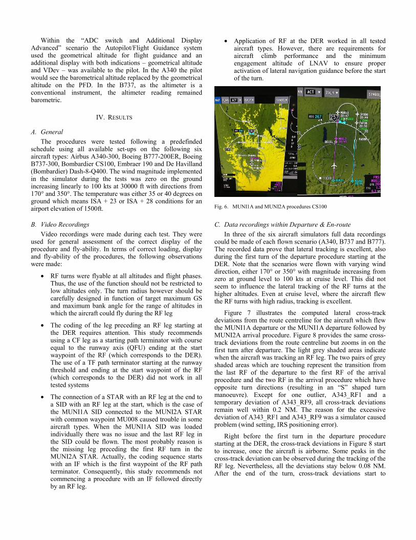
• Application of RF at the DER worked in all tested aircraft types. However, there are requirements for aircraft climb performance and the minimum engagement altitude of LNAV to ensure proper activation of lateral navigation guidance before the start of the turn.
Fig. 6. MUNI1A and MUNI2A procedures CS100
C. Data recordings within Departure & En-route
In three of the six aircraft simulators full data recordings could be made of each flown scenario (A340, B737 and B777). The recorded data prove that lateral tracking is excellent, also during the first turn of the departure procedure starting at the DER. Note that the scenarios were flown with varying wind direction, either 170° or 350° with magnitude increasing from zero at ground level to 100 kts at cruise level. This did not seem to influence the lateral tracking of the RF turns at the higher altitudes. Even at cruise level, where the aircraft flew the RF turns with high radius, tracking is excellent.
Figure 7 illustrates the computed lateral cross-track deviations from the route centreline for the aircraft which flew the MUNI1A departure or the MUNI1A departure followed by MUNI2A arrival procedure. Figure 8 provides the same cross-track deviations from the route centreline but zooms in on the first turn after departure. The light grey shaded areas indicate when the aircraft was tracking an RF leg. The two pairs of grey shaded areas which are touching represent the transition from the last RF of the departure to the first RF of the arrival procedure and the two RF in the arrival procedure which have opposite turn directions (resulting in an “S” shaped turn manoeuvre). Except for one outlier, A343_RF1 and a temporary deviation of A343_RF9, all cross-track deviations remain well within 0.2 NM. The reason for the excessive deviation of A343_RF1 and A343_RF9 was a simulator caused problem (wind setting, IRS positioning error).
Right before the first turn in the departure procedure starting at the DER, the cross-track deviations in Figure 8 start to increase, once the aircraft is airborne. Some peaks in the cross-track deviation can be observed during the tracking of the RF leg. Nevertheless, all the deviations stay below 0.08 NM. After the end of the turn, cross-track deviations start to
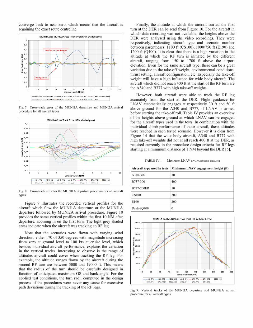
converge back to near zero, which means that the aircraft is regaining the exact route centreline.
Fig. 7. Cross-track error of the MUNI1A departure and MUNI2A arrival procedure for all aircraft types
Fig. 8. Cross-track error for the MUNI1A departure procedure for all aircraft types
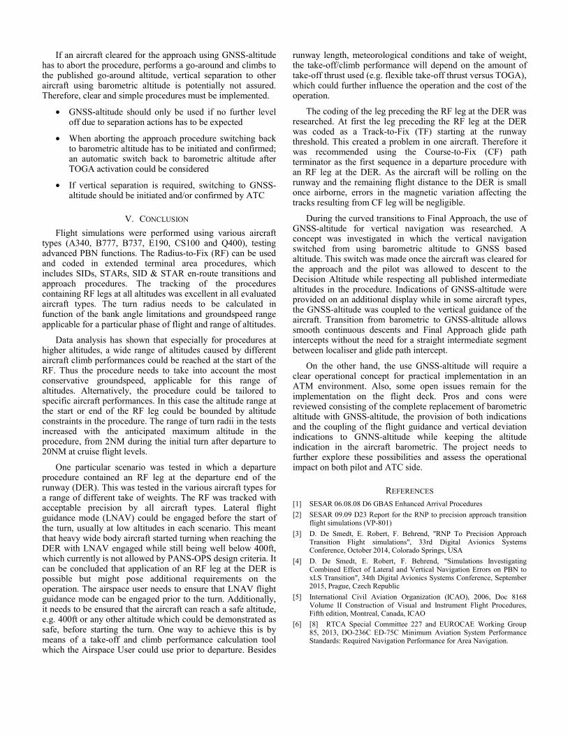
Figure 9 illustrates the recorded vertical profiles for the aircraft which flew the MUNI1A departure or the MUNI1A departure followed by MUNI2A arrival procedure. Figure 10 provides the same vertical profiles within the first 10 NM after departure, zooming in on the first turn. The light grey shaded areas indicate when the aircraft was tracking an RF leg.
Note that the scenarios were flown with varying wind direction, either 170 of 350 degrees with magnitude increasing from zero at ground level to 100 kts at cruise level, which besides individual aircraft performance, explains the variation in the vertical tracks. Interesting to observe is the range of altitudes aircraft could cover when tracking the RF leg. For example, the altitude ranges flown by the aircraft during the second RF turn are between 5000 and 19000 ft. This means that the radius of the turn should be carefully designed in function of anticipated maximum GS and bank angle. For the applied test conditions, the turn radii computed in the design process of the procedures were never any cause for excessive path deviations during the tracking of the RF legs.
Finally, the altitude at which the aircraft started the first turn at the DER can be read from Figure 10. For the aircraft in which data recording was not available, the heights above the DER were analysed using the video recordings. They were respectively, indicating aircraft type and scenario number between parentheses: 1100 ft (CS100), 1000/750 ft (E190) and 1200 ft (Q400). It is clear that there is a high variation in the altitude at which the RF turn is initiated by the different aircraft, ranging from 150 to 1700 ft above the airport elevation. Even for the same aircraft type, there can be a great variation due to the take-off weight, environmental conditions, thrust setting, aircraft configuration, etc. Especially the take-off weight will have a high influence for wide body aircraft. The aircraft which did not reach 400 ft at the start of the RF turn are the A340 and B777 with high take-off weights.
However, both aircraft were able to track the RF leg accurately from the start at the DER. Flight guidance for LNAV automatically engages at respectively 30 ft and 50 ft above ground for the A340 and B777, if LNAV is armed before starting the take-off roll. Table IV provides an overview of the heights above ground at which LNAV can be engaged for the aircraft types used in the tests. In combination with the individual climb performance of those aircraft, these altitudes were reached in each tested scenario. However it is clear from Figure 14 that the wide body aircraft, A340 and B777 with high take-off weights did not at all reach 400 ft at the DER, as required currently in the procedure design criteria for RF legs starting at a minimum distance of 1 NM beyond the DER [5].
TABLE IV. MINIMUM LNAV ENGAGEMENT HEIGHT
Aircraft type used in tests Minimum LNAV engagement height (ft)
A340-300 30
B737-300 400
B777-200ER 50
CS100 200
E190 200
Dash-8Q400 0
Fig. 9. Vertical tracks of the MUNI1A departure and MUNI2A arrival procedure for all aircraft types

Fig. 10. Vertical tracks of the MUNI1A departure procedure for all aircraft types
D. Data recordings within Approach
Data recordings were made for all approaches flown in the A340, B737 and B777 aircraft types. On the A340 and B737 the ADC switch concept was implemented, providing the possibility to change the output of the ADC from barometric altitude to geometric (GNSS based) altitude. As this output is used by the AFCS, vertical guidance based on geometric altitude was available. In the B777, only an additional display with GNSS based altitude was available.
Note that the graphs displaying the lateral and vertical flight tracks also display the reference trajectory (flight plan). The vertical track represents the real track flown above ground. Note that the output of the altitude displayed on the PFD which could be extracted from the simulator is also presented. Whenever the ADC switch concept was used, a discontinuity in the displayed PFD altitude appeared as the source of this altitude switched from barometric to geometric
In the A340, the aircraft was flown using vertically selected modes during the STAR before intercepting the glide path. This is because the managed descent function in Airbus does currently not generate a constant geometric slope between subsequent altitude constraints at and just before the glide path intercept point, which was the objective of the simulation.
The use of GNSS altitude, preferably coupled to the AFCS was very useful to enable the aircraft to fly a vertical path without disturbances due to temperature deviations from ISA and to allow stable glide path intercept. However, some operational issues need to be resolved which are discussed later. The individual analysis of each scenario will not be discussed in this paper. Instead some highlights will be given summarising the fundamental differences between the approaches with and without GNSS based altitude information in the initial approach flight phase illustrated by the graphs of the A340.
Figure 11, Figure 12 and Figure 13 illustrate the recorded vertical profiles for the A340 performing the transition to Final Approach with a 6 NM intercept (MUNI2A/6A) in above ISA conditions. In the scenario flown in Figure 11, the vertical navigation remained on barometric altitude. The flown track is
above the flight plan because of the high temperature (ISA+28). The altitude displayed on the PFD, which is indicated in green in follows close to the reference flight plan. At the 6 NM localiser/glide path intercept point, the aircraft is still above the glide path leading to pilot correction by increasing the vertical speed of the aircraft to capture the glide path from above.
The scenario displayed in Figure 12 was flown using an ADC switch whereby barometric altitude was replaced with geometric altitude, starting at a distance of about 13 NM to the threshold. Right after the switch, the indicated PFD altitude, which was aligned with the flight plan altitude, jumps to a higher value indicating the real altitude of the aircraft influenced by the ISA-temperature deviation, corresponding to the real flown track. Thereafter both indicated altitude (now based on geometric altitude) and the flown track converge to the flight plan defined track managed by the auto-flight system. The intercept of the glide path at 6 NM is slightly from below.
In the scenario displayed in Figure 13, the pilot was provided with an additional display indicating geometric altitude and Vertical Deviation (VDev) from the flight plan using geometric altitude. The indicated altitude on the PFD remained barometric. Starting at a distance of about 20 NM to the threshold, the pilot used the additional display with VDev information based on geometric altitude to correct the vertical flight track. The actual track converged to the flight plan defined track while the PFD indicated altitude (using barometric input) dropped below the flight plan due to the ISA-deviation. The intercept of the glide path at 6 NM was slightly from below.
Finally, Figure 14 illustrate the scenarios in which there was an intermediate segment between the localiser and glide path intercept points. The designed procedure intercepts the localiser at 5 NM and the glide path at 3 NM. The 2 NM intermediate segment between localiser and glide path was supposed to be flown with a 2 degree slope. The vertical profile flown in Figure 14 is very smooth. Thanks to the 2 NM intermediate segment between localiser and glide path intercept point, the aircraft was able to capture the glide 0.9 NM before the designed glide path intercept point through a continuous descent, while already being on the localiser
Fig. 11. A340 RF9 MUNI2A/6A Vertical Track without ADC switch

Fig. 12. A340 RF5 MUNI6A Vertical Track with ADC switch
Fig. 13. A340 RF20 MUNI6A Vertical Track with additional display and VDev
Fig. 14. A340 RF3 MUNI2B Vertical Track
E. Operational Concept using GNSS altitude during Initial Apparoach
Different cockpit setups were investigated for using GNSS altitude and GNSS vertical guidance during the initial phases of an approach. Table V provides an overview of those concepts and the observations made during the test, formulated as pros and cons for each setup.
TABLE V. DIFFERENT COCKPIT SETUPS WITH PROS AND CONS
Cockpit setup
Explanation Pros and cons
Standard
o Barometric altitude on PFD o Flight Guidance based on barometric altitude o No additional display
N/A
ADC switch
o Geometric altitude on PFD (*) o Flight Guidance based on geometric altitude o No additional Display
With this option, flight guidance is based on geometric altitude. Without additional display, only one altitude indication is provided. Should this be geometric or barometric (**)?
Additional Display Basic
o Geometric Altitude displayed o Altitude-Distance table for PNF to check manually Vdev
Without Vdev information, the display of GNSS altitude does not support the pilot much. Altitude-distance table can be used to assess Vdev manually but this creates high workload (like non-precision approach procedure).
Additional Display Advanced
o Geometric Altitude displayed o Vertical Deviation displayed based on geometric altitude
Useful option. The pilot can use V/S or FPA modes to descend the aircraft and keep Vdev close to zero. Medium workload. Not a long term solution because vertical guidance coupled to the FMS flight plan is missing.
ADC switch and Additional Display Advanced
o Geometric altitude on PFD (*) o Flight Guidance based on geometric altitude o Geometric altitude displayed o Vertical Deviation displayed based on geometric altitude
With this option, the guidance is based on geometric altitude. Thanks to the additional display, both geometric and barometric altitude can be displayed.
(*) Note that on the B737the altitude indicated on the aircraft altimeter remained barometric, as the aircraft altimeter is a conventional (mechanical) instrument.
(**) If the guidance is based on geometric altitude and only barometric altitude is displayed, the pilot might observe deviations between the crossing altitude and the procedure published altitude at fixes. If the guidance is based on geometric altitude and only geometric altitude is displayed, the pilot will observe a discontinuity in the altimeter when the source is changed. Whenever ATC provides tactical intervention of during go-around, source needs to be switched back to barometric.
Using GNSS-altitude instead of barometric altitude during approach procedures within the terminal area could provide operational benefits. High positive ISA temperature deviation could lead to problems during glide path intercept, especially while performing a continuous descent operation without a level-off segment. Due to an ISA-deviation barometric altitude is well above the geometrical altitude. Consequently, with a constant descent profile, the glide path is intercepted from above requiring manual pilot interaction by correcting the rate of descent. Especially an intercept position close to the threshold could lead to unsafe high descent rates within final approach. Using GNNS-altitude can mitigate temperature induced altitude deviations. A smooth descent into the vertical profile of the glide path is assured.
Nevertheless, from an operational ATC perspective, the GNSS altitude concept needs to be observed carefully. Using barometrical altitude based on the actual QNH below the transition altitude is a fundamental concept providing vertical separation within TMA operations. All aircraft approaching transition altitude from above have to select the actual QNH. Consequently, all aircraft can be separated vertically by advising different altitudes - a possible ISA-deviation will affect all aircraft in the same way. Switching from barometrical to GNSS-altitude will affect the concept providing vertical separation if not all aircraft within the local area are using the same vertical reference.
If an aircraft cleared for the approach using GNSS-altitude has to abort the procedure, performs a go-around and climbs to the published go-around altitude, vertical separation to other aircraft using barometric altitude is potentially not assured. Therefore, clear and simple procedures must be implemented.
• GNSS-altitude should only be used if no further level off due to separation actions has to be expected
• When aborting the approach procedure switching back to barometric altitude has to be initiated and confirmed; an automatic switch back to barometric altitude after TOGA activation could be considered
• If vertical separation is required, switching to GNSS-altitude should be initiated and/or confirmed by ATC
V. CONCLUSION
Flight simulations were performed using various aircraft types (A340, B777, B737, E190, CS100 and Q400), testing advanced PBN functions. The Radius-to-Fix (RF) can be used and coded in extended terminal area procedures, which includes SIDs, STARs, SID & STAR en-route transitions and approach procedures. The tracking of the procedures containing RF legs at all altitudes was excellent in all evaluated aircraft types. The turn radius needs to be calculated in function of the bank angle limitations and groundspeed range applicable for a particular phase of flight and range of altitudes.
Data analysis has shown that especially for procedures at higher altitudes, a wide range of altitudes caused by different aircraft climb performances could be reached at the start of the RF. Thus the procedure needs to take into account the most conservative groundspeed, applicable for this range of altitudes. Alternatively, the procedure could be tailored to specific aircraft performances. In this case the altitude range at the start or end of the RF leg could be bounded by altitude constraints in the procedure. The range of turn radii in the tests increased with the anticipated maximum altitude in the procedure, from 2NM during the initial turn after departure to 20NM at cruise flight levels.
One particular scenario was tested in which a departure procedure contained an RF leg at the departure end of the runway (DER). This was tested in the various aircraft types for a range of different take of weights. The RF was tracked with acceptable precision by all aircraft types. Lateral flight guidance mode (LNAV) could be engaged before the start of the turn, usually at low altitudes in each scenario. This meant that heavy wide body aircraft started turning when reaching the DER with LNAV engaged while still being well below 400ft, which currently is not allowed by PANS-OPS design criteria. It can be concluded that application of an RF leg at the DER is possible but might pose additional requirements on the operation. The airspace user needs to ensure that LNAV flight guidance mode can be engaged prior to the turn. Additionally, it needs to be ensured that the aircraft can reach a safe altitude, e.g. 400ft or any other altitude which could be demonstrated as safe, before starting the turn. One way to achieve this is by means of a take-off and climb performance calculation tool which the Airspace User could use prior to departure. Besides
runway length, meteorological conditions and take of weight, the take-off/climb performance will depend on the amount of take-off thrust used (e.g. flexible take-off thrust versus TOGA), which could further influence the operation and the cost of the operation.
The coding of the leg preceding the RF leg at the DER was researched. At first the leg preceding the RF leg at the DER was coded as a Track-to-Fix (TF) starting at the runway threshold. This created a problem in one aircraft. Therefore it was recommended using the Course-to-Fix (CF) path terminator as the first sequence in a departure procedure with an RF leg at the DER. As the aircraft will be rolling on the runway and the remaining flight distance to the DER is small once airborne, errors in the magnetic variation affecting the tracks resulting from CF leg will be negligible.
During the curved transitions to Final Approach, the use of GNSS-altitude for vertical navigation was researched. A concept was investigated in which the vertical navigation switched from using barometric altitude to GNSS based altitude. This switch was made once the aircraft was cleared for the approach and the pilot was allowed to descent to the Decision Altitude while respecting all published intermediate altitudes in the procedure. Indications of GNSS-altitude were provided on an additional display while in some aircraft types, the GNSS-altitude was coupled to the vertical guidance of the aircraft. Transition from barometric to GNSS-altitude allows smooth continuous descents and Final Approach glide path intercepts without the need for a straight intermediate segment between localiser and glide path intercept.
On the other hand, the use GNSS-altitude will require a clear operational concept for practical implementation in an ATM environment. Also, some open issues remain for the implementation on the flight deck. Pros and cons were reviewed consisting of the complete replacement of barometric altitude with GNSS-altitude, the provision of both indications and the coupling of the flight guidance and vertical deviation indications to GNNS-altitude while keeping the altitude indication in the aircraft barometric. The project needs to further explore these possibilities and assess the operational impact on both pilot and ATC side.
REFERENCES [1] SESAR 06.08.08 D6 GBAS Enhanced Arrival Procedures
[2] SESAR 09.09 D23 Report for the RNP to precision approach transition flight simulations (VP-801)
[3] D. De Smedt, E. Robert, F. Behrend, "RNP To Precision Approach Transition Flight simulations", 33rd Digital Avionics Systems Conference, October 2014, Colorado Springs, USA
[4] D. De Smedt, E. Robert, F. Behrend, "Simulations Investigating Combined Effect of Lateral and Vertical Navigation Errors on PBN to xLS Transition", 34th Digital Avionics Systems Conference, September 2015, Prague, Czech Republic
[5] International Civil Aviation Organization (ICAO), 2006, Doc 8168 Volume II Construction of Visual and Instrument Flight Procedures, Fifth edition, Montreal, Canada, ICAO
[6] [8] RTCA Special Committee 227 and EUROCAE Working Group 85, 2013, DO-236C ED-75C Minimum Aviation System Performance Standards: Required Navigation Performance for Area Navigation.