simplex truesite workstation - johnson controls - fire …€¦ · · 2015-08-22other than a...
TRANSCRIPT

Simplex® TrueSite Workstation
Operation &ApplicationInstructions
579-835Rev. N
ii
Cautions, Warnings, Copyrights and Trademarks
READ AND SAVE THESE INSTRUCTIONS. Follow the instructions in this installation manual. Theseinstructions must be followed to avoid damage to this product and associated equipment. Product operationand reliability depend upon proper installation.
DO NOT INSTALL ANY SIMPLEX® PRODUCT THAT APPEARS DAMAGED. Upon unpacking yourSimplex product, inspect the contents of the carton for shipping damage. If damage is apparent, immediatelyfile a claim with the carrier and notify an authorized Simplex product supplier.
ELECTRICAL HAZARD - Disconnect electrical field power when making any internal adjustments orrepairs. All repairs should be performed by a representative or authorized agent of your local Simplex productsupplier.
STATIC HAZARD - Static electricity can damage components. Handle as follows:
• Ground yourself before opening or installing components.
• Prior to installation, keep components wrapped in anti-static material at all times.
EYE SAFETY HAZARD - Under certain fiber optic application conditions, the optical output of this devicemay exceed eye safety limits. Do not use magnification (such as a microscope or other focusing equipment)when viewing the output of this device.
FCC RULES AND REGULATIONS – PART 15 - This equipment has been tested and found to complywith the limits for a Class A digital device pursuant to Part 15 of the FCC Rules. These limits are designed toprovide reasonable protection against harmful interference when the equipment is operated in a commercialenvironment. This equipment generates, uses, and can radiate radio frequency energy and, if not installed andused in accordance with the instruction manual, may cause harmful interference to radio communications.Operation of this equipment in a residential area is likely to cause harmful interference in which case the userwill be required to correct the interference at his own expense.
SYSTEM REACCEPTANCE TEST AFTER SOFTWARE CHANGES - To ensure proper system opera-tion, this product must be tested in accordance with NFPA-72, after any programming operation or change insite-specific software. Re-acceptance testing is required after any change, addition or deletion of system com-ponents, or after any modification, repair or adjustment to system hardware or wiring.
All components, circuits, system operations, or software functions known to be affected by a change must be100% tested. In addition, to ensure that other operations are not inadvertently affected, at least 10% of initiat-ing devices that are not directly affected by the change, up to a maximum of 50 devices, must also be testedand proper system operation verified.
MICROSOFT WINDOWS UPDATE - Automatic Windows Updates are turned off by default on the TSWPC. Contact the local IT department concerning recommended settings for this option at your site.
ANTI-VIRUS SOFTWARE - Connection of either the TSW PC or Remote Client PCs to a TCP/IP networkother than a dedicated TCP/IP fire network can expose the machines to threats like viruses that could impairthe operation of the PC. Any PC connected to a TCP/IP network should be protected by anti-virus software.The TSW has been verified as compatible with Symantec EndPoint Protection 12.1.2 and McAfee VirusScanEnterprise 8.8.
Recommendation: Whenever TSW PC’s are connected to a TCP/IP network, there should be a regularmaintenance schedule for Antivirus scans and Antivirus component updates.
© 2009 - 2013 Tyco Fire Protection Products.
Specifications and other information shown were current as of publication and are subject to change without notice.
TYCO, SIMPLEX, TFXnet and the product names listed in this material are marks and/or regis-tered marks. Unauthorized use is strictly prohibited.
iii
Table of Contents
Ch. 1. Introduction - - - - - - - - - - - - - - - - - - - - - - - - - - - - - - - - - - - - - - - - 1-1
Introduction............................................................................................................................ 1-1
Referenced Documents......................................................................................................... 1-1
TrueSite Workstation General Information . . . . . . . . . . . . . . . . . . . . . . . . . . . . . . . . . . . 1-2
Installing and Configuring the TSW Application .................................................................... 1-2
Notice to Users, Installers, Authorities Having Jurisdiction, and Other Involved Parties....... 1-2
Before You Log On (TSW PC) .............................................................................................. 1-3
Log On (TSW PC) ................................................................................................................. 1-4
Before You Log On (TSW Remote Client PC)....................................................................... 1-5
Ch. 2. TrueSite Workstation Graphical User Interface - - - - - - - - - - - - - - 2-1
Introduction............................................................................................................................ 2-1
Activating Options. . . . . . . . . . . . . . . . . . . . . . . . . . . . . . . . . . . . . . . . . . . . . . . . . . . . . . . 2-2
Activating Options.................................................................................................................. 2-2
Using the Touchscreen to Activate Options .......................................................................... 2-2
Using the Mouse to Activate Options .................................................................................... 2-2
Using the Keyboard to Activate Options................................................................................ 2-2
Graphical User Interface . . . . . . . . . . . . . . . . . . . . . . . . . . . . . . . . . . . . . . . . . . . . . . . . . . 2-3GUI Layout ............................................................................................................................ 2-3
System Wide Banner............................................................................................................. 2-4
System Menubar ................................................................................................................... 2-5
Toolbars................................................................................................................................. 2-5
Major Tab Area...................................................................................................................... 2-6
Main Window ......................................................................................................................... 2-6
Minor Tab Area...................................................................................................................... 2-6
System Status Bar................................................................................................................. 2-7
Sound .................................................................................................................................... 2-7
Ch. 3. File Menu - - - - - - - - - - - - - - - - - - - - - - - - - - - - - - - - - - - - - - - - - - 3-1
File Menu Commands Summary ........................................................................................... 3-1
Open . . . . . . . . . . . . . . . . . . . . . . . . . . . . . . . . . . . . . . . . . . . . . . . . . . . . . . . . . . . . . . . . . . 3-2
Overview................................................................................................................................ 3-2
Opening an Existing Job........................................................................................................ 3-2
Restart. . . . . . . . . . . . . . . . . . . . . . . . . . . . . . . . . . . . . . . . . . . . . . . . . . . . . . . . . . . . . . . . . 3-4
Overview................................................................................................................................ 3-4
Restarting the System ........................................................................................................... 3-4
User Preferences . . . . . . . . . . . . . . . . . . . . . . . . . . . . . . . . . . . . . . . . . . . . . . . . . . . . . . . . 3-5
Overview................................................................................................................................ 3-5
Accessing the TSW Preferences Dialog Box ........................................................................ 3-6
Setting Font Size ................................................................................................................... 3-6

iv
Table of Contents
Setting Toolbar Size .............................................................................................................. 3-7
Selecting User Interface Theme ............................................................................................ 3-7
Setting Floating Windows Options......................................................................................... 3-7
Historical Log View Options................................................................................................... 3-7
Application Setup . . . . . . . . . . . . . . . . . . . . . . . . . . . . . . . . . . . . . . . . . . . . . . . . . . . . . . . 3-8
Overview................................................................................................................................ 3-8
Accessing the Application Setup Dialog Box......................................................................... 3-8
Setting Workstation Identifier................................................................................................. 3-9
Setting TCP/IP Port ............................................................................................................... 3-9
Connection Passcode............................................................................................................ 3-9
Enable Auto-Connect .......................................................................................................... 3-10
Remote Client Types ........................................................................................................... 3-10
Setting the Application Mode............................................................................................... 3-10
Setting the Color Printing..................................................................................................... 3-10
PC Monitoring Setup ........................................................................................................... 3-11
Monitor RAID Activity........................................................................................................... 3-11
Connect/Disconnect . . . . . . . . . . . . . . . . . . . . . . . . . . . . . . . . . . . . . . . . . . . . . . . . . . . . 3-12Overview.............................................................................................................................. 3-12
Accessing the Connect/Disconnect Button.......................................................................... 3-12
Administrator’s Settings . . . . . . . . . . . . . . . . . . . . . . . . . . . . . . . . . . . . . . . . . . . . . . . . . 3-13Overview.............................................................................................................................. 3-13
Save Report . . . . . . . . . . . . . . . . . . . . . . . . . . . . . . . . . . . . . . . . . . . . . . . . . . . . . . . . . . . 3-14Overview.............................................................................................................................. 3-14
Accessing the Save Report Dialog Box............................................................................... 3-14
Export XML. . . . . . . . . . . . . . . . . . . . . . . . . . . . . . . . . . . . . . . . . . . . . . . . . . . . . . . . . . . . 3-15Overview.............................................................................................................................. 3-15
Exporting to an XML File ..................................................................................................... 3-15
Print Report . . . . . . . . . . . . . . . . . . . . . . . . . . . . . . . . . . . . . . . . . . . . . . . . . . . . . . . . . . . 3-16Overview.............................................................................................................................. 3-16
Accessing the Printer Selection Dialog Box ........................................................................ 3-16
Print Screen . . . . . . . . . . . . . . . . . . . . . . . . . . . . . . . . . . . . . . . . . . . . . . . . . . . . . . . . . . . 3-17Overview.............................................................................................................................. 3-17
Email . . . . . . . . . . . . . . . . . . . . . . . . . . . . . . . . . . . . . . . . . . . . . . . . . . . . . . . . . . . . . . . . . 3-18Overview.............................................................................................................................. 3-18
Email Account Setup ........................................................................................................... 3-20
Exit . . . . . . . . . . . . . . . . . . . . . . . . . . . . . . . . . . . . . . . . . . . . . . . . . . . . . . . . . . . . . . . . . . 3-21Overview.............................................................................................................................. 3-21
Exiting the Application ......................................................................................................... 3-21
Exiting the Application (with UL I/O Card) ........................................................................... 3-22

v
Table of Contents
Ch. 4. Edit Menu - - - - - - - - - - - - - - - - - - - - - - - - - - - - - - - - - - - - - - - - - - 4-1
Introduction............................................................................................................................ 4-1
Ch. 5. View Menu - - - - - - - - - - - - - - - - - - - - - - - - - - - - - - - - - - - - - - - - - 5-1
View Menu Commands Summary ......................................................................................... 5-1
Alarm Lists . . . . . . . . . . . . . . . . . . . . . . . . . . . . . . . . . . . . . . . . . . . . . . . . . . . . . . . . . . . . . 5-2
Overview................................................................................................................................ 5-2
Alarm Lists Window ............................................................................................................... 5-2
Acknowledging an Alarm ....................................................................................................... 5-3
Adding Operator Notes.......................................................................................................... 5-4
Status & Control. . . . . . . . . . . . . . . . . . . . . . . . . . . . . . . . . . . . . . . . . . . . . . . . . . . . . . . . . 5-5
Overview................................................................................................................................ 5-5
Status & Control Window....................................................................................................... 5-5
Point & Status Window Operations ....................................................................................... 5-6
Control Windows . . . . . . . . . . . . . . . . . . . . . . . . . . . . . . . . . . . . . . . . . . . . . . . . . . . . . . . . 5-7Overview................................................................................................................................ 5-7
Utility...................................................................................................................................... 5-8
Phone .................................................................................................................................... 5-9
Standard Audio...................................................................................................................... 5-9
Auxiliary Audio and Speaker Audio ..................................................................................... 5-10
Graphics . . . . . . . . . . . . . . . . . . . . . . . . . . . . . . . . . . . . . . . . . . . . . . . . . . . . . . . . . . . . . . 5-12Overview.............................................................................................................................. 5-12
Graphics Menu Options....................................................................................................... 5-13
Load Graphics ..................................................................................................................... 5-14
Zoom Window...................................................................................................................... 5-14
Pan Window ........................................................................................................................ 5-14
Zoom In / Zoom Out ............................................................................................................ 5-15
Whole Window..................................................................................................................... 5-15
Zoom Previous .................................................................................................................... 5-15
Print ..................................................................................................................................... 5-15
Reports . . . . . . . . . . . . . . . . . . . . . . . . . . . . . . . . . . . . . . . . . . . . . . . . . . . . . . . . . . . . . . . 5-16Overview.............................................................................................................................. 5-16
Historical Log. . . . . . . . . . . . . . . . . . . . . . . . . . . . . . . . . . . . . . . . . . . . . . . . . . . . . . . . . . 5-17Overview.............................................................................................................................. 5-17
Help . . . . . . . . . . . . . . . . . . . . . . . . . . . . . . . . . . . . . . . . . . . . . . . . . . . . . . . . . . . . . . . . . . 5-18Overview.............................................................................................................................. 5-18
Ch. 6. Operations Menu - - - - - - - - - - - - - - - - - - - - - - - - - - - - - - - - - - - - 6-1
Introduction............................................................................................................................ 6-1

vi
Table of Contents
Alarm Silence . . . . . . . . . . . . . . . . . . . . . . . . . . . . . . . . . . . . . . . . . . . . . . . . . . . . . . . . . . . 6-2
Overview................................................................................................................................ 6-2
Silence an Alarm ................................................................................................................... 6-2
System Reset . . . . . . . . . . . . . . . . . . . . . . . . . . . . . . . . . . . . . . . . . . . . . . . . . . . . . . . . . . . 6-3
Overview................................................................................................................................ 6-3
Reset the System .................................................................................................................. 6-3
Enable/Disable . . . . . . . . . . . . . . . . . . . . . . . . . . . . . . . . . . . . . . . . . . . . . . . . . . . . . . . . . . 6-4
Overview................................................................................................................................ 6-4
Enable a Point ....................................................................................................................... 6-4
Disable a Point ...................................................................................................................... 6-4
Action Message . . . . . . . . . . . . . . . . . . . . . . . . . . . . . . . . . . . . . . . . . . . . . . . . . . . . . . . . . 6-5
Overview................................................................................................................................ 6-5
View Action Message ............................................................................................................ 6-5
View Point Graphic . . . . . . . . . . . . . . . . . . . . . . . . . . . . . . . . . . . . . . . . . . . . . . . . . . . . . . 6-6
Overview................................................................................................................................ 6-6
View Point Graphics .............................................................................................................. 6-6
Change Status . . . . . . . . . . . . . . . . . . . . . . . . . . . . . . . . . . . . . . . . . . . . . . . . . . . . . . . . . . 6-7
Overview................................................................................................................................ 6-7
Change Point Status.............................................................................................................. 6-7
Find / Find Next . . . . . . . . . . . . . . . . . . . . . . . . . . . . . . . . . . . . . . . . . . . . . . . . . . . . . . . . . 6-8
Overview................................................................................................................................ 6-8
Find a Point ........................................................................................................................... 6-8
Filter . . . . . . . . . . . . . . . . . . . . . . . . . . . . . . . . . . . . . . . . . . . . . . . . . . . . . . . . . . . . . . . . . . 6-9
Overview................................................................................................................................ 6-9
Filter Points............................................................................................................................ 6-9
Select Loop. . . . . . . . . . . . . . . . . . . . . . . . . . . . . . . . . . . . . . . . . . . . . . . . . . . . . . . . . . . . 6-10
Overview.............................................................................................................................. 6-10
Select a Loop in Simulation Mode ....................................................................................... 6-10
Ch. 7. Utilities Menu - - - - - - - - - - - - - - - - - - - - - - - - - - - - - - - - - - - - - - - 7-1
Introduction............................................................................................................................ 7-1
Login . . . . . . . . . . . . . . . . . . . . . . . . . . . . . . . . . . . . . . . . . . . . . . . . . . . . . . . . . . . . . . . . . . 7-2Overview................................................................................................................................ 7-2
Log on to TSW....................................................................................................................... 7-2
Log Off ................................................................................................................................... 7-3
Change Passcode ................................................................................................................. 7-3
Time and Date . . . . . . . . . . . . . . . . . . . . . . . . . . . . . . . . . . . . . . . . . . . . . . . . . . . . . . . . . . 7-4Overview................................................................................................................................ 7-4
Set the Time and Date........................................................................................................... 7-4
vii
Table of Contents
Configure . . . . . . . . . . . . . . . . . . . . . . . . . . . . . . . . . . . . . . . . . . . . . . . . . . . . . . . . . . . . . . 7-5
Overview................................................................................................................................ 7-5
Launch the Configurator ........................................................................................................ 7-5
Fire Panel Network. . . . . . . . . . . . . . . . . . . . . . . . . . . . . . . . . . . . . . . . . . . . . . . . . . . . . . . 7-6
Overview................................................................................................................................ 7-6
Site Info. . . . . . . . . . . . . . . . . . . . . . . . . . . . . . . . . . . . . . . . . . . . . . . . . . . . . . . . . . . . . . . . 7-7
Overview................................................................................................................................ 7-7
Option: No Configuration ....................................................................................................... 7-7
Option: Configured for a Graphic Screen .............................................................................. 7-7
Option: Configured for Action Messages............................................................................... 7-9
Point Simulate . . . . . . . . . . . . . . . . . . . . . . . . . . . . . . . . . . . . . . . . . . . . . . . . . . . . . . . . . 7-11
Overview.............................................................................................................................. 7-11
Enter Simulation Mode: Select a Loop ................................................................................ 7-11
Exit Simulation Mode: Unselect a Loop............................................................................... 7-11
Simulate Points.................................................................................................................... 7-12
Test Mode . . . . . . . . . . . . . . . . . . . . . . . . . . . . . . . . . . . . . . . . . . . . . . . . . . . . . . . . . . . . . 7-13
Overview.............................................................................................................................. 7-13
Add Points ........................................................................................................................... 7-15
Add Group ........................................................................................................................... 7-16
Remove Points .................................................................................................................... 7-17
Modify Group ....................................................................................................................... 7-18
Save Group ......................................................................................................................... 7-19
Restore Group ..................................................................................................................... 7-19
Quiet Sounder . . . . . . . . . . . . . . . . . . . . . . . . . . . . . . . . . . . . . . . . . . . . . . . . . . . . . . . . . 7-20
Overview.............................................................................................................................. 7-20
Sounder Properties.............................................................................................................. 7-20
Restore All Windows . . . . . . . . . . . . . . . . . . . . . . . . . . . . . . . . . . . . . . . . . . . . . . . . . . . . 7-21
Overview.............................................................................................................................. 7-21
Printer Setup . . . . . . . . . . . . . . . . . . . . . . . . . . . . . . . . . . . . . . . . . . . . . . . . . . . . . . . . . . 7-22
Overview.............................................................................................................................. 7-22
Printer Control . . . . . . . . . . . . . . . . . . . . . . . . . . . . . . . . . . . . . . . . . . . . . . . . . . . . . . . . . 7-23
Overview.............................................................................................................................. 7-23
Ch. 8. Help Menu - - - - - - - - - - - - - - - - - - - - - - - - - - - - - - - - - - - - - - - - - 8-1
Introduction............................................................................................................................ 8-1
Help Topics. . . . . . . . . . . . . . . . . . . . . . . . . . . . . . . . . . . . . . . . . . . . . . . . . . . . . . . . . . . . . 8-2Overview................................................................................................................................ 8-2
Site Info. . . . . . . . . . . . . . . . . . . . . . . . . . . . . . . . . . . . . . . . . . . . . . . . . . . . . . . . . . . . . . . . 8-3Overview................................................................................................................................ 8-3
viii
Table of Contents
Symbol Legend . . . . . . . . . . . . . . . . . . . . . . . . . . . . . . . . . . . . . . . . . . . . . . . . . . . . . . . . . 8-4
Overview................................................................................................................................ 8-4
About TSW . . . . . . . . . . . . . . . . . . . . . . . . . . . . . . . . . . . . . . . . . . . . . . . . . . . . . . . . . . . . . 8-5
Overview................................................................................................................................ 8-5
About TSW Dialog Box on a TSW PC................................................................................... 8-5
About TSW Dialog Box on a Remote Client PC .................................................................... 8-6
Feature Summary. . . . . . . . . . . . . . . . . . . . . . . . . . . . . . . . . . . . . . . . . . . . . . . . . . . . . . . . 8-8
Overview................................................................................................................................ 8-8
Feature Code . . . . . . . . . . . . . . . . . . . . . . . . . . . . . . . . . . . . . . . . . . . . . . . . . . . . . . . . . . . 8-9
Overview................................................................................................................................ 8-9
Ch. 9. Historical Log Menu - - - - - - - - - - - - - - - - - - - - - - - - - - - - - - - - - - 9-1
Introduction............................................................................................................................ 9-1
Change View / Change Volume . . . . . . . . . . . . . . . . . . . . . . . . . . . . . . . . . . . . . . . . . . . . 9-2
Overview................................................................................................................................ 9-2
Change Historical Log Display Conditions ............................................................................ 9-2
Edit a View............................................................................................................................. 9-3
Erase a View ......................................................................................................................... 9-4
Volume Operation . . . . . . . . . . . . . . . . . . . . . . . . . . . . . . . . . . . . . . . . . . . . . . . . . . . . . . . 9-5Overview................................................................................................................................ 9-5
Label a Volume...................................................................................................................... 9-6
Delete a Volume .................................................................................................................... 9-6
Export a Volume .................................................................................................................... 9-6
Backup a Volume .................................................................................................................. 9-7
Restore a Volume.................................................................................................................. 9-8
Operator Notes. . . . . . . . . . . . . . . . . . . . . . . . . . . . . . . . . . . . . . . . . . . . . . . . . . . . . . . . . . 9-9Overview................................................................................................................................ 9-9
Add a Note to an Event ......................................................................................................... 9-9
Refresh . . . . . . . . . . . . . . . . . . . . . . . . . . . . . . . . . . . . . . . . . . . . . . . . . . . . . . . . . . . . . . . 9-10Overview.............................................................................................................................. 9-10
Find / Find Next . . . . . . . . . . . . . . . . . . . . . . . . . . . . . . . . . . . . . . . . . . . . . . . . . . . . . . . . 9-11Overview.............................................................................................................................. 9-11
Find a Specific Point............................................................................................................ 9-11
Ch. 10. Reports Menu - - - - - - - - - - - - - - - - - - - - - - - - - - - - - - - - - - - - - 10-1
Introduction.......................................................................................................................... 10-1
Generate / Terminate . . . . . . . . . . . . . . . . . . . . . . . . . . . . . . . . . . . . . . . . . . . . . . . . . . . . 10-2
Overview.............................................................................................................................. 10-2
Generate a Report............................................................................................................... 10-2
Terminate a Report Generation........................................................................................... 10-2
ix
Table of Contents
Clear . . . . . . . . . . . . . . . . . . . . . . . . . . . . . . . . . . . . . . . . . . . . . . . . . . . . . . . . . . . . . . . . . 10-3
Overview.............................................................................................................................. 10-3
Ch. 11. Fire Panel Network Menu - - - - - - - - - - - - - - - - - - - - - - - - - - - - 11-1
Introduction.......................................................................................................................... 11-1
Topology. . . . . . . . . . . . . . . . . . . . . . . . . . . . . . . . . . . . . . . . . . . . . . . . . . . . . . . . . . . . . . 11-2
Overview.............................................................................................................................. 11-2
View Fire Panel Network Topology ..................................................................................... 11-2
Attendance . . . . . . . . . . . . . . . . . . . . . . . . . . . . . . . . . . . . . . . . . . . . . . . . . . . . . . . . . . . . 11-4
Overview.............................................................................................................................. 11-4
View Fire Panel Network Attendance .................................................................................. 11-4
Select Loop. . . . . . . . . . . . . . . . . . . . . . . . . . . . . . . . . . . . . . . . . . . . . . . . . . . . . . . . . . . . 11-5
Overview.............................................................................................................................. 11-5
Select a Fire Panel Network Loop in Real Mode................................................................. 11-5
Host Diagnostics . . . . . . . . . . . . . . . . . . . . . . . . . . . . . . . . . . . . . . . . . . . . . . . . . . . . . . . 11-6
Overview.............................................................................................................................. 11-6
View Host Diagnostics......................................................................................................... 11-6
Start Messages.................................................................................................................... 11-6
Stop Messages.................................................................................................................... 11-6
Clear Tallies......................................................................................................................... 11-6
Exit....................................................................................................................................... 11-6
Minor Tab Buttons . . . . . . . . . . . . . . . . . . . . . . . . . . . . . . . . . . . . . . . . . . . . . . . . . . . . . . 11-7Overview.............................................................................................................................. 11-7
Network Information ............................................................................................................ 11-7
Terminal Mode..................................................................................................................... 11-7
Network Download .............................................................................................................. 11-9
Ch. 12. Licensing - - - - - - - - - - - - - - - - - - - - - - - - - - - - - - - - - - - - - - - - 12-1
Introduction.......................................................................................................................... 12-1
Dongle Types ...................................................................................................................... 12-1
Lock/Unlock Individually Purchasable Features . . . . . . . . . . . . . . . . . . . . . . . . . . . . . 12-3
Overview.............................................................................................................................. 12-3
Feature Summary Dialog Box ............................................................................................. 12-4
TSW Software Missing Customer Dongle . . . . . . . . . . . . . . . . . . . . . . . . . . . . . . . . . . . 12-5
Overview.............................................................................................................................. 12-5
TR Dongle Connected ......................................................................................................... 12-5
Invalid TSW or TrueSite Graphic Annunciator Dongle Connected...................................... 12-5
Auto Restart/ Shutdown when Dongle Change ................................................................... 12-5
Restricted Mode .................................................................................................................. 12-6
x
Table of Contents
Ch. 13. TSW Remote Client- - - - - - - - - - - - - - - - - - - - - - - - - - - - - - - - - 13-1
Introduction.......................................................................................................................... 13-1
Before You Can Operate the TSW Remote Client. . . . . . . . . . . . . . . . . . . . . . . . . . . . . 13-2
Connecting as a Supervised Remote Client ........................................................................ 13-2
Connecting as a Non-supervised Remote Client................................................................. 13-5
Log On................................................................................................................................. 13-5
Appendix A. TSW RAID 1 Support - - - - - - - - - - - - - - - - - - - - - - - - - - - - A-1
TSW RAID 1 Support Overview ............................................................................................A-1
TSW RAID 1 Functionality .....................................................................................................A-1
Appendix B. Annunciation and Control of TFX Points - - - - - - - - - - - - - B-1
Introduction............................................................................................................................B-1
Characteristics Unique to the TFX System . . . . . . . . . . . . . . . . . . . . . . . . . . . . . . . . . . .B-2Point Name............................................................................................................................B-2
Isolate / De-Isolate.................................................................................................................B-2
Point Status & Control ...........................................................................................................B-2
Unavailable Features for TFXnet...........................................................................................B-2
Virtual Front Panel . . . . . . . . . . . . . . . . . . . . . . . . . . . . . . . . . . . . . . . . . . . . . . . . . . . . . . .B-3Introduction............................................................................................................................B-3
Establishing a VFP Session from TSW .................................................................................B-3
Terminating a VFP Session from TSW..................................................................................B-3
Available keys........................................................................................................................B-3
Available Actions ...................................................................................................................B-4

1-1
Chapter 1. Introduction
Introduction The Simplex TrueSite Workstation (TSW) software is a PC-based application that provides head-endannunciation, floor plan display, system control, and information management. It is an integral part ofan alarm system; it is a node on a fire panel network used to annunciate and control the pointscontained within the fire panel network.
The TSW software package contains three applications: the TSW, the TSW Remote Client, and theTSW Configurator. The PC on which the TSW software is installed is called the TSW PC or theIncident Commander PC. It houses network cards and physical connections to up to seven fire panelnetwork loops (two loops for the Incident Commander). It can also connect to 2120 panels and aDigital Alarm Communication Receiver (DACR).
An additional feature on the TSW allows it to be accessed from a remote computer (called a RemoteClient PC). To do so, the TSW software needs to be installed on a Remote Client PC that is on thesame TCP/IP network as the TSW PC or the Incident Commander PC.
Note: Unless otherwise noted, the TSW PC and the Incident Commander are interchangeable.
The TSW software, either on a TSW or a Remote Client PC, is a Microsoft Windows®-basedapplication that makes it easy for operators to respond to system events such as active alarms andtrouble conditions.
The TSW as an FSCS is connected to 4100ES panels through the 4120 Network. For Programmingand Setup information refer to the Smoke Application Guide 579-465 rev F or later.
The TSW is supported on Windows 7 Professional (32 bit) and Windows 7 Enterprise (32 bit).
Note: In order to run the TSW, User Account Control (UAC) must be turned off (Never Notify). AWindows account with Administrator privileges is also required.
The TSW Remote Client is supported on Windows 7 Professional (32 bit), Enterprise (32 bit) andHome Premium (32 bit). It is also supported on Windows 7 Professional (64 bit), Enterprise (64 bit)and Home Premium (64 bit), but UL-listed only for Unsupervised Remote Clients.
Note: To run the TSW Remote Client, any Windows account may be used and UAC can be ON orOFF. However, UAC must be OFF when using TSW Remote Client in Captive Mode.
Referenced Documents
Document Number Title
579-834 Simplex TSW Installation & Checkout Instructions
579-844 Simplex TSW Configuration Instructions
579-838 Simplex 4190 TSW Software Upgrade Instructions
574-465 Smoke Management Application Guide
1-2
TrueSite Workstation General Information
Installing and Configuring the TSW Application
Before operating the TSW software on a TSW PC, install and configure the application by followingthe instructions in the documents 579-834 (installation) and 579-844 (configuration). The TSW PCneeds the TSW, the TSW Remote Client, and the TSW Configurator applications. The Configurator isinstalled automatically when the TSW and Remote Client are installed.
The Remote Client PC only needs the Remote Client application. Refer to documents 579-834 and579-844 to install and configure it.
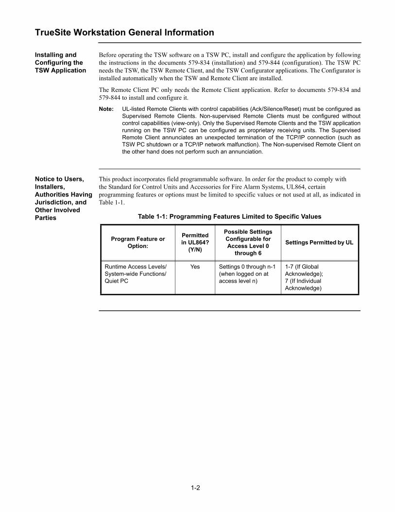
Note: UL-listed Remote Clients with control capabilities (Ack/Silence/Reset) must be configured asSupervised Remote Clients. Non-supervised Remote Clients must be configured withoutcontrol capabilities (view-only). Only the Supervised Remote Clients and the TSW applicationrunning on the TSW PC can be configured as proprietary receiving units. The SupervisedRemote Client annunciates an unexpected termination of the TCP/IP connection (such asTSW PC shutdown or a TCP/IP network malfunction). The Non-supervised Remote Client onthe other hand does not perform such an annunciation.
Notice to Users, Installers, Authorities Having Jurisdiction, and Other Involved Parties
This product incorporates field programmable software. In order for the product to comply withthe Standard for Control Units and Accessories for Fire Alarm Systems, UL864, certainprogramming features or options must be limited to specific values or not used at all, as indicated inTable 1-1.
Table 1-1: Programming Features Limited to Specific Values
Program Feature or Option:
Permitted in UL864?
(Y/N)
Possible Settings Configurable for Access Level 0
through 6
Settings Permitted by UL
Runtime Access Levels/System-wide Functions/Quiet PC
Yes Settings 0 through n-1 (when logged on at access level n)
1-7 (If Global Acknowledge); 7 (If Individual Acknowledge)
1-3
TrueSite Workstation General Information, Continued
Before You Log On (TSW PC)
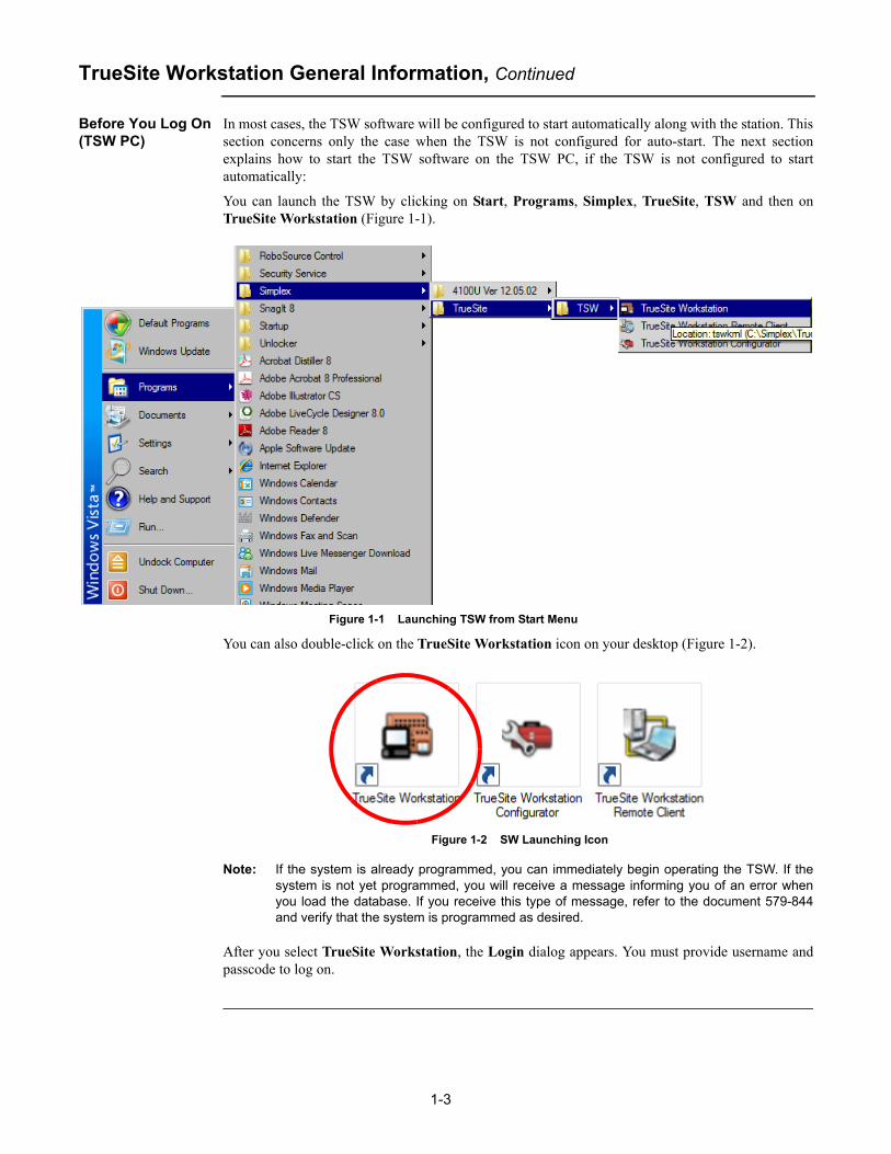
In most cases, the TSW software will be configured to start automatically along with the station. Thissection concerns only the case when the TSW is not configured for auto-start. The next sectionexplains how to start the TSW software on the TSW PC, if the TSW is not configured to startautomatically:
You can launch the TSW by clicking on Start, Programs, Simplex, TrueSite, TSW and then onTrueSite Workstation (Figure 1-1).
Figure 1-1 Launching TSW from Start Menu
You can also double-click on the TrueSite Workstation icon on your desktop (Figure 1-2).
Figure 1-2 SW Launching Icon
Note: If the system is already programmed, you can immediately begin operating the TSW. If thesystem is not yet programmed, you will receive a message informing you of an error whenyou load the database. If you receive this type of message, refer to the document 579-844and verify that the system is programmed as desired.
After you select TrueSite Workstation, the Login dialog appears. You must provide username andpasscode to log on.

1-4
TrueSite Workstation General Information, Continued
Log On (TSW PC) This section is also covered in Chapter 7.
Figure 1-3 Login Dialog Box
To log on:
1. In the Login dialog box (Figure 1-3) provide the following information:
a. Enter your name/number using the digit buttons on the right.
b. Enter your passcode using the digit buttons on the right.
Click on the OK button.

1-5
TrueSite Workstation General Information, Continued
Before You Log On (TSW Remote Client PC)
You can launch the TSW Remote Client by clicking on Start, Programs, Simplex, TrueSite, TSWand then on TrueSite Workstation Remote Client (Figure 1-4).
Figure 1-4 Launching TSW from the Start Menu
You can also double-click on the TrueSite Workstation Remote Client icon on your desktop(Figure 1-5).
Figure 1-5 TSW Launching Icon
Notes: • On the Remote Client PC (where just the Remote Client application is installed), clicking the TrueSite Workstation Remote Client icon launches the Remote Client application.
• If the system is already programmed, you can immediately begin operating the TSW. If the system is not yet programmed, you will receive a message informing you of an error when you load the database. If you receive this type of message, refer to the document 579-844 and verify that the system is programmed as desired.
Refer to Chapter 13 for details on Remote Client types and steps to log on a Remote Clientapplication.


2-1
Chapter 2. TrueSite Workstation Graphical User Interface
Introduction The TSW Graphical User Interface (GUI) allows you to control fire network points and to configureaudiovisual annunciating options. On the TSW PC, the TSW GUI can be launched using the TrueSiteWorkstation icon. On the Remote Client PC, the TSW GUI can be launched with the TrueSiteWorkstation Remote Client icon. This chapter provides listings of all TSW commands available,with an emphasis on describing its interface structure. This section can be used as a reference guidefor specific commands accessible through the GUI. The subsequent chapters will detail the nature ofthese commands.
Note: The TSW GUI can also be referred to as a TSW interface.

2-2
Activating Options
Activating Options You can activate options by using any one of the three methods. You can use a touchscreen, a mouseor a keyboard.
Notes: • If you click on the Help button while activating an option, a pop-up window with information on the particular option you are activating will appear.
• You may also access the Help command by pressing F1 on your keyboard.
Using the Touchscreen to Activate Options
If your system has a touchscreen, you can simply use your finger to press the buttons that appear onthe screen to activate the command.
Caution: There is a thin sensing layer on the surface of the touchscreen. When pressing the screen, be careful not to crease this layer with your fingernail. If this layer is creased, the touchscreen may not function properly.
After pressing the desired button, the commands under that option are made available to you.
Using the Mouse to Activate Options
If your system has a mouse, you can simply click on the button on the screen. After clicking thedesired button, the commands under that option are made available to you.
Using the Keyboard to Activate Options
The TSW is a PC-based product that comes with a keyboard. Use the keyboard to activate options byusing the arrow keys to move to the option of the screen you wish to activate. You can also use theTab button to move forward through the possible options and the Shift +Tab button combination tomove backwards. When the command you wish to activate is selected, press the Enter button. Thecommands under that option are made available to you.
There are also keyboard shortcut keys that can be used to open certain options in the TSW. Thesekeyboard shortcuts appear in the system menubar of the TSW next to the options that they areassociated with. For example: Ctrl + O in the File menu is associated with Open.

2-3
Graphical User Interface
GUI Layout The TSW user interface (Figure 2-1) has a layout composed of the following blocks:
• System wide banner (1)• System menubar (2)• Toolbars (3)• Main window (4)• Major tab area (5)• Minor tab area (6)• System status bar (7)
Figure 2-1 TrueSite Workstation GUI
A maximum of four TSW user interfaces can run simultaneously on a single PC. Each interfacerequires a separate monitor, meaning that a maximum of four monitors can be connected to the PC. Ifonly one monitor is available, it can display both the TSW and TSW Remote Client.
Specify as follows which monitors will be displaying the main TSW window and the TSW RemoteClients:
Monitor for the Main TSW Window
1. Right click on the TrueSite Workstation icon on the desktop and select the Properties option.
2. Select the Shortcut tab and add the argument -screen:X, after -local, inside the “Target” area.The full path now reads ...\TSWDesktop.exe -local -screen:X. Click on the OK button.
Monitor for the TSW Remote Client
1. Right click on the TrueSite Workstation Remote Client icon on the desktop and select the Properties option.
2. Select the Shortcut tab and add the argument -screen:X, after TSWDesktop.exe, inside the“Target” area. The full path now reads ...\TSWDesktop.exe -screen:X. Click on the OK button.
Continued on next page
(1)
(2)
(3)
(4)
(5)
(6)(7)

2-4
Graphical User Interface, Continued
GUI Layout The X represents the screen number which can be determined as follows:
1. Open the Windows Control Panel.
2. Select the Display option.
3. Click on the Settings tab and then on the Identify button (Figure 2-2).
Note: If the screen number entered is invalid, an error message is displayed. By default, the mainTSW window opens on the main monitor.
Figure 2-2 Dialog Box to Identify the Monitors
System Wide Banner
On both the TSW and Remote Client PCs, the system wide banner (Figure 2-3) is visible at the top ofthe screen. It lists the current alarm counts per alarm category. The category buttons will flash whenunacknowledged alarms exist.
Note: The system wide banner is invisible when Remote Client PCs are disconnected from theTSW PC.
Figure 2-3 TrueSite GUI System Wide Banner (with trouble)
2-5
Graphical User Interface, Continued
System Menubar Through the system menubar, five menus are available by default:
• File
• Edit
• View
• Utilities
• Help
The following menus are available when a specific window is selected in the major tab area:
• Fire Panel Network: displays when Network tab is selected
• Graphics: displays when Graphics or Site Info tab is selected
• Operations: displays if Alarm List, Status & Control or Simulator tab is selected
• Report: displays when Report tab is selected
• Historical Log: displays when Historical Log tab is selected
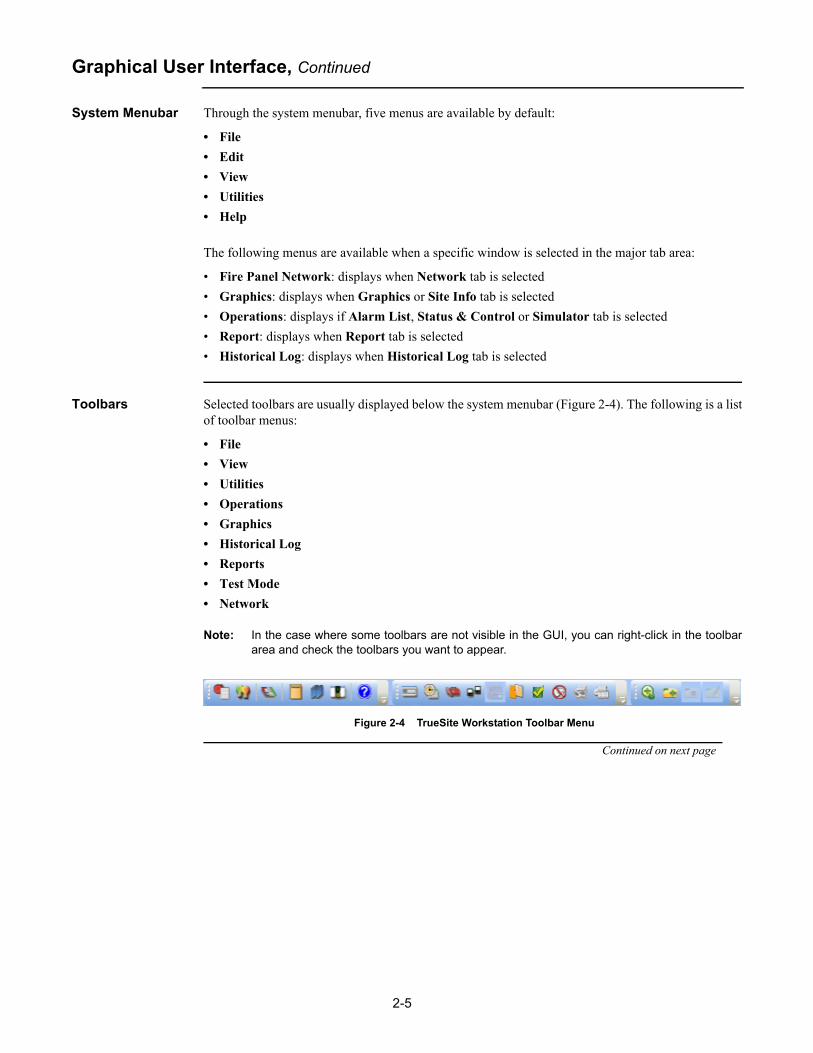
Toolbars Selected toolbars are usually displayed below the system menubar (Figure 2-4). The following is a listof toolbar menus:
• File
• View
• Utilities
• Operations
• Graphics
• Historical Log
• Reports
• Test Mode
• Network
Note: In the case where some toolbars are not visible in the GUI, you can right-click in the toolbararea and check the toolbars you want to appear.
Figure 2-4 TrueSite Workstation Toolbar Menu
Continued on next page

2-6
Graphical User Interface, Continued
Toolbars Table 2-1 lists the available commands under each toolbar menu.
Major Tab Area The major tab area lists all the active tabs and allows you to switch between different views to displayin the main window area.
Note: You can switch between major tabs in the TSW using Ctrl +Tab.
Main Window The main window displays the active screens. This is the area where you can view and select alarmsand points lists to administer the system.
You can set the main window to the following states by right-clicking on any window in the mainwindow area, or selecting a window tab and dragging it with the mouse:
• Floating - When running a multi-monitor setup, floating windows can be moved to other screens. Up to four monitors can be used. Refer to document 579-834 for details on extending your Windows desktop to other available monitors.
One typical use for this feature is to allow you to view the main TSW on the first monitor while the graphics window is fully displayed on a second monitor.
Note: TSW Floating Windows can be maximized by double-clicking on the window title bar.
• Dockable - This enables several docked windows to display simultaneously in the main window area.
• Fixed - Window takes up the entire main window area by default.
• Hidden - Window is not displayed.
Minor Tab Area The minor tab area lists all the available tabs within a specific major tab and allows you to switchbetween different views to display in the main window area.
Note: You can switch between minor tabs in the TSW using Shift +Tab.
Table 2-1: Toolbar Commands List
File Edit View Utilities Operations GraphicsHistorical
LogReport Network
Status(bottom of
screen)
•Open
•Restart
•User Preferences
•Applica-tion Setup
•Connect/Disconnect
•Save Report
•Export XML
•Print Report
•Print Screen
•Exit
•Test Mode
•Alarm Lists
•Points Status & Control
•Graphic Floor Plans
•Reports
•Historical and Operator Logging
•Control Windows
•Login
•Time & Date
•Configurator
•Network
•Site Info
•Point Simulate
•Test Mode
•Quiet Sounder
•Restore All Windows
•Printer Setup
•Printer Control
•Alarm Silence
•System Reset
•Enable/Disable
•Action Message
•View Point Graphic
•Change Status
•Find
•Filter
•Find Next
•Select Loop
•Load Graphics
•Zoom Window
•Pan Window
•Zoom In
•Zoom Out
•Whole Window
•Zoom Previous
•Change View
•Change Volume
•Volume Operation
•Operator Notes
•Find
•Find Next
•Refresh
•Generate
•Terminate
•Clear
•Topology
•Attendance
•Select Loop
•Host Diagnostics
•Prompt Area
•Run-time-Header Area
•Operator Name Area
•Time/Date Area

2-7
Graphical User Interface, Continued
System Status Bar The system status bar is always displayed at the bottom of the main window. It cannot be moved ordocked. The Status Bar will contain the following panes:
• Prompt area (changes based on state of the system)
• Run-time-header (line 1) area – display run-time-header Line 1 (from General Information dataentry in Configurator)
• Run-time-header (line 2) area – display run-time-header Line 2 (from General Information dataentry in Configurator)
• Operator Name area – displays current login/operator
• Time/Date area – displays current time/date:
• The time format is HH:MM:SS. The time is displayed in a 24-hour format.
• The default date format is DAY DD-MON-YY (e.g, TUE 11-APR-06). For Chinese systems, the date format shall is DAY YY-MON-DD.
• The same Time/Date formats are used throughout the TSW.
Sound The TSW PC contains internal speakers that can be used to play different WAV files as alarms occur.The WAV files are custom sound files that can be used as an alternative to standard TSW alarmsounds.
Notes: 1. By default, TSW uses the internal sounder for all sounds. To use WAV files, they must be specified using the TSW Configurator.
2. The TSW Remote Client installed on a Windows 7 (64 bit) PC always uses default WAV files instead of an internal sounder.
If the PC volume has been set to lower than 80%, or if a WAV file is missing or corrupted, the TSWreverts to the PC internal sounder automatically. The TSW continues to use the internal sounder untilthe volume is increased to at least 80% and the TSW application is restarted. A warning dialog is alsoperiodically displayed.
If the volume is below 80% on a Windows 7 (64 bit) Remote Client PC, there is no fallback to theinternal sounder. Instead the original sound continues to play at the lower volume. A single warningmessage is also displayed and once acknowledged, does not re-appear unless the Remote Client isrestarted.
Caution: The TSW PC speakers should not be used for other Windows sound, so as not to interfere with the four TSW WAV file sounds.


3-1
Chapter 3. File Menu
File Menu Commands Summary
The File menu, as shown in Figure 3-1, allows you to perform the following basic commands:
• Opening an existing job
• Restarting the TSW application
• Setting user preferences
• Application setup
• Connect/Disconnect from the TSW (available only on a TSW Remote Client PC)
• Administrator’s Settings (available only on a TSW PC)
• Saving reports
• Exporting to XML
• Printing reports
• Printing the information displayed on the screen
• Emailing event notifications
• Exiting the TSW application
Figure 3-1 File Menu from Menubar and Toolbar Views
File menufrom menubar
File menu from toolbar

3-2
Open
Overview Note: The Open option is not available on a Remote Client PC.
Before you can select a job from a list of available nodes, you must first configure the job and build itusing the TSW Configurator. Refer to document 579-844 for more details.
The Open button (Figure 3-2) allows you to select the active job from a list of available nodes withina specific fire panel network.
Figure 3-2 Open Button
Note: You may also access the Open command by pressing Ctrl + O on your keyboard.
Opening an Existing Job
To open an existing job:
1. Open the File menu. To do so, activate the File toolbar or click on File on the menubar.
2. From the list of commands displayed, Click on Open.
3. From the Job Selection dialog box (Figure 3-3), click on the Select Network button at thebottom left corner.
Figure 3-3 Job Selection Dialog
Continued on next page

3-3
Open, Continued
Opening an Existing Job
4. The Network Selection dialog box appears (as shown in Figure 3-4) with a list of configuredsites. Select the site from which you want to load the job and then click on OK. The NetworkSelection dialog closes.
Figure 3-4 Network Selection Dialog
Note: Selecting a job from a different fire panel network involves an automatic TSW Remote Client application restart prior to the job being loaded. This will disconnect all the Remote Client PCs from the TSW PC. They will need to re-establish connection and download the new job information.
5. After selecting the site, a list of jobs related to the corresponding site appears listed in the JobSelection dialog box, as shown in Figure 3-5.
Figure 3-5 Job Selection Dialog with Loaded Jobs List
6. Select the job you want to load from the Job selection dialog and click on OK.
3-4
Restart
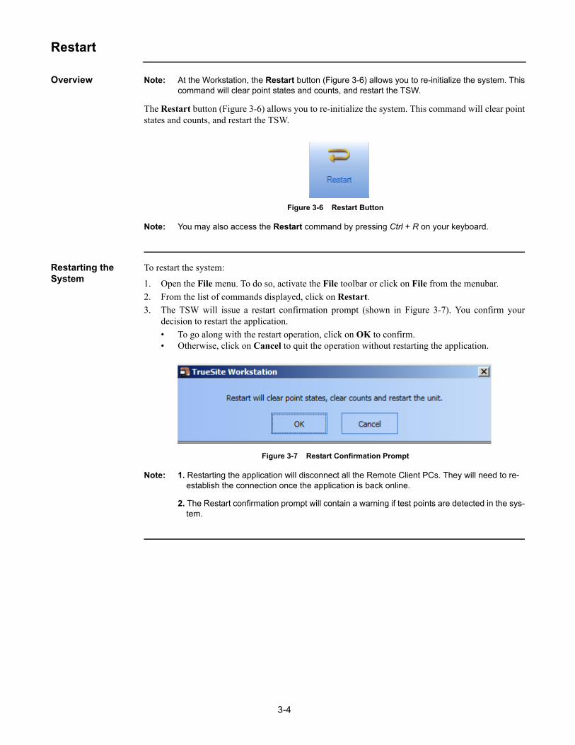
Overview Note: At the Workstation, the Restart button (Figure 3-6) allows you to re-initialize the system. Thiscommand will clear point states and counts, and restart the TSW.
The Restart button (Figure 3-6) allows you to re-initialize the system. This command will clear pointstates and counts, and restart the TSW.
Figure 3-6 Restart Button
Note: You may also access the Restart command by pressing Ctrl + R on your keyboard.
Restarting the System
To restart the system:
1. Open the File menu. To do so, activate the File toolbar or click on File from the menubar.
2. From the list of commands displayed, click on Restart.
3. The TSW will issue a restart confirmation prompt (shown in Figure 3-7). You confirm yourdecision to restart the application.
• To go along with the restart operation, click on OK to confirm. • Otherwise, click on Cancel to quit the operation without restarting the application.
Figure 3-7 Restart Confirmation Prompt
Note: 1. Restarting the application will disconnect all the Remote Client PCs. They will need to re-establish the connection once the application is back online.
2. The Restart confirmation prompt will contain a warning if test points are detected in the sys-tem.

3-5
User Preferences
Overview The User Preferences button (Figure 3-8) allows you to set the TSW display preferences listed inTable 3-1.
Figure 3-8 User Preferences Button
Note: TSW requires the default Windows DPI setting (96 DPI) for both default and large fonts towork properly. See document 579-834 for more details.
Table 3-1: User Preferences Display Options
Settings Options
Font Size Default
Large
Toolbar Size Small
Large
User Interface Theme
MS Office 2003
System
Floating Windows Show Menubar
Show Toolbars
Historical Log View Options
Show Notes Chronologically
Group Notes with Events

3-6
User Preferences, Continued
Accessing the TSW Preferences Dialog Box
To be able to set the display preferences, you must first access the User Preferences dialog box.Follow this procedure:
1. Open the File menu. To do so, activate the File toolbar or click on File from the menubar.
2. From the list of commands displayed, click on User Preferences. A User Preferences dialogbox appears (Figure 3-9). From this point, you may set the display preferences.
Figure 3-9 TSW Preferences Dialog Box
Setting Font Size From the User Preferences dialog box, you may select one of two Font Size options by checking theradio button of the corresponding selection. Figure 3-10 shows the font difference between theDefault and Large options.
Figure 3-10 Default Versus Large Font Size
Note: The Large font setting applies to touchable controls (e.g. buttons, menu items, grid rows,etc.). This option will mostly be used for touchscreen users.
Defaultfonts
Largefonts
3-7
User Preferences, Continued
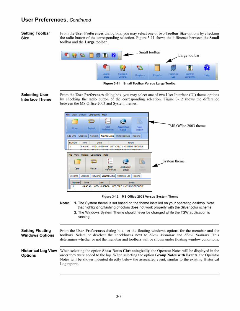
Setting Toolbar Size
From the User Preferences dialog box, you may select one of two Toolbar Size options by checkingthe radio button of the corresponding selection. Figure 3-11 shows the difference between the Smalltoolbar and the Large toolbar.
Figure 3-11 Small Toolbar Versus Large Toolbar
Selecting User Interface Theme
From the User Preferences dialog box, you may select one of two User Interface (UI) theme optionsby checking the radio button of the corresponding selection. Figure 3-12 shows the differencebetween the MS Office 2003 and System themes.
Figure 3-12 MS Office 2003 Versus System Theme
Note: 1. The System theme is set based on the theme installed on your operating desktop. Note that highlighting/flashing of colors does not work properly with the Silver color scheme.
2. The Windows System Theme should never be changed while the TSW application is running.
Setting Floating Windows Options
From the User Preferences dialog box, set the floating windows options for the menubar and thetoolbars. Select or deselect the checkboxes next to Show Menubar and Show Toolbars. Thisdetermines whether or not the menubar and toolbars will be shown under floating window conditions.
Historical Log View Options
When selecting the option Show Notes Chronologically, the Operator Notes will be displayed in theorder they were added to the log. When selecting the option Group Notes with Events, the OperatorNotes will be shown indented directly below the associated event, similar to the existing HistoricalLog reports.
Small toolbarLarge toolbar
MS Office 2003 theme
System theme

3-8
Application Setup
Overview The Application Setup button (Figure 3-13) allows you to select which TCP/IP port the TSWapplication will be using for communication, as well as if other applications are allowed to workwhile the TSW is running. The Application Setup button also allows you to select the type ofRemote Client PC you want to use, the auto-connecting to the TSW PC, and the access to PCMonitoring Setup.
Figure 3-13 Application Setup Button
Accessing the Application Setup Dialog Box
The Application Setup dialog box is different for a TSW on a TSW PC and a Remote Client on aRemote Client PC. The difference is that the TSW Remote Client on a Remote Client PC has toaccess the TSW server remotely, and has to provide connection information as well as the RemoteClient type. To access the Application Setup dialog box, follow this procedure:
1. Click on the File menu, either on the toolbar or on the TSW menubar.
2. From the list of available options, click on Application Setup.
3. The Application Setup dialog box appears. Refer to Figure 3-14 for TSW Client installed on a Remote Client PC. Refer to Figure 3-15 for TSW Client installed on a TSW PC.
Figure 3-14 Application Setup Dialog Box on a Remote Client PC
Continued on next page

3-9
Application Setup, Continued
Accessing the Application Setup Dialog Box
Figure 3-15 Application Setup Dialog Box on a TSW PC
Setting Workstation Identifier
Note: Workstation Identifier box is only available to Remote Clients on Remote Client PCs.
In the Workstation Identifier box, enter the IP address or the computer name of the TSW PC onwhich the TSW application is running.
Setting TCP/IP Port From the Application Setup dialog box (Figure 3-14 or Figure 3-15), you can select the TCP/IP portthat you want the TSW application to use when communicating between TSW and Remote ClientPCs. Port 8831, as shown in Figures 3-15 and 3-14, is entered by default. If needed, another portnumber can be chosen as long as that port is not being used by a service on the TSW or Remote ClientPCs. For instance, ports between 1 and 1023 are reserved for common TCP/IP services and cannot beentered. Verify with the local IT department which computer port can be used prior to replacing thedefault number.
Connection Passcode
Note: Connection Passcode box is only available to Remote Clients on Remote Client PCs.
In the Connection Passcode box, enter the password to connect to the TSW server. Refer to Chapter 3 of document 579-844 for details on where to set the connection passcode.

3-10
Application Setup, Continued
Enable Auto-Connect
Note: 1. The Enable auto-connect button is only available when running a TSW Remote Client.
2. TSW Remote Client can be used to connect to multiple servers from one PC. However, only the last used server name is stored in the User Preferences for use with Auto-Connect
Clicking on this button will test the connection of the Remote Client PC to the TSW PC. If the test issuccessful, the TSW Remote Client will be set to auto-connect on startup. Auto-connect only appliesto TSW startup. It does not apply to File -> Connect.
Remote Client Types
Note: Remote Client Types options are only available to Remote Clients on Remote Client PCs.
For the Remote Client types, you can select either Supervised or Non-supervised Remote Client byclicking on the appropriate radio button. At connection time, the Supervised Remote Client will beprompted to provide a name that will be used to identify it on the TSW application. The Non-Supervised Remote Client will not be asked to provide that name.
Setting the Application Mode
From the Application Setup dialog box, you can set the TSW software as either the only programrunning on the computer (Captive Environment) or allow other programs to run simultaneously(Allow other applications to run). Captive Environment will occupy the entire computer screenand hide the Windows toolbar and task bar.
Note: TSW runs in full-screen mode when Captive Mode is selected on a Windows 7 (64 bit)Remote Client PC. However, it is possible to switch to other applications using buttonsequences (i.e. keyboard accelerators).
Setting the Color Printing
When the Automatically Print Screen or Print Graphics on automatic jump events check box ischecked, a point that enters an alarm state will be displayed on the site graphic in the Graphicswindow. There will also be a printout of the site graphic with that point displayed.
The Color Printing window allows you to choose between three ways of printing the graphics incolor from TSW:
1. No Color Conversion: No color conversion is done.
2. Invert Black and White: Replaces black pixels with white pixels, and vice-versa, before printing.
3. Invert Color: Inverts the color of each pixel before printing. The end result will look like a negative film
Note: In order for Autoprint to work, a default Windows printer must be set. When selected, theAutoprint option will then print to this printer.

3-11
Application Setup, Continued
PC Monitoring Setup
The PC Monitoring Setup button enables you to monitor the overall health of the TSW softwareusing a USB UL card (if no ISA card is installed) on a TSW PC. You can also do the monitoring usingeither a USB UL card or an ISA card on a TSW Remote Client PC. However, if an ISA card isinstalled on a TSW PC, all options on PC Monitoring Setup screen are grayed out.
Notes: 1. The Incident Commander uses only the USB UL card.
2. The Enable ISA Card checkbox and the UL Card Configuration options are unchecked and disabled on a Remote Client installed on a Windows 7 (64 bit) PC.
Refer to the document 579-844: TrueSite Workstation Configurator for instructions on configuring anISA card on a TSW PC. Refer to document 579-834: TrueSite Workstation Installation Manual fordetails on installing the hardware/drivers for an ISA or USB UL I/O card.
Figure 3-16 PC Monitoring Setup Dialog Box
Monitor RAID Activity
When checked, TSW monitors and reports any RAID activity on a PC that has the required RAIDhardware installed.
Notes: 1. The Monitor RAID Activity checkbox is unchecked and disabled on a Remote Client installed on a Windows 7 (64 bit) PC.
2. The TSW software does not monitor RAID activities on a TrueSite Incident Commander PC even if that PC has a working RAID architecture.

3-12
Connect/Disconnect
Overview Note: The Connect/Disconnect button is only available on the Remote Client.
The Connect/Disconnect button (Figure 3-17) displays either Disconnect or Connect, depending onwhether the Remote Client PC is connected or not to the TSW PC. If the Remote Client PC isconnected, the Disconnect button is displayed and clicking it will terminate the connection to theTSW PC. The Connect button is displayed upon first opening the TSW Remote Client software.Clicking it will connect the Remote Client PC to the TSW PC.
Figure 3-17 Connect/Disconnect Button
Accessing the Connect/Disconnect Button
The Connect/Disconnect button is located on the toolbar of the TSW Remote Client application.However, it can also be accessed by opening the File menu and by clicking on the Connect/Disconnect option (Figure 3-18).
Figure 3-18 Connect/Disconnect Menubar and Toolbar Options
Menubar option
Toolbar button
3-13
Administrator’s Settings
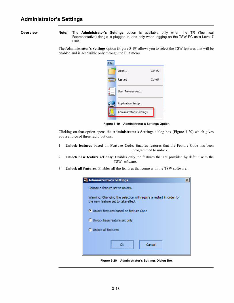
Overview Note: The Administrator’s Settings option is available only when the TR (TechnicalRepresentative) dongle is plugged-in, and only when logging-on the TSW PC as a Level 7user.
The Administrator’s Settings option (Figure 3-19) allows you to select the TSW features that will beenabled and is accessible only through the File menu.
Figure 3-19 Administrator’s Settings Option
Clicking on that option opens the Administrator’s Settings dialog box (Figure 3-20) which givesyou a choice of three radio buttons:
1. Unlock features based on Feature Code: Enables features that the Feature Code has beenprogrammed to unlock.
2. Unlock base feature set only: Enables only the features that are provided by default with theTSW software.
3. Unlock all features: Enables all the features that come with the TSW software.
Figure 3-20 Administrator’s Settings Dialog Box

3-14
Save Report
Overview The Save Report button (Figure 3-21) is used to save the currently displayed report in a file. As such,it is enabled/selectable only when a report has been generated and when the Reports window isactive.
Figure 3-21 Save Report Button
Accessing the Save Report Dialog Box
The Write to File dialog box (Figure 3-22) can be accessed by either clicking on the Save Reportbutton on the toolbar, or by opening the File menu and clicking on Save Report.
Inside the Write to File dialog box, you can select the name for the file and where the report will besaved. Reports are saved in ASCII format.
Figure 3-22 Write to File Dialog Box

3-15
Export XML
Overview The Export XML button (Figure 3-23) is used to export data in the XML format. This button is onlyenabled/selectable when appropriate TSW data is being exported (such as data from inside the AlarmLists, Points Status and Control, Historical Log, Test Mode, or Reports tabs).
Figure 3-23 Export XML Button
Exporting to an XML File
Follow these steps to export data to an XML file:
1. From the File menu, click on the Export XML button, or click on the Export XML button on the File toolbar.
2. In the Export to XML dialog box that opens (Figure 3-24), click on the Browse button to choose a location and a name for the XML file.
3. Click on the Export Now button to export.
Figure 3-24 Export XML Dialog Box

3-16
Print Report
Overview The Print Report button (Figure 3-25) is used to print the currently displayed report on the desiredprinter. Clicking it will bring up the printer selection dialog box. This button will be disabled if theReports tab is not active.
Figure 3-25 Print Report Button
Accessing the Printer Selection Dialog Box
The printer selection dialog box (Figure 3-26) is a standard Windows dialog box for selecting printersconfigured on the computer. It can be accessed by clicking on the Print Report button on the toolbaror by clicking on Print Report in the File menu.
Figure 3-26 Print Dialog Box
Notes: • If the TSW PC is connected to a TCP/IP Network, the TSW will also support printing to the network Windows printers. The network printers cannot be used as supervised printers.
• The network printers presented to the user are from the viewpoint of the invoking PC. This means, for example, that when print commands are issued from a Remote Client, the choices of network printers are those that were set-up on the Remote Client PC at deploy-ment/set-up time. Network printers are not supervised and are not used for event-printing. Consequently, they require no job setup in the Configurator.

3-17
Print Screen
Overview The Print Screen button (Figure 3-27) is used to perform a screen capture of the current screen andprint it on the desired printer.
Figure 3-27 Print Screen Button
The Print Screen button can be found on the toolbar, or as an option inside the File menu. Clicking itwill open the printer selection dialog box (Figure 3-28) from which you can select the printer youwant to print to. The printer selection dialog box is a standard Windows dialog box for selectingprinters configured on the computer.
Figure 3-28 Print Screen Dialog Box
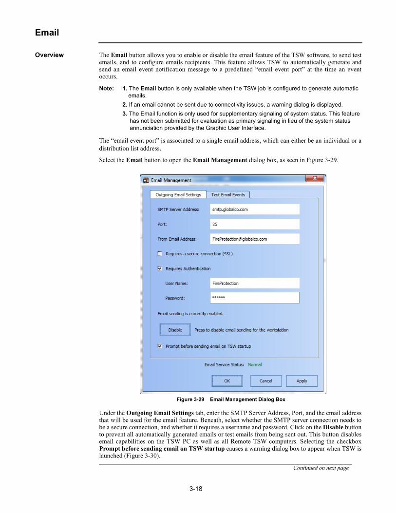
3-18
Overview The Email button allows you to enable or disable the email feature of the TSW software, to send testemails, and to configure emails recipients. This feature allows TSW to automatically generate andsend an email event notification message to a predefined “email event port” at the time an eventoccurs.
Note: 1. The Email button is only available when the TSW job is configured to generate automatic emails.
2. If an email cannot be sent due to connectivity issues, a warning dialog is displayed.
3. The Email function is only used for supplementary signaling of system status. This feature has not been submitted for evaluation as primary signaling in lieu of the system status annunciation provided by the Graphic User Interface.
The “email event port” is associated to a single email address, which can either be an individual or adistribution list address.
Select the Email button to open the Email Management dialog box, as seen in Figure 3-29.
Figure 3-29 Email Management Dialog Box
Under the Outgoing Email Settings tab, enter the SMTP Server Address, Port, and the email addressthat will be used for the email feature. Beneath, select whether the SMTP server connection needs tobe a secure connection, and whether it requires a username and password. Click on the Disable buttonto prevent all automatically generated emails or test emails from being sent out. This button disablesemail capabilities on the TSW PC as well as all Remote TSW computers. Selecting the checkboxPrompt before sending email on TSW startup causes a warning dialog box to appear when TSW islaunched (Figure 3-30).
Continued on next page

3-19
Email, Continued
Overview
Figure 3-30 Email Warning during TSW Startup
Under the Test Email Events tab (Figure 3-31), select the category for which a test email will be sent.Under Specify email recipient(s) for the test, specify the email adress for the test email. Use acomma to separate multiple email addresses. Click on the Send button to send the test email.
Note: When Configured Recipients is selected under Specify email recipient(s) for the test,emails are sent to the recipients specified in a given event category job.
Figure 3-31 Test Email Events Tab

3-20
Email, Continued
Email Account Setup
In order to allow TSW to send emails on event notifications, an SMTP email server must be specified.Contact your Company IT Department to determine the SMTP Server address, port, from-address,and authentication settings (similar to setting up an email client program). If the SMTP server is notreachable over the TCP/IP network, the TSW turns on a system Trouble (P503). Use the Test EmailEvents tab to verify that the TSW emails are sent as expected.
If the user enters an invalid email address, user name or password, the TSW cannot detect the erroruntil an email is sent. It is recommended to send a test email after specifying the Outgoing EmailSettings within TSW, and verify that the email is received by your email program (outside of TSW).
If the outgoing settings are invalid, P503 will turn ON when trying to SEND a test message and it willnot be sent. If the “to-address” is invalid, the SMTP server attempts to send the message andeventually sends an "Message Undeliverable" notice back to the “from account”.
Note: If the TSW PC is running an anti-virus program, you may need to add an exception to allowthe TSW Server process (tswkrnl.exe) to send emails. Refer to your specific anti-virus vendordocumentation for details on how to add exceptions. For McAfee, the process is as follows:
1. Click Start, All Programs, McAfee, and then VirusScan Console.
2. Double-click Access Protection.
3. Select Prevent mass mailing worms from sending mail and click Edit.
4. Add tswkrnl.exe to the list of Excluded Processes.
Important: Ensure that there are no spaces before or after the comma between process names. For example: outlook.exe,msimn.exe.
5. Click OK until the Access Protection Properties window is closed.
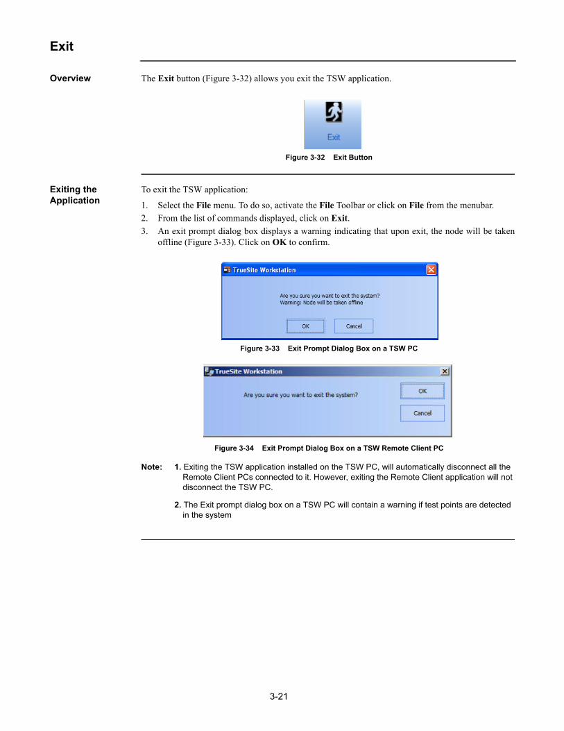
3-21
Exit
Overview The Exit button (Figure 3-32) allows you exit the TSW application.
Figure 3-32 Exit Button
Exiting the Application
To exit the TSW application:
1. Select the File menu. To do so, activate the File Toolbar or click on File from the menubar.
2. From the list of commands displayed, click on Exit.
3. An exit prompt dialog box displays a warning indicating that upon exit, the node will be takenoffline (Figure 3-33). Click on OK to confirm.
Figure 3-33 Exit Prompt Dialog Box on a TSW PC
Figure 3-34 Exit Prompt Dialog Box on a TSW Remote Client PC
Note: 1. Exiting the TSW application installed on the TSW PC, will automatically disconnect all the Remote Client PCs connected to it. However, exiting the Remote Client application will not disconnect the TSW PC.
2. The Exit prompt dialog box on a TSW PC will contain a warning if test points are detected in the system

3-22
Exit, Continued
Exiting the Application (with UL I/O Card)
When exiting the TSW application on a PC containing a UL I/O card, an exit prompt as shown inFigure 3-35 appears. Select the checkbox “Suppress UL I/O card sound and PC Reboot” to preventthe PC from sounding or rebooting.
Note: After TSW exits, do not attempt to immediately shutdown the PC as it can cause the UL I/Ocard to sound. Wait a few seconds and then shut down the PC.
Figure 3-35 Exit Prompt Dialog Box on a PC with a UL I/O Card

4-1
Chapter 4. Edit Menu
Introduction The Edit menu (as shown in Figure 4-1) provides access to the Test Mode submenu, which in turngives access to the following options:
• Add Points
This option allows you to select points to be placed in Test Mode. When you select this option, the Status & Control dialog box appears. You can then drag and drop points from that dialog box and into the Test Mode tab.
• Add Group
This option allows you to add a group of points to be tested to a list of groups in the Test Mode tab. When you select this option, a window prompting you to create a new test group will appear.
• Remove Points
This option allows you to remove any selected points or groups within the Test Mode tab. When points are being taken out of Test Mode, the TSW prompts you to either proceed or cancel to stay in Test Mode.
• Modify Group
This option allows you to change the point provider, the point categories, and the expiration time-out value.
• Save Group
This option allows you to save the group to a file or to disk.
• Restore Group
This option allows you to restore a previously-saved group.
Refer to the section “Test Mode” in Chapter 7 of this document for more details regarding the TestMode feature and the options listed above.
Figure 4-1 The Edit Menu

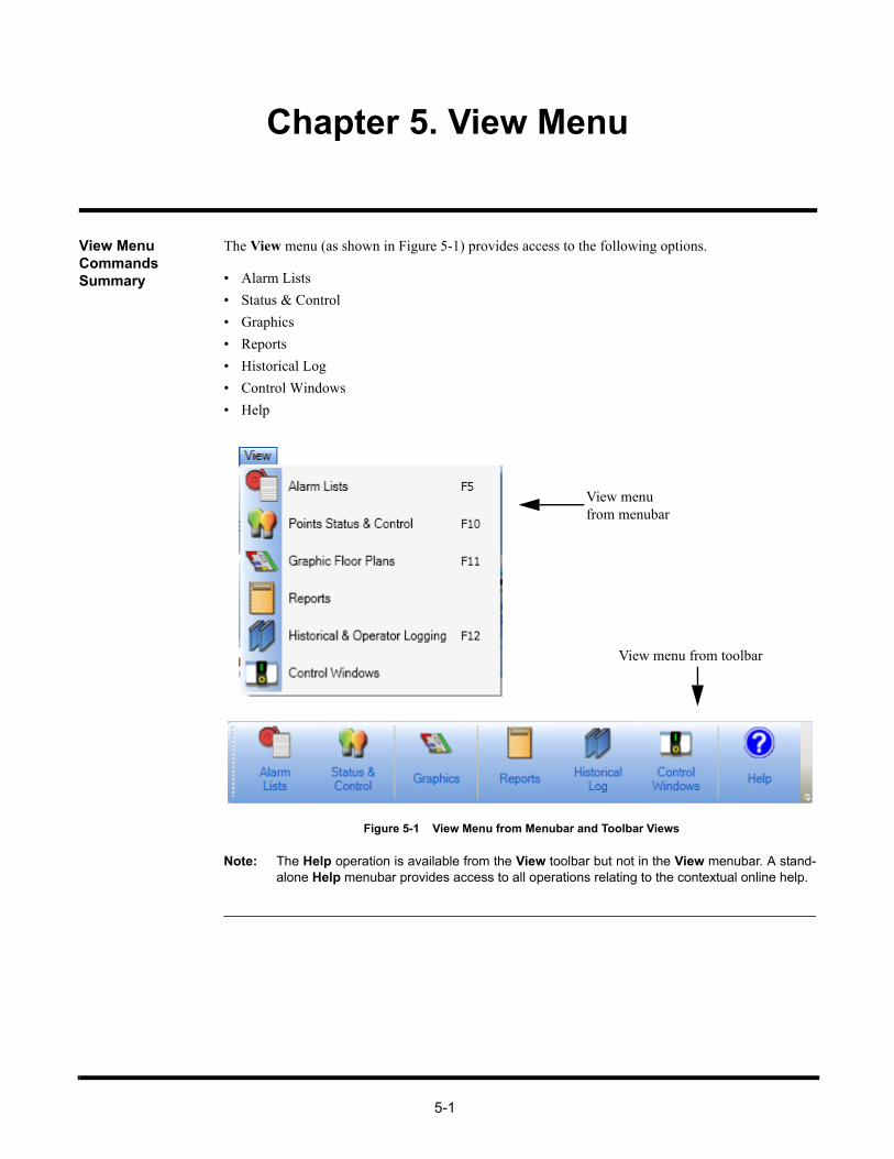
5-1
Chapter 5. View Menu
View Menu Commands Summary
The View menu (as shown in Figure 5-1) provides access to the following options.
• Alarm Lists
• Status & Control
• Graphics
• Reports
• Historical Log
• Control Windows
• Help
Figure 5-1 View Menu from Menubar and Toolbar Views
Note: The Help operation is available from the View toolbar but not in the View menubar. A stand-alone Help menubar provides access to all operations relating to the contextual online help.
View menufrom menubar
View menu from toolbar

5-2
Alarm Lists
Overview The Alarm Lists button (Figure 5-2) allows you to view and acknowledge alarm signals within theAlarm Lists tab. An alarm list displays information that informs the operator when a point changesstates.
Figure 5-2 Alarm Lists Button
Notes: 1. You may also access the Alarm Lists command by pressing F5 on your keyboard or by clicking on Alarm Lists in the View menu.
2. The Operations toolbar menu provides commands relating to the Alarm Lists tab. Refer to Chapter 6 of this document for a description of the operations.
Alarm Lists Window
Figure 5-3 Alarm Lists Tab
Continued on next page

5-3
Alarm Lists, Continued
Alarm Lists Window
From the Alarm Lists tab (Figure 5-3), you can click on the alarm type tabs at the bottom-left of themain window to view the list of current alarms in one of these four types of alarms:
• Fire Alarm
• Priority 2 Alarm
• Supervisory
• Trouble
Notes: 1. For TSW 2.04, “Fire”, “Supervisory”, “Pri2” and "Trouble" Alarm types can display up to 2900 alarms each. By default, all points and alarm categories are vectored to all remote clients.
2. For a Proprietary Supervising Station, only the 4190-8403 is UL-Listed for acknowledging points. The TSW Server GUI is still the only point for acknowledging signals system wide. As a result, Vectored clients are never used for 4190-8403 installations.
The Alarm Lists tab contains the following columns:
• Number - index in the alarm list (oldest first)
• Time - time at which an event has occurred for a specific point (HH:MM:SS)
• Date - date at which an event has occurred for a specific point (WWW DD-MMM-YY)
• Point Name - name of the point in alarm state
• Node Name - name of the node where the point in alarm state is located
• Event - short description of the event
• Detail - point type
• Status - current status of a point
Acknowledging an Alarm
Notes: 1. An active alarm causes the banner to flash and triggers the PC sounder.
2. Press F5 on your keyboard to bring up the list of active alarms. While viewing the alarms list, you can press F5 again to bring up the Acknowledge Box window.
1. From the TSW Remote Client main window, click on the Alarm Lists tab among the selectabletabs.
2. As the list of alarms is displayed, you can browse through the alarm types by selecting theircorresponding tabs at the bottom-left of the main window. Each tab selection displays its own listof alarms.
3. Once you find an unacknowledged (flashing) alarm signal, click on it. An Acknowledge Boxwindow appears as shown in Figure 5-4.
4. From the Acknowledge Box window, you may do the following:
• Acknowledge the alarm
• Add an operator note to the alarm
Note: Accessing the TSW from a TSW PC or a Remote Client PC gives access to the same alarmlist. As such, acknowledging an event on one of the PCs will be reflected on all the other PCson the same TCP/IP network.
Continued on next page

5-4
Alarm Lists, Continued
Acknowledging an Alarm
Figure 5-4 Acknowledge Box Window
5. Click on Acknowledge. The alarm signal goes from flashing to non-flashing in the Alarm Listtab.
6. The alarm remains displayed on the active Alarm List tab for as long as a point is in a non-normal status.
Note: If the system is configured for “Global” acknowledgement of alarms, clicking on theAcknowledge button will acknowledge all of the points in a "Needs Acknowledgement" state.This includes Test Mode points. Even though Test Mode points are not listed in the AlarmList window, “Global” settings must match for all nodes on the 4120 Network. This operationwill affect Test Mode points as well. As a result, when these points are removed from TestMode, the point states will appear as acknowledged. If the system is configured for “GroupAcknowledgement”, only points in a specific group are acknowledged.
Adding Operator Notes
To add an operator note, follow this procedure:
1. Follow steps 1 to 4 from the “Acknowledging an Alarm” section.2. From the Acknowledge Box window, click on Operator Notes. 3. An Add Operator Note dialog box appears, as shown in Figure 5-5.4. In the text field, compose a note you would like to include for the point.
Figure 5-5 Add Operator Note Dialog
5. Once you have finished composing the note in the text field, click on Save to add the note.
Note: When a note is added from the Acknowledge box, it is automatically associated with theevent displayed in the Acknowledge box.

5-5
Status & Control
Overview The Status & Control button (Figure 5-6) allows you to access the Status & Control tab whichcontains a scrollable list of entries to all points in the system. From this window, you can view thestatus of points within the fire network and configure their settings.
Figure 5-6 Status & Control Button
Note: You may also access the Status & Control command by pressing F10 on your keyboard orby clicking on Point Status & Control in the View menu.
Status & Control Window
Note: When the Status & Control tab (Figure 5-7) is selected in the main window area, theOperations toolbar menu automatically becomes available.The TSW allows you to turn on/off a filter row for typing in textual filters for one or multiple columns. To activate the filter, click on the icon on the top right corner of the main window.
Figure 5-7 Point Status & Control Window
Continued on next page

5-6
Status & Control, Continued
Status & Control Window
The Status & Control grid (as seen in Figure 5-7) contains the following columns:
• Point Name - unique identifier that is specific to a point.
• Point Indicator - The icon in that column indicates that a point is currently in test mode.
The icon indicates that the point is in simulation mode.
The indicates that the point is in Install Mode. When a point is in InstallMode, it does not appear on any TSW active lists and can be taken out of InstallMode at the panel only.
Note: Point P511 is turned on to indicate that a point has been placed inInstall Mode.
• Node Name - unique identifier that is specific to a node which contains the specific point.
• Description - a short description of a point.
• Point Type - type of point
• Status - status that changes only for each point
Note: When a DACR point exists, the following additional information is also displayed:
• Acct
• Group
• CID Number
Point & Status Window Operations
The Operations toolbar menu provides commands relating to the Status & Control tab. Refer toChapter 6 of this document for a description of the following available operations:
• Displaying the status of a point
• Changing the status of a point
• Silencing an alarm
• Resetting the system
• Finding a point
• Filtering the current list of points
• Viewing the point graphic
• Adding operator’s notes for a point
• Viewing operator’s notes for a point
• Viewing action messages associated with a point

5-7
Control Windows
Overview The Control Windows button (Figure 5-8) activates the Control Windows tab. The ControlWindows tab can also be activated by clicking on Control Windows in the View menu.
Figure 5-8 Control Windows Button
The Control Windows main screen (Figure 5-9) contains five tabbed windows in the bottom left-hand corner: Utility, Phone, Standard audio, Auxiliary audio and Speaker audio. It also displayscustom control created by the operator using the TSW Configurator.
Note: The Control Windows tab on a Supervised Remote Client PC only shows rows that arelinked to points that are visible to that client.
Figure 5-9 Control Windows Tab
When the Control Windows major tab is selected, five options are available in the minor tab:
• Utility• Phone (only available on the TSW PC)• Standard audio• Auxiliary audio• Speaker audio

5-8
Control Windows, Continued
Utility The Utility minor tab window (Figure 5-10) contains a dropdown box that lists all utility controlscreens defined for the current job. Each row displayed contains a point label. Next to each label is aseries of one or more buttons that can be used to perform control operations on a specified point.
Figure 5-10 Utility Minor Tab
To perform a control operation on a point:
1. Click on a utility control screen from the dropdown list.
2. A grid containing point labels and control buttons appears.
3. Click on the appropriate button of the lower tab to perform the desired operation on a specified point.

5-9
Control Windows, Continued
Phone Note: This option is available only on the TSW PC. It is grayed-out on the Remote Client PC.
The Phone minor tab window displays rows of phone circuit representing incoming calls on remotephones. Each row contains a phone circuit label. Next to each label are two color-coded buttons:
• ANSWER
• HOLD
Additionally, two general command buttons are available at the top of the grid. These operationsaffect all phones.
• Answer All
• Call Out
Standard Audio The Standard audio minor tab window (Figure 5-11) displays an empty grid by default. The buttonsdisplayed depend on the audio type and the number of channels:
• MANUAL AUDIO EVACUATION (OFF, ON)
• EVACUATION MESSAGE (OFF, ON)
• LOCAL SPEAKER (OFF, ON EVAC)
• ALL SPEAKERS TALK (OFF, ON)
Figure 5-11 Standard Audio Minor Tab

5-10
Control Windows, Continued
Auxiliary Audio and Speaker Audio
The Auxiliary audio and Speaker audio minor tabs (Figures 5-12 and 5-13 respectively) display therows that contain point labels. Next to each label is a series of one or more buttons that can be used toperform control operations on a specified point. The buttons depend on the mode used to create theaudio control screen entries and are color-coded.
Figure 5-12 Auxiliary Audio Minor Tab
Continued on next page

5-11
Control Windows, Continued
Auxiliary Audio and Speaker Audio
Figure 5-13 Speaker Audio Minor Tab

5-12
Graphics
Overview The Graphics button (Figure 5-14) allows you to view a graphical floor plan for the site, through theGraphics tab, if an initial graphic screen is specified for the job. Otherwise, the Graphics tab isdisplayed blank.
Figure 5-14 Graphics Button
Notes: 1. Graphics are operator-defined and are programmable using the TSW Configurator. Refer to publication 579-844 for details on how to program graphics into a TSW job.
2. You may also access the Graphics command by pressing F11 on your keyboard or by clicking on Graphic Floor Plans in the View menu.
Figure 5-15 An Operator-defined Graphics Window
After panning andzooming in
Normal View

5-13
Graphics, Continued
Graphics Menu Options
The Graphics menu allows you to control the visual display of the Graphics tab. As shown inFigure 5-16, the following operations are available from this menu:
• Load Graphics
• Zoom Window
• Pan Window
• Zoom In
• Zoom Out
• Whole Window
• Zoom Previous
Figure 5-16 Graphics Menu from Menubar and Toolbar Views
Notes: 1. To be able to access the Graphics toolbar menu, you must first activate it as follows: Right-click on the toolbar portion of the TSW interface. From the list of available toolbar menus, select Graphics Toolbar. The Graphics menu should be displayed on the toolbar.
2. The TSW activates the Graphics toolbar menu whenever the Graphics window is active in the main window area.
3. If the “Block Pan and Zoom Operations at Runtime” checkbox in the Document Attributes dialog box of the TSW Configurator is checked, all buttons of the Graphics toolbar, except Load Graphic and Print, will be grayed-out.
Graphics menufrom menubar
Graphics menu from toolbar

5-14
Graphics, Continued
Load Graphics The Load Graphics button (Figure 5-17) opens the Load Graphic dialog box from which you canselect a graphic to open.
Figure 5-17 Load Graphics Button
Zoom Window Notes: 1. Either Zoom Window or Pan Window is always selected (not both). The selected option is highlighted/selected in the menubar/toolbar.
2. You may also use Ctrl + (arrow keys) on your keyboard to zoom in and out.
Figure 5-18 Zoom Window Button
The Zoom Window button (Figure 5-18) allows you to select a zoom area in the Graphics tab. To doso, follow this procedure:
1. Click on Zoom Window in the Graphics toolbar menu.
2. Using your mouse, place the pointer over the area of the Graphics tab you want to view. Then,left-click and drag.
The area you selected becomes the zoom area.
Pan Window Notes: 1. Either Zoom Window or Pan Window is always selected (not both). The selected option is highlighted/selected in the menubar/toolbar.
2. You may also Pan in a Graphics screen by pressing the arrow keys (up, down, left or right) on your keyboard.
Figure 5-19 Pan Window Button
The Pan Window button (Figure 5-19) allows you to move along any direction in the Graphics tab.To do so, follow this procedure:
1. Click on the Pan Window button in the Graphics toolbar menu.
2. Using your mouse, place the pointer and left-click any area of the Graphics tab.
3. Hold the mouse button and drag along any direction to pan the window. You should be able tomove the screen around to show different parts of the Graphics tab.
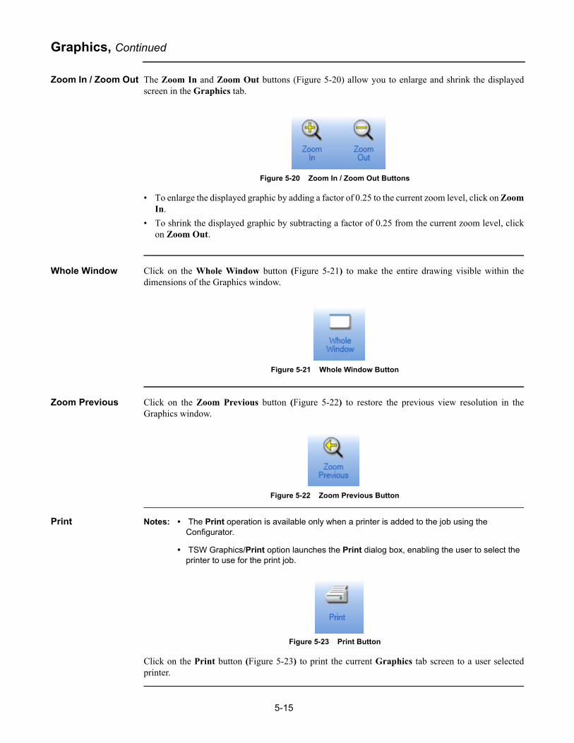
5-15
Graphics, Continued
Zoom In / Zoom Out The Zoom In and Zoom Out buttons (Figure 5-20) allow you to enlarge and shrink the displayedscreen in the Graphics tab.
Figure 5-20 Zoom In / Zoom Out Buttons
• To enlarge the displayed graphic by adding a factor of 0.25 to the current zoom level, click on ZoomIn.
• To shrink the displayed graphic by subtracting a factor of 0.25 from the current zoom level, clickon Zoom Out.
Whole Window Click on the Whole Window button (Figure 5-21) to make the entire drawing visible within thedimensions of the Graphics window.
Figure 5-21 Whole Window Button
Zoom Previous Click on the Zoom Previous button (Figure 5-22) to restore the previous view resolution in theGraphics window.
Figure 5-22 Zoom Previous Button
Print Notes: • The Print operation is available only when a printer is added to the job using the Configurator.
• TSW Graphics/Print option launches the Print dialog box, enabling the user to select the printer to use for the print job.
Figure 5-23 Print Button
Click on the Print button (Figure 5-23) to print the current Graphics tab screen to a user selectedprinter.

5-16
Reports
Overview The Report button (Figure 5-24) activates the Reports tab (Figure 5-25). You can also access theReports tab by clicking on Reports in the View menu.
Figure 5-24 Report Button
Figure 5-25 Reports Window
Note: The Reports toolbar menu provides commands relating to the Reports tab. Refer to Chapter10 of this document for details on the Reports toolbar and menu.

5-17
Historical Log
Overview The Historical Log button (Figure 5-26) activates the Historical Log tab (Figure 5-27). You mayalso access the Historical Log tab by pressing F12 on your keyboard or by clicking on Historical &Operator Logging under the View menu.
Figure 5-26 Historical Log Button
Figure 5-27 Historical Log Window
Note: The Historical Log tab on a Supervised Remote Client PC only shows the events for pointsthat are vectored to that Remote Client.
The Historical Log toolbar menu provides the following commands relating to the Alarm Lists tab.Refer to Chapter 9 of this document for details on the Historical Log toolbar menu.
• Change View• Change Volume• Volume Operation• Refresh• Operator Notes• Find• Find Next

5-18
Help
Overview The Help button (Figure 5-28) activates the Help window (Figure 5-29).
Figure 5-28 Help Button
Note: You can press F1 to access a help file relating to any context within the TSW application.
Figure 5-29 Help Window
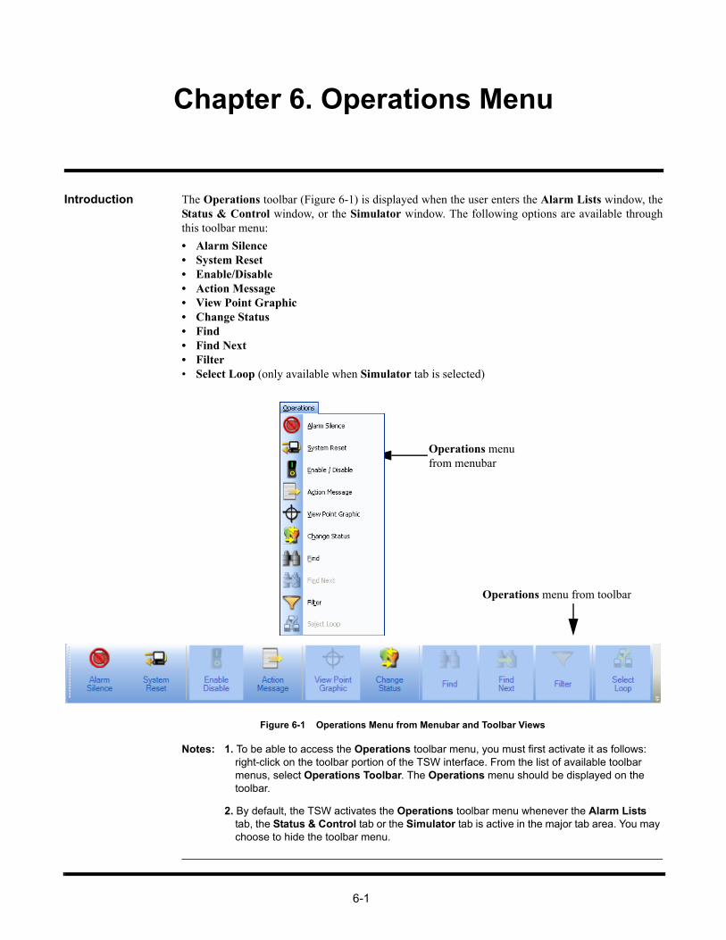
6-1
Chapter 6. Operations Menu
Introduction The Operations toolbar (Figure 6-1) is displayed when the user enters the Alarm Lists window, theStatus & Control window, or the Simulator window. The following options are available throughthis toolbar menu:
• Alarm Silence• System Reset• Enable/Disable• Action Message• View Point Graphic• Change Status• Find• Find Next• Filter• Select Loop (only available when Simulator tab is selected)
Figure 6-1 Operations Menu from Menubar and Toolbar Views
Notes: 1. To be able to access the Operations toolbar menu, you must first activate it as follows: right-click on the toolbar portion of the TSW interface. From the list of available toolbar menus, select Operations Toolbar. The Operations menu should be displayed on the toolbar.
2. By default, the TSW activates the Operations toolbar menu whenever the Alarm Lists tab, the Status & Control tab or the Simulator tab is active in the major tab area. You may choose to hide the toolbar menu.
Operations menufrom menubar
Operations menu from toolbar

6-2
Alarm Silence
Overview The Alarm Silence button (Figure 6-2) allows you to silence an active alarm signal. The AlarmSilence button can also be accessed by clicking on the Operations menu.
Figure 6-2 Alarm Silence Button
Note: In order to use the Alarm Silence option, the proper list must first be populated using theConfigurator.
Silence an Alarm Note: If there is an active alarm in the system, the banner flashes and the PC sounder is triggered,if configured.
To send an Alarm Silence command over the fire network, follow this procedure:
1. Click on Alarm Silence in the Operations menu.
2. An Alarm Silence confirmation dialog box appears as shown in Figure 6-3. Click on AlarmSilence in the confirmation dialog box.
Figure 6-3 Alarm Silence Confirmation Dialog
The message “ALARM SILENCE IN PROGRESS” will be displayed in the status bar at the bottom ofthe screen. After a few seconds, the status message disappears. The alarm is silenced at all configuredfire network nodes.
Note: “Silence” will be indicated in the system status bar until the system resets or until a resoundoccurs.

6-3
System Reset
Overview The System Reset button (Figure 6-4) allows you to reset the system. The System Reset button canalso be accessed by clicking on the Operations menu.
Figure 6-4 System Reset Button
Note: In order to use the System Reset option, the proper list must first be populated using theConfigurator.
Reset the System Note: You must activate either the Alarm List window or the Status & Control window in order toreset the system.
To send a System Reset command over the network, follow this procedure:
1. Click on System Reset in the Operations menu.
2. A System Reset confirmation dialog box appears as shown in Figure 6-5.
Figure 6-5 System Reset Confirmation Dialog Box
Clicking on Priority 2 Reset button resets only the Priority 2 alarms
Clicking on System Reset resets all the troubles and alarms, except Priority 2 alarms.
Note: The progress of the system reset is indicated in the system status bar.

6-4
Enable/Disable
Overview The Enable/Disable button (Figure 6-6) allows you to enable and disable a point in the TSW. TheEnable/Disable button can also be accessed by clicking on the Operations menu.
Figure 6-6 Enable/Disable Button
Note: The Alarm List or the Status & Control tab needs to be selected in the major tab area toenable the Enable/Disable button.
Enable a Point To enable a point, follow this procedure:
1. Select a point from the Alarm List or the Status and Control tabs.
2. After selecting the point, click on Enable/Disable in the Operations menu.
3. An Enable/Disable Point dialog box appears. Click Enable.
4. The Enable Operation dialog box appears. This dialog box displays a dynamic text control thatreads“Point will be ENABLED in x seconds” from 60 down to 0 seconds.
5. You may choose between the following courses of action:
• Wait for the countdown to end.
• Click on the Enable Immediate button to terminate the countdown.
Note: After step 5, the Enable Operation dialog box disappears. You will be unable to cancel theoperation.
The enable point command is then sent to the panel and the dialog box closes.
Disable a Point To disable a point, follow this procedure:
1. Select a point from the Alarm List or Status & Control tabs.
2. After selecting the point, click on Enable/Disable in the Operations menu.
3. Click on the Disable TROUBLE button
The disable point command is sent to the fire network and the dialog box closes. A trouble conditionis then created.

6-5
Action Message
Overview The Action Message button (Figure 6-7) allows you to open and view point information from theAction Message tab in the Status & Control dialog box. The Action Message button can also beaccessed by clicking on the Operations menu.
Figure 6-7 Action Message Button
View Action Message
Note: You must activate either the Active List tab or the Status & Control tab in order to use theAction Message button.
To view action message information, follow this procedure:
1. Select an active alarm from the Alarm List window or an active point from the Status &Control window.
2. After making your selection, click on Action Message in the Operations menu.
The Status & Control dialog box activated under Action Message tab appears as shown in Figure 6-8. The following information is displayed:
• Node Name
• Custom Label
• Point Name
• Point Type
• DACR account - Group - CID Number
Figure 6-8 Status & Control Dialog Box, Action Message Tab
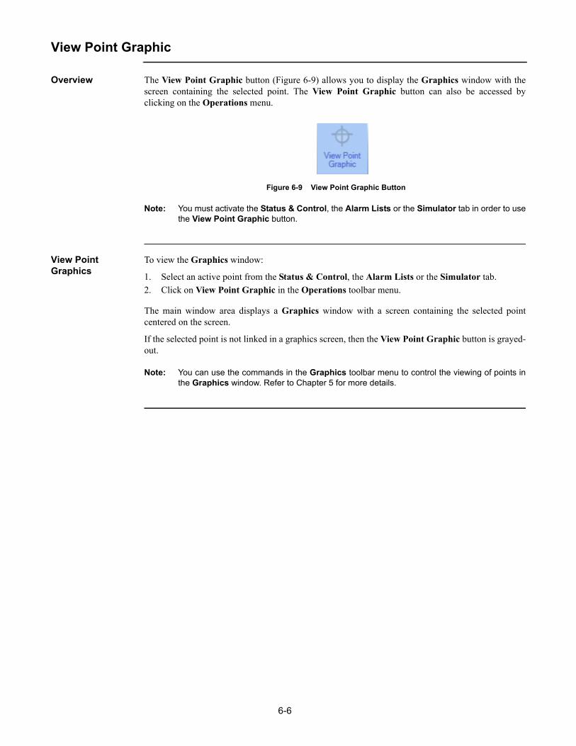
6-6
View Point Graphic
Overview The View Point Graphic button (Figure 6-9) allows you to display the Graphics window with thescreen containing the selected point. The View Point Graphic button can also be accessed byclicking on the Operations menu.
Figure 6-9 View Point Graphic Button
Note: You must activate the Status & Control, the Alarm Lists or the Simulator tab in order to usethe View Point Graphic button.
View Point Graphics
To view the Graphics window:
1. Select an active point from the Status & Control, the Alarm Lists or the Simulator tab.
2. Click on View Point Graphic in the Operations toolbar menu.
The main window area displays a Graphics window with a screen containing the selected pointcentered on the screen.
If the selected point is not linked in a graphics screen, then the View Point Graphic button is grayed-out.
Note: You can use the commands in the Graphics toolbar menu to control the viewing of points inthe Graphics window. Refer to Chapter 5 for more details.

6-7
Change Status
Overview The Change Status button (Figure 6-10) allows you to change the status of a point. It will launch theStatus & Control dialog box for the selected point. The Change Status button can also be accessedby clicking on the Operations menu.
Figure 6-10 Change Status Button
Note: The Change Status button is only available when the Status & Control, Alarm List orSimulator tabs are selected in the major tab area.
Change Point Status
To change the status of a point, follow this procedure:
1. Select a point from the Status & Control, the Alarm Lists or the Simulator tab.
2. Click on Change Status in the Operations toolbar menu.
A Status & Control dialog box appears with the Status & Control tab selected. If the point is in TestMode, a modified Status & Control dialog box will appear, indicating the point is in Test Mode. Theline IN INSTALL MODE appears below the point information area if the point is in Install Mode.
Note: You can also access the Status and Control dialog box by double-clicking on a point. Fordifferent points, different control operations will be available.
Figure 6-11 Status & Control Dialog, Control Tab
3. Set a new status by clicking on one of the available state selection categories. In this example, asystem Pseudo Point is used:
• To set a point status to Normal, click on Normal NORMAL.
• To set a point status to Abnormal, click on Abnormal TROUBLE.
4. To set a new point priority number, click on the Increase Priority and Decrease Priority buttonson the right to increase and decrease the priority respectively.
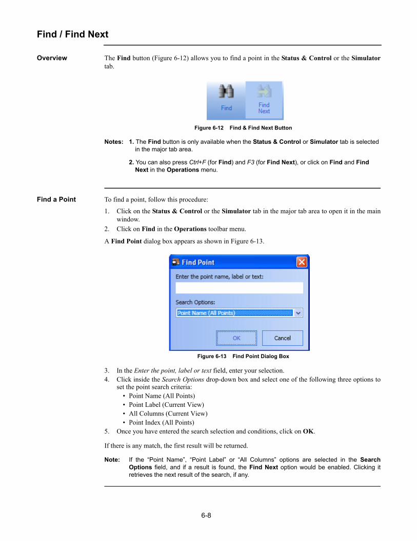
6-8
Find / Find Next
Overview The Find button (Figure 6-12) allows you to find a point in the Status & Control or the Simulatortab.
Figure 6-12 Find & Find Next Button
Notes: 1. The Find button is only available when the Status & Control or Simulator tab is selected in the major tab area.
2. You can also press Ctrl+F (for Find) and F3 (for Find Next), or click on Find and Find Next in the Operations menu.
Find a Point To find a point, follow this procedure:
1. Click on the Status & Control or the Simulator tab in the major tab area to open it in the mainwindow.
2. Click on Find in the Operations toolbar menu.
A Find Point dialog box appears as shown in Figure 6-13.
Figure 6-13 Find Point Dialog Box
3. In the Enter the point, label or text field, enter your selection.4. Click inside the Search Options drop-down box and select one of the following three options to
set the point search criteria:• Point Name (All Points)• Point Label (Current View)• All Columns (Current View)• Point Index (All Points)
5. Once you have entered the search selection and conditions, click on OK.
If there is any match, the first result will be returned.
Note: If the “Point Name”, “Point Label” or “All Columns” options are selected in the SearchOptions field, and if a result is found, the Find Next option would be enabled. Clicking itretrieves the next result of the search, if any.

6-9
Filter
Overview The Filter button (Figure 6-14) allows you to filter the display of the point list in the Status &Control tab. The Filter button can also be accessed by clicking on the Operations menu.
Figure 6-14 Filter Button
Note: The Filter button is only available when the Status & Control or Simulator tab is selected inthe major tab area.
Filter Points To filter points displayed in the Status & Control tab, follow this procedure:
1. Click on the Status & Control or Simulator tab in the major tab area to open it in the mainwindow.
2. Click on Filter in the Operations toolbar menu.
A Point Filter dialog box appears, as shown in Figure 6-15.
Figure 6-15 Point Filter Dialog Box
3. Under the Point Category list, you can check or un-check any of the following checkboxes todisplay or filter the corresponding content:
• Monitor
• Control
• Analog Pseudo
• Digital Pseudo
• List Pseudo
• Common Trouble
• Other
Notes: 1. To check the entire list of options, click on Select All.
2. To uncheck the entire list of options, click on Clear All.
4. Click on OK to confirm selections.
The Status & Control and Simulator tab will be updated to filter out unselected categories.
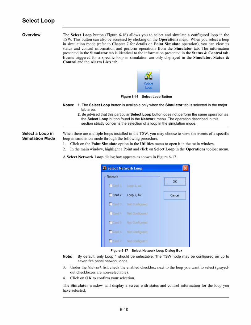
6-10
Select Loop
Overview The Select Loop button (Figure 6-16) allows you to select and simulate a configured loop in theTSW. This button can also be accessed by clicking on the Operations menu. When you select a loopin simulation mode (refer to Chapter 7 for details on Point Simulate operation), you can view itsstatus and control information and perform operations from the Simulator tab. The informationpresented in the Simulator tab is identical to the information presented in the Status & Control tab.Events triggered for a specific loop in simulation are only displayed in the Simulator, Status &Control and the Alarm Lists tab.
Figure 6-16 Select Loop Button
Notes: 1. The Select Loop button is available only when the Simulator tab is selected in the major tab area.
2. Be advised that this particular Select Loop button does not perform the same operation as the Select Loop button found in the Network menu. The operation described in this section strictly concerns the selection of a loop in the simulation mode.
Select a Loop in Simulation Mode
When there are multiple loops installed in the TSW, you may choose to view the events of a specificloop in simulation mode through the following procedure:1. Click on the Point Simulate option in the Utilities menu to open it in the main window.2. In the main window, highlight a Point and click on Select Loop in the Operations toolbar menu.
A Select Network Loop dialog box appears as shown in Figure 6-17.
Figure 6-17 Select Network Loop Dialog Box
Note: By default, only Loop 1 should be selectable. The TSW node may be configured on up toseven fire panel network loops.
3. Under the Network list, check the enabled checkbox next to the loop you want to select (grayed-out checkboxes are non-selectable).
4. Click on OK to confirm your selection.
The Simulator window will display a screen with status and control information for the loop youhave selected.
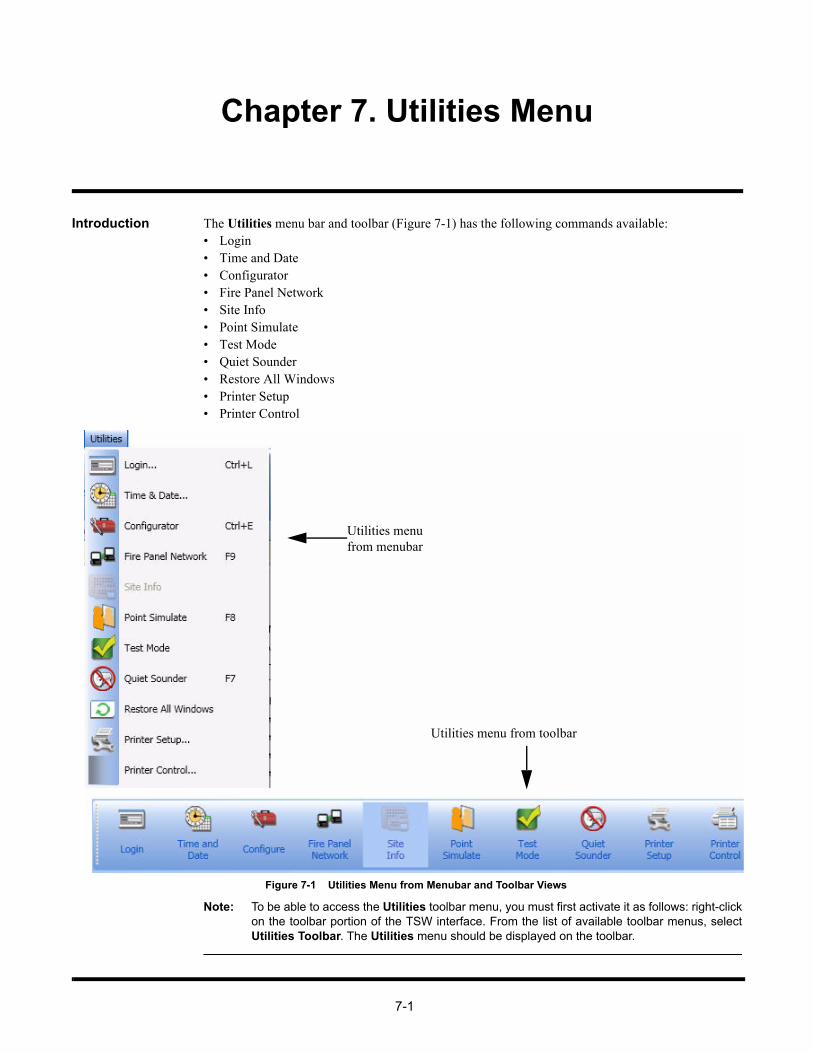
7-1
Chapter 7. Utilities Menu
Introduction The Utilities menu bar and toolbar (Figure 7-1) has the following commands available:• Login• Time and Date• Configurator• Fire Panel Network• Site Info• Point Simulate• Test Mode• Quiet Sounder• Restore All Windows• Printer Setup• Printer Control
Figure 7-1 Utilities Menu from Menubar and Toolbar Views
Note: To be able to access the Utilities toolbar menu, you must first activate it as follows: right-clickon the toolbar portion of the TSW interface. From the list of available toolbar menus, selectUtilities Toolbar. The Utilities menu should be displayed on the toolbar.
Utilities menufrom menubar
Utilities menu from toolbar

7-2
Login
Overview The Login button (Figure 7-2) allows you to log-on to the TSW system. You can also change yourexisting passcode through the Login or Log Off dialog box.
Note: If you wait too long to login and the TR message is displayed, the Login dialog box does notappear.
Figure 7-2 Login Button
Log on to TSW To log in, follow this procedure:
1. Click on Login in the Utilities menu. The Login dialog box appears, as shown in Figure 7-3.
Figure 7-3 Login Dialog Box
2. In the Login dialog box, provide the following information:
a. Enter your name/number using the digit buttons on the right or using the keyboard.
b. Enter your secret passcode using the digit buttons on the right or using the keyboard.
3. Click OK.
Notes: • After you have successfully logged onto the TSW, the operator fields will be filled with the appropriate information.
• You may also access the Login command by pressing Ctrl + L on your keyboard.

7-3
Login, Continued
Log Off To log off from the TSW:
1. While you are logged in, click on Login in the Utilities toolbar. The Login dialog box appears,as shown in Figure 7-4.
Figure 7-4 Login Dialog Box, Log Off
2. In the Login dialog box, click on Log Off.
Note: If the system is configured with an inactivity timeout, the system automatically logs off after agiven expiration time period (default is 30 minutes).
Change Passcode To change your passcode:
1. Click on Login in the Utilities toolbar. The Login dialog box appears.
2. In the Login dialog box, click Change Passcode. A Change Passcode dialog box (Figure 7-5)prompts you to change your passcode.
Figure 7-5 Passcode Change Dialog Box
3. You must provide your current passcode and then enter the new passcode twice for validation.
4. Once you have provided this information, click on OK.
The passcode is changed.

7-4
Time and Date
Overview The Time & Date button (Figure 7-6) allows you to change the time and date in the system.
Figure 7-6 Time and Date Button
Set the Time and Date
1. From the Utilities toolbar menu, click on Time and Date.
2. The Time and Date dialog box appears as shown in Figure 7-7. In this dialog box, you maychange time and date settings as follows:
• To change the time, click on the spinner up/down arrows to increment or decrement the time value until the correct time value is displayed in the time field.
• To change the date, select the dropdown button to view the calendar and click on a date. The selected date will be displayed in the date field.
3. After making changes to the time and date, the following options are available:
• Click on OK to confirm time and date changes and to close the Time and Date dialog box.
• Click on Apply to confirm time and date changes without closing the Time and Date dialog box.
• Click on Close to dismiss the Time and Date dialog box.
Figure 7-7 Time and Date Dialog
Note: When the TSW Configurator option Set Time/Date also Updates Supervised RemoteClient is enabled, changing the time/date on a TSW or a Supervised Remote Client PCautomatically changes it on all connected PCs, except for the Non-Supervised Remote ClientPCs. A time/date update is also sent to all supervised Remote Clients at noon and midnightevery day.

7-5
Configure
Overview Note: This option is only available on the TSW PC.
The Configure button (Figure 7-8) allows you to launch the TSW Configurator. You can also usethe Configurator option from the Utilities menu.
Figure 7-8 Configure Button
Note: The Configure button (or Configurator option if using the Utilities menu) can only be usedfor limited functions when invoked from the TSW application. In order to use the fullfunctioning Configurator, you must exit the TSW application and manually launch theConfigurator.
Launch the Configurator
From the Utilities toolbar menu, click on Configurator. The TSW Configurator launches with thecurrent job as shown in Figure 7-9.
Note: You may also access the Configure command by pressing Ctrl + E on your keyboard, or byclicking on the Configurator button in the Utilities menu.
Figure 7-9 TSW Configurator

7-6
Fire Panel Network
Overview The Fire Panel Network button (Figure 7-10) allows you to launch the Network tab.
Figure 7-10 Fire Panel Network Button
Notes: 1. You may also access the Network tab by pressing F9 on your keyboard, or by clicking on Fire Panel Network inside the Utilities menu.
2. Refer to Chapter 11 of this document for details on Network tab operations.

7-7
Site Info
Overview The Site Info button (Figure 7-11) allows you to view the Site Info and Graphics tab. There are threepossible configurations:
• No configuration
• Configured for a graphic screen
• Configured for action messages 100-105
Figure 7-11 Site Info Button
Note: If both Graphics screen and Action Messages are configured, the Site Info tab will displaythe Graphics screen.
Option: No Configuration
If no graphic screen and action messages are configured, the Site Info button will be disabled(grayed-out).
Option: Configured for a Graphic Screen
Notes: A graphic screen configured for site info can be created using the TSW Configurator and saved under the filename: _SITEINF.WGS. To configure the graphic screen, follow this procedure:
1. Launch the TSW Configurator.
2. In the Configurator:
a. If you have an existing job, select it and click File -> Open. The Job Directory dialog box appears. Select a job from the directory and click on OK.
b. If you do not have an existing job, to create one, click on File -> New. The Create Job dialog appears. Type the name of the job in the Job Filename field and click on OK. Then, fill out the GENERAL INFORMATION DATA ENTRY pop-up dialog box and click OK.
3. Click on Log On/Off
4. Fill the Name/Number and Passcode fields and click on OK.
5. Once you are logged in, click on Configure -> Graphics Editor. The Graphics Editor launches.
6. In the editor, create a graphic.
7. To save the graphic click on File -> Save As...
8. The Save Document dialog box appears. Under the Name field, type _SITEINF and click on OK. The graphic screen you have created will be saved under the WGS format.
9. Exit the Editor.
10. You now need to build the current job. Select Utility -> Job Builder, and click on Build.
11. Exit the TSW Configurator and launch TSW.
Continued on next page

7-8
Site Info, Continued
Option: Configured for a Graphic Screen
Click on Site Info to bring up the configured graphic screen under the Graphics tab. Figure 7-12shows an example of a site info graphic screen that displays an overview of the site.
Figure 7-12 Example of Site Info Configured for a Graphic Screen
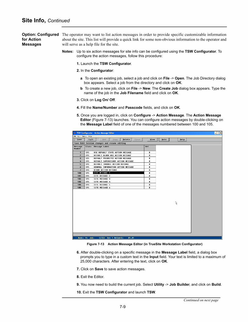
7-9
Site Info, Continued
Option: Configured for Action Messages
The operator may want to list action messages in order to provide specific customizable informationabout the site. This list will provide a quick link for some non-obvious information to the operator andwill serve as a help file for the site.
Notes: Up to six action messages for site info can be configured using the TSW Configurator. To configure the action messages, follow this procedure:
1. Launch the TSW Configurator.
2. In the Configurator:
a To open an existing job, select a job and click on File -> Open. The Job Directory dialog box appears. Select a job from the directory and click on OK.
b To create a new job, click on File -> New. The Create Job dialog box appears. Type the name of the job in the Job Filename field and click on OK.
3. Click on Log On/ Off.
4. Fill the Name/Number and Passcode fields, and click on OK.
5. Once you are logged in, click on Configure -> Action Message. The Action Message Editor (Figure 7-13) launches. You can configure action messages by double-clicking on the Message Label field of one of the messages numbered between 100 and 105.
Figure 7-13 Action Message Editor (in TrueSite Workstation Configurator)
6. After double-clicking on a specific message in the Message Label field, a dialog box prompts you to type in a custom text in the Input field. Your text is limited to a maximum of 25,000 characters. After entering the text, click on OK.
7. Click on Save to save action messages.
8. Exit the Editor.
9. You now need to build the current job. Select Utility -> Job Builder, and click on Build.
10. Exit the TSW Configurator and launch TSW.
Continued on next page

7-10
Site Info, Continued
Option: Configured for Action Messages
Click on Site Info to bring up the configured action messages in the Site Info tab. Figure 7-14 showsan example of a site info screen with four configured action messages.
Figure 7-14 Example of Site Info Screen Configured for Action Messages
Note: If the Action Messages are configured in a job that also contains graphics in a WGS format,clicking on the Site Info button will open the Graphics tab displaying the WGS graphic. Inorder to see a screen similar to Figure 7-14 instead, all WGS-format graphics need to bedeleted from the TSW job.

7-11
Point Simulate
Overview Note: When the TSW is configured as a supervising station (4190-8403 or 4190-8405), it cannot beallowed to be taken offline. Thus, the Point Simulate operation is not available to TSWconfigured as supervised stations. The TSW supervising station is not to be confused withsupervised Remote Client.
The Point Simulate button (Figure 7-15) provides access to the Simulator tab. It allows you to takethe system offline to simulate events in real time within a specific fire network loop. In simulationmode, the system will only display its responses towards events without affecting the TSW.
Figure 7-15 Point Simulate Button
Note: You may also access the Point Simulate command by pressing F8 on your keyboard, or byclicking on Point Simulate in the Utilities menu.
Enter Simulation Mode: Select a Loop
When the TSW enters simulation mode, it is disconnected from the fire network without breaking thefire network loop. This allows the operator to manipulate the states of external points locally. Withoutchanges seen elsewhere on the loop, the TSW will treat changes performed in the simulation mode asreal. However, results from events occurring in this mode will not be carried over in the realenvironment.
In order to enter the simulation mode, you must first select a loop by following this procedure:
1. From the Operations menu, click on Select Loop. The Select Network Loop dialog box appears.
2. In the dialog box, select the checkbox next to an available loop and click on OK.
Note: Only one TSW application at a time can select loops, and can either be the TSW applicationon the TSW PC, or the Remote Client application on a Remote Client PC.
The system enters in the simulation mode.
Exit Simulation Mode: Unselect a Loop
Warning: Once you select a loop, the system will remain in simulation mode until you set it back to real mode by deselecting the loop.
To exit the simulation mode in order to re-enter real mode, you must deselect the loop by followingthe following procedure:
1. From the Operations menu, click on Select Loop. The Select Network Loop dialog boxappears.
2. In the dialog box, deselect the checkbox next to the present loop and click on OK.
3. The system re-enters real mode.
Note: In case a real alarm occurs, the TSW will exit the simulation mode and display the real alarmwithin any fire network loop.
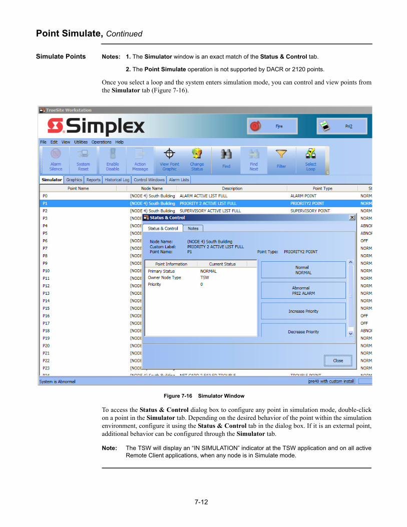
7-12
Point Simulate, Continued
Simulate Points Notes: 1. The Simulator window is an exact match of the Status & Control tab.
2. The Point Simulate operation is not supported by DACR or 2120 points.
Once you select a loop and the system enters simulation mode, you can control and view points fromthe Simulator tab (Figure 7-16).
Figure 7-16 Simulator Window
To access the Status & Control dialog box to configure any point in simulation mode, double-clickon a point in the Simulator tab. Depending on the desired behavior of the point within the simulationenvironment, configure it using the Status & Control tab in the dialog box. If it is an external point,additional behavior can be configured through the Simulator tab.
Note: The TSW will display an “IN SIMULATION” indicator at the TSW application and on all activeRemote Client applications, when any node is in Simulate mode.
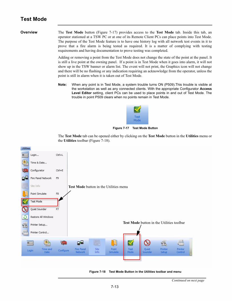
7-13
Test Mode
Overview The Test Mode button (Figure 7-17) provides access to the Test Mode tab. Inside this tab, anoperator stationed at a TSW PC or at one of its Remote Client PCs can place points into Test Mode.The purpose of the Test Mode feature is to have one history log with all network test events in it toprove that a fire alarm is being tested as required. It is a matter of complying with testingrequirements and having documentation to prove testing was completed.
Adding or removing a point from the Test Mode does not change the state of the point at the panel. Itis still a live point at the owning panel. If a point is in Test Mode when it goes into alarm, it will notshow up in the TSW banner or alarm list. The event will not print, the Graphics icon will not changeand there will be no flashing or any indication requiring an acknowledge from the operator, unless thepoint is still in alarm when it is taken out of Test Mode.
Note: When any point is in Test Mode, a system trouble turns ON (P509).This trouble is visible atthe workstation as well as any connected clients. With the appropriate Configurator AccessLevel Editor setting, client PCs can be used to place points in and out of Test Mode. Thetrouble in point P509 clears when no points remain in Test Mode.
Figure 7-17 Test Mode Button
The Test Mode tab can be opened either by clicking on the Test Mode button in the Utilities menu orthe Utilities toolbar (Figure 7-18).
Figure 7-18 Test Mode Button in the Utilities toolbar and menu
Continued on next page
Test Mode button in the Utilities menu
Test Mode button in the Utilities toolbar

7-14
Test Mode, Continued
Overview The Test Mode tab gives access to two minor tabs, Points and Groups. The Points minor tab isselected by default when the Test Mode tab is activated (Figure 7-19).
Note: The TSW allows you to turn on/off a filter row for typing in textual filters for one or multiplecolumns. To activate the filter, click on the icon on the top right corner of the main window.
Figure 7-19 Test Mode Tab with the Points Minor Tab Selected
The Points minor tab lists all the points that are currently in Test Mode. The Groups minor tab listsall the active test-mode groups for the current job.
When the Test Mode tab is active, the Test Mode submenu of the Edit menu, as well as the TestMode toolbar, become usable. The Test Mode submenu allows you to add or remove points fromTest Mode. Points can be selected individually, by category, by an entire DACR account, or by anentire 4120 node. Six options are available in the Edit menu.
• Add Points• Add Group• Remove Points• Modify Group• Save Group• Restore Group

7-15
Test Mode, Continued
Add Points The Add Points option allows the user to select points to be placed in Test Mode. When selecting thisoption, the Status & Control dialog box appears (Figure 7-20). You can then drag and drop pointsfrom that dialog box and into the Test Mode tab.
Figure 7-20 Status & Control Window for the Test Mode Tab
When a point is placed in Test Mode, the TSW provides a confirmation prompt (Figure 7-21)detailing which points have been placed in Test Mode and the timeout value of these points. The sameconfirmation prompt appears when a group of points is added (section Add Groups later in thischapter). The time-out value represents the date and time when points (or group of points) will beremoved from Test Mode. If the Never checkbox is selected, the points can only be removed fromTest Mode manually.
Continued on next page

7-16
Test Mode, Continued
Add Points
Figure 7-21 Confirm Test Mode Points
If attempting to add an invalid point to Test Mode, an error message is displayed.
Add Group The Add Group option allows you to add a group of points to be tested to a list of groups in the TestMode tab. When clicking on this option, a window prompting you to create a new test group willappear (Figure 7-22).
Figure 7-22 Add Group Wizard
Continued on next page

7-17
Test Mode, Continued
Add Group Follow the steps as they appear on the screen to create a new test group.The added group will appearwhen the Groups sub-tab is selected (Figure 7-23).
Figure 7-23 Test Point Group
Remove Points The Remove Points option enables you to remove any selected points/groups within the Test Modetab. Points can be removed by either selecting them in the Points or Groups sub-tabs within the TestMode tab, or by selecting a group name in the Groups sub-tab.When points are being taken out oftest-mode, the TSW prompts the user to either proceed or cancel to stay in Test Mode (Figure 7-24).Points in abnormal state will be added to the alarm list as soon as they are taken out of Test Mode.
Figure 7-24 Remove Points from Test Mode

7-18
Test Mode, Continued
Modify Group When you select the Modify Group option, a Modify Group dialog box (Figure 7-25) will appear. Inthis dialog box, you can change the point provider, the point categories, and the expiration time-outvalue.
Figure 7-25 Modify Group Dialog Box
You can add other points to the group by dragging and dropping them into it. In this case, the ModifyGroup wizard will display the MULTIPLE option in the Point Provider rolldown menu, as seen inFigure 7-26A. On the next page of the wizard, the new Customized checkbox also appears in thePoint Categories area of the dialog box (Figure 7-26B).
Figure 7-26 MULTIPLE Option and Customized Checkbox
In case of modifications to the group definitions, if you keep the MULTIPLE option selected and theCustomized checkbox checked, the new points that were added manually are kept in the group. Ifyou change the settings in the Point Provider rolldown menu or Point Categories area, the set ofpoints belonging to the group is re-evaluated and the ones that do not match the group settings areremoved from Test Mode.
A
B
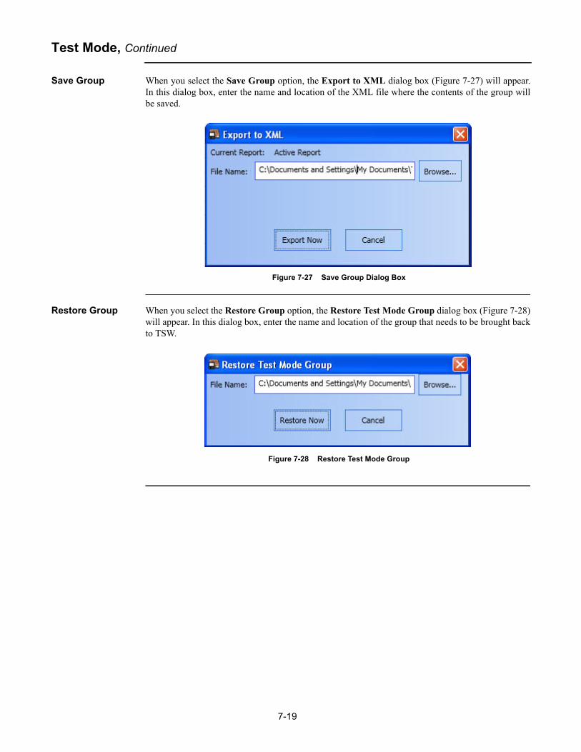
7-19
Test Mode, Continued
Save Group When you select the Save Group option, the Export to XML dialog box (Figure 7-27) will appear.In this dialog box, enter the name and location of the XML file where the contents of the group willbe saved.
Figure 7-27 Save Group Dialog Box
Restore Group When you select the Restore Group option, the Restore Test Mode Group dialog box (Figure 7-28)will appear. In this dialog box, enter the name and location of the group that needs to be brought backto TSW.
Figure 7-28 Restore Test Mode Group

7-20
Quiet Sounder
Overview The Quiet Sounder button (Figure 7-29) silences the PC sounder without acknowledging an alarmsignal. This operation is defaulted to access level 7 (service mode). Lower access levels areconfigurable. For UL compliant configurations, refer to table located in Configuration section ofChapter 1.
Figure 7-29 Quiet Sounder Button
Note: You may also access the Quiet Sounder command by pressing F7 on your keyboard.
Sounder Properties There are two cases when the sounder is triggered:
• When a new alarm event occurs: this is always the case regardless of whether or not there werepreviously unacknowledged alarm signals.
• When an alarm signal has been silenced, but remains unacknowledged: if the alarm remainsunacknowledged after a five-minute time-out period, its sounder is triggered again.
Note: The sounder is also triggered when there are incoming phone calls (Phone Control tab).However, they do not appear in the alarm list.

7-21
Restore All Windows
Overview The Restore All Windows command (Figure 7-30) sets all windows that are configured to dockableand floating mode to fixed mode in the main window area.
Figure 7-30 Restore All Windows Option

7-22
Printer Setup
Overview The Printer Setup button (Figure 7-31) allows you to setup available USB printers for the TSWsoftware.
Figure 7-31 Printer Setup Button
Clicking on the Printer Setup button will open the USB Printer Matchup dialog box. In this dialogbox you can see two types of USB printers available for the job:
• Supervised USB
• Non-supervised USB
Associated with each USB printer type is a drop-down box containing a list of configured USBprinters. That box would display “None” if no USB printers of that type are configured on thecomputer.
The USB printers of both types can be configured as event printers. Event printers are those set-up toprint specific, user-defined TSW events, such as alarms or troubles, and can be set-up on TSW PCsonly. The TSW Configurator is used to select the events and the USB printer they are to be printedto. This is done by accessing the Port Vectoring option under the Configure menu. You must selectthe printer type from the Ports window and the events from the Events window.
Note: When USB printers are configured as event printers in the job configuration, a USB PrinterMatchup dialog box will appear upon your login to the TSW. You can then specify which ofthe configured USB printers is to be used as an event printer. Event printing to a USB printerwill only be enabled when this is completed.

7-23
Printer Control
Overview The Printer Control button (Figure 7-32) displays the Printer Control dialog box, which providesprinter-related clean-up operations to be used in a situation when there is a printing problem. Forexample, an event printer may have been out of paper when system-generated events occurred. Inaddition to adding paper, the user may find that deleting the TSW’s internal buffer of queued events isneeded to restore TSW communication with the printer so that future events can be printed.
Figure 7-32 Printer Control Button
The Printer Control dialog box (Figure 7-33) displays the following controls:
• TSW Print Jobs: This tab enables you to terminate current and queued TSW print jobs such as Report, Screen and Graphics prints. This tab does not display TSW event print jobs.
Note: This tab shows TSW Print Jobs before they are sent to the Windowsspooler.
• Windows Printer Control: This tab enables you to terminate any current and queued jobs for a selected Windows Printer. This includes all TSW Print jobs, including event print jobs.
Note: This tab shows the same printer list that can be displayedfrom the Windows Control Panel. This is useful for TSWCaptive Mode systems where the Control Panel is notaccessible when TSW is running.
Figure 7-33 Printer Control Dialog Box
Clicking the Terminate print job button will terminate the selected print job. Clicking the FlushBuffer button will display the Flush Buffer dialog box (Figure 7-34). Clicking the Flush Bufferonce more will clear the print buffer of all the print jobs in the queue.
Figure 7-34 Flush Buffer Dialog Box
Note: The Flush Buffer option only applies to the TSW Event Print jobs.


8-1
Chapter 8. Help Menu
Introduction The Help menu, as shown in Figure 8-1, provides access to the following help options in the mainwindow:
• Help Topics
• Site Info
• Symbol Legend
• About TSW
• Feature Summary
• Type in Feature Code
Figure 8-1 Help Menu from Menubar View

8-2
Help Topics
Overview The Help Topics option allows you to view the help topics associated with different TSW softwarefunctionalities. Clicking on the Help Topics button inside the Help menu will bring up a dialog box(Figure 8-2) listing all the topics included in the TSW help file. If you only need to see a help topicassociated with a particular TSW functionality, you need to open that functionality and then press theF1 key on your keyboard. A dialog box with the help topic you specified will appear.
Note: Hitting the F1 button without a specific TSW function open will bring up all the help topics.
Figure 8-2 Help Topics Window

8-3
Site Info
Overview The Site Info in the Help menu is identical to the Site Info option in the Utilities menu in that itallows you to view the Site Info and the Graphics tabs. Refer to section “Site Info” in Chapter 7 formore details on this option.
Figure 8-3 Site Info Option

8-4
Symbol Legend
Overview The Symbol Legend option (Figure 8-4) allows you to view graphics containing legends that explainthe symbols in the drawings. The Symbol Legend option is only available if a job contains a graphicsscreen with the name _LEGEND.WGS. In this case, the graphics screen will be displayed whenSymbol Legend option is selected.
Figure 8-4 Symbol Legend Option

8-5
About TSW
Overview The About TSW option provides you the relevant TSW software information. However, informationappearing in the About TSW dialog box in a TSW PC (Figure 8-5) will differ from the one on a TSWRemote Client PC (Figure 8-6).
About TSW Dialog Box on a TSW PC
The About TrueSite Workstation dialog box on a TSW PC contains the TSW product description,application version, database revision, copyrights, licensing information, TSW job revision, and builddate. It also shows the number of Remote Client PCs connected to the TSW PC through TCP/IP andthe computer port used to communicate with them.
The Network Name and Description fields provide TSW fire network information. The NodeNumber field numbers the node currently in use. The Job Name field provides the name of the jobthat is currently open in the TSW PC. The Job Title field provides the description of the job and theComments field gives any additional information about the TSW.
Clicking on the Advanced button opens the Feature Summary dialog box, as seen in Figure 8-8.
Figure 8-5 About TrueSite Workstation Dialog Box on a TSW PC

8-6
About TSW, Continued
About TSW Dialog Box on a Remote Client PC
The About TrueSite Workstation dialog box on a Remote Client PC (Figure 8-6) contains the TSWproduct description, application version, database revision, copyrights, licensing information, TSWjob revision, and build date. The Workstation Identifier field lists the computer name of the TSWPC to which the Remote Client PC is connecting.
The TCP/IP Port and This PC fields identify the computer port used by the TSW application forcommunication, as well as the state of the Remote Client PC. The Vectored by field identifies thetype of vectoring for this Remote Client PC.
The Network Name and Description fields provide TSW fire network information. The Job Namefield provides the name of the job that is currently open in the Remote Client PC. The Node Numberfield numbers the node currently in use. The Job Title field provides the description of the job andComments field gives any additional information about the TSW.
Click on the Advanced button to open the Feature Summary dialog box, as seen in Figure 8-8.
Figure 8-6 About TSW Dialog Box on a Remote Client PC
Click on the Vectoring button to open the Vectoring Details for this TSW client dialog box (Figure 8-7). This dialog box is read only.
Note: If the TSW Remote Client is not vectored, the Vectored by field and the Vectoring button donot appear in the About TrueSite Workstation dialog box.
Continued on next page

8-7
About TSW, Continued
About TSW Dialog Box on a Remote Client PC
Figure 8-7 Vectoring Details for this TSW Client

8-8
Feature Summary
Overview The Feature Summary option provides information on the individually purchased features that havebeen installed in the TSW software. Those features can be purchased after the basic TSW softwarehas been installed. They require a unique client dongle key and Feature Code to be activated. Refer toChapter 12 for more information.
The Feature Summary dialog box (Figure 8-8) can be accessed by clicking on Help and then onFeature Summary. Another way is to click on Help, About TSW and then on Advanced....
Figure 8-8 Feature Summary Dialog Box with Job Misalignment Note
After a feature has been installed and enabled in the TSW software, the application may need to berestarted to work. The Feature Summary dialog box provides a note when this is needed. This notewill appear beneath the table outlining the features installed, and above the More Info section thatcan be seen in Figure 8-8.
The Feature Summary dialog box also informs you of any problems between the installed featureand the TSW software. A note stating this problem will also appear above the More Info section thatcan be seen in Figure 8-8.
The More Information... button provides further details on the status of the different licensingservices of the TSW software.

8-9
Feature Code
Overview The Type In Feature Code dialog box (Figure 8-9) allows you to type in a unique code used to installand unlock separately purchased features for the TSW software. It can be accessed by clicking onHelp and then on Type in Feature Code. Refer to Chapter 12 for more information on this option.
Figure 8-9 Feature Code Dialog Box
When a Feature Code is entered in the Type In Feature Code dialog box, and the OK button isclicked, a subfolder called TrueSite Workstation is created in the Documents folder of the currentWindows user. Inside, the Feature Code that has just been entered is saved within a text file calledFeature Code.txt. Only the latest entered Feature Code is saved. Whenever a new one is entered, theold Feature Code.txt file is overwritten with the one containing the latest Feature Code used. Thisfunctionality is automatic and cannot be disabled.
Note: After entering a feature code, it is recommended that the Feature Summary dialog box beinvoked to confirm the features have been installed. Afterwards, invoke these features withinTSW to verify the operation is enabled.

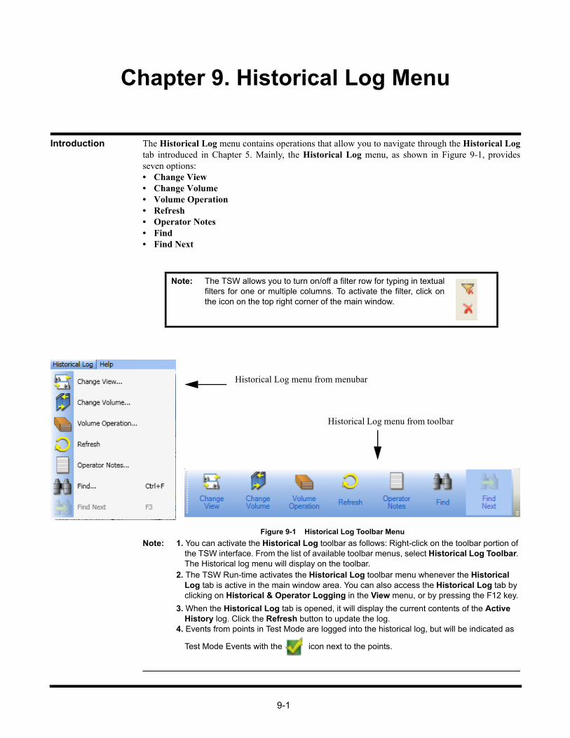
9-1
Chapter 9. Historical Log Menu
Introduction The Historical Log menu contains operations that allow you to navigate through the Historical Logtab introduced in Chapter 5. Mainly, the Historical Log menu, as shown in Figure 9-1, providesseven options:• Change View• Change Volume• Volume Operation• Refresh• Operator Notes• Find• Find Next
Figure 9-1 Historical Log Toolbar Menu
Note: 1. You can activate the Historical Log toolbar as follows: Right-click on the toolbar portion of the TSW interface. From the list of available toolbar menus, select Historical Log Toolbar. The Historical log menu will display on the toolbar.
2. The TSW Run-time activates the Historical Log toolbar menu whenever the Historical Log tab is active in the main window area. You can also access the Historical Log tab by clicking on Historical & Operator Logging in the View menu, or by pressing the F12 key.
3. When the Historical Log tab is opened, it will display the current contents of the Active History log. Click the Refresh button to update the log.
4. Events from points in Test Mode are logged into the historical log, but will be indicated as
Test Mode Events with the icon next to the points.
Note: The TSW allows you to turn on/off a filter row for typing in textualfilters for one or multiple columns. To activate the filter, click onthe icon on the top right corner of the main window.
Historical Log menu from menubar
Historical Log menu from toolbar

9-2
Change View / Change Volume
Overview The Change View button (Figure 9-2) allows you to change the display conditions of the grid in theHistorical Log tab.
Figure 9-2 Change View Button
The Change Volume button (Figure 9-3) allows you to run through the log in order to view a selectedportion of the historical log. By default, there are two volumes and the total number of volumes is setin the job configuration.
Figure 9-3 Change Volume Button
Change Historical Log Display Conditions
To change the historical log display conditions:
1. Click on Historical Log in the major tab area to bring up its content in the main window.
2. From the Historical Log toolbar menu, click on Change View.
The Historical Log Volume/ View Selection dialog box appears as shown in Figure 9-4.
Figure 9-4 Historical Log Volume/View Selection Dialog Box
Note: At any time, you may click on Cancel to dismiss the dialog box without taking any action.
3. You must select a volume and a view in the corresponding lists:
a. To select a volume, click on an entry in the Highlight Volume list.
b. To select a view, click on an entry in the Highlight View list.
4. After selecting a volume and a view, click OK. The Historical Log tab should update to the newdisplay conditions.

9-3
Change View / Change Volume, Continued
Edit a View Note: The following procedure only concerns the scenario where the selected view is editable.Editable views are originally unused and are customizable. Default views that are pre-programmed cannot be edited.
To edit a view:
1. Select an entry from the Highlight View list in the Historical Log Volume/View Selection dialogbox.
2. Click on Edit View. A Custom View Configurator dialog box appears, as shown in
Figure 9-5.
Figure 9-5 Custom View Configurator Dialog Box
Note: At any time, you may click on Cancel to dismiss the dialog box without taking any action.
3. In the Custom View Configurator dialog box, you must set the following parameters:
• Custom View Name - Enter an alphanumerical string.
• Core View - Select one of the following options from the dropdown list:
- Entire- Fire Alarm- Priority 2 Alarm- Supervisory- Trouble- Control- Diagnostic- Operator
• Time Range (hh/mm/ss) - Enter the From: and To: values following the indicated format to set a range.
• Date Range (mm/dd/yy) - Enter the From: and To: values following the indicated format to set a range.
Continued on next page

9-4
Change View / Change Volume, Continued
Edit a View Note: Step 4 is optional and is used to modify advanced view settings.
4. Click on Advanced. The Advanced View Options dialog box appears as shown in Figure 9-6.From this dialog box, you can include points by selecting the checkboxes and providing a stringfor the following parameters (click on OK to confirm entries):
• Network
• Node
• Point Name
• DACR Account
You can also select the type of Operator Notes that are going to be displayed, as well as indicateto display only the points that are in test mode, by selecting:
• Notes Without Events
• Events Without Notes
• Only Include Test Mode Points
Figure 9-6 Advanced View Options Dialog Box
Note: At any time, you may click on Cancel to dismiss the dialog box without taking any action.
5. Finally, click on OK to confirm new display settings.
Erase a View To erase a view:
1. Select an entry from the Highlight View list in the Historical Log Volume/View Selection dialogbox.
2. Click on Erase View. A prompt dialog box will ask you “Do you really want to Erase View?”.
3. Click on OK to confirm. The view is erased from the list.

9-5
Volume Operation
Overview The Volume Operation button (Figure 9-7) allows you to open the Historical Log VolumeOperations dialog box (shown in Figure 9-8) which lists existing historical log volumes and providesthe following options:
• Label
• Delete
• Export
• Backup
• Restore
• Close
• Close active volume
Figure 9-7 Volume Operation Button
Figure 9-8 Historical Log Volume Operations Dialog Box
Note: 1. At any time, you may click on Close to dismiss the dialog box.
2. At any time, you may click on Close active volume and open a new one to begin recording events. A given volume can only be closed if there is at least one unused historical log volume remaining. The total number of configured volumes can be specified in the hardware configuration of the job.

9-6
Volume Operation, Continued
Label a Volume 1. In the Historical Log Volume Operations dialog box, select a label from the list under Select avolume to act on.
2. With the selected volume highlighted, click on Label.
3. A Change Volume Label dialog box appears, as shown in Figure 9-9. From this dialog box,enter the new label in the New volume label text field.
Figure 9-9 Change Volume Label Dialog Box
4. Click on OK to confirm the label change.
Note: At any time, you may click on Cancel to dismiss the dialog box without taking any action.
Delete a Volume Note: 1. You can only delete a volume that is not currently being viewed.
2. The TSW does not allow you to delete a volume if it is the active volume (the volume cur-rently recording incoming events).
1. To delete a volume, select a label from the list under Select a volume to act on.
2. With the selected volume highlighted, click on Delete. A prompt dialog box will ask you Are yousure you want to delete the highlighted volume?
3. Click on Yes to confirm.
Export a Volume 1. In the Historical Log Volume Operations dialog box, select a label from the list under Select avolume to act on.
2. With the selected volume highlighted, click on Export.
3. An Export Volume dialog box appears, as shown in Figure 9-10. From this dialog box, set thefollowing parameters:
• Filename: - Enter an alphanumerical string. (By default, this field is “C:\HLEXPORT”)
• File format: - Select one of the following two options by selecting the corresponding radio button:
- ASCII text (default)- Comma delimited text
Note: You may select a drive other than A:\ to export a volume by simply inserting it in front of thefilename, for example: “C:\HLEXPORT.TXT”.
Continued on next page

9-7
Volume Operation, Continued
Export a Volume
Figure 9-10 Export Volume Dialog Box
4. Once you have configured the export settings, click on Export Now.
The volume is exported according to settings.
Backup a Volume Note: Make sure to label your backup disks for simple reference in case you need to restore avolume.
1. Insert the storage media (USB key or CD) into the appropriate drive or port.
2. In the Historical Log Volume Operations dialog box, select and highlight a label from the listunder Select a volume to act on.
3. With the selected volume highlighted, click on Backup.
4. A Back up Volume dialog box appears as shown in Figure 9-11.
Figure 9-11 Back Up Volume Dialog Box
5. Provide the filename of the backup log.
6. Click on Back Up Now.
The volume log is backed-up on the CD or a USB key.
Note: You may select a drive other than d:\ to backup a volume by simply inserting it in front of thefilename, for example: “C:\HLEXPORT.TXT”.

9-8
Volume Operation, Continued
Restore a Volume 1. Insert a storage media (USB key or CD) with the backup file in the appropriate drive or port.
2. In the Historical Log Volume Operations dialog box, select a label from the list under Select avolume to act on.
3. With the selected volume highlighted, click on Restore.
4. A Restore Volume dialog box appears, as shown in Figure 9-12.
Figure 9-12 Restore Volume Dialog Box
5. Provide the File Name of the backup log you want to restore.
6. Click on Restore Now.
The volume log is restored
Note: You may select a drive other than A:\ to restore a volume by simply inserting it in front of thefilename, for example: “C:\HLEXPORT.TXT”.

9-9
Operator Notes
Overview The Operator Notes button (Figure 9-13) allows you to add notes to a volume.
Figure 9-13 Operator Notes Button
Add a Note to an Event
To add a note to an event in the Historical Log:
1. Click on Historical Log in the major tab area to bring up its content in the main window.
2. Select an event from the list within the main window.
3. From the Historical Log toolbar menu, click on Operator Notes.
4. The Add Operator’s Note dialog box appears, as shown in Figure 9-14.
Figure 9-14 Add Operator’s Note Dialog Box
5. Under Associate Note With, select Highlighted Event.
6. Type a note in the main field, which will be associated with the highlighted event.
7. Once you have finished, click on OK.

9-10
Refresh
Overview The Refresh button (Figure 9-15) allows you to update the view on display with the latest appropriatehistorical log entries. This will be done if the active volume has changed and if one or more of thenew entries match the current view.
Figure 9-15 Refresh Button

9-11
Find / Find Next
Overview The Find button (Figure 9-16) allows you to search the list of system points by matching one of thethree options:
• by point name
• by point label
• by text
The Find Next (Figure 9-16) button allows you to view the next point in the list.
Figure 9-16 Find and Find Next Buttons
Note: The F3 button on the keyboard invokes the Find menu if no previous searches were made.
Find a Specific Point
To find a point:
1. Click on the Historical Log tab in the major tab area to bring up its content in the main window.
2. From the Historical Log toolbar menu, click on Find.
3. The Find Selected Point dialog box appears, as shown in Figure 9-17.
Figure 9-17 Find Selected Point Dialog Box
4. Type in either the port name, the label, or the text of a point you want to find.
5. Select one of the following search options:
• By Point Name
• By Point Label
• By Point Text
6. Click on OK.
If the Find operation is successful, the Find Next button becomes available.
Note: At any time, you may click on Cancel to dismiss the dialog box without taking any action.


10-1
Chapter 10. Reports Menu
Introduction The Reports menu allows you to generate, view, and print reports on specific events occurring withinthe fire system network. You can also generate a report of all test mode events. As shown inFigure 10-1, three options are available from this menu:
• Generate
• Terminate
• Clear
Figure 10-1 Reports Menu from Menubar and Toolbar Views
Notes: 1. To be able to access the Reports toolbar menu, you must first activate it as follows: right-click on the toolbar portion of the TSW interface. From the list of available toolbar menus, click on Reports Toolbar. The Reports menu will display on the toolbar.
2. By default, the TSW activates the Reports toolbar menu whenever the Reports window is active in the main window area. You may choose to hide the toolbar menu. You can also activate the Reports toolbar and menubar by clicking on Reports in the View menu.
Reports menufrom menubar
Reports menu from toolbar

10-2
Generate / Terminate
Overview The Generate button (Figure 10-2) allows you to generate five types of reports:
• Historical log report
• TrueAlarm service report
• TrueAlarm status report
• AMZ calibration report
• Active list report
Figure 10-2 Generate Button
The Terminate button (Figure 10-3) allows you to end an ongoing report generation.
Figure 10-3 Terminate Button
Generate a Report To generate a report:
1. From the Reports toolbar menu, click the Generate button.
The Report Selection dialog box appears, as shown in Figure 10-4.
Figure 10-4 Report Selection Dialog Box
2. Select the type of report you want to generate and click Generate. The report will be displayedon the screen.
Once a report has been generated, it can either be saved, printed or cleared. To save or print the report,please see the sections “Save Report” and “Print Report” in Chapter 3. To clear a report, see section“Clear” in this chapter.
Terminate a Report Generation
While a report is currently being generated, click on Terminate in the Reports menu to end thegeneration.

10-3
Clear
Overview The Clear button (Figure 10-5) allows you to delete the report that is currently displayed in theReports window.
Figure 10-5 Clear Button
The Clear button can also be accessed by opening the Reports menu option (Figure 10-6).
Figure 10-6 Clear Button Accessed
Note: The Reports menu option will only be available if the Reports window is selected. Otherwise,it is not displayed.

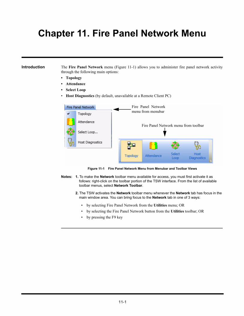
11-1
Chapter 11. Fire Panel Network Menu
Introduction The Fire Panel Network menu (Figure 11-1) allows you to administer fire panel network activitythrough the following main options:
• Topology
• Attendance
• Select Loop
• Host Diagnostics (by default, unavailable at a Remote Client PC)
Figure 11-1 Fire Panel Network Menu from Menubar and Toolbar Views
Notes: 1. To make the Network toolbar menu available for access, you must first activate it as follows: right-click on the toolbar portion of the TSW interface. From the list of available toolbar menus, select Network Toolbar.
2. The TSW activates the Network toolbar menu whenever the Network tab has focus in the main window area. You can bring focus to the Network tab in one of 3 ways:
• by selecting Fire Panel Network from the Utilities menu; OR
• by selecting the Fire Panel Network button from the Utilities toolbar; OR
• by pressing the F9 key
Fire Panel Networkmenu from menubar
Fire Panel Network menu from toolbar

11-2
Topology
Overview The Topology button (Figure 11-2) allows you to view the representation of the connections betweenthe nodes in the system that are communicating with the TSW (the current node). All nodes aredisplayed relative (left or right) to all other nodes currently online.
Notes: 1. A node that has lost communication but that was previously online will be crossed out (marked with an “X”). After a few seconds, it will disappear from the network topology diagram.
2. Either Topology or Attendance is always selected (not both at the same time). The selected option is selected in the menubar or in the toolbar.
Figure 11-2 Topology Button
View Fire Panel Network Topology
Note: By default, when you select the Network tab, it displays the Network Information minor taband shows either the topology or attendance, depending on what was last viewed.
To view a fire panel network topology:
1. Click on Topology from the Network menu.
2. The fire panel network topology diagram is displayed in the Network tab, as shown in Figure 11-3.
Figure 11-3 Network Topology
In the Network tab, the different types of nodes are represented by graphical icons. In some cases,these icons are accompanied by one of the following labels to specify their roles:
• * - host node
• T - timekeeper node
• M - monitor node
Continued on next page

11-3
Topology, Continued
View the Fire Panel Network Topology
3. From the Network tab, you can perform the following operations by clicking the buttons at the lower-left corner of the main window:
• To view node information: select a node in the fire panel network topology diagram and click About Node. The About Node dialog appears as shown in Figure 11-4.
• To view channel status: select a node in the fire panel network topology diagram and click Channel Status. The Channel Status Information dialog appears as shown in Figure 11-5.
Note: By default, the Channel Status button is not available (grayed-out) on a Remote Client PC.
Figure 11-4 About Node Dialog Box
A channel is a 4120 fire network resource available network-wide which will be used by TerminalMode, Network Download and Diagnostics, for the data transfer between nodes.
The Channel Status function allows you to verify the availability of 4120 fire network resources thatare currently being requested for a specific node. It shows whether or not they are currently beingused by other nodes, thus preventing the requesting node from successfully accessing a data channel.
The following information is displayed when you request the channel’s status.• Network Number - number assigned to the 4120 fire panel network in the Network Programmer• Network Title - title assigned to the 4120 fire panel network in the Network Programmer• Host Logical Node # - node number specific to the TSW• Host Physical Node # - node number specific to the TSW• Operation Status - normal (default) or abnormal
Figure 11-5 Channel Status Information Dialog Box
Note: Channel 2 is never used.

11-4
Attendance
Overview The Attendance button (Figure 11-6) allows you to analyze the attendance of devices within the firepanel network. The Attendance diagram represents the configured nodes in the fire panel network.
Notes: 1. A node that has lost communication but that was previously online will be crossed out (marked with an “X”). After a few seconds, it will disappear from the network topology diagram.
2. Either Topology or Attendance is always selected (not both at the same time). The selected option is selected in the menubar or in the toolbar.
Figure 11-6 Attendance Button
View Fire Panel Network Attendance
To view the fire panel network attendance, click on Attendance from the Fire Panel Network menu.The Attendance diagram will be displayed in the Network tab.

11-5
Select Loop
Overview The Select Loop button (Figure 11-7) allows you to change from one fire panel network loop toanother. This operation is available only if the job is multi-loop built.
Figure 11-7 Select Loop Button
Notes: 1. The Select Loop button is available only when the Network tab is selected in the major tab area.
2. The Select Loop button is not available if Terminal Mode of Network Download is in progress.
3. Be advised that the Select Loop button from the toolbar does not perform the same oper-ation as the Select Loop option, which is used with Point Simulate, in the Operations menu. The operation described in this section strictly concerns the selection of a loop in real mode.
Select a Fire Panel Network Loop in Real Mode
When multiple loops are configured in the fire panel network, you may choose to view theinformation for a specific loop:
1. Click on the Network tab in the major tab area to open it in the main window.
2. Click on Select Loop in the Fire Panel Network menu.
A Select Network Loop dialog box appears, as shown in Figure 11-8.
Figure 11-8 Select Network Loop Dialog Box
Note: By default, Loop 1 is selected (Figure 11-8). Only one loop at a time can be selected. On the Incident Commander, only two loops are available.
3. Under the NETWORK: list, check one of the enabled radio button next to the loop you want toselect (grayed-out checkboxes are non-selectable).
4. Click on OK to confirm your selection.
You now have access to the information for that specific loop under Network minor tabs. All changesperformed in the minor tabs will affect the status of the selected network loop.

11-6
Host Diagnostics
Overview Note: By default, the Host Diagnostics button is not available (grayed-out) on a Remote Client PC.
The Host Diagnostics button (Figure 11-9) allows you to monitor a 4120 fire network and its hostcommunication.
Figure 11-9 Host Diagnostics Button
View Host Diagnostics
To view host diagnostics, click on Host Diagnostics in the Network menu. The NetworkDiagnostics dialog box will be displayed in the Network tab, as shown in Figure 11-10.
Figure 11-10 Network Diagnostics Dialog Box
Note: The Messages Received row also includes Diagnostic and Normal 4120 Fire Networkcommunications messages.
Start Messages Clicking on Start Messages creates a connection on the 4120 fire network which enables networkmonitoring. The messages relayed display the 4120 fire network diagnostic statistics.
Stop Messages Clicking on Stop Messages causes the system to stop receiving information, without clearing theexisting messages.
Clear Tallies Clicking on Clear Tallies removes the current information from the Network Diagnostics dialog boxwithout stopping the system from updating information.
Exit Clicking on Exit clears all information and stops the current 4120 fire network connection.

11-7
Minor Tab Buttons
Overview When the Network tab in the major tab area is selected, the Network section is displayed in the mainwindow with three buttons in the minor tab area (Figure 11-11):
• Network Information
• Terminal Mode
• Network Download
Figure 11-11 Minor Network Tab Bar
Network Information
By default, when you click on Fire Panel Network from the Utilities menu, the Network tabdisplays the topology screen with the Network Information minor tab selected. Under this tab, youcan perform all the commands previously described in this chapter.
Terminal Mode Clicking on the Terminal Mode minor tab will activate its options. Under this tab (refer to Figure 11-12), two commands are available: Open session and Terminate session.
Note: By default, the Terminal Mode tab is not available (grayed-out) on all Remote Client PCs.
Figure 11-12 Active Terminal Mode Minor Tab
Continued on next page

11-8
Minor Tab Buttons, Continued
Terminal Mode • To open a session:
1. Click on Open Session.
2. In the list of nodes presented in the Open Session dialog box, highlight the node for which you want to open a session and click on OK.
The Open Session dialog box closes. You can monitor the progress of the session from the mainwindow under the Terminal Mode minor tab.
• To terminate a session, click Terminate Session.
The following keyboard mappings can only be used within the Terminal Mode tab:
Note: When there are multiple users attached through remote clients to the TSW, only one user at atime can have an open Terminal Mode Session. Therefore, when the Terminal Mode sessionis open at one PC, all other TSW Clients will disable the Terminal Mode Open Sessionbutton.
Table 11-1: Keyboard Sequences and their Functions
Keyboard Sequence Function
F6 Activate Terminal mode from CRT mode
Alt F7 F17 - Local bell silence
Alt F8 F18 - Main Menu (CRT)
Alt F9 F19 - Previous Menu (CRT)
Num Lock PF1 - Acknowledge
Keypad/ PF2 - Alarm Silence
Keypad* PF3 - System Reset, Reports: next page to screen
Keypad - PF4 - Login, Reports: return to menu
Ctrl A Acknowledge (COMMAND)
Ctrl S Signal Silence (COMMAND)
Ctrl D System Reset (COMMAND)
Ctrl T Stop Scrolling (COMMAND)
Ctrl S Stop Scrolling (CRT)
Ctrl Q Resume Scrolling (CRT)
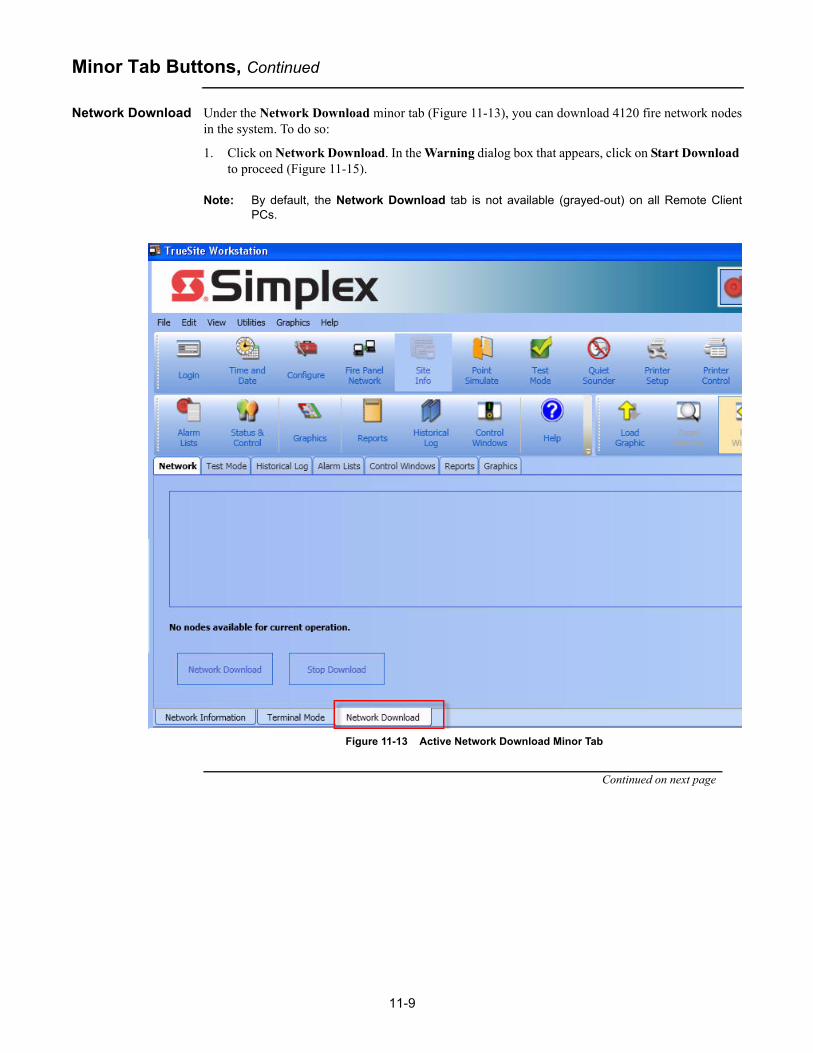
11-9
Minor Tab Buttons, Continued
Network Download Under the Network Download minor tab (Figure 11-13), you can download 4120 fire network nodesin the system. To do so:
1. Click on Network Download. In the Warning dialog box that appears, click on Start Download to proceed (Figure 11-15).
Note: By default, the Network Download tab is not available (grayed-out) on all Remote ClientPCs.
Figure 11-13 Active Network Download Minor Tab
Continued on next page

11-10
Minor Tab Buttons, Continued
Network Download
Figure 11-14 Download Warning Dialog Box
2. From the Network Download Operation dialog box, two actions are available:
a.Download a node: select the node you want to download from this dialog box, then clickon OK.
Figure 11-15 Network Download Operation Dialog Box
b.View the information of a job: select the job and then click on More Info. The JobInformation dialog box appears, as shown in Figure 11-16.
Note: To select multiple jobs to download, use one of the following method:
• Hold CTL+click multiple jobs• Hold SHIFT + click on the first job and then on the last job in the range of the desired jobs • Hold SHIFT + use the down arrow to select multiple jobs
Continued on next page

11-11
Minor Tab Buttons, Continued
Network Download
Figure 11-16 Job Information Dialog Box
After selecting a job to download from the list, the job download progress can be monitored from themain window, as shown in Figure 11-17, under the Network Download minor tab.
3. To interrupt and cease a download, click on Stop Download.
Figure 11-17 Monitoring Network Download from the Main Window

12-1
Chapter 12. Licensing
Introduction The licensing mechanism provides protection against unauthorized access and installation of theTSW software. This protection is performed through a unique customer dongle and a Feature Codeassociated with each workstation running the TSW software. The dongle and Feature Code are usedtogether as a pair. A Technical Representative (TR) / Maintenance dongle can also be used to run theTSW software, but with various access and time restrictions. This chapter deals with the followingfeatures of the licensing mechanism:
• Lock/Unlock one or multiple individually purchasable TSW features• Prevent the TSW software from running long-term with an incorrect or missing dongle
Note: No dongle or feature code is required on a Remote Client PC.
Dongle Types Various dongle types can be used to run the TSW software. However, not all provide unlimited accessto all the TSW features. Some also provide a time limit to open the TSW application. The following isa list of all the dongle types that can be used to run TSW under some form:
TSW Dongle
The TSW dongle is a unique customer dongle that is used together with a unique Feature Code. Theyare associated with each TSW PC running the TSW software. Both are used to unlock certain featuresfor the TSW software, as will be discussed in the section “Lock/Unlock one or multiple individuallypurchasable TSW features”.
Note: The Remote Client PCs do not use the TSW dongle and the Feature Code.
TSW DACR Dongle
The legacy TSW DACR dongle has the individually purchasable DACR feature burned in it. Thisdongle can also be used with a Feature Code. However, the TSW software will only enable the DACRfeature, regardless of the setting in the Feature Code, unlike the TSW dongle that can unlock anyfeature programmed in the Feature Code.
TrueSite Graphic Annunciator Dongle
The TrueSite Graphic Annunciator dongle is used to run a “view-only” version of the TSW, wherenone of the “Control Features” can be used. These features can be enabled by using a Feature Codethat unlocks the TSW functionalities.
The following operations are not allowed when a TrueSite Graphic Annunciator dongle is usedwithout a Feature Code:
• Only Status lines (no control buttons) are displayed inside the Status and Control tab• Any/All Graphics Command Links involving Point or System Control• Control Windows tab• Point Simulate tab• Test Mode tab• Network Terminal Mode tab• Network Download tab• Email Configuration• Historical Log Notes or Volume Operations
Continued on next page
12-2
Introduction, Continued
Dongle Types TR/Maintenance Dongle
The TR dongle is used by field technicians for product installation and maintenance purposes. TheTR dongle works short-term for any TSW workstation installation, including a test installation on thetechnician’s computer. The TR dongle gives the technician the ability, through an Administrator’sSettings dialog box, to:
• Unlock individually protected features based on the Feature Code
• Unlock all individually protected features
• Run only the basic TSW features.
Notes: 1. As of version 2.01, The TSW application will no longer operate with IMS type dongles. Select Help from the TSW runtime application to view the current dongle type. Please contact your sales representative to obtain a TSW type dongle if necessary.
2. The Administrator’s Settings dialog box must be used in order to allow remote clients to connect when using a TR dongle. Then, select either Unlock features based on feature code or Unlock all features. In order to use the Administrator’s Settings dialog box, logging-on under the username 512 (level 7) is required.
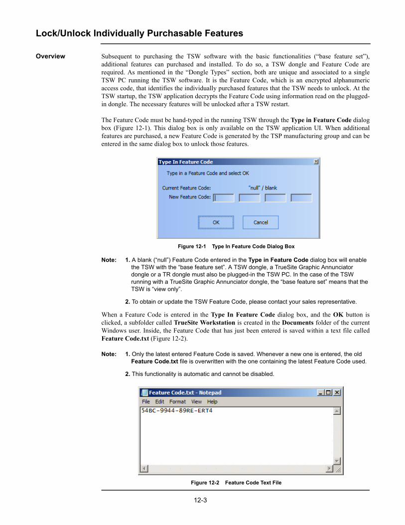
12-3
Lock/Unlock Individually Purchasable Features
Overview Subsequent to purchasing the TSW software with the basic functionalities (“base feature set”),additional features can purchased and installed. To do so, a TSW dongle and Feature Code arerequired. As mentioned in the “Dongle Types” section, both are unique and associated to a singleTSW PC running the TSW software. It is the Feature Code, which is an encrypted alphanumericaccess code, that identifies the individually purchased features that the TSW needs to unlock. At theTSW startup, the TSW application decrypts the Feature Code using information read on the plugged-in dongle. The necessary features will be unlocked after a TSW restart.
The Feature Code must be hand-typed in the running TSW through the Type in Feature Code dialogbox (Figure 12-1). This dialog box is only available on the TSW application UI. When additionalfeatures are purchased, a new Feature Code is generated by the TSP manufacturing group and can beentered in the same dialog box to unlock those features.
Figure 12-1 Type In Feature Code Dialog Box
Note: 1. A blank (“null”) Feature Code entered in the Type in Feature Code dialog box will enable the TSW with the “base feature set”. A TSW dongle, a TrueSite Graphic Annunciator dongle or a TR dongle must also be plugged-in the TSW PC. In the case of the TSW running with a TrueSite Graphic Annunciator dongle, the “base feature set” means that the TSW is “view only”.
2. To obtain or update the TSW Feature Code, please contact your sales representative.
When a Feature Code is entered in the Type In Feature Code dialog box, and the OK button isclicked, a subfolder called TrueSite Workstation is created in the Documents folder of the currentWindows user. Inside, the Feature Code that has just been entered is saved within a text file calledFeature Code.txt (Figure 12-2).
Note: 1. Only the latest entered Feature Code is saved. Whenever a new one is entered, the old Feature Code.txt file is overwritten with the one containing the latest Feature Code used.
2. This functionality is automatic and cannot be disabled.
Figure 12-2 Feature Code Text File

12-4
Lock/Unlock Individually Purchasable Features, Continued
Feature Summary Dialog Box
A runtime Feature Summary dialog box (Figure 12-3) provides information on the features and onthe dongle that is currently installed on the PC. More specifically, it displays:
• The current Feature Code
• The plugged-in dongle type and dongle serial number
• All possible software features that can be purchased through the current Feature Code
• The actual configured features
• The features that the Feature Code has unlocked.
The More Information... button provides further details on the status of the different licensingservices on the TSW software.
Figure 12-3 Feature Summary Dialog Box

12-5
TSW Software Missing Customer Dongle
Overview The TSW software is not allowed to run long term without a proper dongle plugged-in. To meet thisrequirement, at the TSW start-up, TSW starts a shutdown timer when it detects either an invalid TSW,TrueSite Graphic Annunciator or TR dongle, or no dongle at all. Once the shutdown timer expires,the TSW automatically quits running and cannot be restarted with the individually purchased featuresenabled, without a valid dongle plugged-in.
Note: An invalid TSW dongle is one that does not match the Feature Code.
The period of time the TSW software can run without a correct dongle will be based on whether a TRdongle is connected, or if there is an invalid (or missing) TSW or TrueSite Graphic Annunciatordongle.
TR Dongle Connected
If a TR dongle is connected when the TSW application starts, the latter would then run for a period oftime known as a “TR grace period”. When that period expires, TSW will automatically shutdown.
The “TR grace period” is session-duration based, which means that the technician has eight hours toperform the necessary task on the TSW software. The “TR grace period” is reset every time the TSWapplication is started with a TR dongle.
There is a message that appears on the screen informing that a TR dongle is attached and the machinewill reboot in 8/6/4/2 hours. When the TR dongle is installed, an entry regarding the detection of amaintenance dongle appears every 2 hours in the event log.
Invalid TSW or TrueSite Graphic Annunciator Dongle Connected
If there is no dongle present during TSW startup (or if an invalid TSW or TrueSite GraphicAnnunciator dongle is plugged-in), the TSW application will run with the Feature Code-identifiedfeatures unlocked for a set time period, known as the “user grace period”, for 72 hours. If the TSW isto be restarted after that period of time without a valid dongle, then it will run with only the “basefeature set” enabled.
The “user grace period” is PC-clock based and not session-duration based. This means that it startsthe first time the TSW is launched and expires 72 hours later. For example, if the user accessed theTSW at 10:45am, August 1, 2010, the TSW will automatically shutdown and will not restart withFeature Code-identified tools after 10:45, August 4, 2010, unless a valid dongle is plugged-in.
Note: The TSW application can be run with the “base feature set” enabled if any dongle, TSWdongle, TrueSite Graphic Annunciator dongle or TSW DACR dongle, is plugged-in. In thecase of the TSW running with a TrueSite Graphic Annunciator dongle, the “base feature set”means that the TSW is “view only”.
If the TSW is restarted with a valid dongle (dongle serial number matching the Feature Code), thetimer is reset and the Feature Code-protected features are unlocked.
Auto Restart/ Shutdown when Dongle Change
If a dongle is pulled out or swapped while the TSW is running, the TSW will record the dongle statechange in the Historical Log, with a timestamp. Within 5 minutes, it will also display a dialog boxwarning that TSW is about to shutdown (Figure 12-4). The TSW will shutdown when this dialog boxis closed, either by the user or automatically after 60 seconds.
Figure 12-4 Shutdown or Restart Dialog Box

12-6
TSW Software Missing Customer Dongle, Continued
Restricted Mode If the grace period has expired and neither a TR dongle, nor a valid TSW or TrueSite GraphicAnnunciator dongle is plugged-in, the TSW application goes into a non-operational mode in whichonly a limited menu is displayed. In this mode, only the following options and dialog boxes can beaccessed:
• Feature Summary dialog box.
• Type in Feature Code dialog box (to type a new Feature Code).
• Restart the TSW option.
• Exit to the Windows desktop option.

13-1
Chapter 13. TSW Remote Client
Introduction The TSW Remote Client software is used to access the TSW from a remote computer, called aRemote Client PC. That Remote Client PC has to be located on the same TCP/IP network as the TSWPC. The Remote Client software comes on the same TSW installation CD as the TSW andConfigurator applications. However, the Remote Client PC only needs the Remote Client applicationinstalled. The other two applications are not necessary to connect to the TSW PC.
The TSW Remote Clients can be divided in two groups:
• Supervised• Non-supervised
Upon connecting to the TSW PC through TCP/IP, the Supervised Remote Client is prompted tospecify a slot name, or number, when connecting to the TSW PC. The number will identify thisprecise Remote Client, in case other Remote Clients connect to the TSW application. It will also beused to notify the TSW PC when that Remote Client is disconnected.
The Non-supervised Remote Client does not get a prompt to specify its slot name or number, and canthus disconnect from the TSW server without any notification.
Note: A Remote Client can be set-up to be Supervised or Non-supervised through the ApplicationSetup dialog box that is accessible when the Remote Client is launched (Figure 13-1).

13-2
Before You Can Operate the TSW Remote Client
Connecting as a Supervised Remote Client
1. Click on the TrueSite Workstation Remote Client icon to launch TSW Remote Client (Figure 13-1).
Figure 13-1 TSW Remote Client
2. Click on the Connect button (Figure 13-2) to launch the Connect dialog box. This dialog boxwill be used to connect to the TSW application on the TSW PC.
Figure 13-2 The Connect button on the TSW Remote Client
Continued on next page

13-3
Before You Can Operate the TSW Remote Client, Continued
Connecting as a Supervised Remote Client
3. In the Connect dialog box (Figure 13-3), you enter a TSW PC identifier (IP address or computername), a port number, and a connection passcode to link the Remote Client PC to the TSW PCand download the job information. Click on Connect to proceed.
Note: If the default TCP/IP port 8831 is not used, then a firewall port exception must be manuallyset-up for a desired port. Follow the instructions below if Windows Firewall software is used. Ifa different firewall software is used, refer to the user documentation supplied with it.
1. In the Start menu, click on Control Panel and then System and Security. 2. Click on the Windows Firewall icon. 3. Click on the option Advanced settings.
4. Click once on Inbound Rules to highlight it. Then right click on it 5. Select New Rule. 6. In the New Inbound Rule Wizard dialog box, select Port and complete the wizard to set-
up a specific port for use with the TSW. 7. Repeat steps 4 to 6 for the Outbound Rules option.
The Windows Firewall has now enabled the specified port and it can be used by the Remote Client.
Figure 13-3 Connect Dialog Box
When a TSW is configured for use with supervised remote clients, a trouble will be displayedif any supervised clients are missing (P411-P415). In order to clear the trouble, a client mustconnect as “Supervised”. As such, before clicking on Connect, refer to the ApplicationSetup dialog box to configure the client as “Supervised”.
Continued on next page

13-4
Before You Can Operate the TSW Remote Client, Continued
Connecting as a Supervised Remote Client
4. The Select Which Remote Client dialog box appears (Figure 13-4), prompting you to give a slotname or a number, to the Remote Client PC. This name will be used to identify a unique RemoteClient in the TSW application. Click Select when that step has been completed.
Note: The Select Which Remote Client dialog will appear only if the Supervised Remote Clientoption is selected in the Application Setup button (Figure 13-2), prior to clicking Connect.
Figure 13-4 Select Which Remote Client Dialog Box
5. A dialog box will display the connection progress (Figure 13-5).
Figure 13-5 Connection in Progress Dialog Box
Once the connection is established, the Login dialog box is automatically displayed (Figure 13-6).
Figure 13-6 Login Dialog Box

13-5
Before You Can Operate the TSW Remote Client, Continued
Connecting as a Non-supervised Remote Client
1. Complete steps 1 to 3 from the section “Connecting as a Supervised Remote Client”.
2. Complete steps 4 and 5 to reach the login screen of the TSW Client.
Log On This section is also covered in Chapter 7.
To log on:
1. In the Login dialog box (Figure 13-6) provide the following information:
a. Enter your name/number using the digit buttons on the right.
b. Enter your passcode using the digit buttons on the right.
2. Click on the OK button.


A-1
Appendix A. TSW RAID 1 Support
TSW RAID 1 Support Overview
RAID is a general term for computer data storage schemes that can divide and replicate data amongmultiple hard disk drives. “RAID 1” is the RAID scheme that mirrors the contents of the disks,providing an identical copy of the data in the case of a catastrophic failure of a hard drive. Becausethe content of each disk in the RAID 1 scheme is identical to that of every other disk in the scheme, asystem that has experienced failure of a drive may continue to operate unimpeded, provided the otherdrive(s) in the RAID 1 scheme were not affected.
The TSW 2.02 or later software integrates RAID event monitoring, notification, logging, and troublereporting when the TSW software is running on supported, RAID 1-equipped, Comark hardware. Allbasic RAID functionality, including data copying and automatic switchover after a failure are actuallyhandled in the RAID hardware and associated software instead of the TSW software itself.
TSW RAID 1 Functionality
A PC that is RAID-equipped may encounter multiple RAID-related events when TSW is running andwhen it is not. TSW checks for new events that occurred prior to launch during the start-up of theTSW application. While the TSW application is operational, new RAID events are picked-up throughcontinuous monitoring.
In order to monitor RAID activity, TSW requires third party software from VIA to be running. If theVIA software is not running, TSW will report an error as seen in Figure A-1. This also means thatRAID failures cannot be detected.
Figure A-1 TSW RAID Event on a Computer without RAID Architecture
Note: TSW checks for the existence of the V-RAID tool every 24 hours. If the V-RAID tool stopsrunning, any RAID errors will not get reported within TSW. However, TSW will issue an errormessage within 24 hours if the V-RAID tool is no longer running.
If a hard drive failure occurs on a RAID-equipped Comark PC, while the TSW software was notrunning, the RAID notification message as seen in Figure A-2 will appear upon startup.
Continued on next page

A-2
TSW RAID Tool
TSW RAID 1 Functionality
Figure A-2 RAID Event Prior to TSW Startup
If a hard drive failure occurs on a RAID-equipped Comark PC, while the TSW software is running,the RAID notification message as seen in Figure A-3 will appear.
Figure A-3 RAID Event while the TSW Application is Running
If multiple RAID events occurred, more than one RAID notification messages will appear. The OKbutton on each of them will only be available if the TSW has been opened under the appropriateaccess level, configured using the TSW Configurator. Clicking on OK will close the RAIDnotification message.
Continued on next page
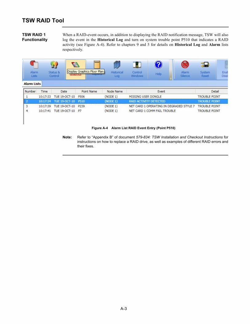
A-3
TSW RAID Tool
TSW RAID 1 Functionality
When a RAID-event occurs, in addition to displaying the RAID notification message, TSW will alsolog the event in the Historical Log and turn on system trouble point P510 that indicates a RAIDactivity (see Figure A-4). Refer to chapters 9 and 5 for details on Historical Log and Alarm listsrespectively.
Figure A-4 Alarm List RAID Event Entry (Point P510)
Note: Refer to “Appendix B” of document 579-834: TSW Installation and Checkout Instructions forinstructions on how to replace a RAID drive, as well as examples of different RAID errors andtheir fixes.


B-1
Appendix B. Annunciation and Control of TFX Points
Introduction This appendix highlights user display and operating characteristics of the TSW that distinguish a TFXsystem from a purely Simplex system.
The TSW supports annunciation and control of TFX points over the TFXnet fire network.The general operation described throughout this document applies to both TFX and Simplex systems.
For example:
1. TFX system device icons and Simplex system device icons can co-exist, and may be potentiallyside by side, on a building-plan/floor-plan graphic screen.
2. A TFX point in an alarm condition causes the TSW’s banner to flash and the TSW’s Active Listand Historical Log to update, just as a Simplex point would. TFX point event can beacknowledged just as a Simplex point event would be and TFX panels can be reset from theTSW, just as Simplex panels would.

B-2
Characteristics Unique to the TFX System
Point Name When displaying a TFX point, the TSW shows a point name that includes:
a. The network number.
b. The node number of the TFX panel on the TFXnet network.
c. TFX-styled point identifier.
Format: <network number>.<node number>:<point identifier>
Following this format, the TFX-styled point name for point 126 on TFX addressable loop A, on TFX panel 1, on the TSW’s network number 2 would be:
2.1:A 126
Note: The network number is shown only if the TSW is monitoring multiple networks.
Isolate / De-Isolate Disabling a TFX point from the TSW causes the point to be “isolated” at the TFX panel.
Enabling a TFX point from the TSW causes the point to be “de-isolated” at the TFX panel.
An isolated (“disabled”) TFX point will show as a trouble at the TSW.
Point Status & Control
Due to the nature of TFXnet operation, only the Enable/Disable control operations are available foruse on TFX points.
Unavailable Features for TFXnet
The Network Topology, the Host Diagnostics, the Test Mode, and the Point Simulate features can notbe used on a TFXnet network.
B-3
Virtual Front Panel
Introduction The TSW’s Virtual Front Panel (VFP) allows you to do status and control operations directly with anindividual TFX panel through the TFXnet.
Establishing a VFP Session from TSW
Important: To establish a VFP session from a TSW, a PC keyboard is required. The VFP does not work with a mouse or a touch-screen.
To connect a VFP session to a TFX Panel, use the TSW Network Tab.
1. Open the Network Tab and use the Select Loop command to select the TFXnet network.The Attendance tab will show available TFX nodes.
2. Double-click on a TFX panel node.The TSW opens the Terminal Mode tab and starts a VFP session with the selected node.
For more details on how to open a session, refer to the “Terminal Mode” section in chapter 11 of thisdocument.
Terminating a VFP Session from TSW
To terminate the session, refer to the “Terminal Mode” section in chapter 11 of this document.
When a VFP Terminal Session terminates remotely (because the TFX panel’s VFP interface timed-out, the TFX panel dropped offline, or for some TFXnet-related problem), the TSW automaticallyends the Terminal Session on its side.
Available keys Once a VFP connection is established, the Terminal window mimics an LCD display of the TFX panel. When in a VFP session, you can only answer to the prompts displayed. To answer, you can use the following keys:
Numbers:- 0 to 9
Letters:- Y for yes (or Enter)- N for no (or Backspace)- Q for quit- A for fast-access.- F for down (forward)- B for up (backup)
Symbols: - Up and down arrows

B-4
Virtual Front Panel
Available Actions The following list is a non-exhaustive list of available actions from the VFP. For details about the available operations at the TFX front panel, refer to the TFX Operator Instructions manual (document 850516):
- View unrestored events- View the log- View the system health report- View system statuses- Set the clock- Test the system- Isolate or de-isolate points- View point or loop data- Force outputs- Set sensitivity- Close the VFP- Print data- Return to the first item- Display time and date- Accept events


© 2009 - 2013 Tyco Fire Protection Products. Specifications and other information shown were current as of publication and are subject to change without notice.
579-835Rev. N