simplex truesite workstation - anz region · includes the truesite workstation runtime application...
TRANSCRIPT

Simplex® TrueSite™ Workstation
Installation &Checkout Instructions
579-834Rev. C

ii
READ AND SAVE THESE INSTRUCTIONS. Follow the instructions in this installation man-ual. These instructions must be followed to avoid damage to this product and associated equipment.Product operation and reliability depends upon proper installation.
DO NOT INSTALL ANY SIMPLEX PRODUCT THAT APPEARS DAMAGED. Uponunpacking your Simplex product, inspect the contents of the carton for shipping damage. If damageis apparent, immediately file a claim with the carrier and notify an authorized Simplex productsupplier.
ELECTRICAL HAZARD - Disconnect electrical field power when making any internaladjustments or repairs. Servicing should be performed by qualified Simplex representatives.
STATIC HAZARD - Static electricity can damage components. Therefore, handle as follows:
• Ground yourself before opening or installing components.
• Prior to installation, keep components wrapped in anti-static material at all times.
EYE SAFETY HAZARD - Under certain fiber optic application conditions, the optical output ofthis device may exceed eye safety limits. Do not use magnification (such as a microscope or otherfocusing equipment) when viewing the output of this device.
RADIO FREQUENCY ENERGY - This equipment generates, uses, and can radiate radio fre-quency energy and if not installed and used in accordance with the instruction manual, may causeinterference to radio communications. It has been tested and found to comply with the limits for aClass A computing device pursuant to Subpart J of Part 15 of FCC Rules, which are designed toprovide reasonable protection against such interference when operated in a commercialenvironment. Operation of this equipment in a residential area may cause interference in whichcase the user at his own expense will be required to take whatever measures may be required to cor-rect the interference.
SYSTEM REACCEPTANCE TEST AFTER SOFTWARE CHANGES - To ensure propersystem operation, this product must be tested in accordance with NFPA-72, after any programmingoperation or change in site-specific software. Reacceptance testing is required after any change,addition or deletion of system components, or after any modification, repair or adjustment to sys-tem hardware or wiring.
All components, circuits, system operations, or software functions known to be affected by achange must be 100% tested. In addition, to ensure that other operations are not inadvertentlyaffected, at least 10% of initiating devices that are not directly affected by the change, up to amaximum of 50 devices, must also be tested and proper system operation verified.
Cautions and Warnings

iii
Copyright and Trademarks
Copyright Tyco Safety Products Westminster, 2007. Tyco, Simplex and the Simplex logo are trade-marks of Tyco International Services AG or its affiliates. All rights reserved. Printed in the UnitedStates of America.
Microsoft® and Windows® are registered trademarks of Microsoft Corporation in the UnitedStates and/or other countries.
Pentium® is a registered trademark of Intel Corporation.
Information in this document is subject to change without notice. No part of this document maybereproduced or transmitted in any form or by any means, electronic or mechanical, for any purpose,without the express written consent of Tyco Safety Products Westminster. Simplex and the Simplexlogo are registered trademarks of Tyco Safety Products Westminster.

iv

Table of Contents
Ch. 1. Before You Begin - - - - - - - - - - - - - - - - - - - - - - - - - - - - - - - - - - - - 1-1
Introduction............................................................................................................................ 1-1Unpack the Equipment .......................................................................................................... 1-1Inventory the Equipment........................................................................................................ 1-1
Ch. 2. Installing the Hardware- - - - - - - - - - - - - - - - - - - - - - - - - - - - - - - - 2-1
Introduction............................................................................................................................ 2-1In this Chapter ....................................................................................................................... 2-1System Requirements for Windows XP Computers .............................................................. 2-2Additional Hardware Requirements (Proprietary and Central Station) .................................. 2-2DACR/TrueSite Workstation Limitations................................................................................ 2-2
System Requirements . . . . . . . . . . . . . . . . . . . . . . . . . . . . . . . . . . . . . . . . . . . . . . . . . . . . 2-2Electrical Input Ratings.......................................................................................................... 2-3Considerations....................................................................................................................... 2-3
System Requirements, Continued . . . . . . . . . . . . . . . . . . . . . . . . . . . . . . . . . . . . . . . . . . 2-4Upgrading Existing Simplex IMS ........................................................................................... 2-4
Connecting the TrueSite Workstation to the System. . . . . . . . . . . . . . . . . . . . . . . . . . . 2-5Connecting the Equipment .................................................................................................... 2-5Connecting a Touchscreen Monitor / Mouse......................................................................... 2-6Connecting the Keyboard ...................................................................................................... 2-7Connecting the Software Key ................................................................................................ 2-7Connecting the Printer (Optional) .......................................................................................... 2-7Connecting the Optional Uninterruptible Power Supply (UPS).............................................. 2-7Connecting to a Network ....................................................................................................... 2-7
Ch. 3. Installing the TrueSite Software - - - - - - - - - - - - - - - - - - - - - - - - - 3-1
Introduction............................................................................................................................ 3-1In this Chapter ....................................................................................................................... 3-1
Software Requirements. . . . . . . . . . . . . . . . . . . . . . . . . . . . . . . . . . . . . . . . . . . . . . . . . . . 3-2TrueSite Workstation Requirements...................................................................................... 3-2Optional Software .................................................................................................................. 3-2
Installing the Software. . . . . . . . . . . . . . . . . . . . . . . . . . . . . . . . . . . . . . . . . . . . . . . . . . . . 3-3Installing Windows XP ........................................................................................................... 3-3Installing Serial Touchscreen ................................................................................................ 3-4Calibrating Touchscreen Software ........................................................................................ 3-5Installing the Optional Tape Drive Software from CD-ROM .................................................. 3-5Editing the Windows WIN.INI file for Optional Tape Drive..................................................... 3-6Installing the Security Service ............................................................................................... 3-6Installing the TrueSite Software............................................................................................. 3-6Requiring or Disabling Logon Password in Workgroup Setting............................................. 3-9

Ch. 4. Installing the TrueSite Workstation Rack-Mount Versions - - - - - 4-1
Introduction............................................................................................................................ 4-1In this Chapter ....................................................................................................................... 4-1
Installing the Rack-Mount Components . . . . . . . . . . . . . . . . . . . . . . . . . . . . . . . . . . . . . 4-2Installation Procedure............................................................................................................ 4-2
Ch. 5. Connecting 2120 Nodes (Retrofit Application Only) - - - - - - - - - - 5-1
Introduction............................................................................................................................ 5-1In this Chapter ....................................................................................................................... 5-1
Installing and Operating the SPC 2120 Utility (Retrofit Application Only) . . . . . . . . . . 5-2Introduction............................................................................................................................ 5-2Installation Procedure............................................................................................................ 5-2Operating the SPC 2120 Utility.............................................................................................. 5-3
Configuring the Computer Ports . . . . . . . . . . . . . . . . . . . . . . . . . . . . . . . . . . . . . . . . . . . 5-4Port Configuration Procedure ................................................................................................ 5-4
Hardware Requirements . . . . . . . . . . . . . . . . . . . . . . . . . . . . . . . . . . . . . . . . . . . . . . . . . . 5-7Required Cables and Connectors ......................................................................................... 5-7
Connecting the 2120 Nodes to the TrueSite Workstation . . . . . . . . . . . . . . . . . . . . . . . 5-8Installing 2120 Nodes ............................................................................................................ 5-8
Adding 2120 Points (Retrofit Application Only) . . . . . . . . . . . . . . . . . . . . . . . . . . . . . . 5-10How to Add 2120 Points to the Point Database and Network ............................................. 5-10
Ch. 6. Connecting DACRs- - - - - - - - - - - - - - - - - - - - - - - - - - - - - - - - - - - 6-1
Introduction............................................................................................................................ 6-1In this Chapter ....................................................................................................................... 6-1
Configuring the TrueSite Workstation to Communicate with DACRs . . . . . . . . . . . . . 6-2Adding the DACR Port........................................................................................................... 6-2Adding DACR Accounts and Points ...................................................................................... 6-2
Connecting DACRs to the TrueSite Workstation . . . . . . . . . . . . . . . . . . . . . . . . . . . . . . 6-3Adding the Event Account ..................................................................................................... 6-3Entering Points Manually....................................................................................................... 6-3Importing CID Points ............................................................................................................. 6-3Installing DACR ..................................................................................................................... 6-4
Connecting DACRs to the TrueSite Workstation, Continued . . . . . . . . . . . . . . . . . . . . 6-7Configuring System III DACR Options................................................................................... 6-7Configuring Bosch D6600 DACR Options ............................................................................. 6-7Configuring AES Intellinet 7705i Receiver Options ............................................................... 6-7

Table of Contents
Ch. 7. Jumpers, Interrupts, and Switch Settings - - - - - - - - - - - - - - - - - - 7-1
Introduction............................................................................................................................ 7-1In this Chapter ....................................................................................................................... 7-1
Interrupt (IRQ) Settings . . . . . . . . . . . . . . . . . . . . . . . . . . . . . . . . . . . . . . . . . . . . . . . . . . . 7-2Recommended Interrupt (IRQ) Settings ................................................................................ 7-2TrueSite Workstation IRQ Settings........................................................................................ 7-2Possible IRQ Settings............................................................................................................ 7-3
Jumper Settings. . . . . . . . . . . . . . . . . . . . . . . . . . . . . . . . . . . . . . . . . . . . . . . . . . . . . . . . . 7-4RS232 Media Card (P/N 565-327) ........................................................................................ 7-4Wired Media Card (P/N 565-413) .......................................................................................... 7-4Fiber Optic Media Assembly.................................................................................................. 7-4
Switch Settings . . . . . . . . . . . . . . . . . . . . . . . . . . . . . . . . . . . . . . . . . . . . . . . . . . . . . . . . . 7-5UL I/O Card (P/N 565-283).................................................................................................... 7-5
Configuring the Devices . . . . . . . . . . . . . . . . . . . . . . . . . . . . . . . . . . . . . . . . . . . . . . . . . . 7-6Configuring Device Drivers for Windows XP ......................................................................... 7-6Quad Serial Port Card ........................................................................................................... 7-6
Interfacing with the Simplex Fire Network . . . . . . . . . . . . . . . . . . . . . . . . . . . . . . . . . . . 7-7Network Interface Card.......................................................................................................... 7-7Network Interface Card Installation Sequence ...................................................................... 7-8
Installing Cards and Jumpers. . . . . . . . . . . . . . . . . . . . . . . . . . . . . . . . . . . . . . . . . . . . . . 7-9Inserting and Connecting Cards in the TrueSite Workstation................................................ 7-94190-8403 - Card Slot Positions............................................................................................ 7-9Continuity Check for Model 4190-8403 with UL I/O Card Installed ..................................... 7-10Verifying Tape Drive Installation.......................................................................................... 7-10Reboot Watchdog................................................................................................................ 7-10
Installing the Second Video Card. . . . . . . . . . . . . . . . . . . . . . . . . . . . . . . . . . . . . . . . . . 7-11Installation Procedure.......................................................................................................... 7-11
Disabling the Reboot Watchdog. . . . . . . . . . . . . . . . . . . . . . . . . . . . . . . . . . . . . . . . . . . 7-14Reboot Watchdog................................................................................................................ 7-14
Ch. 8. Simplex 4190 TrueSite Workstation Checkout - - - - - - - - - - - - - - 8-1
Introduction............................................................................................................................ 8-1In this Chapter ....................................................................................................................... 8-1
Simplex 4190 TrueSite Workstation Checkout . . . . . . . . . . . . . . . . . . . . . . . . . . . . . . . . 8-2How to Checkout the TrueSite Workstation........................................................................... 8-2Testing Circuit Supervision.................................................................................................... 8-2


1-1
Chapter 1. Before You Begin
Introduction This publication describes how to install and check out the Simplex® TrueSite™ Workstation, whichincludes the TrueSite Workstation Runtime application and the TrueSite Workstation Configurator.
The TrueSite Workstation Runtime application provides head-end annunciation, floor plan display,system control and information management for Simplex fire system networks. The TrueSiteWorkstation is a node on a Simplex Fire Network used to annunciate and control the points containedwithin the network. If you are installing additional Network Interface Cards, you can control up tofour networks from one common TrueSite Workstation. The TrueSite Runtime application providedis a Microsoft Windows® XP application that makes it easy to interact with the network by enteringinput through a keyboard, mouse, or touchscreen.
The TrueSite Workstation Configurator is a programming application used to configure hardwaredevices, network nodes, and general system settings in the TrueSite Workstation.
Unpack the Equipment
When you receive the equipment, immediately inspect the packaging for any signs of shippingdamage. If there are any signs of shipping damage, file a claim with the carrier and notify your localSimplex product supplier.
If there are no signs of shipping damage to the packaging, proceed with unpacking the equipment.Remove all protective plastic covering, styrofoam packaging material, and any other packagingmaterial that may have been used.
Inventory the Equipment
After the equipment is unpacked, locate the shipping papers that came with the equipment andinventory the equipment received. If equipment is missing, notify your local Simplex productsupplier. If you received all the equipment listed on the shipping papers, proceed with the hardwareinstallation.


2-1
Chapter 2. Installing the Hardware
Introduction This chapter describes the necessary TrueSite Workstation hardware and shows you how to successfully install the TrueSite Workstation Runtime application and TrueSite Workstation Configurator.
In this Chapter This chapter discusses the topics listed in the following table. Refer to the page number listed after the topic for information on that topic.
Topic See Page #
System Requirements 2-2
Connecting the TrueSite Workstation to the System 2-5

2-2
System Requirements for Windows XP Computers
For a Microsoft® Windows® XP-based computer platform to operate properly as a TrueSiteWorkstation, it must meet or exceed the following minimum hardware requirements:
• An IBM-compatible personal computer with a Pentium® 4 (2.8 Ghz minimum) Processor • 40 GB (or greater) Hard Drive• USB Port (for Dongle)• 1 GB of RAM minimum• SVGA graphics controller• SVGA Monitor (with or without touchscreen)• Mouse• CD drive (CD-RW recommended)• Fan monitor card (required for 4190-8403)
The following is a list optional requirements based on the necessity of additional devices:
• 1 parallel port (for printer)• 2 serial ports (for connecting DACR and 2120 retrofit)
Additional Hardware Requirements (Proprietary and Central Station)
NFPA-72 proprietary receiving and Central Station applications require the following additional equipment:
• A Simplex printer that is a UL-listed control unit accessory (4190-9013).• A Sur-Gard System III DACR, Bosch D6600 DACR or AES Intellinet 7705i Receiver with
Installation Manual, for Central Station Applications only.
DACR/TrueSite Workstation Limitations
The DACR supports the following protocol formats in the TrueSite Workstation:
• Ademco CID • 3/1*• 4-2*• BFSK• SIA level 1
Note: AES only supports Ademco CID
The TrueSite Workstation does not support the B32 Header option for TCP/IP messages. The TCP/IP for the DACR works with the configured TrueSite Workstation default settings. The TrueSite Workstation is able to receive messages from the DACR.
* Protocols are only available for security applications and signalling.
System Requirements
2-3
System Requirements, Continued
Electrical Input Ratings
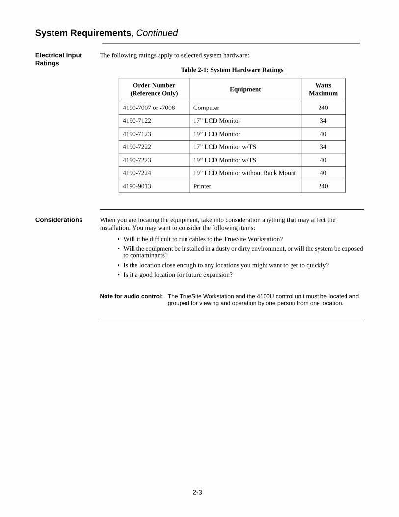
The following ratings apply to selected system hardware:
Considerations When you are locating the equipment, take into consideration anything that may affect the installation. You may want to consider the following items:
• Will it be difficult to run cables to the TrueSite Workstation?• Will the equipment be installed in a dusty or dirty environment, or will the system be exposed
to contaminants?• Is the location close enough to any locations you might want to get to quickly?• Is it a good location for future expansion?
Note for audio control: The TrueSite Workstation and the 4100U control unit must be located and grouped for viewing and operation by one person from one location.
Table 2-1: System Hardware Ratings
Order Number (Reference Only) Equipment Watts
Maximum
4190-7007 or -7008 Computer 240
4190-7122 17” LCD Monitor 34
4190-7123 19” LCD Monitor 40
4190-7222 17” LCD Monitor w/TS 34
4190-7223 19” LCD Monitor w/TS 40
4190-7224 19” LCD Monitor without Rack Mount 40
4190-9013 Printer 240

2-4
System Requirements, Continued
Upgrading Existing Simplex IMS
Note: This section is only relevant if you are upgrading a Simplex IMS using a UL864 Listed PC to run the TrueSite Workstation Runtime application and TrueSite Workstation Configurator. Otherwise, if your Simplex UL864 Listed PC is up to date with the manufacturing implementation of new PC specifications, ignore the following instructions.
The Information Management System (IMS) requires and additional 512MB DIMM RAM module inorder to run the TrueSite Workstation Runtime and Configurator applications. The appropriatehardware upgrades (4190-9812) and software upgrades (4190-9812) must be performed. The totalamount of RAM required by TrueSite Workstations is 1GB.
To install the additional 512MB DIMM RAM, follow this procedure:
1. Backup the system and notify all building personnel and occupants that the IMS is going offline until system upgrade is completed.
2. Shut down the Simplex UL864 Listed PC.3. Disable the power supply by pushing switch situated at the back of its case.4. Strip off the case of the tower by doing the following:
a. Remove the screws in the back of the unit. Keep them in a bag or a container to avoid losing them.
b. Once the screws are removed, slide the case forward.c. Lift up the case to expose the components inside the PC tower.
4. Locate the Single Board Computer (SBC) in the second slot.5. The RAM slots are situated on top of the board. Normally, there is a DIMM unit in the top slot.6. Install the RAM:
a. Make a note of how the existing unit looks.b. Locate the little notches on the pin-side of the module. These notches (usually two) are lined
up with keys on the memory socket itself to ensure proper alignment.c. Place the module over the slot and press it in with the ejector clips in the open position. You
must apply pressure and also support the back side of the SBC. As you press down, the module will sink into place and the ejector clips will close themselves to lock the module into place.
4. Before you put the case back on, make sure that the amount of RAM tallies properly.a. Enable the power supply and start the system.b. After starting the system, select Start -> Control Panel. This brings up the Control Panel
folder.c. From the Control Panel folder, double-click the System icon.d. The System Properties dialog appears. Verify the RAM capacity of the system under the
General tab.5. After verifying that the new RAM amount, shut down the Simplex UL864 Listed PC.6. Put the case back on and secure it with the screws.7. Start the Simplex UL864 Listed PC.

2-5
Connecting the TrueSite Workstation to the System
Connecting the Equipment
Note: Be advised that the procedures described in this section are specific to the Simplex UL864 Listed PC.
After choosing the location for the equipment, you are ready to connect the equipment in preparation for the installation of the TrueSite software.
Note: If you need to install additional cards into the TrueSite Workstation, or modify existing card settings, please do so before connecting the equipment. One example is when you need to install PCI cards for a multiple-loop network.
To install the hardware, place the PC in the desired location and connect the equipment you will use with the system (printer, mouse, etc.). A typical TrueSite Workstation hardware configuration is shown in Figure 2-1.
Note: Verify that all the PC boards are firmly seated into the motherboard. This helps ensure that you have complete electrical connections.
The TrueSite Workstation rack-mount monitor is shown in Chapter 4.
Figure 2-1 Example of Typical TrueSite Workstation System Configuration on a Simplex UL864 Listed PC, Block Diagram
Continued on next page

2-6
Connecting the TrueSite Workstation to the System, Continued
Connecting the Equipment, Continued
WARNING: Do not plug the keyboard or keyboard adapter into a powered unit! This will damage the CPU board. All equipment must be powered down before adding any hardware.As you connect the equipment, refer to the figures below and the instructions that follow.
Figure 2-2 Simplex UL864 Listed PC Rear Panel Layout – 2.8 Ghz or Faster System using PCI Network Cards (Windows XP Platform)
Connecting a Touchscreen Monitor / Mouse
To connect a touchscreen monitor, position the monitor close enough to the PC so that you can connect the cables from the monitor to the PC and perform the following steps:1. Connect the touchscreen controller cable to PC Serial Port, Com1 or Com2 is preferred.2. Connect the other end of the cable to the touchscreen input connector on the back of the monitor.
To connect the mouse do the following:1. Locate the mouse/keyboard connector on the back of the PC.2. Plug the connector on the end of the mouse cable into the mouse/keyboard adapter cable on the
PC.

2-7
Connecting the TrueSite Workstation to the System, Continued
Connecting the Keyboard
Connect the keyboard by completing the following steps:1. Locate the mouse/keyboard connector on the back of the PC.2. Plug the connector on the end of the keyboard cable into mouse/keyboard adapter cable on the PC.
Connecting the Software Key
You need to have either a USB software key or a parallel dongle key.• Connect the USB software key by inserting it into the USB port,• Or, connect the parallel dongle key by inserting it into the parallel port.
Note: THIS SHOULD BE DONE AFTER THE SECURITY SERVICE SOFTWARE IS INSTALLED ON THE PC.
For instructions on installing the Security Service, refer to Installing the Software Security System, 579-825.
Connecting the Printer (Optional)
Connect the printer by performing the following steps:1. Locate the serial Com port on the PC that was selected in the program.2. Plug harness 733-937 into the printer and complete the connections per 4190-9013 Remote Printer
Installation Instructions, 579-233.
Note: These instructions are specific for connecting a serial port printer. To connect a parallel port printer, use a standard parallel port cable.
Connecting the Optional Uninterruptible Power Supply (UPS)
Note: A UPS (La Marche Series A-31 and A-36D) is required only for proprietary receiving station applications.
Connect the Uninterruptible Power Supply (UPS) by completing the following steps:1. Plug the PC, printer, and monitor power cords into the AC outlet, which is integral to the
equipment rack.2. Connect the dedicated branch circuit to the AC power input of the UPS.3. Connect the output of the UPS (in conduit) to the AC input terminals provided on the equipment
rack.4. Connect the transfer contacts of the UPS to the first of the general-purpose I/O points on the UL
I/O card (see diagram 841-947 for interconnection specifics).
Connecting to a Network
Complete the following steps for each network interface card you are installing. You can install up to four network interface cards in a TrueSite Workstation.1. Locate the network interface card on the back of the PC.2. Connect the cable from the previous node’s right port to the top connector on the network card.3. Connect the next node’s left port to the bottom connector on the network card.


3-1
Chapter 3. Installing the TrueSite Software
Introduction This chapter describes how to install the TrueSite Workstation software, which include the TrueSiteWorkstation Runtime application and the TrueSite Workstation Configurator.
In this Chapter This chapter discusses the topics listed in the following table. Refer to the page number listed after thetopic for information on that topic.
Topic See Page #
Software Requirements 3-2
Installing the Software 3-3

3-2
Software Requirements
TrueSite Workstation Requirements
The following software is required for adequate TrueSite Workstation operation. In some instances,this software may have already been installed:
• Windows® XP operating system• Required software drivers (mouse, touchscreen, or printer drivers)
Optional Software The following software may also be needed:
• 3M (Touchware)Touchscreen Controller Software Version 5.64 SR6 or later (the disk is included with the touchscreen)
• Microsoft Intellipoint for the Microsoft Mouse, latest version• IOMEGA Tape Drive Software drivers disk (required if you are installing a TrueSite
Workstation tape drive in the field)

3-3
Installing the Software
Installing Windows XP
If Windows XP operating system software must be installed on your computer, follow theinstructions given in the Microsoft documentation for this product. After the Windows XP operatingsystem has been installed, modify the computer for TrueSite Workstation operation in the followingmanner.
BIOS Setup:Modify the BIOS Setup as follows:1. During initialization, enter the BIOS SETUP by pressing the DEL key.2. Select PNP/PCI Configuration.3. Change IRQ 11 from PCI/ISA PnP to Reserved.4. Select Power Management. Change ACPI Function to disabled.5. Press <ESC>, “Save Changes and Exit.”
Display:Set the Display options as follows:1. Click on the Start button and select Settings, then the Control Panel menu.2. Double-Click the Display icon.3. Under the Settings tab, set the “Desktop Area” to 1024 by 768 or greater and 32 Bit True color.
Click on Apply. Windows shows a test view of the new settings. If the new setting is accurate, click on Accept Changes.
4. Under the Screen Saver tab, set the Screen Saver selection to (None). (Alarm messages on the computer screen can not be seen when the Screen Saver is running)

3-4
Installing the Software, Continued
Installing Serial Touchscreen
This section describes the installation of the Serial Touchscreen software (driver) for Windows XP.1. Connect the two cables from the Serial Touchscreen monitor to the PC.
a. Connect one cable to the connector labelled Video.b. Connect the other cable to the serial connector, COM1 or COM2 is preferred.
2. Check all other cables to ensure that they are secure.3. Connect the AC power cord from the monitor to an AC source.4. Turn on power to the PC and monitor.5. Locate the disk that contains the serial touchscreen drivers and insert it into the PC drive.6. From the Windows START icon, select RUN and BROWSE.
a. Go to the correct drive and select setup.exe.7. Follow the instructions and select the correct COM number. If the touchscreen is connected, it will
auto-detect.8. Follow the directions on the screen. When calibrating, look for the red bull’s eye in the center of
the screen.

3-5
Installing the Software, Continued
Calibrating Touchscreen Software
This section describes how to calibrate Touchscreen software in Windows XP.1. Click the Start button to invoke the Windows XP system menu, and choose Settings, then
Control Panel.2. Double-click Touchware to run the Touchscreen Control Panel.3. Click the Align button and touch each of the three targets as they appear on the screen. Click Yes
when the cursor lines up correctly with your finger.4. Click OK to close the Touchscreen Control Panel.
Installing the Optional Tape Drive Software from CD-ROM
Note: Tape drives are not supported in the Run-time software.
1. Insert the IOMEGA CD into the computer CD Rom drive.2. Select the Install icon.3. Follow the prompts on the screen.
Table 3-1: Tape Drive Software Installation Settings
Field Setting/Action
Screen Selection Color
Backup Install Accept Default
Personalize your Company Your NameYour Company
Tape Configuration Start Test
Tape Configure OK
Alert Insert Tape and select Con-tinue Backup
Compare Complete OK
Compatibility Test Successful OK
Configuration Test OK
Backup AUTOSTART NO
Update AUTOEXEC.BAT OK
Update AUTOEXEC.BAT modifications
Save Changes
Update CONFIG.SYS OK
Configure Save
Backup Install Reboot

3-6
Installing the Software, Continued
Editing the Windows WIN.INI file for Optional Tape Drive
Modify the WIN.INI file as follows:1. Click on the Start button and select Programs, then Command Prompt.2. At the C:\WINDOWS> prompt, type EDIT WIN.INI and press ENTER. The WIN.INI
(Windows Initialization) file is displayed on the text editor screen.3. Scroll to the line reading “Run=C:\QBWIN\DITTO.EXE.”4. Place a semi-colon (;) at the beginning of this line. This prevents the command from executing
when Windows starts.
Installing the Security Service
Please refer to Installing the Software Security System, 579-825, for instructions on installing the KeySecurity Service. This service is necessary for access to the program.
Note: The publication Installing the Software Security System, 579-825 ships with the TrueSite Workstation.
Installing the TrueSite Software
Notes: • Before installing the TrueSite software, make sure that Windows XP is installed.
• You should install the new Network Programmer with TrueSite Workstation node support to configure the network. Refer to Simplex Fire Network Programmer Installation and Pro-gramming Instructions, 579-166 for details on how to program the network.
The TrueSite Workstation CD contains a package with the following applications:• TrueSite Workstation Runtime application• TrueSite Workstation Configurator
The TrueSite Workstation is easy to install and requires less than 20 MB of free disk space on thetarget system. Minimum space requirements are automatically verified during installation and theinstallation process is terminated if the minimum system requirements are not met.
To install the TrueSite Workstation applications, complete the following steps:1. Insert CD into the CD drive. In the case that the installation process does not start by itself do the
following:a. From the Windows XP Start menu, select Run. The system displays a command line dialog
box.b. On the command line, type D:\truesiteworkstation.exe (where D: is the CD drive letter)
and select OK. The system displays the message Install Shield dialog box.
Continued on next page

3-7
Installing the Software, Continued
Installing the TrueSite Software, Continued
2. Follow the on-screen instruction to install the TrueSite software.
Note: Whenever available, you may click on the Back button to review and make changes to your selections from the previous dialogs, or click on the Cancel button to terminate the installation process before it completes.
a. As the installation process initializes, a Setup Preparation dialog appears followed by a wel-come dialog. To proceed with the installation, click Next.
b. An End-User License Agreement (EULA) Dialog appears as shown in Figure 3-1. You must scroll down and read through the agreement.
• If you agree with the terms of the EULA, check the radio button next to “I accept the terms of the license agreement”, then click Next to proceed with the installation.
• If you do not accept with the terms of the EULA, check the “I do not accept the terms of the license agreement” radio button and click Next to terminate the installation process immediately.
Figure 3-1 End-User License Agreement Dialog
c. Once you’ve confirmed your agreement to the EULA, a Customer Information dialog prompts you to enter your username and company name as shown in Figure 3-1. Provide the required information and click Next.
d. Enter the User Name and Company Name in the appropriate fields of the Customer Information screen (see Figure 3-1) and then click Next to continue.
Figure 3-2 Customer Information Dialog
Continued on next page

3-8
Installing the Software, Continued
Installing the TrueSite Software, Continued
e. The Program File Review dialog appears. This dialog allows you to review the programs files that are about to be copied. To proceed to the next step of the installation, click Next.
f. A Ready to Install dialog appears. To proceed with the installation, click Install.g. While TrueSite Workstation applications are installing on the PC, a Setup Status dialog
displays the installation progress.h. TrueSite installation is complete, the InstallShield Wizard Complete dialog appears as
shown in Figure 3-3. Click Finish.
Figure 3-3 InstallShield Wizard Complete Dialog
3. Remove the CD from the drive and store it in a safe place for future use.4. To automatically start TrueSite Workstation immediately after system reboot, place a TrueSite
Workstation shortcut in the Startup folder for All Users.
Note: To prevent the TrueSite Workstation from starting, hold down the shift key when starting Windows.

3-9
Installing the Software, Continued
Requiring or Disabling Logon Password in Workgroup Setting
To require or disable a logon password in a workgroup setting:1. Click Start, and then click Run.2. On the Open box, type control userpasswords2 and click OK:
• Click the Users must enter a user name and password to use this computer check box to require users to provide this information when they log on.
• Clear the Users must enter a user name and password to use this computer check box to allow a user to automatically log on. You will be prompted to provide the name and password of the users who will be automatically logged on each time the computer starts.
Notes: • The Users must enter a user name and password to use this computer check box only appears if your computer is not connected to a network domain.
• UL listed TrueSite Workstation cannot be connected to any TCP/IP network. The previous note does not apply to UL listed workstations.
• You must be logged on as an administrator or a member of the Administrators group to make the modifications stated above.
• Requiring users to enter a name and password provides secure protection for your com-puter. Windows XP verifies each account and provides access to the computer only if the information is correct.
• If only one person uses the computer or the security risk is low, you might find it conve-nient to allow Windows XP to automatically log on each time that you start the computer.
Important: To meet the proprietary receiving station requirement, you must adhere to the Important note at the top of this page.


4-1
Chapter 4. Installing the TrueSite Worksta-tion Rack-Mount Versions
Introduction The TrueSite Workstation is available as a rack-mount.
In this Chapter This chapter discusses the topics listed in the following table. Refer to the page number listed after thetopic for information on that topic.
Topic See Page #
Installing the Rack-Mount Components 4-2

4-2
Installing the Rack-Mount Components
Installation Procedure
The entire rack set-up is assembled and tested at the factory. After testing is completed, the PC and monitor are removed and packed in their original shipping cartons. The rails and any other additional items are left on the PC and monitor. The rack is then shipped as an assembled unit.
Complete the following steps to install the remaining components:1. Secure the rack to the floor.2. Separate the conduits for the entry of power-limited and non-power limited supply lines through
the bottom plate (there is a label on the bottom plate showing the desired location for these supply lines).
3. Install the PC in the rack (the rails are already assembled) and secure it with 10-32 screws (supplied).
4. Plug the monitor power cord into the PC power outlet.5. Plug the PC power cord into the surge protector.6. Secure the power wires to the back left rail using the tie wrap provided (leave a minimum service
loop for sliding of the PC).7. Secure all other wires (non-power limited) to the back right rail using the tie wrap provided.8. Connect the incoming AC line to the AC termination block.9. After you have set up the Rack-Mount TrueSite Workstation, you can continue installing it on the
network.
Continued on next page

4-3
Installing the Rack-Mount Components, Continued
Installation Procedure, Continued
Figure 4-1 Rack-Mount Installation


5-1
Chapter 5. Connecting 2120 Nodes (Retrofit Application Only)
Introduction This chapter describes how to connect 2120 nodes to a TrueSite Workstation using the existingRS232 Serial Port.
Note: Keep in mind that 2120 is Retrofit only. To connect 2120 nodes using the Multiport card, refer to the SLI Multiport Option - Installation Instructions, 574-097.
In this Chapter This chapter discusses the topics listed in the following table. Refer to the page number listed after thetopic for information on that topic.
Topic See Page #
Installing and Operating the SPC 2120 Utility (Retrofit Application Only)
5-2
Configuring the Computer Ports 5-4
Hardware Requirements 5-7
Connecting the 2120 Nodes to the TrueSite Workstation 5-8
Adding 2120 Points (Retrofit Application Only) 5-10

5-2
Installing and Operating the SPC 2120 Utility (Retrofit Application Only)
Introduction Note: Disregard this section if you do not have a 2120 interface.
This section describes the necessary steps to install and configure the 2120 Serial Point CollectionUtility (SPC 2120).
For further information, consult publication Multiport SLI Option Installation Instructions, 574-097.
Installation Procedure
Use the following procedure to install the SPC 2120:1. Insert the installation media into the appropriate drive. If you are using a Windows XP Operating
System, open an MS-DOS command window by selecting the Start button, then the all Programs menu choice. Choose Accessories and then Command Prompt from the Program menu.
2. From the C:\ or C:\WINDOWS prompt type [drive name]:install and press Enter.3. From the installation screen, select I to install the SPC 2120 or E to exit the installation. 4. The SPC 2120 installation program then asks you where you wish the utility installed. The typical
installation is installed in the C:\SPC2120 directory.5. After a successful installation, the SPC 2120 installation program returns you to the DOS prompt.

5-3
Installing and Operating the SPC 2120 Utility, Continued
Operating the SPC 2120 Utility
Note: A serial cable must be connected from COM X of the PC to a 2120 Computer Port prior to running the SPC 2120 Utility.
To run the SPC 2120 Utility, type SPC2120 [/option] from the C:\SPC2120 directory. TypingSPC2120 without a specified option assumes a complete download from Port 1. The options are listedbelow.• /A - Complete Download• /L - Update Custom Labels• /P - Update Priorities• /S - Update Suppressions• /Nn - Port number; n = the port number (only used as a file reference)• /H or /? - Shows list of parameters (help)
In order to perform the updating options (/L, /P, or /S), a matching 2120_N.SLI (where “N” is thenumber of the 2120 node) file must already exist. When doing these updates, the point information isreferenced from the existing 2120_N.SLI file. Then the specified update request information (/L, /P,or /S) is received from the 2120 and compared to the existing information before writing a new file.When doing a Complete Download, all information is received from the 2120. In both cases, theoriginal file is backed up to 2120_N.SAV. If this file already exists, the program prompts you to entera filename.
Once the SPC 2120 command is entered, the program asks you for a job name. You can type up toeight characters for a job name and press Enter. The SPC 2120 informs you when the systemcompletes a successful download.
Before copying the SPC 2120 output file into the TrueSite Workstation/NPU directory structure,rename it from “2120IOn.SLI” to the 2120 CMS file number without the revision letter. Forexample, if the CMS file number is “W123456A”, then rename the file from “2120IOn.SLI” to“W123456.SLI”. Before an update option /L, /P, or /S can be performed, the file must be renamedback to “2120IOn.SLI” for the SPC 2120 program to find an existing comparison file.
Notes: • CMS stands for “Conversational Monitor System” which is a simple single-user operat-ing system from IBM’s VM family. IBM mainframe computers that are used to program the 2120 usually run on the CMS operating system.
• By default, the CMS number is the job name that is printed on the very first page of every 2120 program report.
Before starting the SPC 2120 program, make sure all points to be copied to the TrueSite Workstationare vectored to the download port. Only the points vectored to the 2120 download port will be copiedto the output file.
Notes: • Print class 1 points are vectored to all ports and print class 0 points are not vectored to any ports. Points that were print class 0 and do not need to be printed at the 2120 strip printer should be changed to print class 7 and then vectored to the download port.
• When running the SPC 2120 program, the PC should be connected to the port on the 2120 that will be connected to the TrueSite Workstation at runtime.
5-4
Configuring the Computer Ports
Port Configuration Procedure
Use the TrueSite Workstation Configurator and the following steps to configure the RS232 ports tocommunicate with the 2120.
Note: All required hardware and software (e.g., controllers, drivers, etc.) must be installed before you can successfully complete the following configuration.
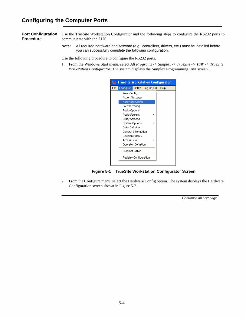
Use the following procedure to configure the RS232 ports.1. From the Windows Start menu, select All Programs -> Simplex -> TrueSite -> TSW -> TrueSite
Workstation Configurator. The system displays the Simplex Programming Unit screen.
Figure 5-1 TrueSite Workstation Configurator Screen
2. From the Configure menu, select the Hardware Config option. The system displays the Hardware Configuration screen shown in Figure 5-2.
Continued on next page

5-5
Configuring the Computer Ports, Continued
Port Configuration Procedure, Continued
Figure 5-2 TrueSite Workstation Configurator Hardware Configuration Screen
3. Check the current hardware settings. To change a specific hardware setting, highlight the setting with your mouse and double click or use the Up and Down arrow keys to highlight the setting you wish to change and press F2. The system displays the Add Run-Time Hardware dialog shown in Figure 5-3.
Figure 5-3 Add Run-Time Hardware Dialog
Continued on next page
5-6
Configuring the Computer Ports, Continued
Port Configuration Procedure, Continued
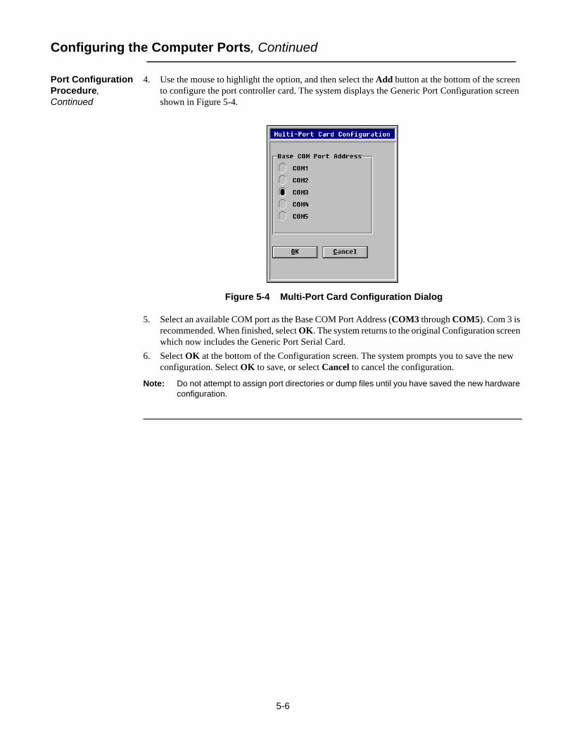
4. Use the mouse to highlight the option, and then select the Add button at the bottom of the screen to configure the port controller card. The system displays the Generic Port Configuration screen shown in Figure 5-4.
Figure 5-4 Multi-Port Card Configuration Dialog
5. Select an available COM port as the Base COM Port Address (COM3 through COM5). Com 3 is recommended. When finished, select OK. The system returns to the original Configuration screen which now includes the Generic Port Serial Card.
6. Select OK at the bottom of the Configuration screen. The system prompts you to save the new configuration. Select OK to save, or select Cancel to cancel the configuration.
Note: Do not attempt to assign port directories or dump files until you have saved the new hardware configuration.

5-7
Hardware Requirements
Required Cables and Connectors
Table 5-1 lists the required cable and connectors to complete the installation. Figure 5-5 shows adiagram of how to connect the cables and connectors from the RS232 port on each 2120 node to theRS232 connector on the CPU.
*If the RS232 ports on the TrueSite Workstation are DB25 male connectors, this adapter is notneeded.
Table 5-1: Cables and Connectors for TrueSite Workstation Installation
Part Number Description
617-836* 6-foot (2 m) DB9 to DB25 adapter cable
733-571 Harness assembly (receptacle suppressor)
733-572 Harness Assembly (RS232 suppressor)

5-8
Connecting the 2120 Nodes to the TrueSite Workstation
Installing 2120 Nodes
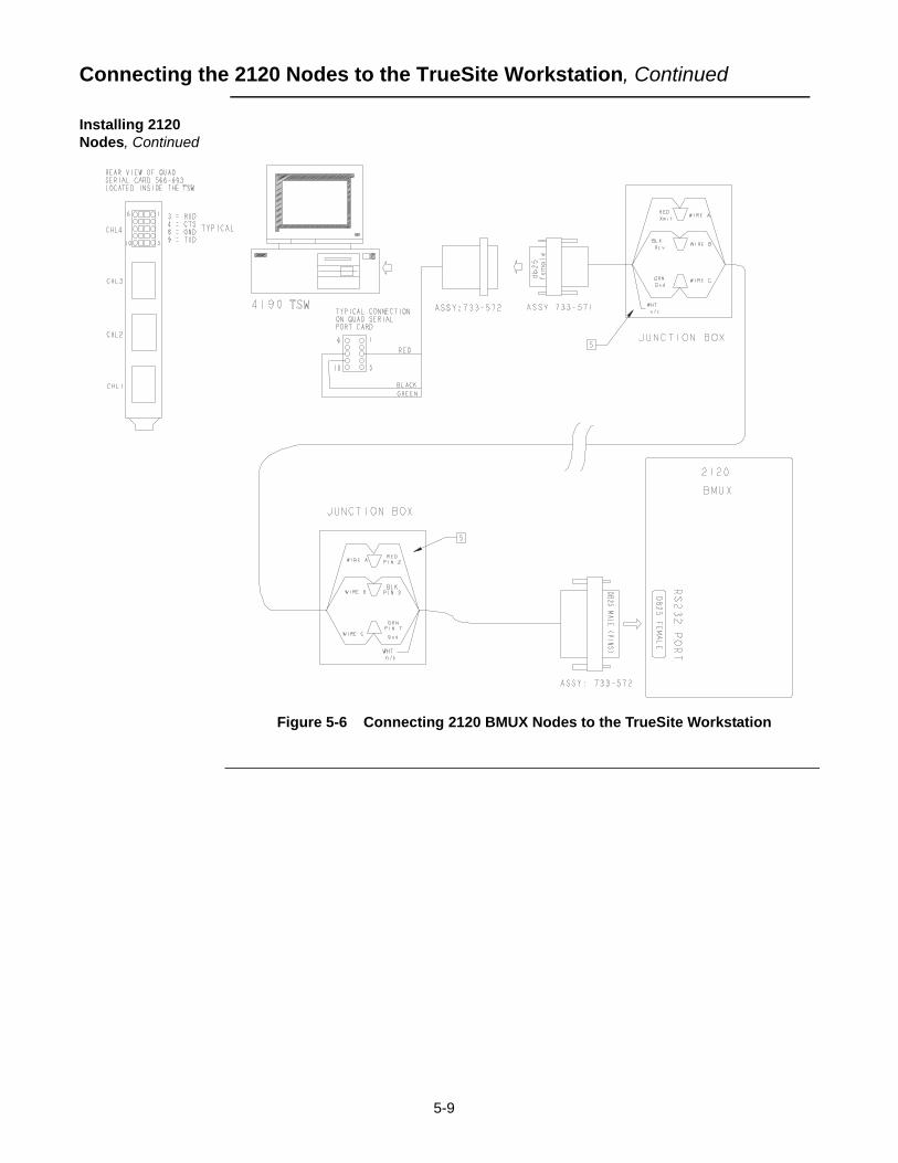
To connect the 2120 nodes to the TrueSite Workstation, complete the following steps.
Note: Ensure that the power is OFF before starting this procedure.
1. Complete all wiring according to the wiring diagram.
Notes: • If you are connecting the 2120 to the TrueSite Workstation with an adapter cable (using DB9 connector), refer to the diagram in Figure 5-5 for detail.
• If you are connecting the 2120 to the TrueSite Workstation without an adapter cable (using DB25 connector), refer to the diagram in Figure 5-6 for detail.
2. Use the junction boxes at each end of the installed cable to terminate the field wiring between harness 733-571 and 733-572.
3. After connecting the node(s) to the TrueSite Workstation, turn the power ON. The TrueSite Workstation automatically boots up to the initial program screen.
Figure 5-5 Connecting 2120 Nodes to the TrueSite Workstation
Continued on next page
5-9
Connecting the 2120 Nodes to the TrueSite Workstation, Continued
Installing 2120 Nodes, Continued
Figure 5-6 Connecting 2120 BMUX Nodes to the TrueSite Workstation

5-10
Adding 2120 Points (Retrofit Application Only)
How to Add 2120 Points to the Point Database and Network
Complete the following steps to add 2120 points to the network and to the point database.1. Use Windows Explorer or File Manager to select the following directory: \netjobs\tst2120\n72. In Windows XP Explorer select New, then Folder from the File menu.3. Name the new Folder or Directory 2120_1 for Port 1, or 2120_2 for Port 2.
Notes: • Before copying the SPC2120 output file into the TrueSite Workstation/NPU directory struc-ture, rename it from “2120IOn.SLI” to the 2120 CMS file number without the revision letter. For example, if the CMS file number is “W123456A”, then rename the file from “2120IOn.SLI” to “W123456.SLI”.
• The TrueSite Workstation scans the new directory for a .SLI file. The TrueSite Workstation learns this file name only once. Do not change the name after the directory has been scanned.
4. Copy the 2120 dump file to the new directory. The file extension must be .SLI in order for the TrueSite Workstation Configurator software to accept it.
5. Return to the Start menu and select the TrueSite Workstation Configurator icon. The system is now aware of the new port configurations and has automatically added certain system, channel and transponder information into the hardware configuration.
6. Select View from the Point Configuration screen and scroll past Point No. 52815 to display this information.
7. From the TrueSite Workstation Configurator screen, select the Configure menu and select the Point Config option. The system displays the 2120 Port Selection dialog shown in Figure 5-7.
Figure 5-7 2120 Port Selection Screen
Continued on next page
5-11
Adding 2120 Points (Retrofit Application Only), Continued
How to Add 2120 Points to the Point Database and Network, Continued
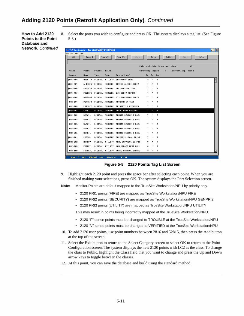
8. Select the ports you wish to configure and press OK. The system displays a tag list. (See Figure 5-8.)
Figure 5-8 2120 Points Tag List Screen
9. Highlight each 2120 point and press the space bar after selecting each point. When you are finished making your selections, press OK. The system displays the Port Selection screen.
Note: Monitor Points are default mapped to the TrueSite Workstation/NPU by priority only.
• 2120 PRI1 points (FIRE) are mapped as TrueSite Workstation/NPU FIRE
• 2120 PRI2 points (SECURITY) are mapped as TrueSite Workstation/NPU GENPRI2
• 2120 PRI3 points (UTILITY) are mapped as TrueSite Workstation/NPU UTILITY
This may result in points being incorrectly mapped at the TrueSite Workstation/NPU.
• 2120 “F” sense points must be changed to TROUBLE at the TrueSite Workstation/NPU
• 2120 “V” sense points must be changed to VERIFIED at the TrueSite Workstation/NPU
10. To add 2120 user points, use point numbers between 2816 and 52815, then press the Add button at the top of the screen.
11. Select the Exit button to return to the Select Category screen or select OK to return to the Point Configuration screen. The system displays the new 2120 points with LC2 as the class. To change the class to Public, highlight the Class field that you want to change and press the Up and Down arrow keys to toggle between the classes.
12. At this point, you can save the database and build using the standard method.


6-1
Chapter 6. Connecting DACRs
Introduction This chapter describes how to connect DACRs (Digital Alarm Communicator Receivers) to anTrueSite Workstation using the existing RS232 Serial Port. The three DACR models that aresupported are the Sur-Gard System III DACR, the Bosch D6600 DACR and the AES Intellinet 7705iReceiver.
In this Chapter This chapter discusses the topics listed in the following table. Refer to the page number listed after thetopic for information on that topic.
Topic See Page #
Configuring the TrueSite Workstation to Communicate with DACRs 6-2
Connecting DACRs to the TrueSite Workstation 6-3

6-2
Configuring the TrueSite Workstation to Communicate with DACRs
Adding the DACR Port
You must configure the TrueSite Workstation to communicate with the DACR. To start, you need addthe DACR port. To do so, you:1. Select the hardware configuration item from the Configuration Menu.2. Hit the Add Button.3. Select DACR Port.4. In the DACR Port dialog box, select the COM port that is connected to the DACR.
Note: Refer to page 6-7 for details on the other fields in the DACR port dialog (depending on which model is used).
5. Select OK before saving and exiting the Hardware Configuration Screen.
Adding DACR Accounts and Points
Next, you need to add accounts and points. To do so, you:1. Select Point Configuration from the Configuration Menu.2. Scroll to an empty point in the user area.3. Press the Add Button.4. Press the DACR Points Button.You are then prompted with three choices: Add Event Account, Manual Point Entry, and Import CIDPoints. Depending on what communication format is being used by the DACT for the panel and onwhat type of information you want annunciated at the TrueSite Workstation, select the appropriatebutton. The reporting protocol formats supported by the TrueSite Workstation are: Ademco CID, 3/1,4-2, BFSK, and SIA level 1.
Note: AES only supports Ademco CID

6-3
Connecting DACRs to the TrueSite Workstation
Adding the Event Account
You need to add an event account if the panel for the account that you are configuring is a formatother than CID, or the format is CID but you don't care to annunciate events at the per point level. In
this configuration, the TrueSite Workstation will indicate a FIRE, PRI2, Supervisory, or troublecondition at the panel but will not indicate the specific device that initiated the alarm condition.
To add an event account, do the following:1. Enter the Account number being used by the dialing panel.2. Enter a label indicating the location of the panel.
Note: When configuring the TSW with an AES Intellinet system you must add the following accounts representing vital AES components, which are listed in the table below.
Entering Points Manually
If you want to enter a few points manually and the dialing panel is Contact ID, you must do thefollowing:
1. Enter the Account number being used by the dialing panel.2. Enter a label indicating the location of the panel. (This step is only necessary the first time that
you enter a point for this account. Subsequently, the label will be automatically filled once the account number is entered).
3. Enter the CID Group for the point that you are configuring.4. Enter the CID Point number for the point that you are configuring.5. Select the device type for how you want to annunciate this device.6. Select the point type for how you want to annunciate this point.7. Enter a label to identify the location of the configured point.
Note: For AES, use the following:
Importing CID Points
If you want per-point annunciation and have a comma-separated file describing the point informationfor a CID account, you must do the following:1. Enter the account number being used by the dialing panel.2. Enter a label to indicate the location of the panel. (This step is only necessary the first time that
you enter a point for this account. Subsequently, the label will be automatically filled once the account number is entered).
Port Number Account Number Account Label
1 User Defined Account # for AES reciever
AES Receiver
1 User Defined Account # for AES IP Link
IP Link
Port # Account # CID Group
CID Point
Device Type Point Type Point Label
1 User Defined Account # for AES IP Link
0 906 MONB TROUBLE Tamper Switch

6-4
Connecting DACRs to the TrueSite Workstation, Continued
Importing CID Points, Continued
3. Select the .csv file to import.
Note: The format of the .csv file is described below.
In order to import Contact-ID points from an external .csv file, the person programming will have had created a dedicated DACR subdirectory in the IMS node’s database directory. The general naming scheme for the DACR subdirectory will be
..\netjobs\<networksite>\<tswnodename>\DACR_1\
Note: All CID account .csv files pertaining to the first DACR will be placed into the DACR_1 directory.
The Import file contains the following fields. <Line #[Optional]><Account # [Optional]>,<CID GROUP[required]>, <CID NUMBER[required]>,<Point Type[Optional]>, <Label[required]>, <Alarm Category[Optional]>
Fields listed as optional must have the comma inserted for that field but can be left blank other thanthe comma.
If the point type field is present and it matches a valid IMS point type, that point type will be used. Ifno point type is present and the Alarm category field is present, the FIRE, PRI2, SUPERV,TROUBLE, or UTILITY point types will be used to match the category assigned. If neither ispresent, the point will default to MONB - FIRE.
Category Interpretation.
F (fire) = MONB - FireP (priority 2) = MONB - GenPri2S (supervisory) = MONB - SupervT (trouble) = MONB - TroubleU (utility) = MONB - UtilityO (output) = SIGB - SIGNAL
Installing DACR To connect a DACR to the TrueSite Workstation, complete the following steps.
Note: Ensure that the power is OFF before starting this procedure.
1. Complete all wiring according to the wiring diagram.
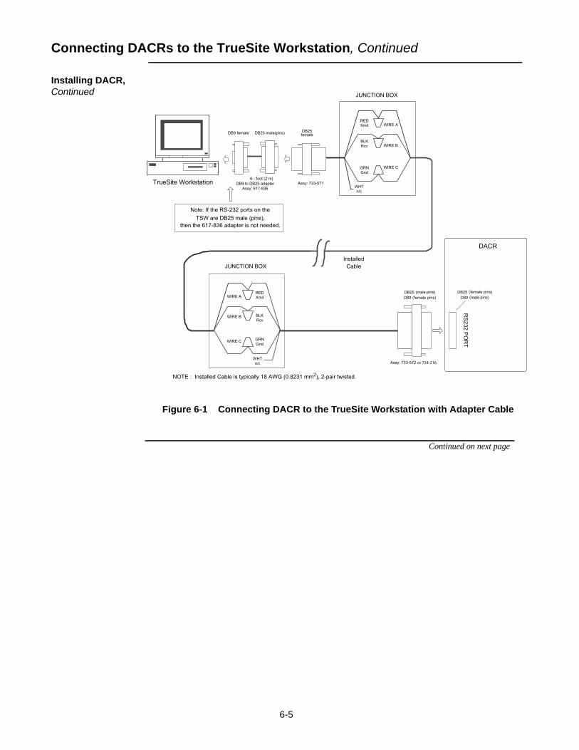
Notes: • If you are connecting the DACR to the TrueSite Workstation with an adapter cable (using DB9 connector), refer to the diagram in Figure 6-1 for detail.
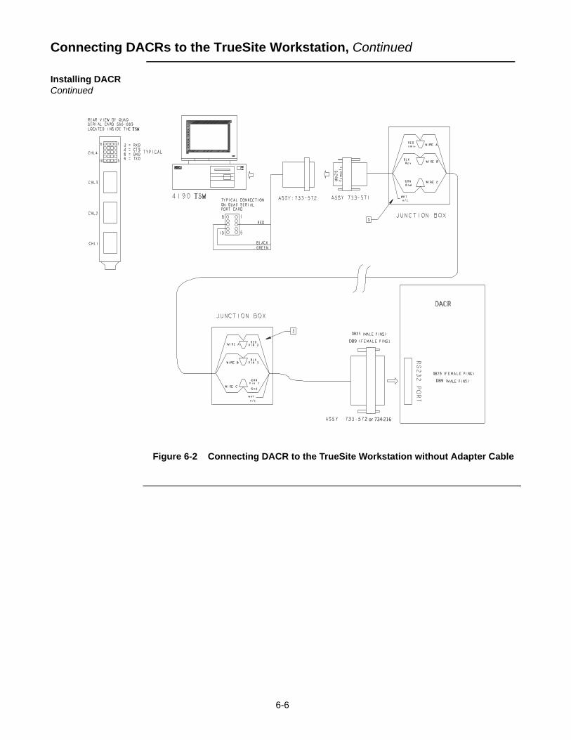
• If you are connecting the DACR to the TrueSite Workstation without an adapter cable (using DB25 connector), refer to the diagram in Figure 6-2 for detail.
2. Use the junction boxes at each end of the installed cable to terminate the field wiring between harness 733-571 and 733-572 (or 734-216 for AES).
Note: The total wiring length from the RS232 port of the CPU to the RS232 port of the DACR must not exceed 20 feet (610 cm) and must be run within conduit or equivalently protected against mechanical injury. Also, the TrueSite Workstation and DACR must be located in the same room. See page 6-5 for specifics on each receiver type
6-5
Connecting DACRs to the TrueSite Workstation, Continued
Installing DACR, Continued
Figure 6-1 Connecting DACR to the TrueSite Workstation with Adapter Cable
Continued on next page
6-6
Connecting DACRs to the TrueSite Workstation, Continued
Installing DACR Continued
Figure 6-2 Connecting DACR to the TrueSite Workstation without Adapter Cable

6-7
Connecting DACRs to the TrueSite Workstation, Continued
Configuring System III DACR Options
1. After connecting the DACR(s) to the TrueSite Workstation, turn the power ON.2. Press ENTER to bring up the login screen.3. Enter CAFÉ at the access code screen.4. Select the desired menu item:
• System Functions: To change Date and Time• Line Card Programming: To program the line card• CPM Options
- Set com settings- 07 – Baud rate: 9600- 08 – Data bits: 8- 09 – Parity: 0- Set heartbeat timer from 30 to 20- 12 – heartbeat timer: 20- Set number of line cards- 2E – number of line cards
Configuring Bosch D6600 DACR Options
1. After connecting the DACR(s) to the TrueSite Workstation, turn the power ON.2. Press M/E to log on.3. Enter 6600 and then M/E at the access code screen.4. Use the arrow keys to scroll and M/E to select the desired menu item:
• 2 CPU Configuration• Global
- Time Setup- Date Setup
• COM3 Automation Configuration- Baud Rate: 9600- Data Bit: 8- Parity: 0- Stop Bit: 1- Link Test: 30
Configuring AES Intellinet 7705i Receiver Options
1. The AES Intellinet 7705i Reciever is preset with the following COM configurations: - Baud Rate: 1200 - Data Bits: 7 - Parity: ODD - Stop Bits: 2
2. Refer to the AES Intellinet 7705i Reciever document number 40-7705I-IS for setup information for the receiver.
3. For UL Central Station Burglar Alarm Applications, opening/closing signals require an alternate communications means that provides for premises acknowledgement/ringback. Refer to the Intellinet Installation Instructions for details.


7-1
Chapter 7. Jumpers, Interrupts, and Switch Settings
Introduction Note: This chapter applies specifically to Simplex UL864 Listed PC stations.
This chapter provides information about installing boards (cards) in the TrueSite Workstation. TheTrueSite Workstation is usually shipped with the cards installed. However, if you do need to install acard or modify a configuration, you may find this information helpful. The jumper, switch and IRQsettings for the following cards are described in this appendix:
• Media cards for RS232 and wired configurations• UL I/O Card• Network Interface card(s)
In this Chapter This chapter discusses the topics listed in the following table. Refer to the page number listed after the topic for information on that topic.
Topic See Page #
Interrupt (IRQ) Settings 7-2
Jumper Settings 7-4
Switch Settings 7-5
Configuring the Devices 7-6
Interfacing with the Simplex Fire Network 7-7
Installing Cards and Jumpers 7-9
Installing the Second Video Card 7-11
Disabling the Reboot Watchdog 7-14

7-2
Interrupt (IRQ) Settings
Recommended Interrupt (IRQ) Settings
This section describes the interrupt settings for the TrueSite Workstation. Table 7-1 lists the recommended IRQ settings for the TrueSite Workstation.
Note: Make sure that COM1 and COM2 are enabled. Use the Ports icon in the Control Panel Group to make these changes.
TrueSite Workstation IRQ Settings
Table 7-1 show the recommended TrueSite Workstation IRQ settings.
Note: *If the Serial Touchscreen is used on PC COM1, use IRQ 4. (PC COM1 is now unavailable for other use.) If the Serial Touchscreen is used on PC COM2, use IRQ 3. (PC COM2 is now unavailable for other use.)
Note: **Port A and Port B are not available.
In the BIOS settings, IRQs 11 should be set to Reserved. The exact setting depends on the options available in the BIOS.
Table 7-1: Device IRQ Settings for Configurations Basic through 23
Configuration
Basic 1 2 3 4 5 6 7 8 9 10 11 12 13 14 15 16 17 18 19 20 21 22 23
PS/2 Mouse 12 12 12 12 12 12 12 12 12 12 12 12 12 12 12 12 12 12 12 12 12 12 12 12
Parallel Port 7 7 7 7 7 7 7 7 7 7 7 7 7 7 7 7 7 7 7 7 7 7 7 7
PC COM1 4 4 4 4 4 4 4 4 4 4 4 4 4 4 4 4 ** ** ** ** ** ** ** **
PC COM2 3 3 3 3 3 3 3 3 3 3 3 3 3 3 3 3 ** ** ** ** ** ** ** **
Serial Touchscreen* ** ** ** ** ** ** ** **
Tape Backup 15 15 15 15 15 15 15 15 15 15 15 15
UL I/O** 11 11 11 11 11 11 11 11 11 11 11 11

7-3
Interrupt (IRQ) Settings, Continued
Possible IRQ Settings
Table 7-2 lists the possible IRQ settings for the TrueSite Workstation.
Table 7-2: TrueSite Workstation Device - Reference IRQ Settings (see Table 7-1 for recommended settings)
TrueSite Workstation Device Possible IRQ Settings
2/9 3 4 5 7 10 11 12 15
Parallel Port X
PS/2 Mouse X
Tape Backup X
Serial Touchscreen X X
Network Card or Repeater (ISA)
X X X X
UL/IO X X X X X X
PC Serial COM1 X
PC Serial COM2 X

7-4
Jumper Settings
RS232 Media Card (P/N 565-327)
Table 7-3 lists the jumper configurations for all RS232 media cards.
Wired Media Card (P/N 565-413)
Table 7-4 lists the jumper configurations for all wired media cards.
Fiber Optic Media Assembly
There are no jumpers on the fiber optic media assembly.
Table 7-3: RS232 Media Card - Jumper Positions
Jumper Function Position
P3 Network Media Motherboard 1-2 (default)
Service Port 2-3
P4 Media Mother Board 1-2 (default)
Network and Service Port 2-3
P5 Supervised 1-2 (default)
Unsupervised 2-3
Table 7-4: Wired Media Card - Jumper Positions
Jumper Function Position
P2 18 AWG (0.8231 mm2) Cable 1&2
3&4
5&6
7&8
24 AWG (0.2047 mm2) Cable 3&4

7-5
Switch Settings
UL I/O Card (P/N 565-283)
This section explains how to configure the UL I/O Card (Model 4190-8403 TrueSite Workstationonly). Ensure that the switches are set on the UL I/O Card as listed in Table 7-5 and Table 7-6.
Table 7-5: UL I/O Card - Host Address I/O Selection Via SW1
Switch State
SWI1-1 OFF
SW1-2 OFF
SW1-3 OFF
SW1-4 OFF
Table 7-6: UL I/O Card - Configuration Via SW2
SwitchNo COM Ports (No Daughter
Cards - Default)
SW2-1 OFF
SW2-2 OFF
SW2-3 OFF
SW2-4 OFF
SW2-5 OFF
SW2-6 OFF
SW2-7 OFF
SW-8 OFF
7-6
Configuring the Devices
Configuring Device Drivers for Windows XP
To configure device drivers for Windows XP, complete the following steps: 1. Start the TrueSite Workstation Network Configurator.2. Load Job Configuration.3. Select the Registry Configuration from the Configure menu.
• When the Configuration dialog box appears, click the Apply button, exit the configurator, and reboot the computer.
Quad Serial Port Card
Up to 2 Quad Serial port cards can be installed. Refer to Figure 2-2 for location. The cards are Plug and Play.1. With the unit powered down insert the Quad Serial card and apply power.2. Plug and Play will display “New Hardware Found”. Select Next, Next, and Specify Location.3. Browse to “Downloads” “Quad Serial Win2K XP, Ser 15x”4. Select Open, OK, Finished.5. A new message, “Found New Hardware” will be displayed.6. Browse to “Downloads”: “Quad Serial Win2K XP, X8790 Port”.7. Select Open, OK, Finished. Ports 3-6 are now loaded.8. If a second card is needed. Repeat steps 1 and 2. The drivers will be automatically loaded. Ports
7-10 are now loaded.
Note: Port 10 cannot be used by TSW; if your application requires eight separate 2120 connections, then you will need to disable COM2 using the Windows Device Manager before adding two Quad Serial Port cards.

7-7
Interfacing with the Simplex Fire Network
Network Interface Card
This section explains how to install the 655-273 Network Interface Card (Wired) or the 655-272 Network Interface Card (Modular).
You can install up to four Network Interface Cards into one PC to support a multi-network configuration. Each Network Interface Card can support one network containing up to 98 nodes. TrueSite Workstation can support up to four networks consisting of up to 392 nodes. Ensure that the jumpers are set to the positions listed in Table 7-7 and Table 7-8 for each network card used.
*A Network Repeater card cannot serve as the network interface for point changes on the network.
Note: Address Range 200-207 must be selected for the UL I/O card.
Table 7-7: Network Interface Card - Jumper Positions
655-272 & 273 Network Card
Jumper Position Function
P1 1-2 57600 Baud
2-3 9600 Baud
P2 1-2 9 bit
2-3 8 bit
P6 1-2 Bypass Disabled
2-3 Bypass Enabled (default)
Table 7-8: Network Interface Card - Setting Card Address range in the Programmer
Address Range SW2-4 SW2-3 SW2-2 SW2-1 Device
200-207 Reserved for UL I/O Card
2B0-2B7 Network Card #1 (default)
2B8-2BF Network Card/Repeater* #2
2C0-2C7 Network Card/Repeater* #3
2C8-2CF Network Card/Repeater* #4
2D0-2D7 OFF ON OFF ON TBD
300-307 OFF ON ON OFF TBD
308-30F OFF ON ON ON TBD

7-8
Interfacing with the Simplex Fire Network, Continued
Network Interface Card Installation Sequence
To properly install the Network Interface card, follow one of the two sequences presented belowbased on the scenario.
PRIMARY SCENARIOIf the user does not have the ‘3.3/5V PCI Card Driver’ CD-ROM, follow this procedure:
1. Backup the system and notify all building personnel and occupants that the IMS is going offline until system upgrade is completed.
2. Shut down the Simplex UL864 Listed PC.3. Disable the power supply of the Simplex UL864 Listed PC by pushing switch situated at the back
of its tower.4. Strip off the case of the tower by doing the following:
a. Remove the screws in the back of the unit. Keep them in a bag or a container to avoid losing them.
b. Once the screws are removed, slide the case forward.5. Lift up the case to expose the components inside the PC tower.6. Insert the Network Card in the PCI slot and power the PC back up.7. Wait for “Found New Hardware” dialog message to appear.8. The dialog appears and displays: “Can Windows connect to Windows Update to search for
software?” In the prompt, select “No, not this time”.9. Select “Install from a list or specific location (Advanced)”.10. Select the “Don’t search” radio button, then click Next.11. There are two possibilities:
a. If the message “Simplex PCI Network Interface Card 3.3V” does not show up in the list of compatible hardware, proceed to Step 9.
a. Otherwise if the message appears, click Next.12. Click Have Disk.13. Browse to C:\Windows\system32\drivers\simplex.inf, click Open, and then click Next.14. Click Yes for the “Update Driver Warning”.15. You will receive the following message: “has not passed Windows Logo testing”. Choose
Continue Anyway.16. Once the installation is complete, click Finish and restart the PC.
SECONDARY SCENARIOIf the user has the ‘3.3/5V PCI Card Driver’ CD-ROM, follow this procedure:
1. See Steps 1 through 5 above.2. Insert the Network Card in the PCI slot and power the PC back up.3. Place the ‘3.3/5V PCI Card Driver CD-ROM’ in the CD-ROM drive.4. Wait for “Found New Hardware” dialog message to appear.5. The dialog appears and displays: “Can Windows connect to Windows Update to search for
software?” In the prompt, select “No, not this time”.6. Select “Install Software Automatically (Recommended)”.7. After the wizard finds the PCI Network Interface Card, you will receive the following message:
“has not passed Windows Logo testing”. Choose Continue Anyway.8. Once the installation is complete, click Finish and restart the PC.
7-9
Installing Cards and Jumpers
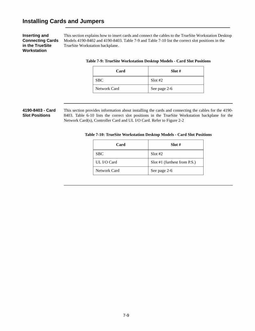
Inserting and Connecting Cards in the TrueSite Workstation
This section explains how to insert cards and connect the cables to the TrueSite Workstation Desktop Models 4190-8402 and 4190-8403. Table 7-9 and Table 7-10 list the correct slot positions in the TrueSite Workstation backplane.
4190-8403 - Card Slot Positions
This section provides information about installing the cards and connecting the cables for the 4190-8403. Table 6-10 lists the correct slot positions in the TrueSite Workstation backplane for theNetwork Card(s), Controller Card and UL I/O Card. Refer to Figure 2-2
Table 7-9: TrueSite Workstation Desktop Models - Card Slot Positions
Card Slot #
SBC Slot #2
Network Card See page 2-6
Table 7-10: TrueSite Workstation Desktop Models - Card Slot Positions
Card Slot #
SBC Slot #2
UL I/O Card Slot #1 (furthest from P.S.)
Network Card See page 2-6

7-10
Installing Cards and Jumpers, Continued
Continuity Check for Model 4190-8403 with UL I/O Card Installed
For 4190-8403 TrueSite Workstation systems with the terminal block mounted to the PC chassis, verify the information listed in Table 7-11.
Verifying Tape Drive Installation
Verify that the tape drive has been installed, as follows:1. Verify that no jumper exists on the tape drive jumpers DSP, DS0, or DS1.2. Install the Tape Drive into the TrueSite Workstation as defined in the IOMEGA instruction
manual.3. Disconnect the connector from the TrueSite Workstation floppy and connect it to the connector
on the tape drive.
Reboot Watchdog If a UL I/O Card (P/N 565-283) is installed and you want to exit the TrueSite Workstation application because you plan to run other applications, run the Watchdog32 application from the Start menu to disable the reboot watchdog on the UL I/O Card. Disabling the reboot watchdog prevents the PC from rebooting.
Table 7-11: TrueSite Workstation 4190-8403 Model with UL I/O Card - Device Connection Points for Outputs 1 & 2
Location Value Function
TB1-2 to TB1-4 Short (<1 ohm) Output #1 Relay Normally Closed
TB1-8 to TB1-10 Short (<1 ohm) Output #2 Relay Normally Closed
TB1-4 to TB1-6 Open Circuit Output #1 Relay Normally Closed
TB1-10 to TB1-12 Open Circuit Output #2 Relay Normally Closed

7-11
Installing the Second Video Card
Installation Procedure
In order for the TrueSite Workstation to support the dual monitor, a second video card must be installed.
Complete the following steps to install the second video card to support the dual monitor option:
1. Start the PC.2. Hold down the Delete key to interrupt the boot process. This bypasses the boot sequence and
redirects you to the BIOS.3. Disable the on-board VGA:For the 4190-7007 or 4190-7008 PC:
a. In BIOS, select “Advanced Chipset Features”.b. Set “Init Display First” to [PCI Slot].c. Set “On-Chip VGA” to [Disabled].d. Save and exit BIOS.
For the 4190-7005 or 4190-7006 PC:a. In BIOS, select “Integrated Peripherals”.b. In “Integrated Peripherals”, make sure “Init Display First” is set to [PCI].c. Save and exit BIOS.d. Shut down the PC.e. With the unit powered off, disable the on-board VGA by placing a jumper on J3 of the
Single Board Computer (SBC) (see Figure 7-1). Insert the NVIDIA Video-338PCI-DVI (video card in PCI slot 3-3).
Figure 7-1 Jumper Location of SBC
4. Attach the monitor to the top video connector on the NVIDIA Video board. If both monitors are RGB, Attach the DVI to RGB connector to the middle connector, see Figure 7-2.

7-12
Installing the Second Video Card, Continued
Figure 7-2 Monitor Connections
Note: This is not necessary if the 2nd monitor is DVI.
5. Start the PC and log in, then exit TrueSite Workstation if it is set up to start automatically. (If TrueSite Workstation does not start, a message is displayed to indicate that the TSW requires 1024 x 768 resolution minimum.)
6. Microsoft Windows XP may detect this new video card and places the appropriate display drivers from its system folder automatically. To maximize the video board acceleration and increase the performance, insert the “Video Master Installer” CD that came with the board into the CD drive.
7. CD Autorun feature brings up the “Welcome Screen”. Using your mouse, select “Display Driver”. (If Autorun fails, please review Readme.txt file on the CD).
8. At this point the installation copies all driver files. Once the installation completes, the system prompts you to “restart” the PC. Remove the CD and accept this.
9. When the system restarts, log in, then exit TrueSite Workstation if it is set up to start automatically. (If TrueSite Workstation does not start, a message is displayed to indicate that the TSW requires 1024 x 768 resolution minimum.)
10. Right-click on the desktop and select “properties”.11. Click the “Settings” tab, set the resolution to 1024 by 768 pixels and color quality to highest (32
bit). Click apply and select Yes to accept.12. Click the “Screen Saver” tab. Select “None”, click Apply. 13. Select “Power”. In settings for Home/Office Desk power scheme, turn off monitor select Never,
then Apply, then OK.14. Close this window, click Start and shutdown the PC. Power off when done.15. Plug in the second monitor to the adapter plug on the NVIDIA Video card.
Continued on next page

7-13
Installing the Second Video Card, Continued
Installation Procedure, Continued
16. Start the PC and log in, then exit TrueSite Workstation if it was setup to start automatically.17. If the NVDIA Display setup wizard appears click cancel.18. Right-click on the desktop and select “properties”.19. Click the “Settings” tab, both monitors will be displayed. Select number 2. Set the resolution to
1024 by 768 pixels and color quality to highest (32 bit). Click apply and select Yes to accept.20. Click the “Extend my Windows desktop onto this monitor” checkbox to enable. Click Apply,
then OK. You can now move windows from one monitor to another.For Clone mode21. Double-click the second monitor Icon (2) to invoke the Monitor Properties dialog.22. Click on the “GeForce 6200” tab.23. Change the nView Display mode from “Dualview” to “Clone”.24. Click OK to accept changes. Then OK to close the window.

7-14
Disabling the Reboot Watchdog
Reboot Watchdog If a UL Card (565-283) is installed and you want to exit the TrueSite Workstation Run-time becauseyou plan to run other applications, run the Watchdog32 application fromC:\Simplex\TrueSite\TSW\config\Watchdog32.exe to disable the reboot on the UL card. Disabling thereboot watchdog prevents the PC from rebooting.

8-1
Chapter 8. Simplex 4190 TrueSite Workstation Checkout
Introduction This chapter describes how to checkout the Simplex 4190 TrueSite Workstation system, to show youhow the system will work when it is programmed and operating
In this Chapter This chapter discusses the topics listed in the following table. Refer to the page number listed after thetopic for information on that topic.
Topic See Page #
How to Checkout the TrueSite Workstation 8-2
Testing Circuit Supervision 8-2

8-2
Simplex 4190 TrueSite Workstation Checkout
How to Checkout the TrueSite Workstation
You can use the simulation function provided to check out the system. The simulation function showsyou how the system will work when it is finally programmed and operating.
Testing Circuit Supervision
Use the following procedures in the table below to confirm that the network is supervising for opens,shorts and grounds. The right column in this table shows what is displayed on the TrueSiteWorkstation monitor screen when an open, short, or ground occurs on a circuit.
Table 8-1: TrueSite Workstation Display Conditions
Condition TrueSite Workstation Monitor Screen
Open -- Open a line on a supervised circuit to make cir-cuit impedance infinite.
Trouble Statement
Short -- Apply a zero ohm jumper across the circuit.
Trouble Statement
Earth Ground -- Place a 10k or smaller value resistor from supervised wiring to Earth Ground.
If an Earth Ground occurs on any circuit, the Earth Fault Trouble Statement occurs.


© 2007 Tyco Safety Products Westminster, Westminster, MA 01441-001 USA. Specifications and other information were current as of publication and are subject to change without notice.
579-834Rev. C