simple introduction into energy management with wincc · simple introduction into energy management...
TRANSCRIPT

Applications & Tools
Answers for industry.
Cover
Simple Introduction into Energy Management with WinCC
WinCC
Application Description December 2011

2 Energy management with WinCC
V1.1, Entry ID: 48586219
Co
pyr
igh
t
Sie
me
ns
AG
20
11
All
righ
ts r
ese
rve
d
Industry Automation and Drive Technologies Service & Support Portal
This article is taken from the Service Portal of Siemens AG, Industry Automation and Drive Technologies. The following link takes you directly to the download page of this document.
http://support.automation.siemens.com/WW/view/en/48586219
Caution The functions and solutions described in this article confine themselves to the realization of the automation task predominantly. Please take into account furthermore that corresponding protective measures have to be taken up in the context of Industrial Security when connecting your equipment to other parts of the plant, the enterprise network or the Internet. Further information can be found under the Content-ID 50203404.
http://support.automation.siemens.com/WW/view/en/50203404
If you have any questions about this document, please contact us at the following e-mail address:

Energy management with WinCC V1.1, Entry ID: 48586219 3
Co
pyr
igh
t
Sie
me
ns
AG
20
11
All
righ
ts r
ese
rve
d
s
SIMATIC Energy Management with WinCC
Simple Introduction into Energy Management with WinCC
Fehler! Verweisquelle konnte nicht gefunden werden.
1
Automation Solution
2
Installation
3 Starting up the Application (own project)
4
Starting up the Application (Sample Project)
5
Operating the Application
6 Expanding the Application Example with SIMATIC Powerrate
7
Literature
8
History
9

Warranty and Liability
4 Energy management with WinCC
V1.1, Entry ID: 48586219
Co
pyr
igh
t
Sie
me
ns
AG
20
11
All
righ
ts r
ese
rve
d
Warranty and Liability Note The application examples are not binding and do not claim to be complete
regarding configuration, equipment and any eventuality. The application examples do not represent customer-specific solutions. They are only intended to provide support for typical applications. You are responsible for ensuring that the described products are used correctly. These application examples do not relieve you of your responsibility to use sound practices in application, installation, operation and maintenance. When using these application examples, you recognize that we cannot be made liable for any damage/claims beyond the liability clause described. We reserve the right to make changes to these application examples at any time and without prior notice. If there are any deviations between the recommendations provided in this application example and other Siemens publications – e.g. catalogs – the contents of the other documents have priority.
We accept no liability for information contained in this document.
Any claims against us – based on whatever legal reason – resulting from the use of the examples, information, programs, engineering and performance data etc., described in this Application Example shall be excluded. Such an exclusion shall not apply in the case of mandatory liability, e.g. under the German Product Liability Act (“Produkthaftungsgesetz”), in case of intent, gross negligence, or injury of life, body or health, guarantee for the quality of a product, fraudulent concealment of a deficiency or breach of a condition which goes to the root of the contract (“wesentliche Vertragspflichten”). However, claims arising from a breach of a condition which goes to the root of the contract shall be limited to the foreseeable damage which is intrinsic to the contract, unless caused by intent or gross negligence or based on mandatory liability for injury of life, body or health. The above provisions do not imply a change in the burden of proof to your disadvantage.
It is not permissible to transfer or copy these application examples or excerpts thereof without express authorization from Siemens Industry Sector.

Preface
Energy management with WinCC V1.1, Entry ID: 48586219 5
Co
pyr
igh
t
Sie
me
ns
AG
20
11
All
righ
ts r
ese
rve
d
48
586
219
_Ene
rgym
ana
ge
men
t_e
n.d
oc
Preface
Simple energy management
The first and basic step in energy management is to be aware of the energy consumption.
This is the approach of this application example. Using standard WinCC tools you are provided with an overview of your energy consumption, and on this basis, you will be able to derive further steps for increasing the energy efficiency of your plant.
Additionally, this example with WinCC faceplates shall serve as a template for the realization in your plant.

Table of Contents
6 Energy management with WinCC
V1.1, Entry ID: 48586219
Co
pyr
igh
t
Sie
me
ns
AG
20
11
All
righ
ts r
ese
rve
d
Table of Contents Warranty and Liability ................................................................................................. 4 Preface .......................................................................................................................... 5 Table of Contents......................................................................................................... 6 1 Automation Task................................................................................................ 7
1.1 Introduction........................................................................................... 7 1.2 Overview of the automation task.......................................................... 7 1.3 Description of the automation task....................................................... 7
2 Automation Solution ......................................................................................... 8 2.1 Overview of the general solution.......................................................... 8 2.2 Description of the core functionality ..................................................... 9 2.3 Hardware and software components used......................................... 10 2.4 Possible expansions of the application example ............................... 11
3 Installation........................................................................................................ 12 3.1 Hardware installation.......................................................................... 12 3.2 Installation and preparation of the operator station............................ 13
4 Starting up the Application (own project) ..................................................... 14 4.1 Preparation......................................................................................... 14 4.2 Commissioning................................................................................... 14
5 Starting up the Application (Sample Project) ............................................... 19 5.1 Preparation......................................................................................... 19 5.2 Commissioning................................................................................... 19
6 Operating the Application............................................................................... 20 6.1 Overview ............................................................................................ 20 6.2 Operating the faceplate...................................................................... 23
7 Expanding the Application Example with SIMATIC Powerrate................... 31 7.1 Connecting the SENTRON PAC via free of charge Modbus TCP block31 7.2 Connecting the SENTRON PAC via licensed TCP block by Siemens I
IS ........................................................................................................ 31 7.3 Connecting the SENTRON PAC via an additional Profinet module .. 31
8 Literature .......................................................................................................... 32 9 History............................................................................................................... 32

1 Automation Task
1.1 Introduction
Energy management with WinCC V1.1, Entry ID: 48586219 7
Co
pyr
igh
t
Sie
me
ns
AG
20
11
All
righ
ts r
ese
rve
d
1 Automation Task
1.1 Introduction
The objective of this application example is to provide a simple introduction into energy management using “WinCC standard tools”.
1.2 Overview of the automation task
The figure below provides an overview of the automation task.
Figure 1-1
1.3 Description of the automation task
The parameters necessary for the energy management for one or several consumers shall be displayed in WinCC. In this application example several Sentron PAC are connected to WinCC via a Modbus TCP connection and the values are displayed in the WinCC faceplate.

2 Automation Solution
2.1 Overview of the general solution
8 Energy management with WinCC
V1.1, Entry ID: 48586219
Co
pyr
igh
t
Sie
me
ns
AG
Co
pyr
igh
t 20
11 A
ll rig
hts
re
serv
ed
2 Automation Solution
2.1 Overview of the general solution
Schematic layout
The following figure gives a schematic overview of the most important components of the solution:
Figure 2-1
Head-end station
The head-end station consists of one WinCC PC which is coupled via Ethernet cable and a Modbus TCP connection. The network branches to the SENTRON PAC stations via an Ethernet switch (e.g. SCALANCE X208).
Sentron PAC
SENTRON PAC is a multi-function measuring device for display, saving and monitoring all relevant network parameters in the low-voltage energy distribution. A detailed description of SENTRON PAC 3200 or 4200 is available in the manual.
SENTRON PAC 3200: http://support.automation.siemens.com/WW/view/26504150
SENTRON PAC 4200: https://www.automation.siemens.com/mdm/default.aspx?DocVersionId=25599329163&TopicId=

2 Automation Solution
2.2 Description of the core functionality
Energy management with WinCC V1.1, Entry ID: 48586219 9
Co
pyr
igh
t
Sie
me
ns
AG
20
11
All
righ
ts r
ese
rve
d
2.2 Description of the core functionality
Overview and description of the user interface
Figure 2-2
2-wire copper cable (twisted pair cable) 2-wire copper cable (twisted pair cable)
Energy Appliance ApplianceEnergy
SENTRON PAC SENTRON PAC
SIMATIC WinCC
SCALANCE X208
WinCC FaceplateWinCC Faceplate
Core functionality
The application example provides WinCC faceplates with icon for the SENTRON PAC measuring devices for displaying basic measured values and visualizing them as trend curves.
The individual labels and units can be adjusted individually.
Advantages of this solution
The solution presented here offers you the following advantages:
Energy management of users without additional costs using WinCC standard tools
Option to expand the functions with SIMATIC powerrate
Monitoring the consumption values with this application enables choosing more cost-efficient contracts
Very simple and quick integration of SENTRON PACs into your own WinCC projects.
Simple adjustment to individual requirements due to plenty of options for faceplate settings.

2 Automation Solution
2.3 Hardware and software components used
10 Energy management with WinCC
V1.1, Entry ID: 48586219
Co
pyr
igh
t
Sie
me
ns
AG
Co
pyr
igh
t 20
11 A
ll rig
hts
re
serv
ed
2.3 Hardware and software components used
The application document was generated using the following components:
Hardware components
Table 2-1
Component Qty. MLFB / order number Note
Industrial PC 1 Industrial PC
http://www.automation.siemens.com/mcms/automation/en/pc-based-automation/Pages/Default.aspx
SCALANCE X208 1 6GK5208-0BA10-2AA3
SENTRON PAC 3200 1 7KM2112-0BA00-3AA0
SENTRON PAC 4200 1 7KM4212-0BA00-3AA0
Standard software components
Table 2-2
Component Qty. MLFB / order number Note
WinCC V7.0 SP2 1 6AV6 381-2BM07-0AX0 (128 power tags)
Version depends on the subsequent configuration. 128 tags are sufficient for the demo project.
Sample files and projects
The following list includes all files and projects used in this example.
Table 2-3
File Note
Energy.zip This zipped file contains the WinCC project as well as the Excel file for the tag import.
Einstieg_Einfaches_Energiemanagement_mit_WinCC_de.pdf
This document.

2 Automation Solution
2.4 Possible expansions of the application example
Energy management with WinCC V1.1, Entry ID: 48586219 11
Co
pyr
igh
t
Sie
me
ns
AG
20
11
All
righ
ts r
ese
rve
d
2.4 Possible expansions of the application example
SIMATIC powerrate
This application example, can amongst others, be expanded with SIMATIC powerrate. SIMATIC powerrate continuously records, archives and processes the energy data further. Exact knowledge of the consumer profile enables the tracing of saving potentials, makes energy procurement more efficient, and hence reduces the energy costs. Monitoring the contractually agreed power limit also helps avoiding unnecessarily high prices per kilowatt or penalties, and on the other hand actually makes full use of the defined power limit. A detailed function description with entry ID "48355131" is available in the Online Support.
WinCC/B.Data
This application example can be further expanded with the WinCC/B.Data option. WinCC/B.Data provides the basis for economic energy plant management to reduce the energy costs and increase the energy efficiency. The direct advantages for you are listed individually below:
Creates cross-company transparency through consistent energy and material accounting for the power generation and consumption plants
Enables originator-based energy cost allocation and creates a transition to the accounting system (e.g. SAP R/3 CO)
Forms characteristic values which enable founded statements on the increase of the efficiency of power generation plants and consumers
Provides planning reliability through production-related load and demand prognosis
Supports the purchasing department in cost-optimized energy procurement
Fulfills the legal requirements for monitoring and reporting of greenhouse gas emissions (CO2 emissions)
Load relief due to the automatic operation of internal and external energy reporting system.
A detailed function description is available in the Online Support under entry ID: 47521082).

3 Installation
3.1 Hardware installation
12 Energy management with WinCC
V1.1, Entry ID: 48586219
Co
pyr
igh
t
Sie
me
ns
AG
Co
pyr
igh
t 20
11 A
ll rig
hts
re
serv
ed
3 Installation
3.1 Hardware installation
The figure below shows the hardware setup of the application.
Figure 3-1

3 Installation
3.2 Installation and preparation of the operator station
Energy management with WinCC V1.1, Entry ID: 48586219 13
Co
pyr
igh
t
Sie
me
ns
AG
20
11
All
righ
ts r
ese
rve
d
3.2 Installation and preparation of the operator station
Table 3-1
No. Action Comment
1 Start or install a computer with WinCC V7.0 SP1.
2 Open the WinCC Explorer and select “Tag Management” with the right mouse button, and select the “Add New Driver…” from the context menu.
3 In the window below you select the “Modbus TCPIP.chn” file and press the “Open” button to add the Modbus TCP channel driver.
4 Repeat step 3 with the “System Info.chn” file to add the system info channel driver.

4 Starting up the Application (own project)
4.1 Preparation
14 Energy management with WinCC
V1.1, Entry ID: 48586219
Co
pyr
igh
t
Sie
me
ns
AG
Co
pyr
igh
t 20
11 A
ll rig
hts
re
serv
ed
4 Starting up the Application (own project) The faceplate described in this application requires you to also define the supplied start screen “@BST_MAIN_1M.pdl” (when using a monitor) or “@BST_MAIN_2M.pdl” (when using two monitors) as the start screen in your WinCC project.
4.1 Preparation
Table 4-1
No. Action Comment
1 Copy the “Energy_Files.zip” file to your hard drive and unzip it into a directory.
2 Copy the files from the folders “Block” and “Pictures” into the “GraCS” folder of your WinCC project (\project path\GraCS).
3 Copy the files from the “Library” folder into the “Library” folder of your WinCC project (\project path\Library).
4 Copy the files from the “CSV files” folder into the master directory of your WinCC project path. (These files are required to create the tags and structures.)
4.2 Commissioning
Table 4-2
No. Action Comment
1 Start the WinCC Explorer and create “@BST_MAIN_1M.pdl” or “@BST_MAIN_2M.pdl” as start screen, depending on the number of your monitors or call one of these two screens from your existing picture navigation. If you have created a new WinCC project, configure the additional properties of your WinCC project (e.g. Global Script Runtime, Graphics Runtime, etc.).
2 In the context menu of the Modbus unit you select the “New Driver Connection…” option to add a new Modbus connection.

4 Starting up the Application (own project)
4.2 Commissioning
Energy management with WinCC V1.1, Entry ID: 48586219 15
Co
pyr
igh
t
Sie
me
ns
AG
20
11
All
righ
ts r
ese
rve
d
No. Action Comment
3 In the subsequent window you assign a name for the created connection and select the “Properties” interface to open the settings dialog.
4 Change the “Modbus TCPIP properties” as can be seen in the screen shot. CPU type: “Premium Micro” Server: “IP address of the Sentron PAC” Port : “502” Address of remote slave: “1“ Acknowledge the entries in both windows by pressing “OK”. Note: A detailed description of this procedure can be found in entry 37885119.
5 Open the WinCC Tool “TAG Export Import” via the Windows start menu “SIMATIC>WINCC>Tools>TAG Export Import” to create the tags and structures.
6 Check whether the correct project path or project name is displayed in the first line in the “TAG Export Import” tool. Now select the “Import overwrite” option and click the “Get from Regional Settings” button to select the correct “List separator”. Now click the “Execute” button to execute the process, in order to import the tags and structures into your project. Confirm the security query for overwriting with the “OK” button. Note: when using a different project name, the “Filename” must be changed to “Energy” in this window, since the project name will be entered here by default. This import creates the “Sentron_PAC” structure tag as well as the “Internal Tags” in the “Properties” folder. These “Internal tags” are necessary for the configuration in the “Property screen” (also see chapter 6.1).

4 Starting up the Application (own project)
4.2 Commissioning
16 Energy management with WinCC
V1.1, Entry ID: 48586219
Co
pyr
igh
t
Sie
me
ns
AG
Co
pyr
igh
t 20
11 A
ll rig
hts
re
serv
ed
No. Action Comment
7 Now you create the tags for the access of WinCC to SENTRON PAC. To create these tags you need to select the connection created in step 2 and 3 (“PAC4200_1” in the example) and select the “New Tag…” entry in the context menu.
8 In the “Tag properties” window you assign a name (TagPrefix) for the tag to be created (“PAC4200_1” in the example) and select the “Sentron_PAC” structure as “DataType”.
9 In the “Invalid Address Parameter” you press the “No” button, since the addresses for the individual tags are assigned in a later step. Now all required tags for the access are created and automatically supplied with the “TagPrefix”.
10 Open the WinCC Tool “TAG Export Import” again to define the “Offsets” for the structure created in step 8 and 9. Export your respective tags using the “AG Export Import” WinCC Tool. Select the “Export” option and start the export by pressing the “Execute” button. Also check whether the correct project has been selected in the tool.
4 Starting up the Application (own project)
4.2 Commissioning
Energy management with WinCC V1.1, Entry ID: 48586219 17
Co
pyr
igh
t
Sie
me
ns
AG
20
11
All
righ
ts r
ese
rve
d
No. Action Comment
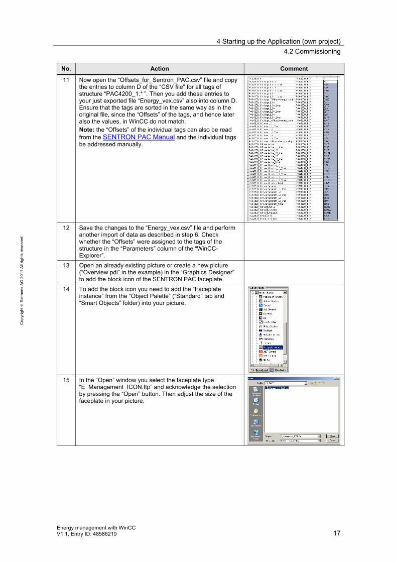
11 Now open the “Offsets_for_Sentron_PAC.csv” file and copy the entries to column D of the “CSV file” for all tags of structure “PAC4200_1.* ”. Then you add these entries to your just exported file “Energy_vex.csv” also into column D. Ensure that the tags are sorted in the same way as in the original file, since the “Offsets” of the tags, and hence later also the values, in WinCC do not match. Note: the “Offsets” of the individual tags can also be read from the SENTRON PAC Manual and the individual tags be addressed manually.
12 Save the changes to the “Energy_vex.csv” file and perform another import of data as described in step 6. Check whether the “Offsets” were assigned to the tags of the structure in the “Parameters” column of the “WinCC-Explorer”.
13 Open an already existing picture or create a new picture (“Overview.pdl” in the example) in the “Graphics Designer” to add the block icon of the SENTRON PAC faceplate.
14 To add the block icon you need to add the “Faceplate instance” from the “Object Palette” (“Standard” tab and “Smart Objects” folder) into your picture.
15 In the “Open” window you select the faceplate type “E_Management_ICON.ftp” and acknowledge the selection by pressing the “Open” button. Then adjust the size of the faceplate in your picture.

4 Starting up the Application (own project)
4.2 Commissioning
18 Energy management with WinCC
V1.1, Entry ID: 48586219
Co
pyr
igh
t
Sie
me
ns
AG
Co
pyr
igh
t 20
11 A
ll rig
hts
re
serv
ed
16 Add a “C-Action…” with the following script to the “Mouse
Action” event: #include "BST_FPDEF.h" char *pch; char szTagName[128]; char *szTagPrefix; char szLinkName[128]; int pointer; LINKINFO linkinfo; BST_TopfieldOpen(lpszPictureName, lpszObjectName, BST_FP_Engery);
17 Go to the “Properties” tab and select the “UserDefined2” tree entry of the “Object Properties” of the block icon, to connect the tags to be displayed in the icon during runtime. Furthermore, you can connect the tags for the “units” to have them displayed accordingly.
18 In the “Faceplate_Name” attribute you enter a name to be displayed in the text box during runtime. Note: for a better allocation of picture window to block icon it is recommended to assign the TagPrefix to the structure (“PAC4200_1” in the example) in this attribute, since the TagPrefix is also automatically displayed in the picture window.
19 Open the “@BST_BOTTOM.pdl” picture and adjust the picture call of the first button for the “Overview.pdl” picture (when using your own picture to integrate the block icon, enter this picture name). The picture call is realized through a “C Action” on the “Mouse Action” event. The second button already contains the picture call for the “E_Property.Pdl” picture. The other buttons can be deleted or used for the picture navigation of additional pictures.

5 Starting up the Application (Sample Project)
5.1 Preparation
Energy management with WinCC V1.1, Entry ID: 48586219 19
Co
pyr
igh
t
Sie
me
ns
AG
20
11
All
righ
ts r
ese
rve
d
5 Starting up the Application (Sample Project)
5.1 Preparation
Table 5-1
No. Action Comment
1 Start the computer prepared in chapter 3.
2 Unzip the “Energy.zip” file (WinCC project) onto the hard drive of your computer.
5.2 Commissioning
Table 5-2
No. Action Comment
1 Open the WinCC project and adjust the computer name according to your computer name in the sample project. For this purpose, click “Computer properties” with the right mouse button to open the dialog and enter the “Computer Name” of your computer in the input field.
2 Adjust the IP addresses of both SENTRON PAC stations in the Modbus connections. Open the properties of the respective Modbus connection as illustrated in the screenshot.
3 Start WinCC Runtime.

6 Operating the Application
6.1 Overview
20 Energy management with WinCC
V1.1, Entry ID: 48586219
Co
pyr
igh
t
Sie
me
ns
AG
Co
pyr
igh
t 20
11 A
ll rig
hts
re
serv
ed
6 Operating the Application
6.1 Overview
“Start screen”
The figure below displays the “start screen” of the sample project with two integrated faceplate instances as well as the respective picture window. The bottom part contains the buttons which enable you to switch from the “Start
screen” to the “Property screen” , the “Alarm screen” as well as the
“SysInfo screen” .
Figure 6-1
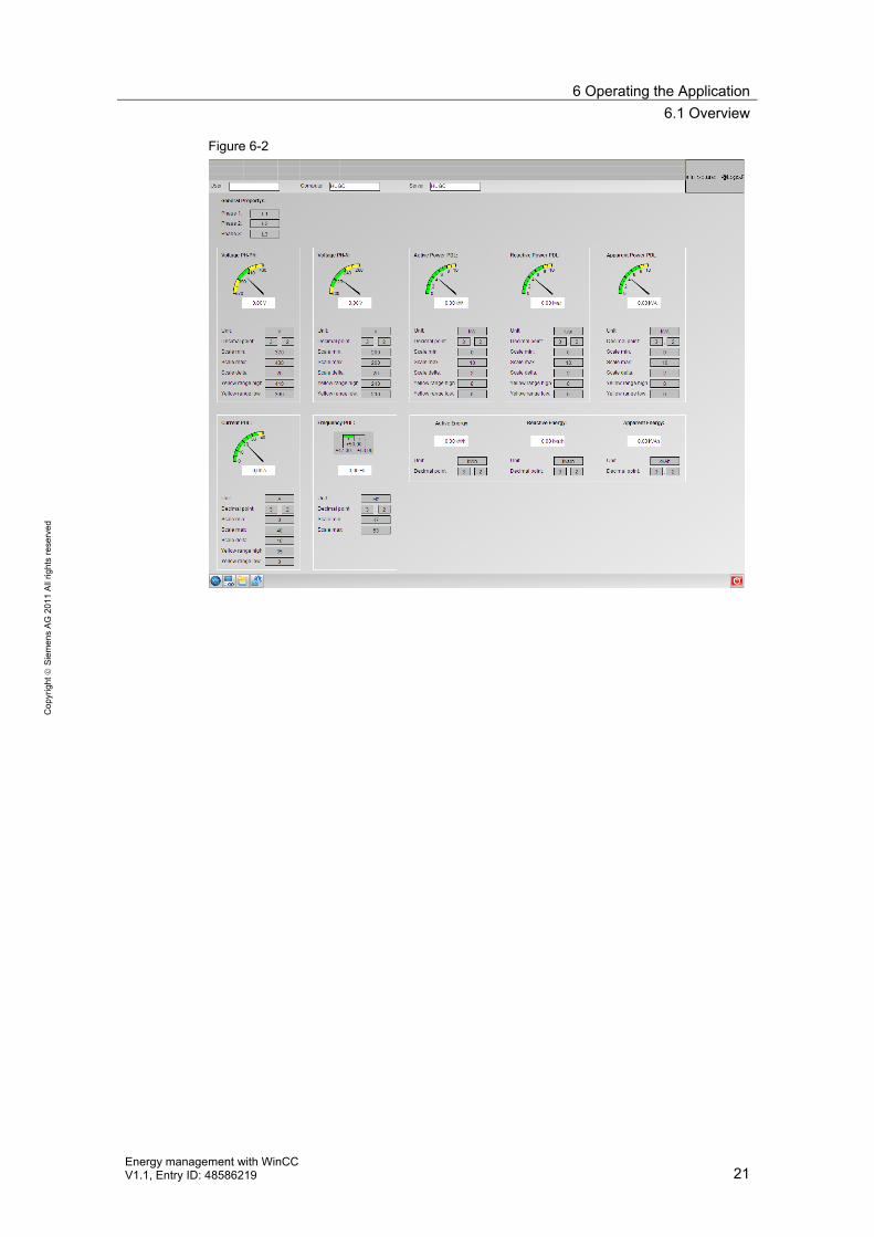
“Property screen”
In this screen you can change and set the properties for the various views of the faceplate (e.g. places before or after the decimal point, scale range, labeling text for the individual phases, etc.) for the entire project.
6 Operating the Application
6.1 Overview
Energy management with WinCC V1.1, Entry ID: 48586219 21
Co
pyr
igh
t
Sie
me
ns
AG
20
11
All
righ
ts r
ese
rve
d
Figure 6-2

6 Operating the Application
6.1 Overview
22 Energy management with WinCC
V1.1, Entry ID: 48586219
Co
pyr
igh
t
Sie
me
ns
AG
Co
pyr
igh
t 20
11 A
ll rig
hts
re
serv
ed
“SysInfo screen”
This screen shows some example data of your PC.
Note This screen is only available in the sample project, if you would like to integrate it into your own project, you have to extract it from the “zip file” of the sample project and manually create the necessary tags for the system info channel.
Figure 6-3

6 Operating the Application
6.2 Operating the faceplate
Energy management with WinCC V1.1, Entry ID: 48586219 23
Co
pyr
igh
t
Sie
me
ns
AG
20
11
All
righ
ts r
ese
rve
d
6.2 Operating the faceplate
After you have integrated the faceplate as described in chapter 4, or you are using the sample project, you can operate the faceplate as described below.
Clicking on the faceplate instance opens a picture window where you can change between the various views by pressing the respective buttons. These views are described further in the following sections. There is the additional option to open a screen with 6 predefined WinCC pictures via the “Loop display” button. In the first line of the faceplate the tag prefix used for this faceplate is displayed. It was also configured in the faceplate instance to be able to generate an assignment between picture window and faceplate instance.
“Voltage PH-PH” view
Pressing the button opens the “Voltage PH-PH” view in the picture window of the faceplate. This view depicts the voltages between the three phases using the respective current values (black needle) as well as the maximum value (red needle).
Figure 6-4
“Voltage PH-N” view
Pressing the button opens the “Voltage PH-N” view in the picture window of the faceplate. This view depicts the voltages between the three phases using the respective current values (black needle) as well as the maximum value (red needle).

6 Operating the Application
6.2 Operating the faceplate
24 Energy management with WinCC
V1.1, Entry ID: 48586219
Co
pyr
igh
t
Sie
me
ns
AG
Co
pyr
igh
t 20
11 A
ll rig
hts
re
serv
ed
Figure 6-5
“Current” view
Pressing the button opens the “Current” view in the picture window of the faceplate. This view depicts the currents between the three phases using the respective current values (black needle) as well as the maximum value (red needle).
Figure 6-6

6 Operating the Application
6.2 Operating the faceplate
Energy management with WinCC V1.1, Entry ID: 48586219 25
Co
pyr
igh
t
Sie
me
ns
AG
20
11
All
righ
ts r
ese
rve
d
“Active Power” view
Pressing the button opens the “Active Power” view in the picture window of the faceplate. This view depicts the active power between the three phases using the respective current values (black needle) as well as the maximum value (red needle).
Figure 6-7
“Reactive Power” view
Pressing the button opens the “Reactive Power” view in the picture window of the faceplate. This view depicts the reactive power between the three phases using the respective current values (black needle) as well as the maximum value (red needle).

6 Operating the Application
6.2 Operating the faceplate
26 Energy management with WinCC
V1.1, Entry ID: 48586219
Co
pyr
igh
t
Sie
me
ns
AG
Co
pyr
igh
t 20
11 A
ll rig
hts
re
serv
ed
Figure 6-8
“Apparent Power” view
Pressing the button opens the “Apparent Power” view in the picture window of the faceplate. This view depicts the apparent power between the three phases using the respective current values (black needle) as well as the maximum value (red needle).
Figure 6-9

6 Operating the Application
6.2 Operating the faceplate
Energy management with WinCC V1.1, Entry ID: 48586219 27
Co
pyr
igh
t
Sie
me
ns
AG
20
11
All
righ
ts r
ese
rve
d
“Energy” view
Pressing the button opens the “Energy” view in the picture window of the faceplate. This view depicts the values for the active, reactive, and apparent power. These values are restricted by the limits of the tag (32 bit floating-point number) and need to be reset manually at the SENTRON PAC when reaching this limit.
Figure 6-10
“Frequency” view
Pressing the button opens the “Frequency” view in the picture window of the faceplate. This view displays the actual value (also symbolic representation) as well as the maximum value of the network frequency.

6 Operating the Application
6.2 Operating the faceplate
28 Energy management with WinCC
V1.1, Entry ID: 48586219
Co
pyr
igh
t
Sie
me
ns
AG
Co
pyr
igh
t 20
11 A
ll rig
hts
re
serv
ed
Figure 6-11
“Trend” view
Pressing the button opens the “Trend” view in the picture window of the faceplate. The dropdown list in this view enables you to connect the various values (actual values) of the individual views to the “OnlineTrendControl”. These values (online tags) are then displayed in the “OnlineTrendControl” according to the selection.

6 Operating the Application
6.2 Operating the faceplate
Energy management with WinCC V1.1, Entry ID: 48586219 29
Co
pyr
igh
t
Sie
me
ns
AG
20
11
All
righ
ts r
ese
rve
d
Figure 6-12

6 Operating the Application
6.2 Operating the faceplate
30 Energy management with WinCC
V1.1, Entry ID: 48586219
Co
pyr
igh
t
Sie
me
ns
AG
Co
pyr
igh
t 20
11 A
ll rig
hts
re
serv
ed
“Loop display” view
Pressing the button opens the “Loop” display in the picture window of the faceplate. This view displays six different pictures in one overview. This view can be used to obtain a general overview over several views.
Figure 6-13

7 Expanding the Application Example with SIMATIC Powerrate
Energy management with WinCC V1.1, Entry ID: 48586219 31
Co
pyr
igh
t
Sie
me
ns
AG
20
11
All
righ
ts r
ese
rve
d
7 Expanding the Application Example with SIMATIC Powerrate
Difference between this application example and SIMATIC powerrate
In this application example, using WinCC standard tools, a faceplate for energy management is introduced, which can be used without additional workload. Here, the SENTRON PAC stations are directly connected to WinCC and the data can be forwarded to WinCC via a Modbus channel. After the expansion with SIMATIC powerrate the SENTRON PACs are connected to WinCC via a controller. This expansion with SIMATIC powerrate gives you the function expansions below. The options for expanding this application example are discussed in the following sections. SIMATIC powerrate requires an S7 connection for connecting the SENTRON PAC stations.
Function expansion through SIMATIC powerrate:
Energy data acquisition and preparation for any PROFIBUS devices through pre-programmed S7 blocks.
Calculating the average performance values (e.g. 15 minutes) and archiving
Generating reports on the basis of Microsoft Excel (cost center report, duration curves, batch report)
Load management to avoid power peaks due to automatic connecting and disconnecting of consumers
7.1 Connecting the SENTRON PAC via free of charge Modbus TCP block
The data of the SENTRON PAC is forwarded to the WinCC application via the controller. This solution is the cheapest variant, since the block is free of charge. However, the interconnection of the WinCC application must be changed and a maximum of 8 connections is possible. The data is updated slower in this case.
7.2 Connecting the SENTRON PAC via licensed TCP block by Siemens I IS
The data of the SENTRON PAC is forwarded to the WinCC application via the controller and the Modbus TCP blocks (S7 OpenModbus/TCP). For this solution the costs depend on the number of controllers (license for each controller). However, the interconnection of the WinCC application must also be changed and a maximum of 8 connections is possible. Updating the data is faster than for the first solution.
7.3 Connecting the SENTRON PAC via an additional Profinet module
For this solution, the data connection with WinCC may be retained parallel to the S7 connection. Due to the additional Profinet module, the costs for this solution arise for each SENTRON PAC station, and it is necessary to wire both interfaces (additional Ethernet line). For this solution the interconnection of the WinCC application can remain and it is not restricted to 8 connections.

8 Literature
32 Energy management with WinCC
V1.1, Entry ID: 48586219
Co
pyr
igh
t
Sie
me
ns
AG
20
11
All
righ
ts r
ese
rve
d
8 Literature
Internet Links
This list is by no means complete and only presents a selection of suitable information.
Table 8-1
Topic Title
\1\ SENTRON PAC and WinCC via Modbus
http://support.automation.siemens.com/WW/view/en/37885119
\2\ SENTRON PAC Manual
http://support.automation.siemens.com/WW/view/en/34261595
\3\ This entry http://support.automation.siemens.com/WW/view/en/48586219
\4\ SIMATIC powerrate delivery release
http://support.automation.siemens.com/WW/view/en/48355131
\5\ WinCC/B.Data sales and delivery release
http://support.automation.siemens.com/WW/view/en/47521082
\6\ Siemens I IS blocks
http://www.siemens.en/net/
9 History
Table 9-1
Version Date Modification
V1.0 11.05.2011 First issue
V1.1 01.12.2011 Improvements of small points in the documentation.