silver-lube bearing units - rs components...
TRANSCRIPT

| 95
Silver-Lube® Bearing Units
SILVER-LUBE® PRODUCT RANGE

| 96
Silver-Lube® unit references
SILVER-LUBE® PRODUCT RANGE
Silver-Lube® insert references
Insert Type
Housing Type Page 100
102 PNP
104 PSF
106 PSFT
108 PST
Reverse outer
(Grease groove sameside as set screw)
OD profile
10: Spherical outside diameter
Basic group
Bore size
2 Digits: millimetre sizesSingle Digit + fractions: inch sizes
Greaseable
G: All supplied as re-greaseable
Corrosion Resistant
Rings, cage, balls and flingerare corrosion resisting steels
J 10 25 25 G CR-
| 97
Silver-Lube® product range
SILVER-LUBE® PRODUCT RANGE
Introduction
The Silver-Lube® series is a range of
corrosion resistant bearing units
specifically for use in industries where
frequent thorough washdowns are
necessary, optimum hygiene standards
are required and good chemical
resistance is important over a wide
temperature range.
The units are available in pillow block,
two-bolt flange, four-bolt flange and
take-up unit configurations and are
capable of accommodating initial
misalignment from mounting errors. In
operation the units have proven reliability
in the most hostile applications.
Relubrication is possible for long trouble-
free life, minimising maintenance,
maximising productivity and helping
maintain hygiene standards.
Silver-Lube® housings are made from
PBT thermoplastic resin which, in
addition to being non-corrodible, is
resistant to detergents and a wide range
of chemicals. The housings are paint and
coating free which prevents chipping or
flaking and have smooth surfaces to
assist thorough washdowns.
Silver-Lube® bearing inserts are made
from stainless steel, are provided with
effective, efficient sealing arrangements
and are charged with an aluminium
complex, high temperature approved
food grade grease as standard.
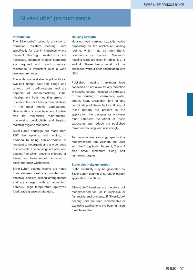
Housing strength
Housing load carrying capacity varies
depending on the application loading
regime, which may be intermittent,
continuous or cyclical. Maximum
housing loads are given in tables 1, 2, 3
and 4. These loads must not be
exceeded without prior consultation with
NSK.
Published housing maximum load
capacities do not allow for any reduction
in housing strength caused by exposure
of the housing to chemicals, water,
steam, heat, ultraviolet light or any
combination of these factors. If any of
these factors are present in the
application the designer or end-user
must establish the effect of these
exposures and reduce the published
maximum housing load accordingly.
To maximise load carrying capacity it is
recommended that washers are used
with the fixing bolts. Tables 1, 2 and 3
also detail maximum fixing bolt
tightening torques.
Static electricity generation
Static electricity may be generated by
Silver-Lube® bearing units under certain
application conditions.
Silver-Lube® bearings are therefore not
recommended for use in explosive or
flammable environments. If Silver-Lube®
bearing units are used in flammable or
explosive applications the bearing insert
must be earthed.

RHP Maximum housing load (N) at 20°Cdesignation
P1 P1 P1 P2 P2 P2 P3 P3 P3Intermittent Continuous Cyclical Intermittent Continuous Cyclical Intermittent Continuous Cyclical
loading loading loading loading loading loading loading loading loading
| 98
Housing strength
Table 1 PNP Silver-Lube® pillow block - housing load capacity
F1
F2
PSF SERIES
U
PST SERIES
PNP20CR 3500 1700 800 2800 1400 800 2600 1300 700PNP3⁄4CR 3500 1700 800 2800 1400 800 2600 1300 700PNP25CR 4000 2000 1000 3100 1500 800 2600 1300 700PNP1CR 4000 2000 1000 3100 1500 800 2600 1300 700PNP30CR 5000 2500 1200 3500 1800 1000 4000 2000 1100PNP13⁄16CR 5000 2500 1200 3500 1800 1000 4000 2000 1100PNP11⁄4RCR 5000 2500 1200 3500 1800 1000 4000 2000 1100PNP35CR 6000 3000 1500 4300 2100 1200 4100 2100 1100PNP11⁄4CR 6000 3000 1500 4300 2100 1200 4100 2100 1100PNP17⁄16CR 6000 3000 1500 4300 2100 1200 4100 2100 1100PNP40CR 10700 5300 2900 8000 4000 2200 6800 3400 1900PNP11⁄2CR 10700 5300 2900 8000 4000 2200 6800 3400 1900
RHP Maximum housing load (N) at 20°C Maximum fixing designation bolt torque (Nm)
F1 F1 F1 F2 F2 F2Intermittent Continuous Cyclical Intermittent Continuous Cyclical
loading loading loading loading loading loading
Table 2 PSF Silver-Lube® four-bolt flange - housing load capacity
PSF20CR 3100 1600 900 1300 700 400 18PSF3⁄4CR 3100 1600 900 1300 700 400 18PSF25CR 3500 1700 1000 1300 700 400 25PSF1CR 3500 1700 1000 1300 700 400 25PSF30CR 4600 2300 1300 2200 1100 600 30PSF13⁄16CR 4600 2300 1300 2200 1100 600 30PSF11⁄4RCR 4600 2300 1300 2200 1100 600 30PSF35CR 6200 3100 1700 2600 1300 700 35PSF11⁄4CR 6200 3100 1700 2600 1300 700 35PSF17⁄16CR 6200 3100 1700 2600 1300 700 35PSF40CR 6200 3100 1700 4000 2000 1100 40PSF11⁄2CR 6200 3100 1700 4000 2000 1100 40
RHP Maximum housing load (N) at 20°Cdesignation
U U UIntermittent loading Continuous loading Cyclical loading
Table 4 PST Silver-Lube® take-up - housing load capacity
PST20CR 5700 2800 1600PST3⁄4CR 5700 2800 1600PST25CR 5400 2700 1500PST1CR 5400 2700 1500PST30CR 8100 4000 2300PST13⁄16CR 8100 4000 2300PST11⁄4RCR 8100 4000 2300PST35CR 7800 3900 2200PST11⁄4CR 7800 3900 2200PST17⁄16CR 7800 3900 2200PST40CR 8100 4000 2300PST11⁄2CR 8100 4000 2300
Note that there is no maximum fixing bolt torque applicable for take-up units.
Maximum housing load (N) at 20°C Maximum fixingbolt torque (Nm)
P4 P4 P4Intermittent Continuous Cyclical
loading loading loading
| 99
SILVER-LUBE® PRODUCT RANGE
P3
P2
P1
P4
PNP SERIES
T3
T2
T1
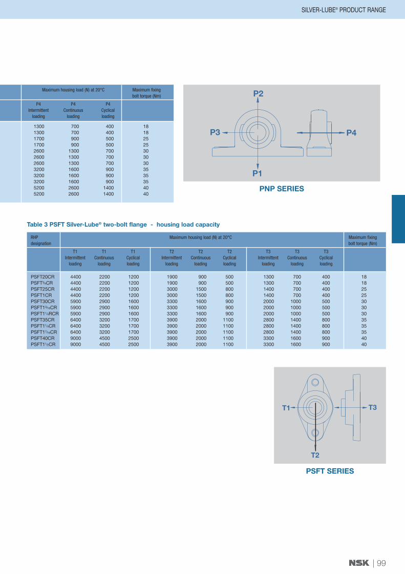
PSFT SERIES
1300 700 400 181300 700 400 181700 900 500 251700 900 500 252600 1300 700 302600 1300 700 302600 1300 700 303200 1600 900 353200 1600 900 353200 1600 900 355200 2600 1400 405200 2600 1400 40
RHP Maximum housing load (N) at 20°C Maximum fixing designation bolt torque (Nm)
T1 T1 T1 T2 T2 T2 T3 T3 T3Intermittent Continuous Cyclical Intermittent Continuous Cyclical Intermittent Continuous Cyclical
loading loading loading loading loading loading loading loading loading
Table 3 PSFT Silver-Lube® two-bolt flange - housing load capacity
PSFT20CR 4400 2200 1200 1900 900 500 1300 700 400 18PSFT3⁄4CR 4400 2200 1200 1900 900 500 1300 700 400 18PSFT25CR 4400 2200 1200 3000 1500 800 1400 700 400 25PSFT1CR 4400 2200 1200 3000 1500 800 1400 700 400 25PSFT30CR 5900 2900 1600 3300 1600 900 2000 1000 500 30PSFT13⁄16CR 5900 2900 1600 3300 1600 900 2000 1000 500 30PSFT11⁄4RCR 5900 2900 1600 3300 1600 900 2000 1000 500 30PSFT35CR 6400 3200 1700 3900 2000 1100 2800 1400 800 35PSFT11⁄4CR 6400 3200 1700 3900 2000 1100 2800 1400 800 35PSFT17⁄16CR 6400 3200 1700 3900 2000 1100 2800 1400 800 35PSFT40CR 9000 4500 2500 3900 2000 1100 3300 1600 900 40PSFT11⁄2CR 9000 4500 2500 3900 2000 1100 3300 1600 900 40

Basic bearing Bearing limiting ISO h7 Shaft tolerance ISO h7 Shaft tolerance Bearing limiting ISO h9 Shaft tolerance ISO h9 Shaft toleranceinsert speed (RPM) high (0.001 mm Units) low (0.001 mm Units) speed (RPM) high (0.001 mm Units) low (0.001 mm Units)
RHP Weightdesignation Bore dia D C B S r M Cr (N) Cor (N) (Kg)
| 100
Silver-Lube® bearing inserts
SILVER-LUBE® PRODUCT RANGE
Silver-Lube® bearing inserts have martensitic stainless steel rings and balls,
and austenitic stainless steel ball cage, flingers and set screws.
The grease in this product is an aluminium complex food grade grease, classified to
NSF grade H1. In the event of relubricating being necessary, this type of grease is the
first choice replacement.
If an aluminium complex food grade grease is not available, it is essential that any
alternative grease is NSF H1 approved and ideally chemically compatible with the
original grease. If chemical compatibility cannot be assured, then it is recommended
that the original grease is completely flushed out of the system before relubrication.
NSK should be consulted where necessary.
D
Radius r
C
S S1
B
Mh
Shaft tolerances and permissible speeds
Bearing insert permissible speed is dependent on shaft tolerance. For higher speed
applications an ISO h7 shaft tolerance is recommended. An ISO h9 shaft tolerance may
be used for low speed applications. For more information see table 6.
Table 6 Tolerances and speeds
Table 5 Insert designations, dimensions and weights
J1020-20GCR 20 47 16 31.0 12.7 1.5 5.0 9910 5350 0.16J1020-3⁄4GCR 3⁄4'' 47 16 31.0 12.7 1.5 5.0 9910 5350 0.16J1025-25GCR 25 52 17 34.0 14.3 1.5 5.5 10820 6300 0.20J1025-1GCR 1'' 52 17 34.0 14.3 1.0 5.5 10820 6300 0.20J1030-30GCR 30 62 19 38.1 15.9 1.5 6.0 15000 9050 0.32J1030-13⁄16GCR 13⁄16'' 62 19 38.1 15.9 1.0 6.0 15000 9050 0.32J1030-11⁄4GCR 11⁄4'' 62 19 38.1 15.9 1.0 6.0 15000 9050 0.32J1035-35GCR 35 72 20 42.9 17.5 2.0 6.5 19820 12300 0.48J1035-11⁄4GCR 11⁄4'' 72 20 42.9 17.5 2.0 6.5 19820 12300 0.48J1035-17⁄16GCR 17⁄16'' 72 20 42.9 17.5 1.5 6.5 19820 12300 0.48J1040-40GCR 40 80 21 49.2 19.0 2.0 8.0 22540 14300 0.64J1040-11⁄2GCR 11⁄2'' 80 21 49.2 19.0 2.0 8.0 22540 14300 0.64
J1020 2900 0 -21 1490 0 -52J1025 2600 0 -21 1300 0 -52J1030 2180 0 -21 1090 0 -52J1035 1870 0 -25 940 0 -62J1040 1650 0 -25 830 0 -62
Units: mm

Bearing Designation Maximum tighteningdesignation of set screws torque (Nm)
| 101
Materials and tightening torques
SILVER-LUBE® PRODUCT RANGE
Set screw tightening torques
Set screws for Silver-Lube® bearing inserts are manufactured from stainless steel and
can fracture if overtightened. The limiting set screw torques listed (in Table 7) should
not be exceeded.
Table 7 Recommended tightening torques for set screws
Materials
Parts Materials
Bearing Rings Martensitic stainless steel (equivalent to SUS440C)
Ball Martensitic stainless steel (equivalent to SUS440C)
Bearing Flinger Austenitic stainless steel (equivalent to SUS302)
Set Screw Martensitic stainless steel (equivalent to SUS304)
Cage Austenitic stainless steel (equivalent to SUS302)
Bearing housing Thermo Plastic PBT
J1020-20GCR M6 X 6.0 LONG 4J1020-3⁄4GCR M6 X 6.0 LONG 4J1025-25GCR M6 X 6.0 LONG 4J1025-1GCR M6 X 6.0 LONG 4J1030-30GCR M6 X 6.0 LONG 4J1030-13⁄16GCR M6 X 6.0 LONG 4J1030-11⁄4GCR M6 X 6.0 LONG 4J1035-35GCR M8 X 8.0 LONG 8J1035-11⁄4GCR M8 X 8.0 LONG 8J1035-17⁄16GCR M8 X 8.0 LONG 8J1040-40GCR M8 X 8.0 LONG 8J1040-11⁄2GCR M8 X 8.0 LONG 8

Shaft RHP designation Basic Housing Dimensions (mm)diameter bearing group
insert
L H H1 H2 Jmm inches
| 102
Unit dimensionsTable 8
PNP Silver-Lube® pillow block - unit dimensions
20 PNP20CR J1020 2 127.2 33.3 14.2 65.9 94.93⁄4 PNP3⁄4CR J1020 2 127.2 33.3 14.2 65.9 94.9
25 PNP25CR J1025 3 140.2 36.5 14.5 71.9 104.91 PNP1CR J1025 3 140.2 36.5 14.5 71.9 104.9
30 PNP30CR J1030 4 162.2 42.9 17.8 83.9 118.913⁄16 PNP13⁄16CR J1030 4 162.2 42.9 17.8 83.9 118.911⁄4 PNP11⁄4RCR J1030 4 162.2 42.9 17.8 83.9 118.9
35 PNP35CR J1035 5 167.2 47.6 18.0 94.9 126.911⁄4 PNP11⁄4CR J1035 5 167.2 47.6 18.0 94.9 126.917⁄16 PNP17⁄16CR J1035 5 167.2 47.6 18.0 94.9 126.9
40 PNP40CR J1040 6 184.2 49.2 19.5 98.9 136.811⁄2 PNP11⁄2CR J1040 6 184.2 49.2 19.5 98.9 136.8
All dimensions in mm except inch shaft sizes

Dimensions (mm) Weight
N N1 G A A1 B Skg
| 103
SILVER-LUBE® PRODUCT RANGE
PNP SERIES
H2
H1
G Bolt DiaH
JL
N
A1
A
BN1
S
11.0 14.2 M10 37.8 22.5 31.0 12.7 0.2711.0 14.2 M10 37.8 22.5 31.0 12.7 0.27
11.0 14.2 M10 37.8 24.5 34.0 14.3 0.3911.0 14.2 M10 37.8 24.5 34.0 14.3 0.39
14.0 18.2 M12 45.8 27.0 38.1 15.9 0.5214.0 18.2 M12 45.8 27.0 38.1 15.9 0.5214.0 18.2 M12 45.8 27.0 38.1 15.9 0.52
14.0 18.2 M12 47.8 32.5 42.9 17.5 0.7214.0 18.2 M12 47.8 32.5 42.9 17.5 0.7214.0 18.2 M12 47.8 32.5 42.9 17.5 0.72
14.0 18.2 M12 53.8 36.0 49.2 19.0 0.9914.0 18.2 M12 53.8 36.0 49.2 19.0 0.99

Shaft RHP designation Basic Housing Dimensions (mm)diameter bearing group
insert
L J Gmm inches
| 104
Unit dimensionsTable 9
PSF Silver-Lube® four-bolt flange - unit dimensions
20 PSF20CR J1020 2 86.5 63.5 M103⁄4 PSF3⁄4CR J1020 2 86.5 63.5 M10
25 PSF25CR J1025 3 95.0 70.0 M101 PSF1CR J1025 3 95.0 70.0 M10
30 PSF30CR J1030 4 107.5 83.0 M1213⁄16 PSF13⁄16CR J1030 4 107.5 83.0 M1211⁄4 PSF11⁄4RCR J1030 4 107.5 83.0 M12
35 PSF35CR J1035 5 117.5 92.0 M1211⁄4 PSF11⁄4CR J1035 5 117.5 92.0 M1217⁄16 PSF17⁄16CR J1035 5 117.5 92.0 M12
40 PSF40CR J1040 6 130.5 102.0 M1211⁄2 PSF11⁄2CR J1040 6 130.5 102.0 M12
All dimensions in mm except inch shaft sizes

Dimensions (mm) Weight
A A1 A1 B Skg
| 105
SILVER-LUBE® PRODUCT RANGE
PSF SERIES
G Bolt Dia
J
L A1AA4
SB
27.8 36.3 13.4 31.0 12.7 0.2827.8 36.3 13.4 31.0 12.7 0.28
27.9 36.7 14.3 34.0 14.3 0.3427.9 36.7 14.3 34.0 14.3 0.34
31.5 41.4 14.3 38.1 15.9 0.5031.5 41.4 14.3 38.1 15.9 0.5031.5 41.4 14.3 38.1 15.9 0.50
34.8 46.9 15.5 42.9 17.5 0.7434.8 46.9 15.5 42.9 17.5 0.7434.8 46.9 15.5 42.9 17.5 0.74
37.5 53.2 17.1 49.2 19.0 0.9837.5 53.2 17.1 49.2 19.0 0.98

Shaft RHP designation Basic Housing Dimensions (mm)diameter bearing group
insert
L H Jmm inches
| 106
Unit dimensionsTable 10
PSFT Silver-Lube® two-bolt flange - unit dimensions
20 PSFT20CR J1020 2 64.1 113.3 90.03⁄4 PSFT3⁄4CR J1020 2 64.1 113.3 90.0
25 PSFT25CR J1025 3 68.4 130.3 99.01 PSFT1CR J1025 3 68.4 130.3 99.0
30 PSFT30CR J1030 4 80.1 148.3 117.013⁄16 PSFT13⁄16CR J1030 4 80.1 148.3 117.011⁄4 PSFT11⁄4RCR J1030 4 80.1 148.3 117.0
35 PSFT35CR J1035 5 90.1 163.3 130.011⁄4 PSFT11⁄4CR J1035 5 90.1 163.3 130.017⁄16 PSFT17⁄16CR J1035 5 90.1 163.3 130.0
40 PSFT40CR J1040 6 100.1 175.3 144.011⁄2 PSFT11⁄2CR J1040 6 100.1 175.3 144.0
All dimensions in mm except inch shaft sizes

Dimensions (mm) Weight
G A A1 A4 B Skg
| 107
SILVER-LUBE® PRODUCT RANGE
PSFT SERIES
H
G BoltDia
J
L
A1
AA4
SB
M10 26.5 33.7 11.4 31.0 12.7 0.24M10 26.5 33.7 11.4 31.0 12.7 0.24
M10 29.1 36.7 13.4 34.0 14.3 0.30M10 29.1 36.7 13.4 34.0 14.3 0.30
M10 30.5 41.2 13.4 38.1 15.9 0.44M10 30.5 41.2 13.4 38.1 15.9 0.44M10 30.5 41.2 13.4 38.1 15.9 0.44
M12 32.8 43.4 16.1 42.9 17.5 0.64M12 32.8 43.4 16.1 42.9 17.5 0.64M12 32.8 43.4 16.1 42.9 17.5 0.64
M12 37.5 51.7 20.0 49.2 19.0 0.89M12 37.5 51.7 20.0 49.2 19.0 0.89

Shaft RHP designation Basic Housing Dimensions (mm)diameter bearing group
insert
L L1 L4 H H1mm inches
| 108
Unit dimensionsTable 11
PST Silver-Lube® take up units - unit dimensions
20 PST20CR J1020 2 99.0 64.0 47.0 88.0 35.03⁄4 PST3⁄4CR J1020 2 99.0 64.0 47.0 88.0 35.0
25 PST25CR J1025 3 99.0 64.0 47.0 88.0 35.01 PST1CR J1025 3 99.0 64.0 47.0 88.0 35.0
30 PST30CR J1030 4 125.0 76.0 63.0 102.0 40.013⁄16 PST13⁄16CR J1030 4 125.0 76.0 63.0 102.0 40.011⁄4 PST11⁄4RCR J1030 4 125.0 76.0 63.0 102.0 40.0
35 PST35CR J1035 5 125.0 76.0 63.0 102.0 40.011⁄4 PST11⁄4CR J1035 5 125.0 76.0 63.0 102.0 40.017⁄16 PST17⁄16CR J1035 5 125.0 76.0 63.0 102.0 40.0
40 PST40CR J1040 6 140.0 85.0 80.0 114.0 40.011⁄2 PST11⁄2CR J1040 6 140.0 85.0 80.0 114.0 40.0
All dimensions in mm except inch shaft sizes

Dimensions (mm) Weight
H3 G G1 A A1 A2 B Skg
| 109
SILVER-LUBE® PRODUCT RANGE
PST SERIES
A2
H3
G Thread
H
L
A1A
L1
G1
B
S
L4
H1
75.8 M16X2.00 22.5 27.5 24.5 12.2 31.0 12.7 0.3275.8 M16X2.00 22.5 27.5 24.5 12.2 31.0 12.7 0.32
75.8 M16X2.00 22.5 27.5 24.5 12.2 34.0 14.3 0.3675.8 M16X2.00 22.5 27.5 24.5 12.2 34.0 14.3 0.36
88.8 M16X2.00 22.5 34.5 30.0 12.2 38.1 15.9 0.5388.8 M16X2.00 22.5 34.5 30.0 12.2 38.1 15.9 0.5388.8 M16X2.00 22.5 34.5 30.0 12.2 38.1 15.9 0.53
88.8 M16X2.00 22.5 34.5 30.0 12.2 42.9 17.5 0.7488.8 M16X2.00 22.5 34.5 30.0 12.2 42.9 17.5 0.7488.8 M16X2.00 22.5 34.5 30.0 12.2 42.9 17.5 0.74
101.8 M16X2.00 22.5 34.0 32.0 16.2 49.2 19.0 1.00101.8 M16X2.00 22.5 34.0 32.0 16.2 49.2 19.0 1.00