siemens - electrical part manual s · hard hots. safety glasses or face shields. flash ... this...
TRANSCRIPT

SIEMENS
Static Trip Ill Retrofit for Westinghouse Type DB Low Voltage Power Circuit Breakers
Installation Instructions
. .
;t��jl\��;�*'L ·,;/:�:��tJ;}i�'!litl�]�i��f%';��L,.'�)% · . if1i'0�}�';l'\!:Jg�t,'JI(���f§' •····.•
www . El
ectric
alPar
tMan
uals
. com

Hazardous voltages ore present in the equipment which will cause severe persona l injury ond equipment domo'ile. Always de-energize ond re�move the breaker from 1ts cubicle before maintenance or retrofit work. t.laintenance or retrofit should be perforTT\ed only by qualified personnel. The use of unauthorized ports in the� re�poir of the equipment or tompedng by unquollfled personnel wlll result In dangerous conditions which can cause severe personal Injury or equipment damage. Follow oil safety instruction" contained ht�rein.
WARNING The Power Circuit Breakers discussed in the manual may contain a spring charged mechanism that con cause severe injury. Before workl� on ony breaker assure that the 5pin9 s ort� dischorge�d and tht� contacts ore in the open position. Some procedures may require the breaker to b& closed. In such cases. assure that the contoc:ts ore securely wedged to prevent on inadvertent opening of the brea ker. Remove wedge. open ond discharge the breaker os soon os the procedure� is completed thot re�quirt�o the breaker to be closed.
IMPORTANT lhe information contained herein is general in nature and does not reliev., the UGt�r of the responsibility to uGe 60und proctict�l!il in application, installation. operation, maintenance and retrofit of the equipment purchoGed. Siemens reserves the right lo make� chonge�s in the specifications shown herein or to make improvements ot any time without notice or obligations. Should o conflict arise between the general information contained in this publication and the contents of drawings or supplementary material. the Iotter sha ll toke prect�denct�.
NOTE For the purpose of this manual a quolifled person Is one who is 'fomilior with th<t instollotion. c;on5truc1.ionw o.ssombly ond opcrrotion of the equipment and the ho:rords Involved. In oddlilon. he hos the following quollflcotions: (o) is f"roined ond authorized to de-energize. clear, 9round , ond tog
circu!ts ond equipment in accordance with estab lished safely proctoceG.
(b) hi; troinod In the proper core and use of protective equipment such os rubber gloves. hard hots . safety glasses or face shields. flash clothing, etc.. in accordance with established safety practices.
(c) is trained to perform maintenance and assembly work on low voltage power circuit breakers.
(d) 1s troined ln rendering first old.
SUMMARY "These instructions do not purport to cover all details or variations in equipment, nor to provide for every poss ible contingency to bt� rnet in connection with installation, operation, or maintenance. Should further information be desired or should particular problems arise which ore not covered sufficiently for the purchaser's purposes. the matter Ghould be referred to the local soles office, listed on bock of this instruction guide.
The contents of thls inst ruction manual should not become part o( or modify any prior or existing agreement, commitment. or relationship. The soles contract contains the entire oblig ation of Siemens Enerw &: Automation. Inc. Any statements contained herein do not create new warranties or mO<Iify the existing warranty.
1 www . El
ectric
alPar
tMan
uals
. com

Table of Contents
1 Introduction . . . . . . . . . . . . . . . . . . . . . . . . . . . . . . . . . . . . . . . . . . . . . . . . . . . . . . . . . . . . . . . . . . . . . . . . . . . . . . . . . ... . . 1-1 1.1 Generallnfonnation . . . . . . . . . . . . . . . . . . . . . . . . . . . . . . . . . . . . . . . . . . .. . . . . . . . . . . . . . . . . . . . . 1-1 1.2 Breaker Exclusion . . . . . . .. . . . . . . . . . . . . ... . . . . . . ... . . . . . . . . .. . . ... . . . . . . . . . .. . . . . . . . .. 1-1 1.3 Static Trip ill Retrofit Catalog Number System ... ......... ... . ...... 1-1 1. 4 Static Trip ill Retrofit Kit - contents . . . . . . . . . . . .. . . . . . . . . . . . . .. . . . . . . . . . . . 1-4 1.5 Kit Identification ........... ................................ ...... . . .................. 1-4
2 Retrofit Kit Assembly . . . . . . . .. . . . . . . . . . . . . . . . . . . . . . . . . . . . . . .. . . . . .. . . . . . .. . . . .. . . . . . . . . . . . . . 2-1 2.1 Danger and Warning Infonnation ..... ... .. ................ .......... ..... .... 2-1 2.2 Assembly Instructions . . . . . . . . . . . . .. . . .. . . . . . . . . .. . . ... . . .. . ... . . . . .. . . . . .. . . . . . . . . . 2-1
2.2.1 Instructions for Sensors and Basic Trip Unit Kit ... ... ... . . 2-1 Installation
2.2.2 Instructions for Cubicle Mount� ............. .. .. ... . ......... .. . 2-24 Communications Disconnect Installation
2.2.3 Instructions for Breaker Display Unit Installation .. . ...... 2-28
3 Breaker Testing and Breaker Labeling . . . . . . . . . .. . .... ...... ....... ............... 3-1 3.1 General Test Description ..................... . . .................................. 3-1 3.2 Testing ......... . . . ........................................................................ 3-1 3.3 Low Frequency Withstand Test ......................... . ...................... 3-1 3.4 Trip Unit Test ............... ........... ............................................... 3-3 3.5 Labeling ......... ... . ..... ............. ... . . . ....... .......... .......................... .. 3-3
11 www . El
ectric
alPar
tMan
uals
. com

1 Introduction
1 Introduction This manual is intended for mechanics with breaker experience, to guide them in retrofitting Westinghouse type DB and DBL breakers with Static Trip m trip units, its associated trip circuit components and auxiliary devices.
This manual does not replace other Siemens manuals covering detailed information, installation, operation or maintenance of the equipment discussed in this manual. Be sure to completely read and understand Danger, Warnings and other Important Notices on the page preceding the "Table of Contents" before you attempt any procedures described in this manual.
1.1 General Information Static Trip m Retrofit Kits contain all materials needed, including hardware and drilling fixtures to retrofit Westinghouse type DB and DBL Low Voltage Power Circuit Breakers with Static Trip ill trip units and their auxiliary components.
Unless otherwise specified, Static Trip ill retrofit components are packaged in one cardboard box per breaker. Each box contains factory assembled and factory wired assemblies required for installation on the breaker. These assemblies are assembled and wired up to the point required to installation on breaker. The assemblies and parts contained in each box are according to the kit catalog number you have specified.
1.2 Breaker Exclusion The Static Trip ill Retrofit Kit will not fit with all accessories available on the original Westinghouse breakers. • For breaker with Under Voltage Relays, the Static Trip m Retrofit Kit cannot be used. • For breakers with Bell Alarm, consult factory.
1.3 Static Trip ill Retrofit Catalog Number System Table 1.1 illustrates the catalog number system for Static Trip m Retrofit Kits. As _s_!town in the table on the following page, trip unit models are identified by a three digit code number. Table 1.2 tells what functions each model contains.
In the event you prefer a different trip unit model other than you had specified or received inadvertently, use the eleven-digit trip unit part number of Table 1.2 for ordering purpose.
1- 1 www . El
ectric
alPar
tMan
uals
. com

j 1 I .L
Example:
Catalog Number ST ill Retrofit Kits
K designate "kit"
Breaker Type
J DBU = Type DB unfused DBL = Type DBL fused
Breaker Frame Size 025 = 600 amps
050 = 1600 amps
075 = 3000 amps 100 = 4000 amps
Static Trip ID Model
DBU
See Table 1.2 for code identification
Sensor Type A =
T =
D =
Standard (single winding) Tapped winding Dual winding with 2000A NEC ground winding
Sensor Rating 01 = 1 50 amps
02 = 200 amps
40 = 4000 amps
Breaker Display Unit 0 = Not included 1 = Included
Standard I Special A = Standard S = Special order
Table 1 .1 Catalog Numbering System
1 Introduction
- 0
1-2 www . El
ectric
alPar
tMan
uals
. com

1 Introduction
X Protective Relaying P - Power Metering N- Neutral Current Metering C = Communications Capability Z = Zone Jnterl� Canabilitv T- LCD Thrgets/Watchdog Circuit G = Ground Fault I Instantaneous s Short Time T = Long Time 1-
Type Trip Unit T s I G T z c N p X 18486-924- Code Nwnber
Basic Trip Units T I T -504 with Targets T s T z -505
T s I T z -506 T I G T z -507 T s G T z -508 T s I G T z -509
Trip Units T I T c -510 with T s T z c -511
Communications T s I T z c -512 T I G T z c -513
Breaker c T s G T z c -514 Display T s I G T z c -515
Unit Trip Units T I T c p X -546
Optional with T s T z c p X -547 Comm., Power T s I T z c p X -548
Metering and T I G T z c p X -549 Prot Relaying T s G T z c p X -550
CPX T s I G T z c p X -551
Table 1.2 Static Trip ill Unit Code Numbers
1-3 www . El
ectric
alPar
tMan
uals
. com
J .
1 Introduction
1.4 Static Trip ill Retrofit Kit - Contents Definition: "Static Trip ill Retrofit Kit":
One container consisting of factory assembled and factory wired assemblies, as specified per Static Trip Retrofit Kit Catalog Number, as needed to retrofit � breaker.
All Static Trip ill Retrofit Kits (Trip Unit code numbers 504 through 515 and 546 through 551) include the following:
a) trip unit kit - factory wired and assembled kit including • Static Trip ill unit • trip actuator • bus splice bars (DB-25, DBL-25, DB-50, & DBL-50 only)
b) sensors
Communications trip units without the power metering or protective relaying options, (Trip Unit code numbers 510 through 515) include the following additional items:
c) communications disconnect (breaker mounted umbilical cable) d) communications disconnect (for mounting in cubicle).
Trip units with power metering or protective relaying options, (Trip Unit code numbers 546 through 551) include the following additional items:
e) potential transformer module and fuses - factory wired and assembled with basic trip kit.
Note that the Breaker Display Unit (BDU) requires Static Trip ill units with communications capability. The BDU is included if specified in the Kit Catalog Number and provided that the trip unit model selected includes communications.
1.5 Kit Identification Each Static Trip ill Retrofit Kit is labeled on the outside of its cardboard box with-the catalog number and a brief description of the sub kits included. Each kit also includes a bill of material, listing all sub kits by name and part number.
Each sub kit is labeled with its part number. In addition, a bill of material inside the enclosure of each sub kit allows you to verifY the contents of each sub kit.
1-4
www . El
ectric
alPar
tMan
uals
. com

2 Retrofit Kit Assembly
Figure 2.2 Rear View of DB-25 Breaker (DB-50 similar)
2-3 www . El
ectric
alPar
tMan
uals
. com

2 Retrofit Kit Assembly
Figure 2.3 Front View of DB-100 Breaker (DB-75 similar)
2-4 www . El
ectric
alPar
tMan
uals
. com
2 Retrofit Kit Assembly
Figure 2.4 Rear View of DB-100 Breaker (DB-75 similar)
2-5 www . El
ectric
alPar
tMan
uals
. com

2 Retrofit Kit Assembly
Figure 2.5 DB-25 Kit Bill-of-Material - p/n 18-824-921-5xx
503 502 501 U/H l"TEH DESCFIIPTJON PART NO. REMARKS QTY QTY QTY
J l l E:A 1 SHELF 18 754 765 COl
I 1 1 EA 2 062� ACTUATOR ASSY 1 6-7!54 763 !501
J 1 1 EA 3 MECHANSIM lOP PlATE 1 8-658- 1 -45-286
5 2 c EA ... SCR #10-32 Y . 5 15-171 399 010 ... �cn"'t', ... lf[W 'U
2 2 2 EA 5 BUSHING co 855-517 051
29 29 29 fT (s WIRE f18 SIS 00-55 7-286 003
7 7 7 EA 7 T[RUINAL #10 RING 1 5 172 099 00:5 PlJC[ IN &tC. ft'[W 14
3 3 3 EA 9 CABL£ SLEEVING 1 5-17 1 054 011
4 .. .. EA 10 TERUINAL #6 RING 15 172 099 001
4 4 4 EA 1 1 #10 L/W 00-655 067-100 4 4 4 EA 12 SCR # 10 32 y .2� 00 615 245 214
JO 8 6 EA 1 3 TYRAP 00-857-271 100 OUoCt ""' s ... .-c. ., .. t.c
1 l l EA 1-4 PLASTIC BAG 15-171 004 041
1 EA 15 LABEL ' 18-75, -783-038 Dl.AC'tC""� ntW 14
3 EA 17 f/10 32 STOP NUT oo-633 059-210
2 EA 15 #10 f"LAT WASHER 00 651 007 057
3 3 3 EA 1 9 BUS LINK 1 6 661 621 001 f1[W 1" 3 3 3 EA 20 BUS SHIU 18 661 622 001
"'-ACt ... .....,. " ,.
1 1 EA 21 COMI.IUNICATION WIRE HARNESS 18-398-289-564
1 1 EA 22 BREAKER POSITION SwrTCH co 000 466 771
1 1 EA 23 UOUN'TING ANGLE 18-658 lAS 289
2 2 EA 24 SCR IS 32 " 1 oc 615 -471 161
6 6 "' EA 25 (/ 8 32 NUT 00 631-109 108
6 6 "' EA 26 f/8 EXT TOOTH L/W oc 655 067 080
4 4 4 EA 27 SCR #8-32 >< 1 /:Z oo-615 471-174
J 1 E:A 28 INSULATOR 18 658 110 126
::I 3 1 EA 29 PUSH IN CLEAT 1!5 172 791 027
J EA 3� PT MODULE 18 517 538 501
2 EA 34 SCR f/10 32 y 1 co 615 -485 225
J EA 35 f"USEBLOCK 77 901 001 029
J EA 3(s OIN RAIL 25 135 714 C06
3 EA 37 I" USE 15-172-704-002
2 EA 38 SCR #S 32 v .25 w; LW co 615 6-41-904
10 FT 39 WIRE HI TEUP 1 5 172 756 010
3 EA -40 TERMINAL SPADE 1 5 172 099 022 PUC[ ......... '"'" ...
J E A -41 4 PIN CONNECTOR Hi 6:58 1-43 o:;e E A
................. 2 -42 TYRAP liE DOWN 25-1� 1 81-001 ...... ,.
l EA -43 INSULATOR 1- 00 871 311 109
2 EA .... SCR 1/A-:10 " 1 /2 HEX W/ L/W 00 611 A35 371
J EA o4(s LABEL 18 751-7$3 039 ........
J EA 47 LABEL 15 751 753-040 ova""""' ...... ,.
YES YE S YES EA -48 LABEL 1 8 658 1-45 293 -� YES YES YES EA 49 STATIC TRIP Ia 18-486--47�- -
YES YES YES EA 50 PRINT 1 8 624 921 503 ...... ,.
6 6 6 EA 51 BOLT. G:S • • �-1:5 " 2.:5 00 611 31� �6 ,.._ .. -"DDU
Jc l2 12 EA 52 f"LATWASHER co 651 007 300 ....a .. -........
6 6 6 EA 53 NUT, 1/2 co (s31 059 108 ........
6 6 6 EA SA L/W 00 655 017 036 ova: .. -........
L' t-a_ E :"!::: � c ::£ (.) E
0 :5 '(ii
0 j: 0 (.__) OJ
2-6 www . El
ectric
alPar
tMan
uals
. com

2 Retrofit Kit Assembly
Figure 2.6
GN IA!MC£115 -1 CIPEIW'[ II C-WIA[ S\'S1Eioll. -CI N[lOitll (iN "' UCoOl\[ 1€0(.
DB-25 Kit Assembly PIX
1-----------1.3.00-------------1 C)N-.u<D!Sl .... -D.I1[ Ill ]...WO( -["6. 8CI.41[ 11€ N[- .. -CIIIC! M(ll[
� -Tr�IU
D---o ....=:c..=:o --o
DEPTH 4.63 IN
l[RII 1 - BROWN
2- REO J- ORANGE 4 - All STRIPPED 'IMR[S INSTAll S'llr11CH 'llr11H PLIJNGER (;\ TOWARDS BR[AK[R �
7.75
4 .50
34
2-7 www . El
ectric
alPar
tMan
uals
. com

2 Retrofit Kit Assembly
Figure 2.7 DB-50 Kit Bill-of-Material - p/n 18-824-922-Sxx
503 SOc 501 U/H ITEH DESCRlPTlDN PART NO. REMARKS O'TY O'TY O'TY
1 1 1 EA 1 SHELF 18 7�4 773 001
1 1 1 EA 2 0850 ACTUATOR AssY 18 755-736 SOl
l l l EA 3 t.AECHANSit.A 'TOP PLATE 1 8 658 145-296 5 <? <? EA 4 SCR 1/10 32 l< .5 15 1 71 399 010
2 2 2 EA 5 BUSHING co 555 517 051 29 28 29 rT 6 WIRE 1/18 SIS 00 557 286 003
7 7 7 EA 7 'TERMINAL 1/10 RING 15 172 099 003 n[W U .
J 1 1 E A B DRILL TEt.APLATE IS 658 669 584 ......,. ........ rT!:W \4
.3 .3 .3 EA 9 CABLE SLEEVE 15 1 71 054- 011
4 4 4 EA 10 'TERMINAL 1/6 RING 15 172 099-001 4 "' 4 EA 11 #10 L/W 00 655 067-100
4 4 4 EA 12 SCR 110-32 lC .25 oo-615 245 214
10 8 6 EA 13 TYRAP 00 557 271-100 ..._..,.orr • tN 8ACh nrw , ..
1 1 1 EA 14 PLASTIC BAG 1� 171 004 041
1 EA 15 LABEL IS 751 783-042 nt:W 14
3 EA 17 #10 .32 STOP NUT 00 6.3.3 059 210
2 EA 18 #10 F'LA1 WASHER 00 651 007 087 3 3 J EA 19 BUS LINK 18 661 623 001 ..._..,. IN 8"4
RfW 14
1 1 EA 21 COt.AI.AUNICATION WIRE HARNESS 16 396 269 564 1 1 EA 22 BREAKER POSITION SWITCH 00 000-466 771 1 1 EA 23 t.AOUN'TING ANGLE 18 661 620-001
2 2 EA 24 SCR 1/8-32 >< 1 co 615 471-181
6 8 4 EA 25 1/8 32 NU'T 00 631 109 108 a 8 4 EA 26 #8 EXT TOOTH L/W 00 655 067 080 6 6 4 EA 27 SCR IS 32 x 1/2 00 615 471 174 1 J EA 28 INSULA'TOR 18 655 110 126
:1 3 1 EA 29 PUSH IN CLEAT 1!:)-172 791-027
1 EA 33 PT MODULE 18 817 538 501
2 EA 34 SCR 1/10 32 " 1 00 615 485 225
1 EA 35 F'USEBLOCK 77 901 001 029
I EA 36 DIN RAIL 25-135-714-006 3 EA 37 FUSE 1!:) 172 704 002
2 [A 38 SCR IS 32 l< .25 W/ LW 00 615 641-904
12 F'T 39 WIRE HI 'TEUP 15 172 756 010
.3 EA 40 'TERMINAL SPAOE 15 172 099 022 ntw u I EA 41 4 PIN CONNEC'TOR 1 8 655 1 43-058
2 EA 42 lYRAP 'TIE DOWN 2!:1 13� 181 001 "'l....tC[tli� n(W 14
1 EA 43 INSULATOR t• co 871 311-109
2 EA 44 SCR 1/4 20 " 1/2 HEX W/ L/W 00 611 435-371
1 EA 46 LABEL 18 751 783-043 nt:W 1_.,
1 EA 47 LABEL 18 751 783 044 �� ('M 8114 nt:w 14
YES YES YES EA 48 LABEL 15 658 145 293 c.tu.fO rc;.ft ca1 OAO(AIN<:-
YES YES YES EA 49 STATIC TRIP In 18 486 475 """""'"" .,_.... YES YES YES EA 50 PRIN'T 18 824 922 -503
�ltN..O n[W 14
12 12 12 EA 51 BOLT. C5, .5-13 " 3.0 00 611 315 560 ' new u
.?4 24 24 EA 52 F'LAlWASHER co 651 007 300 Jll.IC( IN ..0:
ntW 14
J2 12 12 EA 5.3 NUT, 1/2 co 6.31 059 108 ........C[ tN8o'G.
new •• 1<? 1<? 12 EA 54 L/W 00 65-5 017 036 nt:w ·u.
,ell
h:: E -� 0 S:Z
u E () £ "(i'i 0 3: 0 u lD
2-8
www . El
ectric
alPar
tMan
uals
. com

2 Retrofit Kit Assembly
Figure 2.8 DB-50 Kit Assembly PIX
H[O[
DEPTH
t----.,-cw.,..,_=,os�-�------17.50-------------l � .. ,_liM[
TEN 1 - Bf!CWN 2- REO .3 - ()R.ON(;[
---
• - All STRIPP[O WIRES
�!l'olc....,lll
D .. --o �0 --o
�� �
2-9 www . El
ectric
alPar
tMan
uals
. com
2 Retrofit Kit Assembly
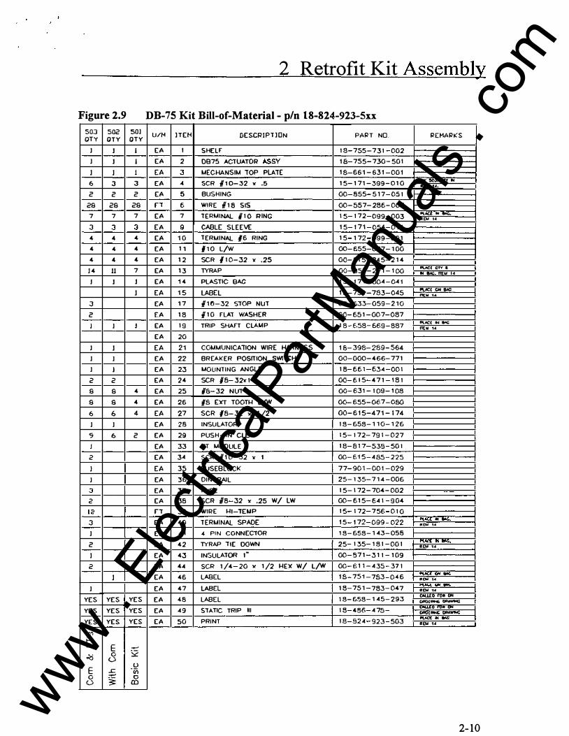
Figure 2.9 DB-75 Kit Bill-of-Material - p/n 18-824-923-Sxx
503 502 501 U/H lTEH DESCRIPTJON PART NO. REHARKS QTY Q T Y Q T Y
J 1 I EA 1 SHELF 18 755-731 002
I 1 I EA 2 0875 ACTUATOR ASSY 18 755 730-501
1 1 I EA 3 MECHANSIM TOP PLATE 1$ 661-631 001
6 3 3 EA .c SCR ,V10-32 " .5 15-171-399-010 IIUC'��W •01 1.1.
c c c EA 5 BUSHING 00 855 517 051
29 29 29 n 6 WIRE 118 SIS 00-557-286-003
7 7 7 EA 7 TERMINAL 1/10 RING 15 172 099 003 P\AU .. flAG.. ft'[).l 1 ..
3 3 3 EA 9 CABLE SLEEVE 15 171 054 011
4 4 4 EA 10 TERMINAL #6 RING 15 172 099 001
4 4 4 EA 11 flO L/W 00 655 067 100
4 4 4 EA 12 SCR /10-32 lC .25 00-615-245-214
J4 11 7 EA 13 TYRAP 00-857-271-100 PUC[ CT'f 4 II 81(; 11[U , ..
1 1 1 EA 14 PLASTIC BAG 15-171-004-041
J EA 15 LABEL 18 751 783 045 IVC[ ON SAC nt:w t<4
3 EA 17 110-32 STOP NUT 00-633-059-210
c f. A 18 I 10 FLAT WASHER 00-651-007-087
I I 1 EA 19 TRIP SHAFt CLAMP 18 E--58 6€9 887 11\.,f(:[ .., B.tC: rt(W 1.4
EA 20
J J EA 21 COMMUNICATION WIRE HARNESS 18-398-289-564
I I EA 22 BREAKER POSITION SWITCH 00-000-466-771
I I EA 23 I.AOUNTING ANGLE 18 661 634 001
2 2 EA 24 SCR #8 32><1 00 ISIS 471 1 81
9 9 4 EA 25 #f:i-32 NUT 00-631-109-108
9 s 4 EA 26 fS EXT TOOTH L/W 00- 655-0€7-080 6 6 4 EA 27 SCR #8-32 X 1 /2 00-615-471-174
I I EA 28 INSULATOR 18-658-110-126
c; 6 c EA 29 PUSH-IN CLEAT 15-172-791-027
J EA 33 PT I.AOOULE 18 817 535 501
2 EA 34 SCR #10-32 " 1 00-E-15-485- 225 I EA 35 FUSEBLOCK 77-901-001-029
I EA 36 DIN RAIL 25- 1 35- 714-006
3 EA 37 FUSE 15-172-704-002 --2 EA 38 SCR 18 32 lC .25 W/ LW 00 615 641 904
1 2 rT 39 WIRE HI TD.CP 15 172 756 010
3 EA 40 TERMINAL SPADE 15 172 099 022 Pt.-'C[ ........ lf[U , ..
I EA 41 4 PIN CONNECTOR 18-658-1 43-058
c EA 42 TYRAP TIE DOWN 25 135 181 001 l'lAa: .. II'C, II[U 1.t
I EA 43 INSULATOR 1• 00 571 311 109
2 EA 44 SCR 1/4 20 " 1/2 HEX W/ L/W 00 611 435 371
J EA 46 LABEL 18 751 783 046 """""""" new , ..
I EA 47 LABEL 18 751 783 047 Pt.-'C[ ClN 110(; lf[)ol 14
YES YES YES EA 48 LABEL 18-658-145-293 OOW:OrtlRCf< CiA'OlDNG. oa�
YES YES YES EA 49 STATIC TRIP Ill 18 486 47-5 OIULO rtlft Of UOCJ["""' ()I>AWN;
YES EA 50 PRINT 18 824 923 503 ...,..,. .. ...., YES YES lf(U 14
L'l
·k E -� 0 � (.) E u
..c. "ii) 0 - 0 0 3= £l)
2- 10
www . El
ectric
alPar
tMan
uals
. com

Figure 2.10 DB-75 Kit Assembly PIX
2 Retrofit Kit Assembly
.,_ ________________ 21.42 ----------------�
DEPTH = 5.1 INCHES
2-11 www . El
ectric
alPar
tMan
uals
. com
2 Retrofit Kit Assembly
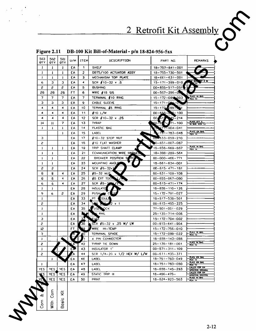
Figure 2.1 1 DB-100 Kit Bill-of-Material - p/n 18-824-956-Sxx
503 502 501 U/H IIEH [I[SCRIPTlON PART NO. REMARKS QTY Q1Y Q1Y
1 l l EA 1 SHELF 18 757 841-001
1 1 1 EA 2 0875/100 ACTUATOR ASSY 18-755-730-501
J 1 1 EA 3 MECHANSIM "fOP PLA1E 18 66 1 63 1 - 001
6 3 3 EA 4 SCR #10-32 " .5 15-17 1 -399-0 1 0 Y< iiOl. IJ1"( J IN tr[W 14
2 2 2 EA 5 BUSHING 00 855 517-051
28 29 2S FT 6 WIRE #18 SIS 00-557-286-003
7 7 7 EA 7 TERMINAL #10 RING 15 172 099 003 ....C( ... 86Gl lrtW 14
3 3 3 EA 9 CABLE SLEEVE 15 17 1 054 0 1 1
4 4 4 EA 10 "TERMINAL #6 RING 15-172-099-001
4 4 4 EA 11 #10 L/W 00-655-067 1 00
4 4 4 EA 12 SCR #10 32 y .25 00 615 245 214
14 11 7 EA 13 TYRAP 00 857 271 100 ....c< ON 5 ' ... 8o'C.. Rtw U
J 1 1 EA 1 4 PLASTIC BAG 1 5 171 004 Co4 1
1 EA 15 LABEL 1 8 751 783 048 OV.CC GH-nEW lA
3 EA 17 /110 32 STOP NUT 00 ('.33 059 2 10 2 EA 18 /110 FLAT WASHER 00 651 007 087
1 1 1 EA 19 TRIP SHAFT CLAI.CP 18-658-669-887 .....,. ........ flEW 1.&
1 1 EA 2 1 COW.IUNICATION WIRE 1-lARNESS 18 398 289 5&4 1 1 EA 22 BREAKER POSITION SWITCH 00 000 466 771
1 1 EA 23 MOUNTING ANGLE 18 661 634 001
2 2 EA 24 SCR #8 32x1 00 615 471 181
8 g 4 EA 25 f/8 32 NUT 00 631 109 108
a 8 4 EA 26 iB EXT TOOTH l/W 00-655-067-080
6 b 4 EA 27 SCR NB 32xl/2 00 615 o471 174
J J EA 28 INSULATOR 18 655 110 126
'9 6 2 EA 29 PUSH-IN CLEAT 15- 1 72 - 791 - 027
1 EA 33 PT MODULE 18 817 538 501
2 E A 34 SCR II 10-32 l( 1 00-615-435-225 J EA 35 FUSEBLOCK 77-901 -001-029
J EA 36 OIN RAIL 25-13-5-71o4-006
3 EA 37 FUSE 15 1 72 704 002
2 EA 38 SCR 1/8 32 lC .25 W/ LW 00 615 641 904
12 FT 39 WIRE HI TEI.CP 15 1 72 756 010
3 EA o40 "TERMINAL SPADE 15 172 099 022 lr[W 14 J EA 4 1 4 PIN CONNEC10R 18 655 143 058
2 EA 42 lYRAP liE DOWN 25-135-181-001 IVa IN 8'oC. rr(W 14
l EA 43 INSULATOR 1- 00-87 1 -311-109
2 EA 44 SCR 1 /4 20 " 1/2 HEX W/ L/W 00 6 1 1 435 371
J EA 46 LABEL 18-751 -783-049 PVC""·""' ft"(W 1.4
J EA 47 LABEL 18-75 1 -783-050 IVC:£ ON 8oll: II'[W 14
YES YES YES EA 48 LABEL 1 8 655 1 45 293 t.ti.UO FOil (iN CIRO(AIN; �
YES YE S YE S EA 49 STATIC TRIP Ill 18-486-475-t.ti.UO FOil (jN (PO( ..... �
YE S YE S YE S E A 50 PRINT 18 824 923 503 PloiCf N� lr[W 14
til i=-a.. f �
� 0 2 0 c ..c. -� L Ul 0 ....... 0 0 3: Q)
2-12
www . El
ectric
alPar
tMan
uals
. com
2 Retrofit Kit Assembly
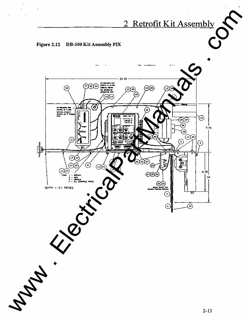
Figure 2.12 DB-100 Kit Assembly PIX
�--------------------------------24.16------------------------------�
DEPTH 5. 1 INCHES
7.75
2- 13 www . El
ectric
alPar
tMan
uals
. com
2 Retrofit Kit Assembly
Tools Required:
Installation Steps
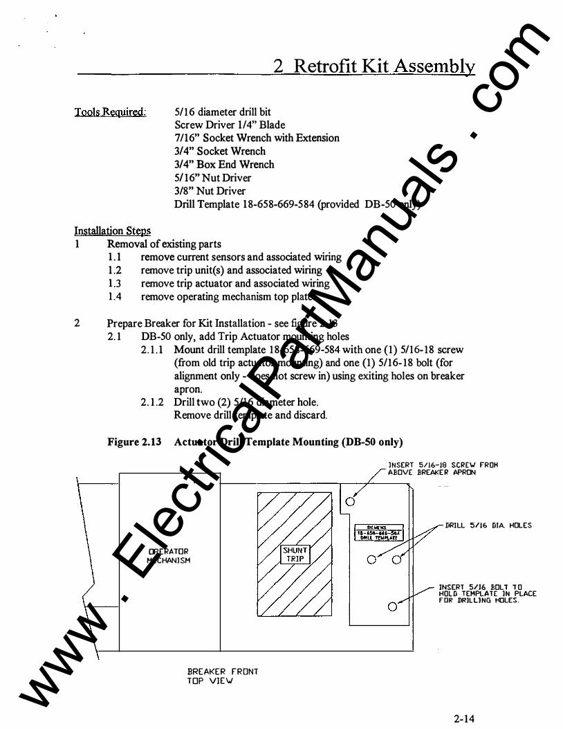
5/I6 diameter drill bit Screw Driver 114" Blade 7/16" Socket Wrench with Extension 3/4" Socket Wrench 3/4" Box End Wrench 5/16" Nut Driver 3/8" Nut Driver Drill Template 18-658-669-584 (provided DB-50 only)
I Removal of existing parts I.1 remove current sensors and associated wiring 1.2 remove trip unit(s) and associated wiring I.3 remove trip actuator and associated wiring I. 4 remove operating mechanism top plate.
2 Prepare Breaker for Kit Installation - see figure 2.13 2.I DB-50 only, add Trip Actuator mounting holes
2.1.I Mount drill template I8-658-669-584 with one (I) 5/I6-I8 screw (from old trip actuator mounting) and one (I) 5/I6-I8 bolt (for alignment only - does not screw in) using exiting holes on breaker apron.
2.I.2 Drill two (2) 5/16 diameter hole. Remove drill template and discard.
Figure 2.13 Actuator Drill Template Mounting (DB-50 only)
OPERATOR MECHANJSM
BREAKER FRONT TOP VIEV
l NSERT 5/16-19 SCRE\J FROH ABOVE BREAKE R APRON
DRILL 5/16 DIA. HOLES
INSERT 5/16 BOLT TO HOLD TEMPLATE lN PLACE fOR DRILLlNG HOLES:.
2-I4
www . El
ectric
alPar
tMan
uals
. com

2 Retrofit Kit Assembly
3 Mount New Devices 3 .1 Mount phase current sensors on the lower primary bus stabs. Mount such
that the HI face is towards the primary disconnect. 3.2 DB-75 and DB-100 only, install Trip Shaft Clamp - see figure 2.14.
The Trip Shaft Clamp must be located on the breaker trip shaft to line-up with the Trip Actuator Trip Bar.
Figure 2.14 Trip Shaft Clamp Mounting - DB-75 and DB-100 only
2-15 www . El
ectric
alPar
tMan
uals
. com

2 Retrofit Kit Assembly
3 .3 Mount Basic Trip Unit Kit on top of the operation mechanism in front of the arc chutes. WARNING - The breaker Main Contact Cross Bar must be moved towards the closed position to install the Trip Actuator. USE THE BREAKER SLOW CLOSE FEATURE TO MOVE THE BREAKER CROSS BAR AWAY FROM THE TRIP ACTUATOR The Basic Trip Unit Kit attaches to the breaker with screw into the top of the operating mechanism and 1/4-20 bolt(s) from the bottom side of the breaker into the actuator housing- see figure 2. 15.
3. 4 Return breaker to the open position.
Figure 2.15 Basic Trip Unit Kit Mounting (DB-25 Kit shown)
- FIELD WIRING -TERMINATE ON CURRENT SENSORS
AND SECONDARY DISCONN ECTS
TER M INATE ON PRI MARY D ISCONNECTS
1/4-20 BOLT(S) & WASHER(S) ------11------c=-
2- 16
www . El
ectric
alPar
tMan
uals
. com

2 Retrofit Kit Assembly
3.5 DB-25 and DB-50 only Install Bus Links and Bus Shims using 1/2" hardware. These parts and hardware are provided with each Basic Kit and are used to replace the three electro-mechanical trip unit coils - see figure 2.16.
Figure 2.16 Bus Link and Bus Shim Installation (DB-25 Shown)
2-17 www . El
ectric
alPar
tMan
uals
. com

2 Retrofit Kit Assembly
4 Adjust Trip Actuator 4. 1 DB-25 and DB-50 Kits - see figure 2. 17
4 . 1. 1 Adjust nuts on actuator shaft so that ann is in contact with lever and lever is just starting to rotate
4. 1.2 Adjust rubber bumper and nut on end of trip actuator shaft so that when breaker is open, breaker cross bar is in contact with trip actuator shaft and trip actuator is reset.
Figure 2.17 DB-25 and DB-50 Trip Actuator
Breaker Cross Bar
Breaker Trip Bar Lever
2- 18
www . El
ectric
alPar
tMan
uals
. com

2 Retrofit Kit Assembly
4.2 DB-75 and DB-100 Kits- see figure 2.18
4.2. 1 Adjust nuts on actuator shaft so that trip arm is in not in contact with the breaker trip shaft clamp but such that the trip arm will operate the trip shaft clamp to trip the breaker.
4.2.2 Adjust rubber bumper and nut on end of trip actuator shaft so that when breaker is open, breaker cross bar is in contact with trip actuator shaft and trip actuator is reset.
Figure 2.18 DB-75 and DB-100 Trip Actuator
Breaker Cross Bar
Trip Shaft Clomp
0 Trip Arm
Trip Shaft
2-19 www . El
ectric
alPar
tMan
uals
. com

2 Retrofit Kit Assembly
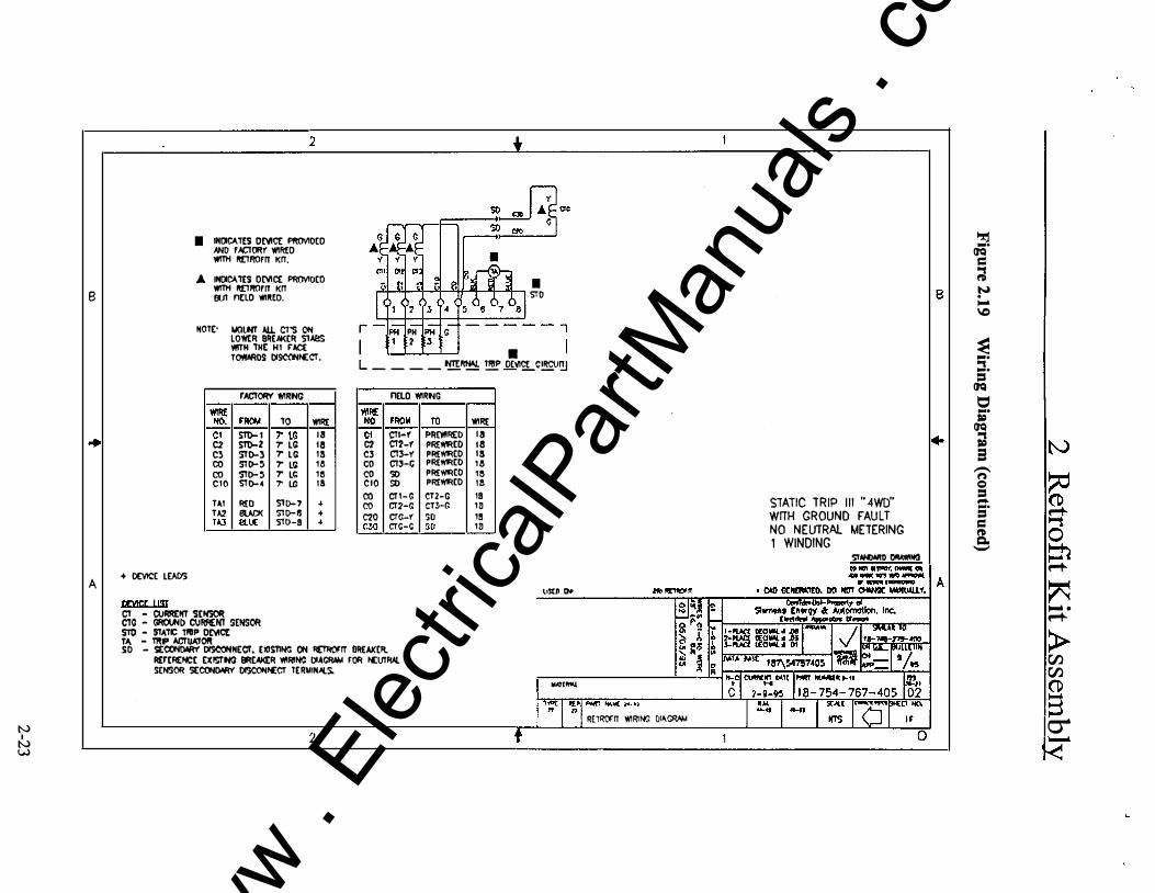
5 Complete Field Wiring - see figure 2.19 (three (3) sheets) 5.1 Reference the Bill-of-Material for required wiring diagram 5.2 Complete the "Field Wiring" using prewired conductors on kits (one end
loose) and Sensor Ground Wiring Kit. • connect to breaker mounted sensors • connect to primary bus (tfPT module is present)
Connect to source (line side) ofbreaker primary disconnect. Spade lugs connect under head of primary disconnect mounting bolts.
• connect to secondary disconnect (if neutral sensor required). Reference existing breaker wiring diagram for neutral sensor secondary disconnect terminals.
Bundle wires and retain with tyraps. Route wire to avoid moving parts, sharp edges, and primary conductors.
2-20 www . El
ectric
alPar
tMan
uals
. com

2 1
• INOICI.TES ONCE I'F!(MOCO � r.ICI'ORY WIR£0 � .... Vl'llH RLIROI'lT Kn (JQ
= A INOICI.TES ONCE PF10>10CO
Vl'llH RLIROI'lT Kn • 8 atJT ri[LO 'I'IIR£0 S'TO B
., � � """' \C
NOl£: NOVNT All Cl"S ON LOI¥£R eREAK£R STABS PH PH • Vl'llH TH[ HI rAe£
? 3 TOWAAI>S DISCONNECT. • � .... L ____ tm:R"!!:_ T� O['f'I!!_SIRCttn j
�'M'IH ort II'ITHM GAO. EL£11ENT
., .... =
(JQ r ACTOR'! WIRING Fl[l() WIRING t::l ...
I'IIR£ WI\{ NO. F'ROII TO WIR[ NO. rROM TO WFI£ Cl STD-1 7' lC 18 C1 Cli-Y PREI'I!R£0 18 t:1 STD-2 7' lC 18 t:1 Cl2'-Y Pf<EW'RED HI CJ S'TD-J 7' lC 1!1 CJ CTJ-Y PR(WIR(D 18 co STD-4 7' lC 1a co CTJ-G PREW!RED 18
T,l,l REO ST0-7 .. co CT1-G C12-G 19 STATIC TRIP Ill "3Yf' OR �3WG" TA2 BLACK ST0-6 .. co CT2-G CT3-G 18 NO GROUND FAULT OR WITH GROUND FAULT T,I,J 6LVE ST0-3 ..
NO NEUTRAL METERING I WINDING
� (JQ � IN a
� � 0
!il'.w:l'RO� + OE\4CE LU.OS
=:n f""'+-
A A 1•Jt� oro !l£\lC£ l!!IT CT - CIJRAEHT '.iE� STO - STATIC TRIP O£VIC[ TA - 1RIP ACI'\IAT� " 'lO - 'JCCOIIDAAV OISCOIINCCT, £1(1\iliNil ON R£TROrn BR£m:R. I .. I'IErEI'IENCt [ 1(1$TINC: IJR[AI(f:ft WlftNC DIACit'M rOit N[\Jllt'.l I ., SENSM �COI«JAA'Y Ol!leONNECT TERNINAI.S. ..
li:
� """" . f""'+-
> (/) (/)
� (l)
N N
RETROm Kn WIRING 01�11
2 1 s r::r �
.......
www . El
ectric
alPar
tMan
uals
. com

N I N N
B
A
2
• INOit:Al[S ()[VIC£ PROVIOCD 00 r ACTO!tf 'IIIREO
r-�' 91�A.cc:n. so y 0011
WITH RE"TROFT! I( IT. A INOit:Al[S D£VIC£ PROVIOCD WITH RE"lmlf11 KIT 111.11 FIElb '/IIF!£0.
NOlt. NOUNT All CT'S ON LOWER ero.KER STABS WITH THE H1 r-'.a: TOWARO<:: C:CSCCINI£CT.
PH lPH lC 2 13 •
• S'TD
L - - - -NTE:R� lRIP �C!_CfRClffJ
FACTMY WI'<IN<l
+ O£VICE LUOS
Q[)'!C£ LIST
CT - CURRENT S£NSM CTN - NEUTRAl CURRE:Nl SENSOR S'TO - STATIC TRIP DEVICE 1A - TRP -'.CTU-'.TOR
WIRE NO
Cl C2 CJ co co C10
TA1 TA2 1},.3
SO - SECONDARY C:CSCONI£CT, El(lS'TING ON RE1ROF'JT BREH<ER.
rFO.A
ST0-1 STD-2 "JT0-.3 ST0-.1 ST0-.1 'iT0-5
R£0 BlACK eux
Rt:r[Rf:NCE [l(lS'TING DR[AI((ft WIRING O�lol FOR 101RAI. SENSOFI S{C('HW!Y DISCONNECT l[FMNAI.S.
10
7• LG 7• LG ,. LG 1· LG 7• LG 7· LG
S'T0-7 S'TU-� Sl0-3
riELD 'IIIRING 'IIIR£
WIRE NO. rR(ll,4 TO
16 Cl CTI-Y PREWIREO 16 C2 CT2-Y PREWIR(D 18 CJ CT.3-Y PREll'< EO 18 co CT!>-G PREWIRED 18 co so PR[WJ<(D 18 CIO 50 PR£"1111'1(0
co CT1-G CTZ-G -+ co CT2-G CT!>-G � -+ C20 CTN-Y SD
C:Y.I CTN-G 50
\l!t� l)f
�.(1[".\1.
"IIIRE
18 13 18 IS IS IS
18 18
18 I S
R[lROFIT WIRING OI.I!GRM4 2
STATIC TRIP Ill ft 4WR• WITH GROUND FAULl NO NEUTRAL METERING t WINDING
S!NtW11> biW'II4C IIDtenannoc....r"'
B
..,.(W"':'.:'� I A • CJO co.tRAT£0. CO NOT Clf.IH:£ WN.LII.l Y.
0
� ... (JQ = ., � N � \:>
� ... :::!. =
(JQ t:1 ... �
(JQ ., � e -n Q = .... ... = = � -
IN
� � 0 ::n �
� ,..... . �
> rJ) rJ) (1)
§. �
www . El
ectric
alPar
tMan
uals
. com
N I N w
8
A + DEVICE LD.O'>
oom;r liST
2
I IHOICA'TES ONict PftOVIOCO ANO f N::TORY WIR£0 WITH I'I[TR()f!T KIT.
.A INC.CA'TES OC't'IC£ PROVIDED WITH I'I[TROfiT KIT lli.Jl nno Wlll£0.
HOT£· t.IOI.M All CT'S ON LowtR 8RE.IKER STAaS ¥11TH 'TH£ HI f'la. T<WINIOS DISCONNECT.
r ACTORY WIRNG
WIRE �. f'ROI.I 'TO WIRE Cl ST0- 1 7' LG 18 C2 ST0-2 T LG 18 Cl STD-3 T LG 1!1 co STD-5 T LC HI
co STD-5 T LG 1!j CIO STD-4 7' l.G 18 T._l R£0 STD-7 + T/,2 ew.:K STD-15 + T.l.J Ill� STD-9 +
C1 - CIJIIREIIT SENSOR ClC - �I> CIJ!ft:NT SENSOR STO - 9TA'TIC TI'IIP Ot't1ct T>\ - mP ACTUJ\IOft
� S?��tl� so, � GJ
� u1 � � �� � � � I I • I STO
PH jPH J G 2 13
• L _ _ _ _ �� � OC't'I£LC!.f!£J'!J
nELO W!RtlG ¥fiRE NO fRO II TO WIRE Ct CTI-f PF!C'If!R£0 1 3 C? CT1-f PRI:W!RED 18 C3 CT3-Y PR£WREO 1 3 co CT3-C PR£WRED 1& co so PR£WIREO 1!j CIO so PREWREO I a co CT I- G CT2-C 19 co CT2-G CT3-G 18 C20 CTG-Y so 19 ('.:1() CTC-C so 18
li$[� Do
SO - !;EeoNboti!Y O!SeONN£Cf. E l(!snN<: ON RETROf'IT I!REAICCil M:rERENCE £lCISTI\IG 9REAI<£R ¥1!RIN<l OIAGR.IM fOR NEUTRAl SENSOR SEeoNON!l' OI"..CONNECT TER141H-*I.S.
""'I""'-
2
� -·
(JQ = ., �
B l � '""' \D
� -· ., -· =
(JQ � -· =
(JQ ;1 IN a
-f) � Q
STATIC TRIP I l l " 4WD" = --·
WITH GROUND FAULT = � NO NEUTRAL METERING
= """t � 0 1 WINDING c. - � SI.INDNIO �NG
� A � � ·
�
> r.n r.n CD s cr' R£1�1T WIRING 01��
�
www . El
ectric
alPar
tMan
uals
. com
2 Retrofit Kit Assembly
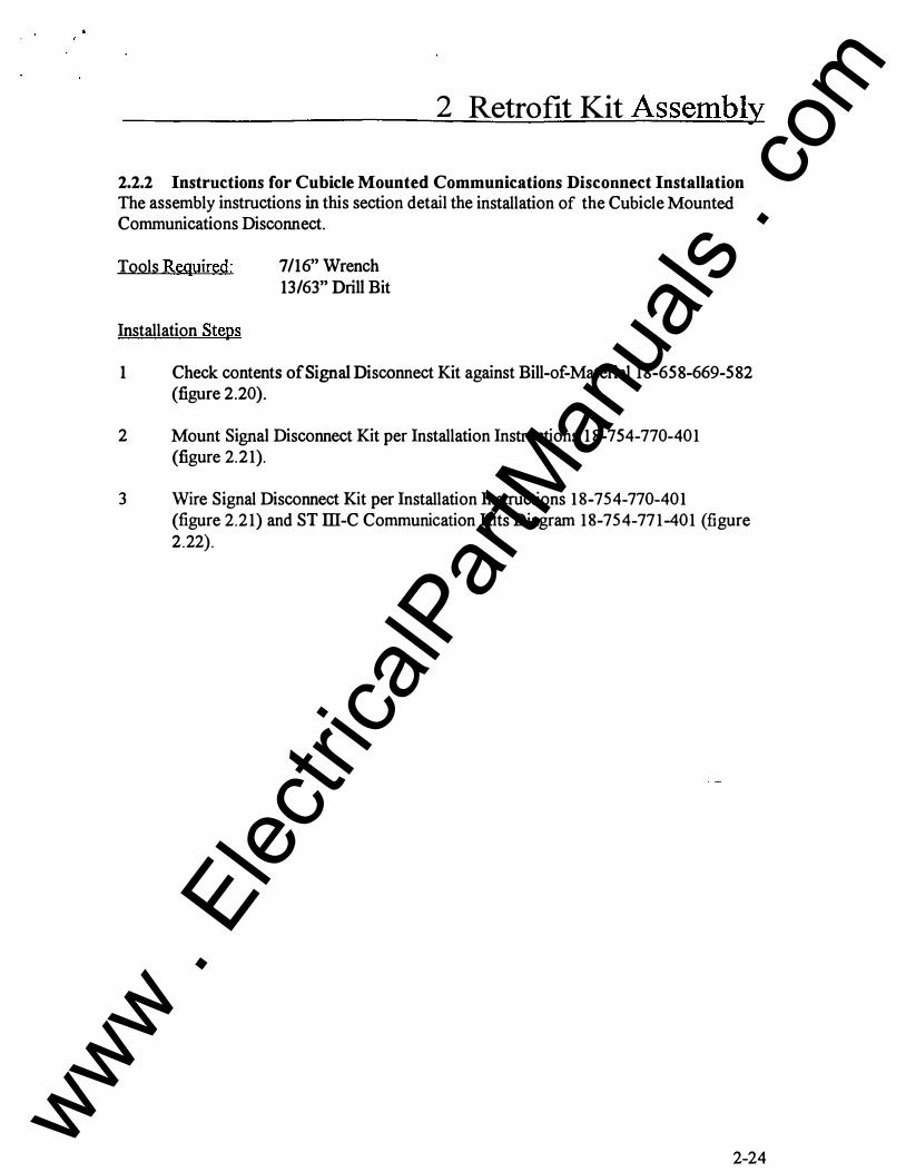
2.2.2 Instructions for Cubicle Mounted Communications Disconnect Installation The assembly instructions in this section detail the installation of the Cubicle Mounted Communications Disconnect.
Tools Required:
Installation Steps
7/16" Wrench 13/63" Drill Bit
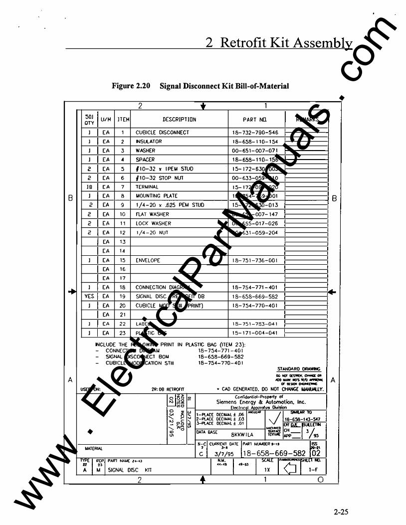
1 Check contents of Signal Disconnect Kit against Bill-of-Material 18-658-669-582 (figure 2.20).
2 Mount Signal Disconnect Kit per Installation Instructions 18-754-770-401 (figure 2.21).
3 Wire Signal Disconnect Kit per Installation Instructions 18-7 54-770-401 (figure 2.21) and ST ill-C Communication Kits Diagram 18-754-771-401 (figure 2.22) .
2-24
www . El
ectric
alPar
tMan
uals
. com
8
+
A
2 Retrofit Kit Assembly
Figure 2.20 Signal Disconnect Kit Bill-of-Material
2 i' 1 501
U/M H EM DESCRIPT ION PART NO. REMARKS OTY
J EA 1 CUBICLE DISCONNECT 1 8- 732-790-546
l EA 2 INSULATOR 1 8- 658- 1 1 0- 1 54
J EA 3 WASHER 00-651-007-07 1
J EA 4 SPACER 1 8-658- 1 1 0- 156 z EA 5 # 1 0-32 Y I PEIA STUD 1 5- 1 72- 630- 003
2 EA 6 / 1 0-32 SlOP NUT 00-633-059-2 1 0
J S E A 7 T[Rf.I1NAL 1 5- 1 72-099- 020
J EA 8 IAOUNTING PLATE 1 8- 754-769-001
2 EA 9 1 /4-20 x .625 PEM STUD 1 5- 1 72-630-0 1 3
z EA 10 fLAT WASHER 00- 65 1 -007- 147
2 E A 1 1 LOCK WASHER 00-655-01 7-026
2 EA 1 2 1 /4 - 20 NUT 00- 63 1 -059-204
EA 13
EA 1 4
J EA 15 EliNE LOPE 1 8- 75 1 -736-00 1
EA 1 6
EA 1 7
J EA 18 CONNECTION DIAGRAM 1 8-754-771 - 401
YES EA 1 9 SIGNAL DISC RETROFIT 08 1 8-658-669-582
J EA 20 CUBICLE MOD STill (PRINT) I 8-754-770-40 I EA 2 1
J EA 22 LABEL 1 8- 75 1 -783-04 1
J EA 23 PLASTIC BAG 1 5- 1 7 1 -004-041
NCLUDE THE FOLLOWING PRINT IN PLASTIC BAG (ITEM 23): --
-
liSEO ON:
I.IATERIAL
CONNECTION DIAGRA.I.I SIGNAL DISCONNECT BOf.l
CUBICLE MODIFICATION STill
2R: DB RETROfiT
��� l/'iO
13 11 ....... ,...
s i-(.) .... ooJ
� e 5 � ....... ,.,,., (.J ID 0 lJl
TYPE
I R(Pt P.A.Rl NAI.t( l<-43
!I 2� A M SIGNAL DISC KIT
2
18-754-77 1 -40 1 18-658-669- 582
18-754-770 - 4 0 I STAN�RO ORA.WIIC
Oli iCIT IIE'51IICII'. OWU: C)II .100 IWII( IICI'S W/0 -
� -- � • CAD GENERATED. DO NOT CHANGE NAN�Y.
{.(onf&denlioi-Prcperty of Siemens Energy & Automation. Inc.
[1(0(.\ncol AOoorol11s Division 1-PLACE OECIUAL ! .06 NIGWR J 2-PLACE DECIMAL ! .Ct3 3-PLACE OECII.IAL ! .01
loloiO-IIIt:O DATA BASE
8KKW I LA SltRI'j(( 1[Y1UI[
SIUUR TO 16-656-143-SC7 OR�r��L[TW Oi 3/ APP_ 95
N-C, ctJRR(N'T DATE rAin NW8ER .,_,, Fo� 2 ., �
c 3/7/95 1 8- 658- 669 - 582 02
+ U-41 48-$3 I N,U. I I SCALE r-oro �-
I X 1 -F
1 0
8
.. ....-
A
2-25 www . El
ectric
alPar
tMan
uals
. com

2
' v; -- · ·�o ij'
8
• s ' ©I I I I I ! 10 It 12 13
A
N t!.> 2 0'1
INSTALLATION INSTRUCTIONS FOR KIT # 1 8-658-669-582. NOTES: 1 ) FOR MOUNTING COMMUNITIONS DISCONNECT ASSEMBLY,
LOCATE TWO (2) SQUARE HOLES IN CUBICLE LEFT FRONT FORMED CHANNEL OR DR ILL TWO (2) 1 3/64 HOLES AS REQU IRED IF SQUARE HOLES ARE NOT PRESENT.
INSERT .25 x .625 PEM STUDS FROM INSIDE FORMED CHANNEL, THROUGH COMMUNICATIONS DISCONN ECT MOUNTING PLAT[, THROUGH FORMED CHANNEL, AND INSTALL WASHERS AN D NUT HARDWARE .
2) TERMINAL DESIGNATIONS: 1. NO CONNECT ION 2. 1 5VDC+ 3. 1 5VDC RETURN 4. RS 485 DATA + 5. RS 485 DATA -6. NO CON NECTION 7. NO CON NECTION 8. OPEN/ALARM OUTPUT (- ) 9. CLOSE OUTPUT (- )
1 0. CLOSE/OPE N SOURCE ( + ) 1 1 . PT SECONDARY PHASE 1 1 2 . PT SECONDARY PHASE 2 1 3. PT SECONDARY PHASE 3 1 4. PT SECONDARY NEUTRAL � ��
OO IIIJII .,....,. C:....: �
8
1 5. NO CONNECTION t•S::Crt 00. 1&-�f'M·� .. _-;: �::"' I A • 00 !lE"CI'WtO. 00 NIJI CHI.It'J! �W.III.l.1. <fO ot �
¥mlfll.
� -· (JQ = � N � """'
CZl -·
� =a; -� -· � () 0 = = � � �
I N - · ......
;' � � .... !. ('1) ;-� ....
-· 0 0 = � � � f""t-.... 2 � () ....
� · - ·
f""t-0 = � > (/) (/)
('1)
g. �
www . El
ectric
alPar
tMan
uals
. com

N I N .....;)
8
A
2
S T AT I C TRI P I I J - C COMMUNICAT I O N S KI T S
llC f1lllt:R �1.1f'f1.1 KIT
J�J.?W� :'101�
, , I I
TO Pltli!Mf l rJN61:Rl CII� IIOCOPIIIG I'!N[R D11 l ��r<t�R �
7
��-�!l.Y �TRITI�� - - U _j 2
IJ!:CP Do
WA1E""-l
DC PROYIER !:UF'Pl Y KIH ltJS-658-1 43-'549 FEEOJNG HAl( TW UNITS• ltJ9-659-H3-'550 FEEDING MMC EIGHT LINJTS• ltJS-659- 1 '.3-551 rEEDING MAl( �JXTEEN UNI T � · w l:TIIJ AND BDIJ, EACH COli•ITS: D r-£ UNlT
KIT S INCLUIIE l{]ltnJNG BRACKTE S & HARII'tiARE. NO rUSES
2 CUBICAL MOUNTED SIGNAL DJSCDNr£CT Kll ltJS-659-669-592, OOB NOT INCLUDE BREAKER MATING DJ s;GDNf'£CT.
3 BREAKER POSlTION S'w'ITCH l!00-000-466-77J <REPLACEMENT COMPONENT, r£1 HARil'WARE INCLUDED>
4 BREAKER MOltiTED COMMUNICAllCNS VlRE HARNESS
ltJS-398-289-564. <REPLACEMENT COMPONENT. NO HARII'tiARE INCLUilED>
5 PT MODULE 4 PIN CONNECTOR tiS-658-143-058, <REPLACEMENT CDf'lPONENl, NO HARDY/ARE lNCLUDE DJ.
6 RL PT-MODI.ILE 1!18-817-539-501. <REPLACEMENT COMPONENTS. NO HARD'WARE INCLUIIEil>.
7 CAUTION! SEE Kll INSTRUCTIONS FER NEUTRAL CONNECTION.
9 DATA lo'IRE S L E AVJNG Tt-l: GEAR. I.E. TO HOST COMPUTER. REQUIRED T RANSIENT ELIMINATOR. CONSULT FACTORY FOR DE T AIL S. REf ERENCE m-172-664-051 OR -052.
SIAit[)IRO llAA11!!!(l
8
lito
CIO _. .,..,. OWIW .. . - � .... .,. ,.,....... • 001 «t£1tl.T[0. co lltll' = =Lf. I A
g
� .. il J. ... .. a I I
0
� (JQ c � � � �
00 � � n n e a a c = -· e. IN -· =
� =
� � a � a ... =
=n (JQ � M-a
� � · M-
> en en ('D
§. �
www . El
ectric
alPar
tMan
uals
. com

2 Retrofit Kit Assembly
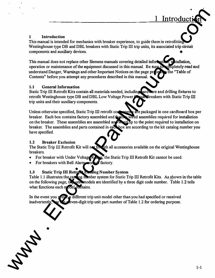
2.2.3 Instructions for Breaker Display Unit Installation The assembly instructions in this section detail the installation of the Breaker Display Unit (BDU).
The BDU is mounted on the cubicle door and is plugged via a cable connector into the Static Trip ill.
Kit contains materials and instructions necessary to mount Breaker Display Unit (BDU) on a breaker cubicle door. Extemal 15 VDC power supply is required. See Instruction Bulletin SG-3118-0 1 included in Trip Unit box for operating instructions.
Tools Required:
Installation Steps
Drill .187 diameter Drill .750 diameter Deburring Tool 1/4" Hex Socket or Nut Driver
1 Check contents ofBDU kit against Bill-of-Material (see figure 2.23) for completeness.
2 Locate BDU on cubicle door as required to avoid interference with cubicle internal parts and to allow wire routing.
Drill holes per figure 2.23 using template 18-658-143-574, remove all burrs.
3 Mount BDU on cubicle door using three (3) #6-32 screws from kit. Insert screws from inside cubicle door.
4 Plug cord set into BDU, route wires from BDU to breaker, tie cord set in position with ty-raps. Route wire to:
· -
• avoid sharp edges, pinch points, and moving parts, • allow opening and closing of cubicle door, and • allow for breaker travel.
5 Double check wire route and plug connector into Static Trip device. See Instruction Bulletin SG-3118-0 1 for operating instructions.
CAUTION BDU cable must be connected and disconnected to breaker to allow removing breaker from cubicle.
2-28
www . El
ectric
alPar
tMan
uals
. com

Figure 2.23 BDU Kit Bill-of-Material
B
+
A
2 573
U/H l TEM DESCRJPTIDN QTY
J EA I INSTRUCTION - PRINT
J EA 2 BREAKER DISPLAY UNIT
J EA 3 CORD SET 3 EA 4 SCREW. #6 lC .38 LG.
tO EA 5 TYRAP MOUNTING PLATE
20 EA 6 TYRAP J EA 7 DRILL TEMPLATE
J EA B PLASTIC BAG
J EA 9 LABEL
USED ON: 2R: R[TROrn KnS 8 f-'" ' (.1 ' \l) (.J
I.IATERIAI.
TYPE
I REP 1 PART NAL4( i!'-u
2:1 2l A M BREAKER DISPLAY UNIT
2
2 Retrofit Kit Assembly
t 1 PART NO. REMARKS
1 8-754-766- 40 1
1 8-658-582-544
1 8-658-582- 546
1 5- 1 7 1 -074 - 0 1 0
1 5- 1 7 1 -949- 093
00-857-2 7 1 - 230
1 8- 658- 1 43- 574
1 5- 1 7 1 -004 -04 1
1 8-75 1 -783-037
� -
STANDARD DRAWING
00 NOT IXSTAOV. OW« OR - loWII< NO"S W/0 -
u OOilllH [NiliNE� • CAO GENERATED. 00 NOT C"HANGE MANUALLY.
((;nfo�nlioi-Pr�y of Siemens Energy & Automation, Inc.
£1eetrlcol .i.PI)Orolus Division 1-PI).C[ OECtLIAl :1:: .06 �I.AR J Slt.III.).R 10
2-PI.AC£ OECII.IAL :1:: .OJ J-P\ACE OECIUAL :1: .01
�0 04.TA BAS£ 8KKW I L7
SliRr.OCf T(rltoR[
18-(158-701-573 OR OJE : rlLETIN CH _ 2� APP 95 N-CI ctJRRENT DAlE YART NUI.ISER 9-19 IJISS N 21;i9s 1 8- 558 - 669 -579 02l
�+ ��-4 CG-53 I N.t.l.
I I :r j<J[�rNo.
1 0
8
�
A
2-29 www . El
ectric
alPar
tMan
uals
. com

'
2 Retrofit Kit Assembly
Figure 2.24 BDU Kit Installation Instructions
HOLE PATIERN fOR t.IOUNTING BREAKER DISPLAY UNIT. {B.O.U.)
LOCATE AS REQUIRED IN CUBICLE 00011 TO AVOID INTERNAL PARTS AND TO ALLOW RACKING Of BREAKER.
� _/ � B . D . U .
1 .56
3.80
1 .38
Plugs into Trip Unit ST I l l L .H. recepticle ot front.
2-30
www . El
ectric
alPar
tMan
uals
. com

3 Breaker Testing and Breaker Labeling
3 Breaker Testing and Breaker Labeling
3.1 General Test Description The test procedures descnoed in this section apply to Static Trip ill Retrofit Kits for Westinghouse type DB and DBL circuit breakers.
Test recommendations descnoed in this section focus on electrical clearance testing of the new components involved and the assurance that the newly installed breaker trip circuit is functioning properly. The test procedures descnoed do not cover and breaker performance testing; breaker performance testing, means to test whether or not a breaker is still capable of meeting its interruption rating as expressed on its rating plate. It is the respo11Sloility of the retrofitter to inspect, test and perform and necessazy work to confirm the electrical and mechanical integrity of the breaker. The retrofit Kit components when properly installed per our procedures have no impact on breaker perfonnance. Breaker . performance is simply a function of the overall breaker condition.
3.2 Testing Completely read and understand the Danger, Warning and Safety Instructions on page i of this manual before attempting operation, maintenance or modification of the equipment discussed in this manual.
Hozordoua Volt� w;,t c.ou&e -• inj"'Y or death.
P.o.sonnel cond!K.t� lh:s l...t proc4106ure ,_j be (rolned in the use of 41ectrlcol IO!St OQUipmen( ·� "'Otoge& 9".0161' 1hOn (iO() "''ils. Pei'$OM6I mu!ll underdond ond be t'omiliot �h cofdy precoo,AloN; ond proc.dur" 0� to tueh led..
3.3 Low Frequency Withstand Test Low Frequency Withstand Test is in accordance with ANSI C37.59-1991 (Requirements for Conversion ofPower Switchgear Equipment) and C37.50-1989 (Low-Voltage AC Power Circuit Breakers Used in Enclosures - Test Procedures).
1 . Apply ground potential to all secondary disconnects and also ground all trip unit terminals at the top of the Static Trip ill device.
3-1
' ..
www . El
ectric
alPar
tMan
uals
. com

. ,.
3 Breaker Testing and Breaker Labeli�
2. Jumper upper primary disconnects, jumper lower disconnects and apply 1320 VAC for one (1) minute between the jumpered primary disconnects with the breaker in the open position. Some more sensitive highpots may buzz or trip due to magnetizing current of the PT module, if installed. In such case the PT module fuses may be removed for this test.
Breaker must pass Low Frequency Withstand Test, otherwise, determine cause of failure, correct the problem and retest.
3. Jumper all six primary disconnects. Leave all other ground jumpers in place and apply 1320 VAC for one (1} minute betweenjumpered primary disconnects and ground.
Breaker must pass Low Frequency Withstand Test, otherwise, determine cause of failure, correct the problem and retest.
4. Jumper top and bottom primary disconnects of Phase B and Phase C (four ( 4) terminals jumpered) and connect to ground. Jumper upper to lower primary disconnect of Phase A and apply 1320 V AC for one (1) minute between Phase A and ground.
Breaker must pass Low Frequency Withstand Test, otherwise, determine cause of failure, correct the problem and retest.
5. Repeat step 4 for voltage applied to Phase B, jumper Phase A to Phase C.
6. Repeat step 4 for voltage applied to Phase C, jumper Phase A to Phase B.
7. Repeat steps 4, 5 and 6 with the breaker closed.
Breaker must pass Low Frequency Withstand Test, otherwise, determine cause of failure, correct the problem and retest.
8. Remove all previous jumpers with the exception of the jumpers on the communication disconnects and trip unit termihals. The jumpers should still be connected to ground. Jumper all six ( 6) primary disconnects and connect to ground. Jumper all secondary disconnects and apply 600 V AC for one minute between the secondary disconnect and ground. The breaker may be open or closed for this test. This test will assure that the motor (on electrically operated breakers only) is in good operating condition.
.Breaker must pass Low Frequency Withstand Test, otherwise, determine cause of failure, correct the problem and retest.
9. Disconnect the motor leads and repeat step 6, except using 900 V AC instead of 600 V AC for one minute. www .
Elec
tricalP
artM
anua
ls . c
om

'�eaker Testing and Breaker Labeling
... •requency Withstand Test, otherwise, detennine cause of /olem and retest.
.Nious jumpers . .s follows:
.. six ( 6) primaries to ground all communication disconnects to ground
' all secondary disconnects to ground • disconnect the "ground" wire on Static Trip m C versions • jumper tenninal one (I) through eight (8) on the trip unit tenninal block
Apply 300 VAC for one minute between trip unit jumper and ground.
Breaker must pass Low Frequency Withstand Test, otherwise, detennine cause of failure, correct the problem and retest.
3.4 Trip Unit Testing Testing of the trip unit is descn"bed in Static Trip m trip unit Bulletin SG3 1 18-01, pages 29-3 5. The bulletin is enclosed.
3.5 Labeling ANSI/IEEE C3 7 .59-199 1(Requirements for Conversion of Power Switchgear Equipment) requires a nameplate with the converter (retrofitter) name, address, identification number, date, and rating information. The Retrofit Basic Trip Kit incudes a partially completed nameplate desribing the Siemens Retrofit Kit. The converter (retrofitter) must complete the remaining information (see figure 3 . 1).
Figure 3 . 1 Converted B y Label
SIEMENS Typei=:--;;::::::===::::!.'.:.:Se:..:..:ri.:.:.oi....:.No:..:,. �-.I ___ ___,.JI Trip W/0 11---------1 Comm W/OI'-----=---.:-:--,...--.._..._--1 s�nsor Ratings: Top USG<I I Ufg.Oote E3 Grd. Sensor!! (when u!led) I lnst.Book Siemens Energy & Automation. Inc. Roleiqh. NC �.Coda in USA
�=ed By 11-------------11 10 No. �- =========•1 -;-U;;-:fg:-;.Oo;-:-t:-:-e-:1 =====:!.
3-3 www . El
ectric
alPar
tMan
uals
. com

SIEMENS
Static Trip Ill Retrofit for Westinghouse Type DB Low Voltage Power Circuit Breakers
Installation Instructions
www . El
ectric
alPar
tMan
uals
. com

Hazardous voltages ore prese nt in the equipment which will couee severe personal injury and equipment d<:Jrno�e. Always de-energize <:Jnd remove the bre<:Jker from •ts cubicle �fore mointenonce or ret rofit work. Maintenance or ret rofit should be performed only by qualified personnel . The use of unauthorized ports in the rePQir of the equipment or tampering by unquollflecl person nel will result In dangerous conditione which con couse severe personal injury or e<:�uipment dornage. Follow oil s<:Jfety i nstructions <::ontoi ned herein .
WARNING The Power Circ uit Breakers discussed in the manual may contoin o epring chorged mecha nism that con couee severe injury. Befo re working on any breaker assure that the spin9 s o re disch<:Jrged ond the contacts ore in the open position. Some procedures moy require the breaker to be c losed. In such coses. assure thot the contacts ore securely wedged to prevent on inadvertent open ing o( t he breoker. Remove wedge. open <:J nd discharge the breaker os soon <:IS the procedure is compl<�ted th<:Jt required {he breoker to be closed.
IMPORTANT The i nformation contained he.rein is genera l in natura and does not rolieve t he user of the responsibility to use sound pradices in o pplicotion , installation. operation. m<:Jintenonce and retrofit of the eq uipment purchased. Siemens reservos the right lo make ch<:Jnges in the specifications shewn h�reln or to moke improvements ot ony time wit hout notice or obligations. Should <:1 conf lict <:�rise between t he g e neral information c o ntained in this publication and the co nte nts of d rawings or supplemont<:Jry m<:Jteri<:JI, the Iotter sholl t<:Jke precedence.
NOTE For the purpose of this monuol a qualified person Is one who is fornilior with t.he inGtollotion� c;onGtn .. u;:t.ion. 015160mb1y ond opcsrotion of the eq uipment ond the hozords Involved. In odd111on, he hos the following quoliflcations: (o} is £ruined ond outhorized to de-energize. clear, 9round, and tog
circuits and eQuipme.nt in accordance with estobhshed safely pr<:Jctices.
(b) 1$ trolned In thE> proper core ond use of protective e<:�ulpment such os rubber gloves. hard hots. safety glosses or face shields. f losh clothing , etc. , in accordance with established sofety practices.
(c) is trained to perform maintenance ond assembly work on low voltage power circuit breakers.
(d) Is trained ln rendering first old.
SUMMARY These instructions do not purport to cover oil detoils or variations in equipment, nor to provide for evory poss i bl � contingency to be met in connection with instollotion, operation , or mai ntenance. Should further information be dosired or shou ld P<lrliculor problems orise which ore not covered sufficiently for the purc haser's purposes, the m<:Jtter should be referred to the loc<:JI so les office, listed on bock of thls instruction 9 uide.
The contents of this instruction rnonuol should not become port of or modify any prior or existln9 09reement, commit me nt . or relationship. The soles contract contains the entire obligation of Siemens Energy & Automation. Inc. Any statements conta ined h erein do not create new warranties or modify t he e)(isting worronty.
..
www . El
ectric
alPar
tMan
uals
. com

Table of Contents
1 Introduction . . . . . . . . . . . . . . . . . . . . . . . . . . . . . . . . . . . . . . . . . . . . . . . . . . . . . . . . . . . . . . . . . . . . . . . . . . . . . . . . . . . . . . 1-1 1 . 1 General lnfonnation . . . . . . . . . . . . . . . . . . . . . . . . . . . . . . . . . . . . . . . . . . . . . . . . . . . . . . . . . . . . . . . . 1-1 1 .2 Breaker Exclusion . . . . . . . . . . . . . . . . . . . . . . . . . . . . . . . . . . . . . . . . . . . . . . . . . . . . . . . . . . . . . . . . . . . 1-1 1 .3 Static Trip ill Retrofit Catalog Number System . . . . . . . . . . . . . . . . . . . . . . 1-1 1 .4 Static Trip ill Retrofit Kit - contents . . . . . . . . . . . . . . . . . . . . . . . . . . . . . . . . . . . . . . 1-4 1 .5 Kit Identification . . . . . . . . . . . . . . . . . . . . . . . . . . . . . . . . . . . . . . . . . . . . . . . . . . . . . . . . . . . . . . . . . . . . . 1 -4
2 Retrofit Kit Assembly . . . . . . . . . . . . . . . . . . . . . . . . . . . . . . . . . . . . . . .. . . .. . . . . . . . .. . . . . . . . . . . . . . . . . . . 2-1 2. 1 Danger and Warning lnfonnation . . . . . . . . . . . . . . . . . . . . . . . . . . . . . . . . . . . . . . . . . . . . . 2-1 2.2 Assembly Instructions . . . . . . . . . .. . . . . . . . . . . . . . . . . . . . . . . . . . . . . . . . . . . . . . . . . . . . . . . . . . . . 2-1
2.2. 1 Instructions for Sensors and Basic Trip Unit Kit . . . . . . . . . . . 2-1 Installation
2.2.2 Instructions for Cubicle Mount� . . . . . . . . . . . . . .. . . . . . . . . . . . .. . . . . . 2-24 Communications Disconnect Installation
2.2.3 Instructions for Breaker Display Unit Installation . . . . . . . . . 2-28
3 Breaker Testing and Breaker Labeling . . . . . . . . . . . . . . . . . . . . . . . . . . . . . . . . . . . . . . . . . . . . 3-1 3 . 1 General Test Description . . . . . . . . . . . . . . . . . . . . . . . . . . . . . . . . . . . . . . . . . . . . . . . . . . . . . . . . . 3-1 3 .2 Testing . . . . . . . . . . . . . . . . . . . . . . . . . . . . . . . . . . . . . . . . . . . . . . . . . . . . . . . . . . . . . . . . . . . . . . . . . . . . . . . . . . . . 3-1 3 .3 Low Frequency Withstand Test . . . . . . . . . . . . . . . . . . . . . . . . . . . . . . . . . . . . . . . . . . . . . . . . 3 - 1 3.4 Trip Unit Test . . . . . . . . . . . . . . . . . . . . . . . . . . . . . . . . . . . . . . . . . . . . . . . . . . . . . . . . . . . . . . . . . . . . . . . . . 3-3 3 .5 Labeling . . . . . . . . . . . . . . . . . . . . . . . . . . . . . . . . . . . . . . . . . . . . . . . . . . . . . . . . . . . . . . . . . . . . . . . . . . . . . . . . . . 3-3
11 www . El
ectric
alPar
tMan
uals
. com
1 Introduction
1 Introduction This manual is intended for mechanics with breaker experience, to guide them in retrofitting Westinghouse type DB and DBL breakers with Static Trip Ill trip units, its associated trip circuit components and auxiliary devices.
This manual does not replace other Siemens manuals covering detailed information, installation, operation or maintenance of the equipment discussed in this manual. Be sure to completely read and understand Danger, Warnings and other Important Notices on the page preceding the "Table of Contents" before you attempt any procedures described in this manual.
1.1 General Information Static Trip Ill Retrofit Kits contain all materials needed, including hardware and drilling fixtures to retrofit Westinghouse type DB and DBL Low Voltage Power Circuit Breakers with Static Trip ill trip units and their auxiliary components.
Unless otherwise specified, Static Trip Ill retrofit components are packaged in one cardboard box per breaker. Each box contains factory assembled and factory wired assemblies required for installation on the breaker. These assemblies are assembled and wired up to the point required to installation on breaker. The assemblies and parts contained in each box are according to the kit catalog number you have specified.
1.2 Breaker Exclusion The Static Trip Ill Retrofit Kit will not fit with all accessories available on the original Westinghouse breakers. • For breaker with Under Voltage Relays, the Static Trip Ill Retrofit Kit cannot be used. • For breakers with Bell Alarm, consult factory.
1.3 Static Trip ill Retrofit Catalog Number System Table 1.1 illustrates the catalog number system for Static Trip Ill Retrofit Kits. As shown in the table on the following page, trip unit models are identified by a three digit code number. Table 1.2 tells what functions each model contains.
In the event you prefer a different trip unit model other than you had specified or received inadvertently, use the eleven-digit trip unit part number of Table 1.2 for ordering purpose.
1-1 www . El
ectric
alPar
tMan
uals
. com

Example:
Catalog Number ST ill Retrofit Kits
K designate "kit"
Breaker Type
J DBU = Type DB unfused DBL = Type DBL fused
Breaker Frame Size 025 = 600 amps
050 = 1600 amps 075 = 3000 amps 100 = 4000 amps
Static Trip ill Model
DBU
See Table 1.2 for code identification
Sensor Type A =
T =
D =
Standard (single winding) Tapped winding Dual winding with 2000A NEC ground winding
Sensor Rating 01 = 150 amps
02 = 200 amps
40 = 4000 amps
Breaker Display Unit 0 = Not included 1 = Included
Standard I Special A = Standard S = Special order
Table 1 . 1 Catalog Numbering System
1 Introduction
- 0
1-2 www . El
ectric
alPar
tMan
uals
. com

1 Introduction
X Protective Relavinl!: P - Power Metering N Neutral Current Meterilut C = Communications Capability z Zone Interlockinl!: Capability T - LCD Targets/Watchdog Circuit G - Ground Fault I Instantaneous s Short Time T = Long Time 1-
Type Trip Unit T s I G T z c N p X 18-486-924- Code
Number
Basic Trip Units T I T -504
with Targets T s T z -505
T s I T z -506
T I G T z -507
T s G T z -508
T s I G T z -509
Trip Units T I T c -5 10
with T s T z c -5 11
Communications T s I T z c -512
T I G T z c -5 13
Breaker c T s G T z c -514
Display T s I G T z c -5 1 5
Unit Trip Units T I T c p X -546
Optional with T s T z c p X -547
Comm., Power T s I T z c p X -548
Metering and T I G T z c p X -549
Prot Relaying T s G T z c p X -550
CPX T s I G T z c p X -551
Table 1.2 Static Trip III Unit Code Numbers
1-3 www . El
ectric
alPar
tMan
uals
. com

1 Introduction
1.4 Static Trip ill Retrofit Kit - Contents Definition: "Static Trip ill Retrofit Kit":
One container consisting of factory assembled and factory wired assemblies, as specified per Static Trip Retrofit Kit Catalog Number, as needed to retrofit � breaker.
All Static Trip ill Retrofit Kits (Trip Unit code numbers 504 through 5 15 and 546 through 551) include the following:
a) trip unit kit - factory wired and assembled kit including • Static Trip ill unit • trip actuator • bus splice bars (DB-25, DBL-25, DB-50, & DBL-50 only)
b) sensors
Communications trip units without the power metering or protective relaying options, (Trip Unit code numbers 5 1 0 through 5 1 5) include the following additional items:
c) communications disconnect (breaker mounted umbilical cable) d) communications disconnect (for mounting in cubicle).
Trip units with power metering or protective relaying options, (Trip Unit code numbers 546 through 55 1) include the following additional items:
e) potential transformer module and fuses - factory wired and assembled with basic trip kit.
Note that the Breaker Display Unit (BDU) requires Static Trip ill units with communications capability. The BDU is included if specified in the Kit Catalog Number and provided that the trip unit model selected includes communications.
1.5 Kit Identification Each Static Trip ill Retrofit Kit is labeled on the outside of its cardboard box with-dte catalog number and a brief description of the sub kits included. Each kit also includes a bill of material, listing all sub kits by name and part number.
Each sub kit is labeled with its part number. In addition, a bill of material inside the enclosure of each sub kit allows you to verify the contents of each sub kit.
1-4
www . El
ectric
alPar
tMan
uals
. com

2 Retrofit Kit Assembly
2 Retrofit Kit Assembly
2.1 Danger and Warning Completely read and understand the Danger, Warning and Safety Instructions on page i of this manual before attempting operation, maintenance or modification of the equipment discussed in this manual.
2.2 General Assembly Information This manual assumes that the breakers to be retrofitted are in good working condition, i.e., meaning the breaker meets its nameplate rating. General overhaul and maintenance procedures are outside the scope of this manual. It is therefore the responsibility of the retrofitter to inspect, test and perform any necessary, work to confirm the electrical and mechanical integrity of the breaker.
2.2.1 Instructions for Sensors and Basic Trip Unit Kit Installation The assembly instructions in this section detail the installation of the Sensors and Basic Trip Unit Kit.
See representative pictures - figures 2. 1 through figure 2.4.
2- 1 www . El
ectric
alPar
tMan
uals
. com

2 Retrofit Kit Assembly
Figure 2.1 Front View of DB-25 Breaker (DB-50 similar)
2-2
www . El
ectric
alPar
tMan
uals
. com

2 Retrofit Kit Assembly
Figure 2.2 Rear View of DB-25 Breaker (DB-50 similar)
2-3 www . El
ectric
alPar
tMan
uals
. com

2 Retrofit Kit Assembly
Figure 2.3 Front View of DB-100 Breaker (DB-75 similar)
2-4 www . El
ectric
alPar
tMan
uals
. com

2 Retrofit Kit Assembly
Figure 2.4 Rear View of DB-100 Breaker (DB-75 similar)
2-5 www . El
ectric
alPar
tMan
uals
. com

2 Retrofit Kit Assembly
Figure 2.5 DB-25 Kit Bill-of-Material - p/n 18-824-921-5xx
503 502 501 U l t1 11' Et1 D E SCRIPTJCN PART NO. R£t1ARKS QTY QiY QiY
J J J E A 1 SHELF 1 8 754 765 CO l
J l l E A 2 082� ACTUATOR ASSY 1 6 7!54-763 !50 1
J 1 1 E A 3 MECHANSIM lOP PlAlE 1 8 -658 - US- 286
5 2 2 EA .c SCR # 1 0 32 >< . 5 1 5 1 71 -399-01 0 .... � CJI'r' 3 tN ft'tW 1�
2 2 2 E: A 5 BUSHING 00 855-5 1 7 05 1
29 29 29 n (s WIRE f 1 8 SIS 00 557 286 003
7 7 7 E A 7 iERt.AINAL # 1 0 RING 1 5 1 72 099 00:5 PL.Aa ... aac. lf[W 1.C
3 3 3 E A 9 CABLE SLEEVING 1 5 1 7 1 054 - 0 1 1
4 � � E A 1 0 iERt.AINAL #6 RING 1 � - 1 72 099 00 1
4 .c 4 E A 1 1 1 1 0 L/W 00 655 067 - 1 00
� 4 4 E A 1 2 SCR # 1 0 32 " .2:5 00 61 � 2 4 � 2 1 4
J O 8 6 E A 1 3 TYRAP ()(}-857 271 -1 00 .......,.. ""' s ... llotC. ., .. t.C
J J J E A 1 -4 PLASTIC BAG 1 5 1 7 1 004 0-4 1
1 E: A 1 5 LABEL 1 8 751 783 0� P\..AC1: c ... IBI<P ll(:W 14
3 EA 1 7 f/ 1 0 32 SlOP NUT ()(}- 633 059 2 1 0
2 E A 1 8 # 1 0 F LAi WASHER 00-65 1 007 087
3 3 3 E A 1 9 BUS LINK 1 8 66 1 621 CC I m w 14 3 3 3 E A 20 sus SHit.A 1 6 66 1 622 001
P\.AC[ ... .....,; _ fl[W 14
J 1 E A 21 COM�UNICAliON WIRE HARNESS 1 5 395 259 564
1 1 E: A 22 BREAKER POSITION SIIJITCH OD-000 466 771
1 1 E A 23 t.AO\JNIING ANGLE 1 8 658- 1 4 5 289 2 2 E A 2-4 SCR IS 32 " 1 00 61 5 -471 1 81
6 6 .. E A 25 /18 32 NUl 00 631 1 09 1 08
6 6 4 E A 26 IS EXT TOOTH L/W co 655 067 080
4 4 4 [ A 27 SCR #8 32 " 1 /2 ()(}- 61 5 4 7 1 1 74
J J E A 28 INSULA! OR 1 8-655 1 1 0 1 2 6
::1 3 1 E A 29 PUSH IN CLEAT 1 � 1 72 79 1 - 027
1 E A 33 PT MODULE 1 8 81 7 535 50 1
2 E A 34 SCR # 1 0 32 " 1 00 6 1 5 4 85 225 J E A 35 FUSES LOCK 77 9 0 1 00 1 029
J E A 36 DIN RAIL 25 1 35 7 1 4 006
3 E A :5 7 F U SE 1 5 1 72 704 002
2 E A 38 SCR 1/8 32 " .25 W/ LW co 61 5 6-4 1 904
1 0 f" T :59 WIRE HI iEI.AP 1 5 1 72 756 0 1 0
3 E A .c o 1ERMINAL SPADE 1 5 1 72 099 022 ......,. ... ...... R'£W 14
1 E: A 4 1 4 PIN CONNE:CIOR 1 6 6�8- 1 43 o:i8
2 E A -4 2 1YRAP II[ DOWN 2 5 1 35 1 8 I CO l "'-'<% .. --..... ,.
J E A -4 3 INSULATOR 1 · 00 871 3 1 1 109
2 E A .. .. SCR 1 /4 20 " 1 /2 HEX W/ L/W 00 61 1 -.435 37 1
J E A -4 6 LABEL 1 8 751 7$3 039 ..... ,.
J E A 4 7 LABEL 1 8 751 78:5 040 O'I..Aa CN """ ..... ,.
YE S YES YES EA -48 LABEL 1 5 658 1 -45 293 Coi'Of:"'NG. � YE S YE S YE S E A 49 SIATIC TRIP IU 1 8 466-47�- �o rc• l"'
OAO(IIINC -YE S YE S YE S E A 50 PRINI 1 8 824 92 1 503 ..... ,.
6 6 6 E A � 1 BOLT. G!5 • • � 1 :5 " 2.� 00 61 1 .31� � 6 ..._ .. ..... ..... ,.
1 2 1 2 1 2 E A 52 F LAIWASHER 00 65 1 007 300 "'-'<% .. ...... ..... ,.
6 6 6 E A 53 NUT, 1 /2 00 631 059 1 08 ft"tU ,. 6 6 6 E A SA L/W 00 655 0 1 7 036
......,. .. ...... ..... ..
L� J-a. E :!::: � 0 ;:,c <..> E
() .s::: .iii
0 - 0 u � m
2-6 www . El
ectric
alPar
tMan
uals
. com

2 Retrofit Kit Assembly
Figure 2.6
CoN IIRI:M<EIIS -1 (IP[RAT[ II '-WIRE PSII:Iolll. (!(>HN[CI trELIIMt. (iN " 'C'•Olll[ H[O(,
DB-25 Kit Assembly PIX
1----------1 .3 .00-------------l ON -.u<D!S t..., ()P(IU:t[ IN 3-"'0( -[loS. I!IQU.t[ - N[IJIR"l 8Y (!(>HN[CIINO M[A[
� Sllollc lr\> 1 1 1
D --- o ..:r.:: o -- o
DEPTH 4.63 IN
1ERU 1 - BROM-i 2 - REO :5 - ORANG[ 4 - All STRIPPED WIRES
INSTAll SW11CH WI1H PLUNGER (';\ TOWARDS BREAKER �
7.75
4 .50
34
2-7
• •
www . El
ectric
alPar
tMan
uals
. com

2 Retrofit Kit Assembly
Figure 2.7 DB-50 Kit Bill-of-Material - p/n 18-824-922-Sxx
503 502 501 U /H I T EM DESCRJPTIDN PART NO. REMARKS Q'TV Q'TV Q'T Y
1 1 1 E A 1 SHELF 1 8 754 773 001
1 1 1 E A 2 0850 ACTUATOR ASS( 1 8 755 736-50 1
1 1 1 E A 3 UECHANSIU 'TOP PLATE 1 8 658 1 .45 296
5 2 2 E A 4 SCR # 1 0 32 >< .5 1 5 1 71 399 01 0
2 2 2 E A 5 BUSHING 00 555 5 1 7 05 1
28 28 28 F T 6 WIRE #1 8 SIS 00 557 286-003
7 7 7 E A 7 'T[RUINAL 1/ 1 0 RING 1 5 1 72 099 003 "'" u. 1 1 1 E A 8 DRILL TEUPLATE 1 8 658 669 58.4
PVC< IN ...... 11(W 14.
3 3 3 E A 9 CABLE SLEEVE 1 5 1 71 -054 01 1
4 4 4 E A 1 0 T[RUINAL 16 RING 1 5 1 72 099 00 1
4 4 4 E A 1 1 # 1 0 L/W 00 655 067- 1 00
4 4 4 E A 1 2 SCR 1 1 0 32 " .25 00 61 5 245 2 1 4
10 8 6 E A 1 3 TYRAP 00 557 2 7 1 - 1 00 PVC< .,.,. s • ., � new ,.,.
1 1 1 E A 1 4 PLASTIC SAG 1 5 1 71 004 04 1
1 E A 1 5 LA8EL 1 8 75 1 783-042 11[W 14.
3 E A 1 7 # 10 - 32 S'TOP NUT 00-633-059-210
2 E A 1 8 /J 1 0 FLAT WASHER 00 651 007 087
3 3 3 E A 1 9 SUS LINK 1 8 66 1 623 00 1 PU<:f: IN ...... 11[W 14
1 1 E A 2 1 COU�UNICA'TION WIRE HARNESS 1 8- 398-289-::>64 1 1 E A 22 BREAKER POSITION SWITCH oo-ooo 466 77 1
1 1 E A 23 UOUN'TING ANGLE 1 8 661 620 001
2 2 E A 24 SCR #8 32 " 1 00 6 1 5 4 7 1 1 81
a 6 4 E A 25 18 32 NVT 00 63 1 - 1 09- 1 05
8 8 4 E A 2 6 1/ 8 E XT TOOTH L/W 00 655 067 080
6 6 4 E A 27 SCR 18-32 " 1 /2 00 6 1 5 4 71 - 1 74
1 1 E A 28 INSULA'TOR 1 8 655 1 1 0 1 26
� 3 1 E A 29 PUSH IN CLEAT 1 5 1 72 79 1 -027
1 E A 33 PT UODULE 1 8 8 1 7 538 50 1
2 E A 34 SCR #1 0 32 " 1 00 61 5 4 85 225
1 E A 35 FUSE8LOCK 77 90 1 00 1 029
I E A 36 DIN RAIL 25 1 35 7 1 4 006
3 E A 37 FUSE 1 5 1 72 704 002
2 E A 38 SCR 18 32 >< .25 W/ LW 00 6 1 5 64 1 - 904
12 FT 39 WIRE HI-'TE�P 1 5 1 72 756-010
3 E A 4 0 'TERMINAL SPADE 1 5 1 72 099 022 11£W U
I E A 4 1 4 PIN CONNECTOR 1 8 655 1 43-056
2 E A 42 'TYRAP 'TIE DOWN 25 1 3:1 1 81 - 001 f"LAC£ ... llo'(;.. ntw 1-'
I E A 4 3 INSULATOR 1 � 00 871 3 1 1 - 1 09
z E A .4.4 SCR 1 /4 20 " 1 /2 HEX W/ L/W 00 6 1 1 .4 :35 37 1
I E A 4 6 LABEL 1 6 751 783 043 nt:W 1£ I E A 4 7 LABEL 1 8 75 1 783- 044 IILJC[ CN 8IIC
nt:W 'l4
YES VES VES E A 4 8 LABEL 1 8 658 1 45-293 r..tU.£0 FO" Ct-1 OAOCJIINC -
YES YES YES E A 49 STATIC TRIP Ill 1 8 486 4 75 tpO(VONO o-«0 YES VES VE S E A 50 PRIN'T 1 8 824 9 22 - 503
PVC[ IN ..... new '"'
12 12 12 E A 5 1 BOLT, C5, . 5 1 3 '){ 3,0 eo 6 1 1 315 560 ntW 1.£
24 24 24 E A 52 FLATWASHER 00 65 1 007 300 IIL,AC( ·tN � new 1•
12 12 12 E A 53 NUT. 1 /2 00- 631 -059- 1 08 f"LIC( ... � ntW 1 ..
12 12 1 2 E A 54 L/W eo 65.5 0 1 7 036 _"!,'¢ IN � new ,.., .Ul
li: E --=d 8 � E :S -� C.1 0 � 0 u ID
2-8
www . El
ectric
alPar
tMan
uals
. com

2 Retrofit Kit Assembly
Figure 2.8 DB-50 Kit Assembly PIX
DEPTH
t------""'CN"'"'-===os�""':-:::-------17.50--------------t OII'[IIG( .. J-MI[
l[fft.f 1 - BII<:'DI 2 - R£0 J - ORNl(;[
-- -
A - All SlRtPP(O WIII(S
� liloloc 1ofo ltl
D .. -- o �0 --o
� �
2-9 www . El
ectric
alPar
tMan
uals
. com

2 Retrofit Kit Assembly
Figure 2.9 DB-75 Kit Bill-of-Material - p/n 18-824-923-Sxx
SO.J 502 501 U/H I T EM DESCR I P T I O N P A R T NO. REMARKS QTY IHY QTY
J J I EA I SHELF 1 8 755 73 1 002
J J I EA 2 0875 ACTUATOR ASSY 1 8 755 730 50 1
l l I EA 3 MECHANSIM TOP PLATE 1 8- 6 6 1 - 6 3 1 - 00 1
6 3 3 EA 4 SCR 1 1 0- 3 2 >< .s 1 5- 1 7 1 -399 - 0 1 0 .. k' � OlY IN •cu ,,_
c c 2 EA 5 BUSHING 00 855 5 1 7 05 1
2a 2a 2a n 6 WIRE i t S SIS 00 557 286- 003 7 7 7 EA 7 TERMINAL /I I 0 R ING 1 5 1 72 099 003 PUC£ .. .....
R[U 1.4 3 3 3 EA 9 CABLE SLEEVE 1 5 1 7 1 054 01 1
4 4 4 EA 1 0 TERMINAL f6 RING 1 5 1 72 099 00 1
4 4 4 EA 1 1 f1 0 L/W 00-655-067- 1 00
4 4 4 E A 1 2 SCR / 1 0-32 " .25 00- 6 1 5-245-2 1 4
J 4 1 1 7 EA 1 3 TYRAP 00 857 27 1 1 00 DVC[ eN a .. 8.tG; ntU 14
J J J EA 1 4 PLASTIC BAG 1 5 1 7 1 OC4 04 1 J EA 1 5 LABEL 1 8 751 783 045
FVCI CH new 1• 3 EA 1 7 f1 0-32 STOP NUT 00-633-059 - 2 1 0
c EA 1 8 f l O FLAT WASHER 00- 65 1 -007-087
J J J EA 1 9 TRIP SHAfT CLAMP 1 8 658 E-69 887 DL.frC[ ., a"C rrtlrll 14
EA 20
l J EA 2 1 COW.4UNICA110N WIRE HARNESS 1 8-398- 289 - 564 I I EA 22 BREAKER POSITION SWITCH 00-000- 466- 77 1
I I EA 23 MOUNTING ANGLE 1 8 661 634 00 1
2 2 EA 24 SCR IB 32>C I 00 f, I S 47 1 1 8 1
a a 4 EA 25 #8 32 NUT 00-631 I C9 1 08 a a 4 EA 26 #8 EXT TOOTI-l L/W 00-655-0€7-080
6 6 4 EA 27 SCR #8-32 >< 1 /2 00- 6 1 5-471 - 1 74
I I EA 28 INSULATOR 1 8 658 1 1 0 1 26
9 6 c EA 29 PUSH-IN CLEAT 1 5- 1 72-79 1 - 027
J EA 33 PT MODULE 1 8- 8 1 7-53.5- 50 1
2 EA 34 SCR # I C 32 " 1 00 61 5 485 225
l EA 35 FUSEBLOCK 77-90 1 - 001 - 029
I EA :5 6 DIN RAIL 25 1 35 7 1 4 006
3 EA 37 FUSE 1 5 1 72 704 002 --2 EA 38 SCR #8 32 " .2 5 W/ LW 00 6 1 5 64 1 904
1 2 r T 39 WIRE I-ll TO.IP 1 5 1 72 756 0 1 0
3 EA 40 TERMINAL SPADE 1 5 1 72 099 022 Pl..oa II 11'4. 11[1.1 14
I EA 4 1 4 PIN CONNECTOR 1 8 658 1 43 058
c EA 42 TYRAP TIE DOWN 25- 1 35- 1 8 1 - 00 1 ......-.: .. ""'· lf(U , ..
l EA 43 INSULATOR I M 00-57 1 - 3 1 1 - 1 09
2 EA 44 SCR 1 /4 20 )( 1 /2 1-lEX W/ L/W 00 6 1 1 4 35 - 37 1 J EA 46 LABEL 1 8 751 783 046
0\.AC£ "" "" ft'[W ...
l EA 47 LABEL 1 8 751 783 047 Pt..oa "" "' fto.i 1.C
YES YES YES EA 48 LABEL 1 8 658 1 4 5 293 oou.to roR .:.. ODQ[� QD�
YES YES YES EA 49 STATIC TRIP Ill 1 8- 486-475-DIU.[O F'Ofl � c.<!O(""" I)IU.WOIC;
YES YES YES EA 50 PRINT 1 8 524 923- 503 "'-""' "' '""' lf(U 1.C
t'l
·5:: E --� 0 �
(.) E u
...c 'iii 0 � 0 0 ?: Q)
2-10
www . El
ectric
alPar
tMan
uals
. com

2 Retrofit Kit Assembly
Figure 2.10 DB-75 Kit Assembly PIX
._ ________________ 2 1 .42 -----------------tool
DEPTH = 5.1 INCHES
6.38 34
2-11 www . El
ectric
alPar
tMan
uals
. com

2 Retrofit Kit Assembly
Figure 2.1 1 DB-100 Kit Bill-of-Material - p/n 18-824-956-Sxx
503 502 501 U/H IT E H DESCRIPTlON PART NO. REHARKS OTY OTY OTY
1 1 1 E A 1 SHELF 1 8-757-84 1 - 00 1
1 1 1 EA 2 0675/1 00 ACTUATOR ASSY 1 5-755-730-501
J 1 1 EA 3 MECHANSIM TOP PLATE 1 8- 66 1 -631 -00 1
6 3 3 EA 4 SCR # 1 0-32 Y .5 1 5 1 7 1 399 0 1 0 "" liOl. CITt' J .. lf(W 14
2 2 2 EA 5 BUSHING 00 855 517 051
28 28 28 F T 6 WIRE #1 8 SIS 00 557 286-003
7 7 7 E A 7 l[Rt.AINAL f 1 0 RING 1 5- 1 72-099- 003 �( ... &IG. lft.W 14
3 3 3 EA 9 CABLE SLEEV[ 1 5- 1 7 1 -054- 0 1 1
4 4 4 EA 1 0 'TERMINAL 16 RING 1 5 1 72 099 00 1
4 4 4 EA 1 1 # 1 0 L/W 00-655 067 1 00
4 4 4 E A 1 2 SCR 1 1 0 32 y .25 00 6 1 5 245-2 1 4
J 4 J 1 7 E A 13 TYRAP 00-857-271 1 00 ove< arr s ' ... ..o. •cw ..,
J 1 1 EA 1 4 PLAST IC BAG 1 5- 1 7 1 -004-04 1
1 E A 1 5 LABEL 1 8 75 1 783 048 1'\Jo(;( COl -n[W I�
3 E A 1 7 1/ 1 0 - 32 S'TOP NUT OO- f.33-059 - 2 1 0
2 E A 1 5 1/ 1 0 FLAT WASHER 00 651 007 OS7
1 1 1 E A 1 9 TRIP SHAFT CLA�P 1 8-658-669-887 IVC< ... ..... nr:w '"'
J 1 E A 2 1 COMt.AUNICA'TION WIRE I-IARNESS 1 8 398 289-564
1 1 E A 22 BREAKER POSITION SWITCH 00 000 466 77 1
1 1 EA 23 MOUNt iNG ANGLE 1 8 661 634 001
2 2 E A 24 SCR iS 32>< 1 00 61 5 471 1 81
8 8 4 E A 25 #8-32 NUT 00-631 - 1 09 - 1 08
9 8 4 E A 26 68 EXT TOOTH L/W 00-655-067-080
6 6 4 EA 27 SCR 1/B 32>< 1 /2 co 6 1 5 47 1 1 7-4
J J EA 28 INSULATOR 1 8-65-S- 1 1 0- 1 26
9 6 2 E A 29 PUSH-IN CLEAT 1 5- 1 72-79 1 - 027
J E A 33 PT MODULE 1 8 8 1 7 538 501
2 E A 34 SCR 1/ 1 0 32 " I 00 6 1 5 485 225
J EA 35 FUSEBLOCK 77-90 1 -00 1 - 029
J EA 36 OIN RAIL 25- 1 35-71-4-006
3 EA 37 FUSE 1 5- 1 72-70-4-002
2 E A 38 SCR #8 32 X .25 W/ LW co 6 1 5 64 1 - 904
l 2 F T 39 WIRE HI lE�P 1 5- 1 72-756 0 1 0
3 E A 40 TERMINAL SPADE 1 5- 1 72-099-022 . 'Vel_ ... ....... lr(W ''
J EA 4 1 4 PIN CONNECTOR 1 8 6S.S 1 43 055
2 EA 42 'TYRAP 'TIE DOWN 2 5- 1 3?- 1 8 1 - 00 1 ova .. B<C. lr(W 14
J E A 43 INSULATOR 1 - 00-871 -31 1 - 1 09
2 E A 44 SCR 1 /4- 20 Y 1 /2 HEX W/ L/W C0- 6 1 1 -435 - 37 1
J EA 46 LABEL 1 8 75 1 783 049 I'I.Aa: IT(W 14
J EA 47 LABEL 1 8-75 1 -783- 050 l'l..oa: ON 8AC: II'[W U
YES YES YES EA 48 LABEL 1 8- 65-S - 1 45- 293 t<'U£0 FOR C.N C)RO(AINI; -.....c:
YES YE S YE S E A 49 STATIC TRIP Ill 1 $-4 86- 475- t<'U£0 FOR C.N ......,. ..... .,..._.,.
YE S YE S YE S E A 50 PRIN'T 1 8-824- 923- 503 11\.'C£ ... 8A4io lf(W 14
Ill t-0.. E -� 0 2 (.) E L .�
Ul 0 - 0 0 3= £l:)
2-12
www . El
ectric
alPar
tMan
uals
. com

2 Retrofit Kit Assembly
Figure 2.12 DB-100 Kit Assembly PIX
�-------------------------------- 24. 16 ------------------------------�
DEPTH = 5. 1 INCHES
7,75
2- 13 www . El
ectric
alPar
tMan
uals
. com

2 Retrofit Kit Assembly
Tools Required:
Installation Steps
5/1 6 diameter drill bit Screw Driver 1/4" Blade 7/16" Socket Wrench with Extension 3/4" Socket Wrench 3/4" Box End Wrench 5/16" Nut Driver 3/8" Nut Driver Drill Template 18-658-669-584 (provided DB-50 only)
1 Removal of existing parts 1 . 1 remove current sensors and associated wiring 1 .2 remove trip unit(s) and associated wiring 1 .3 remove trip actuator and associated wiring 1 .4 remove operating mechanism top plate.
2 Prepare Breaker for Kit Installation - see figure 2. 13 2. 1 DB-50 only, add Trip Actuator mounting holes
2. 1 . 1 Mount drill template 1 8-658-669-584 with one (1) 5/16-18 screw (from old trip actuator mounting) and one (1) 5/16-1 8 bolt (for alignment only - does not screw in) using exiting holes on breaker apron.
2. 1 .2 Drill two (2) 5/16 diameter hole. Remove drill template and discard.
Figure 2.13 Actuator Drill Template Mounting (DB-50 only)
OPERATOR MECHANJSM
BREAKER FRONT TOP VIEV
lNSERT S/16-19 SCRE\J FROH ABOVE BREAKER APRON
DRILL 5/16 DIA HOLES
INSERT 5/16 OOL l T O HOLD TEMPLATE lN PLACE fOR DRlLLING HOLES.
2-14
www . El
ectric
alPar
tMan
uals
. com

2 Retrofit Kit Assembly
3 Mount New Devices 3 . 1 Mount phase current sensors on the lower primary bus stabs. Mount such
that the HI face is towards the primary disconnect. 3 .2 DB-75 and DB-100 only, install Trip Shaft Clamp - see figure 2. 14.
The Trip Shaft Clamp must be located on the breaker trip shaft to line-up with the Trip Actuator Trip Bar.
Figure 2.14 Trip Shaft Clamp Mounting - DB-75 and DB-100 only
2-15 www . El
ectric
alPar
tMan
uals
. com

2 Retrofit Kit Assembly
3.3 Mount Basic Trip Unit Kit on top of the operation mechanism in front of the arc chutes. WARNING - The breaker Main Contact Cross Bar must be moved towards the closed position to install the Trip Actuator. USE THE BREAKER SLOW CLOSE FEATURE TO MOVE THE BREAKER CROSS BAR AWAY FROM THE TRIP ACTUATOR The Basic Trip Unit Kit attaches to the breaker with screw into the top of the operating mechanism and 1/4-20 bolt(s) from the bottom side of the breaker into the actuator housing - see figure 2. 1 5 .
3 . 4 Return breaker to the open position.
Figure 2.15 Basic Trip Unit Kit Mounting (DB-25 Kit shown)
- FIELD WIRING -TERMINATE ON CURRENT SENSORS
AND SECONDARY DISCONN ECTS
TER M INATE ON PRI MARY DISCONNECTS
1/4-20 BOLT(S) & WASHE R(S) ------H----(1J:>o-
2- 16 www . El
ectric
alPar
tMan
uals
. com

2 Retrofit Kit Assembly
3.5 DB-25 and DB-50 only Install Bus Links and Bus Shims using 112" hardware. These parts and hardware are provided with each Basic Kit and are used to replace the three electro-mechanical trip unit coils - see figure 2. 16.
Figure 2.16 Bus Link and Bus Shim Installation (DB-25 Shown)
2-17 www . El
ectric
alPar
tMan
uals
. com

2 Retrofit Kit Assembly
4 Adjust Trip Actuator 4. 1 DB-25 and DB-50 Kits - see figure 2. 17
4 . 1 . 1 Adjust nuts on actuator shaft so that arm is in contact with lever and lever is just starting to rotate
4. 1 .2 Adjust rubber bumper and nut on end of trip actuator shaft so that when breaker is open, breaker cross bar is in contact with trip actuator shaft and trip actuator is reset.
Figure 2.17 DB-25 and DB-50 Trip Actuator
Breaker Cross Bar
Breaker Trip Bar Lever
j
2- 18 www . El
ectric
alPar
tMan
uals
. com

2 Retrofit Kit Assembly
4.2 DB-75 and DB-100 Kits - see figure 2. 18
0
4 .2. 1 Adjust nuts on actuator shaft so that trip arm is in not in contact with the breaker trip shaft clamp but such that the trip arm will operate the trip shaft clamp to trip the breaker.
4.2.2 Adjust rubber bumper and nut on end of trip actuator shaft so that when breaker is open, breaker cross bar is in contact with trip actuator shaft and trip actuator is reset.
Figure 2.18 DB-75 and DB-100 Trip Actuator
Breaker Cross Bar
Trip Shaft Clomp
0 Trip Arm
Trip Shaft
2-19 www . El
ectric
alPar
tMan
uals
. com

2 Retrofit Kit Assembly
5 Complete Field Wiring - see figure 2. 19 (three (3) sheets) 5 . 1 Reference the Bill-of-Material for required wiring diagram 5.2 Complete the "Field Wiring" using prewired conductors on kits (one end
loose) and Sensor Ground Wiring Kit. • connect to breaker mounted sensors • connect to primary bus (IfPT module is present)
Connect to source (line side) ofbreaker primary disconnect. Spade lugs connect under head of primary disconnect mounting bolts.
• connect to secondary disconnect (if neutral sensor required). Reference existing breaker wiring diagram for neutral sensor secondary disconnect terminals.
Bundle wires and retain with tyraps. Route wire to avoid moving parts, sharp edges, and primary conductors.
2-20 www . El
ectric
alPar
tMan
uals
. com

2
I INOIC4TtS DE'.ICE PR(MOCO 00 r.ICTO�Y WIR£0 WITH �[1R{lf11' KIT A INOICUES: OE'olct PR(M0£0 WITH �[1R{lf11' KIT
8 111.11 FIELD WIAEO
NO'T£o Nt1JNI ALL <:T"S ON LOWE� lliiEAI<£11 STAaS WITH TH[ HI F'AC[ TOWAAI>S lliSC<\NNECT.
r AC'TOIIY WIRING
WIRE �0. F'R<lN TO
.. Cl S'TD- 1 7' LC C2 STD-2 7' LC Cl '3'1D-3 7' LC co SlD-A 7' LC lAI �ED ST0-7 l.\2 BLACK ST0-6 TAJ OLVE ST0-3
+ OE\1CE LOOS A
DNCE Ll',il' CT - CIJRREHl SENSOR STD • STATIC TIIIP D£VIC[ TA - TRIP ACHIATOII '30 - '3[CQNCW!'f DISCONNECT, ElOSTING 0� RETROFIT BR£J,J((R,
I'I:FEAENCI: E IOSliNC �tAKER WtANC DIAGR.OM rOR Ntlnto:AL �NgM '>t:C{'H)AAY DISCONNECT T(�IN/II.S.
! N I N 2 ......
� 1
A�L.c :.� ·:- ;- -:- I 1:11 1M cr.J m lj !1 :: 8 •
I SOB o, 08 S'TO I 2 3 4
r PH PH PH 0 - l I I 2 3 r I • L - - - -MER"!!,_ T�P DNIC;U�ITJ
�WITH M 'IIITHM GRO. El£MEtil
FIELD WIRING
WIRE WIRE NO. rROiol TO VIM: 18 C1 1 8 C2 1 8 CJ 1 8 co .. co ... co ..
CTI-Y PIIEWIR£0 18 CT2-Y PftE'NRD 11l CTJ-Y PREYI'IREO 18 CTJ-G Pf(('MR[O 19
C'T1-G CT2-G IS CT2-G CTJ-G 18
ttn:n o.
loi'JtJM
STATIC TRIP Il l ft3W' OR �3WGft NO GROUND FAULT OR WITH GROUND FAULT NO NEUTRAL METERING
1 WINDING
""' 1
B
A
N � N
2
• INC.CA1ES OEVU PROV'IOW 00 r ACT'Oitf WIRED WITH R£1ROI11 �IT.
A INC.CA1ES OEVU PROV'IDED WITH R£1� KIT IIU1 FIElD WIRED.
NOTE. IIOUNT All C1'9 ON lOWER BREA.K!R STABS WITH THE H1 rACE TOWARDS !JSCCI-INECT.
r-.,.--,.r--, SO.�A.G "'" so y .,
• I ""I ""I '!I '1: I "' "'' 4!1 I STD
PH JPH JG 2 13
• L - - - -M'(�Nij_ 1�1P ��C!RCliT J
FACTORY WIRIN':.l
-+ OEVICE lUOS
oryq LIST C1 - C\I��NT SENSM CTN - NEtmW. CURR£111 SENSO� STO - STATIC TRIP DEVICE 1A - TAP ICIUATOR
WF!£ NO
Cl C2 C3 co co C10 TA1 TA2 T�
SO - SECONtwtf �SCONI£cr, EX1'n1NG ON �tTRCrn B�EN<EI!.
rROl.l
510- 1 510-2 '310- � STO- -' STO-� ST0- 5
REO Eli.ACI< 81.1.,(
R HERENCE EX1STING BREAKER WIRING Ow:;ll-'1.4 FOR NEUTR-'l SENSOR S[C':OI«JbJJY DISCONNECT 1ER1.41N-'I.S.
10 w� 7' lG 15 7' lG 16 7' lG 1 8 7 ' lG 1 8 7 ' lG 18 7· lG 18
ST0-7 -+ STU-� -+ ST0-8 -+ - --
rtElO WIRING WIRE NO. FROM TO Cl CH-Y PRE WIRED C2 CTZ-Y PREWIREO C3 cn- v PREWIRED co en-G PREWIREO co so PREWIREO CIO 50 PREW'IED
co Cl1-0 Cl2'-G co C12-G C13-G
C20 CTN-1' SD C:Y.l CTN-G 50
u�n Df
��[ItA!
WIRE
1 8 1l! 18 IS IS I S 1 8 1 8 I S 1 9
RETROFIT WF(IIf:.l 011\GRAM
2
STATIC TRIP Ill � 4WR. WITH GROUND FAULT NO NEUTRAL M ETERING I WINDING
SIN«WWI b'!M"!C " 1111 annoc. � "'
B
..,. tw"':'.:' ..::.:::"" I A • 00 GENERATED. DO HOT CHH-r.E IIIHJH.l Y.
0
� .... (J'Q = ;: N ;... \C
� .... ., .... =
(J'Q t::; .... �
(J'Q ., � 5I -("') Q = ..... .... = = 2. -
IN ?0 (!) � 0 � M-
� � · M-
> r.n r.n (!)
g. Jo-oool
www . El
ectric
alPar
tMan
uals
. com

N I N w
8
A
2
so n
�1='\ .�l ·t: (;l�
�
('jO)
Gl • IN�CAT£S DE"'''CE PftOVIOED
AND F ..tCTORY WIRf:O WITH M:TROFR KIT,
A INC.CATES OE"'''C£ PROVIDED WITH M:TROFR KIT llU1 nno WIRED.
PH JPH J G: � 1.3
•
• STO
NOTE• h!OlM AU. CT'S ON Lo-M:R BREAKER ST� WITH 1H£ HI r.IC[ TOI'f..IROS Df�ONNEC'T. L - - - - Mti'<IW. TRIP OE'f'I\!.._CIIK:\!1!]
rAC'TORY 'MI!�C nELO WII!�G
WI!€ NO. r1101o1 C 1 ST0- 1 C2 ST0-2 C3 STD-3 co STD-� co STD-� CIO STD- 4 Tt.1 A£0 Tt.:z BI.ACI( Tl<l 1'!1.\.E:
+ DEVICE LEAO'i
IJf'l!!C[ I 1ST C1 - CIJRREIIT SENSM CTC - �!> CIJRREtil SENSOf! 5Tt) - STATIC Tft!P DC't4CE TA - TftP ACI'IJA10ft
10 .,. lt.l T LC T LC T LC T LC T I.G
STD-7 STD-5 ST0-8
WI!€ WIRE NO rFtOw
18 Cl CTI-f 18 C? C12-f 18 Cl Cll-Y 18 co CTJ-C 18 co '.lO 18 CIO so
co CTI-G: � co cr:z-c
C20 crc-r C30 CTC-C
+ �
SO - SECONDAfll' OISC<lNN£C1', ElO�N<l ON A£TROI'IT IIREAICEFl A£rEA£NCE E�I!:I'NO EIFIEN<EFt W!Ft!N<l lliAGJcAM rOFt NEUTRAl
SENSOR SECONCWcY OISCOfoiN£CT TERIII�S.
2
TO PREW!REO PI!EWF<EO PI!EWIIEO PI!E'NIIEO PI!EWF!EO PI!EWIIEO
CT2-G CT!r-G so so
WIRE 18 18 18 18 18 18
18 1D 18 1 D
lllot� ,.
"""I-
� -·
(JQ = ., �
B l � """"' IC
� -· ., -· =
(JQ t::; -· �
(JQ ., � IN a
-n � Q
STATIC TRIP I l l " 4WD" = --·
WITH GROUND FAU LT = � NO NEUTRAL METERING
= � 0 1 WINDING Q. - � ST.INO� Mt;W�II') M-
A � ,.... . M-
� li=a:; ;2;;t! l-- l ,./1.:::;;400 I I I> 00 00 CD s cr' RElRQriT WIRING OIMlRAAI
�
www . El
ectric
alPar
tMan
uals
. com

2 Retrofit Kit Assembly
2.2.2 Instructions for Cubicle Mounted Communications Disconnect Installation The assembly instructions in this section detail the installation of the Cubicle Mounted Communications Disconnect.
Tools Required:
Installation Steps
7/16" Wrench 13/63" Drill Bit
1 Check contents of Signal Disconnect Kit against Bill-of-Material 1 8-658-669-582 (figure 2.20}.
2 Mount Signal Disconnect Kit per Installation Instructions 1 8-754-770-40 1 (figure 2.21}.
3 Wire Signal Disconnect Kit per Installation Instructions 1 8-7 54-770-401 (figure 2.21) and ST ID-C Communication Kits Diagram 18-754-771-40 1 (figure 2.22}.
2-24
www . El
ectric
alPar
tMan
uals
. com

8
+
A
2 Retrofit Kit Assembly
Figure 2.20 Signal Disconnect Kit Bill-of-Material
2 t 1 501 U/M J T EM DESCRIPTION PART NO. REMARKS QTY
J EA 1 CUBICLE DISCONNECT 1 5- 7.32-790-546
J EA 2 INSULATOR 1 8- 658- 1 1 0- 1 54
J EA J WASHER 00- 65 1 -007-07 1
J EA 4 SPACER 1 8- 658- 1 1 0- 1 56
c EA 5 / 1 0-32 x I P£1.4 STUD 1 5- 1 72-630-003
2 EA 6 / 1 0-32 SlOP NUT 00-6.33-059-21 0
JB EA 7 1[RI.IINAL 1 5- 1 72-099-020
J EA 8 1.40UNTING PLA1E 1 8- 754-769-001
2 EA 9 1 /4- 20 x .625 PEM SlUO 1 5- 1 72 - 630 - 0 1 3
c EA 1 0 FLAT WASHER 00- 65 1 -007- 1 47
2 EA 1 1 LOCK WASHER 00-655-017-026
2 EA 1 2 1 /4 - 20 NUT 00- 63 1 -059- 204
EA 1 .3
EA 1 4
J EA 1 5 ENVELOPE 1 8- 75 1 -736-00 1
EA 1 6
EA 1 7
J EA 18 CONNECTION DIAGRAM 1 8- 754-771 -40 1
YES EA 1 9 SIGNAL DISC RETROrrT DB 1 8- 658-669- 582
J EA 20 CUBICLE MOD STill (PRINT) 1 8- 754-770-40 I EA 21
J EA 22 LABEL 1 .13- 75 1 -783- 04 1
J EA 23 PLASTIC SAC 1 5- 1 71 -004-041
INCLUDE THE FOLLOWING PRINT IN PLASTIC SAC (ITEM 23): --
-
OSEO ON:
W.TERIAl
CONNEC110N DII>.GRI>.f.t SIGNAL DISCONNECT BOf.t
CUBICLE t.e001FICA110N STill
lR: DB RETROfiT
��� U, O
B � '- r-
g r--w ' "
� e :S � � ... :; u
lJI
l'I'PE
I R[P 1 PARl NAI.I[ l<- '-l
u 23 A M SIGNAL DISC KIT
2
18-754-77 1 -40 1
18-658-669-582 1 8- 754-770- 4 0 1
STANDARD ORAWINC 00 - �- - (lll .OOO IWIIC � W/'0 --
� ti[SIQN -[IIINI; • CAD GENERATED. 00 NOT CHANGE NANUAUY.
(.(.nlidEI"IIioi-Property of Siemens Enerqy &. Automation. Inc.
[1edncol APtxnolus O"Nision 1-PLAC£ DECIW.L :1 .Of, .u.c'.U.NI 2-Pl.AC:( O[CIW.l :1 .03 3-PLAC[ 0£Ctt.IAL :1 .01
DATA BASE 8KKW 1 LA
-J u.t04N(0
!SlQU(t l(¥1111[
SIIAUR TO 16-656-1.43-5-47
��rlUET�
CH J� M'P_ 95
N-C� CURRENT OAT[ rARl NliiJ9£R t--•t li� 'Z .)-8 2 1
c 3/7/95 1 8- 658- 669-582 02
+ ••-•s '1-53 I N.U. I 1 �E ror[l �. ·
l X 1 -F
1 0
8
""" ....
A
2-25 www . El
ectric
alPar
tMan
uals
. com

N I N 0'1
B I \2:)
A I
2
T '@u @'
t::\ �rMII"'lJ A _ #t. )�) r--
� s •
©I I I I ! H 10 II I! IJ
I I \
2
INSTALLATION INSTRUCTIONS FOR KIT 6 1 8-658-669-582. NOTES: 1 ) FOR MOUNTING COMMUNITIONS DISCON NECT ASSEMBLY,
,..ro ,...,. , ...... , " "
LOCATE TWO (2) SQUARE HOLES I N CUBICLE LEFT FRONT FORMED CHANNEL OR DRILL TWO (2) 1 3/64 HOLES AS REQUIRED IF SQUARE HOLES ARE NOT PRESENT.
INSERT . 25 l( .625 PEM STUDS FROM INSIDE FORMED CHANNEL, THROUGH COMM UNICATIONS DISCON N ECT MOUNTING PLATE, THROUGH FORMED CHANNEL, AND INSTALL WASHERS AND NUT HARDWARE .
2) TERM INAL DESIGNATIONS: 1 . NO CON NECTION 2. 1 5VDC+ 3. 1 5VDC RETURN 4. RS 485 DATA + 5. RS 485 DATA -6. NO CON NECTION 7. NO CONNECTION 8. OPEN/ALARM OUTPUT (- ) 9. CLOSE OUTPUT (- )
1 0. CLOSE/OPE N SOURCE ( + ) 1 1 . PT SECONDARY PHASE 1 1 2 . PT SECONDARY PHASE 2 1 3. PT SECONDARY PHASE 3 1 4. PT SECONDARY NEUTRAL '5'IAI«;oitR) �I!C
DO W .,..,_ CIUfll fit
I B
1 5. NO CONNECTION ... _.. ... . /D ,..... .., ,._ ,....._ l A • 00 r.t:IIDWCD. 00 II'JI �� ¥_.,.,...U.1 • ���rt 0. 1&-��t-ID ...... 1)41 l£11\rJ'II
¥Al[llll.
� .... (JQ = "'t nl � � �
00 .... (JQ = = -
� .... !;I} (') Q = = nl � � IN ....
� � !;I}
.... = (D --= � ....
a .... Q = � � !;I} � ....
a � � � · ....
� Q = !;I} > C/)
C/) (D
§. �
www . El
ectric
alPar
tMan
uals
. com

t--) I t--) -.....)
B
A
2
S T A T J C T R I P J I J - C COMMUNl C A T I D N S KJ T S
oc f1lllt� �·.m r KIT
,�,..,.,.� :1(1/u.lr
-,---0--0,-- -, I I I
TO I'MIW!f l rJNGI:RI Ill � INCIIIOlNl P'IM:It 121 l llld:Na:k o-c:::JH
7 �·Pl-�1\lx �l�l�� - - :: _j 2
1,15:(('1 [JNI
Y�1[""l
DC PRO'WER !;\.IPPU KIH ltl8-658- l 4 3-'549 rEEDJNG 11AX T'lll] UNITS• ltJ8-658-1 .0-'550 rEEDING MAK EIGHT UNJTS• ltJ8-658·1 �3-551 rEEDING r4AX SJXTEEN UNITS:• � !;Till AND IIDI.I. EACH COUNTS: ONE UNIT
KIT S INO.UDE Kll.tnlNG BRACKTE S & HARD\IARE. ND ruSE S
c CUBICAL MOUNTED SIGNAL DJ SCONNECT Kll ltl8·658-669-58.?, OOE S NOT INCLUDE BREAKER MATING DJ S:CJ:NI'£CT.
3 BREAKER POSJTION S'w'JTCH •o0-000- �66-771 <REPLACEI1ENT COMPONENT, NO HARD'WARE INO.llDED l
4 BREAKER MOLf.ITED COMMtMCATJJ:N� \/JRE HARNE S�
ltl8- 398-299·564. <REPLACEMENT COr4PDNENl. NO HARD\IARE INCLUDEDl
5 P T MODULE � PIN CONNE CTOR t!S-658-143-058, <REPLACEMENT COMPONENT, NO HARD'WARE JNCLUDEm.
E. RL PT-MODULE lt!S-8J7-53S-501. <REPLACE11ENT COMPONENTS. NO HARD\o/ARE INCLUDE[I).
7 CAUTION! SEE Kll INnRUCTIDN� rrn NEUTRAL CONNECTION.
S DATA VIRE S L E AVJNG THE GEAR. I.E. TO HOST COMPUTER. REQUIRED 1RANSJEN1 Eli111NA10R. CONSULT rACTDR'I' rOR DETAILS. RErERENCE ltl5-17i!-66�-051 OR -05.?.
SIANDIRO OAAWII4C 00 .... '"""'· CMflfllr 011 .
B
11!> -.... --::..=.:=- I A • r..-o OCII:IWrO. DO lltn' CHAN<JI: lj.IJf�LY. g
0
� .... IJQ = � � N N
c:/} � � ("') ("') = a a = = .... r") � IN ..... .... 0 =
� � ..... � t::1 � ... = 0 IJQ ., � = a C"""'t-
� """" . C"""'t-
> (/.) (/.) (t) 3 r::r �
www . El
ectric
alPar
tMan
uals
. com

2 Retrofit Kit Assembly
2.2.3 Instructions for Breaker Display Unit Installation The assembly instructions in this section detail the installation of the Breaker Display Unit (BDU).
The BDU is mounted on the cubicle door and is plugged via a cable connector into the Static Trip m.
Kit contains materials and instructions necessary to mount Breaker Display Unit (BDU) on a breaker cubicle door. Extemal l 5 VDC power supply is required. See Instruction Bulletin SG-3 1 1 8-0 1 included in Trip Unit box for operating instructions.
Tools Required:
Instaiiation Steps
Drill . 1 87 diameter Drill .750 diameter Deburring Tool 114" Hex Socket or Nut Driver
1 Check contents ofBDU kit against Bill-of-Material (see figure 2.23) for completeness.
2 Locate BDU on cubicle door as required to avoid interference with cubicle internal parts and to allow wire routing.
Driii holes per figure 2.23 using template 1 8-65 8-143-574, remove all burrs.
3 Mount BDU on cubicle door using three (3) #6-32 screws from kit. Insert screws from inside cubicle door.
4 Plug cord set into BDU, route wires from BDU to breaker, tie cord set in position with ty-raps. Route wire to:
-
• avoid sharp edges, pinch points, and moving parts, • allow opening and closing of cubicle door, and • allow for breaker travel.
5 Double check wire route and plug connector into Static Trip device. See Instruction Bulletin SG-3 1 1 8-0 1 for operating instructions.
CAUTION BDU cable must be connected and disconnected to breaker to allow removing breaker from cubicle.
2-28
www . El
ectric
alPar
tMan
uals
. com

Figure 2.23 BDU Kit Bill-of-Material
B
+
A
2 573
U/H HEM DESCRJPT I ON QTY
J EA I INSTRUCTION - PRINT
J EA 2 BREAKER DISPLAY UNIT
J EA 3 CORD SET 3 EA 4 SCREW, #6 x .38 LG. 10 EA 5 lYRAP MOUNTING PLATE 20 EA 6 TYRAP J EA 7 DRILL TEMPLATE J EA 8 PLASTIC BAG J EA 9 LABEL
USED ON: 2R: RETROrn KnS s f-ro� ' 41 ' "' (.1
I.IATERIAL
'M>E
I REP1 PART NAJ.AE 24-U
22 2l A M BREAKER DISPLAY UNIT
2
2 Retrofit Kit Assembly
+ 1 PART NO. REMARKS
1 8-754-766-40 1
1 8-658-582-544
1 8- 658-582-546
1 5- 1 7 1 -074-0 1 0
1 5- 1 7 1 -949-093
00-857-27 1 - 230
1 8-658- 1 43-574
1 5- 1 7 1 -004-04 1
1 8-75 1 -783- 037
� -
STANOARO DRAWING QO 1101' 1)($1-. OW« OR 4100 - NO"$ W/0 -
()I' 1)0;01 [IIlii£� " CAD GENERATED. 00 NOT CHANGE NANUALLY.
Conf�nlioi-Proptrty of Siemens Energy & Automoti¢n, Inc.
[ledrlcol APporalll$ Division 1 -P!.ACE OECWAl :1; .06 ....:0....,. � SIMILAR 10
2-Pv.cE DECIUAI. ± .03 J-PI.ACE DEClt.AAI. ± .01
�0 D4TA BASE 8KI<W I L7
�JC{ l[YlUR(
18-1158-701-573 OR�:��[TIN CH _ 2� APP 95 N-C, CURRENl DAlE I PARl NUI.ISER t-IS ji: N 21;iss 1 8- 658-669 -579 o'1
+ 44-.cll A0-5J I ��.�. I I � I (J r
1
E1 NO. 1 f
0
8
�
A
2-29 www . El
ectric
alPar
tMan
uals
. com
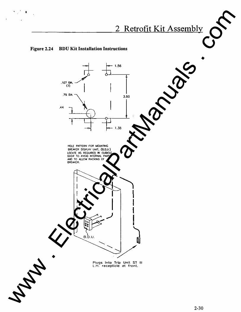
•
2 Retrofit Kit Assembly
Figure 2.24 BDU Kit Installation Instructions
HOLE PATIERN fOR L40UNTING BREAKER DISPLAY UNIT, {B.O.U.)
LOCATE AS REQUIRED IN CUBICLE DOOR TO AVOIO INTERNAL PARTS AND TO ALLOW RACKING Of BREAKER.
� ,) � B . D . U .
1 .56
3:80
1 .38
Plugs into Trip Unit ST Il l L . H . recepticle ot front.
2-30
www . El
ectric
alPar
tMan
uals
. com

3 Breaker Testing and Breaker Labeling
3 Breaker Testing and Breaker Labeling
3.1 General Test Description The test procedures described in this section apply to Static Trip ill Retrofit Kits for Westinghouse type DB and DBL circuit breakers.
Test recommendations descnoed in this section focus on electrical clearance testing of the new componentS involved and the assurance that the newly installed breaker trip circuit is functioning properly. The test procedures descn'bed do not cover and breaker performance testing; breaker performance testing, means to test whether or not a breaker is still capable of meeting its interruption rating as expressed on its rating plate. It is the respo!lSl'bllity of the retrofitter to inspect, test and petform and necessary work to confirm the electrical and mechanical integrity of the breaker. The retrofit Kit components when properly installed per our procedures have no impact on breaker performance. Breaker . performance is simply a function of the overall breaker condition.
3.2 Testing Completely read and understand the Danger, Warning and Safety Instructions on page i of this manual before attempting operation, maintenance or modification of the equipment discussed in this manual.
A DANGER.· �/ / / /
Hozor<loue Volt� 111'.11 couu -• lnj...-y or cleolh.
P.o<SQIW>el conducllng thOs teet procedu<e rnu4l be (tolned in the use of electrlcol te$( � ·� ldlogM 9'�1., 1hon 600 "'GGts. � rnvtll �IOftd Oftd b. fo...-., ..;{h IIOI'dy prfCOUilons ond prooedurH o� lo wch test.
3.3 Low Frequency Withstand Test Low Frequency Withstand Test is in accordance with-ANSI C37.59-1991 (Requirements for Conversion ofPower Switchgear Equipment) and C37.50-1989 (Low-Voltage AC Power Circuit Breakers Used in Enclosures - Test Procedures).
I . Apply ground potential to all secondary disconnects and also ground all trip unit terminals at the top of the Static Trip ill device.
3-1
www . El
ectric
alPar
tMan
uals
. com

3 Breaker Testing and Breaker Labeling
2. Jumper upper primary disconnects, jumper lower disconnects and apply 1320 V AC for one (1) minute between the jumpered primary disconnects with the breaker in the open position. Some more sensitive highpots may buzz or trip due to magnetizing current of the PT module, if installed. In such case the PT module fuses may be removed for this test.
Breaker must pass Low Frequency Withstand Test, otherwise, determine cause of failure, correct the problem and retest.
3. Jumper all six primary disconnects. Leave all other ground jumpers in place and apply 1320 VAC for one {1) minute betweenjumpered primary disconnects and ground.
Breaker must pass Low Frequency Withstand Test, otherwise, determine cause of failure, correct the problem and retest.
4. Jumper top and bottom primary disconnects ofPhase B and Phase C (four (4) tenninals jumpered) and connect to ground. Jumper upper to lower primary disconnect of Phase A and apply 1320 VAC for one (1) minute between Phase A and ground.
Breaker must pass Low Frequency Withstand Test, otherwise, determine cause of failure, correct the problem and retest.
5. Repeat step 4 for voltage applied to Phase B, jumper Phase A to Phase C.
6. Repeat step 4 for voltage applied to Phase C, jumper Phase A to Phase B.
1. Repeat steps 4, 5 and 6 with the breaker closed.
Breaker must pass Low Frequency Withstand Test, otherwise, determine cause of failure, correct the problem and retest.
8. Remove all previous jumpers with the exception of the jumpers on the communication disconnects and trip unit termihals. The jumpers should still be connected to ground. Jumper all six (6) primary disconnects and connect to ground. Jumper all secondary disconnects and apply 600 V AC for one minute between the secondary disconnect and ground. The breaker may be open or closed for this test. This test will assure that the motor (on electrically operated breakers only) is in good operating condition .
. Breaker must pass Low Frequency Withstand Test, otherwise, determine cause of failure, correct the problem and retest.
9. Disconnect the motor leads and repeat step 6, except using 900 VAC instead of 600 V AC for one minute.
3-2
www . El
ectric
alPar
tMan
uals
. com

3 Breaker Testing and Breaker Labeling
Breaker must pass Low Frequency Withstand Test, othenvise, determine cause of failure, correct the problem and retest.
10. Remove all previous jumpers. Reconnect as follows:
• all six (6) primaries to ground • all communication disconnects to ground • all secondary disconnects to ground • disconnect the "ground" wire on Static Trip lli C versions • jumper tenninal one (1) through eight (8) on the trip unit terminal block
Apply 300 V AC for one minute between trip unit jumper and ground.
Breaker must pass Low Frequency Withstand Test, otheiWise, determine cause of failure, correct the problem and retest.
3.4 Trip Unit Testing Testing of the trip unit is descnoed in Static Trip lli trip unit Bulletin SG3 1 18-01, pages 29-3 5. The bulletin is enclosed.
3.5 Labeling ANSI/IEEE C37.59-1991(Requirements for Conversion ofPower Switchgear Equipment) requires a nameplate with the converter (retrofitter) name, address, identification number, date, and rating infonnation. The Retrofit Basic Trip Kit incudes a partially completed nameplate desribing the Siemens Retrofit Kit. The converter (retrofitter) must complete the remaining information (see figure 3 . 1).
Figure 3 . 1 Converted By Label
SIEMENS T����r=======�J:���ri�ol_��· �'------�1 Trip W/0 1,._ _____ --i Comm W/01 �nSOf Rotin
��-
:---=-To-p-r.U�se<l-:--r-1
--t Mfg.Dote E3 Grd. �nsors (when used) I lnst.Book Siemens Energy & Automotion. Inc. Ro16iqh. NC Uode in USA
�=ed By
I I Address �- =========��:=:;:=�::======! 10 �. .__ ___ �I Mfg. Dote �I __ ___,
3-3
: � !, . - · . • .
www . El
ectric
alPar
tMan
uals
. com