si units, symbols and dimensioning - brammer - · pdf filecommon pneumatic symbols 459 n 460...
TRANSCRIPT
457
12
SI units, symbols and dimensioning
12
458
459
460
460
461
462
463
465
466
467
469
470
471
472
474
Sub
ject
to
cha
nge
SI unITS, SyMBOlS AnD DIMEnSIOnInG
Common pneumatic symbols
numbering of connections
Thread sizes
Expressions and definitions
SI units and designations
units for flow
Dimensioning
Flow in tubing and fittings
Average air consumption
Maximum air flow
Quick selection for choosing right flow
Lifting force of vacuum pads
Evacuation time of vacuum pads
Mass moment of inertia
Contents

12
459
Sub
ject
to
cha
nge
SI unITS, SyMBOlS AnD DIMEnSIOnInG
Common pneumatic symbolsSupply of compressed air (1 or P)
Exhaust (3, 5 or E, R)
Silencer
Flow controller
Adjustable flow controller
Filter with manual water drain
Filter with automatic water drain
Pressure regulator with secondary exhaust
Lubricator
FRL – filter/regulator/lubricator-assembly
Single acting cylinder with spring return
Double acting cylinder
Double acting cylinder with magnetic piston for sensors
Double acting cylinder with adjustable cushioning at both end positions
Double acting cylinder with magnetic piston for sensors and adjustable cushioning at both end positions
Rotary actuator
Valve control, general symbol
Valve control, roll
Valve control, spring
Valve control, push button
Valve control, pilot valve
Valve control, direct acting solenoid
Valve control, solenoid pilot valve
Check valve
OR valve
AND valve
Quick exhaust valve
Adjustable speed controller
3/2 valve, normally closed, mono stable, pressure-controlled with spring return
2/2 valve, normally closed, mono stable, push button-controlled with spring return
3/2 valve, normally closed
3/2 valve, normally open
5/2 valve, bi stable
5/2 valve, mono stable
5/3 valve, closed center
5/3 valve, open center
5/3 valve, pressurized center
Double 3/2 valve, normally closed/normally closed
Double 3/2 valve, normally closed/normally open
Double 3/2 valve, normally open/normally open
13
2
12
1
2
13
2
13
2
1 35
24
1 35
24
5 1 3
4 2
5 1 3
4 2
5 1 3
4 2
1 1
2
1 1
2
3 1
2
1 2
1 3
2
5
4
1 3
2
5
4
1 3
2
5
4

12
460
M3 3 mm 2.5 mmM5 5 mm 4.2 mm1/8" 01 R6 9.7 mm 8.6 mm1/4" 02 R8 13.2 mm 11.4 mm3/8" 03 R10 16.7 mm 15 mm1/2" 04 R15 21 mm 18.6 mm3/4" 06 R20 26.4 mm 24.1 mm1" 10 R25 33.2 mm 30.3 mm
1 1/4" 12 R32 41.9 mm 39.8 mm1 1/2" 14 R40 47.8 mm 44.8 mm
2" 20 R50 59.6 mm 56.7 mm
0 3010 40 6020 50 70 mm
Sub
ject
to
cha
nge
SI unITS, SyMBOlS AnD DIMEnSIOnInG
numbering of connectionsExplanation of how the different connections on the pneumatic components are named.
Thread sizes
Port number:1 (P) Inlet, usually related to mains air supply.2 (B) Outlet to consumers.3 (r, E) Drain exhaust.4 (A) Outlet to consumers.5 (r, E) Drain exhaust.
10 Connection for impulse that closes the valve. Only 3/2 n.O.
12 Connection for impulse that combines inlet 1 with outlet 2.
14 Connection for impulse that combines inlet 1 with outlet 4.
■ Single digit even numbers indicates the outlet.■ Single digit odd numbers (except 1) indicate exhaust.■ Double digits indicating controlling connections.
Thread designationOutside diameter Inside diameter
SMC’s part number provides information on the thread. In chapter 10 you will find KQ2 fittings. The last posi-tions in the order number indicate the type of thread. Here you can see what they stand for:
u01 unI-thread. Fits tapered, nPT, straight threads. Disc for sealing.
01S Taper thread. Also fits straight thread. Sprayed PTFE on the threads to seal.
G01 Straight thread. Disc for sealing.M3/M5 Metric thread. Disc for sealing.
Other definitions exist depending on the brand.
1, P
1P
3, R
5R
3R
4, A14PA PB
2, B122, B
1, P3, R
2, B
r1/8
r1/4r3/8
r1/2

12
461
Sub
ject
to
cha
nge
SI unITS, SyMBOlS AnD DIMEnSIOnInG
Expressions and definitionsA short glossary of common terms and definitions in pneumatics.
CylindersDouble acting cylinder where the piston movement
in both directions occurs through the influence of pressurized medium.
Single acting cylinder where the piston movement in one direction is done by the influence of pressurized medium and in the other direction by some other force (spring).
Cylinder end cover the end caps that limit the piston movement in the cylinder.
Piston rod the part that is firmly connected to the pis-ton and passes through one end or both ends.
Extension when the piston rod moves out of the cylinder.
retraction when the piston rod moves into the cylinder.
Extended when the piston rod is in its outer end position.
retracted when the piston rod is in its inner end position.
Plus chamber the cylinder chamber, which when pressurized generates extension.
Minus chamber the cylinder chamber, which when pressurized generates retraction.
Valves2/2 valve valve with an inlet and an outlet, can assume
two different positions.3/2 valve valve with an inlet, an outlet and an exhaust,
can assume two different positions.5/2 valve valve with one inlet, two outlets and two ex-
hausts, can assume two different positions.5/3 valve valve with one inlet, two outlets and two ex-
hausts, can assume three different positions.
normally closed valve (n.C.) If the valve is not ac-tivated, the connection between inlet and outlet is closed.
normally closed valve (n.O.) If the valve is not ac-tivated, the connection between inlet and outlet is open.
Bistable valve Missing spring and remains in posi-tion until it is activated. Has two stable positions and “memory”.
Monostable valve Has a spring and returns to its home position when it is not activated.
Directional control valve Valve that can control the flow of alternate routes, or open and close the flow path.
Flow control valve Valve that can regulate the flow volume.
Pressure control valve Valve that can regulate the pressure.
Direct operated The valve is direct activated by hand, foot, or by mechanical means.
Pilot operated The valve is indirect activated by com-pressed air through amplifying a manual, mechanical or electrical signal to the valve stem or spool. A small and easily adjustable valve controls the major valve.
12
462
m kg kilograms mt s
A m2
V m3
v m/sa m/s2
j kgm2
F n newton = kg · m/s2
G n newton = kg · 9.82W j = kg · m2/s2
M nmP W watt = j/s = nm/s
p Pa pascal = n/m2
Vn m3n
Qn m3n/s
10–6 0.000 001 µ10–3 0.001 m10–2 0.01 c10–1 0.1 d101 10 da102 100 h103 1 000 k106 1 000 000 M
0.4 MPa
0.3 MPa
0.2 MPa
0.1 MPa
Sub
ject
to
cha
nge
SI unITS, SyMBOlS AnD DIMEnSIOnInG
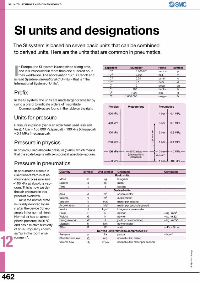
Quantity Symbol unit symbol unit name CommentsBasic units
MassLength meterTime second
Derived unitsArea square meterVolume cubic meterVelocity meter per secondAcceleration meter per second squaredInertia kilogram square meterForceWeightEnergy (work) joule (= newtonmeter)Moment newtonmeterEffect
Derived units related to compressed airPressure Standard volume normal cubic meterVolume flow normal cubic meter per second
SI units and designationsThe SI system is based on seven basic units that can be combined to derived units. Here are the units that are common in pneumatics.
In Europe, the SI system is used since a long time, and it is introduced in more than one hundred coun-tries worldwide. The abbreviation “SI” is French and
is read Système International d’Unités – that is “The International System of units”.
PrefixIn the SI system, the units are made larger or smaller by using a prefix to indicate orders of magnitude.
Common prefixes are found in the table on the right.
units for pressurePressure in pascal (bar is an older term used less and less). 1 bar = 100 000 Pa (pascal) = 100 kPa (kilopascal) = 0.1 MPa (megapascal).
Pressure in physicsIn physics, used absolute pressure (p abs), which means that the scale begins with zero point at absolute vacuum.
Pressure in pneumaticsIn pneumatics a scale is used where zero is at at-mospheric pressure and –100 kPa at absolute vac-uum. This is how we de-fine air pressure in this product overview.
Air in the normal state is usually denoted by an n after the device (for ex-ample ln for normal liters). normal air has an atmos-pheric pressure, is 20 °C and has a relative humidity of 65%. Popularly known as “air in the room envi-ronment”.
Exponent Multiplier Prefix Symbolmicro-milli-centi-deci- deca-hecto-kilo-mega-
(atmospheric pressure)
Physics Meteorology Pneumatics
p =
pre
ssur
evacuum
1013 mbar
500 kPa
400 kPa
300 kPa
200 kPa
100 kPa100 kPa
0 kPa
4 bar
3 bar
2 bar
1 bar
0 bar
–1 bar
0 MPa
–100 kPa

12
463
Cv
f kv Kv
S
CQn
18
270
5
Smm2
kvdm3/min
Kvm3/h
CvuSG/min
fgal/min
Qn
ln/minS 1 0.794 0.048 0.055 0.046 54.53kv 1.259 1 0.06 0.07 0.058 68.65Kv 20.979 16.667 1 1.166 1.035 1 144 Cv 18 14.3 0.858 1 0.829 981.5f 21.7 17.243 0.967 1.206 1 1 184
0.055
16.67
0.06
0.01
5
68.6
5
0.2
54.5
3
0.07 14
.3
0.01
80.001981.5
0.7941.259
1.20
6
0.82
9
0.0037
Sub
ject
to
cha
nge
SI unITS, SyMBOlS AnD DIMEnSIOnInG
In order to determine if a valve has sufficient output for a given application, requires more than knowing the maximum flow. You must also know how a value is
measured in order to use it in the actual case.A valve flow performance depends not only on the
dimensions and geometry of the valve body. The follow-ing variables are significant:
■ The pressure at the output port■ The pressure drop across the valve■ The relationship between this pressure
and the primary pressure■ The temperature
In all cases, based on a data flow performance on the so-called normal volume. It is the volume of air occu-pied at atmospheric pressure, 20 °C and relative humid-ity of 65% (normal air). This volume is frequently given in ln resp nm3. Since newton (n) has been introduced as a unit of force, this writing is no longer correct. Since liter is not an SI unit, volume should be given in dm3
n, and since that unit is unnecessarily complicated, we have chosen ln for simplicity.
In the adjacent chart is shown the international use of the units and their interrelationships. The arrows point-ing to another unit states the conversion factor.
Qn – normal flow rateTo roughly indicate flow, volume is currently used, i.e. the flow that the valve is performing at a primary pres-sure of 6 bar and 1 bar pressure drop across the valve. It is only a rough indication, because the measurement methods and conditions may vary from make to make.
S – equivalent flow areaThe value of S in mm2 is the flow area (holes) in a meas-uring instrument that provides the same pressure drop as a valve or a system of components at the same out-put. SMC specifies this value for each component. It is measured with air as a medium and can be converted to other units, such as kv or Cv factor.
units for flowComparison and conversion between different international flow units.
12
464
Sub
ject
to
cha
nge
SI unITS, SyMBOlS AnD DIMEnSIOnInG
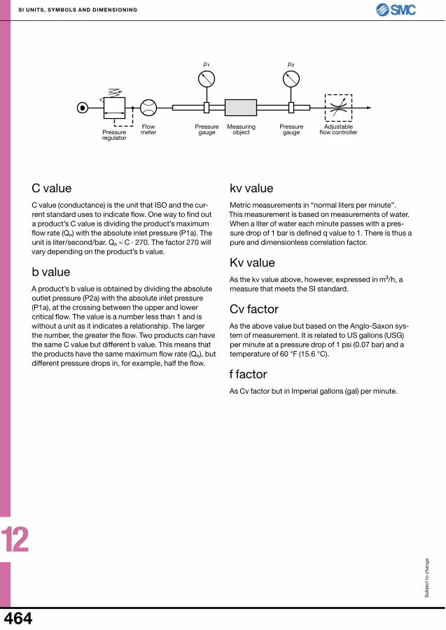
C valueC value (conductance) is the unit that ISO and the cur-rent standard uses to indicate flow. One way to find out a product’s C value is dividing the product’s maximum flow rate (Qn) with the absolute inlet pressure (P1a). The unit is liter/second/bar. Qn ≈ C · 270. The factor 270 will vary depending on the product’s b value.
b valueA product’s b value is obtained by dividing the absolute outlet pressure (P2a) with the absolute inlet pressure (P1a), at the crossing between the upper and lower critical flow. The value is a number less than 1 and is without a unit as it indicates a relationship. The larger the number, the greater the flow. Two products can have the same C value but different b value. This means that the products have the same maximum flow rate (Qn), but different pressure drops in, for example, half the flow.
kv valueMetric measurements in “normal liters per minute”. This measurement is based on measurements of water. When a liter of water each minute passes with a pres-sure drop of 1 bar is defined q value to 1. There is thus a pure and dimensionless correlation factor.
Kv valueAs the kv value above, however, expressed in m3/h, a measure that meets the SI standard.
Cv factorAs the above value but based on the Anglo-Saxon sys-tem of measurement. It is related to uS gallons (uSG) per minute at a pressure drop of 1 psi (0.07 bar) and a temperature of 60 °F (15.6 °C).
f factorAs Cv factor but in Imperial gallons (gal) per minute.
Pressure regulator
Adjustable flow controller
Measuring object
Flow meter
Pressure gauge
Pressure gauge
p1 p2
12
465
0.2 0.3 0.4 0.5 0.6 0.7 0.8 0.9 1.0
6 mm 3 mm 0.28 6 8 11 14 17 20 — — — 0.21 4 6 8 11 13 15 — — —
10 mm 4 mm 0.79 16 24 31 39 47 55 — — — 0.66 13 20 26 33 40 46 — — —
12 mm 6 mm 1.13 23 34 45 57 68 79 90 102 113 0.85 17 25 34 42 51 59 68 76 85
16 mm 6 mm 2.01 40 60 80 101 121 141 161 181 201 1.73 35 52 69 86 104 121 138 155 173
20 mm 8 mm 3.14 63 94 126 157 188 220 251 283 314 2.64 53 79 106 132 158 185 211 238 264
25 mm 10 mm 4.91 98 147 196 245 295 344 393 442 491 4.12 82 124 165 206 247 289 330 371 412
32 mm 12 mm 8.04 161 241 322 402 483 563 643 724 804 6.91 138 207 276 346 415 484 553 622 691
40 mm 16 mm 12.57 251 377 503 628 754 880 1 005 1 131 1 257 10.56 211 317 422 528 633 739 844 950 1 056
50 mm 20 mm 19.63 393 589 785 982 1 178 1 374 1 571 1 767 1 963 16.49 330 495 660 825 990 1 155 1 319 1 484 1 649
63 mm 20 mm 31.17 623 935 1 247 1 559 1 870 2 182 2 494 2 806 3 117 28.03 561 841 1 121 1 402 1 682 1 962 2 242 2 523 2 803
80 mm 25 mm 50.27 1 005 1 508 2 011 2 514 3 016 3 519 4 022 4 522 5 027 45.36 907 1 361 1 814 2 268 2 722 3 175 3 629 4 082 4 536
100 mm 30 mm 78.53 1 571 2 356 3 141 3 927 4 712 5 497 6 282 7 068 7 853 71.47 1 429 2 144 2 859 3 574 4 288 5 003 5 718 6 432 7 147
125 mm 32 mm123 2 450 3 680 4 910 6 150 7 360 8 590 9 820 11 040 12 270115 2 294 3 441 4 588 5 735 6 882 8 029 9 176 10 323 11 470
140 mm 36 mm154 3 080 4 620 6 160 7 700 9 240 10 800 12 300 13 900 15 400144 2 880 4 320 5 760 7 200 8 640 10 100 11 500 13 000 14 400
160 mm 40 mm201 4 020 6 030 8 040 10 050 12 060 14 070 16 080 18 100 20 110189 3 770 5 650 7 540 9 420 11 310 13 190 15 080 16 960 18 850
180 mm 45 mm254 5 080 7 620 10 200 12 700 15 200 17 800 20 300 22 900 25 400239 4 780 7 170 9 560 12 000 14 300 16 700 19 100 21 500 23 900
200 mm 50 mm314 6 280 9 420 12 600 15 700 18 800 22 000 25 100 28 300 31 400295 5 900 8 850 11 800 14 800 17 700 20 700 23 600 26 600 29 500
250 mm 60 mm491 9 820 14 700 19 600 24 600 29 500 34 400 39 300 44 200 49 100463 9 260 13 900 18 500 23 200 27 800 32 400 37 000 41 700 46 300
300 mm 70 mm707 14 100 21 200 28 300 35 400 42 400 49 500 56 600 63 600 70 700668 13 400 20 000 26 700 33 400 40 100 46 800 53 400 60 100 66 800
Sub
ject
to
cha
nge
SI unITS, SyMBOlS AnD DIMEnSIOnInG
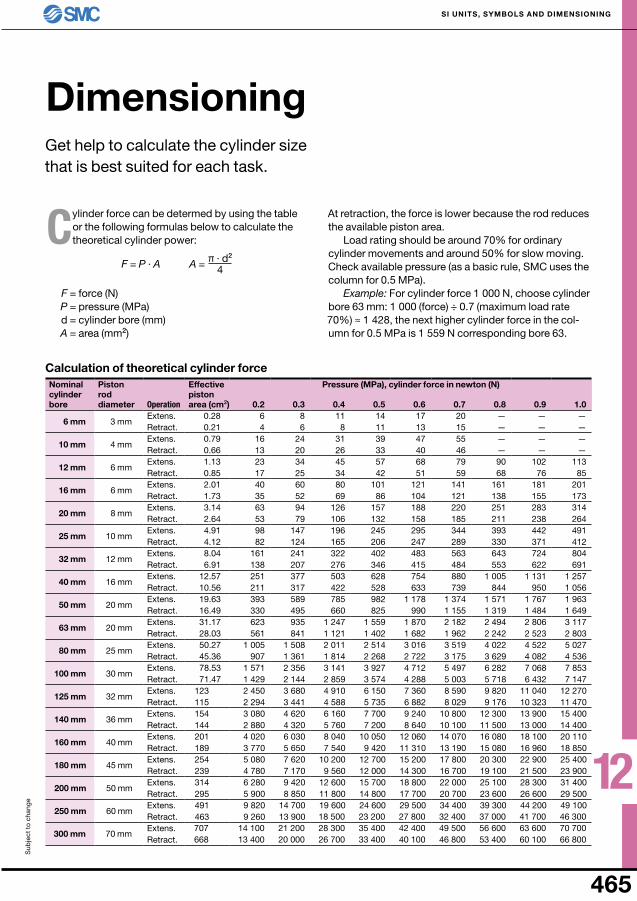
DimensioningGet help to calculate the cylinder size that is best suited for each task.
Calculation of theoretical cylinder forcenominal cylinder bore
Piston rod diameter Operation
Effective piston area (cm2)
Pressure (MPa), cylinder force in newton (n)
Extens.Retract.Extens.Retract.Extens.Retract.Extens.Retract.Extens.Retract.Extens.Retract.Extens.Retract.Extens.Retract.Extens.Retract.Extens.Retract.Extens.Retract.Extens.Retract.Extens.Retract.Extens.Retract.Extens.Retract.Extens.Retract.Extens.Retract.Extens.Retract.Extens.Retract.
Cylinder force can be determed by using the table or the following formulas below to calculate the theoretical cylinder power:
F = force (n) P = pressure (MPa) d = cylinder bore (mm) A = area (mm2)
At retraction, the force is lower because the rod reduces the available piston area.
Load rating should be around 70% for ordinary cylinder movements and around 50% for slow moving. Check available pressure (as a basic rule, SMC uses the column for 0.5 MPa).
Example: For cylinder force 1 000 n, choose cylinder bore 63 mm: 1 000 (force) ÷ 0.7 (maximum load rate 70%) ≈ 1 428, the next higher cylinder force in the col-umn for 0.5 MPa is 1 559 n corresponding bore 63.
F = P · A π · d2
4A =

12
466
0.5 m 1 m 3 m 5 m3.2 mm/2 mm 76 54 35 27
61 48 33 264 mm/2.5 mm 134 101 61 48
98 82 56 456 mm/4 mm 424 333 209 165
314 272 191 1568 mm/5 mm 722 581 374 297
473 426 321 2688 mm/6 mm 1 105 906 596 476
700 641 498 42210 mm/8 mm 2 156 1 826 1 251 1 012
1 083 1 056 958 87912 mm/9 mm 2 780 2 387 1 666 1 355
1 662 1 565 1 419 1 276
Sub
ject
to
cha
nge
SI unITS, SyMBOlS AnD DIMEnSIOnInG
Flow in tubing and fittingsA simple quick reference sheet to calculate the air flow in tubes of varying lengths and dimensions.
the table below shows the air flow in the different tube sizes and lengths. The upper value is only the tubing and lower is the tubing with a straight KQ2H
fitting at one end and a KQ2L elbow fitting at the other end.
The flow (Qn) is given in ln/min. i.e.: In = 0,6 MPa and OuT = 0,5 MPa.
tubing (outer/inner diam.)
with fittings
with fittings
with fittings
with fittings
with fittings
with fittings
with fittings
Note! If you choose tubing with the same flow as the se-lected valve, flow is reduced to 71% of valve capacity.
Example: A VZ3000-valve (196 ln/min) with 3 meters of tube, diameter 6 mm/4 mm (191 ln/min with fittings), provides a flow of about 140 ln/min.
Serial connection w. same flow rates
Serial connection w. diff. flow rates
Parallel connection
1 + 1 71% 2 + 1 89% 1 + 1 21 + 1 + 1 58% 3 + 1 95% 1 + 2 3
1 + 1 + 1 + 1 50% 4 + 1 97% 1 + 3 4
Example: If two components with the same flow (1) are serially connected, the flow is reduced to 71% of what a component normal has.
Serial connection
Parallel connection
= + +1S2
1S1
21
S22
1Sn
2
S = S1 + S2 + Sn

12
467
0.6
1.5 1.5
0.40.5
0.3
0.20.15
0.1
0.050.040.03
0.020.015
0.01
0.20.3
0.40.8
0.6
0.50.7
Sub
ject
to
cha
nge
SI unITS, SyMBOlS AnD DIMEnSIOnInG
Average air consumptionHow to calculate the average air consumption of cylinders and air lines.
you need to know the average air consumption to determine the compressor size and running cost.
Here we show how to use the charts on this page to calculate the average air consumption of cylin-ders and air lines.
Example:Cylinder bore: 50 mmStroke: 600 mmWorking pressure: 0.5 MPaWork cycles: 5 cycles per minuteAir tubing inner diameter: 6 mmAir tubing length: 2 m
Air consumption of cylinder1. use chart 1 and find the point where the working
pressure line (0.5 MPa) crosses the stroke line (600 mm). See point A.
2. From point A, go straight up until you cross the bore line (50 mm). See point B.
3. From there, go horizontally to the right or the left and find air consumption per cycle (Qt) = 13 ln.
4. Since there are five working cycles per minute, multiply the air consumption per cycle (Qt) with 5 to get the actual average air consumption (Qv).
Qv = Qt ∙ number of cycles per minuteQv = 13 ln/min ∙ 5Qv = 65 ln/min
Chart 1 – cylinder air consumption per cycle
Single stroke (extension or retraction)
Working pressure (MPa)
Str
oke
(mm
)A
ir co
nsum
ptio
n p
er c
ycle
(ln)
Air
cons
ump
tion
per
cyc
le (l
n)
Cylinder bore (mm)
Double stroke = cycle (extension and retraction)
1 5002 000 2 000
1 000
500400300
200150
100
504030
2015
10
543
2
1
1 500
1 000
500400300
200150
100
504030
2015
10
543
2
1
5 0004 0003 000
2 0001 500
1 000
50
100
150200
300400500
16012510080
63
504032
25
2016
10
6
16012510080
63
504032
25
2016
10
6
16012510080
63
504032
25
2016
10
6
16012510080
63
504032
25
2016
10
6
A
B
12
468
20
10
54
3
2
1
20
10
54
3
2
1
10
54
3
2
1
12
98
6
5
4
12
98
6
5
4
12
98
6
5
4
12
98
6
5
4
C
D
0.3
0.3
0.40.5
1.5
0.2
0.40.5
0.3
0.2
0.1
0.050.04
0.03
0.02
2.5
2.5
7.5
7.5
0.01
0.005
0.40.5
0.20.3
0.8
0.40.5
0.60.7
Sub
ject
to
cha
nge
SI unITS, SyMBOlS AnD DIMEnSIOnInG
Chart 2 – air tubing air consumption per cycle
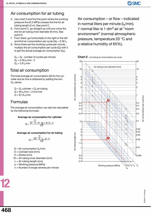
Air consumption for air tubing5. use chart 2 and find the point where the working
pressure line (0.5 MPa) crosses the line for air tubing length (2 m). See point C.
6. From point C, go straight up until you cross the line for air tubing inner diameter (6 mm). See point D.
7. From there, go horizontally to the right or the left and find air consumption per cycle (Qt) = 0.56 ln.
8. Since there are five working cycles per minute, multiply the air consumption per cycle (Qt) with 5 to get the actual average air consumption (Qv).
Qv = Qt ∙ number of cycles per minuteQv = 0.56 ln/min ∙ 5Qv = 2.8 ln/min
Total air consumptionThe total average air consumption (Q) for the cyl-inder and air line is obtained by adding the two Qv values.
Q = Qv cylinder + Qv air tubingQ = 65 ln/min + 2.8 ln/minQ = 67.8 ln/min
FormulasThe average air consumption can also be calculated by the following formulas:
Average air consumption for cylinder
Average air consumption for air tubing
Q = Air consumption (ln/min) D = Cylinder bore (mm) H = Stroke (mm) ID = Air tubing inner diameter (mm) L = Air tubing length (mm) p = Working pressure (MPa) n = number of single strokes per minute
Air consumption – or flow – indicated in normal liters per minute (ln/min). 1 normal liter is 1 dm3 air at “room environment” (normal atmospheric pressure, temperature 20 °C and a relative humidity of 65%).
Working pressure (MPa)
Air
tub
ing
leng
th (m
)A
ir co
nsum
ptio
n p
er c
ycle
(ln)
Air
cons
ump
tion
per
cyc
le (l
n)
Air tubing inner diameter (mm)
D2 · 4 · H · (p + 0.1) · n105
π
Q =
ID2 · 4 · L · p · n105
π
Q =
12
469
0.5
0.20.3
0.40.5
0.70.8
0.6
Sub
ject
to
cha
nge
SI unITS, SyMBOlS AnD DIMEnSIOnInG
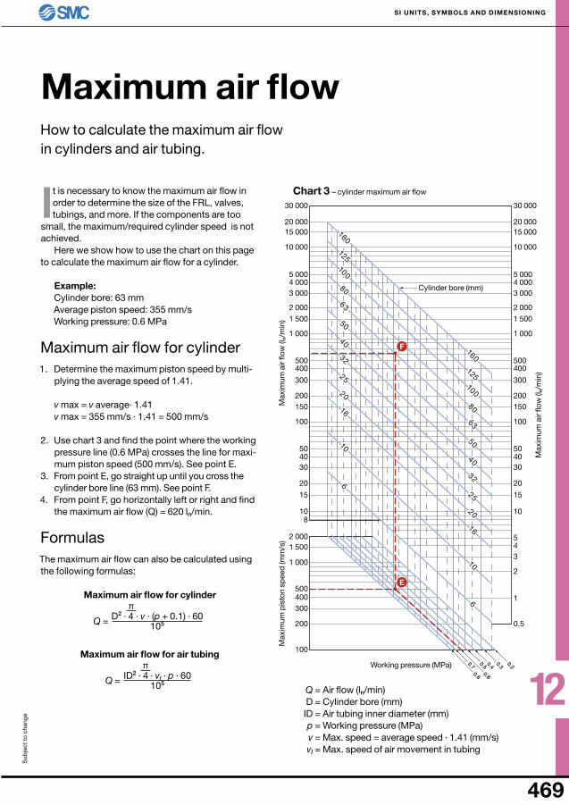
Chart 3 – cylinder maximum air flow
Maximum air flowHow to calculate the maximum air flow in cylinders and air tubing.
It is necessary to know the maximum air flow in order to determine the size of the FRL, valves, tubings, and more. If the components are too
small, the maximum/required cylinder speed is not achieved.
Here we show how to use the chart on this page to calculate the maximum air flow for a cylinder.
Example:Cylinder bore: 63 mmAverage piston speed: 355 mm/sWorking pressure: 0.6 MPa
Maximum air flow for cylinder1. Determine the maximum piston speed by multi-
plying the average speed of 1.41.
v max = v average∙ 1.41v max = 355 mm/s ∙ 1.41 = 500 mm/s
2. use chart 3 and find the point where the working pressure line (0.6 MPa) crosses the line for maxi-mum piston speed (500 mm/s). See point E.
3. From point E, go straight up until you cross the cylinder bore line (63 mm). See point F.
4. From point F, go horizontally left or right and find the maximum air flow (Q) = 620 ln/min.
FormulasThe maximum air flow can also be calculated using the following formulas:
Maximum air flow for cylinder
Maximum air flow for air tubing
Q = Air flow (ln/min) D = Cylinder bore (mm) ID = Air tubing inner diameter (mm) p = Working pressure (MPa) v = Max. speed = average speed ∙ 1.41 (mm/s) vl = Max. speed of air movement in tubing
Working pressure (MPa)
Max
imum
pis
ton
spee
d (m
m/s
)M
axim
um a
ir flo
w (l
n/m
in)
Max
imum
air
flow
(ln/
min
)
Cylinder bore (mm)
D2 · 4 · v · (p + 0.1) · 60105
π
Q =
ID2 · 4 · vl · p · 60105
π
Q =
2 000
3 0004 0005 000
10 000
15 00020 000
30 000
1 500
1 000
500400
300
200150
100
504030
20
15
10
2 000
3 0004 0005 000
10 000
15 00020 000
30 000
1 500
1 000
500400
300
200150
100
504030
20
15
108
543
2
1
1 000
1 5002 000
100
200
300400500
160
125100
80
63
50
40
32
25
20
16
10
6
160
125100
80
63
50
40
32
25
20
16
10
6
160
125100
80
63
50
40
32
25
20
16
10
6
160
125100
80
63
50
40
32
25
20
16
10
6
E
F

12
470
100 200 300 400 500 600 700 800 900 1000 20 10 30 40 50 60 70 80 90 100 120 25 20 40 60 70 90 110 130 140 160 180 32 30 60 90 120 150 180 210 230 260 290 40 50 90 140 180 230 270 320 370 410 460 50 70 140 210 280 360 430 500 570 640 710 63 110 230 340 450 560 680 790 900 1 010 1 130 80 180 360 550 730 910 1 090 1 270 1 450 1 630 1 810100 290 570 850 1 130 1 420 1 700 1 980 2 260 2 550 2 830125 440 880 1 320 1 770 2 210 2 650 3 090 3 530 3 970 4 420140 550 1 110 1 660 2 220 2 770 3 320 3 880 4 430 4 990 5 540160 720 1 450 2 170 2 890 3 620 4 340 5 060 5 790 6 510 7 230180 920 1 830 2 750 3 660 4 580 5 490 6 410 7 320 8 240 9 160200 1 130 2 260 3 390 4 520 5 650 6 780 7 910 9 040 10 170 11 300250 1 770 3 530 5 300 7 070 8 830 10 600 12 360 14 130 15 900 17 660300 2 540 5 090 7 630 10 170 12 720 15 260 17 800 20 350 22 890 25 430
Sub
ject
to
cha
nge
SI unITS, SyMBOlS AnD DIMEnSIOnInG
Quick selection for choosing right flowIf you do not make an estimate of cylinder air consumption by the methods shown on previous pages, the following speed selection table provide benchmarks for dimensioning.
NThe table below shows the maximum air flow (in normal liters per minute [ln/min]) a cylinder needs. This value depends on the cylinder piston diam-
eter and operating speed.The table is applicable at a pressure of 0.5 MPa and
the rate used is the maximum speed/end speed.If you know the average speed and want to know the
maximum speed you get a proxy if you multiply the aver-age speed of 1.4.
v max ≈ v average ∙ 1.4
Example:A cylinder with a bore of 32 mm is moving at max. 300 mm/s. According to the table, the cylinder needs a flow of 90 normal liters per minute.
Should you choose a suitable filter, regulator, valve and tubing you can not select these compo-
Air flow requirement for cylinder – ln/min, at a pressure of 0.5 MPa
Bore (mm)
Maximum cylinder speed (mm/s)
nents with a flow rate of about 90 normal liters per minute. If you do, the pressure drop is too large, and the flow into the cylinder is halved. Any components before the cylinder is like a long chain, producing constrictions and losses.
As a general rule you can say that the pressure drop is max. 0.03 MPa of each component. To get the right flow to the cylinder, each component must handle much more in flow. A rough guideline is that each component shall have four times greater flow than the cylinder needs.
Since 4 ∙ 90 is 360, the filter, the regulator and all the other components should have a flow of about 400 normal liters per minute.
The beginning of chapter 4 contains tables that can also be useful when dimensioning.

12
471
2 mm 4 mm 6 mm 10 mm 16 mm 20 mm 25 mm 32 mm 40 mm 50 mm0.031 0.126 0.238 0.785 2.01 3.14 4.91 8.04 12.6 19.6
–86 kPa –650 mmHg 0.27 n 1.09 n 2.45 n 6.8 n 17.4 n 27.2 n 42.5 n 69.7 n 109.2 n 169.8 n–80 kPa –600 mmHg 0.25 n 0.98 n 2.26 n 6.3 n 16.1 n 25.1 n 39.3 n 64.3 n 100.8 n 156.7 n–73 kPa –550 mmHg 0.23 n 0.92 n 2.07 n 5.8 n 14.7 n 23 n 36 n 58.9 n 92.4 n 143.7 n–66 kPa –500 mmHg 0.21 n 0.84 n 1.89 n 5.2 n 13.4 n 20.9 n 32.7 n 53.6 n 84 n 130.6 n–60 kPa –450 mmHg 0.19 n 0.76 n 1.7 n 4.7 n 12.1 n 18.8 n 29.5 n 48.2 n 75.6 n 117.6 n–53 kPa –400 mmHg 0.17 n 0.67 n 1.51 n 4.2 n 10.7 n 16.7 n 26.2 n 42.9 n 67.2 n 104.5 n–46 kPa –350 mmHg 0.14 n 0.59 n 1.32 n 3.7 n 9.4 n 14.6 n 22.9 n 37.5 n 58.8 n 91.5 n–40 kPa –300 mmHg 0.12 n 0.5 n 1.13 n 3.14 n 8 n 12.6 n 16.9 n 32.1 n 50.4 n 78.4 n
100 kPa = 0.1 MPa = 1 bar = 1 000 mbar
Sub
ject
to
cha
nge
SI unITS, SyMBOlS AnD DIMEnSIOnInG
lifting force of vacuum padsHow to calculate the theoretical lifting force of vacuum pads at different vacuum.
F = Lifting force with safety factor (n) A = Pad area (cm2) t = Safety factor (horizontal contact surface: 2–4;
vertical contact surface: 4–8)
As a complement to these formulas, you can find the lift-ing force at different vacuum in the table below.
Note! The values you get from the table should be multiplied by 1
t as in the above formulas.
Calculation of theoretical lifting forceVacuum pad diameterVacuum pad area (cm2)
Vacu
um
to be able to choose the correct dimensions on the vacuum pads, you should know the different vacuum pads theoretical lifting force at different vacuum levels.
Here we present formulas and a table that you can use as a basis for your calculations.
Vacuum pad
Vacuum pad
Horizontal contact
Vertical contact
FormulasVacuum in kPa
P = Vacuum (kPa)
Vacuum in mmhg
P = Vacuum (mmHg)
F = P · A · 1t ÷ 10 F = P ÷ 760 · A · 1
t · 10.13
W
W

12
472
1
235
1020
50S
L1 2 3 5 10 20
8
654
3
2
8
654
3
2
1.0
0.5
0.95
0.63
2.5
4.5
6.57.5
2.18
0.5
0.5
0.30.2
Sub
ject
to
cha
nge
SI unITS, SyMBOlS AnD DIMEnSIOnInG
evacuation time of vacuum padsHow to calculate evacuation time for vacuum pads, and choosing ejector and tubing.
Here we show, using formulas and charts, how to calculate how long it takes for a vacuum pad to achieve the desired vacuum level.
Calculation of evacuation timeAverage suction flow in ejector
Q1 = 0.4 · Qmax
Tubing maximum flow
Q2 = S · 11.1
Tubing volume between ejector and vacuum pad
V = 1 ÷ 1 000 · π ÷ 4 · D2 · L
Evacuation time
T1 = V · 60 ÷ QT2 = 3 · T1
Example:Ejector: ZH10BS-06-06Max. vacuum (PV): –88 kPaMax. suction flow (Qmax): 24 l/minTubing length (L): 1 mTubing inner diameter (D): 6 mmVacuum pad diameter: 10 mmnecessary vacuum: 63% of PV, no leakage
1. Calculate ejector’s average suction flow (Q1) by mul-tiplying the maximum suction flow by 0.4.
Q1 = 0.4 · 24 l/min = 9.6 l/min
2. Calculate maximum tubing flow (Q2) by finding the tubing’s equivalent cross-sectional area (S) in chart 4 and multiplying this by 11.1.
Q2 = 18 · 11.1 = 198 l/min
3. Calculate tubing volume between ejector and pad.
V = 1 ÷ 1 000 · π ÷ 4 · 62 · 1 = 0.028 l
4. Calculate evacuation time. Since Q1 is lower than Q2 this means Q = Q1 i.e. 9.6 l/min. The time to reach 63 % of max. vacuum equals:
T1 = 0.028 · 60 ÷ 9.6 = 0.18 s
Chart 4 – tubing equivalent cross-sectional area Qmax = Ejector’s maximum suction flow (l/min), see the technical data
S = Tubing equivalent cross-sectional area (mm2), see chart 4
V = Tubing volume (l) between ejector and vacuum pad
T1 = Time (s) to reach 63% of maximum vacuum level (PV)
T2 = Time (s) to reach 95% of maximum vacuum level (PV)
Q = The lowest of Q1 and Q2
Pressure (vacuum)
Vacu
um (P
V)
Time
Tubing length (m)
Tubing inner diameter (mm)
Eq
uiv.
cro
ss-s
ectio
n (m
m2 )
1
PV ·
PV ·
0 2 3 4
T1 T2

12
473
Sub
ject
to
cha
nge
SI unITS, SyMBOlS AnD DIMEnSIOnInG
Individual control of ejector and release
Switching between vacuum and release
Switching between vacuum and release
– on suction side
Common exhaust
Connection examples
InstructionsSupply connection (supply): Dimension supply line, valves and connections considering the ejector’s air consumption (see technical data).
Vacuum ejector (vac): the tubing between ejector and vacuum pad should be as short as possible. Filters should be installed for use in dusty environment (dust).
Ejector exhaust connection (exh): Type B – do not block the silencer. Type D – do not connect longer tub-ing that 0.5 meter (= pressure < 5 kPa).
number of vacuum pads: One vacuum pad per ejector for maximum safety.
EXH

12
474
a12
3J = m1 · + m2 ·a2
2
3
abJ = ( )2 JB + JB
a2
12J = m ·
a2
12J = m ·4a1
2 + b2
12J = m1 · + m2 ·4a2
2 + b2
12
a2 + b2
12J = m · r2
2J = m ·
2r2
5J = m ·r2
4J = m ·
a12
3J = m1 · + m2 · a22 + K
2r2
5K = m ·
Sub
ject
to
cha
nge
SI unITS, SyMBOlS AnD DIMEnSIOnInG
Mass moment of inertiaWhen dimensioning a rotary actuator you must, in addition to necessary torque, also consider the load’s mass moment of inertia. For your aid, please find the formulas below (dimensions in meters).
1. Thin axle, excentrically suspended
3. Thin rectangular plate, on edge and centered
5. Thin rectangular plate, lying down and centered
7. Sphere (ball), centered
2. Thin axle, centered suspension
4. Thin rectangular plate, lying down and excentrically suspended
6. Thin disc, lying down and centered
8. Thin disc, on edge and centered
9. Thin axle with mass
When m2 is spherical, K equals, as in case 7:
10. TransmissionFirst calculate mass moment of inertia for gears A and B (as in case 6) and then:
no of teeth = a
no of teeth = b
If the axle is carrying a disc, calculate K as in case 6 or 8.
a2
a1
a
a1
a2ba
b
a b
r
r r
a2 r
a1
m1
m2
(A)
(B)