shop online at omega · shop online at omega.com user’s guide. the information contained in this...
TRANSCRIPT
e-mail: [email protected] latest product manuals:
www.omegamanual.info
OM-90 SERIESPortable Temperature and
Humidity Data Loggers
TM
Shop online at omega.com
User’s Guide

The information contained in this document is believed to be correct, but OMEGA accepts no liability for any errors it contains, and reserves the right to alter specifications without notice.
omega.com [email protected]
Servicing North America:U.S.A. Omega Engineering, Inc. Headquarters: Toll-Free: 1-800-826-6342 (USA & Canada only) Customer Service: 1-800-622-2378 (USA & Canada only) Engineering Service: 1-800-872-9436 (USA & Canada only) Tel: (203) 359-1660 Fax: (203) 359-7700 e-mail: [email protected] For Other Locations Visit omega.com/worldwide
Revision 1.0.5 Page 2
User Guide
Contents1. Document Overview ............................................................................................... 3
2. Product Overview ................................................................................................... 4
3. Technical Specifications .......................................................................................... 6
4. Buttons and LED Indicators ..................................................................................... 7
5. Packaging List ....................................................................................................... 8
6. Installation of the Software ..................................................................................... 9
7. Using the Software ............................................................................................... 10
7.1. Front Page .................................................................................................... 10
7.2. Main Page ..................................................................................................... 11
7.3. Configuration of a Data Logger (Start on Disconnection) ...................................... 12
7.4. Saving a Configuration File .............................................................................. 14
7.5. Loading a Configuration from File ..................................................................... 15
7.6. Retrieving Logged Data ................................................................................... 16
7.7. Viewing Logged Data from File ......................................................................... 17
7.8. Configuration of a Data Logger (Start at Specified Time) ...................................... 19
7.9. Configuration of a Data Logger (Start using Button Press) .................................... 20
7.10. Configuration of a Data Logger (Real Time Logging) ............................................ 21
8. Mounting Guidelines ............................................................................................. 22
9. Battery Replacement ............................................................................................ 22
10. Technical Support ............................................................................................. 22

Revision 1.0.5 Page 3
1. Document Overview
This guide is provided to distribute the following information:
the main features of data logger how to install the software for the logger how to use the software for configuration, data extraction and data viewing how to mount your data logger how to replace the battery for the data logger contact information should you have further technical questions

Revision 1.0.5 Page 4
2. Product Overview
The OM-90 Series are compact temperature / humidity data loggers measuring just 35mm x 60mm x 15mm. These data loggers are commonly used in transport applications including but not limited to transport of:
sensitive/fragile items food animal/livestock plants chemicals medicines or organs
The OM-90 Series comes in two versions; OM-91 is a temperature only version and OM-92 is a temperature and humidity logger. This document applies for both versions.
Figure 1: Introducing the OM-90 Series Data Loggers and software
Suppose for example you would like to transport some delicate or fragile cargo from one location to another. By attachment of a data logger one can record temperature and humidity conditions during the journey. At the destination you can then extract the logged data using very simple software and see graphically or in raw data format the changes in environment over time.
When you would like to guarantee that items are transported within particular environmental limits then one can also set operating ranges above or below which light indicators will be activated so that the user can become aware that the desired transportation conditions have been exceeded.

Revision 1.0.5 Page 5
Figure 2: Data Logger Indicators
The data logger offers accurate and repeatable logging for temperature and relative humidity. Temperature is measured to an accuracy of +0.3oC over the range +5oC to +60oC. Over the full range -30oC to +80oC the accuracy is +2.0oC. Relative humidity is measured to an accuracy of +2.0% over 20% to 80% humidity range and +3.0% over 0% to 100%. Both temperature and relative humidity are logged at a user configurable logging rate which can be set in software.
The data logger is equipped with the largest logging memory when compared with comparable portable logging devices currently available. The data logger has provision for an impressive 65520 records, each of which is a time-stamped recording of temperature and humidity.

Revision 1.0.5 Page 6
-30oC to +80oC (-22o F to 176o F)+0.3oC (+5oC to +60oC)+0.5o F (41oF to 140oF)see accuracy curve in figure 30.01oC (0.2o F)
0% to 100% +2.0% (20% to 80%)see accuracy curve in figure 30.01%
CR2540 coin cell up to 4 years while logging
35mm x 60mm x 15mm
16 characters
3. Technical Specifications
Temperature range Temperature accuracy (limited range)
Temperature accuracy (-30oC to +80oC) Temperature resolution
Humidity range (only on OM-92) Relative humidity accuracy (limited range) Relative humidity accuracy (0% to 100%) Relative humidity resolution
Temperature alarms (minimum & maximum) Relative humidity alarms (minimum & maximum)
Battery Battery life
Physical size
Software available on Windows XP, Vista, Windows 7, 8 & 10 (coming soon to Linux & MacOs)
Logger identifier
Logging space (includes time plus temperature & humidity) 65520 points
Figure 3: Temperature and Humidity Accuracy

Revision 1.0.5 Page 7
4. Buttons and LED Indicators
The data logger includes one button located on the side of the logger. It is possible by configuration in the software to use this button as a way to start and stop logging. See section 7.9 Configuration of a Data Logger (Start using Button Press)
Figure 4: Data Logger Start/Stop Button
The logger contains two LED indicators - LED left and LED right with the following functionality:
Status LED
When the logger starts logging then this LED pulses green once for 1 second. When logging this LED pulses green for 7 milliseconds and off for 6 seconds. When the logger stops then this LED pulses red for 1 second then off forever.
Alarm LED
When a temperature or humidity alarm is triggered this LED pulses red for 7 milliseconds and off for 6 seconds.
Figure 5: Data Logger LED indicators

Revision 1.0.5 Page 8
5. Packaging List
Your data logger comes standard with the following items.
One Data Logger unit (either OM-91 or OM-92)
Figure 6: Data Logger Unit
One CR2450 coin cell battery
Figure 7: CR2450 Coin Cell Battery and Install CD
One USB cable – type A to micro-USB type B
Figure 8: USB Cable
One installation CD (Software is also available for download on the OM-90 web page)
Revision 1.0.5 Page 9
6. Installation of the Software
Installation of the software is very simple. The data logger needs no special drivers since it is a USB HID device and such devices can make use of the standard drivers that come with Windows. Simply install the software from the CD included with the data logger.
In order to use this software consult the next section – Section 7 "Using the Software".
OR download and install the software from Omega's OM-90 web page. (look for the software icon).

Revision 1.0.5 Page 10
7. Using the Software
7.1. Front Page
When the software is started the welcome screen appears and gives a brief introduction to the data loggers and what they can be used for.
Click on the Configuration Wizard Button to start configuration of the logger. Click on the Graph Button if you want to view data graphically. Click on the Raw Data Button if you want to view logger data as a table.
Figure 9: OM-90 Series Data Logger Software
Revision 1.0.5 Page 11
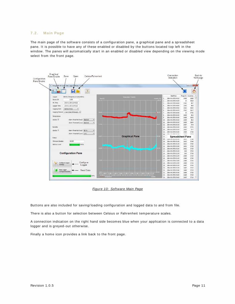
7.2. Main Page
The main page of the software consists of a configuration pane, a graphical pane and a spreadsheet pane. It is possible to have any of these enabled or disabled by the buttons located top left in the window. The panes will automatically start in an enabled or disabled view depending on the viewing mode select from the front page.
Figure 10: Software Main Page
Buttons are also included for saving/loading configuration and logged data to and from file.
There is also a button for selection between Celsius or Fahrenheit temperature scales.
A connection indication on the right hand side becomes blue when your application is connected to a data logger and is greyed-out otherwise.
Finally a home icon provides a link back to the front page.

Revision 1.0.5 Page 12
7.3. Configuration of a Data Logger (Start on Disconnection)
Configuration of the data logger starts by specifying the device name. Up to 16 characters is allowed in the name.
Figure 11: Configuration Step (Start on Disconnection) Next select the logger start to On Disconnection. There are other options (At Specified Time, Button Press and Real Time Logging) which will be discussed in later sections of this manual. Select the logging interval (this is the time between samples). For temperature logging then one needs to enable or disable the logging. In the case the temperature logging is enabled then one can also set alarm thresholds for which the alarm indication will signify that temperature limits have been exceeded.
Revision 1.0.5 Page 13
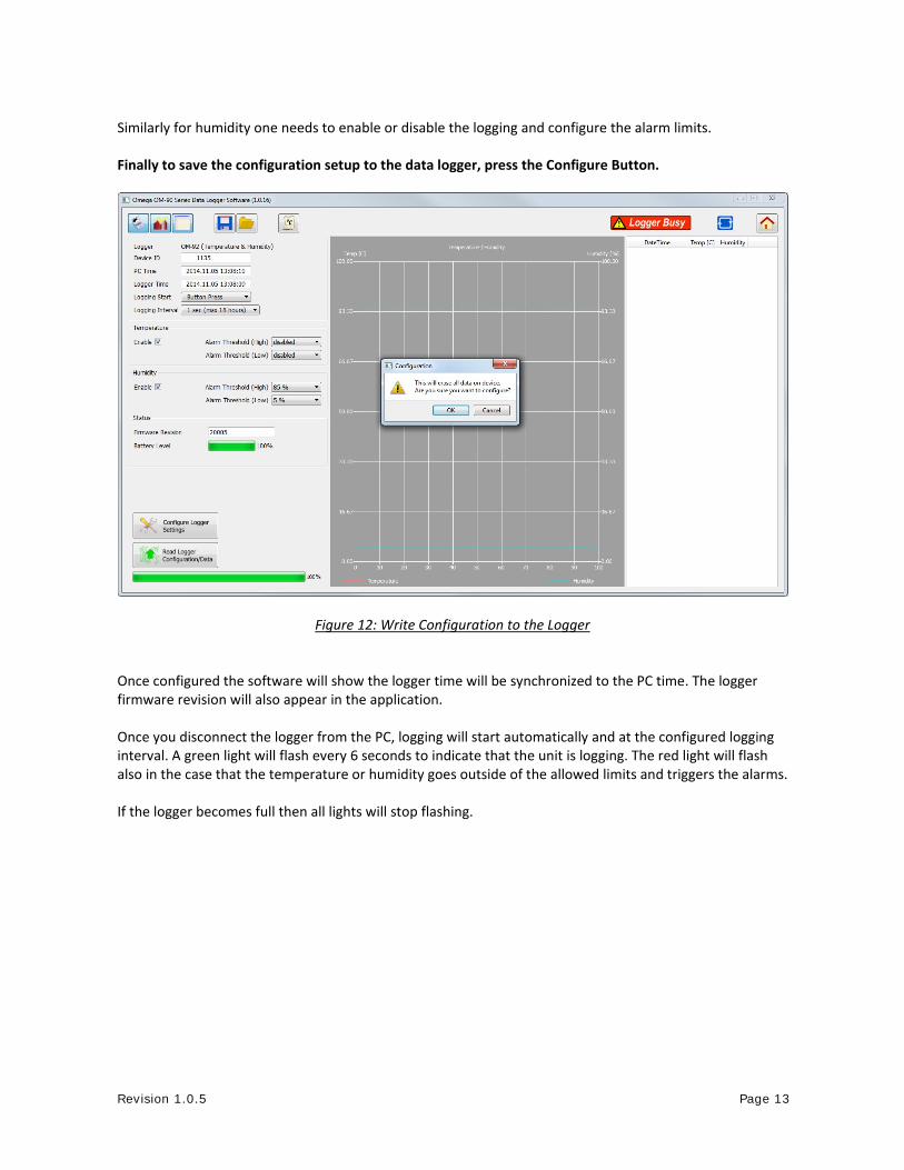
Similarly for humidity one needs to enable or disable the logging and configure the alarm limits. Finally to save the configuration setup to the data logger, press the Configure Button.
Figure 12: Write Configuration to the Logger Once configured the software will show the logger time will be synchronized to the PC time. The logger firmware revision will also appear in the application. Once you disconnect the logger from the PC, logging will start automatically and at the configured logging interval. A green light will flash every 6 seconds to indicate that the unit is logging. The red light will flash also in the case that the temperature or humidity goes outside of the allowed limits and triggers the alarms. If the logger becomes full then all lights will stop flashing.
Revision 1.0.5 Page 14
7.4. Saving a Configuration File
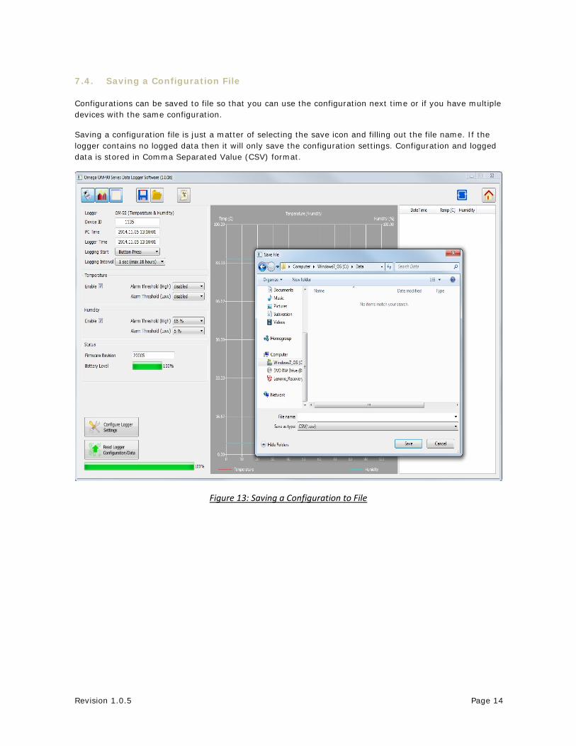
Configurations can be saved to file so that you can use the configuration next time or if you have multiple devices with the same configuration.
Saving a configuration file is just a matter of selecting the save icon and filling out the file name. If the logger contains no logged data then it will only save the configuration settings. Configuration and logged data is stored in Comma Separated Value (CSV) format.
Figure 13: Saving a Configuration to File

Revision 1.0.5 Page 15
7.5. Loading a Configuration from File
Loading a configuration file from disk is just a matter of selecting the open icon and selecting the configuration file name. This upload presents a simple way to configure multiple loggers with the same configuration. This ensures a common configuration and saves time/effort when configuring multiple devices.
Figure 14: Loading a Configuration from File
Remember to press the configuration button if you want the configuration data held in the software to be written to your data logger.

Revision 1.0.5 Page 16
7.6. Retrieving Logged Data
Data can be retrieved from the logger by connecting to the logger and then pressing the read button at the bottom left of the software.
Both the device configuration and logged data will immediately become uploaded and viewable in the configuration, graphical and spreadsheet views.
Zooming in and out of the graphs can be achieved by the following controls: To Zoom In - Drag the left mouse button To Zoom Out - Click the right mouse button When zoomed in you can move around using the key-board arrows or the mouse scroll wheel
To write data and configuration to file, press the save icon. Data and configuration is then stored in Comma Separated Value (CSV) format which can be edited by third party software such as Microsoft Excel or read back into the data logger software at a later point.
Figure 15: Saving Logged Data to File
Revision 1.0.5 Page 17
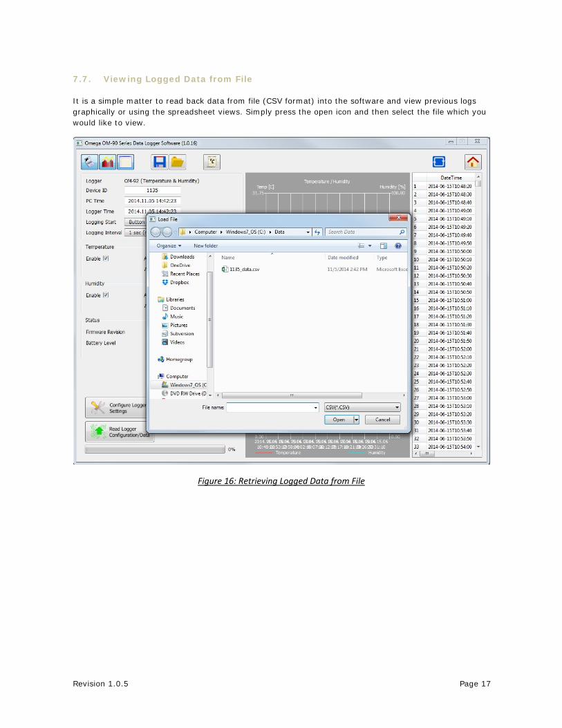
7.7. Viewing Logged Data from File
It is a simple matter to read back data from file (CSV format) into the software and view previous logs graphically or using the spreadsheet views. Simply press the open icon and then select the file which you would like to view.
Figure 16: Retrieving Logged Data from File

Revision 1.0.5 Page 18
Figure 17: Retrieving Logged Data from File (complete)
Revision 1.0.5 Page 19
7.8. Configuration of a Data Logger (Start at Specified Time)
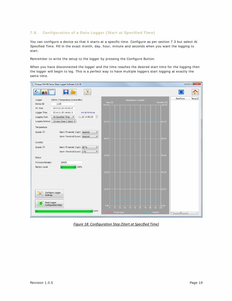
You can configure a device so that it starts at a specific time. Configure as per section 7.3 but select At Specified Time. Fill in the exact month, day, hour, minute and seconds when you want the logging to start.
Remember to write the setup to the logger by pressing the Configure Button.
When you have disconnected the logger and the time reaches the desired start time for the logging then the logger will begin to log. This is a perfect way to have multiple loggers start logging at exactly the same time.
Figure 18: Configuration Step (Start at Specified Time)

Revision 1.0.5 Page 20
7.9. Configuration of a Data Logger (Start using Button Press)
You can also configure the device so that it starts logging on a button press. Configure as per section 7.3 but select Button Press.
Remember to write the setup to the logger by pressing the Configure Button.
When you have disconnected the logger you can start logging by a simple button press. You will then see it is logging because the green light starts flashing every 6 seconds. You can also stop it using a button press – and all lights will stop flashing.
Figure 19: Configuration Step (Start using Button Press)

Revision 1.0.5 Page 21
7.10. Configuration of a Data Logger (Real Time Logging)
You may also use your data logger in Real Time Logging mode. Select the start logging to Real Time Logging with the appropriate logging interval. Next press start. You will then see the software take samples from the logger directly and display them on the table and graphs. This is a way to monitor temperature and humidity conditions directly from your PC instead of using the remote logging.
Figure 20: Configuration Step (Real Time Logging)

Revision 1.0.5 Page 22
8. Mounting Guidelines
There is no particular limitation with regard to transporting your data logger. The logger may be fastened to a transportation container or loosely packed.
It is recommended however to keep some air space around the ventilation slots on the logger or else the logger may take longer to track humidity and temperature changes.
9. Battery Replacement
Your data logger uses a CR2450 3V Lithium-Ion battery.
In order to replace the battery:
First un-mount the logger.
Next the cover needs to unscrewed and removed.
The old battery should then be removed and a new battery inserted. Please try not to touch any exposed electronics in the process.
Finally attach the cover again with screws.
10. Technical Support
For technical support questions please contact Omega at:
1-800-USA-WHEN (1-800-872-9436)
Or via email to [email protected]

OMEGA’s policy is to make running changes, not model changes, whenever an improvement is possible. This affords our customers the latest in technology and engineering.OMEGA is a registered trademark of OMEGA ENGINEERING, INC.© Copyright 2017 OMEGA ENGINEERING, INC. All rights reserved. This document may not be copied, photocopied, reproduced, translated, or reduced to any electronic medium or machine-readable form, in whole or in part, without the prior written consent of OMEGA ENGINEERING, INC.
FOR WARRANTY RETURNS, please have the following information available BEFORE contacting OMEGA:1. Purchase Order number under which the product
was PURCHASED,2. Model and serial number of the product under
warranty, and3. Repair instructions and/or specific problems relative to the product.
FOR NON-WARRANTY REPAIRS, consult OMEGA for current repair charges. Have the following information available BEFORE contacting OMEGA:1. Purchase Order number to cover the COST of the repair,2. Model and serial number of the product, and3. Repair instructions and/or specific problems relative to the product.
RETURN REQUESTS/INQUIRIESDirect all warranty and repair requests/inquiries to the OMEGA Customer Service Department. BEFORE RETURNING ANY PRODUCT(S) TO OMEGA, PURCHASER MUST OBTAIN AN AUTHORIZED RETURN (AR) NUMBER FROM OMEGA’S CUSTOMER SERVICE DEPARTMENT (IN ORDER TO AVOID PROCESSING DELAYS). The assigned AR number should then be marked on the outside of the return package and on any correspondence.The purchaser is responsible for shipping charges, freight, insurance and proper packaging to prevent breakage in transit.
WARRANTY/DISCLAIMEROMEGA ENGINEERING, INC. warrants this unit to be free of defects in materials and workmanship for a period of 13 months from date of purchase. OMEGA’s WARRANTY adds an additional one (1) month grace period to the normal one (1) year product warranty to cover handling and shipping time. This ensures that OMEGA’s customers receive maximum coverage on each product.If the unit malfunctions, it must be returned to the factory for evaluation. OMEGA’s Customer Service Department will issue an Authorized Return (AR) number immediately upon phone or written request. Upon examination by OMEGA, if the unit is found to be defective, it will be repaired or replaced at no charge. OMEGA’s WARRANTY does not apply to defects resulting from any action of the purchaser, including but not limited to mishandling, improper interfacing, operation outside of design limits, improper repair, or unauthorized modification. This WARRANTY is VOID if the unit shows evidence of having been tampered with or shows evidence of having been damaged as a result of excessive corrosion; or current, heat, moisture or vibration; improper specification; misapplication; misuse or other operating conditions outside of OMEGA’s control. Components in which wear is not warranted, include but are not limited to contact points, fuses, and triacs.OMEGA is pleased to offer suggestions on the use of its various products. However, OMEGA neither assumes responsibility for any omissions or errors nor assumes liability for any damages that result from the use of its products in accordance with information provided by OMEGA, either verbal or written. OMEGA warrants only that the parts manufactured by the company will be as specified and free of defects. OMEGA MAKES NO OTHER WARRANTIES OR REPRESENTATIONS OF ANY KIND WHATSOEVER, EXPRESSED OR IMPLIED, EXCEPT THAT OF TITLE, AND ALL IMPLIED WARRANTIES INCLUDING ANY WARRANTY OF MERCHANTABILITY AND FITNESS FOR A PARTICULAR PURPOSE ARE HEREBY DISCLAIMED. LIMITATION OF LIABILITY: The remedies of purchaser set forth herein are exclusive, and the total liability of OMEGA with respect to this order, whether based on contract, warranty, negligence, indemnification, strict liability or otherwise, shall not exceed the purchase price of the component upon which liability is based. In no event shall OMEGA be liable for consequential, incidental or special damages.CONDITIONS: Equipment sold by OMEGA is not intended to be used, nor shall it be used: (1) as a “Basic Component” under 10 CFR 21 (NRC), used in or with any nuclear installation or activity; or (2) in medical applications or used on humans. Should any Product(s) be used in or with any nuclear installation or activity, medical application, used on humans, or misused in any way, OMEGA assumes no responsibility as set forth in our basic WARRANTY/DISCLAIMER language, and, additionally, purchaser will indemnify OMEGA and hold OMEGA harmless from any liability or damage whatsoever arising out of the use of the Product(s) in such a manner.
M5440/1017
Where Do I Find Everything I Need for Process Measurement and Control?
OMEGA…Of Course!Shop online at omega.com
TEMPERATUREMU Thermocouple, RTD & Thermistor Probes, Connectors, Panels & Assemblies MU Wire: Thermocouple, RTD & ThermistorMU Calibrators & Ice Point ReferencesMU Recorders, Controllers & Process MonitorsMU Infrared Pyrometers
PRESSURE, STRAIN AND FORCEMU Transducers & Strain GagesMU Load Cells & Pressure GagesMU Displacement TransducersMU Instrumentation & Accessories
FLOW/LEVELMU Rotameters, Gas Mass Flowmeters & Flow ComputersMU Air Velocity IndicatorsMU Turbine/Paddlewheel SystemsMU Totalizers & Batch Controllers
pH/CONDUCTIVITYMU pH Electrodes, Testers & AccessoriesMU Benchtop/Laboratory MetersMU Controllers, Calibrators, Simulators & PumpsMU Industrial pH & Conductivity Equipment
DATA ACQUISITIONMU Communications-Based Acquisition SystemsMU Data Logging SystemsMU Wireless Sensors, Transmitters, & ReceiversMU Signal ConditionersMU Data Acquisition Software
HEATERSMU Heating CableMU Cartridge & Strip HeatersMU Immersion & Band HeatersMU Flexible HeatersMU Laboratory Heaters
ENVIRONMENTAL MONITORING AND CONTROLMU Metering & Control InstrumentationMU RefractometersMU Pumps & TubingMU Air, Soil & Water MonitorsMU Industrial Water & Wastewater TreatmentMU pH, Conductivity & Dissolved Oxygen Instruments