shop on line at - omega engineering · pdf filedp25-th thermistor indicator / controller...
TRANSCRIPT

DP25-THThermistor Indicator / Controller
omega.com e-mail: [email protected]
For latest product manualsomegamanual.info
User’s Guide
Shop on line at
USAMADE IN

It is the policy of OMEGA to comply with all worldwide safety and EMC/EMI regulations that apply. OMEGA is constantly pursuing certification of its products to the European NewApproach Directives. OMEGA will add the CE mark to every appropriate device upon certification.
The information contained in this document is believed to be correct, but OMEGA Engineering, Inc. accepts no liability for any errors it contains, and reserves the right to alterspecifications without notice.
WARNING: These products are not designed for use in, and should not be used for, patient-connected applications.
This device is marked with the international caution symbol. It is important to read the Setup Guide before installing or commissioning this device as the guide contains importantinformation relating to safety and EMC.
This device is marked with the international caution symbol. It is important to read the Setup Guide before installing or commissioning this device as the guide containsimportant information relating to safety and EMC.!
Servicing North America:USA: One Omega Drive, P.O. Box 4047ISO 9001 Certified Stamford CT 06907-0047 TEL: (203) 359-1660 FAX: (203) 359-7700 e-mail: [email protected]
Canada: 976 Bergar Laval (Quebec) H7L 5A1 TEL: (514) 856-6928 FAX: (514) 856-6886 e-mail: [email protected]
For immediate technical or application assistance:USA and Canada: Sales Service: 1-800-826-6342 / 1-800-TC-OMEGA®
Customer Service: 1-800-622-2378 / 1-800-622-BEST®
Engineering Service: 1-800-872-9436 / 1-800-USA-WHEN®
Mexico and TEL: (001)800-TC-OMEGA® FAX: (001) 203-359-7807 Latin America: En Español: (001) 203-359-7803 e-mail: [email protected]
Servicing Europe:Benelux: Postbus 8034, 1180 LA Amstelveen, The Netherlands TEL: +31 20 3472121 FAX: +31 20 6434643 Toll Free in Benelux: 0800 0993344 e-mail: [email protected]
Czech Republic: Frystatska 184, 733 01 Karviná TEL: +420 59 6311899 FAX: +420 59 6311114 e-mail: [email protected]
France: 11, rue Jacques Cartier, 78280 Guyancourt TEL: +33 1 61 37 29 00 FAX: +33 1 30 57 54 27 Toll Free in France: 0800 466 342
e-mail: [email protected]
Germany/Austria: Daimlerstrasse 26, D-75392 Deckenpfronn, Germany TEL: +49 7056 9398-0 FAX: +49 7056 9398-29 Toll Free in Germany: 0800 639 7678 e-mail: [email protected]
United Kingdom: One Omega DriveISO 9002 Certified River Bend Technology Centre Northbank, Irlam Manchester M44 5BD United Kingdom TEL: +44 161 777 6611 FAX: +44 161 777 6622 Toll Free in England: 0800 488 488 e-mail: [email protected]
OMEGAnet® On-Line Servicewww.omega.com
Internet [email protected]
®
®

ii
MANUAL OBJECTIVE
This manual shows you how to set up and use the thermistorindicator/controller.
Table A-1. Sections of the Manual
If you want to read about: Sec# Refer to section
Unpacking; safety considerations 1 Introduction
Meter description and features 2 About the Meter
Main board power jumpers; 3 Getting Startedpanel mounting, sensor input, main power and analog output option and dual relay output option
Input type; decimal point position; 4 Configuring the Meterreading configuration: setpoint configurations; setpoint deadbands, output configuration (analog output option); analog output option scaling, lock out configuration
Selecting Setpoint Values 5 Selecting Setpoint Values
Display messages 6 Display Messages
Meter menu/sub-menu messages 7 Menu Configuration Displays
Setpoint configuration messages 8 Setpoint Configuration Displays
Specifications 9 Specifications
Factory Defaults 10 Factory Preset ValuesSetup as Shipped

Table of Contents
ii
Table of Contents
Section Page
SEC 1 INTRODUCTION . . . . . . . . . . . . . . . . . . . . . . . . . . . . . . . . . . . . . . .11.1 Unpacking . . . . . . . . . . . . . . . . . . . . . . . . . . . . . . . . . . . . . .11.2 Safety Considerations . . . . . . . . . . . . . . . . . . . . . . . . . . . . . .2
SEC 2 ABOUT THE METER . . . . . . . . . . . . . . . . . . . . . . . . . . . . . . . . . . . .32.1 Description . . . . . . . . . . . . . . . . . . . . . . . . . . . . . . . . . . . . . .32.2 Features . . . . . . . . . . . . . . . . . . . . . . . . . . . . . . . . . . . . . . . .32.3 Available Accessories . . . . . . . . . . . . . . . . . . . . . . . . . . . . . .42.4 Front of the Meter . . . . . . . . . . . . . . . . . . . . . . . . . . . . . . . . .52.5 Front-Panel Button Lock Out . . . . . . . . . . . . . . . . . . . . . . . . .82.6 Back of the Meter . . . . . . . . . . . . . . . . . . . . . . . . . . . . . . . . .92.7 Disassembly . . . . . . . . . . . . . . . . . . . . . . . . . . . . . . . . . . . .11
SEC 3 GETTING STARTED . . . . . . . . . . . . . . . . . . . . . . . . . . . . . . . . . . .123.1 Rating/Product Label . . . . . . . . . . . . . . . . . . . . . . . . . . . . .123.2 Main Board Power Jumpers . . . . . . . . . . . . . . . . . . . . . . . .123.3 Main Board Jumpers . . . . . . . . . . . . . . . . . . . . . . . . . . . . . .143.4 Panel Mounting . . . . . . . . . . . . . . . . . . . . . . . . . . . . . . . . .153.5 Connecting Sensor Input . . . . . . . . . . . . . . . . . . . . . . . . . .163.6 Connecting Main Power . . . . . . . . . . . . . . . . . . . . . . . . . . .173.7 Connecting Analog and Relay Output Options . . . . . . . . . . .18
SEC 4 CONFIGURING THE METER . . . . . . . . . . . . . . . . . . . . . . . . . . . . .204.1 Selecting the Input Type . . . . . . . . . . . . . . . . . . . . . . . . . . .204.2 Selecting a Decimal Point Position . . . . . . . . . . . . . . . . . . .214.3 Using Reading Configuration . . . . . . . . . . . . . . . . . . . . . . .214.4 Using Setpoint 1 Configurations . . . . . . . . . . . . . . . . . . . . .224.4.1 Setting Setpoint 1's Active Band . . . . . . . . . . . . . . . . . . . . .224.4.2 Selecting if Setpoint 1 is Latched or Unlatched . . . . . . . . . .234.5 Using Setpoint 2 Configurations . . . . . . . . . . . . . . . . . . . . .234.5.1 Setting Setpoint 2's Active Band . . . . . . . . . . . . . . . . . . . . .234.5.2 Selecting if Setpoint 2 is Latched or Unlatched . . . . . . . . . .24

iii
Table of Contents
Table of Contents
Section Page
4.6 Setting the Setpoint 1 Deadband . . . . . . . . . . . . . . . . . . . .244.7 Setting the Setpoint 2 Deadband . . . . . . . . . . . . . . . . . . . .264.8 Using Output Configuration . . . . . . . . . . . . . . . . . . . . . . . . .264.8.1 Enabling or Disabling the Analog Output Option . . . . . . . . .264.8.2 Selecting the Analog Output Option
as Current or Voltage . . . . . . . . . . . . . . . . . . . . . . . . . . . . .274.9 Using Output Scale and Offset . . . . . . . . . . . . . . . . . . . . . .284.9.1 Example for Output Scale and Offset . . . . . . . . . . . . . . . . .304.10 Correcting Thermistor Temperature Offset Error . . . . . . . . .32
SEC 5 SELECTING SETPOINT VALUES . . . . . . . . . . . . . . . . . . . . . . . . .35
SEC 6 DISPLAY MESSAGES . . . . . . . . . . . . . . . . . . . . . . . . . . . . . . . . . .36
SEC 7 MENU CONFIGURATION DISPLAYS . . . . . . . . . . . . . . . . . . . . . . .37
SEC 8 SETPOINT CONFIGURATION DISPLAYS . . . . . . . . . . . . . . . . . . .40
SEC 9 SPECIFICATIONS . . . . . . . . . . . . . . . . . . . . . . . . . . . . . . . . . . . . .41
SEC 10 FACTORY PRESET VALUES . . . . . . . . . . . . . . . . . . . . . . . . . . . .45
CE APPROVAL SECTION . . . . . . . . . . . . . . . . . . . . . . . . . . . . . . . . . . . . . . . .46
Notes, Warnings and Cautions
iv
NOTES, WARNINGS and CAUTIONS
Information that is especially important to note is identified by three labels:
• NOTE• WARNING• CAUTION• IMPORTANT
NOTE: provides you with information that is important to successfully setupand use the Programmable Digital Meter.
CAUTION or WARNING: tells you about the risk of electric shock.
CAUTION, WARNING or IMPORTANT: tells you of circumstances orpractices that can effect the meter's functionality and must refer toaccompanying documents.
1
Introduction 1SECTION 1. INTRODUCTION
1.1 UNPACKING
Remove the Packing List and verify that all equipment has been received. Ifthere are any questions about the shipment, use the phone number for theCustomer Service Department nearest you.
Upon receipt of shipment, inspect the container and equipment for any signs ofdamage. Take particular note of any evidence of rough handling in transit.Immediately report any damage to the shipping agent.
The carrier will not honor any claims unless all shipping material issaved for their examination. After examining and removing contents,save packing material and carton in the event reshipment isnecessary.
Verify that you receive the following items in the shipping box:
QTY DESCRIPTION
1 Programmable Digital Meter indicator/controller with allapplicable connectors attached.
1 Owner's Manual
1 Set Mounting brackets

1 Introduction
2
1.2 SAFETY CONSIDERATIONS
This device is marked with the international caution symbol. It is important to read this manual before installing or commissioning this device as it containsimportant information relating to Safety and EMC (Electromagnetic Compatibility).
This instrument is a panel mount device protected in accordance with EN 61010-1:2001, electrical safety requirements for electrical equipment for measurement,control and laboratory. Installation of this instrument should be done by qualifiedpersonnel. In order to ensure safe operation, the following instructions should befollowed.
This instrument has no power-on switch. An external switch or circuit-breaker shallbe included in the building installation as a disconnecting device. It shall be marked toindicate this function, and it shall be in close proximity to the equipment within easyreach of the operator. The switch or circuit-breaker shall not interrupt the ProtectiveConductor (Earth wire), and it shall meet the relevant requirements of IEC 947–1 andIEC 947-3 (International Electrotechnical Commission). The switch shall not beincorporated in the main supply cord.
Furthermore, to provide protection against excessive energy being drawn from themain supply in case of a fault in the equipment, an overcurrent protection device shallbe installed.
• Do not exceed voltage rating on the label located on the top of the instrumenthousing.
• Always disconnect power before changing signal and power connections.• Do not use this instrument on a work bench without its case for safety reasons.• Do not operate this instrument in flammable or explosive atmospheres.• Do not expose this instrument to rain or moisture.• Unit mounting should allow for adequate ventilation to ensure instrument does not
exceed operating temperature rating.• Use electrical wires with adequate size to handle mechanical strain and power
requirements. Install without exposing bare wire outside the connector to minimizeelectrical shock hazards.
EMC Considerations• Whenever EMC is an issue, always use shielded cables.• Never run signal and power wires in the same conduit.• Use signal wire connections with twisted-pair cables.• Install Ferrite Bead(s) on signal wires close to the instrument if EMC problems
persist.
Failure to follow all instructions and warnings may result in injury!
Note

About The Meter 2
3
SECTION 2. ABOUT THE METER
2.1 DESCRIPTION
The thermistor indicator/controller converts the resistance of a thermistor probeto the equivalent temperature. The meter can be configured to use eight of theavailable thermistor probe types. There are four full digits to display temperaturein Fahrenheit or Celsius. Maximum and minimum temperature values areretained and can be displayed or reset with the push of a front panel button.Two optional setpoints are available to control internal form C relays for processcontrol. An optional analog output is available to send a scaled proportionalvoltage or current to a remote device. An internal mechanical lockout has beenincluded to guard against unauthorized changes.
2.2 FEATURES
Standard features:
* 4-digit 14-segment LED display* NEMA 4/Type 4 front bezel* ±0.2°C accuracy* ±0.1°C repeatability* 44004, 44005, 44006, 44007, 44008, 44016,
44018 and linear 700 thermistor types* Peak and valley detection and memory* Nonvolatile memory for configuration settings* Easy setup for proportional control* 115 or 230 Vac 50/60 Hz power supply* 0.01°C/F resolution* Front panel push button lock out
Optional features (must be ordered at time of purchase):* Dual 5 amp, form C relay outputs * Scalable analog output

2 About The Meter
4
2.3 AVAILABLE ACCESSORIES
Table 2-1. Accessories and Add-ons
Add-On Options FS Special Calib/Config
SPC4 NEMA-4 Splash Proof Cover
SPC18 NEMA-4 Splash Proof Cover, NEW
Accessories TP1A Trimplate panel adaptor. Adapts DIN1A/DIN2A cases to larger panel cutouts
RP18 19-In. Rack Panel for one (1) 1/8 DIN instrument
RP28 19-In. Rack Panel for two (2) 1/8 DIN instrument
RP38 19-In. Rack Panel for three (3) 1/8 DIN instrument
About The Meter 2
5
2.4 FRONT OF THE METER
Figure 2-1 shows the front of the meter.
Figure 2-1. Front-Panel Illustration
METER DISPLAY:
Digital LED display - 1.9.9.9. or 9.9.9.9. 4-digit 14 segment, 0.54" high LED display with programmable decimal point.
These meter display windows light when appropriate (setpoints 1 and 2 lightonly if your meter has dual relay output capabilities):
1 Setpoint 1 status 2 Setpoint 2 status
°C Celsius°F Fahrenheit
2 About The Meter
6
2.4 FRONT OF THE METER (Continued)
METER BUTTONS
SETPTS BUTTON - If your meter does not have dual relay output capabilities,pressing this button displays "RUN" and goes back to the run mode.
If your meter has dual relay output capabilities, this button will sequentially recall(in the run mode) the previous setpoint settings. As necessary, use the /MAXand /MIN buttons to alter these settings, then press the SETPTS button tostore new values. Unless you press the SETPTS, /MIN, or /MAX buttonwithin 20 seconds, the meter will scroll to setpoint 2 and then to the run mode.
/MAX BUTTON - In the run mode, this button will recall the PEAK readingsince the last press of the RESET button.
In the configuration mode, press this button to change the value of the flashingdigit shown on the display and/or toggle between menu choices, such as "R.1=F"or "R.1=C". When configuring your setpoint values, press the /MAX button toadvance the flashing digit's value from 0 to 9 by 1.
/MIN BUTTON - In the run mode, press this button to recall the valley readingsince the last press of the RESET button.
In the configuration mode, press this button to scroll to the next digit.

About The Meter 2
7
2.4 FRONT OF THE METER (Continued)
MENU BUTTON - In the run mode, press the MENU button to terminate thecurrent measuring process and enter you into the configuration mode.
In the configuration mode, press the MENU button to store changes in thenonvolatile memory and advance you to the next menu item.
RESET BUTTON - In the setpoint mode, press the RESET button to enter therun mode. The meter shows "RUN" and returns to the run mode.
In the configuration mode, press the RESET button to review the previousmenu. Press the RESET button twice to perform a hard reset. The metershows "RST", followed by "INIT", then enters the run mode.
In the peak mode, press the RESET button to reset peak value. The metershows "PK.RS" and returns to the run mode.
In the valley mode, press the RESET button to reset valley value. The metershows "VL.RS" and returns to the run mode.
In the run mode, if your meter does not have dual relay output capabilities,pressing the RESET button shows "RUN" and goes back to the run mode. Ifyour meter has dual relay output capabilities, press the RESET button (in therun mode) to reset the latched setpoints. The meter shows "SP.RS" andreturns to the run mode.
When in setpoint or configuration mode, if the meter shows 9999 or -1999 with all flashing digits, the value has overflowed. Press the /MAX button to start a new value.

2 About The Meter
8
2.5 FRONT-PANEL BUTTON LOCK OUT (For Security Purposes)
2.5.1 Jumper Lock Out
To lock all front-panel buttons, remove the S3-A jumper (refer to Figure 3-2).
To lock the MENU button only, verify that the S3-B jumper is removed, theninstall the S3-A and S3-E jumpers (refer to Table 3-1). If you press the MENUbutton, the meter shows "LOCK" and returns to the run mode.
2.5.2 Push Button Lock Out
To lock the RESET, MENU and SETPTS buttons, verify that the S3-A jumperis installed and the S3-E jumper is not installed, then follow these steps:
In the run mode -
1. Press and hold down RESET button. The meter shows "SP.RS" or "RUN".Do not release the RESET button.
2. Press the MENU button and hold RESET button down (3 - 5 seconds) untilthe meter shows "LOCK".
3. Release both buttons.
To unlock the RESET, MENU and SETPTS buttons, follow these steps:
1. Press and hold down RESET button. The meter shows "LOCK". Do notrelease the RESET button.
2. Press the MENU button and hold RESET button down (3 - 5 seconds) untilthe meter shows "UN.LK" .
3. Release both buttons.

About The Meter 2
9
2.5 BACK OF THE METER
Figure 2-2 shows the label describing the connectors on the back of the meter.Table 2-2 on the following page gives a brief description of each connector at theback of the meter.
Figure 2-2. Connectors
+S
TH INPUT*ANALOG OUT*
TB1RELAY 1 RELAY 2
ISOLATED*
* = CONNECT TO LOW VOLTAGE LIMITED ENERGY CIRCUITRY ONLY.
ANALOG OUT
TB2
RTNVOLT CURR
TB5POWER & INPUT CONNECTIONS (THERMISTOR)
DC
TB1
AC
987
N/C + -
N.C.2N.C.1N.O.1 COM1 COM2N.O.2
VOLT RTNCURR +R-SL N
dc-power connectorlabel detail
321 654
987 12*11*10* 3*2*1*
3*2*1*

2 About The Meter
10
2.6 BACK OF THE METER (Continued)
Table 2-2. Connector Description
Connector Description
TB1-1 Setpoint 1: Normally open (N.O.1) connection.
TB1-2 Setpoint 1: Normally closed (N.C.1) connection.
TB1-3 Setpoint 1: Common 1 connection
TB1-4 Setpoint 2: Normally open (N.O.2) connection.
TB1-5 Setpoint 2: Normally closed (N.C.2) connection.
TB1-6 Setpoint 2: Common 2 connection
TB1-7 ac line connection (no connection on dc powered units)
TB1-8 ac neutral connection (+ Input on dc powered units)
TB1-9 ac ground (dc power return on dc powered units)
TB1-10 Analog 1 voltage output
TB1-11 Analog 2 current output
TB1-12 Analog 3 return
TB2-1 +S Thermistor input
TB2-2 -S Thermistor input
TB2-3 +R 3rd input for Linear Thermistor
TB5-1 Isolated Analog Voltage Output
TB5-2 Isolated Analog Current Output
TB5-3 Isolated Analog Output Return

About The Meter 2
11
2.7 DISASSEMBLY
You may need to open up the meter for one of the following reasons:• To check or change the 115 or 230 Vac power jumpers.
• To install or remove jumpers on the main board.
Disconnect the power supply before proceeding.
To remove and access the main board, follow these steps:
• Disconnect the main power from the meter.
• Remove the back case cover.
• Lift the back of the main board upwards and let it slide out of thecase.

3 Getting Started
12
SECTION 3. GETTING STARTED
Caution: The meter has no power-on switch, so it will be in operation assoon you apply power.
If you power off/on the meter, it displays “RST”, followed by a scrolling display of“THERMISTOR”, followed by “Vxx” (designating the version number, xx stands for thecurrent version). Write down this version number as you will need if if you telephoneCustomer Service.
3.1 RATING/PRODUCT LABELThis label is located on top of the meter housing (refer to Figure 3-4).
3.2 MAIN BOARD POWER JUMPERS (Refer to Figure 3-1)
Important: If you want to change the Factory preset jumpers, do thefollowing steps; otherwise go to section 3.3.
Disconnect the power from the unit before proceeding.
1. Remove the main board from the case. Refer to Section 2.7.
2. Locate the solder jumpers W1, W2, and W3 (located near the edge of the mainboard alongside the transformer).
3. If your power requirement is 115 Vac, solder jumpers W1 and W3 should bewired, but jumper W2 should not. If your power requirement is 230 Vac,solder jumper W2 should be wired, but jumpers W1 and W3 should not.
Figure 3-1 shows the location of solder jumpers W1 through W3.
Figure 3.1 Main Board Power Jumpers (W1, W2, W3)
DIS
PLA
Y B
OA
RD
TRANSFORMERW3 W1
W2
115V ac
230V ac
W3 W2 W1
Getting Started 3
13
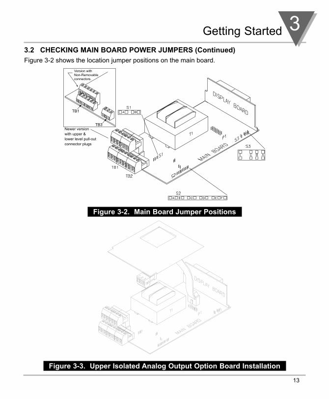
3.2 CHECKING MAIN BOARD POWER JUMPERS (Continued)Figure 3-2 shows the location jumper positions on the main board.
Figure 3-2. Main Board Jumper Positions
Figure 3-3. Upper Isolated Analog Output Option Board Installation
Newer versionwith upper &lower level pull-outconnector plugs
TB1
TB3
Version with Non-Removable connectors.

3 Getting Started
14
3.3 MAIN BOARD JUMPERS
S2 jumpers and TP1 through TP6 (test posts) are used for calibration purposesonly. Do not change.
S3 jumpers are used for the following (refer to Figure 3-2):
* To enable or disable the front panel push-buttons* To allow for an extremely low resistance load for analog output * To disable the MENU button* To perform calibration procedure
Table 3-1. S3 Jumper Functions
Jumper Description
S3-A Install to enable front panel push-buttons. Remove to disable all front panel push-buttons
S3-B Removed. Install for meter calibration.
S3-C Normally removed. Install for analog voltage outputwhen load has less than 1 KΩ impedance. Careshould be taken when installing this jumper, as thereis the possibility of oscillation.
S3-E If installed without S3-B, the MENU button locks out.If you press the MENU button, the meter shows"LOCK".
Getting Started 3
15
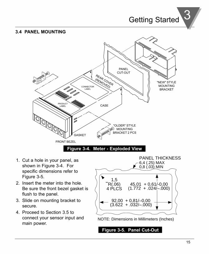
3.4 PANEL MOUNTING
Figure 3-4. Meter - Exploded View
1. Cut a hole in your panel, asshown in Figure 3-4. Forspecific dimensions refer toFigure 3-5.
2. Insert the meter into the hole. Be sure the front bezel gasket isflush to the panel.
3. Slide on mounting bracket tosecure.
4. Proceed to Section 3.5 toconnect your sensor input andmain power.
Figure 3-5. Panel Cut-Out
"NEW" STYLEMOUNTINGBRACKET
FRONT BEZEL
CASE
REAR COVER
(REMOVED)
PANELCUT-OUT
"OLDER" STYLEMOUNTING
BRACKET 2 PCSGASKET
PRODUCTLABEL
CONNECTORLABEL
45,01 + 0,61/-0,00(1.772 + .024/–.000)
92,00 + 0,81/–0,00(3.622 + .032/–.000)
PANEL THICKNESS
1,5R(.06)
4 PLCS
6,4 (.25) MAX0,8 (.03) MIN
NOTE: Dimensions in Millimeters (Inches)
3 Getting Started
16
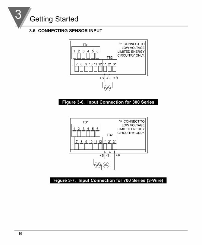
3.5 CONNECTING SENSOR INPUT
Figure 3-6. Input Connection for 300 Series
Figure 3-7. Input Connection for 700 Series (3-Wire)
TB1
TB2
1 2 3 4 5 6
7 8 9 10 1* 2* 3*11 12
CONNECT TOLOW VOLTAGE
LIMITED ENERGYCIRCUITRY ONLY.
+S -S +R
*=
TB1
TB2
1 2 3 4 5 6
7 8 9 10 1* 2* 3*11 12
CONNECT TOLOW VOLTAGE
LIMITED ENERGYCIRCUITRY ONLY.
+S -S +R
*=

Getting Started 3
17
3.6 CONNECTING MAIN POWER
Connect the ac main power connections as shown in Figure 3-8.
WARNING: Do not connect ac power to your meter until you havecompleted all input and output connections. Failure to do so may result ininjury!
Figure 3-8. Main Power Connections (AC)
Table 3-2 shows the wire color and respective terminal connections for bothUSA and Europe.
Table 3-2. Power Connections
WIRE COLORS
TB1 AC POWER EUROPE USA
7 ~ ac Line Brown Black
8 ~ ac Neutral Blue White
9 ~ ac Earth Green/Yellow Green
TB1
TB2
1 2 3 4 5 6
7 8 9 10 1 2 311 12
FUSE
EARTH GROUNDGREEN WIRE
AC Power
Check for proper Earth grounding in the power distribution system (single phase).
SWITCH
LINENEUTRAL
EARTH (L) LINE
(N) NEUTRAL

3 Getting Started
18
3.6 CONNECTING MAIN POWER (Continued)
Connect the DC main power connections as shown in Figure 3-9.
Figure 3-9. Main Power Connections (DC)
3.7 CONNECTING ANALOG AND RELAY OUTPUT OPTIONS
If applicable, connect your analog and dual relay outputs at the back of themeter as shown in Figures 3-10 and 3-11.
Figure 3-10. Relay Output Connections
Relay 1 Relay 2
N.O
.1
N.C
.1
CO
M1
N.O
.2
N.C
.2
CO
M2
TB1
1 2 3 4 5 6
7 8 9 10 11 12
TB2
1 2 3
EXTERNAL LOADN
LFUSE
NO2
COM2
+ DC - DC
DC POWER
TB1
1 2 3 4 5 6
7 8 9 10 1 2 311 12
TB2
If experiencing EMC problems,connect the power supply toearth ground.

Getting Started 3
19
3.7 CONNECTING ANALOG AND RELAY OUTPUT OPTIONS (Continued)
Figure 3-11. Analog Output Connections
Figure 3-12. Isolated Analog Output Connections
0-10VDC
0-20mA
4-20mA
OR
1* 2* 3*
TB5TB1
TB21 2 3 4
1 2 3
5 6
7 8 9 10 11 12
* = CONNECT TO LOW VOLTAGE LIMITED ENERGY CIRCUITRY ONLY.
ANALOGVOLTAGE
+
-
+
-
0-10V dc
ANALOGCURRENT
0-20mAor
4-20mA
ANALOGRTN
TB1
TB2
1 2 3 4 5 6
7 8 9 10* 1 2 311*12*
*^ = CONNECT TO LOW VOLTAGE^ LIMITED ENERGY CIRCUITRY ONLY.
4 Configuring The Meter
20
SECTION 4. CONFIGURING THE METER
Read this section for step-by-step procedures on configuring your meter. Somemenu items do not display if your meter does not have analog output or dual relayoutput capabilities. These menu items are noted accordingly in the followingsubsections.
Factory defaults are in bold and italics.
Refer to Table 7-1 for a summary list of menu configurations.
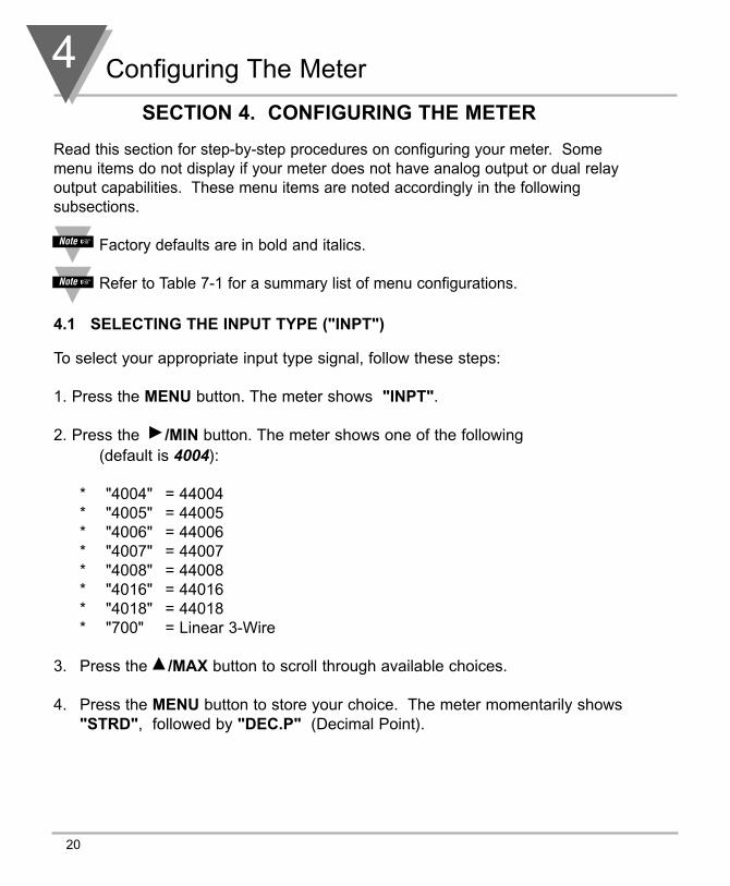
4.1 SELECTING THE INPUT TYPE ("INPT")
To select your appropriate input type signal, follow these steps:
1. Press the MENU button. The meter shows "INPT".
2. Press the /MIN button. The meter shows one of the following(default is 4004):
* "4004" = 44004 * "4005" = 44005 * "4006" = 44006 * "4007" = 44007 * "4008" = 44008 * "4016" = 44016* "4018" = 44018* "700" = Linear 3-Wire
3. Press the /MAX button to scroll through available choices.
4. Press the MENU button to store your choice. The meter momentarily shows"STRD", followed by "DEC.P" (Decimal Point).

Configuring The Meter 4
21
4.2 SELECTING A DECIMAL POINT POSITION ("DEC.P")
To select a decimal point display position, follow these steps:
1. Press the MENU button until the meter shows "DEC.P".
2. Press the /MIN button. The meter shows one of the following:
* " FFFF. " - default* "FFF.F* "FF.FF"
3. Press the /MAX button to scroll between available choices.
4. Press the MENU button to store your choice. The meter momentarily shows"STRD", followed by "RD.CF" (Reading Configuration).
When you change the decimal position the meter adjusts setpoint values andsetpoint deadbands. These adjustments are made according to the newdecimal point. If one or more of these values overflow, the meter flashes "ER2"when you store new decimal point position value.
4.3 USING READING CONFIGURATION ("RD.CF")
To select if the meter shows in Fahrenheit or Celsius, follow these steps:
1. Press the MENU button until the meter shows "RD.CF".
2. Press the /MIN button. The meter shows one of the following:
* " R.1=F " Fahrenheit - default* "R.1=C" Celsius
4 Configuring The Meter
22
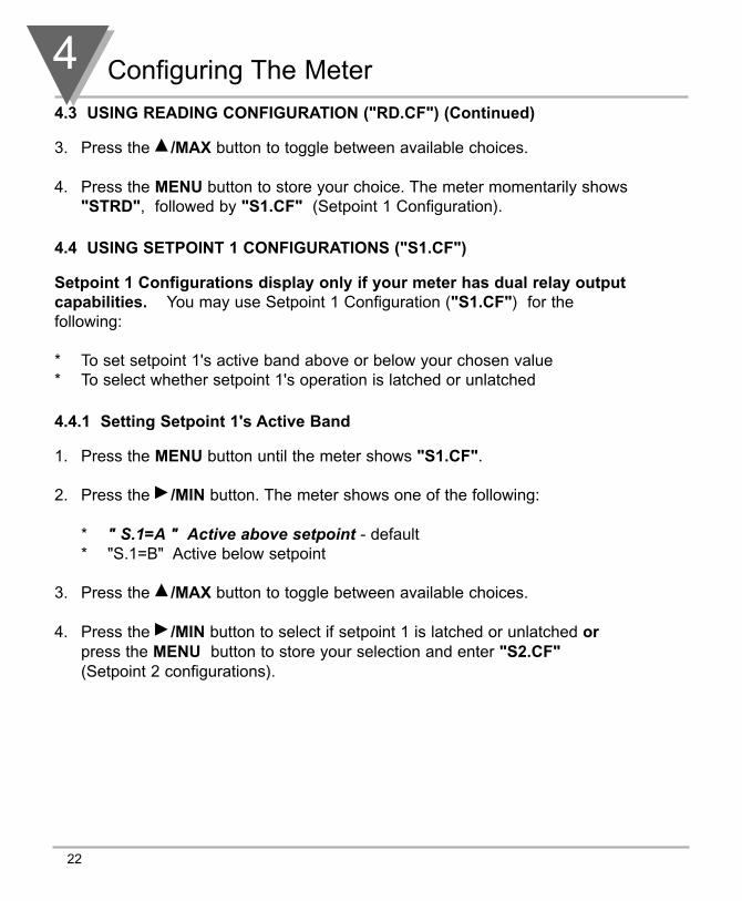
4.3 USING READING CONFIGURATION ("RD.CF") (Continued)
3. Press the /MAX button to toggle between available choices.
4. Press the MENU button to store your choice. The meter momentarily shows"STRD", followed by "S1.CF" (Setpoint 1 Configuration).
4.4 USING SETPOINT 1 CONFIGURATIONS ("S1.CF")
Setpoint 1 Configurations display only if your meter has dual relay outputcapabilities. You may use Setpoint 1 Configuration ("S1.CF") for thefollowing:
* To set setpoint 1's active band above or below your chosen value* To select whether setpoint 1's operation is latched or unlatched
4.4.1 Setting Setpoint 1's Active Band
1. Press the MENU button until the meter shows "S1.CF".
2. Press the /MIN button. The meter shows one of the following:
* " S.1=A " Active above setpoint - default * "S.1=B" Active below setpoint
3. Press the /MAX button to toggle between available choices.
4. Press the /MIN button to select if setpoint 1 is latched or unlatched orpress the MENU button to store your selection and enter "S2.CF"(Setpoint 2 configurations).

Configuring The Meter 4
23
4.4.2 Selecting if Setpoint 1 is Latched or Unlatched
1. Press the /MIN button. The meter shows one of the following:
* "S.2=L" Setpoint 1 to be latched* " S.2=U " Setpoint 1 to be unlatched - default
2. Press the /MAX button to toggle between available choices.
3. Press the MENU button to store your choice(s). The meter momentarilyshows "STRD", followed by "S2.CF" (Setpoint 2 Configuration).
4.5 USING SETPOINT 2 CONFIGURATIONS ("S2.CF")
Setpoint 2 Configurations display only if your meter has dual relay outputcapabilities. You may use Setpoint 2 Configuration ("S2.CF") for thefollowing:
* To set setpoint 2's active band above or below your chosen value* To select whether setpoint 2's operation is latched or unlatched
4.5.1 Setting Setpoint 2's Active Band
1. Press the MENU button until the meter shows "S2.CF".
2. Press the /MIN button. The meter shows one of the following:
* " S.1=A " Active above the setpoint - default* "S.1=B" Active below the setpoint
3. Press the /MAX button to toggle between available choices.
4. Press the /MIN button to select if setpoint 1 is latched or unlatched orpress the MENU button to store your selection and enter "S1.DB"(Setpoint 1 Deadband).

4 Configuring The Meter
24
4.5.2 Selecting if Setpoint 2 is Latched or Unlatched
1. Press the /MIN button. The meter shows one of the following:
* "S.2=L" Setpoint 1 to be latched * " S.2=U " Setpoint 1 to be unlatched - default
2. Press the /MAX button to toggle between available choices.
3. Press the MENU button to store your selection(s). The meter momentarilyshows "STRD", followed by "S1.DB" (Setpoint 1 Deadband).
4.6 SETTING THE SETPOINT 1 DEADBAND ("S1.DB")
Setpoint 1 Deadband displays only if your meter has dual relay outputcapabilities. Factory default deadband is 003. To change the deadband(hysteresis) of setpoint 1, follow these steps:
1. Press the MENU button until the meter shows "S1.DB".
2. Press the /MIN button. The meter shows the last stored number (0000through 9999) with flashing 4th digit.
3. Press the /MAX button to change the value of the flashing digit. If youcontinue to press the /MAX button, the flashing digit's value continues tochange.
4. Press the /MIN button to scroll to the next digit.
5. Press the MENU button to store your selection. The meter momentarilyshows "STRD" , followed by "S2.DB" (Setpoint 2 Deadband).

Configuring The Meter 4
25
Figure 4-1. Relay Output Triggering Example
To reset latched alarms you must:
1. Input a signal “OUT” of the Relay Triggering zone
2. Then press SETPTS and then, RESET button
SIGNALLEVEL
SIGNALLEVEL
SIGNALLEVEL
ON ONOFF
ON
ON ON ON ON ON
ON
ON
ON
OFF
OFF
ONOFF OFF
OFF OFF
ACTIVE BELOW ACTIVE ABOVE
ACTIVE BELOWWITH DEADBAND 3
ACTIVE ABOVEWITH DEADBAND 3
ACTIVE BELOW LATCHED ACTIVE ABOVE LATCHED
SETPOINT
SETPOINT
SETPOINT
NOTE: DEADBAND WORKS AS HYSTERISIS
3
3
DEADBAND
4 Configuring The Meter
26
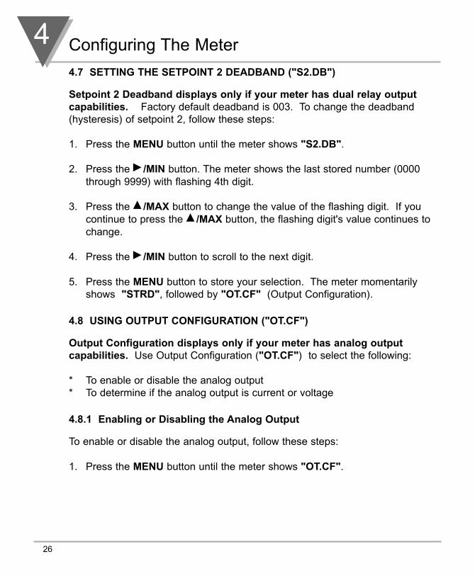
4.7 SETTING THE SETPOINT 2 DEADBAND ("S2.DB")
Setpoint 2 Deadband displays only if your meter has dual relay outputcapabilities. Factory default deadband is 003. To change the deadband(hysteresis) of setpoint 2, follow these steps:
1. Press the MENU button until the meter shows "S2.DB".
2. Press the /MIN button. The meter shows the last stored number (0000through 9999) with flashing 4th digit.
3. Press the /MAX button to change the value of the flashing digit. If youcontinue to press the /MAX button, the flashing digit's value continues tochange.
4. Press the /MIN button to scroll to the next digit.
5. Press the MENU button to store your selection. The meter momentarilyshows "STRD", followed by "OT.CF" (Output Configuration).
4.8 USING OUTPUT CONFIGURATION ("OT.CF")
Output Configuration displays only if your meter has analog outputcapabilities. Use Output Configuration ("OT.CF") to select the following:
* To enable or disable the analog output * To determine if the analog output is current or voltage
4.8.1 Enabling or Disabling the Analog Output
To enable or disable the analog output, follow these steps:
1. Press the MENU button until the meter shows "OT.CF".

Configuring The Meter 4
27
4.8.1 Enabling or Disabling the Analog Output (Continued)
2. Press the /MIN button. The meter shows one of the following: * "O.1=D" Analog output disabled* " O.1=E " Analog output enabled - default
3. Press the /MAX button to toggle between available choices.
4. Press the /MIN button to select the analog output as current/voltage orpress the MENU button to store your selection (the meter momentarilyshows "STRD" , followed by "OT.S.O", Output Scale and Offset - refer toSection 4.11).
4.8.2 Selecting the Analog Output as Current or Voltage
Remember that Output Configuration displays only if your meter has analogoutput capabilities.
1. Press the /MIN button. The meter shows one of the following: * "O.2=V" Analog output = voltage* " O.2=C " Analog output = current - default
2. Press the /MAX button to toggle between available choices.
3. Press the /MIN button to go back to selecting analog output as enabled ordisabled or press the MENU button to store your choices (the metermomentarily shows "STRD" , followed by "OT.S.O", Output Scale andOffset).
4 Configuring The Meter
28
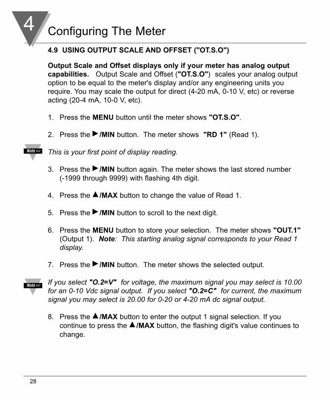
4.9 USING OUTPUT SCALE AND OFFSET ("OT.S.O")
Output Scale and Offset displays only if your meter has analog outputcapabilities. Output Scale and Offset ("OT.S.O") scales your analog outputoption to be equal to the meter's display and/or any engineering units yourequire. You may scale the output for direct (4-20 mA, 0-10 V, etc) or reverseacting (20-4 mA, 10-0 V, etc).
1. Press the MENU button until the meter shows "OT.S.O".
2. Press the /MIN button. The meter shows "RD 1" (Read 1).
This is your first point of display reading.
3. Press the /MIN button again. The meter shows the last stored number (-1999 through 9999) with flashing 4th digit.
4. Press the /MAX button to change the value of Read 1.
5. Press the /MIN button to scroll to the next digit.
6. Press the MENU button to store your selection. The meter shows "OUT.1"(Output 1). Note: This starting analog signal corresponds to your Read 1display.
7. Press the /MIN button. The meter shows the selected output.
If you select "O.2=V" for voltage, the maximum signal you may select is 10.00for an 0-10 Vdc signal output. If you select "O.2=C" for current, the maximumsignal you may select is 20.00 for 0-20 or 4-20 mA dc signal output.
8. Press the /MAX button to enter the output 1 signal selection. If youcontinue to press the /MAX button, the flashing digit's value continues tochange.

Configuring The Meter 4
29
4.9 USING OUTPUT SCALE AND OFFSET ("OT.S.O") (Continued)
9. Press the /MIN button to scroll to the next digit.
10. Press the MENU button to store your selection. The meter shows "RD 2"(Read 2). Note: This is your second point of display reading.
11. Press the /MIN button. The meter shows the last stored number (-1999 through 9999) with flashing 4th digit.
12. Press the /MAX button to change the value of the flashing digit. If youcontinue to press the /MAX button, the flashing digit's value continues tochange.
13. Press the /MIN button to scroll to the next digit.
14. Press the MENU button to store your selection. The meter shows "OUT.2"(Output 2). Note: This analog signal should correspond to your Read 2display.
15. Press the /MIN button. The meter shows the selected output.
If you select "O.2=V" for voltage, the maximum signal you may selectis 10.00 for an 0-10 Vdc signal output. If you select "O.2=C" forcurrent, the maximum signal you may select is 20.00 for a 0-20 or 4-20mA dc signal output.
4 Configuring The Meter
30
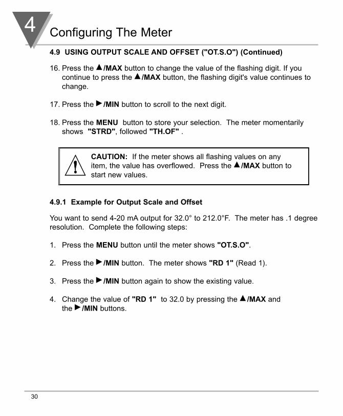
4.9 USING OUTPUT SCALE AND OFFSET ("OT.S.O") (Continued)
16. Press the /MAX button to change the value of the flashing digit. If youcontinue to press the /MAX button, the flashing digit's value continues tochange.
17. Press the /MIN button to scroll to the next digit.
18. Press the MENU button to store your selection. The meter momentarilyshows "STRD", followed "TH.OF" .
4.9.1 Example for Output Scale and Offset
You want to send 4-20 mA output for 32.0° to 212.0°F. The meter has .1 degreeresolution. Complete the following steps:
1. Press the MENU button until the meter shows "OT.S.O".
2. Press the /MIN button. The meter shows "RD 1" (Read 1).
3. Press the /MIN button again to show the existing value.
4. Change the value of "RD 1" to 32.0 by pressing the /MAX andthe /MIN buttons.
CAUTION: If the meter shows all flashing values on anyitem, the value has overflowed. Press the /MAX button tostart new values.
Configuring The Meter 4
31
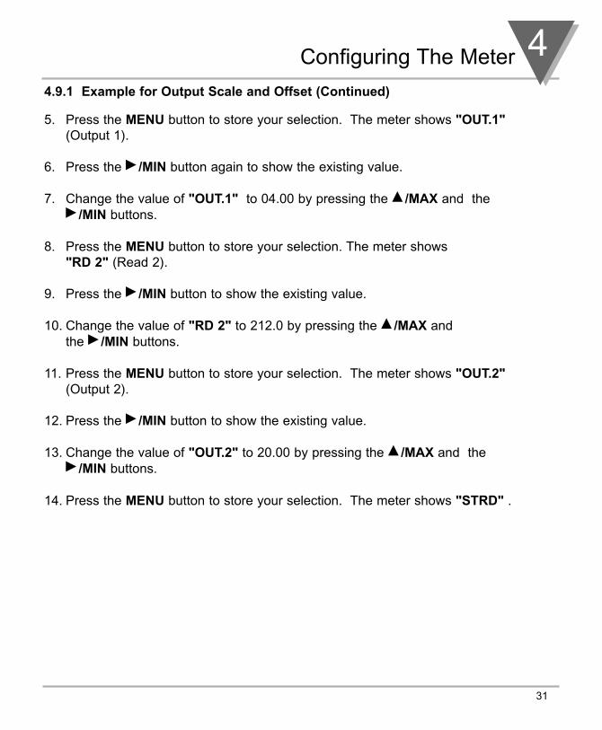
4.9.1 Example for Output Scale and Offset (Continued)
5. Press the MENU button to store your selection. The meter shows "OUT.1"(Output 1).
6. Press the /MIN button again to show the existing value.
7. Change the value of "OUT.1" to 04.00 by pressing the /MAX and the /MIN buttons.
8. Press the MENU button to store your selection. The meter shows "RD 2" (Read 2).
9. Press the /MIN button to show the existing value.
10. Change the value of "RD 2" to 212.0 by pressing the /MAX and the /MIN buttons.
11. Press the MENU button to store your selection. The meter shows "OUT.2"(Output 2).
12. Press the /MIN button to show the existing value.
13. Change the value of "OUT.2" to 20.00 by pressing the /MAX and the /MIN buttons.
14. Press the MENU button to store your selection. The meter shows "STRD" .
4 Configuring The Meter
32
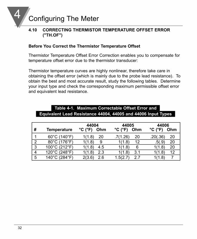
4.10 CORRECTING THERMISTOR TEMPERATURE OFFSET ERROR("TH.OF")
Before You Correct the Thermistor Temperature Offset
Thermistor Temperature Offset Error Correction enables you to compensate fortemperature offset error due to the thermistor transducer:
Thermistor temperature curves are highly nonlinear, therefore take care inobtaining the offset error (which is mainly due to the probe lead resistance). Toobtain the best and most accurate result, study the following tables. Determineyour input type and check the corresponding maximum permissible offset errorand equivalent lead resistance.
Table 4-1. Maximum Correctable Offset Error and Equivalent Lead Resistance 44004, 44005 and 44006 Input Types
1 60°C (140°F) 1(1.8) 20 .7(1.26) 20 .20(.36) 202 80°C (176°F) 1(1.8) 9 1(1.8) 12 .5(.9) 203 100°C (212°F) 1(1.8) 4.5 1(1.8) 6 1(1.8) 204 120°C (248°F) 1(1.8) 2.3 1(1.8) 3.1 1(1.8) 125 140°C (284°F) 2(3.6) 2.6 1.5(2.7) 2.7 1(1.8) 7
44004 44005 44006# Temperature °C (°F) Ohm °C (°F) Ohm °C (°F) Ohm

Configuring The Meter 4
33
4.10 CORRECTING THERMISTOR TEMPERATURE OFFSET ERROR("TH.OF") (Continued)
Table 4-2. Maximum Permissable Offset Error and Equivalent Lead Resistance 44007, 44008 and 44016 Input Types
1 60°C (140°F) .5(.9) 20 - - .2(.36) 202 80°C (176°F) 1(1.8) 20 .2(.36) 20 .5(.9) 203 100°C (212°F) 1(1.8) 10 .3(.54) 20 1(1.8) 204 120°C (248°F) 1(1.8) 5 .6(1.0) 20 1(1.8) 105 140°C (284°F) 1(1.8) 2.9 1(1.8) 17 1(1.8) 6
Table 4-3. Maximum Permissable Offset Error and Equivalent Lead Resistance 44018 Input Types
44007 44008 44016# Temperature °C (°F) Ohm °C (°F) Ohm °C (°F) Ohm
1 60°C (140°F) - -2 80°C (176°F) 1(1.8) 1473 100°C (212°F) 1(1.8) 884 120°C (248°F) - -5 140°C (284°F) - -
44018/700# Temperature °C (°F) Ohm

4 Configuring The Meter
34
4.10 CORRECTING THERMISTOR TEMPERATURE OFFSET ERROR("TH.OF") (Continued)
The following steps enable you to calibrate for the offset.
1. Press the MENU button until the meter shows "TH.OF" .
2. Press the /MIN button. The meter will show the previous offset value (4thdigit flashes).
3. Press the /MIN button again. The meter will show the readingtemperature (no digits flash).
4. a. If the value is correct, press the MENU button. The meter willshow "STRD" and 0 value will be entered at the offset.
b. If the value is not correct, enter the actual temperature using the /MAX and the /MIN buttons.
5. Press the MENU button to store new reading temperature.
NOTE 1: Select a higher temperature for a more accurate result.
NOTE 2: If values are greater than the maximum correctable offset errorthe meter will flash “ER” and will not store the new values.
NOTE 3: Temperature unit is either Celsius or Fahrenheit and alwaysdisplays at 0.01 degree resolution and automatically changes to.1 degree resolution if necessary.
Selecting Setpoint Values 5
35
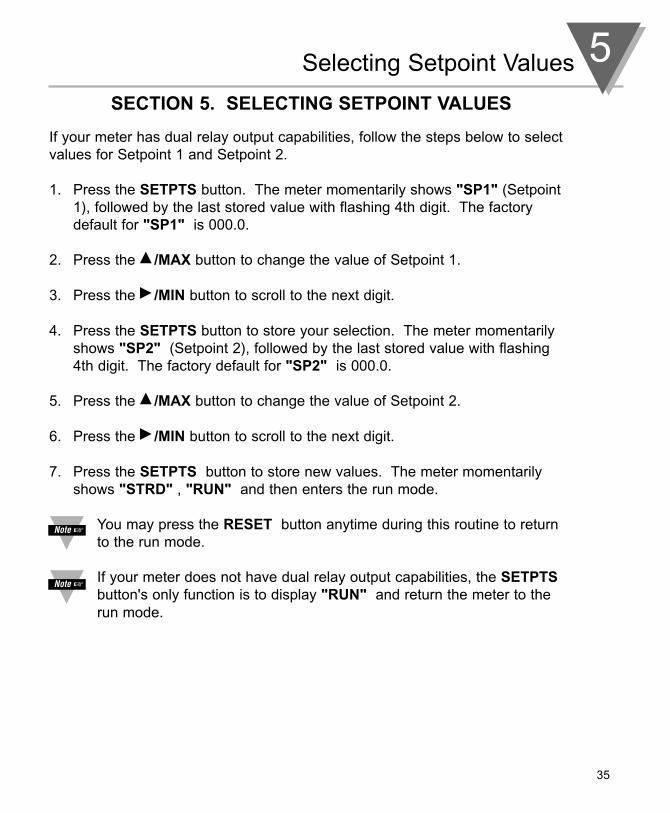
SECTION 5. SELECTING SETPOINT VALUES
If your meter has dual relay output capabilities, follow the steps below to selectvalues for Setpoint 1 and Setpoint 2.
1. Press the SETPTS button. The meter momentarily shows "SP1" (Setpoint1), followed by the last stored value with flashing 4th digit. The factorydefault for "SP1" is 000.0.
2. Press the /MAX button to change the value of Setpoint 1.
3. Press the /MIN button to scroll to the next digit.
4. Press the SETPTS button to store your selection. The meter momentarilyshows "SP2" (Setpoint 2), followed by the last stored value with flashing4th digit. The factory default for "SP2" is 000.0.
5. Press the /MAX button to change the value of Setpoint 2.
6. Press the /MIN button to scroll to the next digit.
7. Press the SETPTS button to store new values. The meter momentarilyshows "STRD" , "RUN" and then enters the run mode.
You may press the RESET button anytime during this routine to returnto the run mode.
If your meter does not have dual relay output capabilities, the SETPTSbutton's only function is to display "RUN" and return the meter to therun mode.

6 Display Messages
36
SECTION 6. DISPLAY MESSAGES
Table 6-1. Display Messages
MESSAGE DESCRIPTION
THERMISTOR Thermistor meter
RST Hard (power on) reset
INPT Input type
DEC.P Decimal point
RD.CF Reading configuration
S1.CF Setpoint 1 configuration
S2.CF Setpoint 2 configuration
S1.DB Setpoint 1 deadband
S2.DB Setpoint 2 deadband
OT.CF Output configuration
OT.S.O Output scale and offset
TH.OF Thermistor Temperature Offset Error Correction
±OPN Sensor break or temperature outside range
9999 Value overflow in setpoint/menu peak deviation routines
-1999 Value overflow in setpoint/menu peak deviation routine
ER1 2 coordinate format programming error
PEAK Peak value
VALY Valley value
PK.RS Peak reset
SP.RS Reset setpoints
SP1 Setpoint 1 value
SP2 Setpoint 2 value
ER2 One or more of these items have overflowed due todecimal point change: setpoint values, setpointdeadbands, proportional bands or manual reset.
ER3 TH.OF is outside the range

Menu Configuration Displays 7
37
SECTION 7. MENU CONFIGURATION DISPLAYS
Table 7-1. Configuration Menu
(Defaults in bold and italics)
MENU
INPTInput Type
DEC.PDecimal Point
RD.CFReading Configuration
S1.CFSetpoint 1 Configurations
S2.CFSetpoint 2 Configurations
S1.DBSetpoint 1 Configurations
S2.DBSetpoint 2 Configurations
/MIN
Show input choices:
Show decimal point position
R.1
S.1
S.2
S.1
S.2
Scroll right one digit
Scroll right one digit
/MAX
44004 -80° to +150°C44005 -80° to +150°C44006 -80° to +150°C44007 -80° to +150°C44008 -40° to +150°C44016 -80° to +150°C55018 -30° to +100°C700 -30° to +100°C
FFFF.FFF.FFF.FF
C: CelsiusF: Fahrenheit
2: Two-Point Calibration3: Three-Point Calibration
A: Active aboveB: Active below
U: UnlatchedL: Latched
A: Active aboveB: Active below
U: UnlatchedL: Latched
Change flashing digit’s value
Change flashing digit’s value

7 Menu Configuration Displays
38
SECTION 7. MENU CONFIGURATION (Continued)
Table 7-1. Configuration Menu (Continued)
(Defaults in bold and italics)
MENU
OT.CFOutput Configuration
Analog Output Option
OT.S.OOutput Scale & Offset
Enter new value & show“OUT1”
Enter new value & show“RD 2”
Enter new value & show“OUT2”
TH.OFTemperature OffsetError Correction
/MIN
0.1
0.2
Show “RD 1” & prior value
Scroll right one digit
Show prior value
Scroll right one digit
Show prior value
Scroll right one digit
Show prior offset value
Scroll right one digit
/MAX
D: DisabledE: Enabled
V: Voltage Analog outC: Current Analog out
Change flashing digit’s value
Change flashing digit’s value
Change flashing digit’s value
Change flashing digit’s value

Menu Configuration Displays 7
39
SECTION 7. MENU CONFIGURATION (Continued)
Table 7-2. Run Mode Displays
DDiissppllaayy //MMIINN //MMAAXX RREESSEETT DDeessccrriippttiioonn
PPEEAAKKPeakReading
Shows peakreading.Press againto return tonormaloperatingmodewithoutresetting.
Reset peakreadingwhen in thismode.
Shows highestreading sincelast reset.
VVAALLYY Shows valleyreading.Press againto return tonormaloperatingmodewithoutresetting.
Shows lowestreading sincelast reset.
SSPP..RRSS LLAATTCCHHEEDDRREESSEETT
Press RREESSEETTbutton to resetyour setpoints.

8 Setpoint Configuration Displays
40
SECTION 8. SETPOINT CONFIGURATION DISPLAYS
Table 8-1. Setpoint Configuration Displays
MMEENNUU //MMIINN //MMAAXX DDEESSCCRRIIPPTTIIOONN
SSPP 11Setpoint 1
Scroll rightone digit
Changeflashingdigit's value
Select from -1999 through9999
SSPP 22Setpoint 2
Scroll rightone digit
Changeflashingdigit's value
Select from-1999 through9999
Specifications 9
41
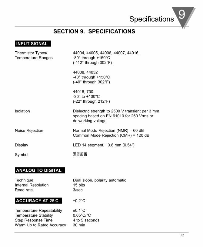
SECTION 9. SPECIFICATIONS
INPUT SIGNAL
Thermistor Types/ 44004, 44005, 44006, 44007, 44016,Temperature Ranges -80° through +150°C
(-112° through 302°F)
44008, 44032-40° through +150°C(-40° through 302°F)
44018, 700-30° to +100°C(-22° through 212°F)
Isolation Dielectric strength to 2500 V transient per 3 mm spacing based on EN 61010 for 260 Vrms or dc working voltage
Noise Rejection Normal Mode Rejection (NMR) = 60 dBCommon Mode Rejection (CMR) = 120 dB
Display LED 14 segment, 13.8 mm (0.54")
Symbol
ANALOG TO DIGITAL
Technique Dual slope, polarity automaticInternal Resolution 15 bitsRead rate 3/sec
ACCURACY AT 25˚C
Temperature Repeatability ±0.1°CTemperature Stability 0.05°C/°CStep Response Time 4 to 5 secondsWarm Up to Rated Accuracy 30 min
±0.2°C
9 Specifications
42
SECTION 9. SPECIFICATIONS (Continued)
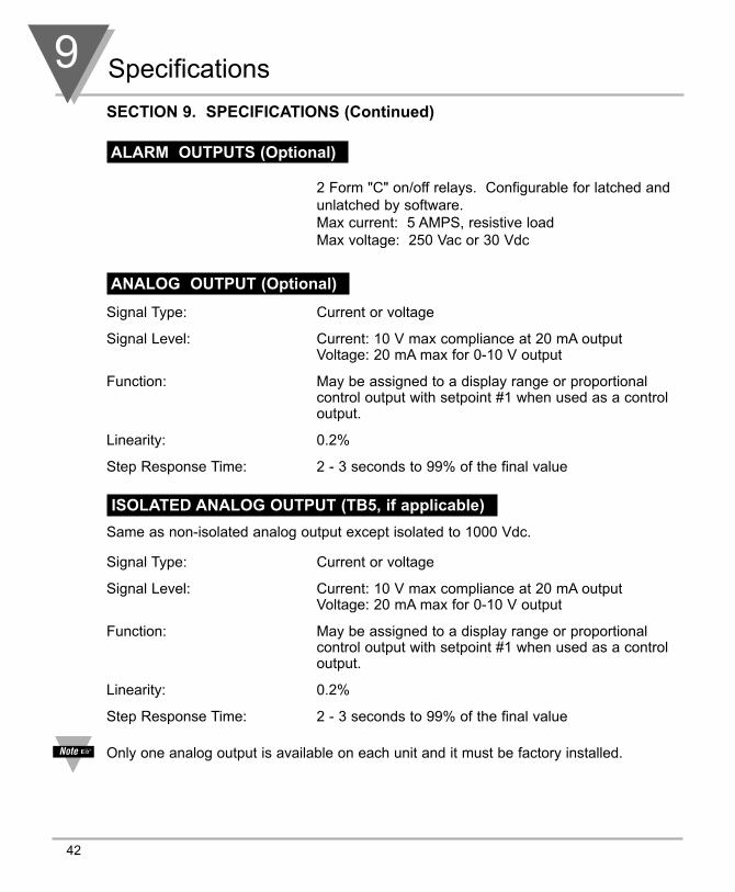
ALARM OUTPUTS (Optional)
2 Form "C" on/off relays. Configurable for latched andunlatched by software.Max current: 5 AMPS, resistive loadMax voltage: 250 Vac or 30 Vdc
ANALOG OUTPUT (Optional)
Signal Type: Current or voltage
Signal Level: Current: 10 V max compliance at 20 mA outputVoltage: 20 mA max for 0-10 V output
Function: May be assigned to a display range or proportional control output with setpoint #1 when used as a control output.
Linearity: 0.2%
Step Response Time: 2 - 3 seconds to 99% of the final value
ISOLATED ANALOG OUTPUT (TB5, if applicable)
Same as non-isolated analog output except isolated to 1000 Vdc.
Signal Type: Current or voltage
Signal Level: Current: 10 V max compliance at 20 mA outputVoltage: 20 mA max for 0-10 V output
Function: May be assigned to a display range or proportional control output with setpoint #1 when used as a control output.
Linearity: 0.2%
Step Response Time: 2 - 3 seconds to 99% of the final value
Only one analog output is available on each unit and it must be factory installed.

Specifications 9
43
SECTION 9. SPECIFICATIONS (Continued)
INPUT POWER INFORMATION
~ ac units 115/230 V~(ac) ±10%, 50/60 Hz 7 W max, power consumption (Non-Isolated Analog Output) 8 W max, power consumption (Isolated Analog Output)
dc units 10-32 Vdc6 W max, power consumption (Non-Isolated Analog Output) 7 W max, power consumption (Isolated Analog Output)
External Fuse Protection Recommended:
IEC 127-2/IIIPower Fuse115 V 125 mA @ 250 (T)230 V 63 mA @ 250 (T)
UL 248-14 (Listed Fuse)Power Fuse115 V 175 mA @ 250 V Slow-Blow230 V 80 mA @ 250 V Slow-Blow
ENVIRONMENT
Operating Temperature 0 to 50°C (32° to 122°F)
Storage Temperature -40 through 85°C (-40° to 185°F)
Relative Humidity 90% at 40°C (non-condensing)
MECHANICAL
Panel cutout 1/8 DIN 3.62 x 1.8" (45 x 92mm)
Weight 1.27 lb (574 g)
Case material Polycarbonate, 94 V-O UL rated

9 Specifications
44
SECTION 9. SPECIFICATIONS (Continued)
Table 9-1. Meter Dimensions
45,01 + 0,61/-0,00(1.772 + .024/–.000)
92,00 + 0,81/–0,00(3.622 + .032/–.000)
PANEL THICKNESS
1,5R(.06)
4 PLCS
6,4 (.25) MAX0,8 (.03) MIN
NOTE: Dimensions in Millimeters (Inches)
SIDE VIEW TOP VIEW
CASE
REAR COVER
96,0 (3.78)48,0 (1.89)
20,3 (.80)
151,
4 (5
.96)
RETAINER
FRONT BEZEL

Factory Preset Values 10
45
SECTION 10. FACTORY PRESET VALUES
Table 10-1. Factory Preset Values
Menu Item Factory Preset Values
INPT Input Type: 4004
DEC.P Decimal Point Position: FFF.F
RD.CF Reading Configuration:
R.1=F (Fahrenheit)
S1.CF Setpoint 1 Configuration:
S.1=A (Setpoint is active above)
S.2=U (Setpoint is unlatched)
S2.CF Setpoint 2 Configuration:
S.1=A (Setpoint is active above)
S.2=U (Setpoint is unlatched)
S1.DB Setpoint 1 Deadband: 003.0
S2.DB Setpoint 2 Deadband: 003.0
OT.CF Output Configuration:
O.1=E (Analog output option is enabled)
O.2=C (Analog output option is current)
OT.S.O Output Scale and Offset:
032° - 212.0°F = 4-20 mA dc
SP1 Setpoint 1 Value: 000.0
SP2 Setpoint 2 Value: 000.0

46
CE APPROVALS INFORMATION
This product conforms to the EMC directive 89/336/EEC amended by 93/68/EEC,and with the European Low Voltage Directive 72/23/EEC.
Electrical Safety EN61010-1:2001Safety requirements for electrical equipment for measurement, control and laboratory.Double InsulationPollution Degree 2Dielectric withstand Test per 1 min
• Power to Input/Output: 2300 Vac (3250 Vdc)• Power to Input/Output: 500 Vac (720 Vdc)
(Low Voltage dc Power Option*)
• Power to Relays Output: 2300 Vac (3250 Vdc)• Relay 1 to Relay 2: 2300 Vac (3250 Vdc)• Isolated Analog to Inputs: 1000 Vac (1420 Vdc)• Analog to Inputs: No Isolation
Measurement Category ICategory I are measurements performed on circuits not directly connected to the MainsSupply (power). Maximum Line-to-Neutral working voltage is 50 Vac/dc. This unitshould not be used in Measurement Categories II, III, IV.
Transients Overvoltage Surge (1.2 / 50uS pulse)• Input Power: 2500 V• Input Power: 500 V
(Low Voltage dc Power Option*)
• Isolated Analog: 500 V• Input/Output Signals: 500 V
Note: *Units configured for external low power dc voltage, 10-32 Vdc (Basic Insulation)
EMC EN61326:1997 + and A1:1998 + A2:2001Immunity and Emissions requirements for electrical equipment for measurement, control andlaboratory.
• EMC Emissions Table 4, Class B of EN61326• EMC Immunity** Table 1 of EN61326
Note: **I/O signal and control lines require shielded cables and these cables must be located on conductive cable trays or in conduits. Furthermore, the length of these cables should not exceed 30 meters
Refer to the EMC and Safety installation considerations (Guidelines) of this manual foradditional information.

Notes
47

Notes
48
WARRANTY/DISCLAIMEROMEGA ENGINEERING, INC. warrants this unit to be free of defects in materials and workmanship for a period ofone (1) year from the date of purchase. In addition to OMEGA’s standard warranty period, OMEGA Engineering willextend the warranty period for four (4) additional years if the warranty card enclosed with each instrument isreturned to OMEGA.
If the unit malfunctions, it must be returned to the factory for evaluation. OMEGA’s Customer Service Departmentwill issue an Authorized Return (AR) number immediately upon phone or written request. Upon examination byOMEGA, if the unit is found to be defective, it will be repaired or replaced at no charge. OMEGA’s WARRANTY doesnot apply to defects resulting from any action of the purchaser, including but not limited to mishandling, improperinterfacing, operation outside of design limits, improper repair, or unauthorized modification. This WARRANTY isVOID if the unit shows evidence of having been tampered with or shows evidence of having been damaged as aresult of excessive corrosion; or current, heat, moisture or vibration; improper specification; misapplication; misuseor other operating conditions outside of OMEGA’s control. Components which wear are not warranted, including butnot limited to contact points, fuses, and triacs.
OMEGA is pleased to offer suggestions on the use of its various products. However, OMEGA neitherassumes responsibility for any omissions or errors nor assumes liability for any damages that result fromthe use of its products in accordance with information provided by OMEGA, either verbal or written.OMEGA warrants only that the parts manufactured by it will be as specified and free of defects. OMEGAMAKES NO OTHER WARRANTIES OR REPRESENTATIONS OF ANY KIND WHATSOEVER, EXPRESS ORIMPLIED, EXCEPT THAT OF TITLE, AND ALL IMPLIED WARRANTIES INCLUDING ANY WARRANTY OFMERCHANTABILITY AND FITNESS FOR A PARTICULAR PURPOSE ARE HEREBY DISCLAIMED. LIMITATIONOF LIABILITY: The remedies of purchaser set forth herein are exclusive, and the total liability of OMEGAwith respect to this order, whether based on contract, warranty, negligence, indemnification, strict liabilityor otherwise, shall not exceed the purchase price of the component upon which liability is based. In noevent shall OMEGA be liable for consequential, incidental or special damages.
CONDITIONS: Equipment sold by OMEGA is not intended to be used, nor shall it be used: (1) as a “BasicComponent” under 10 CFR 21 (NRC), used in or with any nuclear installation or activity; or (2) in medicalapplications or used on humans. Should any Product(s) be used in or with any nuclear installation or activity,medical application, used on humans, or misused in any way, OMEGA assumes no responsibility as set forthin our basic WARRANTY/DISCLAIMER language, and, additionally, purchaser will indemnify OMEGA and holdOMEGA harmless from any liability or damage whatsoever arising out of the use of the Product(s) in such amanner.
RETURN REQUESTS/INQUIRIESDirect all warranty and repair requests/inquiries to the OMEGA Customer Service Department. BEFORERETURNING ANY PRODUCT(S) TO OMEGA, PURCHASER MUST OBTAIN AN AUTHORIZED RETURN(AR) NUMBER FROM OMEGA’S CUSTOMER SERVICE DEPARTMENT (IN ORDER TO AVOIDPROCESSING DELAYS). The assigned AR number should then be marked on the outside of the returnpackage and on any correspondence.The purchaser is responsible for shipping charges, freight, insurance and proper packaging to preventbreakage in transit.
FOR WARRANTY RETURNS, please have the following information available BEFORE contacting OMEGA:1. Purchase Order number under which the product
was PURCHASED,2. Model and serial number of the product under
warranty, and3. Repair instructions and/or specific problems
relative to the product.
FOR NON-WARRANTY REPAIRS, consult OMEGA forcurrent repair charges. Have the following informationavailable BEFORE contacting OMEGA:1. Purchase Order number to cover the COST
of the repair,2. Model and serial number of product, and3. Repair instructions and/or specific problems
relative to the product.
OMEGA’s policy is to make running changes, not model changes, whenever an improvement is possible. This affords our customersthe latest in technology and engineering.
OMEGA is a registered trademark of OMEGA ENGINEERING, INC.
© Copyright 2005 OMEGA ENGINEERING, INC. All rights reserved. This document may not be copied, photocopied, reproduced,translated, or reduced to any electronic medium or machine-readable form, in whole or in part, without the prior written consent ofOMEGA ENGINEERING, INC.
PATENT NOTICE: This product is covered by one or more of the following patents: U.S. Pat. No. Des. 336,895; 5,274,577 /CANADA 2052599; 2052600 / ITALY 1249456; 1250938 / FRANCE BREVET No. 91 12756 / SPAIN 2039150; 2048066 /UK PATENT No. GB2 249 837; GB2 248 954 / GERMANY DE 41 34398 C2. USED UNDER LICENSE. Other US and InternationalPatents pending or applied for.

M1848/100511798ML-95B
Where Do I Find Everything I Need for Process Measurement and Control?
OMEGA…Of Course!Shop on line at www.omega.comTEMPERATURE Thermocouple, RTD & Thermistor Probes, Connectors, Panels & Assemblies Wire: Thermocouple, RTD & Thermistor Calibrators & Ice Point References Recorders, Controllers & Process Monitors Infrared Pyrometers
PRESSURE, STRAIN AND FORCE Transducers & Strain Gauges Load Cells & Pressure Gauges Displacement Transducers Instrumentation & Accessories
FLOW/LEVEL Rotameters, Gas Mass Flowmeters & Flow Computers Air Velocity Indicators Turbine/Paddlewheel Systems Totalizers & Batch Controllers
pH/CONDUCTIVITY pH Electrodes, Testers & Accessories Benchtop/Laboratory Meters Controllers, Calibrators, Simulators & Pumps Industrial pH & Conductivity Equipment
DATA ACQUISITION Data Acquisition & Engineering Software Communications-Based Acquisition Systems Plug-in Cards for Apple, IBM & Compatibles Datalogging Systems Recorders, Printers & Plotters
HEATERS Heating Cable Cartridge & Strip Heaters Immersion & Band Heaters Flexible Heaters Laboratory Heaters
ENVIRONMENTALMONITORING AND CONTROL Metering & Control Instrumentation Refractometers Pumps & Tubing Air, Soil & Water Monitors Industrial Water & Wastewater Treatment pH, Conductivity & Dissolved Oxygen Instruments