ship righ t - class direct · pdf fileship righ t design and construction abcd. ... yaw in...
TRANSCRIPT

AAddddiittiioonnaallDDeessiiggnn PPrroocceedduurreess
Guidance notes for liq ue f ied gascarriers adopting IMO Type Bindependent tank s primarilyconstructed o f p lane surfaces
Octob e r 2012
ShipRightDesign and construction
ABCD

AAddddiittiioonnaallDDeessiiggnn PPrroocceedduurreess
Guidance notes for liq ue f ied gascarriers adopting IMO Type Bindependent tank s primarilyconstructed o f p lane surfaces
Octob e r 2012
ShipRightDesign and construction
ABCD

Lloyd’s Register 71 Fenchurch Street LondonEC3M 4BST: +44 (0)20 7709 9166F: +44 (0)20 7488 4796E: [email protected]
www.lr.org
Document History
DDooccuummeenntt DDaattee NNootteess
December 2010 General release
October 2012 Updated version
ABCD
Lloyd’s Register is a trading name of Lloyd’s Register Group Limited and its subsidiaries.For further details please see http://www.lr.org/entities.
Lloyd's Register Group Limited, its affiliates and subsidiaries and their respective officers,employees or agents are, individually and collectively, referred to in this clause as 'Lloyd'sRegister'. Lloyd's Register assumes no responsibility and shall not be liable to any personfor any loss, damage or expense caused by reliance on the information or advice in thisdocument or howsoever provided, unless that person has signed a contract with therelevant Lloyd's Register entity for the provision of this information or advice and in thatcase any responsibility or liability is exclusively on the terms and conditions set out in thatcontract.
© Lloyd’s Register, 2012
LLOYD’S REGISTER
CCoonntteennttss
Guidance notes for liq ue f ied gas carriers, Octob er 2012
SSEECCTTIIOONN 11 IINNTTRROODDUUCCTTIIOONN 22
SSEECCTTIIOONN 22 GGEENNEERRAALL 22
SSEECCTTIIOONN 33 IINNIITTIIAALL SSCCAANNTTLLIINNGG OOFF CCAARRGGOO TTAANNKKSS 33
SSEECCTTIIOONN 44 SSTTRRUUCCTTUURRAALL AASSSSEESSSSMMEENNTT OOFF HHUULLLL CCAARRGGOO TTAANNKKSS AANNDD TTAANNKK SSUUPPPPOORRTTIINNGG SSYYSSTTEEMM 44
SSEECCTTIIOONN 55 FFAATTIIGGUUEE CCRRAACCKK IINNIITTIIAATTIIOONN,, PPRROOPPAAGGAATTIIOONN AANNDD LLEEAAKK RRAATTEE AANNAALLYYSSIISS OOFF CCAARRGGOO TTAANNKKSS 66
SSEECCTTIIOONN 66 FFAATTIIGGUUEE DDEESSIIGGNN AASSSSEESSSSMMEENNTT OOFF HHUULLLLAANNDD TTAANNKK SSUUPPPPOORRTTIINNGG SSYYSSTTEEMM ((FFDDAA)) 1122
SSEECCTTIIOONN 77 CCOONNSSTTRRUUCCTTIIOONN MMOONNIITTOORRIINNGG OOFF HHUULLLL,,CCAARRGGOO TTAANNKKSS SSUUPPPPOORRTTIINNGG SSYYSSTTEEMM((CCMM)),, AANNDD CCAARRGGOO TTAANNKKSS ((CCTTII)) 1122
SSEECCTTIIOONN 88 MMAATTEERRIIAALLSS OOFF CCOONNSSTTRRUUCCTTIIOONN 1133
SSEECCTTIIOONN 99 IINNSSUULLAATTIIOONN 1144
SSEECCTTIIOONN 1100 RREEFFEERREENNCCEESS 1144
AAPPPPEENNDDIIXX 11 WWEELLDD TTOOEE SSTTRREESSSS CCOONNCCEENNTTRRAATTIIOONN FFAACCTTOORR FFOORR CCRRAACCKK PPRROOPPAAGGAATTIIOONN AASSSSEESSSSMMEENNTT 1166
AAPPPPEENNDDIIXX 22 SSTTRREESSSS CCOONNCCEENNTTRRAATTIIOONNSS DDUUEE TTOO CCOONNSSTTRRUUCCTTIIOONN TTOOLLEERRAANNCCEESS 1177
AAPPPPEENNDDIIXX 33 NNEEWWMMAANN--RRAAJJUU EEQQUUAATTIIOONNSS 1177
AAPPPPEENNDDIIXX 44 NNOOMMIINNAALL AACCCCEEPPTTAANNCCEE CCRRIITTEERRIIAA FFOORR CCRRAACCKK PPRROOPPAAGGAATTIIOONN AASSSSEESSSSMMEENNTT 1199
CONTENTS


1LLOYD’S REGISTER 1
Guidance notes for liquefied gascarriers adopting IMO Type Bindependent tanks primarily
constructed of plane surfaces
Guidance notes for liquefied gas carriers, Octob er 2012
Chapter 1SECTION 1
Section 1: IntroductionSection 2: General
Section 3: Initial scantling of cargo tanksSection 4: Structural assessment of hull, cargo
tanks and tank supporting systemSection 5: Fatigue crack initiation, propagation
and leak rate analysis of cargo tanksSection 6: Fatigue design assessment of hull and
tank supporting system (FDA)Section 7: Construction monitoring of hull, cargo
tanks supporting system (CM)and cargo tanks (CTI)
Section 8: Materials of constructionSection 9: Insulation
Section 10: ReferencesAppendix 1: Weld toe stress concentration factor
for crack propagation assessmentAppendix 2: Stress concentrations due to
construction tolerancesAppendix 3: Newman-Raju equations
Appendix 4: Nominal acceptance criteria forcrack propagation assessment
Guidance notes for liquefied gas carriers adopting IMO TypeB independent tanks primarily constructed of plane surfaces
Guidance notes for liquefied gas carriers, Octob er 2012
Chapter 1SECTIONS 1 & 2
LLOYD’S REGISTER2
� SSeeccttiioonn 11:: IInnttrroodduuccttiioonn
1.1 Purpose
1.1.1 This document is intended to provide guidance todesigners, operators and Lloyd's Register Surveyors on theclassification and certification of liquefied gas carriersadopting IMO Type B independent tanks primarilyconstructed of plane surfaces. It does not in any wayreplace requirements given in the relevant Lloyd's RegisterRules and Regulations and IGC code but is intended tosupport and complement them.
1.1.2 Type B independent tanks are defined in the Rulesand Regulations for the Construction and Classification ofShips for the Carriage of Liquefied Gases in Bulk [1],(hereinafter referred to as the Gas Ship Rules), paragraph4.2.4.3, as tanks which are designed using model tests,refined analytical tools and analysis methods to determinestress levels, fatigue life and crack propagationcharacteristics. Independent tanks that comply with theType B requirements are permitted to adopt a reducedsecondary barrier according to the Rules.
1.1.3 These Guidance Notes are primarily intended forapplication to liquefied gas carriers adopting Type Bindependent prismatic cargo tanks constructed of stiffenedplated structure supported by deep girders and/ortransverse primary members. Other novel tank designs willbe specially considered. Guidance is provided for thefollowing areas:• the cargo tanks;• the supporting structures between the cargo tanks
and the main hull structures; and• the hull structure where relevant.
1.1.4 These Guidance Notes are intended to be a livedocument and are subject to change without notice.
�� SSeeccttiioonn 22:: GGeenneerraall
2.1 These Guidance Notes are, in general terms,applicable to IMO Type B prismatic independent cargo tanksconstructed of materials permitted by the Gas Ship Rules[1], typically aluminium 5083 alloys, austenitic stainlesssteels and nickel steels for LNG and low temperature carbonmanganese steels for LPG. Lloyd’s Register also providesdesign guidance for independent cargo tanks of othercategorisations, e.g. Type A, and configurations, e.g.spherical. The Lloyd’s Register Design Support Officesshould be consulted for advice in these containmentsystems.
2.2 The independent cargo tanks, the hull structure andtank supporting structures are to comply with the Gas ShipRules [1].
2.3 The typical hull class notations to LNG carrierscould be assigned as below, but additional class notationsand descriptive notes will be applicable depending on thespecification agreed between the Owner and the Builder.�100A1, Liquefied Gas Carrier, Ship type 2G, methane(LNG) in independent prismatic tanks type B,maximum vapour pressure 0,25 bar, minimumtemperature minus 163°C, ShipRight (SDA), *IWS, LI with descriptive notes ’ShipRight (FDA, CM), ETA’.
2.4 The determination of dynamic loads should takeaccount of the long-term distribution of ship motions,including the effects of surge, sway, heave, roll, pitch andyaw in irregular seas which the ship will experience during itsoperating life (normally taken to correspond to 100 millionwave encounters). The Gas Ship Rules [1] permit a reductionin dynamic loads due to necessary speed reduction andvariation of heading when this consideration has also formedpart of the hull strength assessment.
2.5 Ships for restricted service may be given specialconsideration.
2.6 The dynamic loads should be determined fromdirect calculation methods to be agreed with Lloyd’sRegister, but guidance formulae for accelerationcomponents given in 4.12 of Gas Ship Rules [1] may beused for initial scantlings estimation.
2.7 The accelerations acting on tanks are estimated attheir centre of gravity and include the following components:• vertical acceleration: motion accelerations of heave,
pitch and, possibly, roll (normal to the ship base);• transverse acceleration: motion accelerations of
sway, yaw and roll; and gravity component of roll;• longitudinal acceleration: motion accelerations of
surge and pitch, and gravity component of pitch.
2.8 While the adequacy of the cargo tank and itssupporting structure is required to be determined using asophisticated approach, e.g. finite element methods anddirectly calculated wave loads, Chapter 3 of this documentprovides guidance on the determination of initial scantlingsof secondary members and tank boundary plating whichshould be taken as a minimum scantling requirement.General guidance on direct calculation for strengthassessment is described in Chapter 4 of this document anddetailed calculation procedure is contained in the ShipRightSDA procedure for liquefied gas carriers adopting prismaticType B independent tanks [28]. Chapter 5 provides
Guidance notes for liquefied gas carriers adopting IMO TypeB independent tanks primarily constructed of plane surfaces
LLOYD’S REGISTER 3
Guidance notes for liquefied gas carriers, Octob er 2012
Chapter 1SECTIONS 2 & 3
guidance on the fatigue and crack propagation assessmentfor the cargo tank and its supporting structure.
2.9 The Gas Ship Rules [1] require a partial secondarybarrier to be sufficient to contain any cargo leakage arisingfrom a fatigue crack penetrating the tank skin at any locationfor a 15 day duration and to ensure that the ship’s hull isprotected from direct contact with the leakage. Clear of thepartial secondary barrier, provision such as a spray shieldshould be made to deflect any liquid cargo entering intospace between the primary and secondary barriers and tokeep the temperature of the hull structure to a safe level.
2.10 The extent of the secondary barrier should bedetermined on the basis of cargo leakage corresponding tothe extent of failure resulting from the load spectrum referredto in paragraph 4.3.4.4 of the Gas Ship Rules [1] after theinitial detection of a primary barrier breach. Due accountmay be taken of liquid evaporation, rate of leakage and otherrelevant factors. Guidance on the estimation of leakage rateis provided in Chapter 5 of this document.
2.11 Chapters 6 and 7 provide general guidance on theapplicability of the ShipRight Fatigue Design Assessment(FDA) and Construction Monitoring (CM) procedures to aliquefied gas carrier employing prismatic Type Bindependent cargo tanks.
2.12 Chapters 8 and 9 provide general guidance on therequirement concerning material of construction andinsulation respectively.
� SSeeccttiioonn 33:: IInniittiiaall ssccaannttlliinngg ooffccaarrggoo ttaannkkss
3.1 Independent prismatic Type B cargo tanks are, ingeneral, provided with liquid tight centreline longitudinalbulkheads with opening in way of liquid dome area forming acommon gas phase similar to Type A LPG tanks. The samefilling height is generally assumed at both port and starboardsides for sea-going conditions. The centreline bulkhead is tobe designed to withstand a static differential head of ’oneside full and the other side empty‘ in harbour condition and atransverse dynamic acceleration head in sea-goingcondition, with the maximum cargo density at the designtemperature. The hydro-pneumatic tank test conditionsshould be representative of the design loads on thecentreline bulkhead in accordance with these loadscenarios. Special consideration will be given to ships thatare anticipated to operate in a moored condition in harshweather.
3.2 Generally, the scantlings of cargo tanks primarilyconstructed of plane surfaces are not to be less than thosedetermined by the formulae given in section 4.4.4 of the GasShip Rules [1] for Type A independent tanks. The formulaegiven in this chapter of the guidance notes have beenadapted to accommodate a wider range of material.
3.3 The initial scantlings are to be verified by directcalculation procedures at a high confidence level. It isrecommended that the assumptions made and theproposed calculation procedures be agreed with Lloyd’sRegister at an early stage. When necessary, model or othertests may be required. Subsequent chapters of thisdocument and the SDA procedure are intended to providepractical guidance to the designer.
3.4 Minimum thickness of cargo tanks. No part ofcargo tank plating and internal structural members is to beless than 7,5 mm in thickness.
3.5 Boundary plating of cargo tanks. The thicknessof plating forming the boundaries of cargo tanks is not to beless than 7,5 mm, nor less than:
t = 0,011s f (Peq k)1/2 mmwhere
s = spacing of stiffeners, in mm
f = 1,1 – but need not exceed 1,0
S = spacing of primary members, in metresPeq = the internal pressure head, in bar, as derived from
Gas Ship Rules 4.3.2.1 and 4.3.2.2, andmeasured at a point on the plate one third of thedepth of the plate above its lower edge
k = higher tensile steel factor applicable to carbonmanganese and nickel steels, see Pt 3, Ch 2,1.2of Rules for Ships
For stainless steel and aluminium, k is defined thus:
whereRe = 0,2 per cent proof stress as defined in 4.5.1.7 of
the Gas Ship Rules [1]. Subject to specialconsideration by the Administration, account maybe taken of enhanced yield stress at lowtemperature, as indicated in 4.5.1.7.2 of the GasShip Rules. A reduced value will be speciallyconsidered in way of weldments for higherstrength alloys such as A5083-H321.
Final scantlings are to be verified in accordance with theevaluation results from the strength analysis using 3-D FEMoutlined in Section 4 and fatigue and crack propagationanalysis outlined in Section 5. However, the final thicknessesare not to be less than those calculated using the above
235Re
s2500S

Guidance notes for liquefied gas carriers adopting IMO TypeB independent tanks primarily constructed of plane surfaces
Guidance notes for liquefied gas carriers, Octob er 2012
Chapter 1SECTIONS 3 & 4
LLOYD’S REGISTER4
formula. It is recommended that the initial tank skinthickness estimate also take account of the permissiblestress obtained from simplified fatigue calculations. This maybe determined from classical plate bending formula and asuitable fatigue joint class, including an estimate of themembrane stress component from any global deflections ofthe tank.
3.6 Boundary rolled and built-up stiffeners of cargotanks. The section modulus of rolled or built-up stiffeners onplating forming tank boundaries is not to be less than thatrequired by the following:
Z =
wheres = spacing of stiffeners, in mmle = effective length of stiffening member, in metres,
see Pt 3, Ch 3,3.3 of Rules for ShipsPeq = the internal pressure head, in bar, as derived from
Gas Ship Rules 4.3.2.1 and 4.3.2.2 andmeasured at the middle of effective span le
k = higher tensile steel factor applicable to carbonmanganese and nickel steels, see Pt 3, Ch 2,1.2of Rules for Ships
γ = 1,4 for rolled or built-up sections and 1,6 for flatbars
ω = see Fig. 1.9.1 in Pt 4, Ch 1 of the Rules for Shipsfs = 2,7 for nickel steels and carbon manganese steels
and 3,9 for austenitic steels and aluminium alloysFor stainless steel and aluminium, k is defined thus:
whereRe = 0,2 per cent proof stress as defined in 4.5.1.7 of
the Gas Ship Rules. Subject to specialconsideration by the Administration, account maybe taken of enhanced yield stress at lowtemperature, as indicated in 4.5.1.7.2 of the GasShip Rules. A reduced value will be speciallyconsidered in way of weldments for higherstrength alloys such as A5083-H321.
Final scantlings are to be verified in accordance with theevaluation results from strength analysis using 3-D FEMoutlined in Section 4 and fatigue and crack propagationanalysis outlined in Section 5. However, the final scantlingsare not to be less than those calculated using the aboveformula. It is recommended that the initial tank stiffenermodulus estimate also take account of the permissiblestress obtained from simplified fatigue calculations. This maybe determined from classical beam bending formula and asuitable fatigue joint class, including an estimate of thestress components arising from any global deflections of thetank.
235Re
Peq s k le2
fs γ (ω1 + ω2 + 2)
3.7 Primary members of cargo tanks. The scantlingsof primary supporting members are to be verified using 3-DFEM strength analysis as well as fatigue and crackpropagation analysis, but initial dimensioning may be guidedby LR 4.4-05 of the Gas Ship Rules [1] accounting for thematerial yield stress as indicated in 3.6. The structuralanalysis is to take account of the internal pressure defined in4.3.2 of Gas Ship Rules and also those resulting fromstructural test loads. Proper account is also to be taken ofstructural model end constraints, shear and axial forcespresent and any interaction from double bottom structurethrough the cargo tank support.
3.8 Connection of stiffeners to primary supportingmembers of cargo tanks. In assessing the arrangement atintersections of continuous secondary and primarymembers, the requirements of Pt 3, Ch 10,5.2 of Rules forShips [5] are to be complied with using the requirements forother ship types. The permissible direct and shear stressesin way of the connection will be specially considered forstainless steel and aluminium. The total load, P, in kN(tonne-f), is to be derived using the internal pressure head,P, in bar as given by 4.3.2.1 and 4.3.2.2 of Gas Ship Rules[1] and the following formulae:(a) In general:
P = 100 (Sw – 0,5s1) s1 Peq kN(b) For wash bulkheads:
P = 120 (Sw – 0,5s1) s1 Peq kNwhereSw = spacing of primary members, in metress1 = spacing of secondary members, in metres
Those end connections in way of representative tanksupports are to be assessed using fine mesh FEM todemonstrate satisfactory stress levels and fatigue strength.Typical primary member web stiffeners are also to beassessed for fatigue strength.
� SSeeccttiioonn 44:: SSttrruuccttuurraall aasssseessssmmeennttooff hhuullll,, ccaarrggoo ttaannkkssaanndd ttaannkk ssuuppppoorrttiinnggssyysstteemm
4.1 Structural assessment of primary members of hull,cargo tanks and tank supporting system is to be made inaccordance with the SDA procedure [28]. Alternatively,equivalent design wave load cases determined using directload and motions calculation may be employed inconsultation with Lloyd’s Register.

Guidance notes for liquefied gas carriers adopting IMO TypeB independent tanks primarily constructed of plane surfaces
LLOYD’S REGISTER 5
Guidance notes for liquefied gas carriers, Octob er 2012
Chapter 1SECTION 4
4.2 Cargo tanks should be supported by the hull in amanner which will prevent bodily movement of the tankunder static and dynamic loads while allowing contractionand expansion of the tank under temperature variations andhull deflection without undue stressing of the tank and of thehull.
4.3 The tanks with supports should be designed for astatic angle of 30° without exceeding the allowable criteriagiven in the SDA procedure.
4.4 The strength assessment of the supports should bebased on the most probable largest resulting accelerationthat the ship will encounter during its operating life (normallytaken to correspond to a probability level of 10–8), taking intoaccount rotational as well as translational effects. Thisacceleration in a given direction may be determined usingthe ’acceleration ellipse‘ as shown in Fig. 4.1 of Gas ShipRules [1]. The half axes of the ’acceleration ellipse‘ are to bedetermined according to 4.3.2.2 of Gas Ship Rules.
4.5 Suitable supports should be provided to withstanda collision force on the tank corresponding to one half theweight of the tank and cargo in the forward direction andone quarter the weight and cargo in the aft direction withoutdeformation likely to endanger the tank structure.
4.6 Anti-flotation arrangements should be provided forthe independent tanks. The anti-flotation arrangementshould be suitable to withstand an upward force caused byan empty tank in a hold space flooded to the summer loaddraught of the ship, without plastic deformation likely toendanger the hull structure.
4.7 The clearance between the anti-flotation chocksand the ship’s hull are to be verified by direct calculations inaccordance with the SDA procedure [28] to ensure that theyare adequate to prevent contact in all normal operationalconditions.
4.8 Thermal analysis.
4.8.1 Thermal stresses in the independent cargo tanksshould be evaluated for several cargo loading steps startingfrom the cool-down to the full cargo loading, and thesecalculations should cover the main areas of interest includingbuckling strength of the top skin, the bottom skin and theside skin. In addition to the thermal loading, thesecalculations should also include mechanical loading due toself weight of the tank, internal pressure, static interactionwith the tank supporting system, and for cargo loading, themass of liquefied gas at the appropriate filling level.
4.8.2 During the cool-down period, thermal stressescould be calculated at a large number discrete of time steps.However, for practical reasons it is usually necessary torestrict these to a few typical time steps at which the largestthermal stresses can be anticipated. By examining thetemperature-time curves for the cargo tank, it should bepossible to determine those time steps at which the largestdifferences in temperature occur. These, in addition to thetime step at which the liquefied gas level passes through themid depth, then give the discrete points in time for thestructural analysis.
4.8.3 Temperature distributions at these time steps arethen input into the SDA FE model described in the SDAprocedure [28]. Combined stresses, including themechanical loadings previously analysed in that section, canthen be obtained and compared with allowable levels givenin Tables 2.5.1, 2.5.2 and 2.6.1 of this document.
4.8.4 It is possible that thermal analysis may identify thatthe cargo tanks (or certain parts of them) need to be cooledto an identified temperature before the filling of liquefied gascan be commenced. For instance, in the case where thecrown of the tank is put into compression, if it remains warmwhile the lower regions of the tank are at LNG temperature,a possible solution would be either to increase the platingthickness at the tank crown to improve its bucklingcapability, or require that it is cooled (by spraying) down toan identified temperature before filling commences. Theoperational cooling-down procedure may be taken intoaccount as part of the transient thermal analysis of the cargotank.
4.9 Sloshing analysis.
4.9.1 When partial filling is contemplated, the risk ofsignificant loads due to sloshing induced by any of the shipmotions referred to in Section 2.7 should be considered.When risk of significant sloshing induced loads is found tobe present, special tests and calculations will, in general, berequired.
4.9.2 Where loading conditions are proposed includingone or more partially filled tanks, calculations or model testswill be required to show that the resulting loads andpressure are within acceptable limits for the scantlings of thetanks. Additionally, investigations should be made to ensurethat the internal structure, equipment and pipe workexposed to fluid motion are of adequate strength.
Guidance notes for liquefied gas carriers adopting IMO TypeB independent tanks primarily constructed of plane surfaces
Guidance notes for liquefied gas carriers, Octob er 2012
Chapter 1SECTIONS 4 & 5
LLOYD’S REGISTER6
tolerances defined by the builders. Additional calculationsmaybe required for the other tanks if they are of a differentsize, configuration or scantling.
5.2 Loading spectra.
5.2.1 The actual loading spectra experienced by anoperating liquefied gas carrier will reflect the number ofloaded and ballast voyages, the number of loading anddischarge cycles (including emergency pressure discharges),operation in partially loaded conditions, and the sea statesencountered. For fatigue crack initiation and propagationassessments, the spectrum for a minimum design life of 20 years may normally be made up from the followingcomponents:(a) Load condition (not to be taken as less than 0,5 x 10⁸
cycles).(b) Ballast condition.(c) Load and discharge cycles (not to be taken as less
than 1,000).In any case the total number of wave cycles at sea shouldnot be less than 108.Fatigue stress spectra in the cargo tanks are obtained fromthe combination of the most probable maximumaccelerations, (i.e., at a level of 108) in the normal fullyloaded and ballast conditions, with the ship proceeding at itsendurance speed. It is not necessary to consideraccelerations for infrequent partly loaded conditions, whichgenerally determine the structure strength. Combineddynamic stresses are derived as described below. These aredistributed over the ship life according to the Weibullprobability function with a shape factor that may be taken as1,0 for simplicity for each loading condition. Alternatively thismay be derived based on North Atlantic tradingenvironment.
5.3 Determination of maximum response forfatigue assessment.
5.3.1 Cargo tank maximum lifetime accelerations are tobe determined using ship motions analysis, assuming thefollowing:• Full Load condition, max. cargo SG (conditions giving
conservative estimation of tank accelerations may beselected).
• Normal ballast condition (may be ignored for preliminary assessment).
• North Atlantic Wave Scatter Data (e.g. IACS Rec34,or other recognised source of reference) to be used.
• Equal heading probability may be assumed.• Realistic speed reduction may be considered but is
not to be taken as less than 75 per cent of the ship’sservice speed.
• ISSC wave spectrum may be assumed.
4.9.3 Where centreline longitudinal bulkhead and washbulkhead are provided across mid length of each cargotank, it may be reasonable to assume that the internal hullstructures inside the tanks will significantly inhibit liquidmotion due to sloshing. In this regard, the risk of significantloads due to sloshing induced by any of the ship motions forthis type of cargo tank is generally considered unlikely to behigh.
4.9.4 However, an initial assessment can be made, usingthe level 1 investigation outlined in the Structural DesignAssessment (SDA) procedures for sloshing loads andscantling assessment [21] to determine whether or not afurther assessment is required on tanks partially filled withliquids, using a higher level of sloshing investigation specifiedin [21] or an equivalent CFD based method.
4.9.5 Where unusual structural configurations within thecargo tank area are proposed, for example by omitting thecentreline bulkhead, then special consideration is to begiven to verify the adequacy of the relevant structures for allthe intended partial filling levels.
� SSeeccttiioonn 55:: FFaattiigguuee ccrraacckkiinniittiiaattiioonn,, pprrooppaaggaattiioonnaanndd lleeaakk rraattee aannaallyyssiissooff ccaarrggoo ttaannkkss
5.1 Design principles.
5.1.1 The IGC code requires that for type B independenttanks, the integrity of the structure is to be assessed toensure the likelihood of fatigue failure occurring to besufficiently low, and secondly that, even if a crackpenetrating the tank were to occur, the subsequent leakagecan be contained and controlled over at least a 15 dayperiod in order to allow time for the tank to be discharged.
5.1.2 Lloyd’s Register considers that verification shouldalso be carried out to ensure that small defects of themaximum size which could escape detection by non-destructive examination (NDE) would not propagate throughthe thickness of the containment structure within theanticipated ship life.
5.1.3 Fatigue, crack propagation and leakagecalculations as described below should be performed atleast for the No. 1 cargo tank and for No. 2 or the aft-mosttank, whichever is more severely loaded. The latter may beconsidered representative for the remaining tanks. Principalstresses in way of the weld, or detail, are considered,amplified by concentration factors due to shape, whereappropriate, and due to the maximum constructional
Guidance notes for liquefied gas carriers adopting IMO TypeB independent tanks primarily constructed of plane surfaces
LLOYD’S REGISTER 7
Guidance notes for liquefied gas carriers, Octob er 2012
Chapter 1SECTION 5
• Minimum 20 years’ design life should be assumed.Details of the calculations, e.g. effect of bilge keels onviscous roll damping, etc., are to be submitted to Lloyd’sRegister for consideration.
5.4 Design Wave Load Cases for FatigueAssessment.
5.4.1 The Gas Ship Rules [1] stipulates that for Type Btanks, refined analytical tools and analysis methods are tobe employed to determine the stress levels and fatigue life.In this connection, a stochastic spectral approach along thelines of the ShipRight FDA Level 3 procedures [23] may beappropriate. In lieu of a full stochastic spectral fatigueassessment, a simplified approach [8] is proposed, wherebyfor each of No. 1 and No. 2 cargo tanks, the equivalentdesign wave conditions for maximum vertical, transverseand longitudinal acceleration respectively are obtained byperforming the following steps:• Determine the RAO’s of vertical, transverse and longi-
tudinal accelerations at the cargo tank centroid.• Select the heading and wave length giving peak
response for each of the vertical, transverse andlongitudinal accelerations.
• Obtain design wave amplitude by scaling maximumlifetime response value with response value from unitregular wave.
For each equivalent design wave condition above withunique heading, wave length and wave amplitude, applyinternal and external loads to full length FE model at discretetime steps over one wave cycle. At each checkpoint,determine the stress range for each design wave conditionfrom the stress-time history. The maximum stress rangefrom all design wave conditions is to be selected for fatiguecalculation.
5.4.2 For the assessment of seats and chocks, inaddition to the accelerations, the maximum vertical wavebending moment, roll angle and external bottom pressuremay need to be considered in deriving the maximum stressrange. Where tank support arrangement and/or tankconfiguration are sufficiently different, additional tanks mayneed to be assessed.
5.4.3 In any case, a suitable approach for determining thelong-term stress range spectrum should be submitted toLloyd’s Register for consideration.
5.5 Stress Determination for Fatigue Assessment.
5.5.1 Nominal Stress Approach – Screening Assessment.Due to the numerous welded joints and hence potentialcrack initiation locations in a prismatic tank, a screeningapproach is advocated, whereby the fatigue lives forsecondary members in way of web stiffener heel/toe boxingfillet weld connections, plate panel edge fillet weld toes andplate butt joints are determined, based on nominal stressand suitable design S-N curves, to select the most criticallocations for further fine mesh modelling and hot spot stressassessment.
5.5.2 Hot Spot Stress Approach – Fine Mesh FEM. Inway of other locations, e.g. cruciform joints, tank corner skinbutts, seats and chocks, primary member butt joints andbracket toes, etc., hot spot stress shall be determined fromfine mesh FE models. Four noded shell elements of a sizeapproximately equal to the plate thickness are acceptable.Surface principal stress at weld toe within +/–60 degrees ofthe crack plane normal should be used. Hot spot stress atthe weld toe should be obtained by a recognised procedurecommensurate with the analysis procedure and the S-Ncurves being used, for example, in accordance with the FDALevel 3 procedures [23] or IIW recommendations [10]. Edgestress may be determined using dummy rod elements.Stress correction due to thickness should be applied, e.g. inaccordance with [23], [10] or other recognised source ofreference. Stress correction may be omitted for moderatethicknesses up to 25 mm.
5.6 Construction Tolerances.
5.6.1 Stress concentration due to constructiontolerances, (i.e. axial and angular misalignment) at butt andcruciform joints should be taken into account whendetermining the hot spot stress. This may be taken from IIWrecommendations [10] or other sources of reference. For thehot spot stress approach, stress concentration due toconstruction tolerances may be applied to the membranecomponent only. Additional stress concentration due toconstruction tolerances are generally not applicable in wayof ’non-load carrying‘ joints, e.g. stiffener face crack at endconnections. Lapped connections are generally to beavoided, but additional stress concentrations are to beapplied where they are adopted.
5.6.2 The maximum constructional tolerances for the buttand cruciform welds as proposed by the builder are to beused to determine the weld stress concentration factorcaused by misalignment and angular distortion.
Guidance notes for liquefied gas carriers adopting IMO TypeB independent tanks primarily constructed of plane surfaces
Guidance notes for liquefied gas carriers, Octob er 2012
Chapter 1SECTION 5
LLOYD’S REGISTER8
5.6.3 Where it can be demonstrated that actualconstruction tolerances for panel sub-assembly welds areconsistently better than those for assembly welds, forexample by virtue of robotised welding assembly line, thestress concentration may be determined based on reducedmisalignment and distortion at these locations.
5.6.4 To obtain the total stress concentration factor,KTotal, for design purposes using the maximum constructiontolerances the following formula is used:KTotal = 1 + KM + KD
As an example, the stress concentration factors formisalignment KM, and KD for angular distortion are takenfrom reference [10] and given in Appendix 2 for reference.
5.6.5 Alternatively, these stress concentration factors dueto construction tolerances may be computed using two-dimensional fine mesh finite element models. 3-D modelsemploying solid elements may be necessary in way ofcomplex joints.
5.6.6 Procedures for deriving stress concentrations dueto effects of constructional tolerances should be submittedfor Lloyd’s Register’s consideration at an early stage in theproject and the values are to be mutually agreed before theymay be applied to the design assessment of the tanks.
5.6.7 The construction tolerances are required to bedocumented and approved by Lloyd’s Register, preferablyas part of the Construction Monitoring Plan [15]. Moreinformation is provided in Chapter 7.
5.7 Fatigue Damage Calculations for CrackInitiation.
5.7.1 The fatigue life S-N curves used for thisinvestigation should be derived from experimental dataobtained from tests performed with parent material andconfigurations of welded joints with the associatedconsumable, welding method, welding position and postweld improvements, as applicable, for the tank materialconsidered. The extent of the test program and method ofdetermining the S-N curves from the experimental data areto be agreed with Lloyd’s Register before the start of thetest programme. These results are then plotted as linearcurves on logarithmic scales of stress range SR, and thenumber of cycles N, such thatlog10 N = log10 Kd – m log10 SR or
Kd = SRm NHere, m defines the slope of the curve, and Kd is a constantappropriate to the type of detail and the survival probability,which is defined in LR 4.4-07[1] as 97,7 per cent. Thisprobability level is representative of the usual assumption ofthe mean minus two standard deviations, signified as Kd2.
5.7.2 Recognising that an extensive fatigue testingprogramme is costly and time consuming, for conceptualdesign purposes, reference can be made to recognisedfatigue design guidelines such as IIW recommendation [10]which contains extensive guidance on selection of S-Ncurves suitable for the nominal stress and hot spot stressapproach for steel and aluminium. Lloyd’s Register will givespecial consideration to accepting these S-N curves forapproval purposes where their application has been widelyrecognised. For austenitic stainless steel and nickel steel,adjustment of these S-N curves may be made inaccordance with BS 5500 [11] practice, taking into accountthe Young’s Modulus as given below:
=
whereE is the Young’s Modulus of the considered material, inN/mm2
To determine the cumulative fatigue usage, Miner’s law isused:
Σ + ≤Cw
whereni = number of stress cycles due to ship motions at
each stress level during the life of the shipNi = number of cycles to fracture for the respective
stress level according to the S-N curvenj = number of load/discharge cyclesNj = number of cycles to fracture for the fatigue loads
due to loading and unloadingCw = fatigue usage (see below)
Fatigue usage sums should be in accordance with theLloyd’s Register’s Gas Ship Rules [1] LR 4.4-07, expanded below:Primary member, Cw ≤0,1, see Note 1• Face butts.• Iwo stiffener slots and other openings.• Face plate iwo bracket toes.• Cruciform joints.Secondary members, Cw ≤0,5• Face butts.• Iwo end connections.• Bearing seats and chocks, see Notes 2 and 3.Tank boundary, Cw ≤0,5• Butt joints.• Tee joints.• Iwo stud welds, see also Chapter 9 on tank insula-
tion.• Iwo bearing seats and chocks, see Notes 2 and 3.
njNj
niNi
E2,09 x 105
SRS
Guidance notes for liquefied gas carriers adopting IMO TypeB independent tanks primarily constructed of plane surfaces
LLOYD’S REGISTER 9
Guidance notes for liquefied gas carriers, Octob er 2012
Chapter 1SECTION 5
5.7.3 The IGC requires that the effect of loading andloading cycles including thermal effects (generally termedLow Cycle Fatigue) is included in the calculation of fatigueusage. The IGC proposes that this is performed using asimple combination of the fatigue usage due to ship motionsand those due to loading/unloading cycles. However, it iswell recognised that if low cycle fatigue effect is a significantcontribution to total fatigue usage then such a simplecombination of usage is very optimistic. Hence, for shipswith the fatigue usage due to loading and unloading cyclesonly is more than 0,1Cw, the contribution of loading andunloading cycles to the total fatigue usage is to becalculated in accordance with the alternative approach givenin Lloyd’s Register ShipRight FOI guidance note on directcalculations [27]. The low cycle fatigue effect of differential fillon the centreline bulkhead and the contiguous structure isalso to be assessed.NOTES1. While the Gas Ship Rules LR4.4-07(b) stipulates that
the fatigue usage factor for the primary members ofType B cargo tanks primarily constructed of planesurfaces should not exceed 0,1, a larger fatigueusage factor up to 0,5 may be specially consideredon a case-by-case basis subject to satisfactorydemonstration that a crack developing on an internalprimary member can be detected before it has thepotential to compromise significantly the integrity ofthe cargo containment system. See also 5.8.
2. Fatigue design loads for individual bearing seatsshould be suitably increased to reflect the permissiblegap size. A simplified approach is given in theShipRight SDA procedures for Primary Hull andCargo Tank Structure of Prismatic Type B indepen-dent Tank LNG Carriers [28]. Translational loads maybe considered, assuming no sliding between the tankand its supports.
3. Anti-pitch chocks may generally be omitted fromfatigue assessments, assuming only collision loadswill be sufficient to cause the tanks to slide. In way ofanti-roll chocks, the transverse acceleration sufficientto overcome the friction between the tank and itssupport and cause the tank to slide is to be deter-mined. The fatigue calculation may ignore those loadcycles below this threshold value.
5.8 Crack propagation.
5.8.1 Using the same stress spectra and concentrationfactors as for the fatigue analysis, the propagation of aninitial surface defect is computed according to the Paris law:
= C (∆ K)m
wherea = crack size (depth for a surface defect); and
= rate of crack growth (mm per cycle)
C and m are material constants; and∆ K is the stress intensity range which is defined as
∆ K = ∆σ.Y. where
∆σ is the applied stress range and Y is a geometricfactor based on the crack type and dimensions.An initial surface weld defect, which is generallyconsidered as the most severe defect type, isassumed. This is to be as specified in the yards’QA procedures. Typically a surface crack depth isspecified based on smallest identifiable size by theyards’ NDE capability. The design assumption istherefore that any larger defect would be foundand rectified. The following minimum figures areproposed, based on the maximum weld toeundercut depth of 0,5 mm for primary membersand 0,8 mm for secondary members permissiblein JSQS [24] and defect length extracted fromreferences [9, 12].
• 1,0 mm deep by 5 mm length for surface crack.• 1,0 mm deep for edge crack.
5.8.2 Smaller values may be accepted subject tosatisfactory demonstration of the yards’ quality control andNDE capability. In any case, the procedure for verifying andrecording the weld toe condition as well as remedialmeasures in case these are exceeded, e.g. is to be agreedwith Lloyd’s Register and preferably incorporated in theConstruction Monitoring Plan, see Chapter 7.
5.8.3 The stress intensity factor Y should be computedaccording to the Newman and Raju equations [25], whichconsider an elliptical surface defect subjected to acombination of membrane and bending stresses. Theseequations are included in Appendix 3.
π a
dadN
dadN
Guidance notes for liquefied gas carriers adopting IMO TypeB independent tanks primarily constructed of plane surfaces
Guidance notes for liquefied gas carriers, Octob er 2012
Chapter 1SECTION 5
LLOYD’S REGISTER10
5.8.4 At low values of stress intensity range, propagationof a given crack does not occur. This effect can beintroduced by defining a threshold value ∆ Kth, whichdepends on applied stress and crack size. All values belowthis level are then omitted from the integration of crackgrowth.
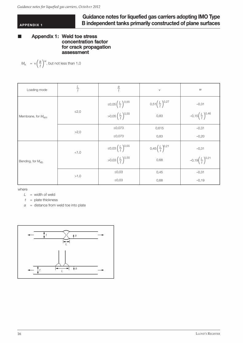
5.8.5 The next and last factor to be considered in thesecalculations is the additional stress concentration Mk due tothe weld toe, which is over and above those of geometricshape, misalignment and angular distortion. This factor is amaximum on the surface at the toe, and reduces to unity ata certain distance into the thickness. A simple model is touse Mk = 3 at the surface, reducing linearly to 1,0 at 0,15tbelow the surface. Where it is known that the welding is tobe of a high standard and is subject to 100 per cent NDE,the weld toe stress concentration factors as defined inAppendix 1 may be used. For example, sub-assembly panelwelds should normally be of this standard.
5.8.6 Where dressing of the weld toe is applied, areduced crack depth of 40 per cent of the original issuggested and Mk may be taken as unity.
5.8.7 Various values have been proposed for the materialconstants C and m, and for the threshold stress intensity ∆ Kth. The combination of these parameters may be takenfrom recognised standards. Lower bound values taken fromIIW recommendations [10] are given as follows for reference(in N, mm units):
C = 5,21E-13, m = 3 and ∆ Kth = 63 for steel; andC = 1,41E-11, m = 3 and ∆ Kth = 21 for aluminium;
C and ∆ Kth for nickel and austenitic stainless steels may beadjusted for material elastic modulus as per BS 7910 [13]extracted below:
C = 5,21 x 10–133and ( )
∆ Kth = ∆ Kth,steel ( )
5.8.8 Using these methods, crack growths can becalculated as for the fatigue analysis. Where propagation ofa crack over the second half of the thickness is predicted toproceed at a much faster rate than for the first halfthickness, improvement in scantlings and/or weld treatmentshould be considered.
EsteelE
EsteelE
5.8.9 Acceptable crack depth and length should beconsistent with the ‘leak before failure’ assumption behindthe Type B concept. Nominal values for design life areproposed in the appendix to this chapter largely based onreference [9] and accepted by Lloyd’s Register for previousApproval in Principle of Prismatic Type B tanks.
5.9 Leak rates.
5.9.1 The estimation of leak rates involves determiningthe crack size at the point of penetration through thethickness, growth of this during the subsequent 15 days,calculation of its open area and lastly estimation of the rateof leakage. All of these four stages require certainassumptions and therefore the resulting leakage can only beregarded as a general indication. Several rather complexmethods have been developed for this type of calculationand a summary of these is contained in Annex F to BS7910:2005. However a somewhat simpler approach isproposed herein, based on some early test data, from whichindicative leak rates can be obtained.
5.9.2 The following simplified procedure, although notrigorous in its individual parts, has been found to givereasonable results for design purposes. It is intended herethat the procedure is used as a whole, and therefore thatindividual components must not be substituted from othersources. In any event, the estimation of possible leakage is arather uncertain calculation as mentioned above, andconsequently high margins of safety are recommended tobe employed in the design of the partial secondary barrier. Adrip tray with sufficient capacity to contain at least five (5)times the calculated leaked cargo over the 15 day period inaccordance with IGC code has been adopted for sphericalType B tanks to built Lloyd’s Register class and this marginis recommended to be maintained for prismatic Type Btanks. For preliminary design purposes, a conservativeestimate of opening size may be derived from IACS GC9[19], assuming corner to corner crack on a bottom platepanel.
5.9.3 For determining the crack length on the initiatingside at the point of penetration a1, the crack limiting depth isto be taken as 0,8 of the tank thickness, when it is assumedthe crack may break through, due to the small remainingligament and the stress concentration on the opposite side.However, when the weld has been dressed on thepenetrating side, it is suggested that 0,9 of the thicknessshould be used. For this stage 1 calculation, either thestress or number of cycles is arbitrarily increased in order toforce penetration.
Guidance notes for liquefied gas carriers adopting IMO TypeB independent tanks primarily constructed of plane surfaces
LLOYD’S REGISTER 11
Guidance notes for liquefied gas carriers, Octob er 2012
Chapter 1SECTION 5
5.9.4 For the purpose of determining the crack growthafter penetration, the loading spectrum as specified by theGas Ship Rules [1] over 2 x 10⁵ response cycles is used.The starting crack size is given by the length as determinedfrom stage 1 and a depth equal to the shell thickness andthe crack growth constants are as before. From this stage 2,the crack length on the initiating side a, and on thepenetrating side a2 are computed at the end of 15 days.
5.9.5 The area of the crack opening A, when subjected toa mean stress σm , can then be estimated from the crackopening displacement d, and its half-length on thepenetrating side a2,i.e.
d =
and
A = =
In this stage 3 calculation, the mean stress may be taken asthe static membrane direct stress perpendicular to thepenetrating crack.
5.9.6 This, together with the orifice coefficient Cd, takenas 0,1, and the effective fluid head h’ is used to estimate theleak flow rate from
Q = Cd AHere the effective fluid head h’ is given by the head of fluidto the point of supposed leakage plus the over pressuredivided by the fluid density.
5.10 Weld preparation and treatment.
5.10.1 Where it is found that either:• the fatigue usage of a detail exceeds the criteria; or• a crack is calculated to penetrate more than the
maximum acceptable depth; or• the estimated leak rate is found to be unacceptable
for safe management;then post weld treatment may be considered in combinationwith suitable scantlings increase and/or local designimprovement. To maintain a minimum standard for thescantlings, the cumulative fatigue usage prior to consideringpost weld improvement should not be more than twice theacceptance values given in 5.7.
2g h’
2 π σm a22
E
π d a22
4 σm a2E
5.10.2 Post weld treatment would normally consist ofgrinding or dressing of the weld toes, or, in the case of buttwelds, this combined with flushing of the weld to remove itscap, or radiusing at a tee junction. These methods havebeen determined to be effective in reducing the stressconcentration caused by the weld profile, and henceincrease its fatigue life.
5.10.3 The first objective for all these treatments is toremove the sharp notch at the weld toe, together with allpossible undercut. It would normally be recommendedtherefore that the toe be ground to a smooth radiusextending into the parent material by a requisite depthsufficient to remove the toe flaw, but also ensuring no over-grinding. Sharp notches formed between adjacent beads ofa multi-run weld should be similarly treated. The secondobjective is to improve the weld surface shape, either byflushing or by radiusing. Radiusing is usually more frequentlyused, being normally recommended at the tee junctions toavoid severe stress concentrations. Additional detailedrecommendations are available from IIW recommendations[16] and Lloyd’s Register’s Fatigue Design AssessmentLevel 1 procedure document [26].
5.10.4 Where fatigue life improvement by post weldimprovement methods as described in Lloyd’s Register’sFatigue Design Assessment Level 1 procedure document[26] are considered, the improvement factors given in [26]may generally be applied. Other weld improvement methodsmay be specially considered. However, post weld fatigue lifeimprovement is not accepted where root cracks maydevelop and generally not accepted at the design stage inway of the following locations:• boxing fillet welds in way of the toe and heel of web
stiffener and bracket connections between primarymembers and secondary stiffeners;
• primary member bracket toes and termination ofprimary member face plate.
5.10.5 It may be noteworthy that a Shipbuilder with provenexperience building prismatic Type B LNG/LPG cargo tankshas utilised weld parameter control, e.g. flank angle and toeradius, as a means to achieve acceptable notch stressconcentration factors necessary to satisfy the crack initiationand propagation criteria and enhance the overall reliability ofthe containment system [7, 18].
Guidance notes for liquefied gas carriers adopting IMO TypeB independent tanks primarily constructed of plane surfaces
Guidance notes for liquefied gas carriers, Octob er 2012
Chapter 1SECTIONS 5, 6 & 7
LLOYD’S REGISTER12
5.10.6 It is considered admissible to take intoconsideration improved weld notch parameters in the crackinitiation and growth calculations, for example byintroduction of enhanced welding processes. Where weldparameter control is introduced into the design process, theconsistency and repeatability of the improved weldparameters is to be adequately demonstrated to thesatisfaction of Lloyd’s Register.
5.10.7 If weld grinding and/or weld profile control arespecified as a fatigue design feature, the details and methodof verification and recording are required to be documentedand approved by Lloyd’s Register, preferably as part of theConstruction Monitoring Plan [15]. More information isprovided in Chapter 7.
� SSeeccttiioonn 66:: FFaattiigguuee DDeessiiggnnAAsssseessssmmeenntt ooff hhuullllaanndd ttaannkk ssuuppppoorrttiinnggssyysstteemm ((FFDDAA))
6.1 General.
6.1.1 The fatigue strength for the hull structure isrecommended to be assessed in accordance with Lloyd’sRegister’s ShipRight FDA procedures incorporating theLevel 1, Level 2 and Level 3 approaches. Ships complyingwith the minimum requirement will be eligible for assignmentof the descriptive note ShipRight (FDA). In case morestringent fatigue design criteria are adopted, descriptive noteShipRight (FDA Plus) will be assignable. For details, pleaserefer to the document ‘Fatigue Design AssessmentOverview, August 2007’ [14].
6.1.2 ShipRight FDA: This descriptive note (FatigueDesign Assessment) will be assigned when an appraisal hasbeen made of the fatigue performance of the structure inaccordance with an agreed procedure between the Builder,Owner and Lloyd's Register, if requested by the Owner.Special consideration will be given to the assignment of FDAas a notation upon request.
6.2 FDA Level 1 – Structural Detail Design Guide.Detail design of structural connections in way of fatiguecritical joints should reflect industry best practice. Referencemay generally be taken from the FDA Level 1 StructuralDetail Design Guide [26].
6.3 FDA Level 2 – Longitudinal Stiffener EndConnections.The fatigue life in way of the longitudinal stiffener endconnections on the bottom, side, deck, inner bottom,hopper and inner hull should be verified in accordance withthe FDA Level 2 approach, choosing an appropriate shiptype template in the software.
The FDA Level 2 approach has been well established as afatigue design assessment tool for LNG carriers to Lloyd’sRegister class. The same approach can be applied withconfidence to liquefied gas carriers adopting prismatic TypeB independent cargo tanks.
6.4 FDA Level 3 – Cruciform Joints and Cargo TankBearing Seats.The fatigue life in way of potential critical locations such ashopper knuckles, deck transverse integration into the innerhull longitudinal bulkhead and cargo tank supports shouldbe assessed by a hot spot stress approach in line with theShipRight FDA Level 3 procedures document.
In lieu of the stochastic spectral approach outlined in theFDA3 procedures document, a simplified approach usingEquivalent Design Wave load cases will be acceptable forderiving the stress range for the hull bearing seats andchocks for the cargo tanks considering the contact problembetween the cargo tanks and the hull.
� SSeeccttiioonn 77:: CCoonnssttrruuccttiioonnmmoonniittoorriinngg ooff hhuullll,,ccaarrggoo ttaannkkssssuuppppoorrttiinngg ssyysstteemm((CCMM)),, aanndd ccaarrggoo ttaannkkss((CCTTII))
7.1 General.
7.1.1 It should be recognised that the accuracy of thecrack initiation and crack propagation calculations for anyType B tanks will depend to a large extent on theassumptions employed with respect to the constructiontolerances used to determine the stress concentrationfactors. To ensure the integrity of the cargo tanks in service,it is important that a systematic approach be adopted duringconstruction of the tanks to ensure that the tolerances staywithin the maximum allowed for in the calculations.
Guidance notes for liquefied gas carriers adopting IMO TypeB independent tanks primarily constructed of plane surfaces
LLOYD’S REGISTER 13
Guidance notes for liquefied gas carriers, Octob er 2012
Chapter 1SECTIONS 7 & 8
7.1.2 In this connection the Lloyd’s Register ShipRightConstruction Monitoring procedure [15] has been wellestablished amongst Shipbuilders as a means for theenhanced monitoring in way of fatigue critical locations forthe hull structure. It is considered that the CM proceduremay be employed for the cargo tank structure with suitableadaptation which may form part of the tanks’ Construction,Testing and Inspection (CTI) Plan.
7.1.3 The descriptive note ShipRight CM (ConstructionMonitoring) complements the Structural Design Assessment(SDA) and the Fatigue Design Assessment (FDA) and will beeligible to be assigned when enhanced controls inconstruction tolerances have been applied and verified inaccordance with the procedure.
7.2 Construction Monitoring (CM) Plan.
7.2.1 A construction monitoring (CM) plan will be requiredto be submitted to the Lloyd’s Register Design Supportoffice responsible for appraising the hull and cargo tanksupporting structure, together with the supporting strengthand fatigue calculations. The CM plan will be required toidentify the alignment method for all critical joints and theallowable construction misalignment for these joints, withremedial measures where appropriate. Where remedialmeasures are proposed, e.g. weld build-up and smoothdressing to compensate for larger than expected out-of-tolerance, its effectiveness is to be verified at the designassessment stage.
7.2.2 If weld grinding and/or weld profile control arespecified as a fatigue design feature, these are also to beclearly specified in the CM plan. Specification for weldgrinding is to include the allowable over-grinding to removeweld toe undercuts, required weld profile shape, grindingtool burr radius, etc. If weld profile control is specified, theweld flank angle and toe radius is to be specified, and themeans and extent of verification is to be suitably defined.
7.2.3 Extended controls on structural alignment fit up andworkmanship standards will be applied to areas of highstress concentration and fatigue criticality identified by thestructural design assessment and fatigue designassessment procedures. The CM procedure is to be appliedon a mandatory basis in conjunction with the mandatoryapplication of the SDA procedure and optional application ofthe FDA procedure, so as to ensure that the hull and cargotank supporting structure of the ship is designed andconstructed to an enhanced structural standard.
7.3 Construction, Testing and Inspection (CTI)Plan. Builders are required to submit a plan illustrating the tankerection sequence and method for verifying that seat andchock clearances are within design tolerances, andadjusting this clearance. This may form part of theConstruction, Testing and Inspection (CTI) Plan referred to inthe Gas Ship Rules paragraph LR 4.9-09 forming part of therequired approval documents for a liquefied gas carrier toLloyd’s Register class.
� SSeeccttiioonn 88:: MMaatteerriiaallss ooffccoonnssttrruuccttiioonn
8.1 The materials used in the construction ofindependent cargo tanks are to be manufactured and testedin accordance with the requirements of the Lloyd’sRegister’s Rules for the Manufacture, Testing andCertification of Materials. Materials for which provision is notmade therein may be accepted, provided that they complywith an approved specification and such tests as may beconsidered necessary.
Due to the effect of lower temperature cargo, this will affectthe material selection to parts of steel hull structures.Independent tank type B primarily constructed of planesurfaces requires insulation on the outer surface of the cargotanks.
Heat transfer calculations should be carried out to selectmaterial grades of hull steels in Table 6.5 of Gas Ship Rules[1].
Thermal boundary conditions for the heat transfercalculations, as defined by the Gas Ship Rules are:
Ambient still air temperature +5°CAmbient still water temperature 0°C
In addition, the temperature of the primary barrier is taken asthe minimum cargo temperature (–163°C in the case ofLNG), and the maximum predetermined design leakage atthis temperature into the drip pan forming the partialsecondary barrier is allowed for. The cooling effect of theevaporation of cargo from the secondary barrier in theprimary barrier breached condition is to be suitablyconsidered in the heat balance calculation.
Guidance notes for liquefied gas carriers adopting IMO TypeB independent tanks primarily constructed of plane surfaces
Guidance notes for liquefied gas carriers, Octob er 2012
Chapter 1SECTIONS 8, 9 & 10
LLOYD’S REGISTER14
8.2 U.S.C.G. Requirements for transverse andlongitudinal contiguous structure.
8.2.1 The U.S.C.G. require boundary conditions whichare the same as those above when considering the outerhull steel plating. However, for transverse and longitudinalcontiguous structure the following ambient conditions areapplicable:
Ambient still air temperature –18°CWind speed 5 KnotsAmbient still water temperature 0°C
Contiguous hull structure is defined as including longitudinaland transverse bulkhead plating, floors, webs, stringers andattached stiffeners.
8.3 Service in Alaskan Waters.
8.3.1 Should the capability for operation in Alaskanwaters be specified, then the thermal design conditionsapplicable are:
Ambient still air temperature –29°CWind speed 5 KnotsAmbient still water temperature –2°C
8.3 Similarly to the Rule conditions above, the primaryand partial secondary barrier temperatures are taken as theminimum cargo temperature (–163°C in the case of LNG)and include the allowance for the cooling effect of theevaporation of the liquefied gas which has leaked into thedrip tray(s).
� SSeeccttiioonn 99:: IInnssuullaattiioonn
9.1.1 Temperature distribution calculation should becarried out to determine the thermal insulation thickness forthe independent cargo tanks in accordance with Chapter4.8 of Gas Ship Rules [1]. The calculation should be basedon the cargo tank temperature of –163°C, the upperambient design temperature of 32°C for sea-water and 45°Cfor air and the lower ambient design temperature of 0°C forsea-water and 5°C for air, with due regard paid to theamount of acceptable boil-off rate.
9.1.2 Materials used for thermal insulation should besuitable for loads which may be imposed on them by theadjacent tank skin.
9.1.3 These should be tested for the following propertiesas applicable, to ensure that they are adequate for theintended service:• compatibility with the cargo;• solubility in the cargo;• absorption of the cargo;• shrinkage;• ageing;• closed cell content;• density;• mechanical properties;• thermal expansion;• abrasion;• cohesion;• thermal conductivity;• resistance to vibration;• resistance to fire and flame spread;• fatigue strength of welded attachments to the tank
skin;• fatigue strength of the tank skin in way of any welded
attachments.
� SSeeccttiioonn 1100:: RReeffeerreenncceess
[1] Lloyd’s Register’s Rules and Regulations for theConstruction and Classification of Ships for theCarriage of Liquefied Gases in Bulk, July 2010.
[2] ShipRight Structural Design Assessment – PrimaryStructure of Type B Spherical Tank LNG Ships, May 2004.
[3] Global Wave Statistics, British Maritime Technology,published by Unwin Brothers Ltd. 1986.
[4] US Coast Guard 46 CFR Ch. 1, Part 154 – SafetyStandards for Self-Propelled Vessels Carrying BulkLiquefied Gases.
[5] Lloyd’s Register’s Rules and Regulations for theClassification of Ships, July 2010.
[6] IACS Recommendation 34: Standard Wave Data.
[7] Production Process of Aluminum Alloy Tank of SPBLNG Carrier, Baba, O. Okumoto, Y. Abe, A., Journalof Light Metal Welding and Construction. 2007, VOL 45; PART 9, pages 26-35
Guidance notes for liquefied gas carriers adopting IMO TypeB independent tanks primarily constructed of plane surfaces
LLOYD’S REGISTER 15
Guidance notes for liquefied gas carriers, Octob er 2012
Chapter 1SECTION 10
[8] Results of ship-motion and stress measurement onSPB LNG carrier Polar Eagle. Nakajima, Y.; Shimizu, Y.; Abe, A.; Ito, A.; Ushirokawa, O. IHIEngineering Review (Ishikawajima-Harima HeavyIndustries Company); VOL. 28 ; ISSUE: 4 ; PBD: 1 Oct 1995
[9.1] The Shipbuilding Research Association of Japan;Committee RR3M, Report of Studies on IndependentPrismatic Tank Type B, Research Data No.68R,March 1978.
[9.2] The Shipbuilding Research Association of Japan;Committee RR3M, Report of Studies on IndependentPrismatic Tank Type B, Research Data No.78R,March 1979.
[10] Recommendations for Fatigue Design of WeldedJoints and Components, A. Hobbacher, IIW document XIII-2151r1-07 / XV-1254r1-07, May 2007.
[11] BS 5500 : 1997 Specification for Unfired FusionWelded Pressure Vessels, British Standards Institute.
[12] Fracture Mechanics Analysis of IndependentPrismatic Tank of Low Temperature LPG Carrier forVerification of IMCO Type B, Mitsubishi HeavyIndustries Technical Journal Vo.17 No.3. 1980.
[13] BS 7910: 2005 Guide to Methods for Assessing theAcceptability of Flaws in Metallic Structures, BritishStandards Institute.
[14] ShipRight Fatigue Design Assessment Overview,August 2007.
[15] ShipRight Construction Monitoring Procedure, May2004.
[16] IIW Recommendations on Post Weld Improvement ofSteel and Aluminium Structures, P. J. Haagensen andS. J. Maddox, XIII-2200r1-07, Revised July 2008.
[17] Improving Fatigue Life for Aluminum Cruciform Jointsby Weld Toe Grinding, Naiquan Ye, Torgeir Moan,10TH PRADS conference 2007 Houston USA.
[18] Fatigue Design Applied to A 5083-O/A 5183 StiffenedPlate Structure, Japanese Society of Naval ArchitectsSpring Lectures, May 1983.
[19] Interpretations of the IMCO code for the Constructionand Equipment of Ships carrying Liquefied Gases inBulk, International Association of ClassificationSocieties, 2008.
[20] ShipRight Structural Design Assessment – PrimaryHull and Cargo Tank Structure of Type A Tank LPGships, Guidance on direct calculations, May 2004.
[21] ShipRight Structural Design Assessment - SloshingLoads and Scantling Assessment, May 2004.
[22] Lloyd’s Register’s Rules and Regulations for theClassification of a Floating Offshore Installation at aFixed Location, April 2008.
[23] ShipRight Fatigue Design Assessment – Level 3Procedure, Guidance on direct calculations, May2004.
[24] Japanese Shipbuilding Quality Standards.
[25] Analyses of Surface Cracks in Finite Plates UnderTension or Bending Loads, J.C.Newman Jr, I.S Raju,NASA Technical Paper 1578, 1979.
[26] ShipRight Fatigue – Design Assessment Level 1Procedure – Structural Detail Design Guide,September 2009.
[27] ShipRight FOI – Floating Offshore InstallationsAssessment of Structures, Ship Units, Guidance onCalculations, April 2008.
[28] ShipRight Structural Design Assessment – PrimaryHull and Cargo Tank Structure of Liquefied GasCarriers Adopting Prismatic Type B IndependentTanks, Guidance on direct calculations, to bepublished.
Guidance notes for liquefied gas carriers adopting IMO TypeB independent tanks primarily constructed of plane surfaces
Guidance notes for liquefied gas carriers, Octob er 2012
Chapter 1APPENDIX 1
LLOYD’S REGISTER16
� AAppppeennddiixx 11:: WWeelldd ttooee ssttrreessssccoonncceennttrraattiioonn ffaaccttoorrffoorr ccrraacckk pprrooppaaggaattiioonnaasssseessssmmeenntt
Mk = νw, but not less than 1,0( )
whereL = width of weldt = plate thicknessa = distance from weld toe into plate
at
Loading mode
Membrane, for Mkm
Bending, for Mkb
≤2,0
>2,0
<1,0
>1,0
≤0,05 0,55( )
>0,05 0,55( )
≤0,073
≤0,073
≤0,03 0,55( )
>0,03 0,55( )
≤0,03
≤0,03
ν
0,51 0,27( )
0,83
0,615
0,83
0,45 0,21( )
0,68
0,45
0,68
w
–0,31
–0,15 0,46( )
–0,31
–0,20
–0,31
–0,19 0,21( )
–0,31
–0,19
Lt
Lt
Lt
Lt
Lt
Lt
Lt
Lt
at
Lt
a
L
t
aLt

Guidance notes for liquefied gas carriers adopting IMO TypeB independent tanks primarily constructed of plane surfaces
LLOYD’S REGISTER 17
Guidance notes for liquefied gas carriers, Octob er 2012
Chapter 1APPENDIX 2 & 3
� AAppppeennddiixx 22:: SSttrreessss ccoonncceennttrraattiioonnssdduuee ttoo ccoonnssttrruuccttiioonnttoolleerraanncceess
For misalignment between two plates of thickness t1 and t2of which t2 is the thinner, the stress concentration isobtained from:
KM = ( )where the eccentricity e is defined as
e = 0,5 (t1 – t2) + δmIt may be noted that when t1 = t1, the above reduces to
KM =
Similarly, for angular distortion
KD = + ( ) ( )whereA2 = x2 + y2
B2 = y2 – x2
x2 = 3 (1 – ν2) 2( )
y2 =
G = gauge lengthσA = mean tensile membrane stressE = modulus of elasticityν = Poisson’s ratio.
3 (1 – ν2)2G2Dt
Gt
σAE
6δdt
1coshA + cosB
sinBB
sinhAA
3et
t21,5
t11,5 + t21,56et2
� AAppppeennddiixx 33:: NNeewwmmaann--RRaajjuueeqquuaattiioonnss
For an elliptical surface crack of depth a, and half length c,the following equations apply:where
∆K = ∆σ.Y.
∆σ.Y =
in which∆σm is the membrane stress range, including the
stress concentration factor due to shape∆σb is the additional bending stress range at the
surface, including stress concentration factorsdue to both shape and construction tolerances
Mkm and Mkb are the weld toe stress concentration factors for
membrane and bending stress componentsφ is the elliptic function approximated by the
expressions below, and
F = M1 + M22+ M3
4fφ g fw[ ( ) ( ) ]
here for 0,0 ≤ ≤0,5:
M1 = 1,13 – 0,09
M2 = –0,54 +
M3 = 0,5 – + 14,0 1,0 – 24[ ( )]
g = 1,0 + 0,1 + 0,35 2 (1,0 – sinθ)2[ ( ) ]
fθ = sin2 θ + cos2 θ0,25[ ( ) ]
ϕ = 1,0 + 1,464 1,65 0,5[ ( ) ]
and for 0,5 < ≤1,0:
M1 =0,5
1 + 0,04 ( ) [ ( )]
M2 = 0,2 4( )
π a
ca
ca
ca
a2c
ac
ac
at
ac
1,0
0,65 +a[ (c)]
0,89
0,2 +a(c)
ac
a2c
at
at
[Mkm ∆ σm + H Mkb ∆ σb] Fφ

Guidance notes for liquefied gas carriers adopting IMO TypeB independent tanks primarily constructed of plane surfaces
Guidance notes for liquefied gas carriers, Octob er 2012
Chapter 1APPENDIX 3
LLOYD’S REGISTER18
M3 = –0,11 4( )
g = 1 + 0,1 + 0,35 2(1,0 – sinθ)2[ ( )( ) ]
fθ = cos2 θ + 2sin2 θ
0,25[ ( ) ]
ϕ = 1 + 1,464 1,65 0,5[ ( ) ]
alsoH = H1 + (H2 – H1) sinq θ
where for 0,0 ≤ ≤0,5:
q = 0,2 + + 0,6 ( ) ( )
H1 = 1 – 0,34 – 0,11 ( ) ( )( )
H2 = 1 + G1 + G22( ) ( )
G1 = –1,22 – 0,12 ( )
G2 = 0,55 – 1,05 0,75
+ 0,47 1,5( ) ( )
and for 0,5 < ≤1,0:
q = 0,2 + + 0,6 ( ) ( )
H1 = 1,0 – 0,04 + 0,41 + 0,55 – 1,93 [ ( )]( ) [0,75
+ 1,38 1,5 2( ) ( ) ]( )
H2 = 1,0 + G1 + G22( ) ( )
G1 = 2,11 + 0,77 ( )
G2 = 0,55 – 0,72 0,75
+ 0,14 1,5( ) ( )
The plate width correction factor is defined as
fw = sec 0,5[ (( ) )]a
tπcw
ca
ca
ca
at
at
ca
ca
at
ca
at
ca
at
a2c
ac
ac
ac
at
at
at
ac
at
ac
at
a2c
ca
ca
at
ca
ca
The above expressions are normally calculated for θ = 90° atthe bottom of the elliptical crack, for propagation throughthe thickness, and at θ = 0° for lengthwise propagationalong the surface.

Guidance notes for liquefied gas carriers adopting IMO TypeB independent tanks primarily constructed of plane surfaces
LLOYD’S REGISTER 19
Guidance notes for liquefied gas carriers, Octob er 2012
Chapter 1APPENDIX 4
� AAppppeennddiixx 44:: NNoommiinnaall aacccceeppttaanncceeccrriitteerriiaa ffoorr ccrraacckkpprrooppaaggaattiioonnaasssseessssmmeenntt
Primary members (Girder/Trans/Stringers)• Butt – up to 5 per cent of face area.• Slot – up to tank plate or 25 per cent to next
opening/slot.• Web stiffener – full depth.• Face in way of bracket toe – up to 5 per cent of face
area.• Bracket Toe – 25 mm.• Cruciform joint – penetration.• Web in way of face plate termination – 10 per cent of
web depth.
Secondary members• Stiffener – 25 per cent web depth.• Chock – face thickness.• Seat – 25 per cent web depth.
Tank boundary• 80 per cent plate thickness.

© Lloyd’s Register Group Limited 2012Published by Lloyd’s Register
Registered office71 Fenchurch Street, London, EC3M 4BS
United Kingdom

Document1 12/04/02 15:23 Page 1
ABCDLIFE MATTERS
Lloyd’s Register EMEA
T +44 (0)20 7709 9166F +44 (0)20 7488 4796E [email protected]
www.lr.org
71 Fenchurch StreetLondon EC3M 4BSUK
Lloyd’s Register ASIA
T +852 2287 9333F +852 2845 2616E [email protected]
www.lr.org
2nd Floor, Dah SingFinancial Centre108 Gloucester RoadWanchai, Hong KongSAR of PR China
Lloyd’s Register Americas, Inc
T +1 (1)281 675 3100F +1 (1)281 675 3139E [email protected]
www.lr.org
1330 Enclave ParkwaySuite 200HoustonTexas 77077, USA
Lloyd’s Register is a trading name of Lloyd’s Register Group Limited and its subsidiaries. For further details please see http://www.lr.org/entities