ship primary scantlings design & approval - nsrp · pdf fileship primary scantlings design...
TRANSCRIPT

Ship Primary Scantlings Design & Approval Product Design & Materials Technology Panel
An Experience Based Review of Issues Related to Primary Scantling Design and
Approval for Complex Vessels
National Steel and Shipbuilding Company Initial Design & Naval Architecture
Issued: September 2010 – Revision (-)
Catefory B - approved for public release; distribution is unlimited.

Page 2 of 88
Table of Contents 1. Executive Summary................................................................................................................. 3
2. Introduction ............................................................................................................................. 4
3. Characterization of Structural Features ................................................................................... 8
4. Design and Approval Requirements ...................................................................................... 13 4.1. Establish Requirements ................................................................................................. 15
4.1.1. Communication ..................................................................................................... 16
4.1.2. Shipyard and Owner Discussions .......................................................................... 21
4.1.3. Shipyard and Class Discussions ............................................................................ 26
4.1.4. Joint Discussions ................................................................................................... 28 4.2. Submissions to Class ..................................................................................................... 30 4.3. Class Review ................................................................................................................. 34 4.4. Post-Approval Issues ..................................................................................................... 37 4.5. Structural Design Process .............................................................................................. 37
5. Process Guide Framework ..................................................................................................... 40
6. Structural Rules Review ........................................................................................................ 42 6.1. Steel Vessel Rules Part 3 ............................................................................................... 42 6.2. Steel Vessel Rules Part 5 ............................................................................................... 44 6.3. Guides ............................................................................................................................ 47
7. Rules and Process .................................................................................................................. 50
8. Design and Analyses Tools and Methods.............................................................................. 51 8.1. Technical Software ........................................................................................................ 51 8.2. Plan Approval Management Software ........................................................................... 53
9. Conclusions ........................................................................................................................... 54
10. Further Work Recommendations ...................................................................................... 55
Appendix A - Structural Arrangement Features Template Examples ........................................... 56
Appendix B - Process Templates .................................................................................................. 70
Appendix C - Steel Vessel Rules Part 3 Primary Structure Requirements .................................... 84
Catefory B - approved for public release; distribution is unlimited.

Page 3 of 88
1. Executive Summary In recent years, U.S. shipbuilders and ship designers have been faced with the challenge of developing structural designs for complex vessels that comply with the requirements of National Classification Society rules.
Although there are comprehensive and sophisticated rule sets for standard vessels and special vessels, complex vessels fall under the ambit of the core rule set. This rule set, identified herein as the American Bureau of Shipping (ABS) Rules for Building and Classing Steel Vessels Part 3, is generally prescriptive in nature and is considered to lead to conservative scantlings when applied to unusual structural configurations and arrangements. In other words, “simple” ships are designed to complex, tailored rule sets and “complex” ships are designed to general rule sets. This is not necessarily an unsatisfactory situation; however, experience over the 15 years spanning 1990-2005 has shown that many programs encountered unanticipated challenges in achieving structural design approval on schedule.
The concept underlying this project is that by sharing this experience with the ship design and building community, some of the time-consuming issues identified and discussed can be prevented or mitigated through planning and preparedness. Hence, the target readership for this report is shipyard engineering managers and senior engineers involved in the structural design and approval process.
This report presents general commentary on issues related to scantling plan approval through a process map and discussion based upon direct experience. By presenting examples of structural arrangements and configurations encountered in complex vessels, a template approach to identifying requirements for design and approval within the context of the rule set is proposed. This set of examples is intended to form the initial input to a more comprehensive and extensive catalogue that can be developed in later phases of this project.
This report is specific to the requirements of ABS and its Rules at the time of writing; however, the general principles that are presented transcend the evolution and development of rules and organizational structures and methods. To that end, ABS has been an active participant in this panel project through the provision of advice and report review.
Catefory B - approved for public release; distribution is unlimited.

Page 4 of 88
2. Introduction This project was born out of primary structure design and approval experience accumulated from shipbuilding programs in which the outcomes were not as planned. These undesirable outcomes can be quantified in terms of budget overruns, schedule delay, or a combination of both. In some cases, the issues that emerged were traced back to failures to indentify and account for some aspects of the primary structure design development at a sufficiently early stage of material definition.
Consequences of such failures manifest themselves in terms of schedule delay and increased cycle time in various parts of the ship design and construction process. Schedule-threatening failures are not uniquely confined to the design and approval of primary structure; however, it is the timely material definition of this basic ship system that significantly influences the successful outcome of many successor activities. This is particularly true in the integrated 3-D product model environment used by most large shipyards to drive the production processes.
To support efficient product modeling, management demands that there be an acceptable level of data stability in the underlying design information. In practical terms, this means that there should be a high degree of demonstrable confidence that key vessel parameters and characteristics are fixed, and are accepted as fixed, by constituent parties. Among these key parameters are: vessel hull form, location of principal boundaries, and scantlings of constituent structural entities such as bulkheads, decks, girders, beams, and stanchions.
Achieving “demonstrable confidence” is a somewhat subjective concept, but aspects of design definition lend themselves to measurement to some standard that allows a confidence level to be expressed. For example, upon completion of all hydrodynamic investigations and the satisfaction of hydrodynamic performance requirements, hull lines can be declared “final” and production fairing can begin. Risk of change can then be stated as zero. In a similar vein, the completion of scantling design and review resulting in a documented statement of Class approval represents a “demonstrable confidence” waypoint in the structural material definition risk reduction path.
The relationship between change and design maturity is illustrated by Figure 1. This shows the impact on recorded instances of production related change associated with the planning and design state of maturity for three programs. Programs 1 and 2 are “design and build” whereas the third program is “build to print”. The former being one in which the shipbuilder prepares the design and the latter a mature, approved design is acquired from an outside source and adapted for shipyard construction.
The “design and build” data represent the experience between the first and second units of a program. In a multi-unit complex vessel program it is not unusual but undesirable to start the 2nd vessel with design and planning incomplete as indicated by the “design and build -1” example. The points of interest are the reductions in changes and production man-hours compared to the increase in the level of definition between ships 1 and 2 for both programs. In the case of the “build-to-print” program, the relatively small number of changes in the lead ship is striking. Although the changes reported are all trades and not just structural, the point remains valid.
Catefory B - approved for public release; distribution is unlimited.

Page 5 of 88
Figure 1: Change during Construction and Design Maturity
Ships vary greatly in complexity. Acquisition program approaches can overlay process and procedure complexity to the core technical process of establishing structural material definition in an orderly and timely fashion. As a result, it can be difficult to control the risk of change at a rate complementary to the rapidly expanding information needs of the production information timeline.
The goal of this project is to develop a process plan that will facilitate the design and approval of complex vessel primary structure within a timeframe that supports the ship construction schedule while also limiting the risk of primary structure change during the detail design and initial steel fabrication process.
A simple terminology is used for describing and discussing issues addressed in this report as follows:
• Owner – The entity that contracted the construction of the vessel
• Shipbuilder – The entity that contracted with the owner to design, build, and deliver the vessel
• Class – The entity that warrants that the vessel design and construction meet the regulatory requirements of the contract
• Material Definition – The process whereby the fabric of the ships structure is described in terms of material type, grade scantling, location, and orientation
• Product Model – A 3-dimensional computer-based representation of the content and spatial relationships of the vessel material
• Product Map – The compilation of all information required by Class to support plan approval
• Design-to-Build – A vessel acquisition program in which the vessel design is developed by the shipbuilder for construction in its facilities
Design & Build 1 Design & Build 2 Build to Print
Ship 1 Ship 2 Ship 1 Ship 2 Ship 1
More design and planning achieved by SOC Fewer changes during construction
Catefory B - approved for public release; distribution is unlimited.

Page 6 of 88
• Build-to-Print – A vessel acquisition program in which the shipbuilder acquires a proven design from an external source for construction in its facilities. In this scenario, although the design it may still need to be re-approved by Class.
In reality, relationships are rarely simple and each of the entities described above may comprise several organizations.
This work is based on U.S. experience and as such reference to Class is specific to the American Bureau of Shipping (ABS) and its Rules. While the examples are taken from project experience spanning a number of years, the rule citations and commentary refer to the ABS Rules for Building and Classing Steel Vessels 2010. It should be noted that Rules and Regulations evolve with time and it is incumbent on the shipbuilder to stay abreast of developments.
The experience base represented in this report derives from structural design and approval work on four shipbuilding programs undertaken between 1990 and 2005. The subject vessels are illustrated in Figure 2.
TOTE
2000-2003, 2 Ships
LMSR
1995-2000, 8 Ships
BP
2000-2005, 4 Ships
T-AKE
2001-2012, 14 Ships
TOTE
2000-2003, 2 Ships
LMSR
1995-2000, 8 Ships
BP
2000-2005, 4 Ships
T-AKE
2001-2012, 14 Ships
LMSR
1995-2000, 8 Ships
LMSR
1995-2000, 8 Ships
BP
2000-2005, 4 Ships
BP
2000-2005, 4 Ships
T-AKE
2001-2012, 14 Ships
T-AKE
2001-2012, 14 Ships
Figure 2: Vessel Programs
Catefory B - approved for public release; distribution is unlimited.

Page 7 of 88
Vessel characteristics are presented in Table 1.
Table 1: Vessel Characteristics
Characteristic Sealift LMSR Trailer Ship Tanker Dry Cargo
Owner Government Commercial Commercial Government
Type Vehicle Carrier Trailer Carrier Crude Oil Carrier Mixed Dry Stores & Bulk
Rules ABS SVR Pt. 3 ABS SVR Pt. 3 ABS SVR Pt. 5 ABS SVR Pt. 3
Structural Notations Yes No Yes Yes
Steel Weight (mt) 27,000 24,000 34,000 11,000
Cargo Weight (mt)/Type 20,000 /Mixed Ro-Ro 16,000 /Trailers and Autos 180,000/ Crude 12,000 /Mixed Dry
Cargo/Liquid
Catefory B - approved for public release; distribution is unlimited.

Page 8 of 88
3. Characterization of Structural Features This project addresses material definition issues associated with the design of complex vessel primary structure. In this context, “complex vessel” is understood to mean that the vessel is multi-functional and has an irregular operational cycle. This can be characterized by indicating what is not considered a complex vessel. Simply put, tankers, container ships, bulk carriers, etc. operate in a few operational conditions, carry a single homogeneous cargo, have repeatable structural arrangements through the cargo area, and are designed for a standard 25-year service life. Because they represent the greatest portion of the world’s trading and have been the subject of significant marine accidents, regulatory authorities and class societies have invested considerable effort in developing comprehensive rule sets that govern their structural design.
This is manifested in Rule sets such as the Common Structural Rules for Tankers, developed collaboratively by three class societies under the auspices of the International Association of Class Societies (IACS). A similar rule set is available for bulk carriers. In the case of ABS, specific rule sets for these ship types are included in the Steel Vessel Rules (SVR) Part 5 along with the Common Rules.
Complex vessels have few of the above features. They are more likely to be designed around special and diverse cargoes and may have multiple cargo handling routes, few repeatable structural arrangements, multiple operation scenarios, irregular operational cycles, and extended service lives. This concept is illustrated in Table 2.
Table 2: Rule Sets and Vessel Types
Non-Complex Vessels Complex Vessels
Ship Types Crude Carrier
Bulk Carrier
Containership
General Cargo Vessel
Rule Sets SVR Part 5 SVR Part 3
The structure of these vessels is generally designed to the requirements of Class rules, which in the case of ABS are the Steel Vessel Rules Part 3 (SVR Pt 3). This rule set provides the basic comprehensive scantling requirements for general cargo vessels and as such is prescriptive and conservative. These rules are those invoked by Owners for large steel-hulled vessels in the United States.
In general terms, the features of concern tend to be structurally extensive in scope and can be characterized in the following terms:
• Oversized openings penetrating main subdivision bulkheads
• Large sloped ramps or vertical opening penetrating multiple decks
• Large penetrations in shell side
• Open architecture loaded deck supporting structure and excessive spans
• Extensive structural discontinuities
• High ‘tween deck heights - deep supporting structures
• Integration of stiff and “soft” structures
To some degree, each of these features raises issues related to strength, structural stability (buckling), fatigue resistance, and vibration response. Although Class is actively
Catefory B - approved for public release; distribution is unlimited.

Page 9 of 88
concerned with strength, stability, and fatigue, vibration is generally a matter between the shipbuilder and the owner.
To provide a practical framework for the nature of structural arrangements encountered in complex vessels, a catalog drawn from recent ship design experience has been compiled. This sample catalog, which is included in Appendix A, illustrates the structural configuration and addresses the governing rules and design issues. The number of examples has been restricted for the purposes of this report. These are presented in no particular order. The structural arrangements and their features are summarized in Table 3.
Table 3: Examples of Structural Arrangements
SHIP STRUCTURE CHARACTERIZATION TEMPLATES
1. Large access doors through watertight bulkheads – sliding and overhead
2. Fixed access ramps penetrating through watertight decks and strength deck
3. Major side ports in side shell
4. Integration of large kingposts into primary structure
5. Extensive recesses in shell at sheer strake location
6. Extensive major discontinuities in mid-body
7. Stanchions supporting cargo carrying decks
8. Large openings in effective internal longitudinal structure
9. Bow flare and bottom structure arrangement issues
10. Load paths through loaded decks into double bottoms
11. Large fashion plate in critical location
12. Deep watertight bulkhead stiffeners in bending and compression
13. Large tanks subject to partial filling
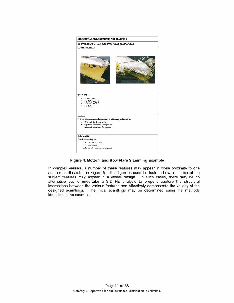
The proposed template and completed example are presented in Figure 3 and Figure 4.
The template illustrates the general characteristics of the structural arrangement feature through an illustration from scantling plans or Finite Element (FE) model extracts. There is no intended significance where FE model extracts are used for illustration purposes other than as a convenient way to depict the subject structural feature.
The governing SVR Pt 3 rule cites are identified and a short form identification of issues is provided.
An alternative approach to developing the scantling design using rule sets and or guidance other than Pt 3 is identified.
Catefory B - approved for public release; distribution is unlimited.

Page 10 of 88
Figure 3: Structural Arrangement Feature Template
To illustrate the form and presentation, an example using fore end bottom and bow flare slamming is shown in Figure 4. In this example, the Part 3 rules that would be used to size and arrange fore-end scantlings are identified. Issues arising from the relatively simplified prescriptive approach are presented in short form and the comprehensive Part 5 loads and scantling sizing requirements are identified as the recommended alternative method.
Catefory B - approved for public release; distribution is unlimited.
Page 11 of 88
Figure 4: Bottom and Bow Flare Slamming Example
In complex vessels, a number of these features may appear in close proximity to one another as illustrated in Figure 5. This figure is used to illustrate how a number of the subject features may appear in a vessel design. In such cases, there may be no alternative but to undertake a 3-D FE analysis to properly capture the structural interactions between the various features and effectively demonstrate the validity of the designed scantlings. The initial scantlings may be determined using the methods identified in the examples.
Catefory B - approved for public release; distribution is unlimited.

Page 12 of 88
Figure 5: Various Structural Arrangement Features in Close Proximity
Large Opening in Transverse Bulkhead
Large Opening in Longitudinal Bulkhead
Stiff Structure
Discontinuity
Sheer Strake Holes in Sheer Strake
Large Opening in Shell
Catefory B - approved for public release; distribution is unlimited.

Page 13 of 88
4. Design and Approval Requirements The key to a successful primary structure class approval process is the establishment of a common understanding of the requirements and expectation of the process outcomes among all participants. This requires an alignment of the expectations of all parties together with a clear definition of the rule sets and methods to be employed in the design of the vessel primary structure.
The process is illustrated in Figure 6 and addressed in generic terms as discussed in the following sections:
• Establishment of requirements
• Primary structure design
• Initial submission for class approval
• Class review
• Review response
• Incorporation of comments and resubmission
• Detail design development
• Management of approved submissions
Primary structure design is addressed separately in Section 4.5.
The intent underlying this section is to discuss various aspects of the design and approval process as outlined above with the purpose of sharing experiences and providing advice. A concern with setting this material down is that it appears to be so elementary that it is difficult to imagine that it is not universally known, understood, and practiced. Things do go wrong however, and root-cause analysis often shows that procedural failure as much as technical failure is a major contributing factor to an unplanned, undesirable outcome. This could be characterized as the “doing the wrong thing the right way” syndrome.
Catefory B - approved for public release; distribution is unlimited.

Page 14 of 88
Figure 6: Approval Process Framework – Primary Structure
Catefory B - approved for public release; distribution is unlimited.

Page 15 of 88
4.1. Establish Requirements In this phase of a ship acquisition program, the requirements, expectations, and commitments are established. There is an unstated relationship between the degree of bureaucratic sophistication on the part of the Owner and the complexity of the requirements process. This complexity can permeate its way into highly technical activities such as defining structural requirements in specification language. However complex or simple this process might be, it needs people representing the various program interests to communicate and agree upon a common set of requirements and methods to demonstrate compliance with the agreed-upon design requirements.
This element of the process should be complete prior to the principals entering into a binding contractual agreement. For the purposes of this discussion, the principals are understood to be the entity that has responsibility for the acceptance of the vessel and the entity that has responsibility for the timely delivery of the vessel, complete in all contractual respects.
Simplistically, these entities might be described as the Owner and the Shipbuilder. In these days of complex financing, multiple end-users, and program prime contractors supported by a myriad of sub-contractors, the Owner/Shipbuilder symbiosis is rarely a simple one-to-one correspondence.
The only advice to be offered in this respect is to ensure that constituents of the respective parties are clearly identified and the authority and responsibilities of each are clearly understood by all personnel involved in the program. The various participants and their particular interests as illustrated in Figure 7 are discussed below.
Figure 7: Establish Scantling Approval Requirements
Catefory B - approved for public release; distribution is unlimited.

Page 16 of 88
4.1.1. Communication Before discussing the participating parties and their interests, the central topic of communication is addressed as a process activity. In the following paragraphs, a few words of hard-earned wisdom are offered on this subject. From experience, it is noted that issues can arise due to communication failures of one sort or another. In this sense, an “issue” is considered to be an undesirable event that impacts the primary structure design and approval process. A few examples of such communication failures are illustrated in Table 4.
Catefory B - approved for public release; distribution is unlimited.

Page 17 of 88
Table 4: Communication Issues
Miscommunication Issue Outcome
Failure on the part of the Owner to identify all analysis cases “assumed” by the Owner
Upon completion of an extensive analysis the owner notes that a particular case has not been addressed. Class does not require the case
The shipyard agreed to run the case. In this particular situation no adverse findings resulted
Failure on the part of the shipyard to properly understand an Owner requirement which was incorrectly incorporated into the Specification
Upon completion of analysis Owner inquired about performance under dynamic loads.
Additional extensive analyses were undertaken which revealed non-compliance with specification
Failure of Shipyard to properly interpret Class “advice”
Shipyard had requested a pre-approval review of plans by Class with the objective of reducing the approval cycle time. The Shipyard chose to selectively incorporate Class “advice”
Increased plan approval cycle time and caused significant friction between Class and Shipyard
Failure to identify all requirements to achieve scantling approval of a complex mid-body structural design
The Shipyard engaged Class to undertake a pre-contract review and approval of a proposed design mid-ship section .6 months into the contract it was determined that a “direct calculation “ approach analysis would be required to support plan approval
An unplanned extensive 3-D finite element analysis was undertaken to support plan approval resulting in significant stress to both Shipyard and Class
The reaction at the time of realization and afterward when the shouting and finger pointing has stopped is usually, “how can this happen - we discussed this with the Owner/ Class/Etc. and we agreed.” Often the case is that we agreed to what we understood and the other party agreed to what it understood but neither party confirmed that they shared the same vision at the same time. Tedious as it may be in these matters, details such as number of load cases, ship conditions, acceptance criteria, design and analysis methods, representation of loads, etc. must be defined.
The examples are intended to illustrate how easily an unplanned event can arise even after extensive and seemingly comprehensive project preparation intended to avoid such communication breakdowns. When reviewing documentation and requirements, either with an Owner and/or Class, great care must be taken not to unilaterally assume the meaning or intent of a requirement. In particular, the Shipbuilder technical community must take care not to assume that because it has knowledge of the requirement from other project experience, this requirement may be satisfied in the same manner as before. The words may be similar but expectation may be quite different. Confirm the requirement and agree on how it will be satisfied with the other party.
The outcomes noted above were avoidable if the communication at the crucial point of failure had been sufficiently comprehensive and thorough. How to ensure that this communication represents a real challenge particularly in contract development stages of a project when there may be a measure of stress due to time constraints and nascent personal relationships between parties. Check sheets, compliance matrices, etc. are tools that might assist, but it is well to remember - if in doubt ask and no question is stupid.
Catefory B - approved for public release; distribution is unlimited.

Page 18 of 88
The initial interactions between the Owner, the Shipbuilder, and Class set the tone of the process and define the elements that will lead to its success or otherwise. Interaction between parties can be in the form of physical and virtual meetings, hard copy, or electronic media. Interactions can be among all parties at one session down to meetings between two participants.
From the perspective of all parties, it is important that communications are documented and stored such that they can be retrieved at any time within the program duration and beyond. At the very least, the record needs to capture the “who, when, and what” of the defined subject matter. Subject matter should be identified by reference to specification, design product, or rule citation as appropriate. Matters should not be agreed to orally without a documented record being filed. E-mail exchanges need to be retained and filed. Each entity must establish project-filing systems for the retention and management of project data and documentation and these should be used for record-keeping purposes. Regrettably, some issues are not resolved without resorting to contract claims or litigation. It is as well to note the maxim “if it was not written down it was never said”.
Another important aspect of communication is the identification of who within an entity has the authority to communicate and to what they can agree. This can range from agreeing to listen through to authorizing a specification change. Members of the various entities need to be aware of their own prerogatives and authority and when they are party to some discussion that leads to a decision, take responsibility for its documentation.
Topics that need to be addressed between entities are discussed below in a bilateral framework. Throughout the course of the requirements establishment phase of the process, it is customary that joint meetings take place involving all the participating entities. However there are a number of topics that are probably best settled between the Shipyard and the Owner and the Shipyard and Class before holding meetings with all participants. These topics need to be identified and agreement reached on the scope of discussions and the appropriate mechanism for reporting the decisions arising from the discussions.
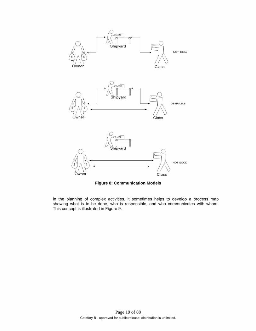
How communications are conducted is a matter for the participants to determine. In the ideal circumstances, communication should be open, keeping all parties informed or involved as needed on the subjects that are of importance to each. Some simple models are illustrated in Figure 8. Any general model that has two parties communicating to exclusion of the third is undesirable just as a model that has all communication going through a single entity is less than ideal. The risk is that focal point of communication may misrepresent the requirements of the other parties to each other.
Catefory B - approved for public release; distribution is unlimited.
Page 19 of 88
Figure 8: Communication Models
In the planning of complex activities, it sometimes helps to develop a process map showing what is to be done, who is responsible, and who communicates with whom. This concept is illustrated in Figure 9.
Catefory B - approved for public release; distribution is unlimited.

Page 20 of 88
Figure 9: Special Structure Analysis Process Map Showing Lines of Communication
This example illustrates the undertaking of a major special analysis in support of the award of an Owner-required structural notation. In this example, the Shipbuilder has chosen to have the analysis undertaken by a subcontractor using Class developed methods. The communication plan reflects the recognition that the Shipbuilder’s obligation to Owner only extends to providing the required notation and not making the Owner part of the process. In a similar manner, all communication with the analysis subcontractor is with the Shipbuilder. This model conforms to the “not ideal” model illustrated in Figure 8, and presented to show that compromise communication models might best serve certain circumstances. The message is that the Shipbuilder, who ultimately has contract responsibility, must determine the model that best serves its fulfillment of contract requirements. Irrespective of the particular model employed, communication must always be conducted with openness and honesty especially where bad news is concerned. Convey it quickly and succinctly accompanied by a work around plan.
In summary, experience has taught that good, clear, open communication between all participants is a key ingredient to the success of the scantling design and approval process. There will be difficulties, but all involved share the same objective of completing the activity to the agreed-upon schedule and delivering an approved scantling design in compliance with contract requirements. Although not the direct responsibility of the structural design community, attention should be paid to the provisions of the contract with a view to ensuring that the language does not inhibit free and open communication.
Catefory B - approved for public release; distribution is unlimited.
Page 21 of 88
4.1.2. Shipyard and Owner Discussions In the course of developing the shipbuilding contract between the shipyard and the owner, the shipyard structural engineering community is involved with the Owner’s technical representatives in the definition of the vessel structural requirements. Among the many topics that may arise, the following are considered the most important:
• Owner’s requirements
• Statement of work
• Shipbuilding specification
• Class rules and notations
• Structural standards and details
• Compliance demonstration
• Responsibilities and roles
These are addressed below:
Owner’s Requirements
In commercial practice this document is often quite modest in scope; however, some commercial owners may include a standard vessel specification or an outline specification with the requirements documentation. In the case of Government non-combatant programs, the requirements documentation invariably includes extensive and detailed performance documentation. From a structural design perspective particular issues need close attention. These include:
• Class and Rule sets
• Structural notations
• Vessel service life
• Owner specific structural performance requirements beyond Class requirements
• Vessel operational profile and operational area
• Wave environmental conditions
• Cargo loading conditions
• Specified design loads and stiffness/defection requirements
• Specific structural analyses required by the owner
• Owner corrosion allowances
These are discussed in the following paragraphs. The objective of this discussion is to share some topics that became issues late in programs due to a tacit acceptance of Owner’s requirements in the absence of sufficient technical due diligence during the requirements phase of program development. There is a fine line between reasonable due diligence and obstructionism and it is incumbent upon the Shipyard structural community to find its balance. There is also the risk of a form of technical hubris that arises when technical experts use “code words” to convey complex requirements rather than talk out the requirement in tedious detail. This can be described as the “this is what I want – I know what you mean” syndrome only to find out at some critical juncture in the program that what has been done is not what was required.
Generally, the Owner will identify the Class requirements with which it wishes the vessel to comply. In commercial acquisition programs the owner may identify a Class society with which the Shipbuilder does not have working experience. This is not the end of the
Catefory B - approved for public release; distribution is unlimited.

Page 22 of 88
world. Far Eastern yards are accustomed to having a standard design approved and constructed to requirements of a number of classification societies. The incorporation of International Association of Class Societies (IACS) unified rulings into member rules in recent years has lead to a measure of rule harmonization between national societies. If the Owner wishes to go in the direction of working with an offshore society, then the Shipbuilder would be prudent to initiate dialogue with the candidate society earlier than it might otherwise do in the case of the National society.
U.S. government vessels are designed and approved to the requirements of ABS rules and. For complex non-combatant vessels, the governing rule set is generally the Steel Vessel Rules Part 3. However these vessels may have RO-RO capability and/or capacity for limited amounts of mission dedicated bulk liquid fuel cargo and other features. Care must exercised to ensure that the vessel capability and mission is clearly defined and understood recognizing that the vessel maybe have to comply with other Rule sets in addition to the core Part 3 requirements.
In some cases, the carriage of bulk mission liquid fuel cargoes for example, compliance with the requirements of the Fuel Oil Carrier notation might appear appropriate. However this approach includes requirements for tankers that may not be necessary for the subject vessel. This is a case where the best approach might be to extract the desirable requirements from the subject Rule set and embed them into the requirements documentation for eventual inclusion in the ship specification.
Attention needs to be paid to notations requested by the Owner. Some, such as Dynamic Load Approach (SH-DLA), are structural and the in the case of structurally complex vessels can be time very consuming to obtain while others such as “Vehicle Carrier” include some structural design and analysis requirements that can be over looked. Before agreeing to the inclusion of notations, check the notation requirements to ensure that all structural design requirements are identified and confirm with Class what is required to be submitted to support notation award. Since many notations are optional, it is advisable to review the notation requirements and the Owner’s objectives to determine the reasons for requiring the notation in question. Then confirm with the Owner that the notation is really required.
ABS SVR Pt 3 Rules have 20 years service life implicit within the rule set; no specific requirement for fatigue life is identified. The conservative nature of these rules leads to scantlings combined with good detailing, for which fatigue is not an issue in general cargo vessels. However for complex vessels with service lives of over 25 years, the matter might be quite different. The intended operational service and service life required by the Owner must be understood by the structural design team. Any distinctions between structural service life and equipment service life need to be identified. Extended structural service life needs to be discussed with Class as there maybe associated design implications, such as increased wave bending moment due to a longer period of exposure to waves.
The treatment of fatigue life needs to be clearly agreed with the Owner. Operational area and vessel operating patterns need to be documented. For commercial-type vessels operating worldwide in regular service, this is a fairly straightforward matter. However if the vessel experiences periods of intermittent use with significant time along side or at anchor in sheltered waters combined with an extended structural service life, the need for fatigue analysis might be open to discussion. Generally, the North Atlantic wave climate with equal probability of waves from any direction is considered to represent Class standard but care has to be exercised as some trades can exhibit wave climate directionality; for example tankers operating between the US west coast and Alaska giving rise to localized fatigue failure patterns. Patterns arising from wave direction and vessel heading need to be identified and the resulting style of assessment and analysis planned for. Class can advise on this and can be a source of data and methodologies for undertaking non-standard analysis.
Catefory B - approved for public release; distribution is unlimited.

Page 23 of 88
A topic that occasionally arises is the request by the Owner for particular structural requirements and analyses that are not required by Class for scantling approval to be included in the specification. It is important that the requirements are fully understood and it is mutually agreed on how they will be satisfied, the criteria against which the results will be measured, and by whom satisfaction will be determined. In a similar vein, the Owner may advise that it is going to take responsibility for undertaking a structural analysis and delivering the results to the Shipyard for incorporation into the scantlings. This is the Owners prerogative and is acceptable however it does make the Owner part of the Shipyard scantling development process. The Owner needs to be made fully aware of this and educated in the Shipyard design and production processes affected by such an action. By adopting this position the Owner assumes risk not only to itself but also to the Shipyard. If this direction is proposed, the Shipyard structural design community must ensure that its management recognize this and appropriate contractual negotiations are conducted with the Owner.
A challenge with complex and multi-mission vessels is determining vessel-loading conditions for structural analyses. The effort should be made to address and document these as early as practical. Attention should also be paid to vessel partial load conditions and, in the case of dry cargo and vehicle carriers, partial loads in holds. It is recommended that Class should be consulted before agreeing to conditions included in the specification.
A topic with potentially significant primary structural implications is vibration response. Owners will usually identify structural response requirements in terms of a vibration standard, such as the ISO or ANSI standard and leave it at that. These standards provide response levels for habitability and work areas but do not address acceptable response from structural integrity viewpoint. Vibration is not a Class issue except for certain vessel types such as large container ships; however, major societies issue guides that can be useful in setting acceptance criteria for calculated and measured responses. This subject should be discussed openly with the Owner with a view to achieving an acceptable documented basis for assessing responses that exceed levels identified in the requested standard. It is recommended that the agreed basis is documented in some form or another by inclusion in the specification or some form of documentation such as a memorandum.
Corrosion allowances are incorporated into the Class rules; however, Owners sometimes require additional allowances in the form of increased scantlings. Particular attention must be paid to the exact definition of the extent of application of the allowance. Terms such as “bilges” need to be defined as does the application of the allowance to structural profiles and built-up sections. The allowance needs to be separately identified on scantling plans as this material is not included in rule scantling design and structural analysis.
Statement of Work
Some Owners develop comprehensive statements of the work to be undertaken in order to satisfy the requirements of the contract. These documents must be carefully reviewed by the Shipyard engineering community in order to ensure that work requirements that affect the conduct of technical activities are identified and taken into account.
A typical example of such an item could be the requirement to undertake a structural analysis using Owner specified loads and criteria. This is not necessarily a bad thing unless the requirement is missed and the analysis is not undertaken until late in the structural design process.
Any such requirements need to be identified and agreement with Owner should be documented with respect to purpose, scope, method, and criteria. If it is the Owner’s intention that the results be provided to Class, then the expectation must be established
Catefory B - approved for public release; distribution is unlimited.

Page 24 of 88
and Class advised of the investigation. In such cases, Class may review and comment upon the investigation report and advise that it is retained for file.
Class Rules and Notations
As noted above, when Class is identified the Shipbuilder and Owner need to agree on the Class Rule set to which the design will be approved. Class will advise on the effective date of Rules to be applied. The importance of establishing this date cannot be overstressed particularly in a period of significant Rule change as, for example, the introduction of the Common Structural Rules for tankers. The implications of misidentification of the appropriate effective date or Rule set can have commercial as well as technical implications. The structural design community has the responsibility to advise its management of issues that may arise with the agreed Rules. To this end, it may be beneficial to consider having a senior technical person as a member of the Class technical committee, thereby affording advance knowledge of proposed rule changes and providing a contact point for issues related to rule application.
Although notations have been discussed above under Owners Requirements, a few general points are worth reiterating. In particular:
• Recognize that some notations cover a broad range of system requirements beyond just structural. Read all the requirements thoroughly.
• Discuss the notation with Class to understand what is required in way of information to support the award of the notation. This extends to ensuring that proposed structural analyses are conducted in the required method.
• Discuss with the Owner to ensure that effort required in obtaining the notation is consistent with the Owners objectives.
Shipbuilding Specification
The development of the shipbuilding specification is probably the most intensive pre-contract technical activity that will take place between the Shipyard and the Owner. The good news for the shipyard structural engineering community is that the relevant specification sections tend to be few in number and quite brief. The bad news is that these requirements may represent Owners preferences based upon operational experience or other shipyard practices and standards. This tends to arise when working with Owners that operate internationally and procure vessels outside of the United States. Care has to be exercised to ensure that requirements that go beyond Class or are at odds with the specified Class or Shipyard standards and practices are identified and negotiated. The only advice to be offered is to take great care that all specification requirements are fully understood and that all the Shipyard organizations, particularly production, that are affected by the requirements, are involved in reviewing and agreeing to those requirements. Ensure that internal agreements are documented!
In situations where the Owner has a body of documentation and it is agreed to incorporate it into the specification, take care to ensure that the requirements are correctly and completely carried over and the incorporated requirements are contextually appropriate.
Structural Standards and Details:
Shipyards generally have their own standards and standard structural details that may be customized to meet the specific needs of the program. In reviewing and negotiating structural standards and standard details with the Owner, care has to be exercised by the Shipyard technical community. Steel product modeling and steel NC cutting, welding, and manufacturing issues arising from departures from Shipyard standards need to be identified and agreed upon within the Shipyard specialist community before agreeing to any change to standards and details. Although standard details must be submitted, Class is unlikely to attempt to impose “preferences” on the shipyard. Suggestions may
Catefory B - approved for public release; distribution is unlimited.

Page 25 of 88
be offered. Shipyard standards and details will have been reviewed by Class for other programs and should present no problems but it is wise to discuss with Class before new details are introduced and standards adopted. Examples of such details might include inner skin hopper joints in large wing ballast tanks and high fatigue life bracket toes in transverse webs. As noted elsewhere, SVR Pt 3 does not address fatigue requirements, so in cases of extended fatigue life requirements the Shipyard may find itself adopting proven details from other sources, such as a technology transfer partner. In such cases, Class and the Owner may require evidence of the suitability of the detail for the project application. This needs to be established and the form of suitability demonstration agreed at early as possible. In some cases, manufacturing process pilot demonstrations may need to undertaken. This needs to be identified and planned into the program. The definition of key structural details cannot be divorced from the design and validation of primary structure and this is particularly so in the case of complex vessel structure, bearing in mind that standards and details are at the heart of manufacturing processes and late-breaking changes can have major adverse impacts on the program schedule. This is a situation in which the details need to be sweated and as is often noted – “the devil is in the details”.
Compliance Demonstration
This is a topic that generally, for primary structures, should not present difficulties. However, the body of contact documentation needs to be reviewed to identify any specific compliance requirements. Where requirements are identified, ensure that the language and the expectations are clearly understood. Terms such as: verification, validation, certification, statement of fact, etc. may appear in specifications, contract, and statement of work documentation. In the context of structural design, confirm understandings with the Owner and document agreements. It is most important to identify what is to be demonstrated, how it will be demonstrated, objective criteria against which acceptance will be measured, who will arbitrate disagreements, etc. to name a few issues that need to be agreed upon. In particular, attention is drawn to Owner structural specification requirements in excess of, or not addressed by, Class.
For primary structure, Class approval and the award of required notations will suffice for demonstration of compliance. In the case of Owner specified structural requirements, matters may not be so straightforward. Invariably, when an Owner has unique structural requirements, apart from ship service dictated operational requirements, there may be an underlying concern related to the agreed rule set and its ability to adequately address some aspect of the structural design. It is important to fully understand the concern and establish how the concern will be addressed along with who will determine that the requirements have been met. Beware of Owners consultants and be equally cautious of methods that invoke the application of specific rules of other Class societies. Only those societies will review and comment on satisfaction of their rules.
Compliance demonstration also requires the management and maintenance of design data. The responsibility for compliance management resides with the Shipyard program manager; however, the structural design community will have to make its contribution to this activity. The implications of compliance management need to be taken into consideration by the structural design management team.
Responsibilities and Roles
The roles and responsibilities of those involved in the structural design and approval process should be clearly understood and agreed upon. Documentation by a simple organization chart can be helpful. In some cases, the Owner is not a single entity operating under a company name. The program Owner might be a partnership comprising a number of shipping companies with an operating entity quite distinct from the Owner. The differing experiences and opinions that this diversity brings to the project can be technically stimulating but great care must be taken to correctly identify who owns the structural requirements on the Owners side of the table and who will make decisions
Catefory B - approved for public release; distribution is unlimited.

Page 26 of 88
related to acceptability and completeness of structural design work. The danger is that at the working level, Shipyard engineering staff will undertake work based upon observations from a member of the Owner team which maybe out of scope or contrary to the Owner requirements. Equally, care must exercised in all dealings with the Owners consultants. More often than not the consultant is an infrequent visitor to the design activity and may possess an incomplete knowledge of the contact and a narrow view of requirements. Again the risk is that the Shipyard structural design team is deflected and goes off in unplanned directions. The mitigation is for the Shipyard management to ensure that its technical staff is fully aware of the program technical requirements and organizational prerogatives.
Related to roles and responsibilities is the subject of approval. With respect to scantlings, ABS will approve drawings for compliance with its rules; however, the Owner will have responsibility for signing off on its particular specification requirements. The term “signing-off” is used advisedly as specification and contract language can be confusing on this subject. “Owner Approval” is sometimes encountered and it should be detailed with respect to product and scope or extent. Generally, Class approves for rules and Owner approves for specification and this serves as a workable guideline. Another term that appears in this context is “review and comment” and deserves to be treated with caution. The term is not usually found in specifications and is more appropriately placed in the contract, where approval should also be found. From experience, there appears to be a subtle difference between “approval” and “comment”. In the approval environment, once approved, approvers do not subject subsequent revisions of the drawing or report to a complete review but rather check for the appropriate incorporation of approval review comments. Commentators, on the other hand, are just as likely to treat each revision as a first submission and offer comments on original content at the later submissions. A strategy for dealing with this is to classify comments with respect to their significance and agree that only critical ones will be addressed. Defining “critical” is essential to the success of this approach
4.1.3. Shipyard and Class Discussions At the earliest opportunity, preferably before contract signing, the Shipyard and Class must review and reach agreement on a number of topics related to structural design approval. These include:
• Vessel features and specification requirements
• Need for “special consideration”
• Applicable rules and guides including notations
• Information to be submitted
• Supporting calculations and analyses
• Communications and meetings
• Interaction prior to approval submissions
• Local approval
First and foremost in Shipyard and Class discussions the nature of the vessel and its technical and operational features should be fully disclosed, including any unusual specification and contract requirements. The objective is to avoid the future enlightening moments that intrude upon the parties’ individual perceptions of reality. Both parties need to work to ensure that there is a common understanding of the project requirements. The Shipyard can facilitate this by providing as much information as possible thus providing Class with the ability to fully appraise the demands the project will make upon its resources. It is recommended that preliminary information in the form of drawings, sketches, reports, specifications and requirements documentation are provided
Catefory B - approved for public release; distribution is unlimited.

Page 27 of 88
to Class as they are available. At this early stage, there is not a requirement for review; however, this should be made clear on all provided documents.
Any unusual or novel features of the vessel such B/D, L/B need to be discussed with Class. These may lead Class to determine that the vessel is subject to “Special Consideration” as noted at SVR 3-2-1/1. What this means in the context of the particular ship program needs to be established with Class and documented. In particular, if structural analyses are required to support scantling plan approval under a special consideration regime these analyses need to be identified and defined in extent and analysis methods at the earliest opportunity.
Invariably the rule set, its effective date, and any particular notations need to be established. Any particular project protocols, such as opting for an Alternative Compliance Program (ACP) needs to be determined. While not affecting primary scantling review and approval, Class does need to know if the Owner intends to opt for ACP and the Shipyard needs to fully understand the implications. The Rules to be used will be advised by Class based upon a key program date, generally the contract date for construction. As such this is not usually a matter of great concern for the structural design community other than to be advised of the Rule year which is being applied to the program. If there is a lengthy period between initial engineering activity and approval submissions the Rules employed in early design work and those applicable at the time of signing the Shipbuilding contract may differ by a year or two. It is as well to discuss prospective rule developments with Class along the way so that informed decisions can be made and surprises avoided. Owners will generally respond positively to pending rule changes and wish to have compliance incorporated into the design prior to the Rule effective date. Some changes can have significant structural implications such as the adoption of Common Structural Rules. In addition to the Rules to be applied and developments applicable to those Rules attention has to be paid to developments in other Regulatory codes such as IMO requirements. In the ACP environment, Class will advise on the status of proposed regulatory changes and the requirements for compliance. An example of a recent change with structural impact is the MARPOL requirement for keeping ships bunker off the shell. A requirement of that nature is much more easily designed into the vessel from the outset of design rather than retrofitted. Experience showed that Owners responded to the impending requirement 5 years in advance of the change effective date.
The subject of requested Notations has been addressed under Owner discussions and again the need to ensure that all the notation requirements are identified and understood cannot be overstressed. In particular if there are requirements for extensive finite element method structural analyses in support of notation award these should be discussed with Class in detail with respect to structural model extent, degree of mesh refinement, method of load derivation and application. Some notation requirements are straightforward such as SH-DLA however there are others which are not so obvious; examples of these are to be found in “Passenger Vessel” and “Vehicle Carrier” notation requirements. A further complication can arise when the Owner may have required a finite element global structural analysis with prescribed load cases and ship conditions in its requirements documentation while at the same time calling out a particular notation which has a FE analysis requirement imbedded. The Shipbuilder is advised to work with Class to tailor the specified analysis effort to satisfy the notation requirements. Try to avoid performing two separate analyses which cover similar areas. Even with the best of intentions, invariably comparison will be made between the results and more time and effort will spent trying to reconcile the irreconcilable – a truly no value added activity. Whatever the outcome of such discussions, the Shipbuilder is advised to agree and document with Class the plans, calculations and analysis reports which are to be submitted as the basis of review and award of the notation.
Much of the activity in the plan approval process can be thought of as an exercise in information management. The Shipbuilder provides the information which Class requires
Catefory B - approved for public release; distribution is unlimited.

Page 28 of 88
to enable it to review and approve the proposed design against a framework of the applicable Rules. In case of standard vessel structural design and approval this is a well-established data set and a reasonably straightforward activity. For structurally complex vessels the extent and scope of the structural design data set may not be well defined in the program early phases when the key parameters of Shipyard and Class contractual relationships are established. A danger is that while described in general terms of scantling plans and analysis reports the details are not only absent but also not understood. The Shipyard and Class need to work together to indentify the technical challenges represented by the design and map out what information is needed and how it will be presented. This information will reside in functional design scantling plans, calculation reports, analysis reports, structural standards, standard structural details, and construction key plans. It is recommended that required information and the information sources catalogued and form part of a Class Services Agreement. This catalogue is sometimes identified as a Product Map and is discussed in more detail at section 4.2.
Open and effective communication is considered to be a key contributor to successful structural design review and approval. A communication plan should be developed and agreed between the Shipyard and Class. Just as the Shipyard will have a project manager and quite possibly a project engineer, Class will identify a project manager and care should be taken that the project is set up in such a manner as not to impede technical communication at the working level. This can be achieved by setting out the key technical parameters of the contractual relationship such as work scope and applied methodologies and briefing the technical community, both designers and reviewers, on what is and is not within their authority. As part of the communication plan meetings should be addressed, however at the technical level between the Shipyard and Class these should be fairly informal and documentation need not go beyond and recording attendance, date, place, scope and decisions.
As part of Shipyard /Class discussions pre-contract interaction should be addressed. Some time can elapse between first contact and the signing of a construction contract which serves as the start point of official Class involvement in the Program. When dialogue between the Shipyard and Class is at a high level and confined to broad generalities Class may choose to treat this as a business development activity and it takes outside of any formal contractual agreement. When the Shipyard requires some specific support in advance of a construction contract, for example a review and comment on a proposed midship section concept, a contractual relationship may be required on the part of Class. Anticipated support from Class in the development of advanced technical proposal material needs to be identified and discussed with Class as early as practical
To wrap up this section on Shipyard/Class discussions it goes without saying that time spent going over the approval process is warranted. Some basic topics such as where and by whom review and approval will be undertaken needs to be addressed as certain flexibility may exist with respect to the actual office which will undertake the review. For example a Shipyard, as the contract prime may engage a design sub-contractor based in another part of the world. It may be possible to have scantlings submitted to the Class office in closest proximity to the scantling design sub-contractor if some benefit is obtained from taking that approach. Another aspect of approval is the recognition that following initial review and comment certain submissions in response to comments can be dealt with at a local level by the Class in yard surveyors thus greatly reducing the approval turnaround time. The procedures and prerogatives can be addressed well in advance to the benefit of both the Shipyard and Class.
4.1.4. Joint Discussions There is great benefit in having joint meetings with the Owner and Class; however, these should not be held until the Shipyard, Owner and Class have arrived at mutual
Catefory B - approved for public release; distribution is unlimited.

Page 29 of 88
understandings of the project. In practical terms, the timing of these meetings may be only a few days apart, hence do not need to represent a project delay.
The following need to clearly be established before going into meetings:
• Which entity is calling the meeting?
• Place of meeting
• The purpose of the meeting
• Who should be at the meeting?
• Individuals empowered to make decisions
• Which entity will prepare and distribute a record of the meeting?
Generally the Shipyard will call joint meetings; however, this maybe at the request of the Owner. Class will rarely call for a meeting but may well suggest that the project would benefit from some face-to-face coordination and communication.
Usually meetings with Class in which the Owner is present address topics related to analysis methods and interpretation of requirements. Bear in mind the issue of Class approval is usually one between the Shipyard and Class unless the contract has some very particular requirements. For example a notation for which the Owner is undertaking the supporting analysis and submitting it to Class for approval. These situations are fraught with opportunities for confusion and the importance of having a clear understanding of responsibilities cannot be overstressed.
Where a meeting is held is more an issue of convenience than contract requirement or protocol and in practice is often determined on the basis of least inconvenience to the majority of attendees. Another factor that plays into the selection of location is cases in which one organization may need a number of specialists for a short period of time each to deal with specific agenda items. It is recommended that consideration be given to using current electronic meeting technology – while pressing the flesh is good for team building it not always necessary that everybody be in the same place at the same time for a productive meeting or technical review.
Determining the purpose of the meeting in advance is of paramount importance. In addition to assuring the effectiveness of the meeting, it enables participants to prepare as necessary. Agreeing on the subject matter and scope can be done at the level of a few phone calls and e-mails, however, agreements should be captured in a written agenda with the date, start time, location, and planned duration identified in addition to the topics for discussion. Objectives should be stated such as: review and agree on load cases, identify and agree on end connection details, review results, etc. When appropriate, lead entities for each topic should be identified along with prospective attendees and their contact information.
Deciding who should attend a meeting needs to be given some thought, particularly for those entities attending from off-site. If the meeting is of a strictly technical nature, make sure that the required level and breadth of expertise is in attendance or at least conveniently contactable via e-mail, cell phone, or the fad of the day. If sub-contractors, whether they are working for the Shipyard, the Owner or Class are in attendance, make sure that they are provided with guidance on their role and prerogatives.
As with any effective and productive meeting, it should conclude with clear decisions related to the agenda topics. Make sure that the individuals who agree to actions and decisions arising from the discussion are empowered to make the decisions and have the support of their respective managements. This goes back to the agenda and who should attend the meeting. Even in a technical forum care has to be taken in the early stages of a project that as discussions stray into gray areas of ship specification, work scope and vessel performance agreements are not made at the working level which has contractual
Catefory B - approved for public release; distribution is unlimited.

Page 30 of 88
implications. While unauthorized excursions can usually be repaired, they are often accompanied by a degree of embarrassment, frustration and a loss of credibility.
On a final note in this section records of meetings need to be created and distributed to all attendees for agreement. Since the Shipyard more often than not calls the meeting it is usually acceptable that a Shipyard representative prepares and distributes a record of the meeting. This does not have to be a formal affair as often an e-mail to all attendees will be sufficient. Just remember on the Shipyard side to copy the project engineer so that management is aware of what was agreed and what commitments have been undertaken and assigned.
4.2. Submissions to Class The intent of this section is to provide some insight into the volume of structural information submitted to achieve Class approval of the scantlings of a complex vessel. Perhaps the two most pressing question to be addressed at the earliest phase of program are what needs to be submitted and when should it be submitted. A selection of the discussion topics is shown in Figure 10. As noted above, these are issues for the Shipyard and Class.
Figure 10: Submission to Class
ABS requirements for the submission of plans for review and approval are provided in Part 1, Chapter 1, Section 7. The listing provided indicates the structural features required to be submitted. It is the submitter’s (shipyard) responsibility to determine the format in which the required information will be submitted. The specific structural information is summarized in Table 5.
Table 5: Submission Requirements –Structural Information
• Anchor Handling Arrangement • Bow Framing • Framing Plan • Hull Port and Framing Details
When and What?
Catefory B - approved for public release; distribution is unlimited.

Page 31 of 88
• Machinery Casings • Boiler, Engine, and Main Auxiliary Foundations • Miscellaneous Non-Tight Bulkheads Used as Structural Supports • Scantling Profile and Decks • Shaft Tunnels • Skeg Attachment Foundations • Stem • Stern Framing • Ventilation System on Weather Decks • Watertight Doors and Framing • Welding Schedule and Details • Bottom Construction, Floors, Girders, etc. • Deck Plans • Hatches and Hatch Closing Arrangements • Inner Bottom Plating • Midship Section • Pillars and Girders • Shaft Struts • Shell Expansion • Spectacle Frames and Bossing Details • Stern Frame and Rudder • Superstructures and Deckhouses (with Closing Arrangements) • Watertight and Deep-Tank Bulkheads • Weather tight Doors, Framing, and Sill Heights • Window and Framing Details
In principal, many of the above features are included in the functional design scantling plans noting that the particular plans and their content will be determined by the shipyard practice and to some extent may be influenced by the vessel contract, specification, and statement of work requirements. The most important point for the shipyard is to work closely with Class to develop a clear and documented understanding of what will be submitted and how it will be presented.
For large complex vessels, the amount of structural information submitted is extensive and it may not all be shown on the functional design scantling plans that cover the complete vessel. Typically scantling plans show the structure by element such as decks, shell, sections, etc. each on separate plans. The most common set of scantling plans developed comprises shell expansion, midship section, structural sections, decks and profiles, and superstructures. This drawing package might typically comprise 80-100 sheets of “D” size drawings for a structurally complex vessel with little repeatable structure conveying technical information and represents the central part of a Class submission.
In the structural design and development process it is often the practice to create Zone key plans that show all the structural features and details such as shell, decks, frames, girders, bulkheads, brackets, chocks, lugs, etc. in one plan covering a part of the ship.
Catefory B - approved for public release; distribution is unlimited.

Page 32 of 88
Zone key plans show every component of structure defining its scantling, location, and orientation hence providing the input data to the structural 3-D product modeling activity. In the case of a complex vessel, the structure may be divided into 20-30 design zones and associated key plans comprise 800-1000 “H” sized drawing sheets, packed with a lot of structural detail information.
The Zone key plans are available too late in the scantling process to serve as the principal medium for plan approval. In addition, they represent too great a volume of information to serve the purposes of an efficient and timely structural design approval process. However they contain information required by Class to complete the scantling plan approval process. Experience has shown that it becomes an onerous chore to attempt to capture all the required information on the primary structure scantling plans.
To overcome this difficulty in some projects, specific extracts from key plans have been submitted in support of scantling plans to meet the information requirements noted in Table 5.
Table 5. The information submitted is derived from a matrix of Class submission requirement against structural design products. A typical list of structural design products for a large complex vessel would include:
• Scantling plans
• Rule based design calculation reports
• Finite element based global analyses of the vessel
• Finite element based local analyses of vessel parts and features
• Major equipment foundation analyses
• Standard structural details
• Structural welding details
• Design zone structural key plans
This body of information has been described as a product map and has been managed in a database or spreadsheet format. Generally, key plan extracts are used to provide required details for the following features which are not normally depicted on scantling plans:
• Foundations and backup structure supporting anchoring and mooring equipment
• Structural details of non standard (cargo) watertight door supports
• Details of Main Machinery foundations not shown in scantling plans
• Details of watertight hatch coamings and closures
• Life boat davit foundations and backup structure
• Lifting gear (such as monorails and bridge cranes) foundations, support structure and backup structure
• Bilge well and seachest structure
• Supporting and backup structure for heavy-duty appliances such as, cargo cranes, cargo transfer equipments, internal and external vehicle transfer ramps etc.
While the conventional functional design products listed above represent little challenge in packaging for submission, key plan extracts pose a different challenge. Key plan
Catefory B - approved for public release; distribution is unlimited.
Page 33 of 88
details of interest are rarely presented in a conveniently grouped standalone format. This is a fact of life that might be overcome by extensive presentation planning and drawing design. Providing selected complete key plan sheets with details of interest bubbled has raised problems for Class review control in the past. Similarly simple “cut and paste” presentations of a single detail or feature per sheet has been found to be less than satisfactory to Class. Some of the concerns relate to configuration identification issues and the tracking of such submissions in a comments database.
If it is planned to submit detail design information extracted from detailed structural key plans in the course of the structural design approval submission process, then it is recommended that the Shipyard and Class come to specific agreements on the format and style of these supporting submissions well in advance of the planned submission dates.
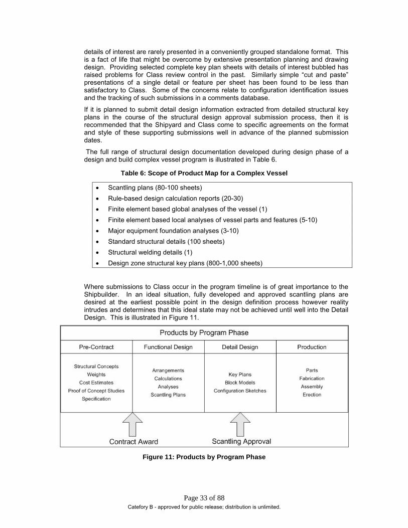
The full range of structural design documentation developed during design phase of a design and build complex vessel program is illustrated in Table 6.
Table 6: Scope of Product Map for a Complex Vessel
• Scantling plans (80-100 sheets) • Rule-based design calculation reports (20-30) • Finite element based global analyses of the vessel (1) • Finite element based local analyses of vessel parts and features (5-10) • Major equipment foundation analyses (3-10) • Standard structural details (100 sheets) • Structural welding details (1) • Design zone structural key plans (800-1,000 sheets)
Where submissions to Class occur in the program timeline is of great importance to the Shipbuilder. In an ideal situation, fully developed and approved scantling plans are desired at the earliest possible point in the design definition process however reality intrudes and determines that this ideal state may not be achieved until well into the Detail Design. This is illustrated in Figure 11.
Figure 11: Products by Program Phase
Catefory B - approved for public release; distribution is unlimited.

Page 34 of 88
In the pre–contract phase indicated in the figure above, the Shipyard and Class can benefit from early engagement to the extent that preliminary submissions can be made that provide Class with the opportunity to gain an understanding of the vessel design and provide advice to the Shipyard. In doing so, the purpose of the submission and its status needs to be clearly stated so that expectations related to subsequent submissions are realistic and the significance of the activity is not misrepresented.
4.3. Class Review Having prepared and submitted its scantling plans, supporting calculations, and analyses the shipbuilder can sit back and eagerly await response from Class. The often leads to the well-worked response to the project manager when inquiring why certain drawings are late: “waiting for Class comments,” which is often translated into “Class is late”. At this point, the Shipbuilder/Class relationship may deteriorate into acrimony that increases in intensity as the issue elevates its way through the respective organizational hierarchies. It is an objective of this panel project to avoid the occurrence of this unplanned and useless activity.
To aid this, the Class review process is discussed and lessons learned identified. The discussion is framed within the topics noted at Figure 12. As noted above in section 4.1.3 it is considered effort well spent in going through the review and comment process in some detail at the earliest opportunity with Class.
Figure 12: Class Review Topics
The focus of the Class review process is centered on the approval of the scantling plans. In the case of ABS, plan approval reviews are conducted in the framework of specific internal process instructions. These process instructions identify the scope and responsibilities in addition to detailed rule requirements with reviewer guidance and advice. At the time of writing this report, ABS had some 50 specific technical internal process instructions of 15-20 addressed topics directly applicable to the approval of vessel primary structures. The subject matter of these process instructions are listed in Table 7.
Table 7: ABS Process Instruction - Subject Matter
• Steel Vessels – General • General Cargo Vessels • Oil and Fuel Oil Carriers/MARPOL • Container Carriers • Container Securing and Lashing • Longitudinal Strength
Catefory B - approved for public release; distribution is unlimited.

Page 35 of 88
• Bow, Stern, and Side Doors and their Securing • Profile & Decks • Hatch Covers • Welding – Hull • Review of Miscellaneous Structural Plans • Cargo Hold Construction • Engine Room Construction • Aft End Structure • Superstructures and Deckhouses Construction • Bow Construction
It needs to be appreciated that Class approves designs upon the basis of compliance with the pertinent Rule requirements and how these requirements are addressed in submitted drawings. Ideally, Class comments should be linked to Rule citations as this makes the reason for the comment clear and unambiguous. In dealing with comments related to SVR Pt 3 compliance, this is particularly important as that Rule set is full of general requirements and admonitions. This is touched upon further in Section 6. If the reason for the comment is not clear, do not hesitate to seek clarification from Class. Never assume a reason for a comment and prepare a response without first discussing the comment and the proposed response with Class. Do not be reluctant to challenge a comment if the basis for the comment is unclear or unspecified. Take care to ensure that such actions are executed in a professional, neutral, and objective manner with all communications between the Shipyard and Class being documented.
Class comments will be conveyed by letter and entered into a Class database to facilitate tracking. The Class letter may state that the drawing is approved subject to the satisfactory closing of all the comments. What this means from the Shipyard perspective is that the process is not complete until all comments are resolved to the satisfaction of Class.
Some comments may be identified as Surveyor comments and this means that it will be up to the onsite surveyor to give the final disposition. Comments of that nature usually relate to the physical implementation of noted detail features of the structural design. It is the Shipyard Engineering responsibility to ensure that the feature is correctly represented in the production information and Shipyard Production to ensure that it is correctly implemented. The Class surveyor will inspect and pronounce satisfaction thus closing the comment. This will happen long after Start of Construction; however, such comments are not normally regarded to represent program risk since there is no associated technical uncertainty.
Reports of calculations and analyses submitted in support of plan approval are also subject to review and the comments arising from these reviews will be relayed to the Shipyard. These comments need to be addressed and responded to in the same manner as plan comments.
How plans, reports, and comments are transmitted and controlled has varied through time and can be expected to change in the future. Currently, Class (ABS) accepts electronic submissions and responds by letter and drawing mark-up in electronic form. The current ABS system is known as My Eagle, which is briefly described in Section 8. As noted above, Class will provide the Shipbuilder with support in fully understanding and becoming familiar with its use. In addition to plans and reports, comments and associated responses are logged and tracked in the system
Catefory B - approved for public release; distribution is unlimited.

Page 36 of 88
The approval process is not complete until all Class comments have been satisfactorily answered. The process of responding to comments can become a project in its own right. The most effective strategy is to avoid generating Class comments or at least minimize them and contain their severity to minor rule infractions. Although Comment avoidance strategy is the objective of this project, it is inevitable that comments against scantling plans will be received and that being the case it remains to determine how best to mitigate their impact upon ongoing design development work.
Elements of the Class review comment response are illustrated in Figure 13.
Figure 13: Class Comment Response Phase
The above figure illustrates issues that arise in dealing with Class comments and these are discussed in the following paragraphs.
Responses to Class comments can cover the full range of submissions from a brief letter to a plan or a detailed report of extensive analyses. The response will be a formal response to a specific numbered review comment and as such considered as a submission. As noted above under Class Discussions (Section 4.1.3) some comments can be dealt with at the local level on site with the survey staff. These are not to be confused with Class surveyor comments. Local approvals are usually based on the submission of engineering change notices (ECN) and are logged and disposed within the Class review management system in the same manner as Headquarter submissions. Surveyor comments are comments identified in the course of Class review which are designated for local disposition due the construction issue raised rather than design issues.
Shipyard engineering organizations usually have procedures governing the incorporation of ECNs resulting in drawing reissues. ECNs will record change from a number of sources such as design development, Owner comments, error and omission correction and response to Class comments. These reissued drawings will be submitted to class and be subject to the review and approval cycle in the same manner as the original issue. For the structural design community all that can be advised about this is to exercise diligence in keeping Class advised of developments and be aware of the contents of the Shipyard/Class plan approval services agreement. Typically the Class work scope is developed at the at the program level at time well in advance of design development and in the absence of a sound appreciation of structural design complexities and issues. A standard first issue with one revision may agreed to which as the design develops may be found to be seriously inadequate.
Note that the Owner box in figure 13 is empty. This is as it should be when discussing Class approval. The role of the Owner in the approval process is governed by the contract and possibly the ship specification. In ideal circumstance the universe of
Catefory B - approved for public release; distribution is unlimited.

Page 37 of 88
approval activity neatly breaks down into Class reviewing for rule compliance and the Owner reviewing for specification compliance. In the structural review and approval process Class is invariably the only regulatory authority reviewing the structural design thus making the review system binary and if there are no specification structural requirements above and beyond Class rule requirements then Class becomes the only reviewing and approving agent. Owners tend to focus their interest and involvement on the arrangement of details as they may appear in construction key plans for example. However when owners retain a third party (a consultant) to review scantling plans the Shipyard can anticipate numerous comments some of which may relate to rule requirements. Do not respond to these comments but rather refer them back to Class for a response. Never attempt to interpret Class rules for the benefit of others. Class will be quick to inform the unwary and inexperienced that only Class interprets Class rules. Any such efforts will only result in confusion and unhappiness all round.
An interesting approval issue arises when there are program requirements, usually Owner generated for scantlings to be determined in accordance with Class rules other than those of the approving Class organization. For example the vessel scantlings may be designed to ABS rules for approval by ABS while local structure such bow flare and bow bottom structure are required by the owner to be designed in accordance with other Class rules such as DNV and LR Yes this has happened, and the first advice based upon experience is do not agree to the requirement – you end up with the worst of all worlds. The second advice is make it very clear to the other reviewing Class or Classes exactly what is the expectation. The approving Class will only confirm that the scantlings meet its requirements or not and make no further comment other than to identify non-compliance against its rules. The other Classes may express strong reservations about stating approval of the subject local scantlings and at the best may offer review and confirmation that the calculations have been correctly done. The Owner needs to understand what is being offered and agree to accept this in its approval process. This may seem to be a fine point but Classification organizations are very particular about they approve and the associated liability which goes with granting approval. To the case in point the other Class organizations would not review the plans which depicted the scantlings but rather checked the scantling calculation reports.
4.4. Post-Approval Issues Successful achievement of plan approval is not necessarily the end of the process. As detail design proceeds, the need for structural change may arise. In reality, even during vessel construction, structural changes can take place, perhaps as consequence of a late breaking-analysis or a creative interpretation of information by production. No matter the cause of the change, if it resided in an approved plan, then the change needs to be approved. Although not a technical issue per se, care has to be exercised in recording and managing post-approval change. This requires time and effort and, in some cases, may require supporting technical effort in the form of analysis to ensure that the scantlings remain “approved”.
4.5. Structural Design Process A simplified representation of the primary structural design process is illustrated in Figure 14.
Catefory B - approved for public release; distribution is unlimited.
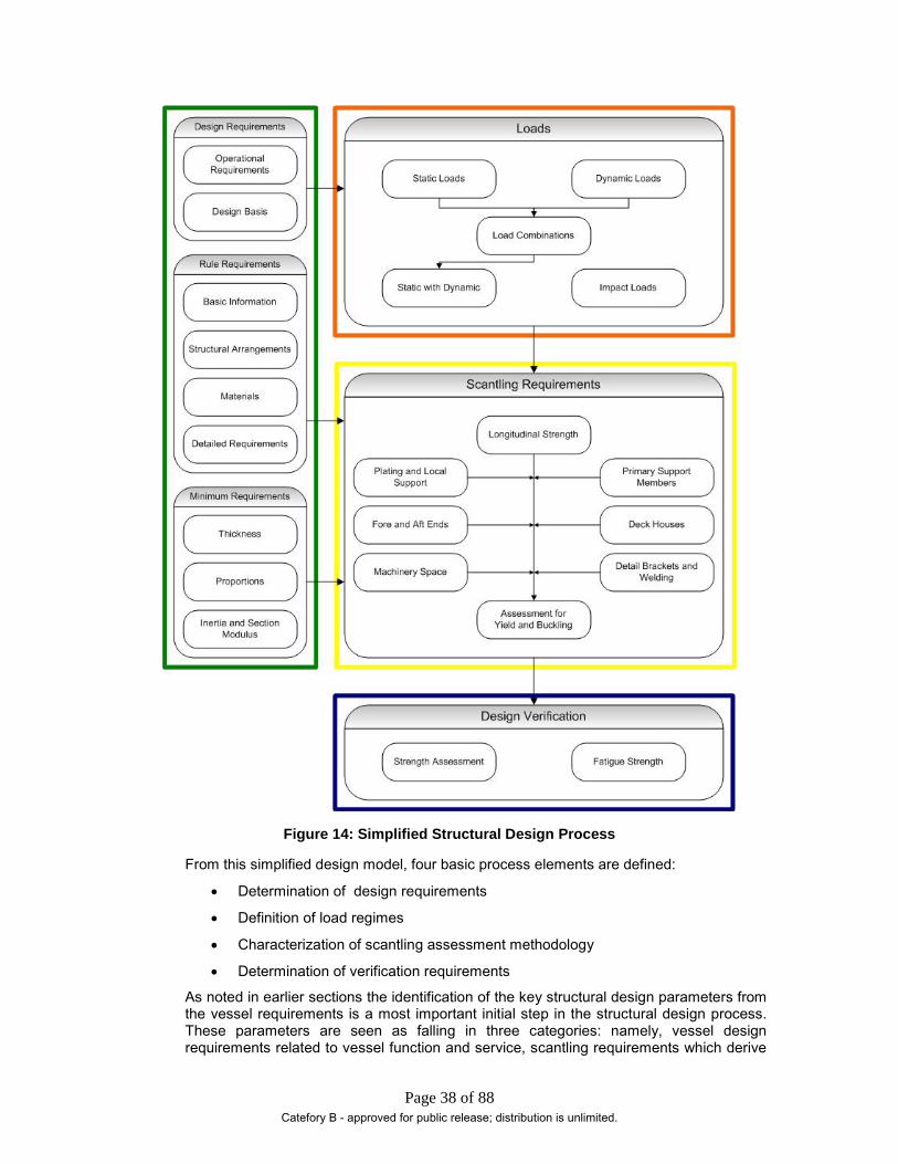
Page 38 of 88
Figure 14: Simplified Structural Design Process
From this simplified design model, four basic process elements are defined:
• Determination of design requirements
• Definition of load regimes
• Characterization of scantling assessment methodology
• Determination of verification requirements
As noted in earlier sections the identification of the key structural design parameters from the vessel requirements is a most important initial step in the structural design process. These parameters are seen as falling in three categories: namely, vessel design requirements related to vessel function and service, scantling requirements which derive
Catefory B - approved for public release; distribution is unlimited.

Page 39 of 88
from the applicable Rule set and mandatory minima embedded in the applicable rule set , such as thickness ,section modulus etc.
While the relatively simple prescriptive rules of SVR Pt 3 take the designer from the requirements definition to scantling determination without explicitly addressing load regimes and combinations of loads, the Pt 5 Rules address static and dynamic loading combinations for primary scantlings. This direct approach reflects the approach of classical structural mechanics in which operational loads are applied to a structural model to derive structural performance measures such as strength and stability which can be compared to established acceptance criteria.
This load determination function is illustrated in red box of the process diagram. In the SVR Pt 5 load model, rule based formulations are provided for global still-water and wave-induced bending and torsional moment. Wave-induced internal and external loads are accounted for as are slamming, impact, and cargo loads.
Derived load regimes applied to the vessel structural configurations at a global level and as appropriate, the local level will result in scantlings for the vessel mid-body region and the parts of ship as indicate in the diagram.
Having determined initial scantlings the adequacy of the structural configuration and these scantlings is assessed against specified failure criteria. Invariably for structurally complex vessels the assessment is conducted through the medium an extensive 3-D finite element model applying either direct calculation loads or representations of Rule defined loads acting in prescribed combinations, In this process element, indentified as validation, The structural members are checked for compliance with yielding, buckling and ultimate strength criteria. Details and connections may be checked for fatigue life depending upon the vessel operational requirements and declared service life.
This simplified design model is used as the framework for process template described in Section 7.
Catefory B - approved for public release; distribution is unlimited.
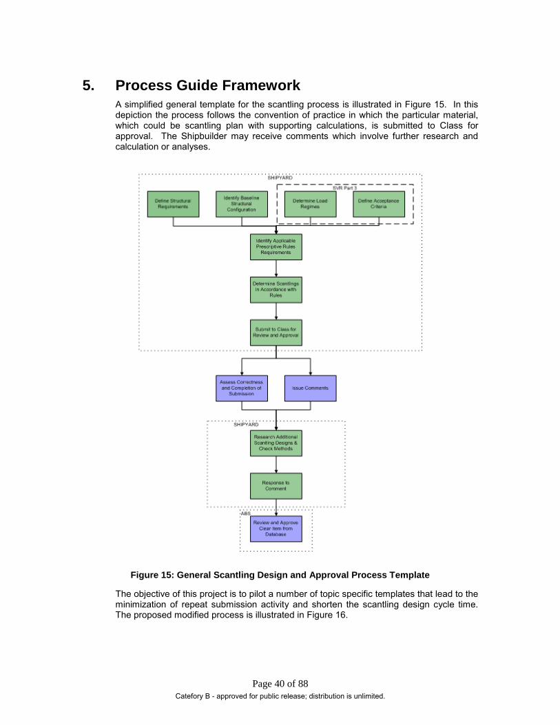
Page 40 of 88
5. Process Guide Framework A simplified general template for the scantling process is illustrated in Figure 15. In this depiction the process follows the convention of practice in which the particular material, which could be scantling plan with supporting calculations, is submitted to Class for approval. The Shipbuilder may receive comments which involve further research and calculation or analyses.
Figure 15: General Scantling Design and Approval Process Template
The objective of this project is to pilot a number of topic specific templates that lead to the minimization of repeat submission activity and shorten the scantling design cycle time. The proposed modified process is illustrated in Figure 16.
Catefory B - approved for public release; distribution is unlimited.
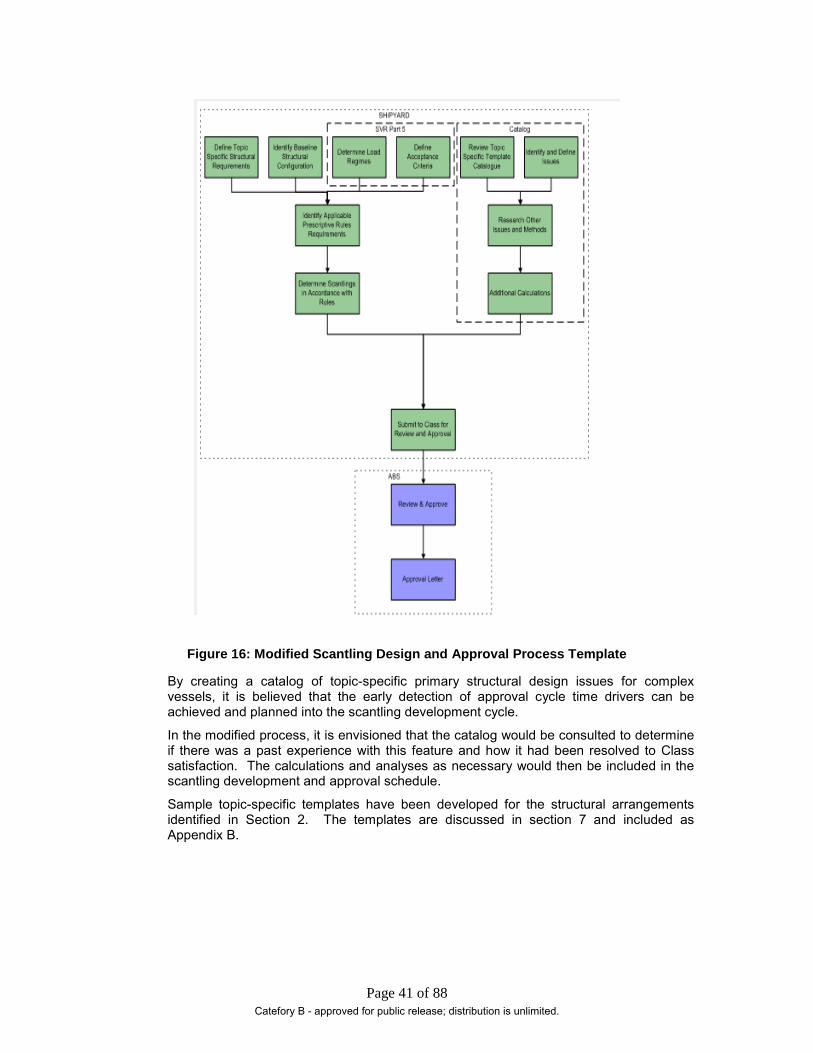
Page 41 of 88
Figure 16: Modified Scantling Design and Approval Process Template
By creating a catalog of topic-specific primary structural design issues for complex vessels, it is believed that the early detection of approval cycle time drivers can be achieved and planned into the scantling development cycle.
In the modified process, it is envisioned that the catalog would be consulted to determine if there was a past experience with this feature and how it had been resolved to Class satisfaction. The calculations and analyses as necessary would then be included in the scantling development and approval schedule.
Sample topic-specific templates have been developed for the structural arrangements identified in Section 2. The templates are discussed in section 7 and included as Appendix B.
Catefory B - approved for public release; distribution is unlimited.

Page 42 of 88
6. Structural Rules Review In this section, the principal rule sets are reviewed and discussed in the context of identifying features of interest that pertain to complex vessels within ABS SVR Pt 3 and Rule scantling assessment methods outside of ABS SVR Pt 3. Pertinent ABS guides are also identified and discussed.
Class rules are subject to an ongoing review and development process based upon industry feedback, surveyor input, and marine structure research, which through a committee process leads to rule change and expansion to address current needs. The following notes are based upon the ABS 2010 Rules and as such will become dated. The importance of staying abreast of current rules within the structural design community cannot be overstressed.
6.1. Steel Vessel Rules Part 3 Part 3 of the Steel Vessel Rules represents the original and most basic rule set addressing the design of ship structures that are of interest to Class from the viewpoint of approval. SVR Pt 3 covers a wide range of topics including structures, subdivision, stability, fire safety, deck equipment, and visibility. Implicit in the part 3 rules is the assumption of 20-year service life with 85% vessel utilization. It is to be noted that there are no explicit requirements for fatigue strength or assessment methodologies prescribed in this rule set
SVR Pt 3 comprises 7 chapters of which only chapters 1, 2, and 7 are of specific interest to scantling design.
Chapter 1 provides definitions of principal dimensions to be used in the formulae contained in other chapters and sections of the rule set. In addition to presenting steel material requirements, chapter 1 also provides overarching general requirements for scantlings and details. Note that detail requirements for steel material are contained in SVR Part 2 Materials and Welding. The general requirements for scantlings, proportions, structural sections such as angles, channels, bulbs etc design details and need to be very carefully read within the context of the subject project. Within design details reference is made to the ABS publication “Guide for Shipbuilding and Repair Quality Standard for Hull Structures during Construction”. This guide which is the ABS version of the IACS requirements can be used as the basis of the shipyard construction standard. While not directly affecting primary scantling design, structural designers should be aware of its contents.
Of the 19 sections in Chapter 2, 15 are of significance to primary scantling sizing.
Section 1 provides the requirements for hull girder modulus taking into account a prescriptive assessment of wave bending and shear which is additive with the still water values for vessel conditions of interest. Scantlings are determined on the basis of a nominal permissible bending stress. The resulting scantlings are maintained over the mid-body 0.4L. Appendices are also included which provide methods for the assessment of elastic buckling in longitudinal structure and the calculation of shear flow around closed a section. ABS provides a software routine, Hull Girder Shear Assessment (HGSA), to facilitate the calculation of nominal shear stress taking account of shear flow. The results of this key analysis are presented in the longitudinal strength assessment report. While seeming to a simple calculation in reality the report can represent a substantial body of work for a structurally complex vessel with a significant number of possible loading conditions. The volume of effort is compounded by need for assessment at numerous sections along the length of the vessel, determined by lack of regularity of the vessel transverse structural arrangement. The greatest challenge with this analysis is the
Catefory B - approved for public release; distribution is unlimited.

Page 43 of 88
appropriate identification of longitudinally effective material for both bending and shear assessments.
Prescriptive requirements for shell, decks, bottom structure, frames, beams, and bulkheads are provided at sections 2 through 9. Generally, for these plated stiffened structures, scantlings are determined on the basis of simple thickness and section modulus criteria related to structural arrangement parameters such as; ship length, draft, beam, stiffener spacing, girder depth, span, head, etc. In a number of formulae a constant may be included, the value of which is dependent upon some particular structural configuration, such as with or without lateral struts, for example.
Additional requirements for deep tanks are presented in section 10. The scantling formulae in these rules are of similar style to those in the other sections which address parts of ship and include factors to account for various methods of stiffener end fixity. Requirements for tank design head cross reference chapter 7 for hydrostatic test heads. The possible requirement for swash bulkheads in tanks is noted but no further guidance is provided. This is an example of the importance of briefing Class on the features of the vessel with objective of defining requirements and agreeing methods of assessment.
Although the focus of this project is on the design and approval of primary scantlings the vessel structure is an interconnected entity which means that secondary and tertiary structures are influenced by primary structure behavior and have to be considered from the outset. Superstructures and deckhouses are addressed in section 11 along with requirements for helicopter decks. Machinery foundations are covered in section 12 in a guidance narrative style which needs to be read carefully and discussed with Class.
Stems, stern frames, rudder horns, and rudders are addressed in sections 13, 14 and appendix 5. Depending upon shipyard practice these items may not be depicted on the scantling plans and they will be the subject of separate approval. Class will be interested in the connection of these members to primary scantlings and require them to be shown in the scantling plans.
Section 15 addresses hatch covers and deck closures, and in general has little impact on primary structures other than to specify requirements for coaming plates, their effectiveness, and stiffening. The section also has some requirements for the treatment of closures to watertight compartments in damage analysis. This is a section which structural designers need to be aware of if only to confirm that there are no requirements which might affect the vessel primary scantlings
Requirements for shell openings are presented at section 16. This section covers bow doors, inner doors, side shell and stern doors and its importance to primary scantling design is that it addresses support to these doors. Where supporting arrangements which interface with the vessel primary scantlings are depicted is a matter of Shipyard practice such as on scantling plans or key plans. Class will review these arrangements in addition to reviewing and approving the door scantlings which may be a vendor supplied item. It the design has major shell openings such as side port doors this section needs to be carefully reviewed.
Sections 17 and 18 cover outfit items which in the main do not appear on scantling plans
Weld requirements are addressed at section 19. The depiction of weld type, location, and weld factors are matter of Shipyard practice. The information is required by Class for review and approval. The requirements at section 19 are the minimum for electric arc welding however direct calculation is acceptable for fillet welds.
Part 3, chapter 2 topics which are of importance in determining primary scantlings are identified in Appendix C in a simple tabular presentation.
Because of the broad nature of this rule set, it contains many general phrases that are required to be treated with care and which the significance of which, within a particular project context needs to be established with Class. These words and phrases have been
Catefory B - approved for public release; distribution is unlimited.

Page 44 of 88
identified as “warning words” in this report because their presence serves to signal that there is more to be taken accounted of than is stated in the Rules. Examples of these phrases are presented in Table 8.
Table 8: Warning Words
• Effective supporting members • Effectively welded • Suitably increased • Effective means • Ample strength • Effective distribution • Special support • Properly proportioned • To be fitted as required • Sufficient thickness, suitably stiffened • Effectively attached by welding • It is recommended • Specially approved • Proper working of the vessel • Effective transverse strength and stiffness • Maintain effective transverse continuity • Demonstrate to the bureau • Minimize dynamic stresses • Efficient arrangements • Specially considered • Substantial construction and provided with efficient… • Consideration is to be given • To the satisfaction of the administration
When these phrases are encountered, do not ignore them or assume a meaning. If in doubt, work with Class to establish what is intended and what is required to satisfy Class within the context of the particular aspect of the project to which the phrase relates.
The Rule set under goes continuous review and is amended through the committee process on a regular basis however its basic prescriptive approach remains intact. Taking an active interest in the rule development process is recommended and this can be achieved by obtaining membership of a Class technical committee. Class is always receptive to hearing from the user community and appreciates willing volunteers.
6.2. Steel Vessel Rules Part 5 Part 5 of the Steel Vessel Rules addresses specific vessel types. This part comprises three sub-parts: A, B, and C, with part C presented in two volumes:
• 5A Common Structural Rules (CSR) for Double Hull Oil Tankers
• 5B Common Structural Rules (CSR) for Bulk Carriers
Catefory B - approved for public release; distribution is unlimited.

Page 45 of 88
• 5C 1-6 Tankers not covered by Part 5A, Bulk carriers not covered by Part 5B and Container Carriers
• 5C 7-10 Passenger Vessels, Liquefied Gas Carriers, Chemical Carriers and Vessels Intended to carry Vehicles
Introduction
For considerations of this project, the methods of determining loads, scantling determination, and criteria contained in this rule set are of particular interest. In total Part 5 rules represent some 2600 pages of rules and requirements compared to the significantly slimmer Part 3 with its 300 pages. From the perspective of complex vessels, Parts 5A, 5C-1, 5C-5, 5C-7 and 5C-10 are most commonly considered as sources of alternative methods and approaches. Specific Rules sets for tankers, bulk carriers, and container ships were introduced by ABS in the mid 1990’s and the Common Structural Rules (CSR) for tankers and bulk carriers were in effect as of April 2006.
The tanker and bulk carrier CSR rule sets were developed by teams comprised of representatives of IACS member classification societies and because of this these rule sets are quite different in detail to the corresponding ABS Class rule sets. The expectation is that the ABS Parts 5C-1 and 2 will be around for sometime in the future due to the large number of vessels designed and classed in the SafeHull system however these rule sets will probably not undergo any further development. When using Part 5C-1 and 2 methods and requirements to address design features about which Part 3 is silent it recommended that Class be consulted to confirm the acceptability of the proposal at the earliest opportunity. Likewise when proposing to apply a CSR approach confirm with Class that this is acceptable.
Part 5C-5 remains the rule set governing Container Carriers and as such will be subject to ongoing development
Within Part 5C there are 4 rule sets address passenger vessels, liquid gas carriers, chemical carriers and vehicle carriers. Of these, only the passenger and vehicle carriers rule sets are considered to be of interest. The gas carrier and chemical carrier rule sets refer to Part 3 and Part 5 for the primary scantling and contain no further primary structure design insights.
Part 5A and Part 5B: Common Structural Rules for Tankers and Bulk Carriers
As observed above these two rule sets have been recently developed under the auspices of IACS and represent a state of the art harmonization of the rules governing the design requirements for double hull tankers 150 m or greater and bulk carriers over 90 m in length. For vessels of lesser length or different cargo block arrangement configurations the appropriate SVR Part 5C rules apply. The rule sets where developed by two different syndicates of member Class societies hence while the content is similar the presentation and style is quite different.
From the view point of assessing the rule sets for scantling performance assessment methods applicable to the design and validation of primary structure of complex vessels the first and foremost advisory is to confirm with Class that use of CSR material to address gaps in SVR Part 3 rules will be acceptable.
Both rule sets include extensive treatments of hull girder ultimate strength, strength assessment using FEM, fatigue strength and buckling strength. In addition approaches to sloshing assessment, bottom slamming and bow impact are provided. While similar in scope to the Part 5C material there are differences due the diverse origins of the basic rule requirements.
The rule sets are recommended reading because of the detail contained. For example, in buckling assessment methods, reduction factors are presented for stiffened plate panels with large holes. This is just one example of the many insights and information
Catefory B - approved for public release; distribution is unlimited.

Page 46 of 88
items which are not vessel type specific and are applicable to complex vessel structural assessment issues.
With respect to the use of Part 5A and B methods rather than those contained in Part 5C in theory there should be no question with respect to structural validity however it may be argued that there is more coherence between Part 5C and Part 3 ,thus from the ABS viewpoint Part 5C methods may be preferred.
It is interesting to consider that by the adoption of the CSR for Tankers and Bulk Carriers in a sense ABS has brought into its body of rules and methods the practices of other IACS member Class societies. This does not mean however that the structural design community can reach into other Class requirements and methods to resolve structural issues not addressed in the approving Class rule set. More often than not this practice represents a convenience rather than a necessity, the preferred rule or method being easier to use than the proscribed requirements. As noted in section 4.3, issues related to approval and liability preclude the wholesale practice of inter-Class rule shopping.
Part 5C - Tankers, Bulk Carriers and Container Carriers
Part 5 Chapters 1-6 provide ABS requirements for tankers, bulk carriers, and container ships. All three ship type rule sets are divided into two categories based upon ship length; tankers and bulk carriers greater or less than 150m and for containerships the dividing line is at 130m. The rules for the larger vessels are most useful and provide formulations for the determination of loads acting on the structure. Although the rules appear to be the same, formula employ different constants depending upon ship type. Some useful material from the various rule sets is briefly addressed in the following notes. The load criteria and initial scantling criteria of the three Rule sets have been codified by ABS in its SafeHull software for each ship type. Each rule set is complete within its self and contains all the requirements pertaining to the subject ship type including structure and cargo systems.
For finer form complex vessels (Cb= 0.6-0.7) container ship rules have been used especially for ship motions and accelerations. Formulae are provided for external pressure due to the hull in a seaway and internal pressure and inertia forces arising from ship motion. Bow flare and bottom slamming loads are treated uniformly in all 3 Rule sets. Determination of sloshing loads is treated in the tanker rules and if the need arises to address large amounts of permanent ballast, the bulk carrier rules provide assessment methods for bulk cargo pressures. Torsional moments are addressed in all three rule sets as are wave induced horizontal bending moments and shear force which are not addressed in SVR Pt 3.
Bow flare and bottom slamming are treated extensively in all three rule sets and both container carrier and bulk carrier rules have formulations for assessing the effect of bow flare slamming on vertical hull girder moment and shear force.
All three rules sets include in an appendix, a guide detailing simplified fatigue assessment methods which address particular details relevant to the ship type. Although identified as “simplified” they are only so relative to the application of the spectral fatigue method required in support of the SFA notation. The three guides present common methods, S-N curves etc, but have ship type specific connections to be assessed and structural detail fatigue classification.
In a similar manner requirements and assessment methods are provided for critical buckling stresses in an appendix to each rule set. In this case the tanker and bulk carrier appendices address corrugated bulkheads and the containership appendix has a more extensive treatment of bending due to lateral loads.
Part 5C - Passenger Vessels and Vehicle Carriers
As noted above the rule sets considered to be of interest are those for passenger vessels and vehicle carriers.
Catefory B - approved for public release; distribution is unlimited.

Page 47 of 88
The Passenger Vessel Guide calls out many of the SVR Part 3 and Part 5 requirements as the basis of scantling determination however this rule set does go further. In particular the requirements for direct calculation by finite element analysis are quite extensive and merit examination. There are buckling assessment criteria beyond those contained in SVR Part 3-2-1/19 and 5C-5-5/5 although the appendices are called out in the rule set. Fatigue allowable stress ranges for fashion plates, major shell and deck openings, and minor openings are included.
Section modulus requirements for frames, webs and stringers are more refined and ship part specific that the basic SVR Pt 3 requirements. This is also true for tank structure and watertight bulkheads.
There may well be some material of interest in this rule set when dealing with complex vessels with large deck, bulkhead and sideshell openings however it must be stated that with respect to compensation and inserts direct calculation is required.
For vehicle carriers the structural requirements are drawn from relevant requirements of Part 3 and Part 5C-5. Some additional requirements relating to effective width, wheel loading, lashing loading, and deflection of transverses are presented.
In closing the discussion of the rule sets it must be stated that if a rule or method gap truly exists Class is committed to working with the Shipyard and Owner to create a scheme of structural design and assessment which may be based upon case by case modification of established rules utilizing standard or adapted methods through to the design of a direct calculation approach which will satisfy Class that proposed structure will function in a safe and effective manner. As stated throughout this paper be upfront and open with Class and request assistance as soon as the need is perceived.
6.3. Guides ABS publishes topic-specific guides that present guidance and requirements on a wide range of subjects including requirements for vessel types and features through to analysis methods. Some of these guides contain information that can be helpful in determining how to address issues arising in the design, analysis, and scantling approval of complex vessels.
The contents of these guides should only be used after consulting with Class. An agreement should be obtained that documents the appropriateness of the proposed application and that the subsequent results will constitute an acceptable basis for approval review. The standing of guides needs to be confirmed with Class because some guides are in fact Rules and some offer a mix requirement and guidance.
Although the guides are not discussed in detail in this report, those considered pertinent to the design and verification of vessel primary scantlings are identified in Table 9. The full listing of published guides can be found on the ABS web site from which the guides can be easily downloaded.
Guides such as the “SafeHull Finite Element Analysis for Hull Structures” and “SafeHull- Dynamic Loading Approach” are being cited in owner requirements documentation as standards and acceptance criteria in cases where notations are not requested. It goes without saying that ABS acceptance of scantling plan supporting analyses based upon these guides is readily obtained.
Although fatigue analysis methodologies are addressed in SVR Pt 5, more detailed treatments are to be found in the fatigue analysis guides, of which there are three. The fact that two address offshore structures does not diminish their potential value since they address topics such as the influence of wind and current loads not found in the vessel guides.
Catefory B - approved for public release; distribution is unlimited.

Page 48 of 88
Vessel guides such as Passenger Vessels and Ice Class are highlighted because they include information not otherwise found in the main body of the rules. In fact, the Passenger Vessel guide is the appropriate rule set and is called out as such in SVR Pt 5. The Ice Class guide provides direct calculation methods for ice-strengthened side structure, which can lead to a significant reduction in bracketing required by the prescriptive rule set at SVR Pt 6.
Although not required for Class approval, vibration response is more often than not an Owner performance requirement within the vessel specification. In addition to the particular structural vibration standard called out in the specification, reference to the ABS vibration guide may prove helpful in resolving issues which may arise. This of course requires agreement between the Owner and the Shipyard.
It is recommended that when addressing Specification and Class structural design requirements and methods of demonstrating compliance requirements the appropriateness of the subject matter and contents Class guides are considered. As noted above, agreement between Class and the Owner must be obtained before embarking on design and analysis activity.
Catefory B - approved for public release; distribution is unlimited.

Page 49 of 88
Table 9: Guides That Are Relevant to Primary Structural Design and Analysis
Publication Publish Date Last Update
Improvement for Structural Connections and Sample Structural Details – Service Experience and Modifications for Tankers 1995 1 Jul 1995
Shipbuilding and Repair Quality Standard for Hull Structures During Construction 2007 23 Mar 2007
Passenger Vessels 2001 15 Dec 2009
‘SafeHull-Dynamic Loading Approach’ for FPSO Systems 2001 1 Dec 2001
Spectral-Based Fatigue Analysis for Floating Offshore Structures 2005 2 May 2005
Fatigue Assessment of Offshore Structures 2003 12 Jun 2007
Spectral-Based Fatigue Analysis for Vessels 2004 16 Nov 2009
Buckling and Ultimate Strength Assessment for Offshore Structures 2004 22 Oct 2008
Strength Assessment of Cargo Tank Structures Beyond 0.4L Amidships in Oil Carriers 150 Meters or More in Length 2004 1 May 2004
SafeHull Finite Element Analysis for Hull Structures 2004 1 Dec 2004
Ice Class 2005 28 Oct 2008
‘SafeHull-Dynamic Loading Approach’ for Vessels 2006 1 Dec 2006
Ship Vibration 2006 1 Apr 2006
Coating Performance Standard (CPS) 2009 29 Oct 2009
Application of Higher-Strength Hull Structural Thick Steel Plates in Container Carriers 2009 10 Feb 2009
Catefory B - approved for public release; distribution is unlimited.

Page 50 of 88
7. Rules and Process Process templates have been developed that link the recommended rules with the structural arrangements presented in Section 3 and Appendix A. The template identifies the rule cites that provide load determination, criteria, and method to be applied in determining scantlings. In addition, verification requirements, if any, are identified. The template is illustrated in Figure 17.
Process Template –
Determination of Loads Criteria Method Verification
Figure 17: Process Template
As an example, the Fore End Bottom and Bow Flare process template is included as Figure 18. The catalogue of process templates is presented in Appendix B.
Figure 18: Fore End Bottom and Bow Flare Process Template
Catefory B - approved for public release; distribution is unlimited.
Page 51 of 88
8. Design and Analyses Tools and Methods ABS has developed software that facilitates the design of scantlings in accordance with Class requirements. This software is often made available to shipbuilders who are undertaking a shipbuilding project that is to be classed by ABS. Such software is under continuous development and shipbuilders are advised to discuss availability, development status, and application on a case-by-case basis with Class. In a similar manner, other Class societies will make available appropriate tools to clients upon request.
Available ABS software includes
• Hull Girder Shear Assessment (HGSA)
• WebCalc-Structure
• SafeHull
• Dynamic Loading Approach
• ABS Eagle CSR
• My Eagle
8.1. Technical Software HGSA software is used in the longitudinal strength assessment of vessels with continuous longitudinal bulkheads to calculate the shear flow around closed and prismatic structure in accordance with Appendix 1 of SVR 3-2-1. The SVR requirement is found at 3-2-1/3.9.4. HGSA also calculates hull girder section properties. ABS provides HGSA as standalone software product.
WebCalc - Structure is a web-based application used for design and plan of general cargo vessel scantlings. It covers the structures portion of SVR Pt 3. The scope includes mid-body 0.4L, fore end shell, aft end shell, and deck and bulkhead primary structure including deep tanks. Although primarily developed to support in-house plan review, clients can obtain access to the WebCalc-Structure site upon application to ABS. This software module is part of the web-based ABS Eagle Life Cycle Management system. There is a similar web-based software module addressing the machinery system calculations contained in SVR Pt 4.
SafeHull provides software tools to enable scantlings to be determined and verified in accordance with SVR Pt 5C for tankers, bulk carriers, and container ships. Each ship type package shares a common two-part organization, namely Phase A and Phase B. Phase A is a codification of the initial scantling requirements of the corresponding part of the SVR Pt 5 C rules. Phase B analysis provides for the application of rule prescriptive load cases to a midbody finite element model in the case of tankers and bulk carriers and a whole girder model in the case of containerships. The programs are unique to each ship type and are applicable to vessels depending upon length and arrangement. For example, in the case of tankers it is applicable to double hull vessels with a length > 150 m. Although still being maintained by ABS, SafeHull software for tankers and bulk carriers has been superseded by the CSR software. SafeHull for containerships is still the primary design tool for that ship type. Although not directly or completely applicable to complex vessel structure design and analysis, some limited applications can be found, for example the sloshing routines can be applied to large tanks to investigate sensitivity to sloshing loads.
Catefory B - approved for public release; distribution is unlimited.
Page 52 of 88
In addition to the above SafeHull suites ABS has developed two sets of programs designed to support the design and approval of gas carriers. Although not likely to be used for structurally complex vessels these are described below:
SafeHull LNG provides software tools to enable scantlings to be determined and verified in accordance with Guide for Membrane tank LNG vessel. This system is similar to SafeHull contains two part of program, namely Phase A and Phase B. Phase A is codification of the initial scantling requirements of the corresponding part of the Guide Initial Scantling Criteria. Phase B analysis provides for the application of rule prescriptive load cases to mid body finite element model according to Guide of “Total Strength Assessment” procedure.
Structural Assessment LGC provides software tools to enable scantlings to be determined and verified in accordance with “ABS Guide for Building and classing Liquefied Gas Carriers with Independent Tank” This system is similar to SafeHull contains two part of program, namely ISE and TSA. ISE is codification of the initial scantling requirements of the corresponding part of the Guide Initial Scantling Criteria. TSA analysis provides for the application of rule prescriptive load cases to finite element model according to Guide of Acceptance Criteria procedure.
Dynamic Loading Approach explicitly calculates structural analysis motions and loads and applies them to a global hull finite element model. This more rigorous approach is well suited to the verification of novel or complex vessel structures, particularly in cases where other rule sets may not provide methods the bridge SVR Pt 3 gaps. To address fatigue life assessments for complex vessels, ABS has applied the Spectral Fatigue Analysis method. DLA and SFA have integrated into a single analysis PC-based software suite that will support analyses required for the SH-DLA and SFA notations. Note that the methodology is applicable and acceptable to Class even if the notations are not being sought. ABS will make the software available to clients on a project basis.
ABS Eagle CSR Software The Common Structural Rules Software suite of programs provides software tools to enable scantlings to be determined and verified in accordance with the Common Structural Rules for tankers and bulk carriers. The system contains three suites of programs: Stage1, TankCheck Stage2, and BulkCheck Stage2.
CSR software Stage 1 is a software tool that enables ship designers to quickly assess designs against the following Rules: IACS Common Structural Rules for Double Hull Oil Tankers(July 2010) and IACS Common Structural Rules for Bulk Carriers (July 2010)
CSR software Stage 1 helps improve the efficiency of the design process, integrating ship design assessment with classification knowledge and experience, leading to significant savings in time and cost at the initial design stage.
CSR software TankCheck Stage 2 is an integrated software package covering the strength assessment of double hull tankers using finite element analysis. The procedures in TankCheck Stage 2 comply with IACS Common Structural Rules for Double Hull Oil Tankers (July 2010)
CSR software BulkCheck Stage 2 is an integrated software package covering the direct structural analysis (FEA) related Rules in IACS Common Structure Rules for Bulk Carriers (July 2010)
CSR software Stage 2 TankCheck & BulkCheck streamline the direct structural analysis (FEA) procedure in one software package, integrating ship design assessment with classification knowledge and experience, leading to significant savings in time and cost, and promoting technical consistency in the design stage.
Catefory B - approved for public release; distribution is unlimited.
Page 53 of 88
8.2. Plan Approval Management Software My Eagle Although not design and analysis software, ABS also has an information management system which is central to the plan approval process. Identified as My Eagle, it is a web-based system which enables ABS and the Shipyard to manage life cycle information and data. The web site comprises 3 elements addressing the phases of vessel life cycle, namely design, construction, and operation. Through Design, the previously noted WebCalc Structures and WebCalc Machinery are accessed. In addition there is a Rule Manager module which assists in the search for project applicable Rules and IMO requirements. The Plan review tools reside in Engineering Manager under the Construct phase. Through Engineering Manager, drawings and reports can be submitted electronically for review. Review mark –ups and comments will be posted and available to the Shipyard immediately the review is completed. The system manages all information related to the submission including comments and responses. The third element, Operate manages post delivery in-service data.
Catefory B - approved for public release; distribution is unlimited.

Page 54 of 88
9. Conclusions This report presents a shipbuilder perspective of the scantling approval process based upon recent experience of structurally and functionally complex vessels designed to ABS Steel Vessel Rules Part 3.
The approval process is a continuum starting with the first inquiries on the part of the owner and completing with the delivery of the vessel.
Open and frequent communication between all parties is identified as the key ingredient to a successful scantling design and approval process outcome, success being defined as achieving approved scantlings in a timely and cost effective manner, fully supportive of the vessel detail design and construction schedule.
Resolution of Class comments on the scantling design is identified as a major under-planned schedule and cost activity that may have significant consequential downstream effects on the vessel construction program cost and schedule.
An experienced-based catalogue of structural arrangements not specifically covered by Part 3 rules together with solutions found in other ABS rules sets is proposed. This catalogue is intended to provide solutions to issues which typically give rise to Class comments thus providing a basis for avoiding the comment and reducing the approval cycle time.
The underlying objective is to provide a simple expandable tool set that enables designers to avoid time and effort consuming no-value-added activities in the scantling approval process.
Catefory B - approved for public release; distribution is unlimited.

Page 55 of 88
10. Further Work Recommendations It is recognized that the sample catalogues presented represent the experience of just one shipbuilder and there are many other structural design rule related issues that arise on a day-to-day basis within the industry.
It is recommended that feedback be sought from the industry with a view to expanding the structural arrangement and process catalogues at appendices A and B to include more examples.
Section 4 presents an experienced based overview of the primary scantling design, review, and approval process. Upon reflection it is apparent that check sheets could be developed to capture the key activities and considerations discussed in the narrative. It is recommended that generic check sheet templates be developed to support the process.
Catefory B - approved for public release; distribution is unlimited.

Page 56 of 88
Appendix A - Structural Arrangement Features Template Examples
Catefory B - approved for public release; distribution is unlimited.

Page 57 of 88
STRUCTURAL ARRANGEMENTS AND FEATURES #1
1. LARGE ACCESS OPENINGS IN WT TRANSVERSE BULKHEADS
CONFIGURATION:
RULE SET: • 3-2-9/1.3 openings and penetrations • 3-2-9/5.1, 5.3, 5.5 and 5.7 • 3-2-9/9 Watertight doors • 3-2-16/15 inner doors and 21 • Passenger vessel rules 5C-7/ 2-7.5 Compensation
ISSUES: • Compensation in way of opening • Sizing of support structure • Door fixtures structure • Treatment of large openings not addressed in part 3 APPROACH:
The Rules are largely silent on requirements in way of openings in transverse bulkheads. In complex vessels oversize openings in greater ‘tween deck heights are encountered. Scantling sizing can be established in accordance with 3-2-9 and validation by direct calculation using FE methods. Where WT closures are fitted 3-2-16 may be invoked for details. Guidance on corner radii is provided at PVR 2.7.5
Catefory B - approved for public release; distribution is unlimited.

Page 58 of 88
STRUCTURAL ARRANGEMENTS AND FEATURES
2. OVERSIZED ACCESS THROUGH EFFECTIVE DECKS
CONFIGURATION:
RULE SET: • 3-1-1 Decks, definitions • 3-1-2/3 Materials; 15.3Termination of members • 3-2-1/9.3 Effective areas included in longitudinal strength; 11- strength decks;13-
continuous hatch coamings; 15- effective lower decks; 17 in-board of lines of opening; 19 buckling
• 3-2-3 Decks; -/5.5 Reinforcement at openings • 3-2-7 Beams and 3-2-8/5 Deck girders and Transverses • 3-2-10/3.5 Deep tanks, tank-top plate; 3-2-15/ Protection of deck Openings, 1 general; 5.9
hatch coamings
ISSUES: • Opening edge support • Corner details and fatigue life assessment • Compensation and use of inserts
APPROACH:
In cases where a global FEA is undertaken the structural adequacy of the design in way of large deck opening can be verified.
Reference is also made to 5C-3-4/15 and /17 (Bulk Carriers) for rule based scantling sizing methods. In cases where torsional loadings are of concern refer to 5C-5-4/9/17 (Container carriers) for rule based scantling sizing methods.
Catefory B - approved for public release; distribution is unlimited.

Page 59 of 88
STRUCTURAL ARRANGEMENTS AND FEATURES
3. MAJOR SIDE PORTS in SIDE SHELL
CONFIGURATION:
RULE SET: • 3-1-2/3.1 Materials; 15.3 Terminations • 3-2-2; Shell plating; 3-2-2/9 Compensation; /11 Breaks • 3-2-16 Protection of Shell Openings; 3-2-16/17 Shell openings scantlings
ISSUES: • Opening edge support; treatment of sheer strake and stringer plate • Corner details and fatigue assessment • Compensation and inserts
APPROACH:
Large shell openings are addressed in SVR part 5C-7 (Passenger Vessel Guide).The requirement for insert plates is identified. Insert thickness is to be confirmed by direct calculation.
Section 2 of the PV guide provides detailed requirements for 3 D global FE analysis including assessment criteria. Can be used for direct calculation in lieu of DLA methods.
Catefory B - approved for public release; distribution is unlimited.

Page 60 of 88
STRUCTURAL ARRANGEMENTS AND FEATURES
4. INTEGRATION of STIFF and SOFT STRUCTURES
CONFIGURATION:
RULE SET:
Not applicable
ISSUES:
For this situation there are no Pt 3 requirements. The stiff structure such as a crane foundation or kingpost maybe designed to criteria contained in standards and guides. Examples such as the ABS “Guide for the certification of lifting appliances” or the American Petroleum Institute Specification (API) 2C may be invoked. For the ship structure scantlings will be sized in compliance with the Pt 3 rules for decks, bulkheads, etc as appropriate.
Technical issues which arise maybe relate to deflection and overstressing at transitions between support structure and ship structure under a range of static and dynamic loadings of the supported equipment.
APPROACH:
Direct calculation methods including FE analysis are recommended to validate acceptable scantlings. Load cases need to consider loads imposed on ship structure due to operation of equipment.
Catefory B - approved for public release; distribution is unlimited.
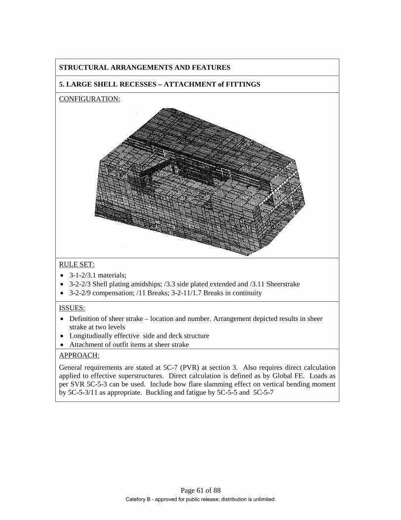
Page 61 of 88
STRUCTURAL ARRANGEMENTS AND FEATURES
5. LARGE SHELL RECESSES – ATTACHMENT of FITTINGS
CONFIGURATION:
RULE SET: • 3-1-2/3.1 materials; • 3-2-2/3 Shell plating amidships; /3.3 side plated extended and /3.11 Sheerstrake • 3-2-2/9 compensation; /11 Breaks; 3-2-11/1.7 Breaks in continuity
ISSUES: • Definition of sheer strake – location and number. Arrangement depicted results in sheer
strake at two levels • Longitudinally effective side and deck structure • Attachment of outfit items at sheer strake APPROACH:
General requirements are stated at 5C-7 (PVR) at section 3. Also requires direct calculation applied to effective superstructures. Direct calculation is defined as by Global FE. Loads as per SVR 5C-5-3 can be used. Include bow flare slamming effect on vertical bending moment by 5C-5-3/11 as appropriate. Buckling and fatigue by 5C-5-5 and 5C-5-7
Catefory B - approved for public release; distribution is unlimited.

Page 62 of 88
STRUCTURAL ARRANGEMENTS AND FEATURES
6. EXTENSIVE MAJOR DISCONTINUITIES in MID-BODY STRUCTURE
CONFIGURATION:
RULE SET:
The structural elements such as decks, shell and bulkheads are determined using the appropriate Part 3 rules.
ISSUES:
Taking account of structural interactions and response due to loads representing design requirements such as deck design loads and rule required bending shear loads.
APPROACH:
Structural validation taking account of interaction through direct calculation using 3-D FE analysis. Note when required to validate scantlings in accordance with rule and/or specification requirements direct calculation by DLA methodology may not be acceptable. DLA applies dominant load parameters with vessel loaded in accordance with loading manual. Cargo load on decks may be less than specified deck design load capacity.
Catefory B - approved for public release; distribution is unlimited.

Page 63 of 88
STRUCTURAL ARRANGEMENTS AND FEATURES
7. CARGO BEARING DECKS – SUPPORT ARRANGEMENTS
CONFIGURATION:
RULE SET: • 3-2-3/5 and 17 plating thickness • 3-2-7/3 beams, • 3-2-8/1.1, 3-2-8/3.9 3-2-8/5 Pillars, Deck Girders and Transverses • 3-2-1/19 and 3-2/A4 Buckling Strength
ISSUES: • Minimize the use of supporting stanchions to maximize stowage space in lower holds • Minimize depth of supporting grillage to maximize “tween deck stack height • Demonstrate the effectiveness of structural redundancy and multiple load paths to
supporting side structure APPROACH: • 5C-10-2/1.5 Buckling strength. Cross ref to 3-2-19. • 5C-10-2/5 Transverse strength validation by 3D FEM. • 5C -10-2/11 Deck plating, longitudinals, beams, girders, transverses and pillars 2-D grillage analysis undertaken to size main supporting members Demonstration of load paths in open vehicle deck support arrangements may best be achieved by direct calculation ( 3D FEA)
Catefory B - approved for public release; distribution is unlimited.

Page 64 of 88
STRUCTURAL ARRANGEMENTS AND FEATURES
8. LARGE OPENINGS IN EFFECTIVE INTERNAL LONGITUDINAL STRUCTURE
CONFIGURATION:
RULE SET: • 3-1-2/3.1 material grade • 3-2-1/3.7 Bending Standard; /3.9 shearing strength; /7 loading guidance; /19 buckling
strength. • 3-2-9/5 Construction of watertight bulkheads • 3-2-10 Deep tanks
ISSUES:
This longitudinal bulkhead structure often exhibits failures when subject to investigation within a global FE analysis. In complex vessels arrangement considerations take precedence over good structural design practice. • Compensation in way of openings and discontinuities • Structure around openings and corner details • Buckling, ultimate strength and fatigue assessment
APPROACH:
If a global FE analysis is performed with direct calculation loads, stresses can be used in conjunction with SVR Pt 5C Total Strength Assessment methods to investigate yielding, buckling, and fatigue. 5C-5-5 is recommended as being most applicable to complex vessels. Local models can also be used driving loads from 5C-5-3using selected relevant vessel load conditions. From tables 1A &B.
Catefory B - approved for public release; distribution is unlimited.
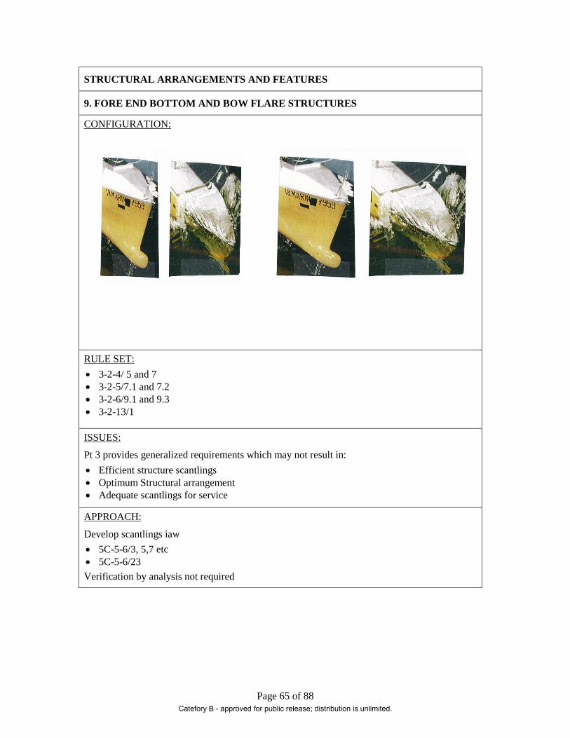
Page 65 of 88
STRUCTURAL ARRANGEMENTS AND FEATURES
9. FORE END BOTTOM AND BOW FLARE STRUCTURES
CONFIGURATION:
RULE SET: • 3-2-4/ 5 and 7 • 3-2-5/7.1 and 7.2 • 3-2-6/9.1 and 9.3 • 3-2-13/1
ISSUES:
Pt 3 provides generalized requirements which may not result in: • Efficient structure scantlings • Optimum Structural arrangement • Adequate scantlings for service
APPROACH:
Develop scantlings iaw • 5C-5-6/3, 5,7 etc • 5C-5-6/23 Verification by analysis not required
Catefory B - approved for public release; distribution is unlimited.
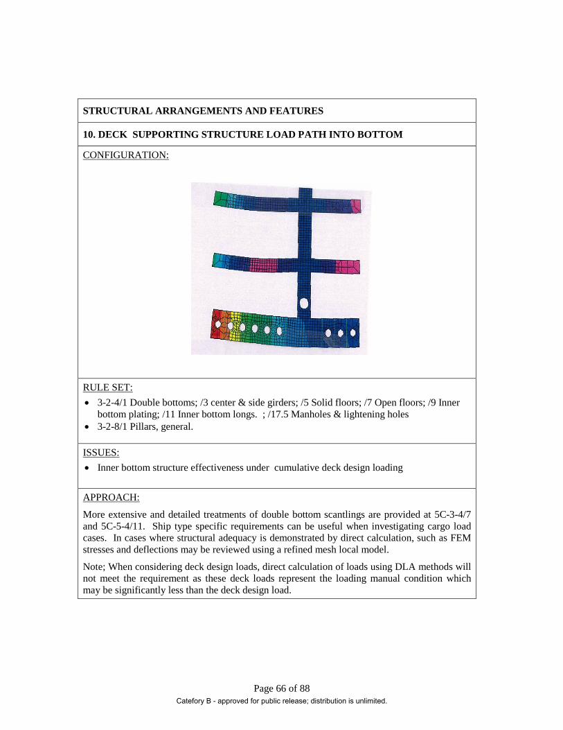
Page 66 of 88
STRUCTURAL ARRANGEMENTS AND FEATURES
10. DECK SUPPORTING STRUCTURE LOAD PATH INTO BOTTOM
CONFIGURATION:
RULE SET: • 3-2-4/1 Double bottoms; /3 center & side girders; /5 Solid floors; /7 Open floors; /9 Inner
bottom plating; /11 Inner bottom longs. ; /17.5 Manholes & lightening holes • 3-2-8/1 Pillars, general.
ISSUES: • Inner bottom structure effectiveness under cumulative deck design loading
APPROACH:
More extensive and detailed treatments of double bottom scantlings are provided at 5C-3-4/7 and 5C-5-4/11. Ship type specific requirements can be useful when investigating cargo load cases. In cases where structural adequacy is demonstrated by direct calculation, such as FEM stresses and deflections may be reviewed using a refined mesh local model.
Note; When considering deck design loads, direct calculation of loads using DLA methods will not meet the requirement as these deck loads represent the loading manual condition which may be significantly less than the deck design load.
Catefory B - approved for public release; distribution is unlimited.

Page 67 of 88
STRUCTURAL ARRANGEMENTS AND FEATURES
11. LARGE FASHION PLATE( 1.5x1.5m) in CRITICAL LOCATION
CONFIGURATION:
RULE SET: • 3-2-2/3.3.3 • 3-2-2/3.11 • 3-2-2/11 and 3-2-11/1.7
ISSUES:
The requirements provide plate thickness and general guidance on configuration. Specific requirements, particularly for breaks in critical locations is lacking
Fatigue life and buckling strength require to be assessed
Inserted shell plate requirements need to be established
APPROACH:
Fatigue and buckling assessment guidance can be found in 5C-5.A1 and A2. Note: large radiused inserts in strength deck in way of hatch openings are addressed. Orientation is horizontal rather than vertical but principles translate.
Permissible stress range guidance for sweeps, side screens etc is given in the Passenger Vessel Rules.
Note this type of structural feature may be best dealt with by direct calculation (FEA)
Catefory B - approved for public release; distribution is unlimited.

Page 68 of 88
STRUCTURAL ARRANGEMENTS AND FEATURES
12. LONG DEEP WT BKHD STIFFENERS in BENDING and COMPRESSION
CONFIGURATION:
RULE SET: • 3-2-9/5 Construction of Wt Bkhds; • 3-2-10/3 Construction of Deep Tank Bkhds
ISSUES: • Torsional stability of stiffeners in situations with excessive in-hold ‘Tween deck heights
APPROACH: • A method of assessment is provided in 5C-5-A2/5.5. • Assessment methods are also included in SafeHull
Catefory B - approved for public release; distribution is unlimited.
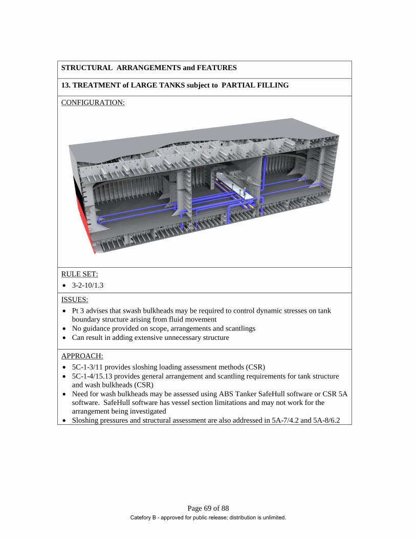
Page 69 of 88
STRUCTURAL ARRANGEMENTS and FEATURES
13. TREATMENT of LARGE TANKS subject to PARTIAL FILLING
CONFIGURATION:
RULE SET: • 3-2-10/1.3
ISSUES: • Pt 3 advises that swash bulkheads may be required to control dynamic stresses on tank
boundary structure arising from fluid movement • No guidance provided on scope, arrangements and scantlings • Can result in adding extensive unnecessary structure
APPROACH: • 5C-1-3/11 provides sloshing loading assessment methods (CSR) • 5C-1-4/15.13 provides general arrangement and scantling requirements for tank structure
and wash bulkheads (CSR) • Need for wash bulkheads may be assessed using ABS Tanker SafeHull software or CSR 5A
software. SafeHull software has vessel section limitations and may not work for the arrangement being investigated
• Sloshing pressures and structural assessment are also addressed in 5A-7/4.2 and 5A-8/6.2
Catefory B - approved for public release; distribution is unlimited.

Page 70 of 88
Appendix B - Process Templates
Catefory B - approved for public release; distribution is unlimited.

Page 71 of 88
Process Template
1 – Large Access Openings in WT Transverse Bulkheads
Determination of Loads
In the arrangement description (A-1) references made to the application of direct calculation using FE. SVR Part 5C (2)-7 (Passenger Vessel Rules) and 5C (2)-10 (Vehicle Carrier) include requirements for 3D modeling and analysis. SVR Part 5C (2)-7 is very detailed and comprehensive. For loads, reference is made to SVR Part 3-2-1/3.5 and SVR Part 5C (1)-5-3-5. Load cases are identified at 5C (2)-7-2/3.7.4 Table 1.
Criteria
For PVR, see 5C (2)-7-2/3.9 and 3.11 for strength, buckling and fatigue criteria. If a limited model in accordance with Vehicle Carrier requirements is acceptable, see strength criteria at 5C(2)-10-2/5.3.4
Method
By FE-based direct calculation in accordance with 5C(2)-7-2/3.7 and 5C (2)-10-2/5.3
Verification
Presentation of a global FE analysis with accompanying fine-mesh load models
Note: PVR requires a global 3D model. 5C (2)-10-2 requires a 3D model of the vessel section between two main transverse bulkheads.
Other options are available within Class methods, such as Dynamic Loading Analysis (DLA).
Catefory B - approved for public release; distribution is unlimited.

Page 72 of 88
Process Template
2 – Oversized Access through Effective Decks
Determination of Loads
SVR Part 5C-3 and 5C-5 take account of vessels with cargo hold openings are considered to contain requirements of interest to this arrangement feature
The deck structure will be designed taking account of effective longitudinal structure and subject to still water, wave induced and dynamic cargo loads.
Arrangement of corner details and determination of fatigue life requires careful attention.
Dynamic stress ranges can be determined by considering various combinations of vessel load cases such as; maximum hog and sag bending, maximum torsion to port and starboard. For complex load conditions see 5C(1)-5-A1/7 for detailed assessment of stress ranges
Criteria
Specification required fatigue life. Owner determined
Note that the permissible stress range method at 5C (1)- 5-A1/5 assumes a 20 year fatigue life. See 5C(1)-5-A1/5.7 for method of adjustment to greater required fatigue life
Method
Application of methods at 5C(1)-5-5/7.3 and 5C(1)-5-A1. Both permissible stress range and Stress Concentration Factor (SFC) methods are included.
Application of the SCF method may require some local FE assessment depending upon the nature of the detail.
Guidance on corner insert plates is provided at 5C (1)-5-4/17.7
In some cases Spectral Analysis may be required to properly assess fatigue life of complex arrangements. See 5C(1)-5-5/7.5 and ABS Guide “Spectral-Based Fatigue Analysis for Vessels”
Verification
Complex vessels usually require a global FE analysis, complimented by detail refined mesh sub-models of supporting structure and critical details in way of large openings. Loading may be prescriptive such as 3-2-1/3.5 or 5C (1)-5-3/5 if torsional and horizontal loadings are of concern. Assessment of cargo, tank and external pressure loads are provided at 5C(1)-5-3/5.3 & 5.5.
Direct calculation of dynamic loads can also be undertaken by ship motions analysis, such as that described in the ABS guide “‘SafeHull- Dynamic Loading Approach’ for Vessels”. Note that this method can applied without requesting a SH-DLA notation.
Stress ranges can be extracted to perform fatigue life assessments of details
Catefory B - approved for public release; distribution is unlimited.

Page 73 of 88
Process Template
3 – Major Side Ports in Side Shell
Determination of Loads
This treatment makes use of methods contained in the Passenger Vessel Rules (PVR). Application to a complex vessel would require to be confirmed with Class.
SVR Part 5C(1)-3 and 5 do not address major shell openings. Reference is made to Part 5C(2)-7 (Passenger Vessel Rules) however for wave loads, PVR refers to Pt 5C(1)-5-3/5 in the absence of direct calculation of wave-induced loads.
Fatigue assessment, buckling strength and compensation in way of major shell openings are of concern and are addressed in the PVR
Criteria
Compliance with PVR 2/3.11.2 Buckling criteria
Compliance with PVR 2/3.11.3 for Fatigue criteria 20 year fatigue life implied
See PVR 2/7.5 for requirements for compensation by inserts. Note requirement to confirm critical inserts by direct calculation.
Method
Buckling strength as per PVR 2/3.11.2 table 2 limiting stress criteria. Not the application of these criteria assume FE analysis derived stresses
Dynamic stress ranges from combined load cases, compare with allowable stress ranges in 2/3.11.3. Stress range can be adjusted to reflect greater fatigue life as per 5C-5-A1/5.7
Verification
Similar to Process Template #2
Catefory B - approved for public release; distribution is unlimited.
Page 74 of 88
Process Template
4 – Integration of Stiff and Soft Structures
Determination of Loads
Vessel mid-body global loads determined by Part 3-2-1/ 3.3 & 3.5 for bending and shear. Refer to Pt 5C -5-3/5.1 for torsion and horizontal bending if applicable .Cases should include maximum vertical hog and sag bending moments
Local operational loads as applicable to the equipment are to be included. Loads will be based on operational rating, SWL and dynamic factors. Refer to ABS “Guide for the certification of Lifting Appliances” for guidance.
Criteria
For vessel structure, strength criteria such as those at the Passenger Vessel Rules 2/3.11 or the “Guide for SafeHull-Dynamic Loading Approach for Vessels” could be applied.
The strength of support structure, criteria at 2.2/5.3 of the lifting guide can be used.
Fatigue life of connection details at sheer strake and foundation to meet specification
Method
For the structural arrangement stress ranges in way of discontinuities and openings are of interest. Due to the significant differences in stiffness between soft ship structure and the support structure FE analysis is required.
Fatigue assessment is undertaken applying methods at 5C-5-5/7 and 5C-5-A1
Verification
None required
Catefory B - approved for public release; distribution is unlimited.
Page 75 of 88
Process Template
5 – Large Shell Recesses - Fittings at Sheer Strake
Determination of Loads
Arrangement results in sheer and stringer plates in multiple locations and posses challenges with respect the attachment of mission essential equipment. Prohibitions on the attachment of fittings are stated at 3-2-2/3.11. Requirement was to demonstrate compliant fatigue life at sheer strake/fitting foundation connection. Foundation connection lay across the sheer strake.
Wave- induced stress ranges derived from longitudinal strength assessment taking account of bow flare slam induced bending moment as per 5C-3-3/11.3.3. develop stress ranges for combined vessel load conditions
May require to consider secondary and tertiary stresses if substantial transverse webs are close to the area of interest. See 5C-5-A1/7.13
Criteria
Exceed specified vessel fatigue life
Method
Assess fatigue life using Part 5C-5-5/7.3 and 5C-5-A1. Determine permissible stress range from detail at Table 2 and long term distribution function. Adjust for specified fatigue life if greater than 20 years as per 5C-5-A1/5.7. Compare with computed stress ranges for combined load cases.
Special treatment such as “grind smooth and contour weld profile” may need to be specified in fabrication instructions
Verification
Local investigation of primary structure. Independent verification of acceptability of structural proposal not required.
Catefory B - approved for public release; distribution is unlimited.

Page 76 of 88
Process Template
6 – Extensive Major Discontinuities in Mid-Body
Determination of Loads
This example is included to illustrate that in some cases there is no option but to calculate loads directly and analyze the structure using FE methods. The subject structure exhibits major openings and breaks in transverse, horizontal and vertical longitudinal planes of primary structure.
Loads calculated in accordance with ABS guide ‘SafeHull-Dynamic Loading Approach’ for Vessels. Loads to include cargo and tank contents for multiple vessel loading manual conditions and vessel headings.
Criteria
Criteria are included in the guide at section 15
Two failure modes are addressed;
Yielding
Buckling and Ultimate Strength
Note fatigue is not addressed
Method
Finite element method employing global coarse mesh and local fine mesh models subject multiple derived dominant load parameters (DLP).
Element stress results can be extracted and used to undertake fatigue life assessments using methods at 5C-5-5/7
Verification
To confirm acceptance of the structural arrangement and scantling the analysis can be submitted to Class for award of a SH-DLA notation
Catefory B - approved for public release; distribution is unlimited.

Page 77 of 88
Process Template
7 – Cargo Bearing Decks – Support Arrangements
Determination of Loads
Required to design supporting structure for heavily loaded cargo decks allowing for clear vehicle maneuvering paths. Side port access fixed. Between deck access by ramps. Cargo movement at sea (SS 5) required.
Wheeled cargo loads determined by 5C-10-2//11 for plate thickness check. Take C=1.65 (per ABS advice) for cargo movement at sea. Dynamic loads for stowed cargo using 5C-5-3/5.5 for motions and loads due to stowed cargo
It assumed that Pt 3 requirement resultant in an unsatisfactory design.
Note Stiffness requirements are given at 5C-10-2/11.7.2.
Criteria
Yielding: Where FE is performed criteria at 5C-10-2/
Buckling: to meet requirements of 3-2-1/19 and to include global effects
Stiffness: to meet requirements at 5C-10-2/11.7.2
Vibration. Extensive open loaded decks will have a low natural frequency and stiffness for compliance with specification defined structural vibration criteria may be the governing design leading to custom proportioned girders and beams
Method
For preliminary assessment of deck support structure 2-D FE analysis can be employed. His analysis will determine scantlings of supporting structure. Beams and Girders should be represented by plate elements and end fixed at vessel side. Girders and transverses may be proportion constrained due to clear deck height requirements.
In multi-deck arrangements a cargo hold 3-D model should be employed.
Verification
For Vehicle Carrier Notation a 3-D FEM will be required
Although not a Class issue a forced vibration analysis may be required to support scantling design
Catefory B - approved for public release; distribution is unlimited.

Page 78 of 88
Process Template
8 – Large Openings in Effective Internal Longitudinal Structure
Determination of Loads
In complex vessels, due to arrangement considerations structure may be required in locations which attract high stresses and stress ranges. These planes of structure may be discontinuous, have large access openings and are non-watertight. Structural members exhibit yielding, buckling and fatigue failures.
Predominant load cases of interest are vertical bending; taking account of bow flare induced slamming effect upon bending moment and shear force.
Methods of determining and combining load global, cargo and tank loads are addressed at 5C-5-3
Criteria
Assessed for yielding, and buckling as per 5C-5-5/3 and /5 with 5C-5-A2
Fatigue assessment using permissible stress range approach 5C-5-5/7.3 and 5C-5-A1
Method
Treatment of internal NWT longitudinal bulkheads is not addressed other than recognizing them as “effective” if meeting the requirements for effective structure and including them in Longitudinal Strength Assessment (3-2-1)
WT longitudinal bulkheads are addressed at 5C-5-4/5.4 and 5C-5-4/21.5. Note that 5C-5-4/5.1 imposes a transverse location requirement. Confirm acceptability with Class
Method considered conservative for establishing scantlings prior to direct calculation
Verification
For this structural arrangement a 3-D FEM is recommended. Extent of model to be agreed with Class. Global bending and shearing forces are to be applied in addition to local loads including wave dynamic effects. Investigation of hog and sag vertical bending cases for light and load conditions required. Resulting element stresses can be used with 5C-5-5 criteria
Catefory B - approved for public release; distribution is unlimited.

Page 79 of 88
Process Template
9 – Fore End Bottom and Bow Flare Structures
Determination of Loads • 5C-5-3 / 5.3.4a Bow Pressures • 5C-5-3 / 11.1 Bottom Slamming Pressure • 5C-5-2 / 11.3
Criteria
Bottom Slamming
Plate • f as defined in 5-5-4 / 11.3 and 5-5-6 / 23.1.1 Longitudinals • fb as defined in 5-5-4 / 11.3 and 5-5-6 / 23.1.1 Bow Flare
Plate • f as defined in 5-5-4 / 11.3 and 5-5-6 / 23.1.1 Side Longs • fb as defined in 5-5-4 / 11.3.1 and 5-5-6 / 23.3.2 Side Transverses and Stringers • fb as defined in 5-5-4 / 11.3.1 and 5-5-6 / 23.3.3
Method
Plate
( )2/1
11
=
fP
kSct s
Longitudinals
bfMSM =
Verification
Not Required
Catefory B - approved for public release; distribution is unlimited.

Page 80 of 88
Process Template
10 – Deck Supporting Structure Load Path into Bottom
Determination of Loads
Local loads accounting for cargo are obtained from vessel requirements. Use design loads where required. Cargo loads may be derived 5C-5-3/5.5.2 in conjunction wih5C-5-3/table 1C using an appropriate cargo load characteristic.
Criteria
Based on the application of the equations in 5C-5-4/11which include permissible stresses, yielding of members will be satisfied however attention needs to be paid to stresses at the corners of access holes and cutouts in floors.
Buckling can be addressed by using the methods at 5C-5-A2
Experience has indicated that for the complex vessels with double bottom arrangements fatigue is not an issue.
As with SVR Pt 3, the selected Pt 5 requirements are silent on the treatment of stanchions and transmission of cumulative loads into the bottom structure
Method
Scantlings for each structural component determined as per 5C-5-4/11. Detailed equations are provided for bottom shell, inner bottom plate, shell and inner bottom longs, bilge plate struts in floors, center line and side girders, tank boundary girders, bottom floors etc
Applying these equations to scantling sizing will result in a design better suited complex vessel structural requirements. Note these equations have been developed for container carrier cargo hold structure.
Verification
The distribution of stanchion loads into the bottom and the resulting structural response has been a subject of interest to Class. F E analysis has proven effective in responding to Class comments. A model spanning one cargo hold and including bounding bulkheads has been found to provide satisfactory results.
Models have been developed as per ABS Guide “SafeHull Finite Element Analysis for Hull Structures”. As noted above global, cargo and tank loading as per 5C-5-3 have been applied and response assessed against DLA criteria as per “SafeHull-Dynamic Loading Approach for Vessels”
Catefory B - approved for public release; distribution is unlimited.

Page 81 of 88
Process Template
11 – Fashion Plate
Determination of Loads
In A-13 reference is made to assessing fatigue acceptability on the basis of dynamic stress range. This simple method inherently assesses compliance with a 20 year fatigue life consistent with Part 3 expectations.
The dynamic stress range can be determined from a longitudinal strength assessment developed in accordance with SVR 3-2-1
Criteria
Passenger Vessel Rules Section 2/3.11.3
Method
Determine wave bending stresses for maximum hog and sag conditions. Determine stress range
Verification
When subject to more rigorous methods of assessment , such as spectral fatigue analysis, fashion plates often show crack initiation sites with low fatigue lives at the ends and mid-span
For practical purposes methods such as those at 5C-5-A1/5 and 7 are recommended.
Catefory B - approved for public release; distribution is unlimited.

Page 82 of 88
Process Template
12 – Long Deep WT Bulkhead Stiffeners in Bending and Compression
Determination of Loads
To check torsional buckling of long span deep stiffeners on bulkheads.
This is a case in which the method was recommended by Class although the orientation is intended for decks rather than transverse bulkhead stiffeners. The formulation provided a critical stress that is compared to element stresses from an FE analysis or derived from analysis using loading based on the loading criteria and nominal design loads at 5C-5-3 and 5C-5-4.
These calculations are automated in the SafeHull (SH) system for Container Carriers and depending upon the vessel structural arrangement SH may be applicable.
Criteria
Computed stress < critical stress, fct (critical torsional/flexural ultimate stress)
Method
Requirements are at 5C-5-5/5.5
Calculate fct for members using equation at 5C-5-A2/5.5.1
Verification
No verification required
Catefory B - approved for public release; distribution is unlimited.

Page 83 of 88
Process Template
13 – Treatment of Large Tanks Subject to Partial Filling
Determination of Loads
Both the ABS SVR Part 5A and 5C address sloshing. Reference is made to the Tanker Common Structural Rules (Part 5A) in the process template. • 5A-7 / 4.2.2 Sloshing Pressure due to Longitudinal Liquid Motion • 5A-7 / 4.2.3 sloshing Pressure due to Transverse Liquid Motion • 5A-7 / 4.2.4 Minimum Sloshing Pressure
Criteria
Demonstrate compliance with 5A-8/6.2.3, 4 and 5 and permissible stress coefficient in accordance with Tables 8.6 1, 2, and 3.
Method • 5A-8 / 6.2.3 Sloshing Assessment of Tank Boundary Plating • 5A-8 / 6.2.4 Sloshing Assessment of Tank Boundary Stiffeners • 5A-8 / 6.2.5 Sloshing Assessment of Primary Support Members
Verification
Not required
Catefory B - approved for public release; distribution is unlimited.

Page 84 of 88
Appendix C - Steel Vessel Rules Part 3 Primary Structure Requirements
Catefory B - approved for public release; distribution is unlimited.

Page 85 of 88
Chapter Sections Subjects of Interest
1. General 1.1 Definitions Length Depth Decks
1.2 General Requirements
Design Considerations Material Grade Selection Scantlings Proportions Deep Supporting Members Frames, Beams, and Stiffeners Structural Design Details Termination of Structural Members
2. Hull Structures & Arrangements
2.1 Longitudinal Strength
Appendix 1
Appendix 4
Still-Water Bending Moment & Shear Force Wave Loads Bending Strength Standard Shearing Strength Higher-Strength Materials Allowable Stresses Section Modulus Strength Decks Continuous Longitudinal Hatch Coamings Effective Lower Decks Longitudinal Structure Inboard of Lines of Openings Buckling Strength (Longitudinal) Shear Stress for Vessels with Longitudinal Bulkheads Buckling Strength of Longitudinal Strength Members
2.2 Shell Plating Thickness Superstructures Side Shell Plating Sheer Strake Bottom Shell Plating Keel Minimum Thickness Shell Plating at Ends, Minimum Thickness Immersed Bow Plating Bottom Forward Forecastle Side Plating Thruster Tunnels Special Heavy Plates Docking Compensation Breaks Higher-Strength Materials
2.3 Decks Section Modulus Deck Transitions Thickness Effective Lower Decks Reinforcement at Openings Platform Decks
Catefory B - approved for public release; distribution is unlimited.

Page 86 of 88
Chapter Sections Subjects of Interest Watertight Flats Retractable Tween Decks Wheel Loading Higher-Strength Materials –Thickness, Buckling Wheel Loading
2.4 Bottom Structures Double Bottoms Center & Side Girders Pipe Tunnel Thickness Docking Brackets Side Girders Solid Floors - Thickness, Tank End Floors, Floor Stiffeners Open Floors Inner Bottom Plating Engine Bed Plates Thrust Blocks Bottom and Inner Bottom Longitudinals Fore end Extent of Strengthening Longitudinal Framing Transverse Framing Higher-Strength Materials Structural Arrangements and Details Sea Chests Drainage Manholes and Lightening Holes
2.5 Frames Considerations Holes in frames End Connections Hold Frames – Transverse, Section Modulus, Raised quarter decks Fore End Frames Panting Frames Side Stringers Frames with Web Frames & Side Stringers Panting Webs and Stringers Hold Frames Brackets Longitudinal Frames ‘Tween decks transverse frames Longitudinal Frames Fore Peak Frames Scantlings Aft Peak Frames
2.6 Web Frames Spacing Section Modulus Frames Forward Proportions Stiffeners Tripping Brackets Tween Deck Webs Side Stringers Stiffeners, Tripping Brackets Details, Brackets Girders
Catefory B - approved for public release; distribution is unlimited.

Page 87 of 88
Chapter Sections Subjects of Interest Webs and Stringers End Connections Peak Stringers Thickness Breadth
2.7 Beams Arrangement Design Load Section Modulus Heavy Beams End Connections Deck Fittings Design Loads Supporting Structures Scantlings Container Loading Higher-Strength Materials
2.8 Pillars, Deck Girders, and Transverses
Arrangement Permissible Load Calculated Load Special Pillars Pillars Under Deep Tank Tops Bulkhead Stiffening Attachments Deck Girders and Transverses Deck Girders Clear of Tanks Deck Transverses Section Modulus Proportions of Tripping Brackets Deck Girders and Transverses in Tanks Hatch Side Girders Hatch End Beams Weather Deck Hatch End Beams Depth and Thickness Brackets, Higher-Strength Materials
2.9 Watertight Bulkheads and Doors
Arrangement Construction of Bulkheads Plating Thickness Stiffener Section Modulus Attachments Girders and Webs Proportions Tripping Brackets Corrugated Bulkheads Thickness Section Modulus, End Connections Watertight Doors Construction
2.10 Deep Tanks Arrangement Construction Bulkheads Plating Thickness Stiffener Section Modulus Tank Top Plating Girders and Webs Section Modulus Proportions, Tripping Brackets
Catefory B - approved for public release; distribution is unlimited.

Page 88 of 88
Chapter Sections Subjects of Interest Corrugated Bulkheads Higher-Strength Materials
2.11 Superstructures, Deckhouses, and Helicopter Decks
Scantlings Side Plating Decks Frames Breaks Exposed Bulkheads Plating, Section Modulus End Attachments Raised Quarter Deck Bulkheads Forecastle Structures
2.12 Machinery Space & Tunnel
Arrangement Foundations Tunnels Plating Stiffeners Tunnels Through Deep Tanks Thickness
2.13 Protection of Deck Openings
Design Pressures Height of coamings Plating Continuous longitudinal coamings
2.14 Protection of Shell Openings
General Construction Requirements Support of closures Loads and criteria for closures
2.15 Weld Design Fillet Welds Tee Connections Intermittent Welding Welding of Longs to Plate Thin Plate Tee-Type End Connection Reduced Weld Size Lapped Joints
Catefory B - approved for public release; distribution is unlimited.