shambhunath institute of engineering and technology
TRANSCRIPT
SHAMBHUNATH INSTITUTE OF ENGINEERING AND TECHNOLOGY
FLUID MACHINERY (RME-601)
B.TECH. SIXTH SEMESTER
FIRST SESSIONAL EXAMINATION, EVEN SEMESTER, (2019-2020)
BRANCH: MECHANICAL ENGINEERING
Time –1hr. 30 min Maximum Marks – 30
SECTION – A
1. Attempt all questions in brief: (5*1 = 5) Q.N. QUESTION Marks CO BL
a.
State the impulse momentum principle.
Solution: The impulse-momentum theorem states that the change in momentum of an
object equals the impulse applied to it. The impulse-momentum theorem is logically
equivalent to Newton's second law of motion (the force law).
1 1 1
b. Define degree of reaction.
Solution: Degree of reaction or reaction ratio (R) is defined as the ratio of the pressure
energy change in the rotor to the total energy change.. 1 1 1
c.
Differentiate between impulse turbine and a reaction turbine?
Solution: The basic and main difference between impulse and reaction turbine is that
there is pressure change in the fluid as it passes through runner of reaction turbine while
in impulse turbine there is no pressure change in the runner. ... So it uses kinetic energy as
well as pressure energy to rotate the turbine.
1 1 1
d.
What is the function of the nozzle in an impulse turbine?
Solution: Nozzle is used to increase the kinetic energy of water. It increases the velocity
and decreases the pressure. 1 2 1
e. Write the specifications of francis turbine.
Solution: It is a medium head, medium discharge, mixed flow, medium specific speed. It
is a type of radially inward flow reaction turbine 1 2 1
SECTION - B
2. Attempt any two parts of the following: (2*5 = 10)
Q.N. QUESTION Marks CO BL
a.
Explain the Governing of a Pelton Turbine. Use neat sketch.
Solution:
Governing of Pelton Turbine (Impulse Turbine)
Governing of Pelton turbine is done by means of oil pressure governor, which consists of the following parts :
1. Oil sump.
2. Gear pump also called oil pump, which is driven by the power obtained from turbine shaft
3. The Servomotor also called the relay cylinder.
4. The control valve or the distribution valve or relay valve.
5. The centrifugal governor or pendulum which is driven by belt or gear from the turbine shaft.
6. Pipes connecting the oil sump with the control valve and control valve with servomotor and
7. The spear rod or needle. Figure shows the position of the piston in the relay cylinder, position of control or relay raise and fly-balls of the centrifugal governor, when the turbine is running at the normal speed.
5 1 2
Roll No.

When the load on the generator decreases, the speed of the generator increases. This increases the speed of the turbine beyond the normal speed. The centrifugal governor, which is connected to the turbine main shaft, will be rotating at an increased speed . Due to increase in the speed of the centrifugal governor, the fly-balls move upward due to the increased centrifugal force on them. Due to the upward movement of the fly-balls, the sleeve will also move upward. A horizontal lever, supported over a fulcrum, connects the sleeve and the piston rod of the control valve. As the sleeve moves up, the lever turns about the fulcrum and the piston rod of the control valve moves downward. This closes the V1 and opens the valve V2 as shown in Figure.
The oil, pumped from the oil pump to the control valve or relay valve, under pressure will flow through the valve V2 to the servomotor (or relay cylinder) and will exert force on the face A of the piston of the relay cylinder. The piston along with piston rod and spear will move towards right. This will decrease the area of flow of water at the outlet of the nozzle. This decrease of area of flow will reduce the rate of flow of water to the turbine which consequently reduces the speed of the turbine-When the speed of the turbine becomes normal, the fly-balls, sleeve, lever and piston rod of control valve come to its normal position as shown in Figure.
When the load on the generator increases, the speed of the generator and hence of the turbine decreases. The speed of the centrifugal governor also decreases and hence centrifugal force acting on the fly-balls also reduces. This brings the fly-balls in the downward direction. Due to this, the sleeve moves downward and the lever turns about the fulcrum, moving the piston rod of the control valve in the upward dir ection. This closes the valve V2 and opens the valve V1. The oil under pressure from the control valve, will move through valve V1 to the servomotor and will exert a force on the face B of the piston. This will move the piston along with the piston rod and spear towards left, increasing the area of flow of water at the outlet of the nozzle. This will increase the rate of flow of water to the turbine and consequently, the speed of the turbine will also increase, till the speed of the turbine becomes normal.
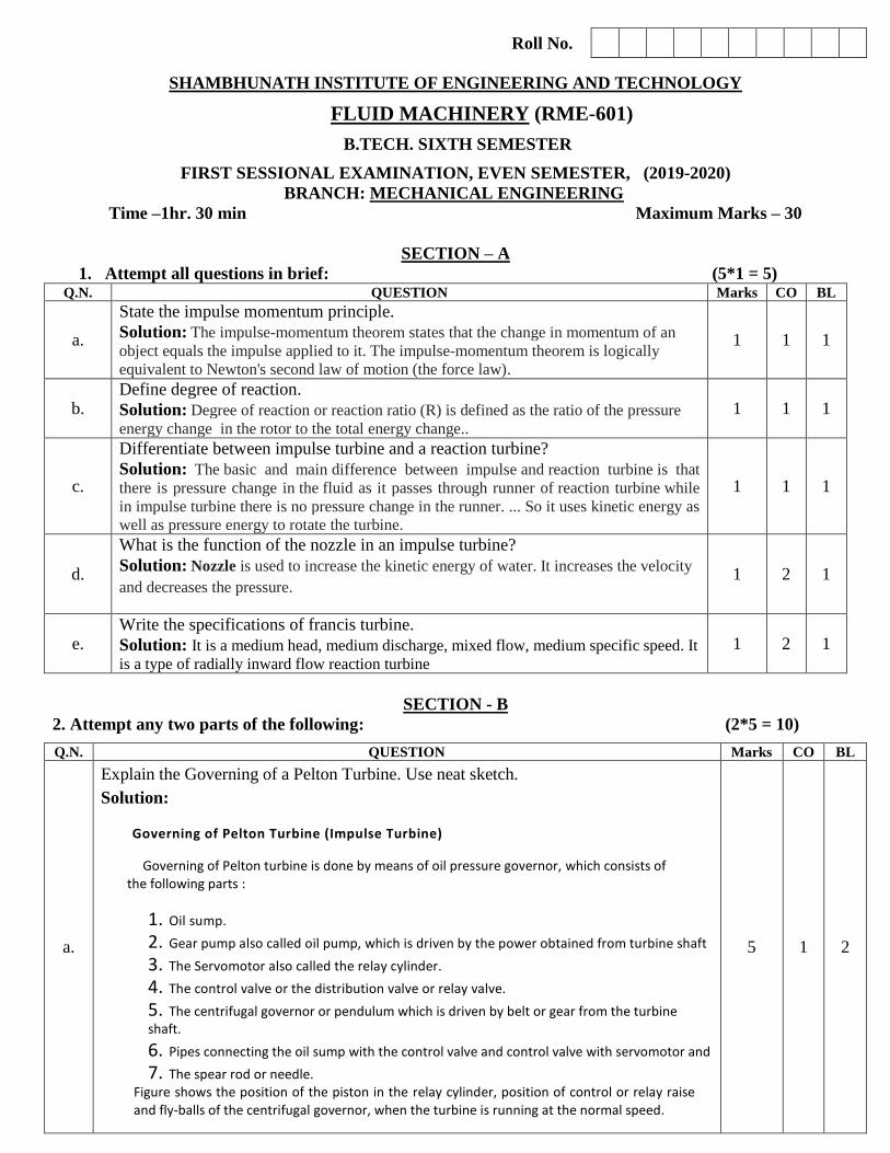
b. A jet of water of diameter 50 mm having a velocity of 20 m/s strikes at inlet of a
curved vane which is moving with a velocity of 10 m/s in the direction of the jet. The
jet leaves the vane at an angle of 60o to the direction of motion of vane at outlet.
Determine the force exerted by the jet on the vane in the direction of motion and
work done per second by the jet.
Solution:
5 1 1
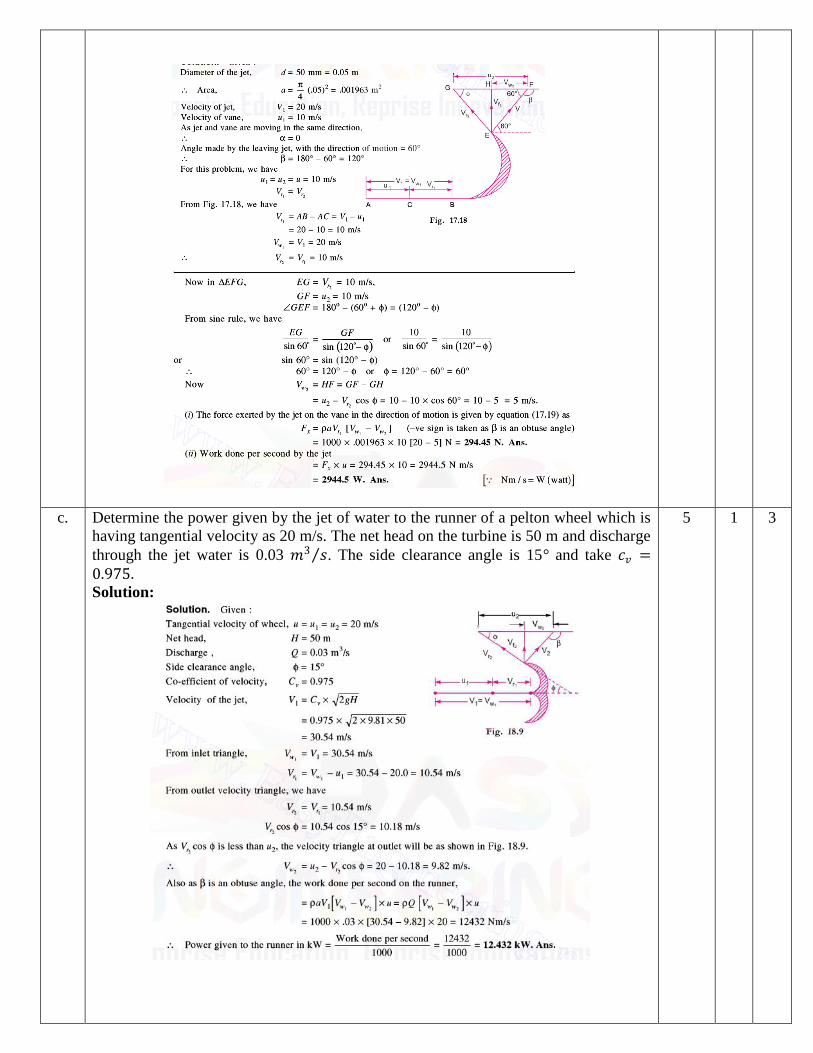
c. Determine the power given by the jet of water to the runner of a pelton wheel which is
having tangential velocity as 20 m/s. The net head on the turbine is 50 m and discharge
through the jet water is 0.03 𝑚3 𝑠 . The side clearance angle is 15° and take 𝑐𝑣 =0.975. Solution:
5 1 3
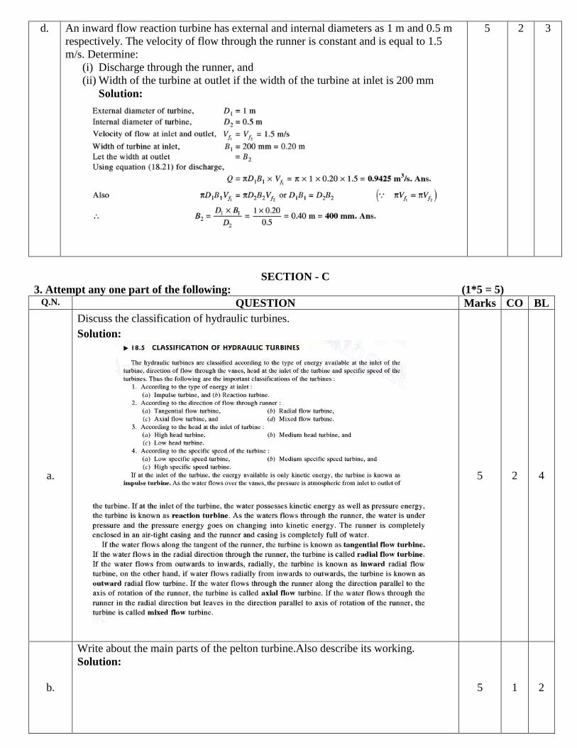
d. An inward flow reaction turbine has external and internal diameters as 1 m and 0.5 m
respectively. The velocity of flow through the runner is constant and is equal to 1.5
m/s. Determine:
(i) Discharge through the runner, and
(ii) Width of the turbine at outlet if the width of the turbine at inlet is 200 mm
Solution:
5 2 3
SECTION - C
3. Attempt any one part of the following: (1*5 = 5) Q.N. QUESTION Marks CO BL
a.
Discuss the classification of hydraulic turbines.
Solution:
5 2 4
b.
Write about the main parts of the pelton turbine.Also describe its working.
Solution:
5 1 2
4. Attempt any one part of the following: (1*5 = 5) Q.N. QUESTION Marks CO BL
a.
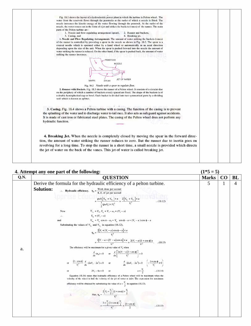
Derive the formula for the hydraulic efficiency of a pelton turbine.
Solution:
5 1 4

b. A Francis turbine with an overall efficiency of 76% is required to produce 150 kW
power. It is working under a head of 8 m. The peripheral velocity = 0.25 2gh and
the radial velocity of flow at inlet is 0.95 2gh. The wheel runs at 150 r.p.m. and the
hydraulic losses in the turbine are 20 % of the available energy. Assuming radial
discharge, determine :
(i) The guide blade angle, (ii) The wheel vane angle at inlet,
(iii) Diameter of the wheel at inlet, and (iv) Width of the wheel at inlet.
Solution:
5 2 6

5. Attempt any one part of the following: (1*5 = 5) Q.N. QUESTION Marks CO BL
a. An Inward flow reaction turbine works at 450 rpm under a head of 120 m. Its diameter at inlet is
120 cm and the flow area is 0.4 m2.The angles made by absolute and relative velocities at inlet are
20°and 60° respectively with the tangential velocity. Determine: (i)Volume flow rate, (ii) The
power developed and (iii) Hydraulic efficiency .Assume Whirl at outlet to be zero.
Solution:
5 2 5
b. Establish the relation 𝑅 = 1 − 𝑣1
2−𝑣22
2𝑔𝐻𝑒 .Where R is the degree of reaction.
Solution:
5 2 4
