shake table testing of a 10-story mass timber building
TRANSCRIPT

1
Shake Table Testing of a 10-story Mass Timber Building with Nonstructural Components
Keri L. Ryan, Shiling Pei, Tara Hutchinson
1Associate Professor, Civil and Environmental Engineering, University of Nevada Reno, 1664 N. Virginia
St., Reno, NV 89557; [email protected] 2Associate Professor, Civil and Environmental Engineering, Colorado School of Mines, 1500 Illinois St.,
Golden, CO 80401; [email protected] 3Professor, Structural Engineering, Jacobs School of Engineering, UC San Diego, La Jolla, CA 92093;
ABSTRACT
To advance the wood products market, new design solutions for tall wood buildings using mass timber products are being developed. In particular, post-tensioned cross-laminated timber (CLT) rocking walls
have been proposed as a seismic resilient lateral system. To advance the seismically resilient CLT rocking
walls for tall buildings, a comprehensive shake table test of a 10-story building with CLT rocking walls is
planned for 2021 on the NHERI@UC San Diego outdoor shaking table. An essential aspect of building resilience is assurance that nonstructural components (NCSs) sustain minimal damage or are easily
repairable; however, a number of aspects specific to rocking wall systems and their impact on NCSs are
not well understood. This test is the culmination of the NHERI TallWood Project that aims to develop seismic design methodology for resilient timber buildings. An essential aspect of building resilience is
assurance that NCSs sustain minimal damage or are easily repairable; however, a number of aspects specific
to rocking wall systems and their impact on NCSs are not well understood.
In this paper, preliminary plans for a seismic shake table test of a 10-story mass timber building are
described, and a vision for incorporating NCSs into the test program is presented. Due to the lack of shake
table test data of exterior skin systems with glazing, a key objective is to characterize the response of a
variety of curtain wall and light-framed window wall type systems, and to validate industry standard racking
tests as predictors of seismic performance. In addition, detailing improvements for stairs, interior partition
walls, and suspended ceilings are proposed. The project team is actively seeking industry and academic
collaborators for testing of various NCSs to capitalize on this opportunity.
1.0 INTRODUCTION
Typical light frame wood stud walls sheathed with wood structural panels are limited to low or mid-rise
construction. To expand the wood products market, industry aims to develop and promote the application
of new tall wood buildings built from mass timber products. The greatest challenge to taller wood construction is the development of a reliable lateral load system that can produce predictable response and
minimal damage when subjected to strong seismic shaking. Recent research aims to enhance the seismic
performance of these buildings through use of a cross-laminated timber (CLT) rocking wall lateral system that accommodates the seismic deformation demands by rocking about the base. These promising CLT
systems use post-tensioning rods anchored from the top of the wall to the foundation for restoring force and
recentering capability, with external energy dissipation devices to reduce drift demands.
To advance seismically resilient CLT rocking wall systems for tall buildings, a landmark shake table test
of a 10-story building with CLT rocking walls is planned for 2021 on the NHERI@UC San Diego outdoor
2
shaking table. This test is the culmination of the NHERI TallWood Project that aims to develop a seismic
design methodology for resilient timber buildings. An essential aspect of building resilience is assurance
that nonstructural components (NCSs) sustain minimal damage or are easily repairable; however, a number
of aspects specific to rocking wall systems and their impact on NCSs are not well understood. The
NHERI@UC San Diego shake table facility is in the process of being upgraded to allow 6-degree-of-
freedom (DOF) input motions. The planned CLT tall building test program in 2021 will be the first tall
building tested on the newly upgraded facility.
Uniquely, the 10-story building specimen will incorporate a variety of NCSs, such as facades and egress
(stairs). Architects and engineers envision mass timber buildings to be clad with lightweight façades, such
as curtain wall, storefront, and light-framed window wall type systems. Glass facades have not been
evaluated under rigorous shake table testing. The inclusion of several different systems through industry
stakeholder participation is envisioned. The height of the test building allows testing of stairs with a variety
of connection details, including expansion joints that better accommodate floor-to-floor interstory
movement. Additional NCSs will be strategically located in the building so that they are subjected to
variable demands; for example, NCSs at lower levels are subjected to larger drifts while NCSs at upper
levels are subjected to larger accelerations. The objectives of this paper are to discuss the basic
configuration and preliminary gravity and lateral design of the 10-story building specimen, explain the test
objectives and test plan, and present a vision for the inclusion of NCSs. The project presents an opportunity
for collaboration with other academic and industry partners.
2.0 DESCRIPTION OF 10-STORY TEST BUILDING
2.1 Configuration
The preliminary design of the 10-story building was completed by the second author in collaboration with
structural engineers and architects from KPFF, Holmes Structures, and Lever Architecture. Several
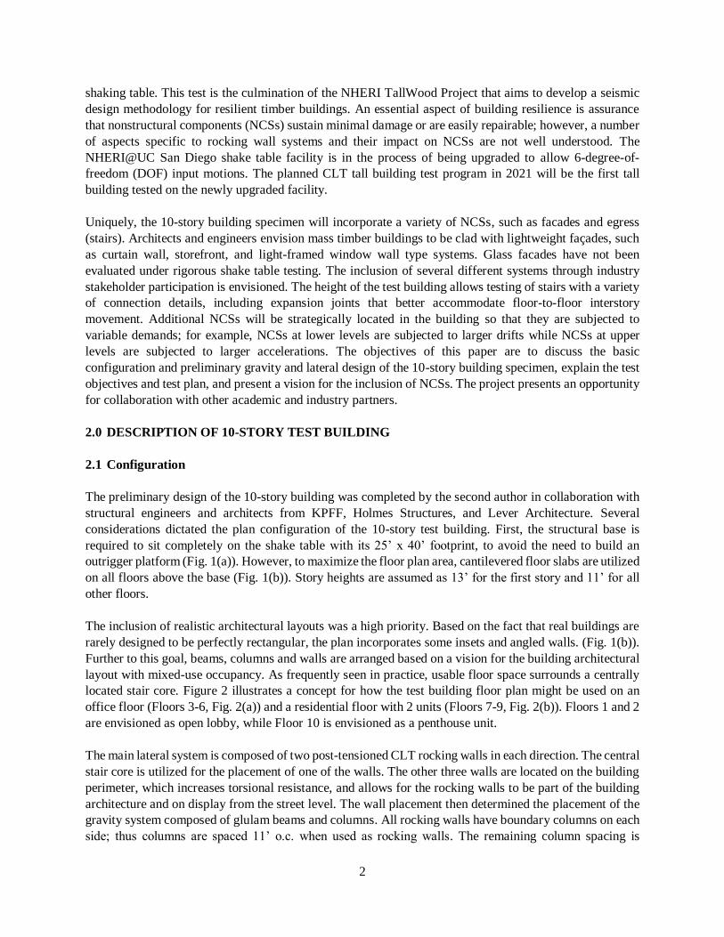
considerations dictated the plan configuration of the 10-story test building. First, the structural base is
required to sit completely on the shake table with its 25’ x 40’ footprint, to avoid the need to build an
outrigger platform (Fig. 1(a)). However, to maximize the floor plan area, cantilevered floor slabs are utilized
on all floors above the base (Fig. 1(b)). Story heights are assumed as 13’ for the first story and 11’ for all
other floors.
The inclusion of realistic architectural layouts was a high priority. Based on the fact that real buildings are
rarely designed to be perfectly rectangular, the plan incorporates some insets and angled walls. (Fig. 1(b)).
Further to this goal, beams, columns and walls are arranged based on a vision for the building architectural
layout with mixed-use occupancy. As frequently seen in practice, usable floor space surrounds a centrally
located stair core. Figure 2 illustrates a concept for how the test building floor plan might be used on an
office floor (Floors 3-6, Fig. 2(a)) and a residential floor with 2 units (Floors 7-9, Fig. 2(b)). Floors 1 and 2
are envisioned as open lobby, while Floor 10 is envisioned as a penthouse unit.
The main lateral system is composed of two post-tensioned CLT rocking walls in each direction. The central
stair core is utilized for the placement of one of the walls. The other three walls are located on the building
perimeter, which increases torsional resistance, and allows for the rocking walls to be part of the building
architecture and on display from the street level. The wall placement then determined the placement of the
gravity system composed of glulam beams and columns. All rocking walls have boundary columns on each
side; thus columns are spaced 11’ o.c. when used as rocking walls. The remaining column spacing is

3
dictated by the geometric constraints (Fig. 1(a)). Glulam beams are utilized in the E-W direction only,
between all columns except offset as needed at rocking wall locations (Fig. 1(b)). A 3D rendering of the
structural system is shown in Fig. 3.
2.2 Gravity Design
The gravity system was designed according to the National Design Specification for Wood Construction
(AWC, 2015), using Allowable Stress Design. The gravity members are designed for 60 psf dead load for
all floors and 50 psf live load for office occupancy or 40 psf live load for residential occupancy, plus 15 psf
partition load, for all floors excluding the roof. The seismic mass to be applied during testing is 70 psf,
(a) (b)
Figure 1. Structural plan layout of 10-story test building: (a) base level on shake table (table outline in blue), (b)
typical floor plan (floor panel edge boundary in gray).
Figure 2. Representative architectural floor plan layout for (a) lower story office occupancy, and (b) upper story
residential occupancy. building structural system
(a) (b)

4
which will be achieved by adding steel plates. In addition, all columns and beams are designed with
sacrificial layers ensuring 2 hour fire rating (@ 3.6 inch/hr char rate on all exposed surfaces).
Beams and columns are assumed to be glulam Western Species 24F-
1.8E stress class or equivalent. The floor diaphragms are 3 Ply CLT
(4.125”) PRG320 – compliant panels. The 3-ply floor panels satisfy the
requirements for gravity design, but the team is anticipating upgrading
to 5-ply to accommodate exterior skins hung from the cantilevered
edges. The CLT floor panels will be fabricated in 6 pieces per floor with
strategic geometry that will allow them to be moved into place around
the columns.
Table 1. Structural system member dimensions
Member
Cross-Section
Dimension or
Thickness (in)
Columns (Floor 1-2) 12.25 x 15
Columns (Floor 3-6) 12.25 x 13.5
Columns (Floor 7-10) 12.25 x 12
Rocking wall boundary
columns (All Floors)
12.25 x 18
Beam (All) 12.25 x 13.5
CLT floor panel (3-ply) ~4-1/8
Rocking wall Panel (9-ply) ~12-3/8
2.3 Lateral Design
As mentioned previously, the lateral resistance is dominated by two post-tensioned CLT rocking walls in
each direction. The walls are designed to rock up off the base, while each wall is post-tensioned through
the center to provide a restoring force. The post-tensioning rods are designed to resist the moment that
develops at the base of the wall. In addition, each wall is encapsulated by boundary columns. The wall and
columns are connected by U-shaped flexural plates (UFPs) at every other story that dissipate energy when
subjected to relative motion between the wall and the columns. The UFPs are designed to transmit the
vertical shear that develops from the relative vertical displacement between the rocking wall and the
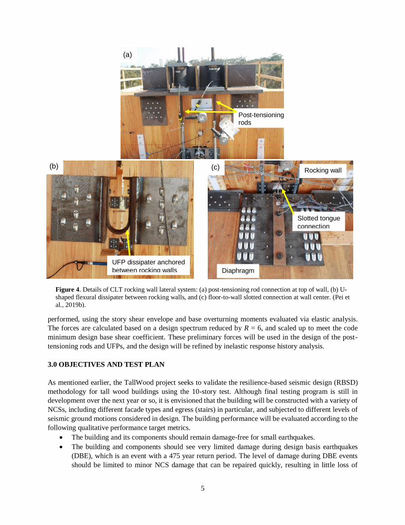
bounding columns. Sample connection details for post-tensioning rods and UFP dissipaters are shown in
Figs. 4(a) and 4(b), respectively. These details were utilized in a prior shake table test of a 2-story building
with CLT rocking walls and performed adequately (Pei et al., 2019a). A floor-to-wall tongue connection at
the center of the wall is utilized (Fig. 4(c)). Walls are attached to the floor diaphragms by a vertically slotted
shear key that allows movement of the wall relative to the diaphragm. This detail, used in the 2-story
building test (Pei et al., 2019a) was effective to prevent diaphragm distortion during wall uplift.
The preliminary CLT panel design has been validated by response spectrum analysis using SAP 2000, and
based on ASCE 7-16 specifications. A design spectrum and maximum considered earthquake risk-targeted
(MCER) spectrum assuming a location in downtown Seattle are utilized. The seismic weight is estimated
assuming an area dead load of 70 psf on each floor that includes the floor diaphragm, and self-weight of
the structural framing. For this analysis, the CLT walls are modeled with thin shell elements and CLT E1M5
structural laminated wall panel material. The preliminary design for drift is based on an equivalent linear
elastic analysis of a fixed base shear wall subjected to unreduced forces. A strength design check is also
Figure 3. 3D rendering of 10-
story building structural system
5
performed, using the story shear envelope and base overturning moments evaluated via elastic analysis.
The forces are calculated based on a design spectrum reduced by R = 6, and scaled up to meet the code
minimum design base shear coefficient. These preliminary forces will be used in the design of the post-
tensioning rods and UFPs, and the design will be refined by inelastic response history analysis.
3.0 OBJECTIVES AND TEST PLAN
As mentioned earlier, the TallWood project seeks to validate the resilience-based seismic design (RBSD)
methodology for tall wood buildings using the 10-story test. Although final testing program is still in
development over the next year or so, it is envisioned that the building will be constructed with a variety of
NCSs, including different facade types and egress (stairs) in particular, and subjected to different levels of
seismic ground motions considered in design. The building performance will be evaluated according to the
following qualitative performance target metrics.
The building and its components should remain damage-free for small earthquakes.
The building and components should see very limited damage during design basis earthquakes
(DBE), which is an event with a 475 year return period. The level of damage during DBE events
should be limited to minor NCS damage that can be repaired quickly, resulting in little loss of
Figure 4. Details of CLT rocking wall lateral system: (a) post-tensioning rod connection at top of wall, (b) U-
shaped flexural dissipater between rocking walls, and (c) floor-to-wall slotted connection at wall center. (Pei et
al., 2019b).
(a)
(b) (c)
Post-tensioning rods
UFP dissipater anchored
between rocking walls
Slotted tongue
connection
Rocking wall
Diaphragm
6
functionality after earthquakes. In other words, the minor repair work can be completed without
significant interruption to occupants.
At the MCE level, which is associated with a 2475 year return period event, the building is expected
to experience some repairable structural damage (such as yielding of post tensioning bars) and
moderate NCS damage, which may correspond to a relatively short downtime for the entire building
to be inspected and repaired.
The research team will compare the actual test performance to the intended resilience design targets used
in the design of the building. The central idea of the validation is to achieve controllable downtime at
different intensity levels through RBSD. Furthermore, the test serves as a great opportunity to expand the
database for development of fragilities for NCSs, and to evaluate the drift compatibility and resilience of
NCSs that use both traditional and improved details.
The program will also include a number of small intensity tests for building dynamic characterization,
followed by a few DBE level tests to demonstrate resilience of the structural system and possibly very
limited NCS damage. The research team will collect data along the way to help develop damage and repair
fragilities for NCSs installed in the building. Finally the test will be concluded with 1~3 MCE level tests to
examine the building performance in rare earthquakes. It is expected that the test program will take
advantage of the 3D excitation capacity of the UCSD shake table to be added in 2020.
4.0 VISION FOR NCSs
4.1 Facades
Architects and engineers envision mass timber buildings to be
clad with lightweight façades with a high degree of transparency.
The architectural vision is to display the rocking walls and much
of the structural wood so that the building is perceived as a timber
high rise from the street level. Examples of suitable facades are
curtain wall and storefront, as well as light-gage steel or timber
framed with metal panel skin, and a high percentage of window
opening (e.g. window wall system).
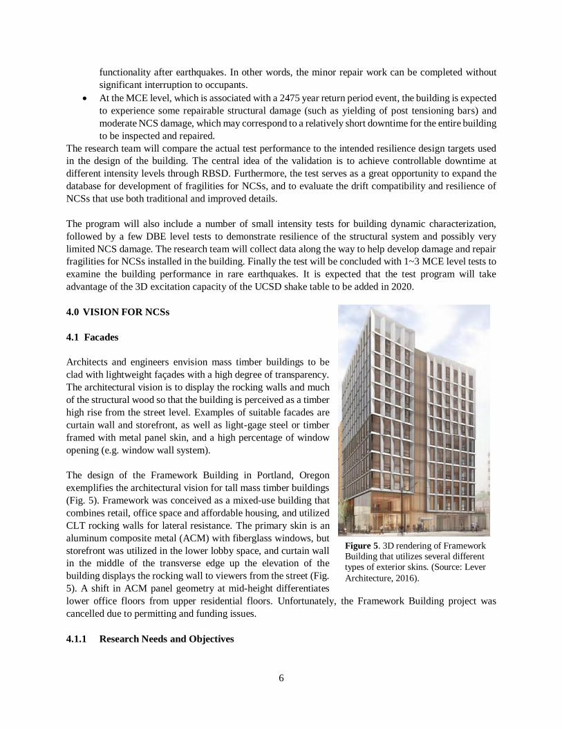
The design of the Framework Building in Portland, Oregon
exemplifies the architectural vision for tall mass timber buildings
(Fig. 5). Framework was conceived as a mixed-use building that
combines retail, office space and affordable housing, and utilized
CLT rocking walls for lateral resistance. The primary skin is an
aluminum composite metal (ACM) with fiberglass windows, but
storefront was utilized in the lower lobby space, and curtain wall
in the middle of the transverse edge up the elevation of the
building displays the rocking wall to viewers from the street (Fig.
5). A shift in ACM panel geometry at mid-height differentiates
lower office floors from upper residential floors. Unfortunately, the Framework Building project was
cancelled due to permitting and funding issues.
4.1.1 Research Needs and Objectives
Figure 5. 3D rendering of Framework
Building that utilizes several different
types of exterior skins. (Source: Lever
Architecture, 2016).

7
Buildings in earthquake zones generally absorb the earthquake accelerations by relative movement of the
structural frame between the stories; exterior skin systems are also subjected to this interstory movement,
and thus must “go along for the ride”. Design codes require demonstration (e.g. racking tests of exterior
skin mockups) that curtain walls and other glass-infill systems can sustain the design lateral interstory drift
without glass fallout. However, such systems are routinely damaged (Evans et al. 1988; Filiatrault et al.
2001; Miranda et al. 2012; Baird et al 2012). For example, glass damage was extensive in the 1994
Northridge Earthquake, despite other NCS damage being limited (Reitherman and Sabol 1995). Notably,
rubber gaskets in mechanically captured systems were dislodged and caused a consistent breach in water
tightness in buildings (Harter 1994). Recently, following the 2011 Christchurch earthquake, 25% of curtain
wall systems were non-operational (Baird et al. 2012). Reconnaissance data does not elucidate why glass
damage is so common in spite of the robustness of modern designs. The majority of failures may be in
vulnerable systems or affected by boundary details with adjacent systems, however, details of individual
failures are not known or well understood.
Industry standard in-plane static and dynamic racking tests of full-size curtain wall and storefront mock-up
specimens are used to validate seismic drift capacity. This static test (AAMA 501.4) is the industry standard
for serviceability, and specifies a sequence of tests including air and water penetration before and after 3
cycles of static loading (racking) to a target drift level, e.g. 1% (AAMA 2018a). The displacement sustained
without glass fallout, or Δfallout, can be experimentally determined using the AAMA 501.6 dynamic racking
protocol (AAMA 2018b). ASCE 7-16 (2016) specifies that for any glazed system, Δfallout 1.25DplIe, where
Dpl = design relative story displacement and Ie = importance factor. Given the high rate of glass cracking
and failure in the field, the AAMA testing protocol may not represent the seismic response of curtain walls
and other glazed systems in field conditions. Seismic performance of curtain walls may be affected by:
interaction between in-plane and out-of-plane movement, interaction between panels, flexure or vertical
vibration at structural attachment points, high frequency vibrations or diverse frequency content of motion
inherent in a multi-modal system, and boundary conditions between different façade types. Large-scale 3D
shake table testing offers the opportunity to incorporate some of these more realistic field conditions, but
shake table tests of curtain walls and glazed systems are extremely limited (Ma and Yan 1998, Wang et al.
2002, Lu et al. 2010). Thus, a performance comparison of similar specimens tested under the AAMA 501.6
loading protocol and shake table testing is needed. Equally important, ASCE 7-16 does not have a
serviceability requirement, but California Building Code Section 2410 (CBSC 2016), used for critical
emergency response buildings, requires that structurally glazed systems demonstrate serviceability at the
design drift. Confirming that an AAMA 501.6 compliant design can maintain serviceability after a shake
table test is important for continued functionality in the proposed new immediate occupancy performance
objective (Sattar et al., 2018).
The research objectives related to façade testing in the present program are: (1) Evaluate the seismic
performance of glazed facades in the context of the design methodology and performance targets to achieve
seismic resilience; (2) evaluate the relative performance of glazed systems with different details, including
any proposed detailing improvements, to identify systems best suited to meeting performance targets for
seismic resilience; (3) validate AAMA 501.4 and 501.6 racking protocols for system qualification to
represent the seismic performance of curtain walls and other glazed systems.
4.1.2 Preliminary Plans
The vision for this project is to clad portions of the building with a variety of different skin systems provided
by different industry suppliers, i.e. the “patchwork quilt” approach. Suppliers may select a portion of the

8
exterior to install their systems. Suppliers are encouraged to put forth innovative details that may improve
the seismic performance. As a priority objective is to understand and evaluate the performance of individual
systems/details, interactions between varying skin systems will be avoided. Thus, the building will not be
fully clad and will not need boundary joints between different skin systems. Based on story height, footprint
dimensions and rocking wall locations, the building will have about 10,000 sf of usable exterior skin area.
Individual subassemblies on the order of 500–2000 sf are considered desirable. Figure 6 illustrates different
possible configurations for individual skin subassemblies that vary from about 200-250 sf per story.
Table 2 provides a list of general type of skin systems and
detailing variations that are desired to be incorporated
into the test program. The desired facades can be
classified into one of two basic types of systems: glazed
curtain wall, and light-frame systems with windows.
With regard to curtain walls, stick-built and unitized are
constructed distinctly and have the distinct mechanisms
(rack versus sway) for accommodating the inter-story
drift; thus comparing their performance is of great
interest. Among light-frames systems, steel stud framing
with metal panel finish are of great interest, with
recognition of the myriad of options available on the
market for metal panels. One of the unique aspects of this
project is assessing the performance of the glass during
3D shaking, including the ability of the system to resist
glass cracking or fallout under intermediate and large
drift levels. As such, the proposed glass variations with
regard to aspect ratio, glass treatment and glass type can
be pursued across both curtain walls and light-framing with window openings. The research team is actively
pursuing material donations and other in-kind contributions to support investigations of each of these types
of promising systems.
The plan sketches (Figs. 1 and 6) show that the CLT floor beams are set back from the plan edge and that
floor diaphragms are cantilevered over the edge of the floor beams for the skin subassembly regions denoted
in Fig. 6. Thus, the CLT floor diaphragms will be utilized for anchoring the exterior skins. As mentioned
in Section 2.2, 5-ply (6.875” thick) CLT is anticipated for this purpose. A top of slab lag bolt anchor is
envisioned for hanging the curtain walls. Platform framed systems are easily supported between the floor
diaphragms, while a balloon framed system could be supported by installation of perimeter joists.
Table 2. Skins systems and detailing variations desired for the test program
Basic Skin System Class of Variation Variations Considered
Storefront Glazing method Mechanically captured vs structurally glazed
Curtain wall w/ glazing Glass aspect ratio Varied from 1:2 to 2:1
Stick built curtain wall Glass treatment Heat strengthened vs. fully annealed
Unitized curtain wall Glass type Laminated and insulating glass units (IGU)
Light-framed with windows Framing style Balloon vs platform framed
Light gage steel stud framing Finish material Metal panel, wood shingle, and stucco
Wood stud framing Window type Fixed or operable, variable size
Window framing Metal or wood framed
Glass variations Same variables as for curtain walls may be applied
Figure 6. Potential subassembly configurations
for testing different skin systems

9
4.2 Stairs
In the event of power loss during an earthquake, stair systems serve as the sole means of human egress and
ingress. Moreover, the continued function of the stairs during the shake table test program will be critical
to support access to all floors of the building to inspect damage after each test. The proposed building layout
(Fig. 2) includes one scissor staircase per floor, stacked up on all floors of the building. The architectural
vision for the tall mass timber buildings would utilize lightweight prefabricated stairs built from steel, wood,
or a hybrid combination of the two for an aesthetic match to the building architecture.
4.2.1 Research Needs and Objectives
Scissor stairs are susceptible to twisting as their structural form rises in elevation. Steel stairs tend to be
lighter and more deformable than other commonly used reinforced concrete stairs. Although stairs are
assigned an importance factor Ip = 1.5, catastrophic behavior has been documented in past earthquakes (e.g.
Roha et al. 1982; Bull 2011; Kam and Pampanin 2011; Li and Mosalam 2013). For example, collapse of
stair systems in New Zealand during the 2011 Christchurch earthquake precluded occupant safe egress from
three high rise buildings in the business district. The most prominent mechanisms that have led to stair
failure are described in Bull (2011). Appreciable interstory drift along the strong axis of the stair system
may lead to: 1) compression or shortening of a straight stair system resulting in an opening ‘knee failure’
or 2) extension, which can lead to stairs sliding off their support if insufficient width is provided. Interstory
drift transverse to the stair primary axis causes bending and shear in the plane of the stairs, which also has
led to significant damage observations in the field. Finally, scissor stairs are especially susceptible to
twisting and torsional displacements due to their mid-height landing and high asymmetry. The experience
in Christchurch prompted immediate changes to New Zealand design provisions for stairs (SESOC 2011)
that require fixing a stair’s top connection, and allowing a sliding base connection or sliding at mid-height
in the case of scissor stairs, where sliding displacements are to be designed for 1.5 times the ultimate limit
displacements. These modern design and detailing guidelines have not been tested to validate their
effectiveness.
Numerical studies have been focused on quantifying the influence of stair systems on the overall building
response (e.g. Cosenza et al. 2008; Tegos et al. 2013), while coupled numerical analyses involved
comparisons of response with and without stairs to elicit the impact of the presence of stairs. Such
simulations have been limited to considering elastic response of the stairs, though inelastic response could
occur under large earthquakes. A few experimental programs have been conducted on stair subsystems
(Higgins 2009; Black et al. 2017). In the latter test program, stairs fixed at one end, and partial freedom at
the opposing end were tested and demonstrated promise to minimize drift induced damage. While these
tests do offer understanding of the stair subsystem performance, they do not elicit interaction with their
supporting structure. However, a few full-scale building tests have incorporated stairs. In a previous large
scale building test, prefabricated steel stairs were damaged at interstory drift levels well below the building
design performance targets (~0.75%), including weld fracture at flight-support locations (Wang et al. 2015).
The design details in these tests were intended to provide ductility, but rather demonstrated inadequate load
path continuity precipitated by premature weld failure.
The research objectives related to stairs testing in the present program are: (1) Evaluate the seismic
performance of stairs in the context of the design methodology and performance targets to achieve seismic
resilience; and (2) further develop and validate approaches to protect stairs from drift-induced damage.
Evolving solutions isolate the stairs from the drift demands through a free connection at one floor level.

10
4.2.2 Preliminary Plans
Donations from industry are sought to incorporate a variety of lightweight stairs built from different
materials and with different support conditions. Desired stair support systems utilize wood carriages and
stringers or steel stringers. The treads may be finish wood flooring over plywood, steel pan treads with
concrete fill, flat plate treads with textured top surfaces, or bar grating treads; paired with wood or steel risers. Open riser configurations are also of interest.
Solutions that are under development for stairs aim to isolate the stairs from the drift demands through a free (slotted or sliding) connection at one floor level. To test these solutions, a fixed connection may be
utilized for the stair to top landing connection, while a free or deformation compatible connection may be
incorporated at the stair to bottom-landing connection. Thus, it is envisioned that new deformation compatible bottom landing connections (fixed-free) are compared with traditional fixed-fixed connections.
These configurations should be dispersed throughout the building to capitalize on the variation of drift and
acceleration demands. Table 3 presents a possible selection matrix to combine the different possible
variations for the stairs. Fixed-free connections are utilized on the stories with the largest expected drift demands (predicted to be the lowest stories) to minimize damage and preserve building access throughout
the test program.
Table 3. Selection matrix for stair detail variations
Story Stair Support Tread and Riser Boundary Conditions
1 steel steel treads with concrete-fill fix-free
2 steel wood fix-free
3 wood wood fix-free
4 steel steel treads with concrete-fill fix-fix
5 steel wood fix-fix
6 wood wood fix-free
7 steel steel bar grating treads fix-fix
8 steel steel flat plate treads fix-free
9 steel wood, open riser fix-fix
10 steel wood, open riser fix-free
4.3 Other NCSs
Also of interest to the team are interior partition walls, suspended ceilings, and piping/mechanical
equipment. The performance of these NCSs is impacted by their interactions. Unlike stairs and facades,
extensive experimental and analytical research has already been conducted on many of these NCSs, such
that their performance has been rigorously quantified, and the major vulnerabilities have been identified.
Thus, this test is an opportunity to test detailing improvements that have potential to eliminate or reduce
some sources of component damage in small to moderate level shaking.
4.3.1 Research Needs and Objectives
Interior partition walls are drift sensitive and incur significant damage at relatively low levels of drift
(Retamales et al. 2013). One study (Almufti and Willford 2013) concluded that preventing damage in non-
load bearing walls is the key to resilience for low-to-mid seismic hazard levels. Damage-reducing details
have been developed, such as including the gaps at wall boundaries, sliding “slip-track” or friction
connections, and enhanced strength connections for weaker structural systems (Araya-Letelier and

11
Miranda, 2012, Retamales et al. 2013, Tasligedik et al. 2013, Swenson et al. 2015). Even walls with the
slip track detailing incur damage at intersecting walls, because the attached intersecting wall cannot slip in
the out-of-plane direction, or at wall ends when sheathing over the slip-plane. Fire-rated detailing, which is
an important design consideration in tall timber buildings, generally requires that exposed steel and timber
be covered. This requirement, unfortunately, is at odds with many of the current ideas for resilient
nonstructural walls that aim to somewhat isolate the partition wall from the interstory drift as well as
accommodate some deformation in the wall through gapping.
Nonstructural walls with improved details were recently tested in bidirectional subassembly tests at Lehigh
University. In the first test, a planar wall with double deflection or telescoping slip track (nested top tracks
with a vertical gap usually used for accommodating vertical deflection) was compared to an identical wall
with conventional slip track detailing (Fig. 7(a) and (b)). In the second test, the response of two C-shaped
walls with different gap details were evaluated: a corner gap detail at the intersecting walls, and a distributed
expansion gap detail (Figs. 7(c)). The gaps were intended to reduce damage at the wall intersections. While
the results are still being analyzed, preliminary observations suggest the following. The telescoping detail
improves performance over the traditional slip track, especially at wall ends where the studs and track can
become disconnected under deflection. Both the distributed gap and corner gap details delayed the onset of
damage to about 1% drift (with the exception of one distributed gap expansion joint that suffered some
premature cosmetic damage). With the distributed gap detail, the small gaps directly adjacent to the
intersection are the most effective at absorbing relative drift, thus, lengthening these gaps might further
delay the onset of damage. One drawback of the gap strategy is the risk that the gaps open completely at
large drifts, thus allowing for portions of the wall to separate. This could lead to isolated wall segments
being at risk of collapse under large drifts, which could outweigh the gains of delayed damage onset.
Figure 7. (a) Telescoping connection detail, (b) slip track connection detail, (c) C-shaped wall with corner gaps
(top) and distributed gaps (bottom).
(a)
(b)
(c)

12
Fire protection of the CLT rocking walls is another issue of importance. Building code regulations will
typically require that some CLT walls be sheathed with gypsum wall board (GWB) for fire protection, to
limit the total amount of exposed wood. In this case, standard architectural detailing would involve
sheathing directly over the wall and boundary columns with three or four layers of GWB. However, this
detail would not accommodate wall uplift and rocking, and relative movement between the walls and
boundary columns. It is expected that the GWB would tear apart and induce significant damage. The project
team has discussed other fire protection detailing, such as introducing a gap with a fire retardant
impregnated foam.
Suspended ceilings are frequently used in commercial buildings to provide soundproofing, fire protection,
and cover mechanical equipment, wiring and plumbing in the plenum region. Suspended ceilings consist
of a horizontal grid system of main tees and cross tees with lay-in tiles, and supported at select locations by
vertical hanger wires. In the U.S., suspended ceilings covering more than 1000 sf area between boundary
walls are required to have seismic bracing, which consists of compression posts and diagonal splay wires.
As typical boundary conditions, the ceiling is fixed to the perimeter walls along two adjacent edges, and
floating with a small gap on the opposite two edges.
Typical damage to suspended ceilings is discussed in Soroushian et al. (2016), as determined from 3 major
experiments. During large intensity shaking, ceiling panels are routinely dislodged and some panels may
fall to the floor. As shaking intensity increases, several grid connections may fail in a localized area causing
portions of the ceiling to collapse. This behavior is often instigated by pounding of the ceiling system at the
wall boundaries. Pop rivets and seismic clips installed at the boundaries suffer failures at relatively low
levels of shaking. In addition, a shake table test at E-Defense led to the conclusion that suspended ceilings
with seismic bracing are very susceptible to damage from the vertical component of shaking, because the
rigid bracing drives the ceiling grid system to move with the floor above (Soroushian et al. 2015).
To improve the resilience of suspended ceilings, Pourali et al. (2017) have proposed the concept of a
floating ceiling. Compared to the conventional fixed-floating boundary, the floating ceiling is installed with
a sizable gap between the ceiling edge and perimeter walls on all sides, and no seismic bracing so that the
ceiling is a fully suspended system that vibrates as a pendulum, with vibration frequency determined by the
length of the hanger wires. A series of tests on floating ceilings were conducted at University of Canterbury
(Pourali et al. 2017), and the specimens were subjected to both sinusoidal and earthquake loading. It was
shown that maintaining a completely floating ceiling is unrealistic due to large displacements that led to
perimeter gap closure, and subsequent significant acceleration amplifications of the ceiling. As a result,
another configuration with an acoustic isolation foam placed between the ceiling and the boundary walls
was tested. The foam was effective to mitigate the effect of pounding and reduce the seismic displacements,
but acceleration amplification actually increased. The concept may have some potential for a resilient
ceiling system if a balance can be achieved between utilizing the pendulum behavior while controlling the
displacement demands.
The project team proposes another low damage solution for ceiling systems for consideration in the test
program. Dislodged ceiling tiles are generally observed at relatively low shaking intensities, before any
other damage. While dislodged tiles are easily restored, the temporary dislodgement disrupts the integrity
of the suspended ceiling system, leaving the grid framing susceptible to other damage states. One idea is to
explore the use of magnets to secure the ceiling tiles to the grid members as a defense against dislodging.
Also, as mentioned above, the authors observed that under current detailing (Fig. 8(a)), rigid seismic bracing
caused the ceiling system to move rigidly with the floor in the vertical direction, which led to dislodgement

13
of numerous ceiling tiles. A new detail for seismic bracing is proposed that uses shallow angle splay wires
to connect the compression posts to the ceiling grid (Fig. 8(b)) (Souroushian 2019). This detail is envisioned
to maintain the function of the bracing in the horizontal direction while separating the suspended ceiling
from the floor above in the vertical direction, and thus reducing the vertical demands to the system.
Several tests have been conducted on suspended ceilings integrated with sprinkler piping (Soroushian et al.
2015; Jenkins et al. 2017). However, a knowledge gap exists with regard to mechanical equipment in the
plenum region. Dynamic response of above-anchored equipment such as air handlers should be quantified
under realistic 3D shaking. Furthermore, displacement compatibility of main equipment units and
connecting HVAC ducts should be evaluated. These lightweight ducts are often installed with very limited
bracing. Finally, the compatibility of the seismic response of the mechanical equipment and suspended
ceiling system should be experimentally evaluated for undesirable interactions, leading potentially to new
solutions that consider the integrated design of the systems.
4.3.2 Preliminary Plans
Preliminary plans are to fabricate and test partition walls on a minimum of two floors and suspended
ceilings on a minimum of two floors. This would permit some of the detailing variations discussed above
to be explored while limiting the required resources for testing. Two options will be considered: 1)
integrated partition walls and suspended ceilings on the same floors, or 2) partition walls and suspended
ceilings installed on separate floors. The decision depends on the test objectives for each system. For
instance, if the main focus of the suspended ceiling tests is to evaluate new detailing, omitting partition
walls to allow for larger open plan area best supports this objective. However, partition walls should be
installed around the plan boundary in the absence of exterior skins. Under option 1 (integrated partition
walls and ceilings), it is proposed to install these NCSs on one lower level (subjected to higher drift
demands) and one upper level (subjected to higher acceleration demands). Under option 2 (separate
partition walls and ceilings), it is proposed to install the partition walls in adjacent lower floors (subjected
to similar and larger drift demands) and the ceilings in adjacent upper level floors (subjected to similar and
larger acceleration demands).
Piping and/or mechanical equipment may be added as resources permit. Again, these systems may be
integrated with suspended ceilings or installed in isolation depending on the determined objectives. New
details for suspended ceilings or equipment installation should first be tested in isolation. However, an
integrated design and test to evaluate interaction between components is desirable if the response of the
components in isolation is well-established.
5.0 SUMMARY
Figure 8. (a) Current and (b) proposed seismic bracing detail for suspended ceilings (Soroushian, 2019)
14
Preliminary plans for a seismic shake table test of a 10-story mass timber building have been described.
The building is constructed with glulam beams and columns, CLT floor diaphragms, and post-tensioned
CLT rocking walls. The overall test objective is to validate the design methodology for seismically resilient
timber buildings. The response of NCSs are critical to resilience, and the timber specimen offers a testbed
to evaluate existing and improved detailing strategies for many types of NCSs. This is an exciting
opportunity to advance the state-of-the-art in NCS analysis and design. A vision for NCS testing has been
presented; however, payload projects to advance alternative objectives will be entertained.
The testing will take place at the NHERI@UC San Diego outdoor shaking table after its upgrade to allow
input of 6 degree-of-freedom input motions. Construction of the specimen will commence in spring of 2021,
and testing is planned over the summer of 2021. The project team is actively seeking industry and academic
collaborators for testing of various NCSs. Currently, the following types of contributions are needed:
material donations; fabrication and disassembly; and in-kind engineering design, analysis and data
synthesis.
6.0 ACKNOWLEDGEMENT
This research project is supported by the National Science Foundation through a number of collaborative
awards, including CMMI 1636164, CMMI 1634204, CMMI 1635363, CMMI 1635227, CMMI 1635156,
and CMMI 1634628, and by the US Forest Service through Grant No. 19-DG-11046000-616. The use of
the NHERI experimental facility is supported by the National Science Foundation’s Natural Hazards
Engineering Research Infrastructure (NHERI) Program. The authors are grateful for this support. The
opinions, findings and conclusions/recommendations expressed herein are those of the authors alone and
do not represent the views of the National Science Foundation or the US Forest Service.
7.0 REFERENCES
Almufti, I. and Willford, M. (2013). REDi Rating System: Resilience-based Earthquake Design Initiative
for the Next Generation of Buildings.
http://publications.arup.com/Publications/R/REDi_Rating_System.aspx [Accessed 7/23/2014].
American Architectural Manufacturers Association (AAMA), (2018a). Recommended Static Test Method
for Evaluating Window Wall, Curtain Wall and Storefront Systems to Seismic and Wind-Induced Inter-
Story Drift, Publication No. AAMA 501.4-18.
American Architectural Manufacturers Association (AAMA), (2018b). Recommended Dynamic Test
Method for Determining the Seismic Drift Causing Glass Fallout from Window Wall, Curtain Wall and
Storefront Systems, Publication No. AAMA 501.6-18.
American Wood Council (2015). “National Design Specification for Wood Construction with
Commentary, 2015 Edition.
Araya-Letelier G, Miranda E. (2012). “Novel sliding/frictional connections for improved seismic performance of gypsum wallboard partitions”. In 15th World Conference on Earthquake Engineering,
Portuguese Society of Earthquake Engineering, Lisbon, Portugal.

15
Baird, A., Palermo, A., Pampanin, S. (2012). “Façade damage assessment of multi-story buildings in the 2011 Christchurch Earthquake”, Bulletin of the New Zealand Society for Earthquake Engineering,
44(4):368-376.
Black, C., Aiken, I., Smith, K., Belvin, R., Peachey, A. (2017). Seismically-resilient stair systems for
buildings. In the Proceedings of the Structural Engineers Association Annual Convention. Paper #22.
San Diego, California. September.
Bull D.K. (2011). Stair and Access Ramps Between Floors in Multi-storey Buildings, A report of the
Canterbury Earthquakes Royal Commission: Christchurch, New Zealand.
California Building Standards Commission (CBSC) (2016). California Building Standards Code - Part 2
(volume 2; section 2410). International Code Council.
Cosenza, E., Verderame, G. M., and Zambrano, A. (2008). “Seismic performance of stairs in the existing reinforced concrete building.” Proc., 14th World Conference on Earthquake Engineering, Beijing,
China.
Evans, E., Kennett, W. T. Holmes and F. J. L. Ramirez (1988). “Glass damage in the September 19. 1985
Mexico City earthquake”, Report prepared for NSF, CES-861093.
Filiatrault, A., Uang, C-M., Folz, B., Christopoulos, C., and Gatto, K. (2001). Reconnaissance Report of
the February 28, 2001 Nisqually (Seattle-Olympia) Earthquake, Structural Systems Research Project
Report No. SSRP-2000/15, University of California, San Diego, La Jolla, CA.
Harter, D. (1994). “Earthquake in Los Angeles. Glazing,” California Glass Association.
Higgins, C. (2009). “Prefabricated steel stair performance under combined seismic and gravity loads.”
ASCE Journal of Structural Engineering, 135(2), 122–129.
Jenkins, C., Soroushian, S., Rahmanishamsi, E., & Maragakis, E. M. (2017). “Experimental fragility
analysis of pressurized fire sprinkler piping systems”, Journal of Earthquake Engineering, 21(1), 62-86.
Kam, W.Y., Pampanin, S. (2011). The seismic performance of RC buildings in the 22 February 2011
Christchurch earthquake. Structural Concrete. 124:223–233.
Lever Architecture (2016). Personal Communication.
Li B. and Mosalam K.M. (2013). Seismic performance of reinforced-concrete stairways during the 2008
Wenchuan earthquake. ASCE Journal of Performance of Constructed Facilities. 276:721–730.
Lu, W., Huang, B., Cao, W. (2010). “Study on the shaking table test of micro crystal glass curtain wall”,
Build Struct 40(1):59–61. [in Chinese].
Ma, C. and Yan, D. (1998). “Cyclic loading and shaking table testing of the hidden framed glass curtain
wall”, Build Struct 3:54–57. [in Chinese].
Miranda, E., Mosqueda, G., Retamales, R., and Pekcan, Gokhan (2012). Performance of nonstructural
components during the 27 February 2010 Chile earthquake, Earthquake Spectra 28 (S1), S453– S471.
Pei, S., van de Lindt, J. W., Barbosa, A. R., Berman, J. W., McDonnell, E., Daniel Dolan, J., Blomgren, H.E., Zimmerman, R., Huang, D, Wichman, S. (2019a). “Experimental Seismic Response of a Resilient
2-Story Mass-Timber Building with Post-Tensioned Rocking Walls.” Journal of Structural
Engineering, 145(11), 04019120.
Pei, S., Ryan, K., van de Lindt, J., Barbosa, A., Ricles, J., Dolan, J. D., Berman, J., Sause, R., Griesenauer,
D., Furley, J., Wichman, S. (2019b). “Shake Table Test of A Two-story Mass Timber Building with
Post-tensioned Rocking Walls.” DesignSafe-CI. https://doi.org/10.17603/ds2-k3y4-y384.

16
Pourali, A., Dhakal, R. P., MacRae, G., & Tasligedik, A. S. (2017). “Fully Floating Suspended Ceiling System: Experimental Evaluation of Structural Feasibility and Challenges.” Earthquake Spectra, 33(4),
1627-1654.
Reitherman, R., and Sabol, T. (1995). “Nonstructural Damage,” in John Hall, (ed.), Northridge Earthquake
of January 17, 1994 Reconnaissance Report, Earthquake Spectra, Vol. 11, Supplement C, Earthquake
Engineering Research Institute, Oakland, CA.
Retamales, R., Davies, R., Mosqueda, G., Filiatrault, A. (2013). “Experimental seismic fragility of cold-
formed steel framed gypsum partition walls”, Journal of Structural Engineering (ASCE), 139(8):1285-
1293.
Roha C, Axley JW, Bertero VV. (1982). The performance of stairways in earthquakes. Technical Report
UCB/EERC-82/15, Earthquake Engineering Research Center, University of California, Berkeley:
Berkeley, CA.
Sattar, S., McAllister, T.P., McCabe, S.L., Johnson, K.J., Segura, C.L., Clavin, C., Fing, J.F., Levitan, M.L.,
and Harrison, K.W. (2018). Research Needs to Support Immediate Occupancy Building Performance
Objective Following Natural Hazard Events. National Institute of Standards and Technology Special Publication (NIST SP-1224) U.S. Department of Commerce. Accessed at:
doi.org/10.6028/NIST.SP.1224.
Soroushian, S., Maragakis, E. M., Ryan, K. L., Sato, E., Sasaki, T., Okazaki, T., & Mosqueda, G. (2015). “Seismic simulation of an integrated ceiling-partition wall-piping system at E-Defense. II: evaluation of
nonstructural damage and fragilities”. Journal of Structural Engineering, 142(2), 04015131.
Soroushian, S., Rahmanishamsi, E., Ryu, K. P., Maragakis, M., & Reinhorn, A. M. (2016). “Experimental
fragility analysis of suspension ceiling systems”. Earthquake Spectra, 32(2), 881-908.
Soroushian, S. (2019). Personal Communication.
Structural Engineering Society New Zealand (SESOC) (2011). Practice Note: Design of Conventional
Structural Systems Following the Canterbury Earthquakes, New Zealand. Version 4-21, December.
Swenson, S., Deierlein, G.G., Miranda, E. (2015). “Behavior of screw and adhesive connections to gypsum
wallboard in wood and cold-formed steel-framed wallettes”, Journal of Structural Engineering (ASCE),
E4015002-1-11. DOI: 10.1061/(ASCE)ST.1943-541X.0001307
Tasligedik AS, Pampanin S, Palermo A. (2013). “Low damage seismic solutions for non-structural drywall
partitions.” In Vienna Congress on Recent Advances in Earthquake Engineering and Structural
Dynamics 2013 (VEESD 2013). DOI: 10.1007/s10518-014-9654-5.
Tegos, I. A., Panoskaltsis, V. P., and Tegou, S. D. (2013). “Analysis and design of staircases against seismic loadings.” Proc., 4th ECCOMAS Thematic Conference on Computational Methods in Structural
Dynamics and Earthquake Engineering, Kos Island, Greece.
Wang, C., Xiao, C., and Zhao, X. (2002). “Seismic performance test of the curtain wall”, Build Struct
32(9):65–67. [in Chinese].
Wang, X., Astroza, R., Hutchinson, T.C., Conte, J.P., and Restrepo, J.I. (2015). “Dynamic characteristics
and seismic behavior of prefabricated steel stairs in a full-scale five-story building shake table test
program.” Earthquake Engineering & Structural Dynamics, 44(14), 2507-2527.