setup of the system - ferroli.com · setup of the system the unit should be configured by the...
TRANSCRIPT

30
SETUP OF THE SYSTEM
The unit should be configured by the installer to be able to properly handle all elements of the system, depending on the application climate and the users' requests . Various settings are available . These settings are accessible and programmable through the "FOR SERVICEMAN" menu .
"FOR SEVICEMAN" menu - italian language

31
SETUP OF THE SYSTEM

32
SETUP OF THE SYSTEM

33
SETUP OF THE SYSTEM

34
SETUP OF THE SYSTEM
"FOR SEVICEMAN" menu - english language

35
SETUP OF THE SYSTEM

36
SETUP OF THE SYSTEM

37
SETUP OF THE SYSTEM

38
SETUP OF THE SYSTEM
How to go to FOR SERVICEMAN
Go to MENU> FOR SERVICEMAN . Press OK
The password is 666. Use ◄ ► to navigate and use ▼ ▲ to adjust the numerical value. Press OK. The following page is displayed:
Use ▼ ▲ to scroll and use “ok” to enter submenu for setting the parameters.
FOR SERVICEMAN
Please input the password:
ADJUST SCROLLENTEROK
0 0 0
FOR SERVICEMAN
2. COOL MODE SETTING3. HEAT MODE SETTING4. AUTO MODE SETTING5. TEMP.TYPE SETTING6. ROOM THERMOSTAT7. OTHER HEATING SOURCE
1. DHW MODE SETTING
SCROLLENTEROK
FOR SERVICEMAN
9. ECO/COMFORT MODE SETTING10. SERVICE CALL SETTING11. INITALIZE MANUALLY12. TEST RUN13. SPECIAL FUNCTION14. AUTO RESTART
8. HOLIDAY AWAY MODE SETTING
SCROLLENTEROK
Description of terms The terms related to this unit are shown in the table below
Parameter DescriptionT1 Outlet water temperature of the unit or of the backup heater (if installed)
T1B Outlet water temperature sent to the system (in case of additional heating source as a gas boiler is installed)
T1S Target outlet water temperatureT2 Temperature of refrigerant at outlet/inlet of plate heat exchanger when in heat mode/cool mode
T2B Temperature of refrigerant at inlet/outlet of plate heat exchanger when in heat mode/cool modeT3 Temperature of tube at outlet/inlet of condenser when in cool/heat modeT4 Outdoor air temperatureT5 Temperature of domestic hot water (misured by the temperature probe installed on the DHW tank)Th Refrigerant suction temperatureTp Refrigerant discharge temperature
TW_in Inlet water temperature of plate heat exchangerTW_out Outlet water temperature of plate heat exchanger
AHS Additional heating source (for example a gas boiler)IBH1 The first stage of the backup heater (if installed)IBH2 The second stage of the backup heater (if installed)TBH Backup heater in the domestic hot water tank (if installed)Pe Refrigerant evaporate/condense pressure in cool/heat mode
ON/OFF by digital input or switch .(refer to room thermostat)COOL/HEAT mode managment by digital input . (refer to room thermostat)
NOTA

39
SETUP OF THE SYSTEM
Use ◄ ►and ▼▲ to scroll and adjust parameters. Use BACK to exit.
dT5_ON is the temperature difference for starting the heat pump, the picture below illustrates the dT5_ON function .
T5S is the target temperature for domestic hot water . T5 is the actual temperature of domestic hot water . When T5 drops to a certain temperature (T5≤T5S-dT5_ON) the heat pump will be available . dT1S5 is the correct value for the target outlet water temperature (T1S=T5+dT1S5) .
T4DHWMAX is the maximum outdoor air temperature that the heat pump can operate at for domestic water heating . The unit will not operate if the outdoor air temperature goes above it in DHW mode .
DHW mode setting
DHW:domestic hot waterDHW MODE SETTING typically consists of the following:1 . DHW MODE: enable or disable the DHW mode2 . TANK HEATER: set whether the booster heater is available or not3 . DISINFECT: set the parameters for disinfection4 . DHW PRIORITY: set the priority between domestic hot water heating and space operation5 . DHW PUMP: set the parameters for DHW pump operation . The functions above apply only to installations with a domestic hot water tank .
How to set the DHW mode
To determine whether the DHW mode is effective . Go to MENU> FOR SERVICEMAN> DHW MODE SETTING . Press OK . The following page is displayed:
Use ◄ ► to scroll and OK for enter. When the cursor is on press YES, Press OK to set the DHW MODE as effective . When the cursor is on NON,press OK to set the DHW MODE as ineffective .
1 DHW MODE SETTING
1.2. TANK HEATER1.3. DISINFECT1.4. DHW PRIORITY1.5. DHW PUMP
1.1. DHW MODE
SCROLLENTEROK
YESYESYESYESYES
NONNONNONNONNON
1 . Go to MENU> FOR SERVICEMAN>DHW MODE SETTING>1 .1 DHW MODE 1.1 DHW MODEdT5_ONdT1S5T4DHWMAXT4DHWMINt INTERVAL DHW
5°C10°C43°C
-10°C5 MIN
SCROLL
T5S
T5
T5S-dT5_ON
Compressor OFF ON OFF
T4DHWMIN is the minimum outdoor air temperature that the heat pump can operate for domestic water heating . The heat pump will turn off if the outdoor air temperature drops below it in water heating mode . The relationship between operation of the unit and outdoor air temperature can be illustrated in the picture below:
Heat by TBH or AHS Heat by heat pump T4OFF
T4DHWMAXT4DHWMINT4DHWMIN
Heat by TBH or AHS Heat by heat pump
T4DHWMAX
If DHW MODE is set "NON", the function is not available and so could not be selected by the user .
NOTE
T_INTERVAL_DHW is the start time interval of the compressor in DHW mode . When the compressor stops running, the next time the compressor turns on it should be T_INTERVAL_DHW plus one minute later at least .

40
SETUP OF THE SYSTEM
Tank heater (electrical heater for DHW tank)
If tank heater (booster heater) is avaliable, Go to FOR SERVICEMAN >DHW MODE SET-TING>1 .2 TANK HEATER and select “Yes”, when “OK” pressed, the following page will appear:
Disinfect
To enable disinfect function,Go to MENU> FOR SERVICEMAN>DHW MODE SETTING>1 .3 DISINFECT and select “YES”, when “OK” pressed, the following page will appear .
T5S_DI is the target temperature of water in the domestic hot water tank in the DISINFECT function.t_DI_HIGHTEMP is the time that the hot water will last.
t_DI_MAX is the time that disinfection will last. The change of domestic water temperature is described in the picture below:
Be aware that the domestic hot water temperature at the hot water tap will be equal to the value selected in FOR SERVICEMAN “T5S_DI” after a disinfection operation.
Use ◄ ► and ▼▲ to scroll and adjust parameters. Use BACK to exit.
dT5_TBH_OFF is the temperature difference between T5 and T5S that turns the booster heater off . The booster heater will turn off (T5≥T5S+dT_TBH_OFF) when the heat pump malfunctions.
T4_TBH_ON is the temperature only when the outdoor air temperature is lower than its parameter and the booster heater will be available .t_TBH_DELAY is the time that the compressor has run before starting the booster heater (if T5<min (T5S,T5stop)) .The operation of the unit during DHW mode described in the picture below:
In the picture, T5stop is a parameter related to outdoor air temperature, which cannot be changed in the user interface . When T5≥T5stop, the heat pump will turn off.
Note: If the booster heater is unavailable (1 .2 TANK HEATER NON is selected), the dT5_ON cannot be adjusted and is fixed at 2.
1.2 TANK HEATERdT5 TBH OFFT4_TBH_ON_TBH_DELAY
5°C20°C
90 MIN
SCROLL
COMP.
min(T5S,T5stop)-dT5_on
t_TBH_delay
TBH
T5stopT5S
T5
TimeOFF
ONOFF
ONOFF
T5S+dT5_TBH_OFF
1.3 DISINFECTT5S_DIt_DI_HIGHTMEP.t_DI_MAX
5°C30 MIN
120 MIN
SCROLL
t
T5
T5S_DI
T5S
t_DI_HIGHTEMP
t_DI_MAX
NOTE
The booster heater of DHW tank (THB) and backup heater of the system (electrical booster IBH) can’t operate simulta-neously, if the booster heater has been on, the backup heater will be off and viceversa .

41
If this high domestic hot water temperature can be a potential risk for human injuries, a mixing valve (field supply) should be installed at the hot water outlet connection of the domestic hot water tank . This mixing valve will ensure that the hot water tem-perature at the hot water tap never rises above a set maximum value . This maximum allowable hot water temperature shall be selected according to local laws and regulations .
WARNING
SETUP OF THE SYSTEM
DHW priority
To set the priority between domestic water heating and space operation Go to SERVICEMAN>DHW MODE SETTING>1 .4DHW PRIORITY:
The function of the DHW PRIORITY is used to set the operation priority between domestic water heating and space (heating/cooling) operation. You can use ◄ ► and ▼▲ to scroll and adjust parameters. Using BACK to exit.T_DHWHP_MAX is the maximum continuous working period of the heat pump in DHW PRIORITY mode .T_DHWHP_RESTRICT is the operation time for the space heating/ cooling operation .
If DHW PRIORITY is enabled, the operation of the unit is described in the picture below:
If NON is selected in the DHW PRIORITY mode, when it is available and the space heating/cooling is OFF, the heat pump will heat the water as required . If space heating/cooling is ON, the water will be heated as required when the booster heater is una-vailable . Only when the space heating/cooling is OFF will the heat pump operate to heat domestic water .
DHW pump
If the DHW pump( P_d) is avaliable, Go to FOR SERVICEMAN >DHW MODE SETTING>1 .5DHW PUMP and select “YES”, when “OK” pressed, the following page will appear,You can use ◄► and ▼▲ to scroll and adjust parameters. Use BACK to exit.When the TIMER RUNNING is ON, the DHW pump will run as timed and keeps running for an certain time (as defined in PUMP RUNNING TIME), this can ensure the tempera-ture of water in the system are uniform .
When DISINFECT is ON, the DHW pump will operate when the unit is in disinfect mode and T5≥T5S_DI-2. Pump run time is t+5min.
The recirculation pump ACS allows you to mix the water tank and make more effective the disinfect function .
1.4 DHW PRIORITYt_DHWHP_MAXt_DHWHP RESTRICT
180MIN180MIN
SCROLL
T5
Min (T5S,Tstop)-dT5_on
t_DHWHP_max
Time
Restart
t_DHWHP_restrict
Min (T5S,Tstop)
Spaceheating/coolingoperation
Heating water
Heatingwater
Heating water
Heating water
Time
Space heating / cooling operation
1.5 DHW PUMPTIMER RUNNINGDISINFECTPUMP RUNNING TIME
ONON
10MIN
SCROLLON/OFFON/OFF

42
SETUP OF THE SYSTEM
To determine whether the COOL mode is effective, go to MENU> FOR SERVICEMAN> COOL MODE SETTING . Press OK . The following page will be displayed:
When the cursor is on COOL MODE, Use ◄► to select YES or NON. Then press OK to enable or disable the cool mode. When the cursor is on T1S RANGE. Use ◄►to select the range of outlet water temperature. When LOW is selected, the minimum target temperature is 5°C . If the climate-related curve function (corresponds to “weather temperature set” in the user interface) is enabled , the curve selected is the low temperature curve . When HIGH is selected, the minimum target temperature is 18°C, if the climate-related curve function (corresponds to “weather temperature set” in the user interface) is enabled, the curve selected is the high temperature curve . When the cursor is on T4CMAX,T4CMIN,dT1SC,dTSC or t_INTERVAL_C, Use ◄► and ▼▲ to scroll and adjust the parameter.
T4CMAX is the maximum outdoor air temperature in COOL mode . The unit cannot work if the outdoor air temperature is higher .T4CMIN is the minimum outdoor air operating temperature in COOL mode . The unit will turn off if the outdoor air temperature drops below it . The relationship between the operation of the unit and outdoor air temperature is shown in the picture below:
dT1SC is the temperature difference between T1 (actual outlet water temperature) and T1S (target outlet water temperature) for starting the unit in cool mode . Only when T1 is high enough will the unit turn on, and will turn off if T1 drops to a certain value . See the diagram below:
dT1SC is the temperature difference between T1 (actual outlet water temperature) and T1S (target outlet water temperature) for starting the unit in cool mode . Only when T1 is high enough will the unit turn on, and will turn off if T1 drops to a certain value . See the diagram below:
dTSC is the temperature difference between Ta (actual room temperature) and TS (target room temperature) To start the unit when ROOM TEMP is enabled in TEMP .TYPE SETTING (refer to10 .7 Field setting/TEMP .TYPE SETTING) . Only when the Ta is high enough will the unit turn on, and the unit will turn off if the Ta drops to a certain value . Only when the ROOM TEMP is enabled will this function be available . See picture below:
2 COOL MODE SETTINGCOO MODET1S RANGET4CMAXT4CMINdT1SC
SCROLL
LOW HIGH43°C20°C
5°C
YES NON
2 COOL MODE SETTINGdTSCt_INTERVAL_C
SCROLL 2/21/2
2°C5MIN
OFF COOL T4OFF
T4CMAXT4CMIN
T1S+dT1SC
OFF COOLT1
TS+dTSC
OFF COOLTa
COOL mode setting
COOL MODE SETTING typically consists of the following:1 . COOL MODE: to set if the COOL mode is active or not2 . T1S RANGE: Selecting the range of target outlet water temperature3 . T4CMAX: Setting the maximum outdoor air operation temperature4 . T4CMIN: Setting the minimum outdoor air operating temperature5 . dT1SC: Setting the temperature difference for starting the heat pump6 . t_INTERVAL_C: to set the compressor stop time before the next start in cool mode
If COOL MODE is set "NON", the function is not available and so could not be selected by the user .
NOTE

43
SETUP OF THE SYSTEM
To determine whether the HEAT mode is effective, go to MENU> FOR SERVICEMAN> HEAT MODE SETTING . Press OK . The following page be displayed:
When the cursor is on HEAT MODE, Use◄► to scroll to YES or NON and press OK to enable or disable the heat mode. When the cursor is on the T1S RANGE, use ◄► to scroll to YES or NON and press OK to select the range of outlet water temperature. When LOW is selected, the maximum target temperature is 55°C . If the climate-related curve function (corresponds to “weather temperature set” in the user interface) is enabled, the curve selected is the low temperature curve . When HIGH is selected, the maximum target temperature is 60°C . If the climate-related curve function (corresponds to “weather temperature set” in the user interface) is enabled, the curve selected is the high temperature curve .
When the cursor is on T4HMAX,T4HMIN,dT1SH, dTSH or t_INTERVAL_H, Use ◄► and ▼▲ to scroll and adjust the parameter.
dT1SH is the temperature difference between T1 and T1S for star-ting the unit in heat mode .When the target outlet water temperature T1S<47, the unit will turn on or off as described below :
When the target outlet water temperature T1S≥47, the unit will on or off as described below:
dTSH is the temperature difference between Ta (Ta is the room temperature) and TS for starting the unit when ROOM TEMP is enabled in TEMP .TYPE SETTING (refer to10 .7 Field setting/TEMP .TYPE SETTING) . Only when Ta drops to a certain value will the unit turn on, and the unit will turn off if the Ta high enough . See diagram below . (only when ROOM TEMP is enabled will this function be available) .
t_INTERVAL_H is the compressor start time interval in heat mode . When the compressor stops running, the next time that the compressor turns on should be “ t_INTERVAL_H” and one minute later at least .
HEAT mode setting
HEAT MODE SETTING typically consists of the following:1 . HEAT MODE: to set if the HEAT mode is active or not2 . T1S RANGE: Selecting the range of target outlet water temperature3 . T4HMAX: Setting the maximum outdoor air operating temperature4 . T4HMIN: Setting the minimum operating outdoor air operating temperature5 . dTISH: Setting the temperature difference for starting the unit6 . t_INTERVAL_H: to set the compressor stop time before the next start in heat mode
3 HEAT MODE SETTINGHEAT MODE
T1S RANGET4HMAXT4HMINdTISH
SCROLL
LOW HIGH25°C
-15°C5°C
YES NON
HEATOFF OFF T4
T4HMIN T4HMAX
T1S+dT1SH
OFFHEAT T1
MIN(T1S+dT1SH,70)
OFFHEAT T1
T4HMAX is the maximum outdoor air operating temperature for heat mode . The unit will not work if the outdoor air temperature is higher .T4HMIN is the minimum outdoor air operating temperature for heat mode . The unit will turn off if the outdoor air temperature is lower .The relationship between the operation of the unit and outdoor air temperature can be seen in the picture below:
TS+dTSH
OFFHEAT Ta
If HEAT MODE is set "NON", the function is not available and so could not be selected by the user .
NOTE

44
SETUP OF THE SYSTEM
To determine whether the AUTO mode is effective, go to MENU> FOR SERVICEMAN> AUTO MODE SETTING . Press OK . The following page is displayed .
To enter the TEMP .TYPE SETTING, go to MENU> FOR SERVICEMAN> TEMP . TYPE SETTING . Press OK . The following page is displayed:
Use ◄ ► and ▼ ▲ to scroll and adjust the parameter.
T4AUTOCMIN is the minimum operating outdoor air temperature for cooling in auto mode . The unit will turn off if the outdoor air temperature is lower when in space cooling operation .T4AUTOHMAX is the maximum operating outdoor air temperature for heating in auto mode . The unit will turn off if the outdoor air temperature is higher when in space heating operation .The relationship between heat pump operation and outdoor air temperature is described in the picture below
If you set WATER FLOW TEMP. to YES, and set ROOM TEMP. to NON, the water flow temperature will be displayed on the home page, and the water flow temperature will work as the target temperature .
If you set WATER FLOW TEMP . to YES, and set ROOM TEMP . to YES, then the water temperature will be displayed on the home page . Both water temperature and room tem-perature will be detected and when either the water temperature or the room temperature reaches the target temperature the unit will turn off . In this state, the first target outlet water temperature can be set in the main page, the second one can be calculated from the climate-related curves . In heat mode, the higher one will be the real target outlet temperature, while in cool mode, the lower one will be selected .
In the picture, AHS is an additional heating source . IBH is a backup heater in the unit .
AUTO mode setting
Controlling AUTO mode typically consists of the following:1 . T4AUTOCMIN:setting the minimum operating outdoor air temperature for cooling2 . T4AUTOHMAX: setting the maximum operating outdoor air temperature for heating
Temp . Type setting (to activate the internal temperature probe of the controller as room thermostat)
4 AUTO MODE SETTINGT4AUTOCMINT4AUTOHMAX
25°C17°C
SCROLL
COOL OFF T4
T4HMIN T4CMAXT4AUTOCMIN
OFF
T4AUTOHMAX
Heat modeby IBH or AHS
Heat modeby heat pump
Heat modeby IBH or AHS
Heat modeby heat pump
5 TEMP. TYPE SETTINGWATER FLOW TEMP.ROOM TEMP.
SCROLL
YES NON
YES NON
ON
TANK 55 cSET cOFF DHWMAIN
21: 55 08 - 08 - 2015 SAT.
18
TANK 55 c12SET c
ONON DHWMAIN
21: 55 08 - 08 - 2015 SAT.
Through this submenu, you can define whether the unit will operate according to water setpoint sent to the system and / or based on the room temperature setpoint .
NOTE
The TEMP. TYPE SETTING is used for selecting whether the water flow temperature or room temperature to control the heat pump is ON/OFF . When ROOM TEMP . is enabled, the target outlet water temperature will be calculated from climate-related curves .

45
SETUP OF THE SYSTEM
To set the ROOM THERMOSTAT, go to MENU> FOR SERVICEMAN> ROOM THERMO-STAT . Press OK . The following page is displayed:
If ►is pressed, the main page will display the room temperature:
If you set WATER FLOW TEMP . to NON, and set ROOM TEMP . to YES, then the room temperature will be displayed on the home page, and the room temperature will work as the target temperature . The target outlet water temperature can be calculated from the climate related curves .
Room thermostat (ON/OFF - HEAT/COOL by digital input)
24SET c
21: 55 08 - 08 - 2015 SAT.
ONROOM
TANK 55 c24SET c
ONON DHWROOM
21: 55 08 - 08 - 2015 SAT.
6 ROOM THERMOSTATROOM THERMOSTATMODE SETTINGDUAL ROOMTHERMOSTAT
SCROLL
YES NONYES NON
YES NON
If you want to connect a room thermostat (or a remote switch) for the activation and turning off the unit, ROOM THERMOSTAT must be set to YES and the MODE SETTING must be set to NON . With this setting, the unit will operate in the mode set as a user interface only when the thermostat closes the contact .If you want to connect instead a double contact thermostat (or 2 remote switches) to determine the activation of the unit in HEAT or COOL, ROOM THERMOSTAT must be set to YES and the MODE SETTING must be set to YES . With this setting, the unit will operate in the mode required by the thermostat (or by one of two remote switches) and therefore will not be possible to activate the unit nor to change the operation mode through the user interface .If you set the unit to be activated via digital inputs the timer function and weekly scedule are not available;The temperature adjustment can be performed from the user interface.
NOTE: The setting in the user interface MUST match the thermostat wiring (or remote switches) . For more information also see "ELECTRICAL CONNECTIONS" .
"DUAL ROOM THERMOSTAT" must not be used: set to NON .
NOTE

46
SETUP OF THE SYSTEM
To set the OTHER HEATING SOURCE, go to MENU> FOR SERVICEMAN> OTHER HEATING SOURCE, Press OK . The following page will appear:
Backup heater (electrical booster)
If backup heater is available, please select YES at BACKUP HEATER . Press OK and the following page is displayed:
When the cursor is on HEAT MODE or DHW MODE, Use ◄ ► to select YES or NON. If YES is selected, the backup heater will be available in the corresponding mode, otherwise it will be unavailable .
dT1_IBH_ON is the temperature difference between T1S and T1 for starting the backup heater . Only when at the T1<T1S-dT1_IBH_ON can the backup heater turn on . When a se-cond backup heater is installed, if the temperature difference between T1S and T1 is larger than dT1_IBH_ON+2, the se-cond backup heater will turn on . The relationship between operation of the backup heater and the temperature differen-ce is shown in the diagram below .
t_IBH_DELAY is the time that the compressor has run before the first backup heater turns on (if T1<T1S).t_IBH12_DELAY is the time that the first backup heater has run before the second backup heater turns on .
Other heating source
The OTHER HEATING SOURCE is used to set whether the backup heater, and additional heating sources like a boiler or solar energy kit is available .
7 OTHER HEATING SOURCE7.1.BACKUP HEATER7.2.AHS7.3.SOLAR ENERGY
SCROLL
YESYES
NONNON
YES NON
7.1 BACKUP HEATERHEAT MODEDHW MODET4_AHS_ONdT1_AHS_ONt_IBH_DELAYt_IBH12_DELAY
-5°C5°C
30MIN5MIN
SCROLL
YESYES
NONNON
OFF
T4T4HMIN T4HMAX
Heat modeby heat pump
T4_IBH_ON
Heat modeby IBH only
Heat mode by heat pump and IBH
Heat modeby heat pump and IBH
Heat modeby IBH only
Heat modeby heat pump
T1S-dT1_IBH_ON
IBH1 OFFIBH1_ON T1
T1S-dT1_IBH_ON-2
IBH2 OFFIBH2_ON T1
T1s-T1 T4<T4_IBH_ON
OFF
OFF
OFF
ON
OFF
OFFON
ON ON
ON
t_IBH_delay t_IBH12_delay t_IBH_delay t_IBH12_delay
dT1_IBH_ON+2
dT1_IBH_ON-2dT1_IBH_ON
IBH 2
IBH 1
Compressor
When the cursor is on T4_IBH_ON, dT1_IBH_ON, t_IBH_DELAY, or t_IBH12_DELAY, Use ◄ ► and ▼ ▲ to scroll and adjust the parameter.T4_IBH_ON is the outdoor air temperature for starting the backup heater . If the outdoor air temperature rises above T4_IBH_ON, the backup heater will be unavailable . The re-lationship between operation of the backup heater and the outdoor air is shown in the picture below .
"SOLAR ENERGY" must not be used: set to NON .
NOTE

47
SETUP OF THE SYSTEM
To enter the HOLIDAY AWAY SETTING, go to MENU> FOR S ERVICEMAN> HOLIDAY AWAY SETTING . Press OK . The following page is displayed:
When the cursor is on T1S_H.A._H or T5S_H.M_DHW, Use◄ ► and ▼ ▲ to scroll and adjust the parameter, T1S_H.A._H is the target outlet water temperature for space heating when in holiday away mode .T1S_H .M_DHW is the target outlet water temperature for water heating when in holiday away mode .
AHS (Additional Heating Source, gas bolier)
If an additional heating source (for example a gas boiler) is available, please select YES at the corresponding position . Press OK and the following page is displayed:
When the cursor is on HEAT MODE or DHW MODE, Use ◄► to select YES or NON. If YES is selected, the additional heating source will be available in the corresponding mode, otherwise it will be unavailable .NOTE: If YES is selected in DHW MODE, the installation of an additional heating source should follow “8 .5 Application 5/Applica--tion b”
When the cursor is on T4_AHS_ON, dT1_AHS_ON, dT1_AHS_ OFF or t_AHS_DELAY, Use ◄ ► and ▼ ▲ to scroll and adjust the parameter .
Holiday away setting
The HOLIDAY AWAY SETTING is used to set the outlet water temperature to prevent freezing when away for holiday .
7.2 ADDTIONAL HEATING SORUCEHEAT MODEDHW MODET4_AHS_ONdT1_AHS_ONdT1_AHS_OFFt_AHS_DELAY
-5°C5°C0°C
30MIN
SCROLL
YESYES
NONNON
OFF T4
T4HMIN T4HMAX
Heat modeby heat pump
T4_AHS_ON
Heat modeby AHS only
Heat mode by heat pump and AHS
T4_AHS_ON is the outdoor air temperature for starting the additional heating source . When the outdoor air temperature rises above T4_AHS_ ON, the additional heating source will be unavailable . The relationship between the operation of ad-ditional heating source and outdoor air temperature is shown in the picture below:
dT1_AHS_ON is the temperature difference between T1S and T1 for turning the additional heating source on(only when T1<T1S-dT1_AHS_ON), dT1_AHS_OFF is the temperature difference between T1S and T1 for turning the additional he-ating source off (when T1≥T1S+dT1_AHS_OFF the additio-nal heating source will turn off), t_AHS_DELAY is the time that the compressor has run before starting the additional heating source . It should be shorter than the additional hea-ting source start time interval .The operation of the heat pump and the additional heating source is shown below:
If solar energy kit is installed, please select YES at “7 .3 SOLAR ENERGY”, then the solar pump will operate when the solar energy kit operating for domestic hot water heating, and the heat pump will stop operating for domestic hot water heating .
Heat modeby heat pump and AHS
Heat modeby AHS only
Heat modeby heat pump
T1s-T1 T4<T4_IBH_ON
OFF OFF
OFF Time
ONON
ON
t_AHS_delay t_AHS_delay
dT1_AHS_ON
dT1_AHS_OFF
AHS
Compressor
8 HOLIDAY AWAY SETTINGT1S_H.A_HT5S_H.M_DHW
20°C15°C
SCROLL

48
SETUP OF THE SYSTEM
To enter the ECO/COMFORT MODE SETTING, go to MENU> FOR SERVICEMAN> COMFORT MODE SETTING . Press OK . The following page is displayed:
How to set the SERVICE CALL
To set the SERVICE CALL, go to MENU> FOR SERVICEMAN> SERVICE CALL . Press OK . The following page is displayed:
Use ▼ ▲ to scroll and set the phone number. The maximum length of the phone number is 13 digits, if the length of phone number is short than 12, please input ■, as shown below:
Eco/comfort mode setting
The ECO/COMFORT MODE SETTING is used to set the target room temperature or outlet water temperature when in ECO/COMFORT MODE .
Service call
About SERVICE CALLThe installers can set the phone number of the local dealer in SERVICE CALL . If the unit doesn’t work properly, call this number for help .
9 ECO/COMFORT MODE SETTINGECO COOL FLOW TEMPECO COOL ROOM TEMP.ECO HEAT FLOW TEMP.ECO HEAT ROOM TEMP.COMFORT COOL FLOW TEMP.COMFORT COOL ROOM TEMP.
20°C26°C35°C17°C
7°C24°C
1/2SCROLL
10 SERVICE CALL
PHONE NO. 0000000000000MOBILE NO. 0000000000000
ADJUST SCROLLCONFIRMOK
10 SERVICE CALL
PHONE NO. ****************MOBILE NO. ****************
ADJUST SCROLLCONFIRMOK
Use ◄ ► and ▼ ▲ to scroll and adjust the parameter.ECO COOL FLOW TEMP is the setpoint of the water temperature sent to the system (T1S) in COOL mode when ECO mode is active .ECO COOL ROOM TEMP is the setpoint of the room temperature (TS) in COOL mode when ECO mode is active .ECO HEAT FLOW TEMP is the setpoint of the water temperature sent to the system (T1S) in HEAT mode when ECO mode is active .ECO HEAT ROOM TEMP is the setpoint of the room temperature (TS) in HEAT mode when ECO mode is active .COMFORT COOL FLOW TEMP is the setpoint of the water temperature sent to the system (T1S) in COOL mode when COMFORT mode is active .COMFORT COOL ROOM TEMP is the setpoint of the room temperature (TS) in COOL mode when COMFORT mode is active .COMFORT HEAT FLOW TEMP is the setpoint of the water temperature sent to the system (T1S) in HEAT mode when COMFORT mode is active .COMFORT HEAT ROOM TEMP is the setpoint of the room temperature (TS) in HEAT mode when COMFORT mode is active .

49
SETUP OF THE SYSTEM
To restore factory settings, go to MENU> FOR SERVICEMAN> RESTORE FACTORY SETTINGS . Press OK . The following page is displayed:
To enter test run, go to MENU> FOR SERVICEMAN> TEST RUN . Press OK . The fol-lowing page is displayed:
If YES is selected, the following page is displayed:
Use ▼ ▲ to scroll to the mode you want to run and press OK . The unit will run as selected .If 12 .1 POINT CHECK is selected, the following page will not be displayed:
Use ◄ ► to scroll the cursor to YES and press OK. the following page will be displayed:
After a few seconds, all the parameters set in the user interface will be restored to factory settings
Restore factory settings
The RESTORE FACTORY SETTING is used to restore all the parameters set in the user interface to the factory setting .
Test run
TEST RUN is used to check correct operation of the valves, air purge, circulation pump operation, cooling, heating and domestic water heating .
11 RESTORE FACTORY SETTINGS
All the settings will revert to factory default. Do you want to restore factory setting?
SCROLLCONFIRMOK
NO YES
11 RESTORE FACTORY SETTINGS
Please wait…
5%
12 TEST RUN
Activate the settings and activate “TEST RUN”?
SCROLLCONFIRMOK
NO YES
12 TEST RUN
AIR PURGECIRCULATION PUMP RUNNINGCOOL MODE RUNNINGHEAT MODE RUNNINGDHW MODE RUNNING
12.1 POINT CHECK
SCROLLENTEROK
12.1 POINT CHECK
2-WAY VALVEPUMP1PUMP0PUMP0PUMPSOLAR
3-WAY VALVEOFFOFFOFFOFFOFF
OFF
SCROLL ON/OFFON/OFF
12.1 PIONT CHECK
BACKUP HEATER1BACKUP HEATER2TANK HEATER
PUMPDHWOFFOFFOFF
OFF
SCROLL ON/OFFON/OFF

50
SETUP OF THE SYSTEM
When in air purge mode, the 3-way valve will open, the 2-way valve will close . 60s later the pump in the unit (PUMPI) will operate for 10min during which the flow switch will not work . After the pump stops, the 3-way valve will close and the 2-way valve will open . 60s later both the PUMPI and PUMPO will operate until the next command is received .
When CIRCULATION PUMP RUNNING is selected, the page will displayed as follows:
When circulation pump running is turned on, all running components will stop . 60 minu-tes later, the 3-way valve will open, the 2-way valve will close, 60 seconds later PUMPI will operate. 30s later, if the flow switch checked normal flow, PUMPI will operate for 3min, after the pump stops, the 3-way valve will close and the 2-way valve will open . 60s later the both PUMPI and PUMPO will operate, 2 mins later, the flow switch will check the water flow. If the flow switch closes for 15s, PUMPI and PUMPO will operate until the next command is received .
When the COOL MODE RUNNING is selected, the page will displayed as follows:
During COOL MODE test running, the default target outlet water temperature is 7°C . The unit will operate until the water temperature drops to a certain value or the next command is received .
When the HEAT MODE RUNNING is selected, the page will displayed as follows:
During HEAT MODE test running, the default target outlet water temperature is 35°C . The first backup heater will turn on after the compressor runs for 10 min, 60s later the se-cond backup heater will turn on . After the two backup heater runs for 3 min, both backup heaters will turn off, the heat pump will operate until the water temperature increase to a certain value or the next command is received .
When the DHW MODE RUNNING is selected, the page will displayed as follows:
During DHW MODE test running, the default target temperature of the domestic water is 55°C . The booster heater will turn on after the compressor runs for 10min . The booster heater will turn off 3 min later, the heat pump will operate until the water temperature increase to a certain value or the next command is received .
During test run, all buttons except OK are invalid . If you want to turn off the test run, please press OK . For example ,when the unit is in air purge mode, after you press OK, the page will displayed as follows:
Use ◄ ► to scroll the cursor to YES and press OK. The test run will turn off.
12 TEST RUN
Test run is on.Circulation pump is on.
CONFIRMOK
12 TEST RUN
Test run is on.Cool mode is on.Leaving water temperature is 15°C.
CONFIRMOK
12 TEST RUN
Test run is on.Heat mode is on.Leaving water temperature is 15°C.
CONFIRMOK
12 TEST RUN
Test run is on.DHW mode is on.Water flow temper. is 45°CWater tank temper. is 30°C
CONFIRMOK
12 TEST RUN
Do you want to turn of the test run(air purge) function?
SCROLLCONFIRMOK
NO YES
Use ▼ ▲ to scroll to the components you want to check and press ON/OFF. For exam-ple, when 3-WAY VALVE is selected and ON/OFF is pressed, if the 3-way valve is open/close, then the operation of 3-way valve is normal, and so are other components .If you select AIR PURGE and OK is pressed, the page will displayed as follows:
12 TEST RUN
Test run is on.Air purge is on.
CONFIRMOK

51
SETUP OF THE SYSTEM
Go to MENU> FOR SERVICEMAN> SPECIAL FUNCTION .
Use ▼ ▲ to scroll and use OK to enter.During first operation of the unit, air may remain in the system which can case malfun-ctions during operation . It is necessary to run the air purge function to release the air (make sure the air purge valve is open) .
Go to FOR SERVICEMAN > 13 SPECIAL FUNCTION>13 .1AIR PURGE:
During air purge, the 3-way valve will open, and the 2-way valve will close . 60 seconds later the pump in the unit (PUMPI) will operate for 10 min, during which the flow switch will not work . After the pump stops, the 3-way valve will close and the 2-way valve will open . 60s later the both the PUMPI and PUMPO will operate until the stop command is received .
The number displayed on the page is the time that the air purge has run . During air purge, all the buttons except OK are invalid . If you want to turn off the air purge, please press OK, then the following page is displayed:
Use◄ ► to scroll and use OK to confirm.
If PREHEATING FOR FLOOR is selected, after press OK ,the page will displayed as follows:
When the cursor is on T1S, dT1SH or t_fristFH, Use ◄ ► and ▼ ▲ to scroll and adjust the parameter.T1S is the target outlet water temperature in preheating for floor mode. The T1S set here should be equal to the target outlet water temperature set in the main page .dT1SH is the temperature difference for stopping the unit . (When T1≥T1S+dT1S occurs the heat pump will turn off)t_fristFH is the time last for preheating floor.The operation of the unit during preheating for floor descri-bed in the picture below:
Special function
The SPECIAL FUNCTION contains AIR PURGE, PREHEATING FOR FLOOR, and FLOOR DRYING UP . It’s used in special situations. For example: the initial start of the unit, initial running of floor heating.
NOTE: the special functions can be used by service man only, during special function operating other functions(SCHDULE,HOLIDAY AWAY, HOLIDAY HOME) can’t be used .
13 SPECIAL FUNCTION
13.2 PREHEATING FOR FLOOR13.3 FLOOR DRYING UP
13.1 AIR PURG
SCROLLENTEROK
13.1 AIR PURGE
Air purge is running for 25 minutes.
CONFIRMOK
13.1 AIR PURGE
Do you want to turn off the air purge function?
SCROLLCONFIRMOK
NO YES
13.2 PREHEATING FOR FLOORT1SdT1SHt_fristFHOPERATE PREHEATING FOR FLOOR?
30°C5°C
72 HOURS
SCROLL
NO YES
T1s+dT1sT1s
Compressor
Pump
30min t_interval_H
OFFON
OFFON
OFF
T1
OFF OFF OFF OFF OFF OFFON ON ON ON ON
t_firstFHt

52
SETUP OF THE SYSTEM
When the cursor is on OPERATE PREHEATING FOR FLOOR, Use ◄ ► to scroll to YES and press OK . The page will be displayed as follows:
During preheating for floor, all the buttons except OK are invalid. If you want to turn off the preheating for floor, please press OK. The following page will be displayed:
Use ◄ ►to scroll the cursor to YES and press OK, the preheating for floor will turn off.
Before floor heating, if large a amount of water remains on the floor, the floor may be warped or even rupture during floor heating operation, in order to protect the floor, floor drying is necessary, during which the temperature of the floor should be increased gradually .If FLOOR DRYING UP is selected, after press OK ,the page will displayed as follows:
When the cursor is on OPERATE FLOOR DRYING? Use ◄ ► to scroll to YES and press OK . The page will be displayed as follows:
During floor drying, all the buttons except OK are invalid. When the heat pump mal-functions, the floor drying mode will turn off when the backup heater and additional heating source is unavailable. If you want to turn off floor drying up, please press OK. The following page will be displayed:
Use ◄ ► to scroll the cursor to YES and press OK. Floor drying will turn off.
When the cursor is on WARM UP TIME (t_DRYUP), KEEP TIME (t_HIGHPEAK), TEMP . DOWN TIME (t_DRYD), PEAK TEMP . (T_DRYPEAK), START TIME or START DATA, Use ◄ ► and ▼ ▲ to scroll and adjust the parameter.t_DRYUP is the day for warming up .t_HIGHPEAK is the last day of high temperature . t_DRYD is the day of dropping temperatureT_DRYPEAK is the target peak temperature of water flow during floor drying up.
The target outlet water temperature during floor drying up described in the picture below:
13.2 PREHEATING FOR FLOOR
Preheat for floor is running for 25 minutes.Water flow temperature is 20°C.
CONFIRMOK
13.2 PREHEATING FOR FLOOR
Do you want to turn of the preheating for floor function?
SCROLLCONFIRMOK
NO YES
13.3 FLOOR DRYING UPWARM UP TIME(t_DRYUP)KEEP TIME(t HIGHPEAK)PEAK TEMP. (T_DRYPEAK)START TIMESTART DATE
8 days5 days
45°C15:00
01-05-2015
SCROLL 1/2
t_DRYUP t_DRYPEAK
T1S
tt_DRYD
T_DRYPEAK
13.3 FLOOR DRYING UP
The unit will operate floordrying on 09:00 16-12-2015.
CONFIRMOK
Use ▼, ▲, ◄, ► to scroll and use OK to select YES or NON to enable or disable the auto restart function . If the auto restart function is enabled, when power returns after a power supply failure, the AUTO RESTART function reapplies the user interface settings at the time of the power supply failure . If this function is disabled, when power returns after a power supply failure, the unit won’t auto restart .
Auto restart
The AUTO RESTART function is used to select whether the unit reapplies the user interface settings at the time when power returns after a power supply .
Go to MENU> FOR SERVICEMAN> AUTO RESTART14 AUTO RESTART
DHW MODECOOL/HEAT MODE
SCROLL
YESYES
NONO

53
START-UP
Checks before initial start-up
Pre-operation checks
Switch off the power supply before making any connections .
After the installation of the unit, check the following before switching on the circuit breaker:1 . Field wiringMake sure that the field wiring between the local supply panel and unit and valves (when applicable), unit and room thermostat (when appli-cable), unit and domestic hot water tank, and unit and backup heater box have been connected according to the instructions described in the chapter 9 .6 Field wiring, according to the wiring diagrams and to local laws and regulations .2 . Fuses, circuit breakers, or protection devicesCheck that the fuses or the locally installed protection devices are of the size and type specified in the chapter 14 Technical specifications. Make sure that no fuses or protection devices have been bypassed .3 . Backup heater circuit breakerDo not forget to turn on the backup heater circuit breaker in the switchbox (it depends on the backup heater type) . Refer to the wiring diagram .4 . Booster heater circuit breaker Do not forget to turn on the booster heater circuit breaker (applies only to units with optional domestic hot water tank installed) .5 . Ground wiring
Make sure that the ground wires have been connected properly and that the ground terminals are tightened .6 . Visually check the switch box for loose connections or damaged electrical components .7 . MountingCheck that the unit is properly mounted, to avoid abnormal noises and vibrations when starting up the unit .8 . Damaged equipmentCheck the inside of the unit for damaged components or squeezed pipes .9 . Refrigerant leakCheck the inside of the unit for refrigerant leakage . If there is a refrige-rant leak, call your local dealer .10 . Power supply voltageCheck the power supply voltage on the local supply panel . The voltage must correspond to the voltage on the identification label of the unit.11 . Air purge valveMake sure the air purge valve is open (at least 2 turns) .12 . Shut-off valvesMake sure that the shut-off valves are fully open
WARNING
When power to the unit is turned on, "1%~99%" is displayed on the user interface during initialization . During this process the user interface cannot be operated .
Powering up the unit
Before switching on the unit, read following recommendations:■ When the complete installation and all necessary settings have been carried out, close all front panels of the unit and refit the unit cover .■ The service panel of the switch box may only be opened by a licensed electrician for maintenance purposes.
Final check
The DIP switch are located on the hydraulic module control board inside the unit's electrical panel (for more details see also MAINTENANCE AND SAFETY section) . These allow you to specify whether the system includes the electric booster (IBH), the boiler (AHS) .
Switch off the power supply before opening the switch box service panel and making any changes to the DIP switch settings .
NP: Not present, P: Present
WARNING
DIP switch settings
DIP SWITCH Description ON OFF
S1 (1) Set always OFF 50m 5m
S1 (2) Set always OFF Installed Installed
S1 (3*) Electrical booster (IBH1-first stage) (OFF if installed) Not installed Installed
S1 (4*) Electrical booster (IBH2-second stage) (OFF if installed) Not installed Installed
S2 (1*) Temperature probe (necessary if AHS-gas boiler is instal-led, in this case set ON) Installed Not installed
S2 (2) Set always OFF / /
S2 (3) Set always OFF / /
S2 (4) Set always OFF / /
DIP SWITCH SETTING Hydraulic system configuration
S1 (3) S1 (4) S2 (1) Electrical booster (single-stage o duoble-stage)
Electrical booster (duoble-stage) Gas boiler
ON ON OFF NP NP NPOFF ON OFF P NP NPOFF OFF OFF P P NPON ON ON NP NP P
* These are the only dip switch to be configured based on the hydraulic sy-stem managed, all other DIP switches should be set to OFF .
54
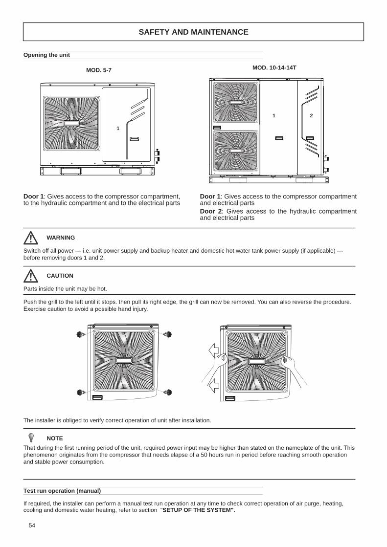
Door 1: Gives access to the compressor compartment and electrical partsDoor 2: Gives access to the hydraulic compartment and electrical parts
Door 1: Gives access to the compressor compartment, to the hydraulic compartment and to the electrical parts
Opening the unit
1 2
1
1 2
1
Switch off all power — i .e . unit power supply and backup heater and domestic hot water tank power supply (if applicable) — before removing doors 1 and 2 .
Push the grill to the left until it stops . then pull its right edge, the grill can now be removed . You can also reverse the procedure . Exercise caution to avoid a possible hand injury.
Parts inside the unit may be hot .
WARNING
CAUTION
SAFETY AND MAINTENANCE
MOD . 10-14-14TMOD . 5-7
The installer is obliged to verify correct operation of unit after installation .
If required, the installer can perform a manual test run operation at any time to check correct operation of air purge, heating, cooling and domestic water heating, refer to section "SETUP OF THE SYSTEM" .
Test run operation (manual)
That during the first running period of the unit, required power input may be higher than stated on the nameplate of the unit. This phenomenon originates from the compressor that needs elapse of a 50 hours run in period before reaching smooth operation and stable power consumption .
NOTE

55
SAFETY AND MAINTENANCE
3 2
1-phase 10~16kW3-phase 12~16kW
1-phase 5/7kW
9.2.3 Main control board of hydraulic module (door2)
20
1
Main control board of hydraulic module
Control box for 5,7KW UNIT Control box for 10~16KW UNIT
main control board of hydraulic module
PCB A PCB B PCB C(at back of the PCB B,only for 3 phase unit)
PCB A PCB B
8
765432
11
9
10
12
13
1423
24
25
26
27
1 Input port for solar energy(CN5)2 Output port for transformer(CN4)3 Power supply port for user interface(CN36)4 Port for remote switch(CN12)5 Port for flow switch(CN8)6 Communicate port between door PCB B and door PCB(CN14)7 Communicate port between door PCB and user interface(CN19)8 Port for temperature sensors(TW_out, TW_in, T1, T2,T2B )(CN6)9 Port for temperature sensor(CN13)10 Port for temperature sensor(T1B, the final outlet temp.)(CN15)11 Digital displays(DIS1)12 Check button(SW4)13 DIP switch(S1,S2) 14 output port for deforst(CN34) 15 Port for anti-freeze eletric heating tape (internal)(CN40)
16 Port for anti-freeze eletric heating tape (internal)(CN41)17 Output port for external heating source / operation output port(CN25)18 Port for anti-freeze eletric heating tape(external) /port for solar energy pump/output port for remote alarm(CN27)19 Port for external circulted pump/pipe pump/mix pump/2-way valve SV2(CN37)20 Port for SV1(3-way valve) and SV3(CN24) 21 Port for internal pump(CN28)22 Input port for transformer(CN20)23 Feedback port for temperature switch(CN1)24 Port for power supply(CN21)25 Feedback port for external temp. switch(shorted in default)(CN2)26 Control port backup heater/booster heater(CN22)27 Control port for room thermostat(CN3)
The image shown here is indicative only. If there is inconsistency between the image and the actual product, the actual product shall govern.
151718 1619202122
The image shown here is indicative only . If there is inconsistency between the image and the actual product, the actual product shall govern .Hydraulic module control board (door2)
Control box for Mod . 5-7 Control box for Mod . 10-14
1-phase Mod . 5-7-10-14 3-phase Mod .14T
1 Input port for solar energy(CN5)2 Output port for transformer(CN4)3 Power supply port for user interface(CN36)4 Port for remote switch(CN12)5 Port for flow switch(CN8)6 Communicate port between door PCB B and door PCB(CN14)7 Communicate port between door PCB and user interface(CN19)8 Port for temperature sensors(TW_out, TW_in, T1, T2,T2B )(CN6)9 Port for temperature sensor(CN13)10 Port for temperature sensor(T1B, the final outlet temp.)(CN15)11 Digital displays(DIS1)12 Check button(SW4)13 DIP switch(S1,S2)14 output port for deforst(CN34)
15 Port for anti-freeze eletric heating tape (internal)(CN40)16 Port for anti-freeze eletric heating tape (internal)(CN41)17 Output port for external heating source / operation output port(CN25)18 Port for anti-freeze eletric heating tape(external) /port for solarenergy pump/output port for remote alarm(CN27)19 Port for external circulted pump/pipe pump/mix pump/2-wayvalve SV2(CN37)20 Port for SV1(3-way valve) and SV3(CN24)21 Port for internal pump(CN28)22 Input port for transformer(CN20)23 Feedback port for temperature switch(CN1)24 Port for power supply(CN21)25 Feedback port for external temp . switch(shorted in default)(CN2)26 Control port backup heater/booster heater(CN22)27 Control port for room thermostat(CN3)

56
SAFETY AND MAINTENANCE
24
PCB A, Inverter board for 1 phase 5,7kw unit. 1
4567
38
9
10
11
2
1-phase 5/7kW
1 To main board (CN101,CN105)2 Compressor connection port U V W (U,V,W)3 Input port N for IPM module(N)4 Input port P for IPM module(P)5 Input port for PFC inductance P1(P1)6 Input port for bridge Rectifiers(P5)7 Input port for Bridge Rectifiers(P6) 8 Output port P of PFC(P2)9 Input port for PFC inductance 3(P3)10 Output port N of PFC(P4)11 +18V(P9)
PCB A, Inverter board for 1-phase Mod . 5-7
1 To main board (CN101,CN105)2 Compressor connection port U V W (U,V,W)3 Input port N for IPM module(N)4 Input port P for IPM module(P)5 Input port for PFC inductance P1(P1)6 Input port for bridge Rectifiers(P5)7 Input port for Bridge Rectifiers(P6)8 Output port P of PFC(P2)9 Input port for PFC inductance 3(P3)10 Output port N of PFC(P4)11 +18V(P9)
25
1 Rectifier bridge input port L
2 Hydraulic compartment input port2
3 Rectifier bridge input port N
4 Power supply N
5 Power supply L
6 Transformer output port
7 BLACK: T3 temperature sensor port
WHITE:T4 temperature sensor port
8 TP temperature sensor port
9 YELLOW: High pressure switch
RED: Low pressure switch
10 Th temperature sensor port
11 Pressure sensor port
12 Wire controller port
13 P/N/+18V port
14 To IPDU/PFC
15 DC fan port
16 Compression electromechanical
heating belt
17 4-way valve port
18 Transformer input port
1-phase 5/7kW
PCB B, Main control board for 1 phase 5,7kw unit.
PCB A
2
4
567891011
12
13
15
14
16
17
183
1

57
24
PCB A, Inverter board for 1 phase 5,7kw unit. 1
4567
38
9
10
11
2
1-phase 5/7kW
1 To main board (CN101,CN105)2 Compressor connection port U V W (U,V,W)3 Input port N for IPM module(N)4 Input port P for IPM module(P)5 Input port for PFC inductance P1(P1)6 Input port for bridge Rectifiers(P5)7 Input port for Bridge Rectifiers(P6) 8 Output port P of PFC(P2)9 Input port for PFC inductance 3(P3)10 Output port N of PFC(P4)11 +18V(P9)
25
1 Rectifier bridge input port L
2 Hydraulic compartment input port2
3 Rectifier bridge input port N
4 Power supply N
5 Power supply L
6 Transformer output port
7 BLACK: T3 temperature sensor port
WHITE:T4 temperature sensor port
8 TP temperature sensor port
9 YELLOW: High pressure switch
RED: Low pressure switch
10 Th temperature sensor port
11 Pressure sensor port
12 Wire controller port
13 P/N/+18V port
14 To IPDU/PFC
15 DC fan port
16 Compression electromechanical
heating belt
17 4-way valve port
18 Transformer input port
1-phase 5/7kW
PCB B, Main control board for 1 phase 5,7kw unit.
PCB A
2
4
567891011
12
13
15
14
16
17
183
1
PCB B, Main control board for 1-phase Mod . 5-7
1 Rectifier bridge input port L2 Hydraulic compartment input port23 Rectifier bridge input port N4 Power supply N5 Power supply L6 Transformer output port7 BLACK: T3 temperature sensor portWHITE:T4 temperature sensor port8 TP temperature sensor port9 YELLOW: High pressure switchRED: Low pressure switch
10 Th temperature sensor port11 Pressure sensor port12 Wire controller port13 P/N/+18V port14 To IPDU/PFC15 DC fan port16 Compression electromechanicalheating belt17 4-way valve port18 Transformer input port
SAFETY AND MAINTENANCE

58
21
9.2.4 PCB for refrigerant system
1 Reserved(CN2)2 Input Port N For Ipm Module(N)
4 Power Supply Of V Phase For Compressor(V)
3 Power Supply Of W Phase ForCompressor(W)
5 Power Supply Of U Phase For Compressor(U)6 Output Port N Of Pfc Module(N_1)7 Output Port P Of Pfc Module(P_1)8 Input Port For Pfc Inductance L_1(L_1)9 Input Port For Pfc Inductance L_2(L_2)
1 Port For Pressure Switch(CN12)2 Port For Suction Temperature Sensor(CN24)3 Port For Pressure Sensor(CN28)4 Port For Discharge Temperature Sensor(CN8)5 Port For Ambient Temperature And Condenser Outlet Temperature Sensor(CN9)6 Port For Communication Between
Outdoor Unit And Bydro-box(CN10)
7 Reserved(CN30)8 Port For Electrical Expansion Value(CN22)9 Input Port For Live Wire(CN1)10 Input Port For Neutral Wire(CN2)11 Output Port For Neutral Wire(CN3)12 Ourput Port For Live Wire(CN4)13 Reserved(CN7)14 Port For 4-way Value(CN13)15 Port For Eletric Heating Tape(CN14)16 Input Port For Transformer(CN26)
10
20
19
18
25
17
16
23
2221
11 13
9
8
7
6
1
9 10
234510 Input Port N For Pfc Module(VIN-N)11 Input Port P Foripm Modele(P)12 Communicate Port Between Pcb A And Pcb B(CN1)13 +15V(CN6)
PCB A, Inverter module for 1-phase 10~16kW unit
15 2614 13 12
17 Power Supply Port For Fan(CN18)18 Port For Down Fan(CN19) 19 Port For Up Fan(CN17) 20 Output Port For Transformer(CN51)21 Check Button(SW2)22 Refrigerant Recovery Button23 Digital Displays(DIS1)24 Ground Wire(CN11)25 Comunication Port For PCBA(CN6)26 Power supply port for hydro-box control board(CN16)
12
1 2 3 4 5 6 7 8PCB B, Main control board for 1-phase 10~16kW unit
24
11
PCB for refrigerant system
PCB A, Inverter module for 1-phase Mod . 10-14
PCB B, Main control board for 1-phase Mod . 10-14
1 Reserved(CN2)2 Input Port N For Ipm Module(N)4 Power Supply Of V Phase For Compressor(V)3 Power Supply Of W Phase ForCompressor(W)
5 Power Supply Of U Phase For Compressor(U)6 Output Port N Of Pfc Module(N_1)7 Output Port P Of Pfc Module(P_1)8 Input Port For Pfc Inductance L_1(L_1)9 Input Port For Pfc Inductance L_2(L_2)
10 Input Port N For Pfc Module(VIN-N)11 Input Port P Foripm Modele(P)12 Communicate Port Between Pcb AAnd Pcb B(CN1)13 +15V(CN6)
1 Port For Pressure Switch(CN12)2 Port For Suction Temperature Sensor(CN24)3 Port For Pressure Sensor(CN28)4 Port For Discharge TemperatureSensor(CN8)5 Port For Outdoor air Temperature AndCondenser Outlet TemperatureSensor(CN9)6 Port For Communication BetweenOutdoor Unit And Bydro-box(CN10)7 Reserved(CN30)
8 Port For Electrical Expansion Value(CN22)9 Input Port For Live Wire(CN1)10 Input Port For Neutral Wire(CN2)11 Output Port For Neutral Wire(CN3)12 Ourput Port For Live Wire(CN4)13 Reserved(CN7)14 Port For 4-way Value(CN13)15 Port For Eletric Heating Tape(CN14)16 Input Port For Transformer(CN26)17 Power Supply Port For Fan(CN18)18 Port For Down Fan(CN19)
19 Port For Up Fan(CN17)20 Output Port For Transformer(CN51)21 Check Button(SW2)22 Refrigerant Recovery Button23 Digital Displays(DIS1)24 Ground Wire(CN11)25 Comunication Port For PCBA(CN6)26 Power supply port for hydro-boxcontrol board(CN16)
21
9.2.4 PCB for refrigerant system
1 Reserved(CN2)2 Input Port N For Ipm Module(N)
4 Power Supply Of V Phase For Compressor(V)
3 Power Supply Of W Phase ForCompressor(W)
5 Power Supply Of U Phase For Compressor(U)6 Output Port N Of Pfc Module(N_1)7 Output Port P Of Pfc Module(P_1)8 Input Port For Pfc Inductance L_1(L_1)9 Input Port For Pfc Inductance L_2(L_2)
1 Port For Pressure Switch(CN12)2 Port For Suction Temperature Sensor(CN24)3 Port For Pressure Sensor(CN28)4 Port For Discharge Temperature Sensor(CN8)5 Port For Ambient Temperature And Condenser Outlet Temperature Sensor(CN9)6 Port For Communication Between
Outdoor Unit And Bydro-box(CN10)
7 Reserved(CN30)8 Port For Electrical Expansion Value(CN22)9 Input Port For Live Wire(CN1)10 Input Port For Neutral Wire(CN2)11 Output Port For Neutral Wire(CN3)12 Ourput Port For Live Wire(CN4)13 Reserved(CN7)14 Port For 4-way Value(CN13)15 Port For Eletric Heating Tape(CN14)16 Input Port For Transformer(CN26)
10
20
19
18
25
17
16
23
2221
11 13
9
8
7
6
1
9 10
234510 Input Port N For Pfc Module(VIN-N)11 Input Port P Foripm Modele(P)12 Communicate Port Between Pcb A And Pcb B(CN1)13 +15V(CN6)
PCB A, Inverter module for 1-phase 10~16kW unit
15 2614 13 12
17 Power Supply Port For Fan(CN18)18 Port For Down Fan(CN19) 19 Port For Up Fan(CN17) 20 Output Port For Transformer(CN51)21 Check Button(SW2)22 Refrigerant Recovery Button23 Digital Displays(DIS1)24 Ground Wire(CN11)25 Comunication Port For PCBA(CN6)26 Power supply port for hydro-box control board(CN16)
12
1 2 3 4 5 6 7 8PCB B, Main control board for 1-phase 10~16kW unit
24
11
SAFETY AND MAINTENANCE

59
22
1. +15V port(CN4)2. To MCU(CN1)3. IPM input N4. Compressor connection port W5. Compressor connection port V6. Compressor connection port U7. IPM input P8. Power for switching power supply(CN2)
10
11
1 Power supply for the main PCB(CN250) 2 Port for pressure sensor(CN36)3 Port for sunction temperature sensor(CN4)4 Port for discharge temperature sensor(CN8)5.1 Port for outdoor temperature sensor(CN9)5.2 Port for condenser outlet temperature sensor(CN9)6.1 Port for high pressure switch(CN6)6.2 Port for low pressure switch(CN6)
10 Port for electrical expansion value(CN22)11 Port for power supply(CN41)12 Power supply for hydro-box control board(CN6)13 PFC control port(CN63)14 Reserved(CN64)15 Port for 4-way value(CN65)16 Port for eletric heating tape(CN66)17 PTC control(CN67)
18 Reserved(CN68)19 Port for down fan(CN19)20 Port for up fan(CN17)21 Power supply port for module(CN70\71)22 Communication port for IPDU(CN201)23 Port for voltage check(CN205)24 Refrigerant recovery button(SW1)25 Check button(SW2)
1
2
34567
8
1 24 225 3 4 5.15.2 6.1 6.27
13 1214151617181921 202223
PCB B, Main control board for 3-phase 12~16kW unit
PCB A, Inverter module for 3-phase 12~16kW unit
PCB A, Inverter module for 3-phase Mod . 14T
22
1. +15V port(CN4)2. To MCU(CN1)3. IPM input N4. Compressor connection port W5. Compressor connection port V6. Compressor connection port U7. IPM input P8. Power for switching power supply(CN2)
10
11
1 Power supply for the main PCB(CN250) 2 Port for pressure sensor(CN36)3 Port for sunction temperature sensor(CN4)4 Port for discharge temperature sensor(CN8)5.1 Port for outdoor temperature sensor(CN9)5.2 Port for condenser outlet temperature sensor(CN9)6.1 Port for high pressure switch(CN6)6.2 Port for low pressure switch(CN6)
10 Port for electrical expansion value(CN22)11 Port for power supply(CN41)12 Power supply for hydro-box control board(CN6)13 PFC control port(CN63)14 Reserved(CN64)15 Port for 4-way value(CN65)16 Port for eletric heating tape(CN66)17 PTC control(CN67)
18 Reserved(CN68)19 Port for down fan(CN19)20 Port for up fan(CN17)21 Power supply port for module(CN70\71)22 Communication port for IPDU(CN201)23 Port for voltage check(CN205)24 Refrigerant recovery button(SW1)25 Check button(SW2)
1
2
34567
8
1 24 225 3 4 5.15.2 6.1 6.27
13 1214151617181921 202223
PCB B, Main control board for 3-phase 12~16kW unit
PCB A, Inverter module for 3-phase 12~16kW unit
PCB B, Main control board for 3-phase Mod . 14T
1 Power supply for the main PCB(CN250)2 Port for pressure sensor(CN36)3 Port for sunction temperature sensor(CN4)4 Port for discharge temperature sensor(CN8)5 .1 Port for outdoor temperature sensor(CN9)5 .2 Port for condenser outlet temperature sensor(CN9)6 .1 Port for high pressure switch(CN6)6 .2 Port for low pressure switch(CN6)10 Port for electrical expansion value(CN22)11 Port for power supply(CN41)12 Power supply for hydro-boxcontrol board(CN6)13 PFC control port(CN63)
14 Reserved(CN64)15 Port for 4-way value(CN65)16 Port for eletric heating tape(CN66)17 PTC control(CN67)18 Reserved(CN68)19 Port for down fan(CN19)20 Port for up fan(CN17)21 Power supply port for module(CN70\71)22 Communication port for IPDU(CN201)23 Port for voltage check(CN205)24 Refrigerant recovery button(SW1)25 Check button(SW2)
SAFETY AND MAINTENANCE
1 . +15V port(CN4)2 . To MCU(CN1)3 . IPM input N4 . Compressor connection port W5 . Compressor connection port V6 . Compressor connection port U7 . IPM input P8 . Power for switching power supply(CN2)

60
SAFETY AND MAINTENANCE
23
PCB C, filter board for 3 phase 12~16kw unit.
3-phase 12~16kW
1
2
3
4567
11
10
9
8
1 Power supply L3(L3)2 Power supply L2(L2)3 Power supply L1(L1)4 Power supply N(N)5 Ground wire(GND_1)6 Power supply for load(CN18)7 Power supply for main control board(CN19)8 Power filtering L1(L1’)9 Power filtering L2(L2’)10 Power filtering L3(L3’)11 Ground wire(GND_2)
PCB C, filter board for 3-phase Mod. 14T
1 Power supply L3(L3)2 Power supply L2(L2)3 Power supply L1(L1)4 Power supply N(N)
5 Ground wire(GND_1)6 Power supply for load(CN18)7 Power supply for main control board(CN19)8 Power filtering L1(L1’)
9 Power filtering L2(L2’)10 Power filtering L3(L3’)11 Ground wire(GND_2)
Parameters check in the unit
To check the parameters of hydraulic box, open door 2 and you’ll see the PCB like following, the digital display will show the tem-perature of outlet water in normal condition (‘0’ will display if the unit is off or error code will display if error occurs) . Long press the check button and the digital display will show the operating mode . Then press the check button in sequence . The digital di-splay will show the value, the implication of the value illustrated in the diagram below:
hydraulic box SW4
check button
4NC
02NC
21NC
91NC
8NC
SF
41NC
63NC
CN21
72NC
42NC
43NC
31NC6NC
1S 2S
3NC
4WSYREUQ
82NC
73NC
52NC
04NC
14NC
5NC
51NC
CN122NC 2NC
DRAOBLORTNOCXOB-ORDYH
Number Implication
0 Temperature of outlet water when unit is on, when the unit is off, ‘0’ will display
1 Operation mode(0——OFF, 2——COOL, 3——HEAT, 5——Water heating)
2 Capacity requirement before correction3 Capacity requirement after correction4 Outlet water temperature of backup heater
5 Outlet water temperature of additional heating source
6 Target outlet water temperature calculated from climate-related curves
7 Room temperature8 Temperature of domestic hot water
9 Temperature of refrigerant at outlet /inlet of plate heat exchanger when in heat mode/cool mode
10 Temperature of refrigerant at inlet /outlet of plate heat exchanger when in heat mode/cool mode
11 Temperature of water at outlet of plate heat exchanger
12 Temperature of water at inlet of plate heat exchanger
13 Outdoor air temperature14 Current of backup heater 115 Current of backup heater 2
16 Error/protection code for the last time,”—” will display if no error/protection occur
17 Error/protection code for the second last time, ”—” will display if no error/protection occur
18 Error/protection code for the third last time, ”—” will display if no error/protection occur
19 Version of software (hydraulic module)

61
SAFETY AND MAINTENANCE
To check the parameters on the re-
frigerant side, open door 1 and you’ll
see the PCB like the following (diffe-
rent for 1-phase and 3-phase unit):
the digital display will show the pre-
sent compressor frequency (‘0’ will di-
splay if the unit is off or error code will
display if error occurs) . Long press
the check button and the digital di-
splay will show the operating mode,
and then press the check button in
sequence . The digital display will
show the value, the implication of the
value is shown in the diagram below:
Number Implication
0 Frequency of compressor at present
1 Operation mode (0——Standby, 2——COOL, 3——HEAT, 5——refrigerant recovery)
2 Fan speed3 Frequency from hydraulic module4 Frequency after restriction by the outdoor unit
5 Temperature of tube at outlet/inlet of condenser when in cool/heat mode
6 Outdoor air temperature7 Discharge temperature
Number Implication
1TC
4NC
3NC
1NC
2NC
8NC
03NC01NC
11NC
9NC
21NC
TUOSNART
62NC6NCNISNART 15NC
81NC
22NC
TUO_L
TUO_N
NI_L
NI_N
WS 4
O N
1 2 3WS 3
O N
1 2 3
ECROFLOOCKCEHC
WS 1WS 2 D IS 1
71NC91NC
DRAOBLORTNOCNIAM31NC
41NC42NC
82NC
61NC
SW2
SW2
check button
check button
check button
SW2
56NC
46NC
76NC
66NC
86NC
71NC
102CI
502NC
91NC
11NC
6NC
8NC
9NC
01NC
22NC
102NC
DRAOBLORTNOCNIAM
052NC
2WS1WS
1 2 3
O N
1 2
O N
7WS 8WS
36NC
4NC
63NC
etoNnoitceridgnidaerhT
)14NC(16NC
)16NC(14NC
11NC01NC
LN
PEPE
PE
L1
8 Suction temperature (when the temperature lower than -9°C” .” Will stand for negative sign)
9 The opening of EEV (the value display multiply 8 will be the actual opening)
10 Actual current11 Actual voltage
12 Pressure of refrigerant (evaporate/condense pres-sure when in cool /heat mode )
13 Version of software (outdoor unit)
14 Error/protection code for the last time, “nn”will display if no error/protection occurs
15 --

62
This section provides useful information for diagnosing and correcting certain troubles which may occur in the unit .This troubleshooting and related corrective actions may only be carried out by your local technician .
Before starting the troubleshooting procedure, carry out a thorough visual inspection of the unit and look for obvious defects such as loose connections or defective wiring .
General guidelines
Possible malfunctioning
When carrying out an inspection on the switch box of the unit, always make sure that the main switch of the unit is switched off .
When a safety device was activated, stop the unit and find out why the safety device was activated before resetting it. Under no circumstances can safety devices be bridged or changed to a value other than the factory setting . If the cause of the problem cannot be found, call your local dealer .If the pressure relief valve is not working correctly and is to be replaced, always reconnect the flexible hose attached to the pres-sure relief valve to avoid water dripping out of the unit!
WARNING
For problems related to the optional solar kit for domestic water heating, refer to the troubleshooting in the Installation & Owner's manual for that kit .
The unit is turned on but the unit is not heating or cooling as expected
NOTE
POSSIBLE CAUSES CORRECTIVE ACTIONThe temperature setting is not correct .
Check the controller set point .T4HMAX, T4HMIN in heat mode .T4CMAX,T4CMIN in cool mode .T4DHWMAX,T4DHWMIN in DHW mode .
The water flow is too low .
• Check that all shut off valves of the water circuit are completely open .• Check if the water filter needs cleaning .• Make sure there is no air in the system (purge air) .• Check on the manometer that there is sufficient water pressure . The water pressure must be>1 bar (water is cold) .• Make sure that the expansion vessel is not broken .• Check that the resistance in the water circuit is not too high for the pump
The water volume in the installation is too low .
Make sure that the water volume in the installation is above the minimum required value (refer to "9 .3 water pipework/Checking the water volume and expansion vessel pre-pressure") .
SAFETY AND MAINTENANCE

63
Pump is making noise (cavitation)
The water pressure relief valve opens
The water pressure relief valve leaks
Space heating capacity shortage at low outdoor temperatures
POSSIBLE CAUSES CORRECTIVE ACTIONThere is air in the system .
Purge air .
Water pressure at pump inlet is too low .
• Check on the manometer that there is sufficient water pressure . The water pressure must be > 1 bar (water is cold) .• Check that the manometer is not broken .• Check that the expansion vessel is not broken .• Check that the setting of the pre- pressure of the expansion vessel is correct (refer to "9 .3 water pipework/Checking the water volume and expansion vessel pre-pressure") .
POSSIBLE CAUSES CORRECTIVE ACTIONThe expansion vessel is broken .
Replace the expansion vessel .
The filling water pressure in the installation is higher than 0 .3MPa .
Make sure that the filling water pressure in the installation is about 0 .15~0 .20MPa (refer to "9 .3 water pipework/Checking the water volume and expansion vessel pre-pressure") .
POSSIBLE CAUSES CORRECTIVE ACTIONDirt is blocking the water pressure relief valve outlet .
Check for correct operation of the pressure relief valve by turning the red knob on the valve counter clockWise:• If you do not hear a clacking sound, contact your local dealer .• In case the water keeps running out of the unit, close both the water inlet and outlet shut-off valves first and then contact your local dealer .
POSSIBLE CAUSES CORRECTIVE ACTIONBackup heater opera-tion is not activated .
Check that the "OTHER HEATING SOURCE/ BACKUP HEATER"is enabled, see "10 .7 Field settings" Check whether or not the thermal protector of the backup heater has been activated (refer to 9 .2 .3 Switch box main components (door 2), "Backup heater thermal protector" for location of the reset button) .Check if booster heater is running, the backup heater and booster heater can’t operate simulta-neously .
Too much heat pump capacity is used for heating domestic hot water (applies only to installations with a domestic hot water tank) .
Check that the 't_DHWHP_MAX' and “t_ DHWHP_RESTRICT” are configured appropriately:• Make sure that the 'DHW PRIORITY' in the user interface is disabled .• Enable the”T4_TBH_ON “in the user interface/FOR SERVICEMAN to activate the booster heater for domestic water heating .
SAFETY AND MAINTENANCE

64
In order to ensure optimal availability of the unit, a number of checks and inspections on the unit and the field wiring have to be carried out at regular intervals .This maintenance needs to be carried out by your local technician . In order to ensure optimal availability of the unit, a number of checks and inspections on the unit and the field wiring have to be carried out at regular intervals.This maintenance has to be carried out by your local Midea technician .
The described checks must be executed at least once a year by qualified personnel.1 . Water pressureCheck if the water pressure is above 1 bar . If necessary add water .2. Water filterClean the water filter.3 . Water pressure relief valve Check for correct operation of the pressure relief valve by turning the black knob on the valve counter-clockWise:■ If you do not hear a clacking sound, contact your local dealer.■ In case the water keeps running out of the unit, close both the water inlet and outlet shut-off valves first and then contact your local dealer .4 . Pressure relief valve hoseCheck that the pressure relief valve hose is positioned appropriately to drain the water .5 . Backup heater vessel insulation coverCheck that the backup heater insulation cover is fastened tightly around the backup heater vessel .6. Domestic hot water tank pressure relief valve (field supply) Applies only to installations with a domestic hot water tank . Check for correct operation of the pressure relief valve on the domestic hot water tank .7 . Domestic hot water tank booster heaterApplies only to installations with a domestic hot water tank . It is advisable to remove lime buildup on the booster heater to extend its life span, especially in regions with hard water . To do so, drain the domestic hot water tank, remove the booster heater from the domestic hot water tank and immerse in a bucket (or similar) with lime-removing product for 24 hours .8 . Unit switch box■ Carry out a thorough visual inspection of the switch box and look for obvious defects such as loose connections or defective wiring .■ Check for correct operation of contactors with an ohm meter. All contacts of these contactors must be in open position.9 . Use of glycol(Refer also to section "HYDRAULIC CONNECTIONS" ) Document the glycol concentration and the pH-value in the system at least once a year .■ A PH-value below 8.0 indicates that a significant portion of the inhibitor has been depleted and that more inhibitor needs to be added .■ When the PH-value is below 7.0 then oxidation of the glycol occurred, the system should be drained and flushed thoroughly before severe damage occurs . Make sure that the disposal of the glycol solution is done in accordance with relevant local laws and regulations .
ELECTRIC SHOCK ■ Before carrying out any maintenance or repair activity, always switch off the circuit breaker on the supply panel, remove the fuses (or switch off the circuit breakers) or open protection devices of the unit .■ Make sure that before starting any maintenance or repair activity that the power supply to the outdoor unit is switched off.■ Do not touch live parts for 10 minutes after the power supply is turned off because of high voltage risk.■ The heater for the compressor may operate even in stop mode.■ Please note that some sections of the electric component box are hot.■ Make sure you do not touch a conductive section.■ Do not rinse the unit. This may cause electric shocks or fire.■ When service panels are removed, live parts can be easily touched by accident. Never leave the unit unattended during installation or servicing when service panel is removed .
DANGER
SAFETY AND MAINTENANCE

65
SAFETY AND MAINTENANCE
Part in question Residue hazard Mode Precautions
Compressor and delivery pipe Burns Contact with the pipes and/or com-
pressorAvoid contact by wearing
protective gloves
Delivery pipes, heat recoveryexchanger and coils Explosion Excessive pressure
Turn off the machine,check the high pressure switch
and safety valve,the fans and condenser
Pipes in general Ice burns Leaking refrigerant Do not pull on the pipes
Electrical cables, metal parts Electrocution, serious burns Defective cable insulation, live metal parts
Adequate electrical protection (cor-rectly ground the unit)
Heat exchange coils Cuts Contact Wear protective gloves
Fans Cuts Contact with the skin Do not push the hands or objects through the fan grille
SAFETY AND MAINTENANCE
Basic safety rules
Recall that the use of products that use electricity and water entails the observance of some basic safety rules , such as: This applian-ce is not intended for use by persons ( including children) with reduced physical , sensory or mental capabilities or lack of experience and knowledge, unless supervised or instructed on the use of the appliance by a person responsible for their safety . Children should be supervised to ensure that they do not play with the appliance .
It is forbidden to any technical intervention or maintenance without first disconnecting the unit from the mains supply by moving the master switch and the main control panel to “Off” .You may not modify safety equipment or settings .Do not pull, detach or twist the electrical cables coming from the unit even if it is disconnected from the mains supply .It is forbidden to leave containers of flammable substances near the unit .Do not touch the appliance when barefoot or with wet or damp parts of the body .It is forbidden to open the doors of access to the internal parts of the unit without first ensuring that the system switch to “Off” .Not dispose of, abandon or leave within reach of children packaging materials as it can be a potential source of danger .
IMPORTANT SAFETY INFORMATION There is no guarantee proper operation as a result of a fire, before restarting the machine, contact an authorized service center . If equipped with safety valves refrigerant, in case of excessive pressure the safety valves can discharge high temperature refrigerant gas to the atmosphere . Wind, earthquakes and other natural phenomena of exceptional intensity were not considered . When using the unit in an aggressive atmosphere and or with aggressive water consult the factory .
Residual Risks
The machine has been designed with a view to reducing the risks to persons and the environment in which it is installed, to the minimum . To eliminate residual risks, it is therefore advisable to become as familiar as possible with the machine in order to avoid accidents that could cause injuries to persons and/or damage to property.a . Access to the unitOnly qualified persons who are familiar with this type of machine and who are equipped with the necessary safety protections (fo-otwear, gloves, helmet, etc .) may be allowed to access the machine . Moreover, in order to operate, these persons must have been authorized by the owner of the machine and be recognized by the actual Manufacturer .b . Elements of riskThe machine has been designed and built so as not to create any condition of risk . However, residual risks are impossible to eliminate during the designing phase and are therefore listed in the following table along with the instructions about how to neutralize them .
Disconnection and disposal
The machine contains lubricating oil and refrigerant gas for which, during the destruction of the unit, these fluids will be recovered and disposed of in accordance with the rules in force in the country where it is installed . During the disconnection thus avoid spills or leaks of refrigerant gas and of the plant water if treated with additives or antifreeze substances . The machine must not be abandoned in the process of destruction, but it can also be stored outdoors with gas, water and electrical circuits intact and closed . For dismissing and disposal, deliver the units to specialized centres according to your national laws .
Basic safety rules
Recall that the use of products that use electricity and water entails the observance of some basic safety rules , such as: This applian-ce is not intended for use by persons ( including children) with reduced physical , sensory or mental capabilities or lack of experience and knowledge, unless supervised or instructed on the use of the appliance by a person responsible for their safety . Children should be supervised to ensure that they do not play with the appliance .
It is forbidden to any technical intervention or maintenance without first disconnecting the unit from the mains power supply by can to “Off” .You may not modify safety equipment or settings .Do not pull, detach or twist the electrical cables coming from the unit even if it is disconnected from the mains supply .It is forbidden to leave containers of flammable substances near the unit .Do not touch the appliance when barefoot or with wet or damp parts of the body .It is forbidden to open the doors of access to the internal parts of the unit without first ensuring that the system switch to “Off” .Not dispose of, abandon or leave within reach of children packaging materials as it can be a potential source of danger .
IMPORTANT SAFETY INFORMATION There is no guarantee proper operation as a result of a fire, before restarting the machine, contact an authorized service center . If equipped with safety valves refrigerant, in case of excessive pressure the safety valves can discharge high temperature refrigerant gas to the atmosphere . Wind, earthquakes and other natural phenomena of exceptional intensity were not considered . When using the unit in an aggressive atmosphere and or with aggressive water consult the factory .

66
SAFETY AND MAINTENANCE
General recommendations about the R410A refrigerant used
1 SUPPLIER COMPANY AND PRODUCT IDENTIFICATIONCard No . FRIG 8Product R-410ASupplier company identification RIVOIRA SpA2 COMPOSITION / INFORMATION ON INGREDIENTSSubstance / Preparation PreparationComponents / Impurities Contains the following components : Difluoromethane (R32) 50 % in weight Pentafluoroethane (R125) 50 % in weightEEC No . Non-applicable for mixturesTrade-name / /3 IDENTIFICATION OF HAZARDSIdentification of hazards Liquefied gas . The vapours are heavier than air and can cause suffocation, reducing the oxygen available for bre-
athing . Rapid evaporation of the fluid can cause freezing . Can cause cardiac arrhythmia .4 FIRST-AID MEASURESInhalation Do not administer anything if the person has fainted . Take the person outdoors . Use oxygen or artificial respiration if necessary . Do not administer adrenaline or similar substances .Contact with eyes Rinse thoroughly with plenty of water for at least 15 minutes and see a doctor .Contact with skin Wash immediately with plenty of water . Immediately remove all contaminated garments .Swallowing5 FIRE-PREVENTION MEASURESSpecific hazards Increase in pressure .Dangerous fumes Halogen acids, traces of carbonyl halides .Fire-extinguishing means usable All the known fire-extinguishing means can be used .Specific methods Cool the containers/tanks with water sprays .Special protection equipment Use self-contained breathing apparatus in confined spaces .6 MEASURES AGAINST ACCIDENTAL SPILLING OF THE PRODUCTPersonal protection Evacuate personnel to safe areas . Provide for adequate ventilation . Use personal protection
equipmentProtection for the environment It evaporates .Product removal methods It evaporates .7 HANDLING AND STORAGEHandling and storage Ensure an adequate air change and/or extraction in the workplaces . Only use well-ventilated rooms .
Do not breathe vapours or aerosols . Carefully close the containers and keep them in a cool, dry and well-ventilated place . Keep in the original containers .
Incompatible products Explosives, flammable materials, organic peroxides .8 CONTROL OF EXPOSURE / PERSONAL PROTECTIONPersonal protection Ensure adequate ventilation, especially in closed areas .Control parameters Difluoromethane (R32): Recommended exposure limits: AEL (8h and 12h TWA) = 1000 ml/m3 Pentafluoroethane (R125): Recommended exposure limits: AEL (8h and 12h TWA) = 1000 ml/m3Respiratory tract protection For rescue and for maintenance works in tanks, use self-contained breathing apparatus . The vapours
are heavier than air and can cause suffocation, reducing the oxygen available for breathing .Eye protection Total protection glasses .Hand protection Rubber gloves .Hygiene measures Do not smoke .9 CHEMICAL-PHYSICAL PROPERTIESRelative density, gas (air=1) Heavier than air .Solubility in water (mg/l) Not known, but deemed very low .Appearance Colourless liquefied gas .Odour Similar to ether .Fire point Does not ignite .10 STABILITY AND REACTIVITYStability and reactivity No decomposition if used according to the special instructions .Materials to be avoided Alkali metals, alkali-earth metals, granulated metal salts, Al, Zn, Be, etc . in powder .Hazardous products of decomposition Halogen acids, traces of carbonyl halides .11 TOXICOLOGICAL INFORMATIONLocal effects Concentrations substantially above the value TLV (1000 ppm) can cause narcotic effects . Inhalation
of highly concentrated products of decomposition can cause respiratory insufficiency (pulmonary oedema) .
Long-term toxicity No carcinogenic, teratogenic or mutagenic effects have been recorded in experiments on animals .Specific effects Rapid evaporation of the fluid can cause freezing . Can cause cardiac arrhythmia .12 ECOLOGICAL INFORMATIONEffects linked to ecotoxicity Pentafluoroethane (R125) Potential global warming with halocarbides; HGWP (R-11 = 1) = 0 .84 Potential impoverishment of the ozone; ODP (R-11 = 1) = 0
General recommendations about the R410A refrigerant used
SAFETY AND MAINTENANCE
PRODUCT IDENTIFICATION

67
SAFETY AND MAINTENANCE
13 CONSIDERATIONS ON DISPOSALGeneral Do not dispose of where accumulation can be hazardous . Usable with reconditioning . The depressurised containers must be returned to the supplier . Contact the supplier if instructions for use are deemed necessary .14 INFORMATION FOR TRANSPORTDesignation for transport LIQUEFIED GAS N .A .S . ( DIFLUOROMETHANE, PENTAFLUOROETHANE )UN No . 3163Class/Div 2 .2ADR /RID No . 2, 2nd AADR/RID hazard no . 20ADR label Label 2 : non-toxic non-flammable gas .CEFIC Groupcard 20g39 - AOther information for transport Avoid transport on vehicles where the loading zone is not separate from the cab . Make sure the driver is informed about the potential risk of the load and knows what to do in case of accident or emergency . Before starting transport, make sure the load is properly secured and : make sure the valve of the container is closed and does not leak; make sure the blind cap of the valve (when provided) is correctly fitted; make sure the cap (when provided) is correctly fitted and that there is an adequate ventilation passage; ensure compliance with the current provisions .15 INFORMATION ON REGULATIONSThe product must not be labelled according to Directive 1999/45/EC .Comply with the regulations given below, and the relevant applicable updates and amendments .Circulars no . 46/79 and 61/81 of the Ministry of Labour : Risks related to the use of products containing aromatic aminesLeg . Decree no . 133/92 : Regulations on the discharge of hazardous substances in watersLeg . Decree no . 277/91 : Protection of workers against noise, lead and asbestosLaw 256/74, Decree 28/1/92, Leg . Decree no . 52 dated 3/2/97, Decree dated 28/4/97 as amended : Classification, packing and labelling of hazardous substances and preparationsDecree no . 175/88, as amended : Activities with significant accident risks (Seveso Law)Decree no . 203/88 : Emissions into the atmosphereDecree no . 303/56 : Work hygieneDecree no . 547/55 : Regulations on accident preventionLeg . Decree no .152 dated 11/5/99 : Protection of waters16 OTHER INFORMATIONRecommended uses RefrigerantCan cause suffocation in high concentration .Keep in a well-ventilated place .Do not breathe the gas .The risk of suffocation is often underestimated and must be clearly explained during the training of operators .Ensure compliance with all the national and regional regulations .Before using this product in any new process or trial, an in-depth study on safety and compatibility of the product with the materials must be carried out .The above information is based on our current know-how and describes the product according to the safety requirements . It does not however repre-sent a guarantee and assurance of the qualities in a legal sense . Each person responds personally for compliance with such regulations .
First aid
• Move the victim away from the toxic source, keep him warm and allow him to rest .• Administer oxygen if necessary .• Proceed with artificial respiration if necessary .• Give heart massage in the case of heart failure .• Immediately seek medical help . Contact with the skin:• Immediately thaw the affected parts under running lukewarm water .• Remove contaminated clothing (garments may stick to the skin in the case of ice burns) if they have not adhered to the skin .• Seek medical assistance if necessary . Contact with the eyes:• Immediately rinse the eyes with physiologic eyewash or clean water for at least 10 minutes with the eyelids pulled open .• Seek medical assistance if necessary . Swallowing:• Do not make the victim vomit . If the victim is conscious, have him rinse his mouth out with clean water and then drink 200, 300 ml of water .• Immediately seek medical help .• Do not administer adrenaline or sympathomimetic drugs after exposure owing to the risk of cardiac arrhythmia .For further information about the characteristics of the refrigerant, consult the technical briefs that can be obtained from manufactu-rers of refrigerant products .
SAFETY AND MAINTENANCE

68
DESCRIPTION WEEKLY MONTHLY EVERY SIX MONTHSVisual inspection of the unit •
Inspection of hydraulic circuit •Inspection of electrical system •
Inspection of condensing system •Inspection of the water heat exchanger •
Inspection of the water filter •Inspection of the water pumps (if present) •
Reading and adjustment of the operating parameters •
General Rules for Maintanance
The maintenance is extremely important for the functioning of the system and the regular working of the unit over time .In accordance with the European Regulation EC 303/2008 , it should be noted that companies and engineers in maintenance , repair, leak testing and recovery / recycle refrigerant gases should be CERTIFIED in accordance with local regulations .Maintenance must be performed in compliance with the safety rules and tips given in the manual supplied with the unit .Routine maintenance helps maintain unit efficiency, reduce the rate of deterioration which each device is subject in time and gather information and data to understand the efficiency of the unit and prevent failures .For extraordinary maintenance or in case you need service , contact only to a specialized service center approved by the manufac-turer and use original spare parts .In accordance with the European Regulation EC 1516/2007 it is necessary to prepare a “equipment record” .Provide anyway a databook (not supplied) that allows you to keep track of interventions made on the unit; in this way it will be easier to properly program the various interventions and will facilitate a possible troubleshooting .Bring on the databook : date, type of intervention made, description of the intervention , measurements , reported anomalies , alarms recorded in the alarm history , etc . . . .
Routine maintenance
The inspections described below, to which the unit must be subjected, do not require specific technical know-how.They merely include a few simple inspections involving certain parts of the unit .The table below gives a recommended list of inspections which should be carried out at the indicated intervals .Provide controls and interventions more frequently in case of heavy (continuous or intermittent high, close to operating limits, etc . . .) or critical (essential service such as data centres, hospital etc . . .) use .
• Visual inspection of the structure of the unitWhen checking the condition of the parts that form the structure of the unit, pay particular attention to the parts liable to rust .If traces of rust are noted, they must be treated with rust-inhibitor paint in order to eliminate or reduce the problem .Check to make sure that the external panels of the unit are well fixed .Bad fixing gives rise to noise and abnormal vibrations .
• Inspection of hydraulic circuitCheck visually to make sure that there are no leaks in the hydraulic circuit . Check that water filters are clean .
• Inspection of electrical systemMake sure that power cables that supply the unit are not torn, cracked or damaged in a way that could impair its insulation .
• Inspection of the ventilated condensing/evaporating sectionWARNING: The finned pack exchanger has fins made of aluminium or some other thin material, thus even accidental contact could cause cuts .
Condensing/Evaporating coilsIn view of the function of this component, it is very important for the surface of the exchanger to be as free as possible from clogging caused by items that could reduce the fan’s air flow rate and, thus, the performances of the unit itself .The following operations may be required:- Remove all impurities (such as paper scraps, leaves, etc .) that could be clogging the surface of the bank either by hand or using a brush (comply with the above mentioned safety prescriptions) .- If the dirt has deposited on the fins and is difficult to remove by hand, use a flow of compressed air or pressurized water on the aluminium surface of the coils, remembering to direct the flow in a vertical and opposite to the standard flow direction to prevent the fins from being damaged .- “Comb” the coils with the relative tool, using the appropriate comb spacing for the fins if some parts of them are bent or squashed .
SAFETY AND MAINTENANCESAFETY AND MAINTENANCE
General Rules for Maintanance
Routine maintenance

69
CAUTION As a result of extraordinary maintenance on the cooling circuit with component replacement, before restarting the machine, perform the following steps: - Pay attention to restore the refrigerant charge indicated on the name plate of the machine . - Open all the ball valves in the refrigerant circuit . - Correctly connect the power supply and grounding . - Check the hydraulic connections . - Check that the water pump is working properly . - Clean water filters . - Check that the finned coils are not dirty or clogged . - Check the proper rotation of fans .- Check correct operation of safety devices with particular attention to differential water pressure switch and / or water fl ow switch.
Axial fansVisually inspect these parts to make sure that the fans are well fixed to the bearing grille and that this latter is fixed to the structure of the unit . Check the fan bearings, and close the terminal box and cable glands . Bearings damaged and bad fixing are the source of abnormal noise and vibrations,
• Inspection of the water heat exchangersThe exchangers must ensure the maximum heat transfer possible so keep them clean and free from dirt that may reduce efficiency; make sure that the temperature difference between water outlet temperature and evaporation/condensation does not increase over time, if the difference exceeds 8 -10 ° C it is necessary to proceed cleaning the water side of the exchanger, keeping in mind the following: water circulation must be in the opposite direction than normal, the fluid velocity does not exceed 1 .5 times the nominal velocity and use just water or moderately acid products but only water for final washing.
• Inspection of the water filtersMake sure to clean the filter and remove any impurities that block the proper flow of water, contributing to increase pressure drop and therefore energy consumption of the pumps . Refer to the section “Hydraulic Connections” too .
• Inspection of the water pumpsCheck water leakages, the state of the bearings, the closing of the terminal box and integrity of the cable . Bearings damaged and bad fixing are the source of abnormal noise and vibrations,
• Reading and adjustment of the operating parametersThis control can be done using the pressure gauges (if installed) of the refrigerant circuits and using the pressure and temperature gauges (if installed) of the hydraulic circuits of the unit (evaporator + heat recovery - if present)
NOTE:FOR THE PLANT WATER FILL AND DRAIN REFER TO THE SECTION HYDRAULIC CONNECTIONS
SAFETY AND MAINTENANCESAFETY AND MAINTENANCE

70
ERP DATA
55
unit 5 7
[dB(A)] / / / / / / / / /
[dB(A)] 61 65 66 67 71 71 68 71 71
Capacity of theback-up heaterintegrated inthe unit
Psup back-up heater [kW] 0 0 0 0 0 0 0 0 0
Y/N No No No No No No No No No
Space heatingEnergy efficiencyclass 35°C (Lowtemp. app.)
- A++ A++ A++ A++ A++ A++ A++
Space heatingEnergy efficiencyclass 55°C (Mediumtemp. app.)
- A++ A++ A++ A++ A++ A++ A++
Prated (declaredheating capacity) @ –10°C
[kW] 10 12 14 16 12 14 16
Seasonal spaceheating efficiency (ηs)
[%] 162 166 173 167 175 168 164
Annual energyconsumption
[kWh] 4,896 6,312 6,630 7,957 5,544 6,551 8,002
Prated (declaredheating capacity) @ –10°C
[kW] 11 11 13 14 11 13 14
Seasonal spaceheating efficiency (ηs)
[%] 129 129 129 125 131 128 126
Annual energyconsumption
[kWh] 7,025 7,025 8,550 8,973 6,757 8,291 9,172
(A) condition (-7°C)
Pdh (declared heatingcapacity)
[kW] 9.1 11.4 12.8 13.5 10.6 12.0 12.0
COPd (declaredCOP)
- 2.74 2.92 2.78 2.78 2.83 2.66 2.65
Cdh(degradationcoefficient)
- 0.90 0.90 0.900.90 0.90 0.90 0.90
Pdh (declared heatingcapacity)
[kW] 5.3 6.7 7.8 9.0 6.6 7.2 8.6
COPd (declaredCOP)
- 4.10 4.25 4.09 3.99 4.08 3.97 3.97
Cdh(degradationcoefficient)
- 0.90 0.90 0.90 0.90 0.90 0.90 0.90
Pdh (declared heatingcapacity)
[kW] 3.5 4.4 4.8 6.1 4.4 4.9 5.6
COPd (declaredCOP)
- 5.90 6.42 6.12 6.12 6.22 6.36 6.03
Cdh(degradationcoefficient)
- 0.90 0.90 0.90 0.90 0.90 0.90 0.90
Pdh (declared heatingcapacity)
[kW] 1.4 2.0 3.1 3.1 3.7 3.8 4.0
COPd (declaredCOP)
- 4.40 6.48 8.83 7.84 9.37 9.00 8.54
Cdh(degradationcoefficient)
- 0.90 0.90 0.90 0.90 0.90 0.90 0.90
Average climate (Design temperature = –10°C)
Product fiche 1
Heat pump space heater
Indoor unit sound power (*)
Outdoor unit sound power (*)
off peak operation function integratedin Heat pump
Space heating35°C
Space heating55°C
Part load conditions space heating average climate low temperature application
(B) condition(2°C)
(C) condition(7°C)
(D) condition(12°C)
A++ A++
A++ A++
5 7
176 178
2,143 2,989
7 7
126 126
4,228 4,228
4.1 5.80
2.85 2.80
0.90 0.90
2.4 3.6
4.53 4.18
0.90 0.90
1.7 2.3
6.08 6.39
0.90 0.90
1.3 1.4
8.92 9.24
0.90 0.90
/
68
0
No
A++
A++
9
163
4,377
9
127
5,558
7.8
2.45
0.90
4.9
3.76
0.90
3.1
6.39
0.90
1.5
8.50
0.90
7 10 14 14T
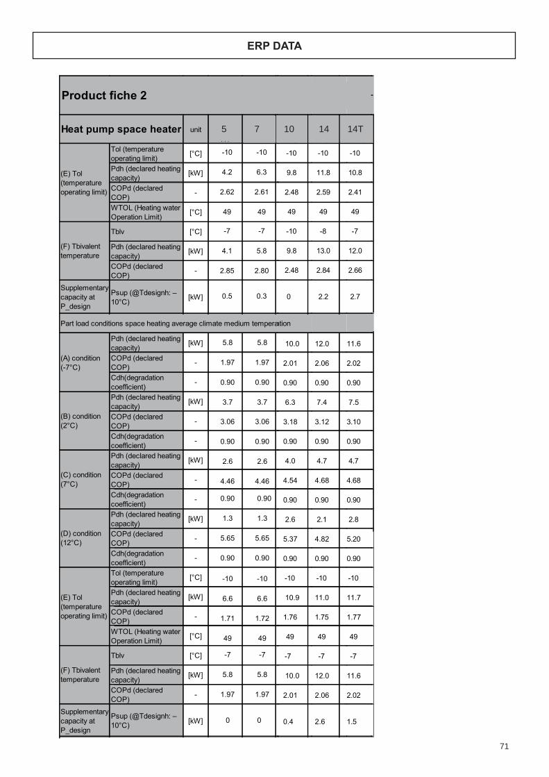
71
ERP DATA
56
unitMHC-
V5W/D2N1
MHC-V7W/D2
N1
MHC-V10W/D2N1-B
MHC-V12W/D2N1-B
MHC-V14W/D2N1-B
MHC-V16W/D2N1-B
MHC-V12W/D2RN1-B
MHC-V14W/D2RN1-B
MHC-V16W/D2RN1-B
Tol (temperatureoperating limit)
[°C] -10 -10 -10 -10 -10 -10 -10
Pdh (declared heatingcapacity)
[kW] 9.8 10.7 11.8 11.6 10.9 10.8 11.0
COPd (declaredCOP)
- 2.48 2.60 2.59 2.38 2.47 2.41 2.36
WTOL (Heating waterOperation Limit)
[°C] 49 49 49 49 49 49 49
Tblv [°C] -10 -7 -8 -6 -7 -7 -5
Pdh (declared heatingcapacity)
[kW] 9.8 11.4 13.0 13.9 10.6 12.0 13.0
COPd (declaredCOP)
- 2.48 2.92 2.84 2.80 2.83 2.66 2.90
Supplementarycapacity atP_design
Psup (@Tdesignh: –10°C)
[kW] 0 2.1 2.2 4.8 1.1 2.7 5.2
(A) condition (-7°C)
Pdh (declared heatingcapacity)
[kW] 10.0 10.0 12.0 12.3 9.7 11.6 11.7
COPd (declaredCOP)
- 2.01 2.01 2.06 2.02 2.00 2.02 1.99
Cdh(degradationcoefficient)
- 0.90 0.90 0.90 0.90 0.90 0.90 0.90
Pdh (declared heatingcapacity)
[kW] 6.3 6.3 7.4 7.9 6.2 7.5 7.8
COPd (declaredCOP)
- 3.18 3.18 3.12 3.05 3.21 3.10 3.02
Cdh(degradationcoefficient)
- 0.90 0.90 0.90 0.90 0.90 0.90 0.90
Pdh (declared heatingcapacity)
[kW] 4.0 4.0 4.7 5.1 4.1 4.7 5.1
COPd (declaredCOP)
- 4.54 4.53 4.68 4.57 4.67 4.68 4.70
Cdh(degradationcoefficient)
- 0.90 0.90 0.90 0.90 0.90 0.90 0.90
Pdh (declared heatingcapacity)
[kW] 2.6 2.6 2.1 2.1 3.0 2.8 2.8
COPd (declaredCOP)
- 5.37 5.37 4.82 4.77 5.68 5.20 5.28
Cdh(degradationcoefficient)
- 0.90 0.90 0.90 0.90 0.90 0.90 0.90
Tol (temperatureoperating limit)
[°C] -10 -10 -10 -10 -10 -10 -10
Pdh (declared heatingcapacity)
[kW] 10.9 10.9 11.0 10.2 11.5 11.7 10.6
COPd (declaredCOP)
- 1.76 1.76 1.75 1.68 1.76 1.77 1.78
WTOL (Heating waterOperation Limit)
[°C] 49 49 49 49 49 49 49
Tblv [°C] -7 -7 -7 -7 -7 -7 -6
Pdh (declared heatingcapacity)
[kW] 10.0 10.0 12.0 12.3 9.7 11.6 12.1
COPd (declaredCOP)
- 2.01 2.01 2.06 2.02 2.00 2.02 2.09
Supplementarycapacity atP_design
Psup (@Tdesignh: –10°C) [kW] 0.4 0.4 2.6 3.7 0 1.5 3.7
Product fiche 2
Heat pump space heater
(B) condition(2°C)
(E) Tol(temperatureoperating limit)
(F) Tbivalenttemperature
Part load conditions space heating average climate medium temperature application
(C) condition(7°C)
(D) condition(12°C)
(E) Tol(temperatureoperating limit)
(F) Tbivalenttemperature
-10 -10
4.2 6.3
2.62 2.61
49 49
-7 -7
4.1 5.8
2.85 2.80
0.5 0.3
5.8 5.8
1.97 1.97
0.90 0.90
3.7 3.7
3.06 3.06
0.90 0.90
2.6 2.6
4.46 4.46
0.90 0.90
1.3 1.3
5.65 5.65
0.90 0.90
-10 -10
6.6 6.6
1.71 1.72
49 49
-7 -7
5.8 5.8
1.97 1.97
0 0
MHC-V9W/D2
N1
-10
7.5
2.39
49
-7
7.8
2.45
1.4
7.7
1.98
0.90
4.9
3.02
0.90
3.2
4.67
0.90
1.4
6.16
0.90
-10
7.0
1.78
49
-7
7.7
1.98
1.7
5 7 10 14 14T
59
0.90
unitMHC-
V5W/D2N1
MHC-V7W/D2
N1
MHC-V9W/D2N1
MHC-V10W/D2N1-B
MHC-V12W/D2N1-B
MHC-V14W/D2N1-B
MHC-V16W/D2
N1-B
MHC-V12W/D2
RN1-B
MHC-V14W/D2
RN1-B
Pdh (declared heatingcapacity)
[kW] 10.1 12.9 14.0 14.0 12.4 13.7 12.6
COPd (declaredCOP)
- 3.89 3.53 2.98 2.98 3.45 3.21 2.94
Cdh(degradationcoefficient)
- 0.90 0.90 0.90 0.90 0.90 0.90 0.90
Pdh (declared heatingcapacity)
[kW] 6.7 7.9 9.3 9.3 7.8 9.2 9.7
COPd (declaredCOP)
- 5.61 5.47 5.17 5.17 5.54 5.31 5.29
Cdh(degradationcoefficient)
- 0.9 0.90 0.9 0.90 0.9 0.90 0.9
Pdh (declared heatingcapacity)
[kW] 3.9 3.5 4.2 4.2 3.9 3.8 4.3
COPd (declaredCOP)
- 10.18 8.38 8.01 8.01 7.91 7.51 7.06
Cdh(degradationcoefficient)
- 0.90 0.90 0.90 0.90 0.90 0.90 0.90
Tol (temperatureoperating limit) [°C] 2 2 2 2 2 2 2
Pdh (declared heatingcapacity)
[kW] 10.1 12.9 14.0 14.0 12.4 13.7 12.6
COPd (declaredCOP)
- 3.89 3.53 2.98 2.98 3.45 3.21 2.94
WTOL (Heating waterOperation Limit)
[°C] 60 60 60 60 60 60 60
Tblv [°C] 7 7 7 7 7 7 7
Pdh (declared heatingcapacity)
[kW] 6.7 7.9 9.3 9.3 7.8 9.2 9.7
COPd (declaredCOP)
- 5.61 5.47 5.17 5.17 5.54 5.31 5.29
Supplementarycapacity atP_design
Psup (@Tdesignh: 2°C)
[kW] 0.3 0 0.5 0.8 0 0.6 2.6
Pdh (declared heatingcapacity)
[kW] 10.2 12.5 12.5 14.3 12.2 12.2 13.8
COPd (declaredCOP)
- 2.35 2.37 2.37 2.27 2.42 2.42 2.43
Cdh(degradationcoefficient)
- 0.900.90 0.90 0.90 0.90 0.90 0.90
Pdh (declared heatingcapacity)
[kW] 6.6 7.7 7.7 9.2 8.0 8.0 9.9
COPd (declaredCOP)
- 3.38 3.37 3.37 3.33 3.50 3.50 3.66
Cdh(degradationcoefficient)
- 0.90 0.90 0.90 0.90 0.90 0.90 0.90
Pdh (declared heatingcapacity) [kW] 3.0 3.6 3.6 4.2 3.4 3.4 4.6
COPd (declaredCOP)
- 4.95 5.35 5.35 5.62 5.25 5.25 5.96
Cdh(degradationcoefficient)
- 0.90 0.90 0.90 0.90 0.90 0.90 0.90
Tol (temperatureoperating limit)
[°C] 2 2 2 2 2 2 2
Pdh (declared heatingcapacity)
[kW] 10.2 12.5 12.5 14.3 12.2 12.2 13.8
COPd (declaredCOP)
- 2.35 2.37 2.37 2.27 2.42 2.42 2.43
WTOL (Heating waterOperation Limit)
[°C] 60 60 60 60 60 60 60
Product fiche 5
Heat pump space heater
(D) condition(12°C)
Part load conditions space heating warmer climate low temperature application
(B) condition(2°C)
(C) condition(7°C)
(D) condition(12°C)
(E) Tol(temperatureoperating limit)
(F) Tbivalenttemperature
Part load conditions space heating warmer climate medium temperature application
(B) condition(2°C)
(C) condition(7°C)
(E) Tol(temperatureoperating limit)
4.7 6.6
3.82 3.45
3.1 4.2
0.90
2.1
5.70 5.59
0.90 0.90
7.76 8.15
1.3
6.6
0.90 0.90
2 2
3.82 3.45
4.7
4.2
60 60
7 7
5.70 5.59
3.1
0.90
4.7 6.8
2.07 2.18
3.0 4.4
0.90
2.1
3.29 3.45
0.90 0.90
4.74 6.01
1.4
6.8
0.90 0.90
2 2
2.07 2.18
4.7
60 60
0.1 0
MHC-V16W/D2
RN1-B
0.90
8.3
2.71
5.7
2.8
5.30
0.90
8.67
8.3
0.90
2
2.71
5.7
60
7
5.30
8.5
0.6
5.8
2.22
0.90
3.62
5.76
0.90
2.5
0.90
2.22
2
8.5
60
5 7 10 14 14T5 7 10 14 14T

72
ERP DATA
57
unitMHC-
V5W/D2N1
MHC-V7W/D2
N1
MHC-V9W/D2N1
MHC-V10W/D2N1-B
MHC-V12W/D2N1-B
MHC-V14W/D2N1-B
MHC-V16W/D2
N1-B
MHC-V12W/D2
RN1-B
MHC-V14W/D2
RN1-B
Prated (declaredheating capacity) @ –22°C
[kW] 11 12 14 16 12 14 16
Seasonal spaceheating efficiency (ηs) [%] 132 144 136 131 145 145 121
Annual energyconsumption [kWh] 7,747 8,175 10,032 12,145 8,515 9,430 12,724
Prated (declaredheating capacity) @ –22°C
[kW] 10 11 12 15 11 12 15
Seasonal spaceheating efficiency (ηs) [%] 99 94 94 99 108 108 111
Annual energyconsumption [kWh] 9,946 12,303 12,303 14,341 10,958 10,956 13,021
condition (-15°C)
Pdh (declared heatingcapacity)
[kW] 8.6 9.8 9.9 9.9 10.0 10.3 9.6
COPd (declaredCOP)
- 2.35 2.33 2.21 2.21 2.43 2.42 2.15
Cdh(degradationcoefficient)
- 0.90 0.90 0.90 0.90 0.90 0.90 0.90
(A) condition (-7°C)
Pdh (declared heatingcapacity)
[kW] 6.3 7.5 8.9 10.0 7.6 9.2 9.4
COPd (declaredCOP)
- 3.11 3.14 2.90 2.81 3.19 3.15 2.74
Cdh(degradationcoefficient)
- 0.90 0.90 0.90 0.90 0.90 0.90 0.90
Pdh (declared heatingcapacity)
[kW] 3.8 4.7 5.2 6.2 4.7 6.0 6.3
COPd (declaredCOP)
- 4.01 4.44 4.19 4.12 4.57 4.55 3.66
Cdh(degradationcoefficient)
- 0.90 0.90 0.90 0.90 0.90 0.90 0.90
Pdh (declared heatingcapacity)
[kW] 2.4 3.0 3.4 4.0 3.0 3.5 4.0
COPd (declaredCOP)
- 5.82 6.10 5.85 5.91 6.06 6.03 5.47
Cdh(degradationcoefficient)
- 0.90 0.90 0.90 0.90 0.90 0.90 0.90
Pdh (declared heatingcapacity)
[kW] 1.1 2.9 4.4 2.7 2.6 2.6 3.1
COPd (declaredCOP)
- 3.56 8.92 8.72 6.88 5.76 5.65 6.10
Cdh(degradationcoefficient)
- 0.90 0.90 0.90 0.90 0.90 0.90 0.90
Tol (temperatureoperating limit)
[°C] -20 -20 -20 -20 -20 -20 -20
Pdh (declared heatingcapacity)
[kW] 8.28.2 8.3 7.6 8.4 8.4 7.6
COPd (declaredCOP)
- 1.87 1.85 1.88 1.68 2.02 2.00 1.73
WTOL (Heating waterOperation Limit)
[°C] 40 40 40 40 40 40 40
Tblv [°C] -15 -15 -12 -11 -14 -13 -11
Pdh (declared heatingcapacity)
[kW] 8.6 9.8 10.4 11.8 10.1 10.8 11.4
COPd (declaredCOP)
- 2.35 2.33 2.36 2.51 2.50 2.58 2.42
Supplementarycapacity atP_design
Psup (@Tdesignh: –22°C) [kW] 1.8 3.2 5.0 8.9 3.7 4.9 7.5
Product fiche 3
(C) condition(7°C)
Colder climate (Design temperature = –22°C)
Space heating35°C
Space heating55°C
Part load conditions space heating colder climate low temperature application
(B) condition(2°C)
Heat pump space heater
(D) condition(12°C)
(E) Tol(temperatureoperating limit)
(F) Tbivalenttemperature
5 7
133 158
3,331 4,116
5 7
100 106
4,459 6,436
3.7 5.5
2.23 2.41
0.90 0.90
2.7 4.0
3.04 3.25
0.90 0.90
1.6 2.5
3.91 5.16
0.90 0.90
1.3 1.8
5.98 7.13
0.90 0.90
1.2 1.1
8.59 7.57
0.90 0.90
-20 -20
4.5 4.9
1.83 2.00
40 40
-15 -15
3.7 5.5
2.23 2.41
0 1.5
MHC-V16W/D2
RN1-B
9
147
5717
9
110
7622
6.6
2.20
0.90
5.5
3.08
0.90
3.2
4.56
0.90
2.2
6.39
0.90
1.3
8.13
0.90
-20
5.3
1.86
40
-14
6.8
2.23
3.4
5 7 10 14 14T
57
unitMHC-
V5W/D2N1
MHC-V7W/D2
N1
MHC-V9W/D2N1
MHC-V10W/D2N1-B
MHC-V12W/D2N1-B
MHC-V14W/D2N1-B
MHC-V16W/D2
N1-B
MHC-V12W/D2
RN1-B
MHC-V14W/D2
RN1-B
Prated (declaredheating capacity) @ –22°C
[kW] 11 12 14 16 12 14 16
Seasonal spaceheating efficiency (ηs) [%] 132 144 136 131 145 145 121
Annual energyconsumption [kWh] 7,747 8,175 10,032 12,145 8,515 9,430 12,724
Prated (declaredheating capacity) @ –22°C
[kW] 10 11 12 15 11 12 15
Seasonal spaceheating efficiency (ηs) [%] 99 94 94 99 108 108 111
Annual energyconsumption [kWh] 9,946 12,303 12,303 14,341 10,958 10,956 13,021
condition (-15°C)
Pdh (declared heatingcapacity)
[kW] 8.6 9.8 9.9 9.9 10.0 10.3 9.6
COPd (declaredCOP)
- 2.35 2.33 2.21 2.21 2.43 2.42 2.15
Cdh(degradationcoefficient) - 0.90 0.90 0.90 0.90 0.90 0.90 0.90
(A) condition (-7°C)
Pdh (declared heatingcapacity)
[kW] 6.3 7.5 8.9 10.0 7.6 9.2 9.4
COPd (declaredCOP)
- 3.11 3.14 2.90 2.81 3.19 3.15 2.74
Cdh(degradationcoefficient)
- 0.90 0.90 0.90 0.90 0.90 0.90 0.90
Pdh (declared heatingcapacity)
[kW] 3.8 4.7 5.2 6.2 4.7 6.0 6.3
COPd (declaredCOP)
- 4.01 4.44 4.19 4.12 4.57 4.55 3.66
Cdh(degradationcoefficient)
- 0.90 0.90 0.90 0.90 0.90 0.90 0.90
Pdh (declared heatingcapacity)
[kW] 2.4 3.0 3.4 4.0 3.0 3.5 4.0
COPd (declaredCOP)
- 5.82 6.10 5.85 5.91 6.06 6.03 5.47
Cdh(degradationcoefficient)
- 0.90 0.90 0.90 0.90 0.90 0.90 0.90
Pdh (declared heatingcapacity)
[kW] 1.1 2.9 4.4 2.7 2.6 2.6 3.1
COPd (declaredCOP)
- 3.56 8.92 8.72 6.88 5.76 5.65 6.10
Cdh(degradationcoefficient)
- 0.90 0.90 0.90 0.90 0.90 0.90 0.90
Tol (temperatureoperating limit)
[°C] -20 -20 -20 -20 -20 -20 -20
Pdh (declared heatingcapacity)
[kW] 8.28.2 8.3 7.6 8.4 8.4 7.6
COPd (declaredCOP)
- 1.87 1.85 1.88 1.68 2.02 2.00 1.73
WTOL (Heating waterOperation Limit)
[°C] 40 40 40 40 40 40 40
Tblv [°C] -15 -15 -12 -11 -14 -13 -11
Pdh (declared heatingcapacity)
[kW] 8.6 9.8 10.4 11.8 10.1 10.8 11.4
COPd (declaredCOP)
- 2.35 2.33 2.36 2.51 2.50 2.58 2.42
Supplementarycapacity atP_design
Psup (@Tdesignh: –22°C) [kW] 1.8 3.2 5.0 8.9 3.7 4.9 7.5
Product fiche 3
(C) condition(7°C)
Colder climate (Design temperature = –22°C)
Space heating35°C
Space heating55°C
Part load conditions space heating colder climate low temperature application
(B) condition(2°C)
Heat pump space heater
(D) condition(12°C)
(E) Tol(temperatureoperating limit)
(F) Tbivalenttemperature
5 7
133 158
3,331 4,116
5 7
100 106
4,459 6,436
3.7 5.5
2.23 2.41
0.90 0.90
2.7 4.0
3.04 3.25
0.90 0.90
1.6 2.5
3.91 5.16
0.90 0.90
1.3 1.8
5.98 7.13
0.90 0.90
1.2 1.1
8.59 7.57
0.90 0.90
-20 -20
4.5 4.9
1.83 2.00
40 40
-15 -15
3.7 5.5
2.23 2.41
0 1.5
MHC-V16W/D2
RN1-B
9
147
5717
9
110
7622
6.6
2.20
0.90
5.5
3.08
0.90
3.2
4.56
0.90
2.2
6.39
0.90
1.3
8.13
0.90
-20
5.3
1.86
40
-14
6.8
2.23
3.4
5 7 10 14 14T
59
0.90
unitMHC-
V5W/D2N1
MHC-V7W/D2
N1
MHC-V9W/D2N1
MHC-V10W/D2N1-B
MHC-V12W/D2N1-B
MHC-V14W/D2N1-B
MHC-V16W/D2
N1-B
MHC-V12W/D2
RN1-B
MHC-V14W/D2
RN1-B
Pdh (declared heatingcapacity)
[kW] 10.1 12.9 14.0 14.0 12.4 13.7 12.6
COPd (declaredCOP)
- 3.89 3.53 2.98 2.98 3.45 3.21 2.94
Cdh(degradationcoefficient)
- 0.90 0.90 0.90 0.90 0.90 0.90 0.90
Pdh (declared heatingcapacity)
[kW] 6.7 7.9 9.3 9.3 7.8 9.2 9.7
COPd (declaredCOP)
- 5.61 5.47 5.17 5.17 5.54 5.31 5.29
Cdh(degradationcoefficient)
- 0.9 0.90 0.9 0.90 0.9 0.90 0.9
Pdh (declared heatingcapacity)
[kW] 3.9 3.5 4.2 4.2 3.9 3.8 4.3
COPd (declaredCOP)
- 10.18 8.38 8.01 8.01 7.91 7.51 7.06
Cdh(degradationcoefficient)
- 0.90 0.90 0.90 0.90 0.90 0.90 0.90
Tol (temperatureoperating limit) [°C] 2 2 2 2 2 2 2
Pdh (declared heatingcapacity)
[kW] 10.1 12.9 14.0 14.0 12.4 13.7 12.6
COPd (declaredCOP)
- 3.89 3.53 2.98 2.98 3.45 3.21 2.94
WTOL (Heating waterOperation Limit)
[°C] 60 60 60 60 60 60 60
Tblv [°C] 7 7 7 7 7 7 7
Pdh (declared heatingcapacity)
[kW] 6.7 7.9 9.3 9.3 7.8 9.2 9.7
COPd (declaredCOP)
- 5.61 5.47 5.17 5.17 5.54 5.31 5.29
Supplementarycapacity atP_design
Psup (@Tdesignh: 2°C)
[kW] 0.3 0 0.5 0.8 0 0.6 2.6
Pdh (declared heatingcapacity)
[kW] 10.2 12.5 12.5 14.3 12.2 12.2 13.8
COPd (declaredCOP)
- 2.35 2.37 2.37 2.27 2.42 2.42 2.43
Cdh(degradationcoefficient)
- 0.900.90 0.90 0.90 0.90 0.90 0.90
Pdh (declared heatingcapacity)
[kW] 6.6 7.7 7.7 9.2 8.0 8.0 9.9
COPd (declaredCOP)
- 3.38 3.37 3.37 3.33 3.50 3.50 3.66
Cdh(degradationcoefficient)
- 0.90 0.90 0.90 0.90 0.90 0.90 0.90
Pdh (declared heatingcapacity) [kW] 3.0 3.6 3.6 4.2 3.4 3.4 4.6
COPd (declaredCOP)
- 4.95 5.35 5.35 5.62 5.25 5.25 5.96
Cdh(degradationcoefficient)
- 0.90 0.90 0.90 0.90 0.90 0.90 0.90
Tol (temperatureoperating limit)
[°C] 2 2 2 2 2 2 2
Pdh (declared heatingcapacity)
[kW] 10.2 12.5 12.5 14.3 12.2 12.2 13.8
COPd (declaredCOP)
- 2.35 2.37 2.37 2.27 2.42 2.42 2.43
WTOL (Heating waterOperation Limit)
[°C] 60 60 60 60 60 60 60
Product fiche 5
Heat pump space heater
(D) condition(12°C)
Part load conditions space heating warmer climate low temperature application
(B) condition(2°C)
(C) condition(7°C)
(D) condition(12°C)
(E) Tol(temperatureoperating limit)
(F) Tbivalenttemperature
Part load conditions space heating warmer climate medium temperature application
(B) condition(2°C)
(C) condition(7°C)
(E) Tol(temperatureoperating limit)
4.7 6.6
3.82 3.45
3.1 4.2
0.90
2.1
5.70 5.59
0.90 0.90
7.76 8.15
1.3
6.6
0.90 0.90
2 2
3.82 3.45
4.7
4.2
60 60
7 7
5.70 5.59
3.1
0.90
4.7 6.8
2.07 2.18
3.0 4.4
0.90
2.1
3.29 3.45
0.90 0.90
4.74 6.01
1.4
6.8
0.90 0.90
2 2
2.07 2.18
4.7
60 60
0.1 0
MHC-V16W/D2
RN1-B
0.90
8.3
2.71
5.7
2.8
5.30
0.90
8.67
8.3
0.90
2
2.71
5.7
60
7
5.30
8.5
0.6
5.8
2.22
0.90
3.62
5.76
0.90
2.5
0.90
2.22
2
8.5
60
5 7 10 14 14T5 7 10 14 14T

73
ERP DATA
58
unitMHC-
V5W/D2N1
MHC-V7W/D2
N1
MHC-V9W/D2N1
MHC-V10W/D2N1-B
MHC-V12W/D2N1-B
MHC-V14W/D2N1-B
MHC-V16W/D2
N1-B
MHC-V12W/D2
RN1-B
MHC-V14W/D2
RN1-B
Pdh (declared heatingcapacity) [kW] 8.4 10.1 10.1 9.0 9.3 9.3 9.2
COPd (declaredCOP)
- 1.68 1.82 1.82 1.64 1.80 1.80 1.72
Cdh(degradationcoefficient)
- 0.90 0.90 0.90 0.90 0.90 0.90 0.90
Pdh (declared heatingcapacity)
[kW] 6.2 7.8 7.8 8.8 7.8 7.8 9.3
COPd (declaredCOP)
- 2.17 2.14 2.14 2.20 2.32 2.32 2.34
Cdh(degradationcoefficient)
- 0.90 0.90 0.90 0.90 0.90 0.90 0.90
Pdh (declared heatingcapacity)
[kW] 3.9 4.4 4.4 5.3 4.5 4.5 5.7
COPd (declaredCOP)
- 3.00 2.77 2.77 3.20 3.35 3.35 3.53
Cdh(degradationcoefficient)
- 0.90 0.90 0.90 0.90 0.90 0.90 0.90
Pdh (declared heatingcapacity)
[kW] 2.5 2.9 2.9 3.4 2.9 2.9 3.6
COPd (declaredCOP)
- 4.09 4.16 4.16 4.52 4.44 4.44 4.68
Cdh(degradationcoefficient)
- 0.90 0.90 0.90 0.90 0.90 0.90 0.90
Pdh (declared heatingcapacity)
[kW] 1.2 1.3 1.3 2.5 2.4 2.4 3.6
COPd (declaredCOP)
- 3.10 3.33 3.33 6.41 4.73 4.73 7.08
Cdh(degradationcoefficient)
- 0.90 0.90 0.90 0.90 0.90 0.90 0.90
Tol (temperatureoperating limit)
[°C] -20 -20 -20 -20 -20 -20 -20
Pdh (declared heatingcapacity)
[kW] 7.1 7.1 7.1 6.4 7.3 7.3 7.0
COPd (declaredCOP)
- 1.31 1.29 1.29 1.16 1.40 1.40 1.34
WTOL (Heating waterOperation Limit)
[°C] 40 40 40 40 40 40 40
Tblv [°C] -15 -11 -11 -11 -14 -14 -11
Pdh (declared heatingcapacity)
[kW] 8.4 8.6 8.6 10.6 9.8 9.8 10.7
COPd (declaredCOP)
- 1.68 1.59 1.59 1.86 1.89 1.89 1.99
Supplementarycapacity atP_design
Psup (@Tdesignh: –22°C) [kW] 2.6 4.4 4.4 8.5 4.4 4.4 7.2
Prated (declaredheating capacity) @ 2°C
[kW] 10 12 14 15 12 14 15
Seasonal spaceheating efficiency (ηs)
[%] 272 251 237 218 250 188 212
Annual energyconsumption
[kWh] 2,021 2,565 3,223 3,569 2,580 4,023 3,756
Prated (declaredheating capacity) @ 2°C
[kW] 10 12 12 15 12 12 15
Seasonal spaceheating efficiency (ηs)
[%] 153 159 160 155 149 147 169
Annual energyconsumption
[kWh] 3,534 3,967 3,928 4,963 4,386 4,445 4,773
Product fiche 4
Heat pump space heater
Warmer climate (Design temperature =2°C)
Part load conditions space heating colder climate medium temperature application
condition (-15°C)
(A) condition (-7°C)
(B) condition(2°C)
(C) condition(7°C)
(D) condition(12°C)
(E) Tol(temperatureoperating limit)
(F) Tbivalenttemperature
Space heating35°C
Space heating55°C
3.8 5.0
1.66 1.66
0.90 0.90
3.0 4.4
2.12 2.26
0.90 0.90
1.7 2.5
3.01 3.43
0.90 0.90
1.2 1.6
3.91 4.39
0.90 0.90
1.1 1.0
5.84 5.39
0.90 0.90
-20 -20
4.2 4.2
1.37 1.34
40 40
-15 -13
3.8 5.4
1.66 1.77
0.2 2.5
5 7
229 248
1,105 1,392
5 7
145 167
1,660 2,121
MHC-V16W/D2
RN1-B
6.1
1.79
0.90
5.4
2.32
0.90
3.2
3.38
0.90
2.1
4.87
0.90
1.1
6.25
0.90
-20
4.5
1.38
40
-12
6.4
1.93
4.2
8
245
1,791
8
167
2,668
5 7 10 14 14T
58
unitMHC-
V5W/D2N1
MHC-V7W/D2
N1
MHC-V9W/D2N1
MHC-V10W/D2N1-B
MHC-V12W/D2N1-B
MHC-V14W/D2N1-B
MHC-V16W/D2
N1-B
MHC-V12W/D2
RN1-B
MHC-V14W/D2
RN1-B
Pdh (declared heatingcapacity) [kW] 8.4 10.1 10.1 9.0 9.3 9.3 9.2
COPd (declaredCOP)
- 1.68 1.82 1.82 1.64 1.80 1.80 1.72
Cdh(degradationcoefficient)
- 0.90 0.90 0.90 0.90 0.90 0.90 0.90
Pdh (declared heatingcapacity)
[kW] 6.2 7.8 7.8 8.8 7.8 7.8 9.3
COPd (declaredCOP)
- 2.17 2.14 2.14 2.20 2.32 2.32 2.34
Cdh(degradationcoefficient)
- 0.90 0.90 0.90 0.90 0.90 0.90 0.90
Pdh (declared heatingcapacity)
[kW] 3.9 4.4 4.4 5.3 4.5 4.5 5.7
COPd (declaredCOP)
- 3.00 2.77 2.77 3.20 3.35 3.35 3.53
Cdh(degradationcoefficient)
- 0.90 0.90 0.90 0.90 0.90 0.90 0.90
Pdh (declared heatingcapacity)
[kW] 2.5 2.9 2.9 3.4 2.9 2.9 3.6
COPd (declaredCOP)
- 4.09 4.16 4.16 4.52 4.44 4.44 4.68
Cdh(degradationcoefficient)
- 0.90 0.90 0.90 0.90 0.90 0.90 0.90
Pdh (declared heatingcapacity) [kW] 1.2 1.3 1.3 2.5 2.4 2.4 3.6
COPd (declaredCOP)
- 3.10 3.33 3.33 6.41 4.73 4.73 7.08
Cdh(degradationcoefficient)
- 0.90 0.90 0.90 0.90 0.90 0.90 0.90
Tol (temperatureoperating limit)
[°C] -20 -20 -20 -20 -20 -20 -20
Pdh (declared heatingcapacity)
[kW] 7.1 7.1 7.1 6.4 7.3 7.3 7.0
COPd (declaredCOP)
- 1.31 1.29 1.29 1.16 1.40 1.40 1.34
WTOL (Heating waterOperation Limit)
[°C] 40 40 40 40 40 40 40
Tblv [°C] -15 -11 -11 -11 -14 -14 -11
Pdh (declared heatingcapacity)
[kW] 8.4 8.6 8.6 10.6 9.8 9.8 10.7
COPd (declaredCOP)
- 1.68 1.59 1.59 1.86 1.89 1.89 1.99
Supplementarycapacity atP_design
Psup (@Tdesignh: –22°C) [kW] 2.6 4.4 4.4 8.5 4.4 4.4 7.2
Prated (declaredheating capacity) @ 2°C
[kW] 10 12 14 15 12 14 15
Seasonal spaceheating efficiency (ηs)
[%] 272 251 237 218 250 188 212
Annual energyconsumption
[kWh] 2,021 2,565 3,223 3,569 2,580 4,023 3,756
Prated (declaredheating capacity) @ 2°C
[kW] 10 12 12 15 12 12 15
Seasonal spaceheating efficiency (ηs) [%] 153 159 160 155 149 147 169
Annual energyconsumption
[kWh] 3,534 3,967 3,928 4,963 4,386 4,445 4,773
Product fiche 4
Heat pump space heater
Warmer climate (Design temperature =2°C)
Part load conditions space heating colder climate medium temperature application
condition (-15°C)
(A) condition (-7°C)
(B) condition(2°C)
(C) condition(7°C)
(D) condition(12°C)
(E) Tol(temperatureoperating limit)
(F) Tbivalenttemperature
Space heating35°C
Space heating55°C
3.8 5.0
1.66 1.66
0.90 0.90
3.0 4.4
2.12 2.26
0.90 0.90
1.7 2.5
3.01 3.43
0.90 0.90
1.2 1.6
3.91 4.39
0.90 0.90
1.1 1.0
5.84 5.39
0.90 0.90
-20 -20
4.2 4.2
1.37 1.34
40 40
-15 -13
3.8 5.4
1.66 1.77
0.2 2.5
5 7
229 248
1,105 1,392
5 7
145 167
1,660 2,121
MHC-V16W/D2
RN1-B
6.1
1.79
0.90
5.4
2.32
0.90
3.2
3.38
0.90
2.1
4.87
0.90
1.1
6.25
0.90
-20
4.5
1.38
40
-12
6.4
1.93
4.2
8
245
1,791
8
167
2,668
5 7 10 14 14T
59
0.90
unitMHC-
V5W/D2N1
MHC-V7W/D2
N1
MHC-V9W/D2N1
MHC-V10W/D2N1-B
MHC-V12W/D2N1-B
MHC-V14W/D2N1-B
MHC-V16W/D2
N1-B
MHC-V12W/D2
RN1-B
MHC-V14W/D2
RN1-B
Pdh (declared heatingcapacity)
[kW] 10.1 12.9 14.0 14.0 12.4 13.7 12.6
COPd (declaredCOP)
- 3.89 3.53 2.98 2.98 3.45 3.21 2.94
Cdh(degradationcoefficient)
- 0.90 0.90 0.90 0.90 0.90 0.90 0.90
Pdh (declared heatingcapacity)
[kW] 6.7 7.9 9.3 9.3 7.8 9.2 9.7
COPd (declaredCOP)
- 5.61 5.47 5.17 5.17 5.54 5.31 5.29
Cdh(degradationcoefficient)
- 0.9 0.90 0.9 0.90 0.9 0.90 0.9
Pdh (declared heatingcapacity)
[kW] 3.9 3.5 4.2 4.2 3.9 3.8 4.3
COPd (declaredCOP)
- 10.18 8.38 8.01 8.01 7.91 7.51 7.06
Cdh(degradationcoefficient)
- 0.90 0.90 0.90 0.90 0.90 0.90 0.90
Tol (temperatureoperating limit) [°C] 2 2 2 2 2 2 2
Pdh (declared heatingcapacity)
[kW] 10.1 12.9 14.0 14.0 12.4 13.7 12.6
COPd (declaredCOP)
- 3.89 3.53 2.98 2.98 3.45 3.21 2.94
WTOL (Heating waterOperation Limit)
[°C] 60 60 60 60 60 60 60
Tblv [°C] 7 7 7 7 7 7 7
Pdh (declared heatingcapacity)
[kW] 6.7 7.9 9.3 9.3 7.8 9.2 9.7
COPd (declaredCOP)
- 5.61 5.47 5.17 5.17 5.54 5.31 5.29
Supplementarycapacity atP_design
Psup (@Tdesignh: 2°C)
[kW] 0.3 0 0.5 0.8 0 0.6 2.6
Pdh (declared heatingcapacity)
[kW] 10.2 12.5 12.5 14.3 12.2 12.2 13.8
COPd (declaredCOP)
- 2.35 2.37 2.37 2.27 2.42 2.42 2.43
Cdh(degradationcoefficient)
- 0.900.90 0.90 0.90 0.90 0.90 0.90
Pdh (declared heatingcapacity)
[kW] 6.6 7.7 7.7 9.2 8.0 8.0 9.9
COPd (declaredCOP)
- 3.38 3.37 3.37 3.33 3.50 3.50 3.66
Cdh(degradationcoefficient)
- 0.90 0.90 0.90 0.90 0.90 0.90 0.90
Pdh (declared heatingcapacity) [kW] 3.0 3.6 3.6 4.2 3.4 3.4 4.6
COPd (declaredCOP)
- 4.95 5.35 5.35 5.62 5.25 5.25 5.96
Cdh(degradationcoefficient)
- 0.90 0.90 0.90 0.90 0.90 0.90 0.90
Tol (temperatureoperating limit)
[°C] 2 2 2 2 2 2 2
Pdh (declared heatingcapacity)
[kW] 10.2 12.5 12.5 14.3 12.2 12.2 13.8
COPd (declaredCOP)
- 2.35 2.37 2.37 2.27 2.42 2.42 2.43
WTOL (Heating waterOperation Limit)
[°C] 60 60 60 60 60 60 60
Product fiche 5
Heat pump space heater
(D) condition(12°C)
Part load conditions space heating warmer climate low temperature application
(B) condition(2°C)
(C) condition(7°C)
(D) condition(12°C)
(E) Tol(temperatureoperating limit)
(F) Tbivalenttemperature
Part load conditions space heating warmer climate medium temperature application
(B) condition(2°C)
(C) condition(7°C)
(E) Tol(temperatureoperating limit)
4.7 6.6
3.82 3.45
3.1 4.2
0.90
2.1
5.70 5.59
0.90 0.90
7.76 8.15
1.3
6.6
0.90 0.90
2 2
3.82 3.45
4.7
4.2
60 60
7 7
5.70 5.59
3.1
0.90
4.7 6.8
2.07 2.18
3.0 4.4
0.90
2.1
3.29 3.45
0.90 0.90
4.74 6.01
1.4
6.8
0.90 0.90
2 2
2.07 2.18
4.7
60 60
0.1 0
MHC-V16W/D2
RN1-B
0.90
8.3
2.71
5.7
2.8
5.30
0.90
8.67
8.3
0.90
2
2.71
5.7
60
7
5.30
8.5
0.6
5.8
2.22
0.90
3.62
5.76
0.90
2.5
0.90
2.22
2
8.5
60
5 7 10 14 14T5 7 10 14 14T

74
ERP DATA
59
0.90
unitMHC-
V5W/D2N1
MHC-V7W/D2
N1
MHC-V9W/D2N1
MHC-V10W/D2N1-B
MHC-V12W/D2N1-B
MHC-V14W/D2N1-B
MHC-V16W/D2
N1-B
MHC-V12W/D2
RN1-B
MHC-V14W/D2
RN1-B
Pdh (declared heatingcapacity)
[kW] 10.1 12.9 14.0 14.0 12.4 13.7 12.6
COPd (declaredCOP)
- 3.89 3.53 2.98 2.98 3.45 3.21 2.94
Cdh(degradationcoefficient)
- 0.90 0.90 0.90 0.90 0.90 0.90 0.90
Pdh (declared heatingcapacity)
[kW] 6.7 7.9 9.3 9.3 7.8 9.2 9.7
COPd (declaredCOP)
- 5.61 5.47 5.17 5.17 5.54 5.31 5.29
Cdh(degradationcoefficient)
- 0.9 0.90 0.9 0.90 0.9 0.90 0.9
Pdh (declared heatingcapacity)
[kW] 3.9 3.5 4.2 4.2 3.9 3.8 4.3
COPd (declaredCOP)
- 10.18 8.38 8.01 8.01 7.91 7.51 7.06
Cdh(degradationcoefficient)
- 0.90 0.90 0.90 0.90 0.90 0.90 0.90
Tol (temperatureoperating limit) [°C] 2 2 2 2 2 2 2
Pdh (declared heatingcapacity)
[kW] 10.1 12.9 14.0 14.0 12.4 13.7 12.6
COPd (declaredCOP)
- 3.89 3.53 2.98 2.98 3.45 3.21 2.94
WTOL (Heating waterOperation Limit)
[°C] 60 60 60 60 60 60 60
Tblv [°C] 7 7 7 7 7 7 7
Pdh (declared heatingcapacity)
[kW] 6.7 7.9 9.3 9.3 7.8 9.2 9.7
COPd (declaredCOP)
- 5.61 5.47 5.17 5.17 5.54 5.31 5.29
Supplementarycapacity atP_design
Psup (@Tdesignh: 2°C)
[kW] 0.3 0 0.5 0.8 0 0.6 2.6
Pdh (declared heatingcapacity)
[kW] 10.2 12.5 12.5 14.3 12.2 12.2 13.8
COPd (declaredCOP)
- 2.35 2.37 2.37 2.27 2.42 2.42 2.43
Cdh(degradationcoefficient)
- 0.900.90 0.90 0.90 0.90 0.90 0.90
Pdh (declared heatingcapacity)
[kW] 6.6 7.7 7.7 9.2 8.0 8.0 9.9
COPd (declaredCOP)
- 3.38 3.37 3.37 3.33 3.50 3.50 3.66
Cdh(degradationcoefficient)
- 0.90 0.90 0.90 0.90 0.90 0.90 0.90
Pdh (declared heatingcapacity) [kW] 3.0 3.6 3.6 4.2 3.4 3.4 4.6
COPd (declaredCOP)
- 4.95 5.35 5.35 5.62 5.25 5.25 5.96
Cdh(degradationcoefficient)
- 0.90 0.90 0.90 0.90 0.90 0.90 0.90
Tol (temperatureoperating limit)
[°C] 2 2 2 2 2 2 2
Pdh (declared heatingcapacity)
[kW] 10.2 12.5 12.5 14.3 12.2 12.2 13.8
COPd (declaredCOP)
- 2.35 2.37 2.37 2.27 2.42 2.42 2.43
WTOL (Heating waterOperation Limit)
[°C] 60 60 60 60 60 60 60
Product fiche 5
Heat pump space heater
(D) condition(12°C)
Part load conditions space heating warmer climate low temperature application
(B) condition(2°C)
(C) condition(7°C)
(D) condition(12°C)
(E) Tol(temperatureoperating limit)
(F) Tbivalenttemperature
Part load conditions space heating warmer climate medium temperature application
(B) condition(2°C)
(C) condition(7°C)
(E) Tol(temperatureoperating limit)
4.7 6.6
3.82 3.45
3.1 4.2
0.90
2.1
5.70 5.59
0.90 0.90
7.76 8.15
1.3
6.6
0.90 0.90
2 2
3.82 3.45
4.7
4.2
60 60
7 7
5.70 5.59
3.1
0.90
4.7 6.8
2.07 2.18
3.0 4.4
0.90
2.1
3.29 3.45
0.90 0.90
4.74 6.01
1.4
6.8
0.90 0.90
2 2
2.07 2.18
4.7
60 60
0.1 0
MHC-V16W/D2
RN1-B
0.90
8.3
2.71
5.7
2.8
5.30
0.90
8.67
8.3
0.90
2
2.71
5.7
60
7
5.30
8.5
0.6
5.8
2.22
0.90
3.62
5.76
0.90
2.5
0.90
2.22
2
8.5
60
5 7 10 14 14T
59
0.90
unitMHC-
V5W/D2N1
MHC-V7W/D2
N1
MHC-V9W/D2N1
MHC-V10W/D2N1-B
MHC-V12W/D2N1-B
MHC-V14W/D2N1-B
MHC-V16W/D2
N1-B
MHC-V12W/D2
RN1-B
MHC-V14W/D2
RN1-B
Pdh (declared heatingcapacity)
[kW] 10.1 12.9 14.0 14.0 12.4 13.7 12.6
COPd (declaredCOP)
- 3.89 3.53 2.98 2.98 3.45 3.21 2.94
Cdh(degradationcoefficient)
- 0.90 0.90 0.90 0.90 0.90 0.90 0.90
Pdh (declared heatingcapacity)
[kW] 6.7 7.9 9.3 9.3 7.8 9.2 9.7
COPd (declaredCOP)
- 5.61 5.47 5.17 5.17 5.54 5.31 5.29
Cdh(degradationcoefficient)
- 0.9 0.90 0.9 0.90 0.9 0.90 0.9
Pdh (declared heatingcapacity)
[kW] 3.9 3.5 4.2 4.2 3.9 3.8 4.3
COPd (declaredCOP)
- 10.18 8.38 8.01 8.01 7.91 7.51 7.06
Cdh(degradationcoefficient)
- 0.90 0.90 0.90 0.90 0.90 0.90 0.90
Tol (temperatureoperating limit) [°C] 2 2 2 2 2 2 2
Pdh (declared heatingcapacity)
[kW] 10.1 12.9 14.0 14.0 12.4 13.7 12.6
COPd (declaredCOP)
- 3.89 3.53 2.98 2.98 3.45 3.21 2.94
WTOL (Heating waterOperation Limit)
[°C] 60 60 60 60 60 60 60
Tblv [°C] 7 7 7 7 7 7 7
Pdh (declared heatingcapacity)
[kW] 6.7 7.9 9.3 9.3 7.8 9.2 9.7
COPd (declaredCOP)
- 5.61 5.47 5.17 5.17 5.54 5.31 5.29
Supplementarycapacity atP_design
Psup (@Tdesignh: 2°C)
[kW] 0.3 0 0.5 0.8 0 0.6 2.6
Pdh (declared heatingcapacity)
[kW] 10.2 12.5 12.5 14.3 12.2 12.2 13.8
COPd (declaredCOP)
- 2.35 2.37 2.37 2.27 2.42 2.42 2.43
Cdh(degradationcoefficient)
- 0.900.90 0.90 0.90 0.90 0.90 0.90
Pdh (declared heatingcapacity)
[kW] 6.6 7.7 7.7 9.2 8.0 8.0 9.9
COPd (declaredCOP)
- 3.38 3.37 3.37 3.33 3.50 3.50 3.66
Cdh(degradationcoefficient)
- 0.90 0.90 0.90 0.90 0.90 0.90 0.90
Pdh (declared heatingcapacity) [kW] 3.0 3.6 3.6 4.2 3.4 3.4 4.6
COPd (declaredCOP)
- 4.95 5.35 5.35 5.62 5.25 5.25 5.96
Cdh(degradationcoefficient)
- 0.90 0.90 0.90 0.90 0.90 0.90 0.90
Tol (temperatureoperating limit)
[°C] 2 2 2 2 2 2 2
Pdh (declared heatingcapacity)
[kW] 10.2 12.5 12.5 14.3 12.2 12.2 13.8
COPd (declaredCOP)
- 2.35 2.37 2.37 2.27 2.42 2.42 2.43
WTOL (Heating waterOperation Limit)
[°C] 60 60 60 60 60 60 60
Product fiche 5
Heat pump space heater
(D) condition(12°C)
Part load conditions space heating warmer climate low temperature application
(B) condition(2°C)
(C) condition(7°C)
(D) condition(12°C)
(E) Tol(temperatureoperating limit)
(F) Tbivalenttemperature
Part load conditions space heating warmer climate medium temperature application
(B) condition(2°C)
(C) condition(7°C)
(E) Tol(temperatureoperating limit)
4.7 6.6
3.82 3.45
3.1 4.2
0.90
2.1
5.70 5.59
0.90 0.90
7.76 8.15
1.3
6.6
0.90 0.90
2 2
3.82 3.45
4.7
4.2
60 60
7 7
5.70 5.59
3.1
0.90
4.7 6.8
2.07 2.18
3.0 4.4
0.90
2.1
3.29 3.45
0.90 0.90
4.74 6.01
1.4
6.8
0.90 0.90
2 2
2.07 2.18
4.7
60 60
0.1 0
MHC-V16W/D2
RN1-B
0.90
8.3
2.71
5.7
2.8
5.30
0.90
8.67
8.3
0.90
2
2.71
5.7
60
7
5.30
8.5
0.6
5.8
2.22
0.90
3.62
5.76
0.90
2.5
0.90
2.22
2
8.5
60
5 7 10 14 14T5 7 10 14 14T

75
ERP DATA
60
unitMHC-
V5W/D2N1
MHC-V7W/D2
N1
MHC-V9W/D2N1
MHC-V10W/D2N1-B
MHC-V12W/D2N1-B
MHC-V14W/D2N1-B
MHC-V16W/D2
N1-B
MHC-V12W/D2
RN1-B
MHC-V14W/D2
RN1-B
Tblv [°C] 7 7 7 7 7 7 7
Pdh (declared heatingcapacity)
[kW] 6.6 7.7 7.7 9.2 8.0 8.0 9.9
COPd (declaredCOP)
- 3.38 3.37 3.37 3.33 3.50 3.50 3.66
Supplementarycapacity atP_design
Psup (@Tdesignh: –10°C) [kW] 0.1 0 0 0.4 0.3 0.3 1.6
Air-to-water heatpump
Y/N Yes Yes Yes Yes Yes Yes Yes
Water-to-water heatpump
Y/N No No No No No No No
Brine-to-water heatpump
Y/N No No No No No No No
Low-temperature heatpump
Y/N No No No No No No No
Equipped with asupplementary heater
Heat pumpcombination heater
Y/N No No No No No No No
Air to waterunit
Rated airflow(outdoor) [m3/h] 6150 6150 6150 6150 6150 6150 6150
Brine/water towater unit
Rated water/brine flow(outdoor H/E)
Capacity control - Inverter Inverter Inverter Inverter Inverter Inverter Inverter
Poff (Powerconsumption Offmode)
[kW] 0.017 0.017 0.017 0.017 0.027 0.027 0.027
Pto (PowerconsumptionThermostat off mode)
[kW] 0.006 0.006 0.006 0.006 0.006 0.006 0.006
Psb (Powerconsumption Standbymode)
[kW] 0.017 0.017 0.017 0.017 0.027 0.027 0.027
PCK (Powercrankcase heatermodel)
[kW] 0.018 0.018 0.018 0.018 0.001 0.001 0.001
Qelec (Daily electricityconsumption)
[kWh] / / / / / / /
Qfuel (Daily fuelconsumption)
[kWh] / / / / / / /
Details and precautions on installation, maintenance and assembly can be found in the installation and or operation manuals.Product fiche data according to energy label directive 2010/30/EC regulation (EU) 811/2013.
(F) Tbivalenttemperature
Ecodesign technical data
Productdescription
Other
Heat pump space heater
Product fiche 6
Y/N Yes Yes Yes Yes Yes Yes Yes
7 7
3.0 4.4
3.29 3.45
0 0
Inverter Inverter
0.016 0.016
0.016 0.016
0.016 0.016
0.034 0.034
/ /
/ /
/ / / / / / // / [m3/h]
Yes Yes
No No
No No
No No
No No
3350 3050
No No
MHC-V16W/D2
RN1-B
7
5.8
3.62
0.5
Inverter
0.016
/
Yes
No
No
No
No
3050
No
0.016
0.016
0.034
/
/
5 7 10 14 14T
59
0.90
unitMHC-
V5W/D2N1
MHC-V7W/D2
N1
MHC-V9W/D2N1
MHC-V10W/D2N1-B
MHC-V12W/D2N1-B
MHC-V14W/D2N1-B
MHC-V16W/D2
N1-B
MHC-V12W/D2
RN1-B
MHC-V14W/D2
RN1-B
Pdh (declared heatingcapacity)
[kW] 10.1 12.9 14.0 14.0 12.4 13.7 12.6
COPd (declaredCOP)
- 3.89 3.53 2.98 2.98 3.45 3.21 2.94
Cdh(degradationcoefficient)
- 0.90 0.90 0.90 0.90 0.90 0.90 0.90
Pdh (declared heatingcapacity)
[kW] 6.7 7.9 9.3 9.3 7.8 9.2 9.7
COPd (declaredCOP)
- 5.61 5.47 5.17 5.17 5.54 5.31 5.29
Cdh(degradationcoefficient)
- 0.9 0.90 0.9 0.90 0.9 0.90 0.9
Pdh (declared heatingcapacity)
[kW] 3.9 3.5 4.2 4.2 3.9 3.8 4.3
COPd (declaredCOP)
- 10.18 8.38 8.01 8.01 7.91 7.51 7.06
Cdh(degradationcoefficient)
- 0.90 0.90 0.90 0.90 0.90 0.90 0.90
Tol (temperatureoperating limit) [°C] 2 2 2 2 2 2 2
Pdh (declared heatingcapacity)
[kW] 10.1 12.9 14.0 14.0 12.4 13.7 12.6
COPd (declaredCOP)
- 3.89 3.53 2.98 2.98 3.45 3.21 2.94
WTOL (Heating waterOperation Limit)
[°C] 60 60 60 60 60 60 60
Tblv [°C] 7 7 7 7 7 7 7
Pdh (declared heatingcapacity)
[kW] 6.7 7.9 9.3 9.3 7.8 9.2 9.7
COPd (declaredCOP)
- 5.61 5.47 5.17 5.17 5.54 5.31 5.29
Supplementarycapacity atP_design
Psup (@Tdesignh: 2°C)
[kW] 0.3 0 0.5 0.8 0 0.6 2.6
Pdh (declared heatingcapacity)
[kW] 10.2 12.5 12.5 14.3 12.2 12.2 13.8
COPd (declaredCOP)
- 2.35 2.37 2.37 2.27 2.42 2.42 2.43
Cdh(degradationcoefficient)
- 0.900.90 0.90 0.90 0.90 0.90 0.90
Pdh (declared heatingcapacity)
[kW] 6.6 7.7 7.7 9.2 8.0 8.0 9.9
COPd (declaredCOP)
- 3.38 3.37 3.37 3.33 3.50 3.50 3.66
Cdh(degradationcoefficient)
- 0.90 0.90 0.90 0.90 0.90 0.90 0.90
Pdh (declared heatingcapacity) [kW] 3.0 3.6 3.6 4.2 3.4 3.4 4.6
COPd (declaredCOP)
- 4.95 5.35 5.35 5.62 5.25 5.25 5.96
Cdh(degradationcoefficient)
- 0.90 0.90 0.90 0.90 0.90 0.90 0.90
Tol (temperatureoperating limit)
[°C] 2 2 2 2 2 2 2
Pdh (declared heatingcapacity)
[kW] 10.2 12.5 12.5 14.3 12.2 12.2 13.8
COPd (declaredCOP)
- 2.35 2.37 2.37 2.27 2.42 2.42 2.43
WTOL (Heating waterOperation Limit)
[°C] 60 60 60 60 60 60 60
Product fiche 5
Heat pump space heater
(D) condition(12°C)
Part load conditions space heating warmer climate low temperature application
(B) condition(2°C)
(C) condition(7°C)
(D) condition(12°C)
(E) Tol(temperatureoperating limit)
(F) Tbivalenttemperature
Part load conditions space heating warmer climate medium temperature application
(B) condition(2°C)
(C) condition(7°C)
(E) Tol(temperatureoperating limit)
4.7 6.6
3.82 3.45
3.1 4.2
0.90
2.1
5.70 5.59
0.90 0.90
7.76 8.15
1.3
6.6
0.90 0.90
2 2
3.82 3.45
4.7
4.2
60 60
7 7
5.70 5.59
3.1
0.90
4.7 6.8
2.07 2.18
3.0 4.4
0.90
2.1
3.29 3.45
0.90 0.90
4.74 6.01
1.4
6.8
0.90 0.90
2 2
2.07 2.18
4.7
60 60
0.1 0
MHC-V16W/D2
RN1-B
0.90
8.3
2.71
5.7
2.8
5.30
0.90
8.67
8.3
0.90
2
2.71
5.7
60
7
5.30
8.5
0.6
5.8
2.22
0.90
3.62
5.76
0.90
2.5
0.90
2.22
2
8.5
60
5 7 10 14 14T5 7 10 14 14T

76
61
Item Symbol Value Unit Item Symbol Value Unit
Rated heat output (*) Prated 7 kW Seasonal space heatingenergy efficiency
ηs 126 %
Tj = -7℃ Pdh 5.8 kW Tj = -7℃ COPd 1.97 -
Tj = 2℃ Pdh 3.7 kW Tj = 2℃ COPd 3.06 -
Tj = 7℃ Pdh 2.6 kW Tj = 7℃ COPd 4.46 -
Tj = 12℃ Pdh 1.3 kW Tj = 12℃ COPd 5.65 -
Tj = bivalent temperature Pdh 5.8 kW Tj = bivalent temperature COPd 1.97 -
Tj = operating limit Pdh 6.6 kW Tj = operating limit COPd 1.71 -
For air-to-water heat pumps: Tj = -15℃ Pdh - kW For air-to-water heat pumps:
Tj = -15℃ COPd - -
Bivalent temperature Tbiv -7 °C For air-to-water heat pumps:Operation limit temperature
TOL -10 °C
Cycling interval capacity forheating
Pcy ch - kW Cycling interval efficiency COPcy c orPERcyc
- %
Degradation co-efficient (**) Cdh 0.9 -- Heating water operating limittemperature
WTOL 49 °C
off mode Pof f 0.016 kW
standby mode Psb 0.016 kWthermostat-off mode Pto 0.016 kWcrankcase heater mode Pck 0.034 kW
Sound power level, indoors/outdoors
LWA -/61 dB
Annual energy consumption QHE 4228 kWhor GJ
Declared load profile Water heating energyefficiency ηwh - %
Daily electricity consumption Qelec - kWh Daily fuel consumption Qf uel - kWh
Annual electricity consumption AEC - kWh Annual fuel consumption AFC - GJ
Contact details
-
Rated heat output (**) 0Psup kW
For water- or brine-to-waterheat pumps: Rated brine orwater flow rate, outdoor heatexchanger
_ - m3/h
_
Heat pump combination heater:
Type of energy input
Technical parameters
variableCapacity control
5YESNONONONONO
Model(s):
Water-to-water heat pump:Brine-to-water heat pump:Low-temperature heat pump:
(*) For heat pump space heaters and heat pump combination heaters, the rated heat output Prated is equal to the design load for heating Pdesignh,and the rated heat output of a supplementary heater Psup is equal to the supplementary capacity for heating sup(Tj).(**) If Cdh is not determined by measurement then the default degradation coefficient is Cdh = 0,9.
Parameters shall be declared for medium-temperature application, except for low-temperature heat pumps. For low-temperature heat pumps, parametersshall be declared for low-temperature application.
Air-to-water heat pump:
Declared capacity for heating for part load at indoor temperature 20 °Cand outdoor temperature Tj
Declared coefficient of performance or primary energy ratio for part load atindoor temperature 20 °C and outdoor temperature Tj
Power consumption in modes other than active mode Supplementary heater
-
For heat pump combination heater:
For air-to-water heat pumps:Rated air flow rate, outdoors
Parameters shall be declared for average, colder and warmer climate conditions
Other items
3050 m³/h
Equipped with a supplementary heater:
ERP DATA
RVL-I PLUS 5 - Average climate condition
Ferroli spa ¬ 37047 San Bonifacio (Verona) Italy ¬ Via Ritonda 78/A - tel . +39 .045 .6139411 ¬ fax +39 .045 .6100933 ¬ www .ferroli .com

7762
Item Symbol Value Unit Item Symbol Value Unit
Rated heat output (*) Prated 5 kW Seasonal space heatingenergy efficiency
ηs 100 %
Tj = -7℃ Pdh 3 kW Tj = -7℃ COPd 2.12 -
Tj = 2℃ Pdh 1.7 kW Tj = 2℃ COPd 3.01 -
Tj = 7℃ Pdh 1.2 kW Tj = 7℃ COPd 3.91 -
Tj = 12℃ Pdh 1.1 kW Tj = 12℃ COPd 5.84 -
Tj = bivalent temperature Pdh 3.8 kW Tj = bivalent temperature COPd 1.66 -
Tj = operating limit Pdh 4.2 kW Tj = operating limit COPd 1.37 -
For air-to-water heat pumps: Tj = -15℃ Pdh 3.8 kW For air-to-water heat pumps:
Tj = -15℃ COPd 1.66 -
Bivalent temperature Tbiv -15 °C For air-to-water heat pumps:Operation limit temperature
TOL -20 °C
Cycling interval capacity forheating
Pcy ch - kW Cycling interval efficiency COPcy c orPERcyc
- %
Degradation co-efficient (**) Cdh 0.9 -- Heating water operating limittemperature
WTOL 40 °C
off mode Pof f 0.016 kW
standby mode Psb 0.016 kWthermostat-off mode Pto 0.016 kWcrankcase heater mode Pck 0.034 kW
Sound power level, indoors/outdoors
LWA -/61 dB
Annual energy consumption QHE 4459 kWhor GJ
Declared load profile Water heating energyefficiency ηwh - %
Daily electricity consumption Qelec - kWh Daily fuel consumption Qf uel - kWh
Annual electricity consumption AEC - kWh Annual fuel consumption AFC - GJ
Contact details
5YESNONONONONO
Model(s):
Water-to-water heat pump:
Brine-to-water heat pump:
Low-temperature heat pump:
Equipped with a supplementary heater:
Heat pump combination heater:
Type of energy input -
Rated heat output (**) 0.2Psup kW
For water- or brine-to-waterheat pumps: Rated brine orwater flow rate, outdoor heatexchanger
_ - m3/h
_ 3050 m³/h
Technical parameters
variableCapacity control
(*) For heat pump space heaters and heat pump combination heaters, the rated heat output Prated is equal to the design load for heating Pdesignh,and the rated heat output of a supplementary heater Psup is equal to the supplementary capacity for heating sup(Tj).(**) If Cdh is not determined by measurement then the default degradation coefficient is Cdh = 0,9.
Parameters shall be declared for medium-temperature application, except for low-temperature heat pumps. For low-temperature heat pumps, parameters
shall be declared for low-temperature application.
Air-to-water heat pump:
Declared capacity for heating for part load at indoor temperature 20 °Cand outdoor temperature Tj
Declared coefficient of performance or primary energy ratio for part load atindoor temperature 20 °C and outdoor temperature Tj
Power consumption in modes other than active mode Supplementary heater
-
For heat pump combination heater:
For air-to-water heat pumps:Rated air flow rate, outdoors
Parameters shall be declared for average, colder and warmer climate conditions
Other items
ERP DATA
RVL-I PLUS 5 - Colder climate condition
Ferroli spa ¬ 37047 San Bonifacio (Verona) Italy ¬ Via Ritonda 78/A - tel . +39 .045 .6139411 ¬ fax +39 .045 .6100933 ¬ www .ferroli .com

78 63
Item Symbol Value Unit Item Symbol Value Unit
Rated heat output (*) Prated 5 kW Seasonal space heatingenergy efficiency
ηs 145 %
Tj = -7℃ Pdh - kW Tj = -7℃ COPd - -
Tj = 2℃ Pdh 4.7 kW Tj = 2℃ COPd 2.07 -
Tj = 7℃ Pdh 3.0 kW Tj = 7℃ COPd 3.29 -
Tj = 12℃ Pdh 1.4 kW Tj = 12℃ COPd 4.74 -
Tj = bivalent temperature Pdh 3.0 kW Tj = bivalent temperature COPd 3.29 -
Tj = operating limit Pdh 4.7 kW Tj = operating limit COPd 2.07 -
For air-to-water heat pumps: Tj = -15℃ Pdh - kW For air-to-water heat pumps:
Tj = -15℃ COPd - -
Bivalent temperature Tbiv 7 °C For air-to-water heat pumps:Operation limit temperature
TOL 2 °C
Cycling interval capacity forheating
Pcy ch - kW Cycling interval efficiency COPcy c orPERcyc
- %
Degradation co-efficient (**) Cdh 0.9 -- Heating water operating limittemperature
WTOL 60 °C
off mode Pof f 0.016 kW
standby mode Psb 0.016 kWthermostat-off mode Pto 0.016 kWcrankcase heater mode Pck 0.034 kW
Sound power level, indoors/outdoors
LWA -/61 dB
Annual energy consumption QHE 1660 kWhor GJ
Declared load profile Water heating energyefficiency ηwh - %
Daily electricity consumption Qelec - kWh Daily fuel consumption Qf uel - kWh
Annual electricity consumption AEC - kWh Annual fuel consumption AFC - GJ
Contact details
5YESNONONONONO
Model(s):
Water-to-water heat pump:Brine-to-water heat pump:Low-temperature heat pump:Equipped with a supplementary heater:Heat pump combination heater:
Type of energy input -
Rated heat output (**) 0.2Psup kW
For water- or brine-to-waterheat pumps: Rated brine orwater flow rate, outdoor heatexchanger
_ - m3/h
_ 3050 m³/h
Technical parameters
variableCapacity control
(*) For heat pump space heaters and heat pump combination heaters, the rated heat output Prated is equal to the design load for heating Pdesignh,and the rated heat output of a supplementary heater Psup is equal to the supplementary capacity for heating sup(Tj).(**) If Cdh is not determined by measurement then the default degradation coefficient is Cdh = 0,9.
Parameters shall be declared for medium-temperature application, except for low-temperature heat pumps. For low-temperature heat pumps, parametersshall be declared for low-temperature application.
Air-to-water heat pump:
Declared capacity for heating for part load at indoor temperature 20 °Cand outdoor temperature Tj
Declared coefficient of performance or primary energy ratio for part load atindoor temperature 20 °C and outdoor temperature Tj
Power consumption in modes other than active mode Supplementary heater
-
For heat pump combination heater:
For air-to-water heat pumps:Rated air flow rate, outdoors
Parameters shall be declared for average, colder and warmer climate conditions
Other items
ERP DATA
RVL-I PLUS 5 - Warmer climate condition
Ferroli spa ¬ 37047 San Bonifacio (Verona) Italy ¬ Via Ritonda 78/A - tel . +39 .045 .6139411 ¬ fax +39 .045 .6100933 ¬ www .ferroli .com

7963
Item Symbol Value Unit Item Symbol Value Unit
Rated heat output (*) Prated 5 kW Seasonal space heatingenergy efficiency
ηs 145 %
Tj = -7℃ Pdh - kW Tj = -7℃ COPd - -
Tj = 2℃ Pdh 4.7 kW Tj = 2℃ COPd 2.07 -
Tj = 7℃ Pdh 3.0 kW Tj = 7℃ COPd 3.29 -
Tj = 12℃ Pdh 1.4 kW Tj = 12℃ COPd 4.74 -
Tj = bivalent temperature Pdh 3.0 kW Tj = bivalent temperature COPd 3.29 -
Tj = operating limit Pdh 4.7 kW Tj = operating limit COPd 2.07 -
For air-to-water heat pumps: Tj = -15℃ Pdh - kW For air-to-water heat pumps:
Tj = -15℃ COPd - -
Bivalent temperature Tbiv 7 °C For air-to-water heat pumps:Operation limit temperature
TOL 2 °C
Cycling interval capacity forheating
Pcy ch - kW Cycling interval efficiency COPcy c orPERcyc
- %
Degradation co-efficient (**) Cdh 0.9 -- Heating water operating limittemperature
WTOL 60 °C
off mode Pof f 0.016 kW
standby mode Psb 0.016 kWthermostat-off mode Pto 0.016 kWcrankcase heater mode Pck 0.034 kW
Sound power level, indoors/outdoors
LWA -/61 dB
Annual energy consumption QHE 1660 kWhor GJ
Declared load profile Water heating energyefficiency ηwh - %
Daily electricity consumption Qelec - kWh Daily fuel consumption Qf uel - kWh
Annual electricity consumption AEC - kWh Annual fuel consumption AFC - GJ
Contact details
5YESNONONONONO
Model(s):
Water-to-water heat pump:Brine-to-water heat pump:Low-temperature heat pump:Equipped with a supplementary heater:Heat pump combination heater:
Type of energy input -
Rated heat output (**) 0.2Psup kW
For water- or brine-to-waterheat pumps: Rated brine orwater flow rate, outdoor heatexchanger
_ - m3/h
_ 3050 m³/h
Technical parameters
variableCapacity control
(*) For heat pump space heaters and heat pump combination heaters, the rated heat output Prated is equal to the design load for heating Pdesignh,and the rated heat output of a supplementary heater Psup is equal to the supplementary capacity for heating sup(Tj).(**) If Cdh is not determined by measurement then the default degradation coefficient is Cdh = 0,9.
Parameters shall be declared for medium-temperature application, except for low-temperature heat pumps. For low-temperature heat pumps, parametersshall be declared for low-temperature application.
Air-to-water heat pump:
Declared capacity for heating for part load at indoor temperature 20 °Cand outdoor temperature Tj
Declared coefficient of performance or primary energy ratio for part load atindoor temperature 20 °C and outdoor temperature Tj
Power consumption in modes other than active mode Supplementary heater
-
For heat pump combination heater:
For air-to-water heat pumps:Rated air flow rate, outdoors
Parameters shall be declared for average, colder and warmer climate conditions
Other items
64
Item Symbol Value Unit Item Symbol Value Unit
Rated heat output (*) Prated 7 kW Seasonal space heatingenergy efficiency
ηs 126 %
Tj = -7℃ Pdh 5.8 kW Tj = -7℃ COPd 1.97 -
Tj = 2℃ Pdh 3.7 kW Tj = 2℃ COPd 3.06 -
Tj = 7℃ Pdh 2.6 kW Tj = 7℃ COPd 4.46 -
Tj = 12℃ Pdh 1.3 kW Tj = 12℃ COPd 5.65 -
Tj = bivalent temperature Pdh 5.8 kW Tj = bivalent temperature COPd 1.97 -
Tj = operating limit Pdh 6.6 kW Tj = operating limit COPd 1.71 -
For air-to-water heat pumps: Tj = -15℃ Pdh - kW For air-to-water heat pumps:
Tj = -15℃ COPd - -
Bivalent temperature Tbiv -7 °C For air-to-water heat pumps:Operation limit temperature
TOL -10 °C
Cycling interval capacity forheating
Pcy ch - kW Cycling interval efficiency COPcy c orPERcyc
- %
Degradation co-efficient (**) Cdh 0.9 -- Heating water operating limittemperature
WTOL 49 °C
off mode Pof f 0.016 kW
standby mode Psb 0.016 kWthermostat-off mode Pto 0.016 kWcrankcase heater mode Pck 0.034 kW
Sound power level, indoors/outdoors
LWA -/65 dB
Annual energy consumption QHE 4228 kWhor GJ
Declared load profile Water heating energyefficiency ηwh - %
Daily electricity consumption Qelec - kWh Daily fuel consumption Qf uel - kWh
Annual electricity consumption AEC - kWh Annual fuel consumption AFC - GJ
Contact details
(*) For heat pump space heaters and heat pump combination heaters, the rated heat output Prated is equal to the design load for heating Pdesignh,and the rated heat output of a supplementary heater Psup is equal to the supplementary capacity for heating sup(Tj).(**) If Cdh is not determined by measurement then the default degradation coefficient is Cdh = 0,9.
Parameters shall be declared for medium-temperature application, except for low-temperature heat pumps. For low-temperature heat pumps, parametersshall be declared for low-temperature application.
Air-to-water heat pump:
Declared capacity for heating for part load at indoor temperature 20 °Cand outdoor temperature Tj
Declared coefficient of performance or primary energy ratio for part load atindoor temperature 20 °C and outdoor temperature Tj
Power consumption in modes other than active mode Supplementary heater
-
For heat pump combination heater:
For air-to-water heat pumps:Rated air flow rate, outdoors
Parameters shall be declared for average, colder and warmer climate conditions
Other items
3050 m³/h
Equipped with a supplementary heater:
Technical parameters
variableCapacity control
7YESNONONONONO
Model(s):
Water-to-water heat pump:Brine-to-water heat pump:Low-temperature heat pump:
Heat pump combination heater:
Type of energy input -
Rated heat output (**) 0Psup kW
For water- or brine-to-waterheat pumps: Rated brine orwater flow rate, outdoor heatexchanger
_ - m3/h
_
ERP DATA
RVL-I PLUS 7 - Average climate condition
Ferroli spa ¬ 37047 San Bonifacio (Verona) Italy ¬ Via Ritonda 78/A - tel . +39 .045 .6139411 ¬ fax +39 .045 .6100933 ¬ www .ferroli .com

80 65
Item Symbol Value Unit Item Symbol Value Unit
Rated heat output (*) Prated 7 kW Seasonal space heatingenergy efficiency
ηs 106 %
Tj = -7℃ Pdh 4.4 kW Tj = -7℃ COPd 2.26 -
Tj = 2℃ Pdh 2.5 kW Tj = 2℃ COPd 3.43 -
Tj = 7℃ Pdh 1.6 kW Tj = 7℃ COPd 4.39 -
Tj = 12℃ Pdh 1.0 kW Tj = 12℃ COPd 5.39 -
Tj = bivalent temperature Pdh 5.4 kW Tj = bivalent temperature COPd 1.77 -
Tj = operating limit Pdh 4.2 kW Tj = operating limit COPd 1.34 -
For air-to-water heat pumps: Tj = -15℃ Pdh 5.0 kW For air-to-water heat pumps:
Tj = -15℃ COPd 1.66 -
Bivalent temperature Tbiv -13 °C For air-to-water heat pumps:Operation limit temperature
TOL -20 °C
Cycling interval capacity forheating
Pcy ch - kW Cycling interval efficiency COPcy c orPERcyc
- %
Degradation co-efficient (**) Cdh 0.9 -- Heating water operating limittemperature
WTOL 40 °C
off mode Pof f 0.016 kW
standby mode Psb 0.016 kWthermostat-off mode Pto 0.016 kWcrankcase heater mode Pck 0.034 kW
Sound power level, indoors/outdoors
LWA -/65 dB
Annual energy consumption QHE 6436 kWhor GJ
Declared load profile Water heating energyefficiency ηwh - %
Daily electricity consumption Qelec - kWh Daily fuel consumption Qf uel - kWh
Annual electricity consumption AEC - kWh Annual fuel consumption AFC - GJ
Contact details
7YESNONONONONO
Model(s):
Water-to-water heat pump:Brine-to-water heat pump:Low-temperature heat pump:Equipped with a supplementary heater:Heat pump combination heater:
Type of energy input -
Rated heat output (**) 2.5Psup kW
For water- or brine-to-waterheat pumps: Rated brine orwater flow rate, outdoor heatexchanger
_ - m3/h
_ 3050 m³/h
Technical parameters
variableCapacity control
(*) For heat pump space heaters and heat pump combination heaters, the rated heat output Prated is equal to the design load for heating Pdesignh,and the rated heat output of a supplementary heater Psup is equal to the supplementary capacity for heating sup(Tj).(**) If Cdh is not determined by measurement then the default degradation coefficient is Cdh = 0,9.
Parameters shall be declared for medium-temperature application, except for low-temperature heat pumps. For low-temperature heat pumps, parametersshall be declared for low-temperature application.
Air-to-water heat pump:
Declared capacity for heating for part load at indoor temperature 20 °Cand outdoor temperature Tj
Declared coefficient of performance or primary energy ratio for part load atindoor temperature 20 °C and outdoor temperature Tj
Power consumption in modes other than active mode Supplementary heater
-
For heat pump combination heater:
For air-to-water heat pumps:Rated air flow rate, outdoors
Parameters shall be declared for average, colder and warmer climate conditions
Other items
ERP DATA
RVL-I PLUS 7 - Colder climate condition
Ferroli spa ¬ 37047 San Bonifacio (Verona) Italy ¬ Via Ritonda 78/A - tel . +39 .045 .6139411 ¬ fax +39 .045 .6100933 ¬ www .ferroli .com

8165
Item Symbol Value Unit Item Symbol Value Unit
Rated heat output (*) Prated 7 kW Seasonal space heatingenergy efficiency
ηs 106 %
Tj = -7℃ Pdh 4.4 kW Tj = -7℃ COPd 2.26 -
Tj = 2℃ Pdh 2.5 kW Tj = 2℃ COPd 3.43 -
Tj = 7℃ Pdh 1.6 kW Tj = 7℃ COPd 4.39 -
Tj = 12℃ Pdh 1.0 kW Tj = 12℃ COPd 5.39 -
Tj = bivalent temperature Pdh 5.4 kW Tj = bivalent temperature COPd 1.77 -
Tj = operating limit Pdh 4.2 kW Tj = operating limit COPd 1.34 -
For air-to-water heat pumps: Tj = -15℃ Pdh 5.0 kW For air-to-water heat pumps:
Tj = -15℃ COPd 1.66 -
Bivalent temperature Tbiv -13 °C For air-to-water heat pumps:Operation limit temperature
TOL -20 °C
Cycling interval capacity forheating
Pcy ch - kW Cycling interval efficiency COPcy c orPERcyc
- %
Degradation co-efficient (**) Cdh 0.9 -- Heating water operating limittemperature
WTOL 40 °C
off mode Pof f 0.016 kW
standby mode Psb 0.016 kWthermostat-off mode Pto 0.016 kWcrankcase heater mode Pck 0.034 kW
Sound power level, indoors/outdoors
LWA -/65 dB
Annual energy consumption QHE 6436 kWhor GJ
Declared load profile Water heating energyefficiency ηwh - %
Daily electricity consumption Qelec - kWh Daily fuel consumption Qf uel - kWh
Annual electricity consumption AEC - kWh Annual fuel consumption AFC - GJ
Contact details
7YESNONONONONO
Model(s):
Water-to-water heat pump:Brine-to-water heat pump:Low-temperature heat pump:Equipped with a supplementary heater:Heat pump combination heater:
Type of energy input -
Rated heat output (**) 2.5Psup kW
For water- or brine-to-waterheat pumps: Rated brine orwater flow rate, outdoor heatexchanger
_ - m3/h
_ 3050 m³/h
Technical parameters
variableCapacity control
(*) For heat pump space heaters and heat pump combination heaters, the rated heat output Prated is equal to the design load for heating Pdesignh,and the rated heat output of a supplementary heater Psup is equal to the supplementary capacity for heating sup(Tj).(**) If Cdh is not determined by measurement then the default degradation coefficient is Cdh = 0,9.
Parameters shall be declared for medium-temperature application, except for low-temperature heat pumps. For low-temperature heat pumps, parametersshall be declared for low-temperature application.
Air-to-water heat pump:
Declared capacity for heating for part load at indoor temperature 20 °Cand outdoor temperature Tj
Declared coefficient of performance or primary energy ratio for part load atindoor temperature 20 °C and outdoor temperature Tj
Power consumption in modes other than active mode Supplementary heater
-
For heat pump combination heater:
For air-to-water heat pumps:Rated air flow rate, outdoors
Parameters shall be declared for average, colder and warmer climate conditions
Other items
66
Item Symbol Value Unit Item Symbol Value Unit
Rated heat output (*) Prated 7 kW Seasonal space heatingenergy efficiency
ηs 167 %
Tj = -7℃ Pdh - kW Tj = -7℃ COPd - -
Tj = 2℃ Pdh 6.8 kW Tj = 2℃ COPd 2.18 -
Tj = 7℃ Pdh 4.4 kW Tj = 7℃ COPd 3.45 -
Tj = 12℃ Pdh 2.1 kW Tj = 12℃ COPd 6.01 -
Tj = bivalent temperature Pdh 4.4 kW Tj = bivalent temperature COPd 3.45 -
Tj = operating limit Pdh 6.8 kW Tj = operating limit COPd 2.18 -
For air-to-water heat pumps: Tj = -15℃ Pdh - kW For air-to-water heat pumps:
Tj = -15℃ COPd - -
Bivalent temperature Tbiv 7 °C For air-to-water heat pumps:Operation limit temperature
TOL 2 °C
Cycling interval capacity forheating
Pcy ch - kW Cycling interval efficiency COPcy c orPERcyc
- %
Degradation co-efficient (**) Cdh 0.9 -- Heating water operating limittemperature
WTOL 60 °C
off mode Pof f 0.016 kW
standby mode Psb 0.016 kWthermostat-off mode Pto 0.016 kWcrankcase heater mode Pck 0.034 kW
Sound power level, indoors/outdoors
LWA -/65 dB
Annual energy consumption QHE 2121 kWhor GJ
Declared load profile Water heating energyefficiency ηwh - %
Daily electricity consumption Qelec - kWh Daily fuel consumption Qf uel - kWh
Annual electricity consumption AEC - kWh Annual fuel consumption AFC - GJ
Contact details
7YESNONONONONO
Model(s):
Water-to-water heat pump:Brine-to-water heat pump:Low-temperature heat pump:Equipped with a supplementary heater:Heat pump combination heater:
Type of energy input -
Rated heat output (**) 0Psup kW
For water- or brine-to-waterheat pumps: Rated brine orwater flow rate, outdoor heatexchanger
_ - m3/h
_ 3050 m³/h
Technical parameters
variableCapacity control
(*) For heat pump space heaters and heat pump combination heaters, the rated heat output Prated is equal to the design load for heating Pdesignh,and the rated heat output of a supplementary heater Psup is equal to the supplementary capacity for heating sup(Tj).(**) If Cdh is not determined by measurement then the default degradation coefficient is Cdh = 0,9.
Parameters shall be declared for medium-temperature application, except for low-temperature heat pumps. For low-temperature heat pumps, parametersshall be declared for low-temperature application.
Air-to-water heat pump:
Declared capacity for heating for part load at indoor temperature 20 °Cand outdoor temperature Tj
Declared coefficient of performance or primary energy ratio for part load atindoor temperature 20 °C and outdoor temperature Tj
Power consumption in modes other than active mode Supplementary heater
-
For heat pump combination heater:
For air-to-water heat pumps:Rated air flow rate, outdoors
Parameters shall be declared for average, colder and warmer climate conditions
Other items
ERP DATA
RVL-I PLUS 7 - Warmer climate condition
Ferroli spa ¬ 37047 San Bonifacio (Verona) Italy ¬ Via Ritonda 78/A - tel . +39 .045 .6139411 ¬ fax +39 .045 .6100933 ¬ www .ferroli .com

8270
Item Symbol Value Unit Item Symbol Value Unit
Rated heat output (*) Prated 11 kW Seasonal space heatingenergy efficiency
ηs 129 %
Tj = -7℃ Pdh 10.0 kW Tj = -7℃ COPd 2.01 -
Tj = 2℃ Pdh 6.3 kW Tj = 2℃ COPd 3.18 -
Tj = 7℃ Pdh 4.0 kW Tj = 7℃ COPd 4.54 -
Tj = 12℃ Pdh 2.6 kW Tj = 12℃ COPd 5.37 -
Tj = bivalent temperature Pdh 10.0 kW Tj = bivalent temperature COPd 2.01 -
Tj = operating limit Pdh 10.9 kW Tj = operating limit COPd 1.76 -
For air-to-water heat pumps: Tj = -15℃ Pdh - kW For air-to-water heat pumps:
Tj = -15℃ COPd - -
Bivalent temperature Tbiv -7 °C For air-to-water heat pumps:Operation limit temperature
TOL -10 °C
Cycling interval capacity forheating
Pcy ch - kW Cycling interval efficiency COPcy c orPERcyc
- %
Degradation co-efficient (**) Cdh 0.9 -- Heating water operating limittemperature
WTOL 49 °C
off mode Pof f 0.017 kW
standby mode Psb 0.017 kWthermostat-off mode Pto 0.006 kWcrankcase heater mode Pck 0.018 kW
Sound power level, indoors/outdoors
LWA -/66 dB
Annual energy consumption QHE 7025 kWhor GJ
Declared load profile Water heating energyefficiency ηwh - %
Daily electricity consumption Qelec - kWh Daily fuel consumption Qf uel - kWh
Annual electricity consumption AEC - kWh Annual fuel consumption AFC - GJ
Contact details
-
Rated heat output (**) 0.4Psup kW
For water- or brine-to-waterheat pumps: Rated brine orwater flow rate, outdoor heatexchanger
_ - m3/h
_
Heat pump combination heater:
Type of energy input
Technical parameters
variableCapacity control
10YESNONONONONO
Model(s):
Water-to-water heat pump:Brine-to-water heat pump:Low-temperature heat pump:
(*) For heat pump space heaters and heat pump combination heaters, the rated heat output Prated is equal to the design load for heating Pdesignh,and the rated heat output of a supplementary heater Psup is equal to the supplementary capacity for heating sup(Tj).(**) If Cdh is not determined by measurement then the default degradation coefficient is Cdh = 0,9.
Parameters shall be declared for medium-temperature application, except for low-temperature heat pumps. For low-temperature heat pumps, parametersshall be declared for low-temperature application.
Air-to-water heat pump:
Declared capacity for heating for part load at indoor temperature 20 °Cand outdoor temperature Tj
Declared coefficient of performance or primary energy ratio for part load atindoor temperature 20 °C and outdoor temperature Tj
Power consumption in modes other than active mode Supplementary heater
-
For heat pump combination heater:
For air-to-water heat pumps:Rated air flow rate, outdoors
Parameters shall be declared for average, colder and warmer climate conditions
Other items
6150 m³/h
Equipped with a supplementary heater:
ERP DATA
RVL-I PLUS 10 - Average climate condition
Ferroli spa ¬ 37047 San Bonifacio (Verona) Italy ¬ Via Ritonda 78/A - tel . +39 .045 .6139411 ¬ fax +39 .045 .6100933 ¬ www .ferroli .com

8370
Item Symbol Value Unit Item Symbol Value Unit
Rated heat output (*) Prated 11 kW Seasonal space heatingenergy efficiency
ηs 129 %
Tj = -7℃ Pdh 10.0 kW Tj = -7℃ COPd 2.01 -
Tj = 2℃ Pdh 6.3 kW Tj = 2℃ COPd 3.18 -
Tj = 7℃ Pdh 4.0 kW Tj = 7℃ COPd 4.54 -
Tj = 12℃ Pdh 2.6 kW Tj = 12℃ COPd 5.37 -
Tj = bivalent temperature Pdh 10.0 kW Tj = bivalent temperature COPd 2.01 -
Tj = operating limit Pdh 10.9 kW Tj = operating limit COPd 1.76 -
For air-to-water heat pumps: Tj = -15℃ Pdh - kW For air-to-water heat pumps:
Tj = -15℃ COPd - -
Bivalent temperature Tbiv -7 °C For air-to-water heat pumps:Operation limit temperature
TOL -10 °C
Cycling interval capacity forheating
Pcy ch - kW Cycling interval efficiency COPcy c orPERcyc
- %
Degradation co-efficient (**) Cdh 0.9 -- Heating water operating limittemperature
WTOL 49 °C
off mode Pof f 0.017 kW
standby mode Psb 0.017 kWthermostat-off mode Pto 0.006 kWcrankcase heater mode Pck 0.018 kW
Sound power level, indoors/outdoors
LWA -/66 dB
Annual energy consumption QHE 7025 kWhor GJ
Declared load profile Water heating energyefficiency ηwh - %
Daily electricity consumption Qelec - kWh Daily fuel consumption Qf uel - kWh
Annual electricity consumption AEC - kWh Annual fuel consumption AFC - GJ
Contact details
-
Rated heat output (**) 0.4Psup kW
For water- or brine-to-waterheat pumps: Rated brine orwater flow rate, outdoor heatexchanger
_ - m3/h
_
Heat pump combination heater:
Type of energy input
Technical parameters
variableCapacity control
10YESNONONONONO
Model(s):
Water-to-water heat pump:Brine-to-water heat pump:Low-temperature heat pump:
(*) For heat pump space heaters and heat pump combination heaters, the rated heat output Prated is equal to the design load for heating Pdesignh,and the rated heat output of a supplementary heater Psup is equal to the supplementary capacity for heating sup(Tj).(**) If Cdh is not determined by measurement then the default degradation coefficient is Cdh = 0,9.
Parameters shall be declared for medium-temperature application, except for low-temperature heat pumps. For low-temperature heat pumps, parametersshall be declared for low-temperature application.
Air-to-water heat pump:
Declared capacity for heating for part load at indoor temperature 20 °Cand outdoor temperature Tj
Declared coefficient of performance or primary energy ratio for part load atindoor temperature 20 °C and outdoor temperature Tj
Power consumption in modes other than active mode Supplementary heater
-
For heat pump combination heater:
For air-to-water heat pumps:Rated air flow rate, outdoors
Parameters shall be declared for average, colder and warmer climate conditions
Other items
6150 m³/h
Equipped with a supplementary heater:
71
Item Symbol Value Unit Item Symbol Value Unit
Rated heat output (*) Prated 10 kW Seasonal space heatingenergy efficiency
ηs 99 %
Tj = -7℃ Pdh 6.2 kW Tj = -7℃ COPd 2.17 -
Tj = 2℃ Pdh 3.9 kW Tj = 2℃ COPd 3.00 -
Tj = 7℃ Pdh 2.5 kW Tj = 7℃ COPd 4.09 -
Tj = 12℃ Pdh 1.2 kW Tj = 12℃ COPd 3.10 -
Tj = bivalent temperature Pdh 8.4 kW Tj = bivalent temperature COPd 1.68 -
Tj = operating limit Pdh 7.1 kW Tj = operating limit COPd 1.31 -
For air-to-water heat pumps: Tj = -15℃ Pdh 8.4 kW For air-to-water heat pumps:
Tj = -15℃ COPd 1.68 -
Bivalent temperature Tbiv -15 °C For air-to-water heat pumps:Operation limit temperature
TOL -20 °C
Cycling interval capacity forheating
Pcy ch - kW Cycling interval efficiency COPcy c orPERcyc
- %
Degradation co-efficient (**) Cdh 0.9 -- Heating water operating limittemperature
WTOL 40 °C
off mode Pof f 0.017 kW
standby mode Psb 0.017 kWthermostat-off mode Pto 0.006 kWcrankcase heater mode Pck 0.018 kW
Sound power level, indoors/outdoors
LWA -/66 dB
Annual energy consumption QHE 9946 kWhor GJ
Declared load profile Water heating energyefficiency ηwh - %
Daily electricity consumption Qelec - kWh Daily fuel consumption Qf uel - kWh
Annual electricity consumption AEC - kWh Annual fuel consumption AFC - GJ
Contact details
10YESNONONONO NO
Model(s):
Water-to-water heat pump:Brine-to-water heat pump:Low-temperature heat pump:Equipped with a supplementary heater:Heat pump combination heater:
Type of energy input -
Rated heat output (**) 2.6Psup kW
For water- or brine-to-waterheat pumps: Rated brine orwater flow rate, outdoor heatexchanger
_ - m3/h
_ 6150 m³/h
Technical parameters
variableCapacity control
(*) For heat pump space heaters and heat pump combination heaters, the rated heat output Prated is equal to the design load for heating Pdesignh,and the rated heat output of a supplementary heater Psup is equal to the supplementary capacity for heating sup(Tj).(**) If Cdh is not determined by measurement then the default degradation coefficient is Cdh = 0,9.
Parameters shall be declared for medium-temperature application, except for low-temperature heat pumps. For low-temperature heat pumps, parametersshall be declared for low-temperature application.
Air-to-water heat pump:
Declared capacity for heating for part load at indoor temperature 20 °Cand outdoor temperature Tj
Declared coefficient of performance or primary energy ratio for part load atindoor temperature 20 °C and outdoor temperature Tj
Power consumption in modes other than active mode Supplementary heater
-
For heat pump combination heater:
For air-to-water heat pumps:Rated air flow rate, outdoors
Parameters shall be declared for average, colder and warmer climate conditions
Other items
ERP DATA
RVL-I PLUS 10 - Colder climate condition
Ferroli spa ¬ 37047 San Bonifacio (Verona) Italy ¬ Via Ritonda 78/A - tel . +39 .045 .6139411 ¬ fax +39 .045 .6100933 ¬ www .ferroli .com

84 72
Item Symbol Value Unit Item Symbol Value Unit
Rated heat output (*) Prated 10 kW Seasonal space heatingenergy efficiency
ηs 153 %
Tj = -7℃ Pdh - kW Tj = -7℃ COPd - -
Tj = 2℃ Pdh 10.2 kW Tj = 2℃ COPd 2.35 -
Tj = 7℃ Pdh 6.6 kW Tj = 7℃ COPd 3.38 -
Tj = 12℃ Pdh 3.0 kW Tj = 12℃ COPd 4.95 -
Tj = bivalent temperature Pdh 6.6 kW Tj = bivalent temperature COPd 3.38 -
Tj = operating limit Pdh 10.2 kW Tj = operating limit COPd 2.35 -
For air-to-water heat pumps: Tj = -15℃ Pdh - kW For air-to-water heat pumps:
Tj = -15℃ COPd - -
Bivalent temperature Tbiv 7 °C For air-to-water heat pumps:Operation limit temperature
TOL 2 °C
Cycling interval capacity forheating
Pcy ch - kW Cycling interval efficiency COPcy c orPERcyc
- %
Degradation co-efficient (**) Cdh 0.9 -- Heating water operating limittemperature
WTOL 60 °C
off mode Pof f 0.017 kW
standby mode Psb 0.017 kWthermostat-off mode Pto 0.006 kWcrankcase heater mode Pck 0.018 kW
Sound power level, indoors/outdoors
LWA -/66 dB
Annual energy consumption QHE 3534 kWhor GJ
Declared load profile Water heating energyefficiency ηwh - %
Daily electricity consumption Qelec - kWh Daily fuel consumption Qf uel - kWh
Annual electricity consumption AEC - kWh Annual fuel consumption AFC - GJ
Contact details
10YESNONONONONO
Model(s):
Water-to-water heat pump:Brine-to-water heat pump:Low-temperature heat pump:Equipped with a supplementary heater:Heat pump combination heater:
Type of energy input
Rated heat output (**) 0.1Psup kW
For water- or brine-to-waterheat pumps: Rated brine orwater flow rate, outdoor heatexchanger
_ - m3/h
_ 6150 m³/h
Technical parameters
variableCapacity control
(*) For heat pump space heaters and heat pump combination heaters, the rated heat output Prated is equal to the design load for heating Pdesignh,and the rated heat output of a supplementary heater Psup is equal to the supplementary capacity for heating sup(Tj).(**) If Cdh is not determined by measurement then the default degradation coefficient is Cdh = 0,9.
Parameters shall be declared for medium-temperature application, except for low-temperature heat pumps. For low-temperature heat pumps, parametersshall be declared for low-temperature application.
Air-to-water heat pump:
Declared capacity for heating for part load at indoor temperature 20 °Cand outdoor temperature Tj
Declared coefficient of performance or primary energy ratio for part load atindoor temperature 20 °C and outdoor temperature Tj
Power consumption in modes other than active mode Supplementary heater
-
For heat pump combination heater:
For air-to-water heat pumps:Rated air flow rate, outdoors
Parameters shall be declared for average, colder and warmer climate conditions
Other items
-
ERP DATA
RVL-I PLUS 10 - Warmer climate condition
Ferroli spa ¬ 37047 San Bonifacio (Verona) Italy ¬ Via Ritonda 78/A - tel . +39 .045 .6139411 ¬ fax +39 .045 .6100933 ¬ www .ferroli .com

8572
Item Symbol Value Unit Item Symbol Value Unit
Rated heat output (*) Prated 10 kW Seasonal space heatingenergy efficiency
ηs 153 %
Tj = -7℃ Pdh - kW Tj = -7℃ COPd - -
Tj = 2℃ Pdh 10.2 kW Tj = 2℃ COPd 2.35 -
Tj = 7℃ Pdh 6.6 kW Tj = 7℃ COPd 3.38 -
Tj = 12℃ Pdh 3.0 kW Tj = 12℃ COPd 4.95 -
Tj = bivalent temperature Pdh 6.6 kW Tj = bivalent temperature COPd 3.38 -
Tj = operating limit Pdh 10.2 kW Tj = operating limit COPd 2.35 -
For air-to-water heat pumps: Tj = -15℃ Pdh - kW For air-to-water heat pumps:
Tj = -15℃ COPd - -
Bivalent temperature Tbiv 7 °C For air-to-water heat pumps:Operation limit temperature
TOL 2 °C
Cycling interval capacity forheating
Pcy ch - kW Cycling interval efficiency COPcy c orPERcyc
- %
Degradation co-efficient (**) Cdh 0.9 -- Heating water operating limittemperature
WTOL 60 °C
off mode Pof f 0.017 kW
standby mode Psb 0.017 kWthermostat-off mode Pto 0.006 kWcrankcase heater mode Pck 0.018 kW
Sound power level, indoors/outdoors
LWA -/66 dB
Annual energy consumption QHE 3534 kWhor GJ
Declared load profile Water heating energyefficiency ηwh - %
Daily electricity consumption Qelec - kWh Daily fuel consumption Qf uel - kWh
Annual electricity consumption AEC - kWh Annual fuel consumption AFC - GJ
Contact details
10YESNONONONONO
Model(s):
Water-to-water heat pump:Brine-to-water heat pump:Low-temperature heat pump:Equipped with a supplementary heater:Heat pump combination heater:
Type of energy input
Rated heat output (**) 0.1Psup kW
For water- or brine-to-waterheat pumps: Rated brine orwater flow rate, outdoor heatexchanger
_ - m3/h
_ 6150 m³/h
Technical parameters
variableCapacity control
(*) For heat pump space heaters and heat pump combination heaters, the rated heat output Prated is equal to the design load for heating Pdesignh,and the rated heat output of a supplementary heater Psup is equal to the supplementary capacity for heating sup(Tj).(**) If Cdh is not determined by measurement then the default degradation coefficient is Cdh = 0,9.
Parameters shall be declared for medium-temperature application, except for low-temperature heat pumps. For low-temperature heat pumps, parametersshall be declared for low-temperature application.
Air-to-water heat pump:
Declared capacity for heating for part load at indoor temperature 20 °Cand outdoor temperature Tj
Declared coefficient of performance or primary energy ratio for part load atindoor temperature 20 °C and outdoor temperature Tj
Power consumption in modes other than active mode Supplementary heater
-
For heat pump combination heater:
For air-to-water heat pumps:Rated air flow rate, outdoors
Parameters shall be declared for average, colder and warmer climate conditions
Other items
-
Item Symbol Value Unit Item Symbol Value Unit
Rated heat output (*) Prated 13 kW Seasonal space heatingenergy efficiency
ηs 129 %
Tj = -7℃ Pdh 12.0 kW Tj = -7℃ COPd 2.05 -
Tj = 2℃ Pdh 7.4 kW Tj = 2℃ COPd 3.12 -
Tj = 7℃ Pdh 4.7 kW Tj = 7℃ COPd 4.68 -
Tj = 12℃ Pdh 2.1 kW Tj = 12℃ COPd 4.82 -
Tj = bivalent temperature Pdh 12.0 kW Tj = bivalent temperature COPd 2.06 -
Tj = operating limit Pdh 11.0 kW Tj = operating limit COPd 1.75 -
For air-to-water heat pumps: Tj = -15℃ Pdh - kW For air-to-water heat pumps:
Tj = -15℃ COPd - -
Bivalent temperature Tbiv -7 °C For air-to-water heat pumps:Operation limit temperature
TOL -10 °C
Cycling interval capacity forheating
Pcy ch - kW Cycling interval efficiency COPcy c orPERcyc
- %
Degradation co-efficient (**) Cdh 0.9 -- Heating water operating limittemperature
WTOL 49 °C
off mode Pof f 0.017 kW
standby mode Psb 0.017 kWthermostat-off mode Pto 0.006 kWcrankcase heater mode Pck 0.018 kW
Sound power level, indoors/outdoors
LWA -/71 dB
Annual energy consumption QHE 8550 kWhor GJ
Declared load profile Water heating energyefficiency ηwh - %
Daily electricity consumption Qelec - kWh Daily fuel consumption Qf uel - kWh
Annual electricity consumption AEC - kWh Annual fuel consumption AFC - GJ
Contact details
(*) For heat pump space heaters and heat pump combination heaters, the rated heat output Prated is equal to the design load for heating Pdesignh,and the rated heat output of a supplementary heater Psup is equal to the supplementary capacity for heating sup(Tj).(**) If Cdh is not determined by measurement then the default degradation coefficient is Cdh = 0,9.
Parameters shall be declared for medium-temperature application, except for low-temperature heat pumps. For low-temperature heat pumps, parametersshall be declared for low-temperature application.
Air-to-water heat pump:
Declared capacity for heating for part load at indoor temperature 20 °Cand outdoor temperature Tj
Declared coefficient of performance or primary energy ratio for part load atindoor temperature 20 °C and outdoor temperature Tj
Power consumption in modes other than active mode Supplementary heater
-
For heat pump combination heater:
For air-to-water heat pumps:Rated air flow rate, outdoors
Parameters shall be declared for average, colder and warmer climate conditions
Other items
6150 m³/h
Equipped with a supplementary heater:
Technical parameters
variableCapacity control
14YESNONONONONO
Model(s):
Water-to-water heat pump:Brine-to-water heat pump:Low-temperature heat pump:
Heat pump combination heater:
Type of energy input -
Rated heat output (**) 2.6Psup kW
For water- or brine-to-waterheat pumps: Rated brine orwater flow rate, outdoor heatexchanger
_ - m3/h
_
76
ERP DATA
RVL-I PLUS 14 - Average climate condition
Ferroli spa ¬ 37047 San Bonifacio (Verona) Italy ¬ Via Ritonda 78/A - tel . +39 .045 .6139411 ¬ fax +39 .045 .6100933 ¬ www .ferroli .com

86 77
Item Symbol Value Unit Item Symbol Value Unit
Rated heat output (*) Prated 12 kW Seasonal space heatingenergy efficiency
ηs 94 %
Tj = -7℃ Pdh 7.8 kW Tj = -7℃ COPd 2.14 -
Tj = 2℃ Pdh 4.4 kW Tj = 2℃ COPd 2.77 -
Tj = 7℃ Pdh 2.9 kW Tj = 7℃ COPd 4.16 -
Tj = 12℃ Pdh 1.3 kW Tj = 12℃ COPd 3.33 -
Tj = bivalent temperature Pdh 8.6 kW Tj = bivalent temperature COPd 1.59 -
Tj = operating limit Pdh 7.1 kW Tj = operating limit COPd 1.29 -
For air-to-water heat pumps: Tj = -15℃ Pdh 10.1 kW For air-to-water heat pumps:
Tj = -15℃ COPd 1.82 -
Bivalent temperature Tbiv -11 °C For air-to-water heat pumps:Operation limit temperature
TOL -20 °C
Cycling interval capacity forheating
Pcy ch - kW Cycling interval efficiency COPcy c orPERcyc
- %
Degradation co-efficient (**) Cdh 0.9 -- Heating water operating limittemperature
WTOL 40 °C
off mode Pof f 0.017 kW
standby mode Psb 0.017 kWthermostat-off mode Pto 0.006 kWcrankcase heater mode Pck 0.018 kW
Sound power level, indoors/outdoors
LWA -/71 dB
Annual energy consumption QHE 12303 kWhor GJ
Declared load profile Water heating energyefficiency ηwh - %
Daily electricity consumption Qelec - kWh Daily fuel consumption Qf uel - kWh
Annual electricity consumption AEC - kWh Annual fuel consumption AFC - GJ
Contact details
14YESNONONONONO
Model(s):
Water-to-water heat pump:Brine-to-water heat pump:Low-temperature heat pump:Equipped with a supplementary heater:Heat pump combination heater:
Type of energy input -
Rated heat output (**) 4.4Psup kW
For water- or brine-to-waterheat pumps: Rated brine orwater flow rate, outdoor heatexchanger
_ - m3/h
_ 6150 m³/h
Technical parameters
variableCapacity control
(*) For heat pump space heaters and heat pump combination heaters, the rated heat output Prated is equal to the design load for heating Pdesignh,and the rated heat output of a supplementary heater Psup is equal to the supplementary capacity for heating sup(Tj).(**) If Cdh is not determined by measurement then the default degradation coefficient is Cdh = 0,9.
Parameters shall be declared for medium-temperature application, except for low-temperature heat pumps. For low-temperature heat pumps, parametersshall be declared for low-temperature application.
Air-to-water heat pump:
Declared capacity for heating for part load at indoor temperature 20 °Cand outdoor temperature Tj
Declared coefficient of performance or primary energy ratio for part load atindoor temperature 20 °C and outdoor temperature Tj
Power consumption in modes other than active mode Supplementary heater
-
For heat pump combination heater:
For air-to-water heat pumps:Rated air flow rate, outdoors
Parameters shall be declared for average, colder and warmer climate conditions
Other items
78
Item Symbol Value Unit Item Symbol Value Unit
Rated heat output (*) Prated 12 kW Seasonal space heatingenergy efficiency
ηs 160 %
Tj = -7℃ Pdh - kW Tj = -7℃ COPd - -
Tj = 2℃ Pdh 12.5 kW Tj = 2℃ COPd 2.37 -
Tj = 7℃ Pdh 7.7 kW Tj = 7℃ COPd 3.37 -
Tj = 12℃ Pdh 3.6 kW Tj = 12℃ COPd 5.35 -
Tj = bivalent temperature Pdh 7.7 kW Tj = bivalent temperature COPd 3.37 -
Tj = operating limit Pdh 12.5 kW Tj = operating limit COPd 2.37 -
For air-to-water heat pumps: Tj = -15℃ Pdh - kW For air-to-water heat pumps:
Tj = -15℃ COPd - -
Bivalent temperature Tbiv 7 °C For air-to-water heat pumps:Operation limit temperature
TOL 2 °C
Cycling interval capacity forheating
Pcy ch - kW Cycling interval efficiency COPcy c orPERcyc
- %
Degradation co-efficient (**) Cdh 0.9 -- Heating water operating limittemperature
WTOL 60 °C
off mode Pof f 0.017 kW
standby mode Psb 0.017 kWthermostat-off mode Pto 0.006 kWcrankcase heater mode Pck 0.018 kW
Sound power level, indoors/outdoors
LWA -/71 dB
Annual energy consumption QHE 3928 kWhor GJ
Declared load profile Water heating energyefficiency ηwh - %
Daily electricity consumption Qelec - kWh Daily fuel consumption Qf uel - kWh
Annual electricity consumption AEC - kWh Annual fuel consumption AFC - GJ
Contact details
14YESNONONONONO
Model(s):
Water-to-water heat pump:Brine-to-water heat pump:Low-temperature heat pump:Equipped with a supplementary heater:Heat pump combination heater:
Type of energy input -
Rated heat output (**) 0Psup kW
For water- or brine-to-waterheat pumps: Rated brine orwater flow rate, outdoor heatexchanger
_ - m3/h
_ 6150 m³/h
Technical parameters
variableCapacity control
(*) For heat pump space heaters and heat pump combination heaters, the rated heat output Prated is equal to the design load for heating Pdesignh,and the rated heat output of a supplementary heater Psup is equal to the supplementary capacity for heating sup(Tj).(**) If Cdh is not determined by measurement then the default degradation coefficient is Cdh = 0,9.
Parameters shall be declared for medium-temperature application, except for low-temperature heat pumps. For low-temperature heat pumps, parametersshall be declared for low-temperature application.
Air-to-water heat pump:
Declared capacity for heating for part load at indoor temperature 20 °Cand outdoor temperature Tj
Declared coefficient of performance or primary energy ratio for part load atindoor temperature 20 °C and outdoor temperature Tj
Power consumption in modes other than active mode Supplementary heater
-
For heat pump combination heater:
For air-to-water heat pumps:Rated air flow rate, outdoors
Parameters shall be declared for average, colder and warmer climate conditions
Other items
ERP DATA
RVL-I PLUS 14 - Colder climate condition
Ferroli spa ¬ 37047 San Bonifacio (Verona) Italy ¬ Via Ritonda 78/A - tel . +39 .045 .6139411 ¬ fax +39 .045 .6100933 ¬ www .ferroli .com

8778
Item Symbol Value Unit Item Symbol Value Unit
Rated heat output (*) Prated 12 kW Seasonal space heatingenergy efficiency
ηs 160 %
Tj = -7℃ Pdh - kW Tj = -7℃ COPd - -
Tj = 2℃ Pdh 12.5 kW Tj = 2℃ COPd 2.37 -
Tj = 7℃ Pdh 7.7 kW Tj = 7℃ COPd 3.37 -
Tj = 12℃ Pdh 3.6 kW Tj = 12℃ COPd 5.35 -
Tj = bivalent temperature Pdh 7.7 kW Tj = bivalent temperature COPd 3.37 -
Tj = operating limit Pdh 12.5 kW Tj = operating limit COPd 2.37 -
For air-to-water heat pumps: Tj = -15℃ Pdh - kW For air-to-water heat pumps:
Tj = -15℃ COPd - -
Bivalent temperature Tbiv 7 °C For air-to-water heat pumps:Operation limit temperature
TOL 2 °C
Cycling interval capacity forheating
Pcy ch - kW Cycling interval efficiency COPcy c orPERcyc
- %
Degradation co-efficient (**) Cdh 0.9 -- Heating water operating limittemperature
WTOL 60 °C
off mode Pof f 0.017 kW
standby mode Psb 0.017 kWthermostat-off mode Pto 0.006 kWcrankcase heater mode Pck 0.018 kW
Sound power level, indoors/outdoors
LWA -/71 dB
Annual energy consumption QHE 3928 kWhor GJ
Declared load profile Water heating energyefficiency ηwh - %
Daily electricity consumption Qelec - kWh Daily fuel consumption Qf uel - kWh
Annual electricity consumption AEC - kWh Annual fuel consumption AFC - GJ
Contact details
14YESNONONONONO
Model(s):
Water-to-water heat pump:Brine-to-water heat pump:Low-temperature heat pump:Equipped with a supplementary heater:Heat pump combination heater:
Type of energy input -
Rated heat output (**) 0Psup kW
For water- or brine-to-waterheat pumps: Rated brine orwater flow rate, outdoor heatexchanger
_ - m3/h
_ 6150 m³/h
Technical parameters
variableCapacity control
(*) For heat pump space heaters and heat pump combination heaters, the rated heat output Prated is equal to the design load for heating Pdesignh,and the rated heat output of a supplementary heater Psup is equal to the supplementary capacity for heating sup(Tj).(**) If Cdh is not determined by measurement then the default degradation coefficient is Cdh = 0,9.
Parameters shall be declared for medium-temperature application, except for low-temperature heat pumps. For low-temperature heat pumps, parametersshall be declared for low-temperature application.
Air-to-water heat pump:
Declared capacity for heating for part load at indoor temperature 20 °Cand outdoor temperature Tj
Declared coefficient of performance or primary energy ratio for part load atindoor temperature 20 °C and outdoor temperature Tj
Power consumption in modes other than active mode Supplementary heater
-
For heat pump combination heater:
For air-to-water heat pumps:Rated air flow rate, outdoors
Parameters shall be declared for average, colder and warmer climate conditions
Other items
ERP DATA
RVL-I PLUS 14 - Warmer climate condition
Ferroli spa ¬ 37047 San Bonifacio (Verona) Italy ¬ Via Ritonda 78/A - tel . +39 .045 .6139411 ¬ fax +39 .045 .6100933 ¬ www .ferroli .com

8885
Item Symbol Value Unit Item Symbol Value Unit
Rated heat output (*) Prated 13 kW Seasonal space heatingenergy efficiency
ηs 128 %
Tj = -7℃ Pdh 11.6 kW Tj = -7℃ COPd 2.02 -
Tj = 2℃ Pdh 7.5 kW Tj = 2℃ COPd 3.10 -
Tj = 7℃ Pdh 4.7 kW Tj = 7℃ COPd 4.68 -
Tj = 12℃ Pdh 2.8 kW Tj = 12℃ COPd 5.20 -
Tj = bivalent temperature Pdh 11.6 kW Tj = bivalent temperature COPd 2.02 -
Tj = operating limit Pdh 11.7 kW Tj = operating limit COPd 1.77 -
For air-to-water heat pumps: Tj = -15℃ Pdh - kW For air-to-water heat pumps:
Tj = -15℃ COPd - -
Bivalent temperature Tbiv -7 °C For air-to-water heat pumps:Operation limit temperature
TOL -10 °C
Cycling interval capacity forheating
Pcy ch - kW Cycling interval efficiency COPcy c orPERcyc
- %
Degradation co-efficient (**) Cdh 0.9 -- Heating water operating limittemperature
WTOL 49 °C
off mode Pof f 0.027 kW
standby mode Psb 0.027 kWthermostat-off mode Pto 0.006 kWcrankcase heater mode Pck 0.001 kW
Sound power level, indoors/outdoors
LWA -/71 dB
Annual energy consumption QHE 8291 kWhor GJ
Declared load profile Water heating energyefficiency ηwh - %
Daily electricity consumption Qelec - kWh Daily fuel consumption Qf uel - kWh
Annual electricity consumption AEC - kWh Annual fuel consumption AFC - GJ
Contact details
-
Rated heat output (**) 1.5Psup kW
For water- or brine-to-waterheat pumps: Rated brine orwater flow rate, outdoor heatexchanger
_ - m3/h
_
Heat pump combination heater:
Type of energy input
Technical parameters
variableCapacity control
14TYESNONONONONO
Model(s):
Water-to-water heat pump:Brine-to-water heat pump:Low-temperature heat pump:
(*) For heat pump space heaters and heat pump combination heaters, the rated heat output Prated is equal to the design load for heating Pdesignh,and the rated heat output of a supplementary heater Psup is equal to the supplementary capacity for heating sup(Tj).(**) If Cdh is not determined by measurement then the default degradation coefficient is Cdh = 0,9.
Parameters shall be declared for medium-temperature application, except for low-temperature heat pumps. For low-temperature heat pumps, parametersshall be declared for low-temperature application.
Air-to-water heat pump:
Declared capacity for heating for part load at indoor temperature 20 °Cand outdoor temperature Tj
Declared coefficient of performance or primary energy ratio for part load atindoor temperature 20 °C and outdoor temperature Tj
Power consumption in modes other than active mode Supplementary heater
-
For heat pump combination heater:
For air-to-water heat pumps:Rated air flow rate, outdoors
Parameters shall be declared for average, colder and warmer climate conditions
Other items
6150 m³/h
Equipped with a supplementary heater:
ERP DATA
RVL-I PLUS 14T - Average climate condition
Ferroli spa ¬ 37047 San Bonifacio (Verona) Italy ¬ Via Ritonda 78/A - tel . +39 .045 .6139411 ¬ fax +39 .045 .6100933 ¬ www .ferroli .com

8986
Item Symbol Value Unit Item Symbol Value Unit
Rated heat output (*) Prated 12 kW Seasonal space heatingenergy efficiency
ηs 108 %
Tj = -7℃ Pdh 7.8 kW Tj = -7℃ COPd 2.32 -
Tj = 2℃ Pdh 4.5 kW Tj = 2℃ COPd 3.35 -
Tj = 7℃ Pdh 2.9 kW Tj = 7℃ COPd 4.44 -
Tj = 12℃ Pdh 2.4 kW Tj = 12℃ COPd 4.73 -
Tj = bivalent temperature Pdh 9.8 kW Tj = bivalent temperature COPd 1.89 -
Tj = operating limit Pdh 7.3 kW Tj = operating limit COPd 1.40 -
For air-to-water heat pumps: Tj = -15℃ Pdh 9.3 kW For air-to-water heat pumps:
Tj = -15℃ COPd 1.80 -
Bivalent temperature Tbiv -14 °C For air-to-water heat pumps:Operation limit temperature
TOL -20 °C
Cycling interval capacity forheating
Pcy ch - kW Cycling interval efficiency COPcy c orPERcyc
- %
Degradation co-efficient (**) Cdh 0.9 -- Heating water operating limittemperature
WTOL 40 °C
off mode Pof f 0.027 kW
standby mode Psb 0.027 kWthermostat-off mode Pto 0.006 kWcrankcase heater mode Pck 0.001 kW
Sound power level, indoors/outdoors
LWA -/71 dB
Annual energy consumption QHE 10956 kWhor GJ
Declared load profile Water heating energyefficiency ηwh - %
Daily electricity consumption Qelec - kWh Daily fuel consumption Qf uel - kWh
Annual electricity consumption AEC - kWh Annual fuel consumption AFC - GJ
Contact details
14TYESNONONONONO
Model(s):
Water-to-water heat pump:Brine-to-water heat pump:Low-temperature heat pump:Equipped with a supplementary heater:Heat pump combination heater:
Type of energy input -
Rated heat output (**) 4.4Psup kW
For water- or brine-to-waterheat pumps: Rated brine orwater flow rate, outdoor heatexchanger
_ - m3/h
_ 6150 m³/h
Technical parameters
variableCapacity control
(*) For heat pump space heaters and heat pump combination heaters, the rated heat output Prated is equal to the design load for heating Pdesignh,and the rated heat output of a supplementary heater Psup is equal to the supplementary capacity for heating sup(Tj).(**) If Cdh is not determined by measurement then the default degradation coefficient is Cdh = 0,9.
Parameters shall be declared for medium-temperature application, except for low-temperature heat pumps. For low-temperature heat pumps, parametersshall be declared for low-temperature application.
Air-to-water heat pump:
Declared capacity for heating for part load at indoor temperature 20 °Cand outdoor temperature Tj
Declared coefficient of performance or primary energy ratio for part load atindoor temperature 20 °C and outdoor temperature Tj
Power consumption in modes other than active mode Supplementary heater
-
For heat pump combination heater:
For air-to-water heat pumps:Rated air flow rate, outdoors
Parameters shall be declared for average, colder and warmer climate conditions
Other items
ERP DATA
RVL-I PLUS 14T - Colder climate condition
Ferroli spa ¬ 37047 San Bonifacio (Verona) Italy ¬ Via Ritonda 78/A - tel . +39 .045 .6139411 ¬ fax +39 .045 .6100933 ¬ www .ferroli .com

9087
Item Symbol Value Unit Item Symbol Value Unit
Rated heat output (*) Prated 12 kW Seasonal space heatingenergy efficiency
ηs 147 %
Tj = -7℃ Pdh - kW Tj = -7℃ COPd - -
Tj = 2℃ Pdh 12.2 kW Tj = 2℃ COPd 2.42 -
Tj = 7℃ Pdh 8.0 kW Tj = 7℃ COPd 3.50 -
Tj = 12℃ Pdh 3.4 kW Tj = 12℃ COPd 5.25 -
Tj = bivalent temperature Pdh 8.0 kW Tj = bivalent temperature COPd 3.50 -
Tj = operating limit Pdh 12.2 kW Tj = operating limit COPd 2.42 -
For air-to-water heat pumps: Tj = -15℃ Pdh - kW For air-to-water heat pumps:
Tj = -15℃ COPd - -
Bivalent temperature Tbiv 7 °C For air-to-water heat pumps:Operation limit temperature
TOL 2 °C
Cycling interval capacity forheating
Pcy ch - kW Cycling interval efficiency COPcy c orPERcyc
- %
Degradation co-efficient (**) Cdh 0.9 -- Heating water operating limittemperature
WTOL 60 °C
off mode Pof f 0.027 kW
standby mode Psb 0.027 kWthermostat-off mode Pto 0.006 kWcrankcase heater mode Pck 0.001 kW
Sound power level, indoors/outdoors
LWA -/71 dB
Annual energy consumption QHE 4445 kWhor GJ
Declared load profile Water heating energyefficiency ηwh - %
Daily electricity consumption Qelec - kWh Daily fuel consumption Qf uel - kWh
Annual electricity consumption AEC - kWh Annual fuel consumption AFC - GJ
Contact details
14TYESNONONONONO
Model(s):
Water-to-water heat pump:Brine-to-water heat pump:Low-temperature heat pump:Equipped with a supplementary heater:Heat pump combination heater:
Type of energy input -
Rated heat output (**) 0.3Psup kW
For water- or brine-to-waterheat pumps: Rated brine orwater flow rate, outdoor heatexchanger
_ - m3/h
_ 6150 m³/h
Technical parameters
variableCapacity control
(*) For heat pump space heaters and heat pump combination heaters, the rated heat output Prated is equal to the design load for heating Pdesignh,and the rated heat output of a supplementary heater Psup is equal to the supplementary capacity for heating sup(Tj).(**) If Cdh is not determined by measurement then the default degradation coefficient is Cdh = 0,9.
Parameters shall be declared for medium-temperature application, except for low-temperature heat pumps. For low-temperature heat pumps, parametersshall be declared for low-temperature application.
Air-to-water heat pump:
Declared capacity for heating for part load at indoor temperature 20 °Cand outdoor temperature Tj
Declared coefficient of performance or primary energy ratio for part load atindoor temperature 20 °C and outdoor temperature Tj
Power consumption in modes other than active mode Supplementary heater
-
For heat pump combination heater:
For air-to-water heat pumps:Rated air flow rate, outdoors
Parameters shall be declared for average, colder and warmer climate conditions
Other items
ERP DATA
RVL-I PLUS 14T - Warmer climate condition
Ferroli spa ¬ 37047 San Bonifacio (Verona) Italy ¬ Via Ritonda 78/A - tel . +39 .045 .6139411 ¬ fax +39 .045 .6100933 ¬ www .ferroli .com

91

92
Ferroli spa ¬ 37047 San Bonifacio (Verona) Italy ¬ Via Ritonda 78/A tel . +39 .045 .6139411 ¬ fax +39 .045 .6100933 ¬ www .ferroli .com
CO
D .
3QE
4421
1