thermoacoustic refrigeration system setup
TRANSCRIPT

http://www.iaeme.com/IJMET/index.asp 1 [email protected]
International Journal of Mechanical Engineering and Technology (IJMET)
Volume 6, Issue 11, Nov 2015, pp. 01-15, Article ID: IJMET_06_11_001
Available online at
http://www.iaeme.com/IJMET/issues.asp?JType=IJMET&VType=6&IType=11
ISSN Print: 0976-6340 and ISSN Online: 0976-6359
© IAEME Publication
THERMOACOUSTIC REFRIGERATION
SYSTEM SETUP
Kaushik S Panara
Lecturer, Dept. of Mechanical Engineering,
Laxmi Institute of Technology Sarigam, Valsad, India
Amrat M Patel
Prof. Dept. of Mechanical Engineering,
Laxmi Institute of Technology Sarigam, Valsad, India
Nikunj S patel
Prof. Dept. of Mechanical Engineering,
Laxmi Institute of Technology Sarigam, Valsad, India
Jigar D Patel
Lecturer, Dept. of Mechanical Engineering,
Laxmi Institute of Technology Sarigam, Valsad, India
ABSTRACT
This project examines the effectiveness of thermo acoustic refrigeration,
which is the theory of using sound waves as a coolant. The work reported here
deals with the design and optimization of a thermo acoustic-refrigerator
(TAR) as an attempt to address the future generation environment friendly
energy systems. The literature survey gives a complete picture on the history
of thermo acoustics and the work carried out in the field of thermo acoustics
till today. The motivation of the design of thermo acoustic refrigerator
explains the reasons for carrying out the work illustrating its benefits and how
the performance of the TAR in future can be made efficient in comparison with
the performance of a conventional refrigerator.
Key words: Acoustical Theory, VCR System.
Cite this Article: Kaushik S Panara, Amrat M Patel, Nikunj S patel and Jigar
D Patel. Thermoacoustic Refrigeration System Setup, International Journal of
Mechanical Engineering and Technology, 6(11), 2015, pp. 01-15
http://www.iaeme.com/currentissue.asp?JType=IJMET&VType=6&IType=11

Kaushik S Panara, Amrat M Patel, Nikunj S patel and Jigar D Patel
http://www.iaeme.com/IJMET/index.asp 2 [email protected]
1. INTRODUCTION
Recent developments in the field of thermo acoustics promise to revolutionize the
way that many machines currently operate .By manipulating the temperature-changes
along the acoustic longitudinal waves , a machine can be created that can replace
current refrigeration and air conditioning devices. These machines can be integrated
into refrigerators, hot water heaters, or space heaters and coolers. The thermo acoustic
devices contain no adverse chemicals or environmentally unsafe elements that are
characteristics of current refrigeration systems.
Thermo acoustics deals with the conversion of heat energy to sound energy and
vice versa. There are two types of thermo acoustic devices: thermo acoustic engine (or
prime mover) and thermo acoustic refrigerator. In thermo acoustic engine, heat is
converted into sound energy and this energy is available for useful work. In this
device, heat flows from a source at higher temperature to a sink at lower temperature.
In a thermo acoustic refrigerator, the reverse of the above process occurs, i.e., it
utilizes work (in the form of acoustic power) to absorb heat from a low temperature
medium and reject it to a high temperature medium.
1.1. THERMOACOUSTIC PHENOMENON
Acoustic waves experience displacement oscillations, and temperature oscillations in
association with the pressure variations. In order to produce thermoacoustic effect,
these oscillations in a gas should occur close to a solid surface, so that heat can be
transferred to or from the surface. Stack of closely spaced parallel plates is placed
inside the thermoacoustic device in order to provide such a solid surface. The
thermoacoustic phenomenon occurs by the interaction of the gas particles and the
stack plate. When large temperature gradients are created across the stack, sound
waves are generated i.e. work is produced in the form of acoustic power (forming a
thermoacoustic engine). gradient at the wall is very small or zero, this process is
called heat pumping (or refrigeration). During the first process, the piston moves A
thermoacoustic refrigerator consists of a tube filled with a gas. This tube is closed at
one end and an oscillating device (e.g. a piston or loudspeaker) is placed at other end
to create an acoustic standing wave inside the tube. To understand the thermoacoustic
cycle in a thermoacoustic refrigerator, consider a parcel of gas inside the tube with a
piston attached to one end of the tube (as shown in fig.1.1).
If the temperature toward the closed end and compresses the parcel of gas, and
hence the gas parcel warms up. During the second process, heat flows irreversibly
from the parcel to the wall due to compression. During the third step, the piston
moves back (i.e. towards the right side), and the gas parcel expands and cools.
Figure 1.1 Thermoacoustic Cycle
Thermoacoustic Refrigeration System Setup
http://www.iaeme.com/IJMET/index.asp 3 [email protected]
At the end of the third process, the temperature of the gas parcel is less than the
wall temperature.
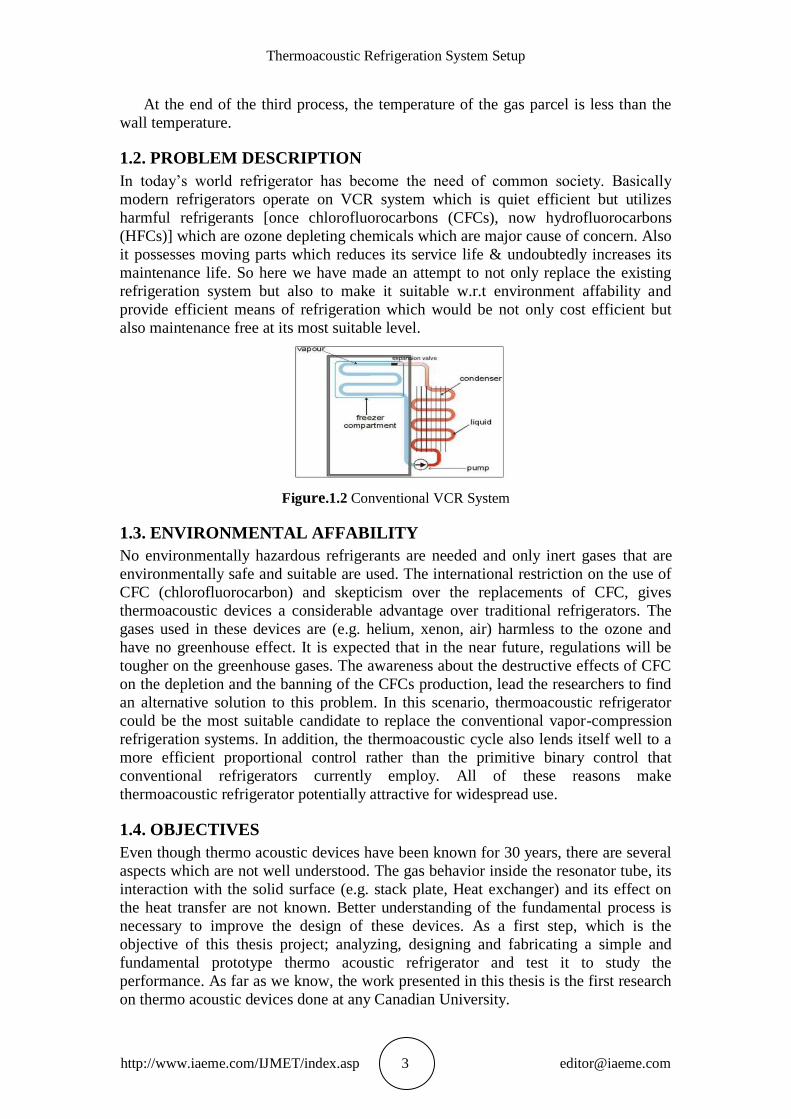
1.2. PROBLEM DESCRIPTION
In today’s world refrigerator has become the need of common society. Basically
modern refrigerators operate on VCR system which is quiet efficient but utilizes
harmful refrigerants [once chlorofluorocarbons (CFCs), now hydrofluorocarbons
(HFCs)] which are ozone depleting chemicals which are major cause of concern. Also
it possesses moving parts which reduces its service life & undoubtedly increases its
maintenance life. So here we have made an attempt to not only replace the existing
refrigeration system but also to make it suitable w.r.t environment affability and
provide efficient means of refrigeration which would be not only cost efficient but
also maintenance free at its most suitable level.
Figure.1.2 Conventional VCR System
1.3. ENVIRONMENTAL AFFABILITY
No environmentally hazardous refrigerants are needed and only inert gases that are
environmentally safe and suitable are used. The international restriction on the use of
CFC (chlorofluorocarbon) and skepticism over the replacements of CFC, gives
thermoacoustic devices a considerable advantage over traditional refrigerators. The
gases used in these devices are (e.g. helium, xenon, air) harmless to the ozone and
have no greenhouse effect. It is expected that in the near future, regulations will be
tougher on the greenhouse gases. The awareness about the destructive effects of CFC
on the depletion and the banning of the CFCs production, lead the researchers to find
an alternative solution to this problem. In this scenario, thermoacoustic refrigerator
could be the most suitable candidate to replace the conventional vapor-compression
refrigeration systems. In addition, the thermoacoustic cycle also lends itself well to a
more efficient proportional control rather than the primitive binary control that
conventional refrigerators currently employ. All of these reasons make
thermoacoustic refrigerator potentially attractive for widespread use.
1.4. OBJECTIVES
Even though thermo acoustic devices have been known for 30 years, there are several
aspects which are not well understood. The gas behavior inside the resonator tube, its
interaction with the solid surface (e.g. stack plate, Heat exchanger) and its effect on
the heat transfer are not known. Better understanding of the fundamental process is
necessary to improve the design of these devices. As a first step, which is the
objective of this thesis project; analyzing, designing and fabricating a simple and
fundamental prototype thermo acoustic refrigerator and test it to study the
performance. As far as we know, the work presented in this thesis is the first research
on thermo acoustic devices done at any Canadian University.

Kaushik S Panara, Amrat M Patel, Nikunj S patel and Jigar D Patel
http://www.iaeme.com/IJMET/index.asp 4 [email protected]
2. DESIGN METHODOLOGY AND IMPLEMENTATION
STRATEGY
2.1. BASIC REFRIGERATION THEORY
The refrigerator is a device that transfers heat from a low –temperature medium to a
higher temperature using external work input. The working fluid used in the
refrigerator is called the refrigerant. The refrigeration process is based on the first and
second law of thermodynamics, and its operation is based on the thermodynamic
refrigeration cycles. The most commonly used refrigeration cycles are the vapour-
compression type.
2.2. VAPOUR-COMPRESSION REFRIGERATION CYCLE
The vapour-compression refrigeration cycle is the most widely used cycle for
refrigerator, air-conditioning systems, and heat pumps. It consists of four
thermodynamic processes, and involves four main components: compressor,
condenser, expansion valve, and evaporator, as shown in Fig.2.1. The refrigerant
enters the compressor as a saturated vapour at a very low temperature and pressure
(state 1). The compression process takes place inside the compressor. Both the
refrigerant becomes superheated vapour at the exit of compressor (state 2). The heat
transfer process takes place in the condenser at a constant pressure, where heat is
transferred from the refrigerant to the high-temperature medium. As a result is a small
decrease in the temperature of the refrigerant as it exits the condenser (state 3). The
four processes of ideal vapour-compression refrigeration cycle are plotted on T-S
diagram in Fig. 2.1.
Figure.2.1 Basic Component of A Refrigeration System Workingon The VCR Cycle.
2.3. ACOUSTICAL THEORY
The understanding of acoustic wave dynamics, i.e. the pressure and velocity fields
created by an acoustic wave, is necessary to understand the working of a thermo
acoustic device. The acoustical theory deals with the study of the longitudinal
acoustic waves. The longitudinal acoustic waves are generated as a result of the
compression, and expansion of the gas medium. The compression of a gas
corresponds to the troughs of a sine wave. An example of how these two relate to
each other is shown in a Fig. 2.3. In a longitudinal wave, the particle displacement is
parallel to the direction of wave propagation i.e., they simply oscillate back and forth
about their respective equilibrium positions. The compression and expansion of a
longitudinal wave result in the variation of pressure along its longitudinal axis of
oscillation. A longitudinal wave requires a material medium such as air or water to
travel. That is, they cannot be generated and/or transmitted in a vacuum. All sound
(acoustic) waves are longitudinal waves and therefore, hold all the properties of the
longitudinal waves discussed above..

Thermoacoustic Refrigeration System Setup
http://www.iaeme.com/IJMET/index.asp 5 [email protected]
2.4. THERMODYNAMIC DESIGN CONSIDERATION & ACTUAL
WORKING
The configuration of standing-wave thermo acoustic refrigerators is simple. A
standing-wave TAR comprises a driver, a resonator, and a stack. The practical device
also utilizes two heat exchangers; however, they are not necessary for creating a
temperature difference across the stack. The parts are assembled as shown in Figure
2.4
Figure 2.4 Schematic Diagram
The driver, which is often a modified electro dynamic loudspeaker, is sealed to a
resonator. Assuming the driver is supplied with the proper frequency input, the
resonator will respond with a standing pressure wave, amplifying the input from the
driver. The standing wave drives a thermo acoustic process within the stack. The
stack is so called because it was first conceived as a stack of parallel plates; however,
the term stack now refers to the thermo acoustic core of a standing-wave TAR no
matter the core’s geometry. The stack is placed within the resonator such that it is
between a pressure antinode and a velocity antinode in the sound wave. Via the
thermo acoustic process, heat is pumped toward the pressure antinode. The overall
device is then a refrigerator or heat pump depending on the attachment of heat
exchangers for practical application. A temperature gradient can be created along the
stack with or without heat exchangers. The exchangers merely allow a useful flow of
heat. If the hot end is thermally anchored to the environment and the cold end
connected to a heat load, the device is then a refrigerator. If the cold side is anchored
to the environment and the load applied at the hot end, the device operates as a heat
pump. In any case, a few simple parts make up the thermo acoustic device, and no
sliding seals are necessary.
Figure 2.5 Behaviour of Gas Molecules
First, the gas parcel undergoes adiabatic compression and travels up the channel
due to the acoustic wave. The pressure increases by twice the acoustic pressure
amplitude, so the temperature of the parcel increases accordingly. At the same time,
the parcel travels a distance that is twice the acoustic displacement amplitude. Then
the second step takes place. When the parcel reaches maximum displacement, it is has
a higher temperature than the adjacent walls, assuming the imposed temperature
gradient is sufficiently small. Therefore, the parcel undergoes an isobaric process by
which it rejects heat to the wall, resulting in a decrease in the size and temperature of
Kaushik S Panara, Amrat M Patel, Nikunj S patel and Jigar D Patel
http://www.iaeme.com/IJMET/index.asp 6 [email protected]
the gas parcel. In the third step, the second half-cycle of the acoustic oscillation
moves the parcel back down the temperature gradient. The parcel adiabatically
expands as the pressure becomes a minimum, reducing the temperature of the gas.
The gas reaches its maximum excursion in the opposite direction with a larger volume
and its lowest temperature.
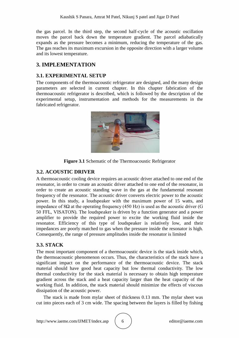
3. IMPLEMENTATION
3.1. EXPERIMENTAL SETUP
The components of the thermoacoustic refrigerator are designed, and the many design
parameters are selected in current chapter. In this chapter fabrication of the
thermoacoustic refrigerator is described, which is followed by the description of the
experimental setup, instrumentation and methods for the measurements in the
fabricated refrigerator.
Figure 3.1 Schematic of the Thermoacoustic Refrigerator
3.2. ACOUSTIC DRIVER
A thermoacoustic cooling device requires an acoustic driver attached to one end of the
resonator, in order to create an acoustic driver attached to one end of the resonator, in
order to create an acoustic standing wave in the gas at the fundamental resonant
frequency of the resonator. The acoustic driver converts electric power to the acoustic
power. In this study, a loudspeaker with the maximum power of 15 watts, and
impedance of 8Ω at the operating frequency (450 Hz) is used as the acoustic driver (G
50 FFL, VISATON). The loudspeaker is driven by a function generator and a power
amplifier to provide the required power to excite the working fluid inside the
resonator. Efficiency of this type of loudspeaker is relatively low, and their
impedances are poorly matched to gas when the pressure inside the resonator is high.
Consequently, the range of pressure amplitudes inside the resonator is limited
3.3. STACK
The most important component of a thermoacoustic device is the stack inside which,
the thermoacoustic phenomenon occurs. Thus, the characteristics of the stack have a
significant impact on the performance of the thermoacoustic device. The stack
material should have good heat capacity but low thermal conductivity. The low
thermal conductivity for the stack material is necessary to obtain high temperature
gradient across the stack and a heat capacity larger than the heat capacity of the
working fluid. In addition, the stack material should minimize the effects of viscous
dissipation of the acoustic power.
The stack is made from mylar sheet of thickness 0.13 mm. The mylar sheet was
cut into pieces each of 3 cm wide. The spacing between the layers is filled by fishing

Thermoacoustic Refrigeration System Setup
http://www.iaeme.com/IJMET/index.asp 7 [email protected]
line spacers (0.36 mm thick) glued onto the surface of the sheet. The mylar sheet is
wound around a 4 mm PVC-rod to obtain a spiral stack as shown in above figure.
3.4. WORKING FLUID
Many parameters such as power, efficiency, and convenience are involved in the
selection of the working fluid, and it depends on the application and objective of the
device.
Thermo acoustic power increases with an increase in the velocity of sound in the
working fluid. The lighter gases such as 2, He, Ne have the higher sound velocity.
Lighter gases are necessary for refrigeration application because heavier gases
condense or freeze at lower temperature, or exhibit non ideal behavior.
3.5. ACOUSTIC RESONATOR
The acoustic resonator is built from a straight acrylic tube of length 70 cm. The
internal diameter of the tube is 6.3 cm and the wall thickness is 6 mm. One end of the
tube has a plate attached to install the speaker frame. At the other end, a movable
piston is placed inside the resonator. The reason for having a movable piston is to
adjust the length of resonator so as to change the fundamental frequency of the
resonator.
3.6. ELECTRONIC DEVICES
An amplifier (MPA-25, Realistic) with the maximum power output of 20 watts is used
to amplify the power input to the loudspeaker to increase power input.
3.7. THERMOCOUPLE
J-type thermocouples is used for the temperature measurements in this study. They
are used to measure the temperature at different locations inside the resonator and the
temperature of heat exchanger fluids. The specifications of the thermocouple are
given below:
Thermocouple grade :- 0 to 150
Limits of Error:-1.0 or 0.75% above 0.
3.8. TEMPERATURE INDICATOR
50 Hz, 200-240V temperature indicator
3.9. PVC CAP SEALINGS & ALUMINIUM END PLUG
PVC pipes are made to contain the speakers, along with threads to make air tight
zones. Aluminium eng plug is placed at the end of the resonator tube to dissipate the
heat generated.
3.10. DESIGN STRATEGY
The stack is considered as the heart of any thermo acoustic system. It can be seen that
these systems have very complicated expressions which cannot be solved, which
necessitates the use of approximations. The coefficient of performance of the stack for
example which can be defined as the ratio of heat pumped by the stack to the acoustic
power dissipated in the stack. A simplified expression is derived from the short stack
and boundary–layer approximation [1]. However, even after the approximation, the

Kaushik S Panara, Amrat M Patel, Nikunj S patel and Jigar D Patel
http://www.iaeme.com/IJMET/index.asp 8 [email protected]
expression looks complicated. They contain a large number of parameters such as
working gas, material and geometrical parameters of the stack. It is difficult to deal
with so many parameters in engineering. However, one can reduce the number of
parameters by choosing a group of dimensionless independent variables. Some
dimensionless parameters can be deduced directly. Others can be defined from the
boundary layer and short stack assumptions [1, 2].
Table 3.2 Operating and Working Gas Variables.
The goal in the design of a thermo acoustic refrigerator is to meet the
requirements of a given cooling power QC and a given low temperature TC. These
requirements are added to the operation parameters. The low temperature TC is
shown indirectly in the form of Temperature gradient ΔTm.
Table 3.3 Normalized Design Parameters.
3.11. DESIGN ASSUMPTION
1. The thermal conduction (i.e. heat leak from cold side to hot side) along both the stack
material and the gas in the stack is neglected.
2. The stack is short compared to the wavelength of the acoustic standing wave.
3. The temperature difference across the stack is a small fraction of the mean
temperature of the stack and gas.
4. The heat and work flow are steady state.
5. The viscosity at the boundary layer is assumed to be zero.
6. The pressure inside the resonator remains almost constant.
Thermoacoustic Refrigeration System Setup
http://www.iaeme.com/IJMET/index.asp 9 [email protected]
3.12. DESIGN PROCEDURE
A total of 5 basic components have to be designed of which stack is the most
important. It is not only the most critical component when it comes to the functioning
of the thermo acoustic refrigerator, but also has a determining effect on the design and
dimensioning of all remaining components. In order to begin with the design of the
stack, first the values of all parameters are obtained and finalized. Sometimes direct
values are not available. Values at particular temperatures are accurately available and
using appropriate formulae, the values at operating temperatures can be calculated.
The temperature gradient
∆TM is indicative of the range of temperatures within which the system is going
to be operating. Given the lowest temperature TC and the highest TH one can obtain
the operating temperature range which is nothing but ∆TM.
∆TM = TH − TC
Assuming that the maximum operating temperature is 45; and minimum -15,
a temperature difference of 60 was obtained. In an effort to simplify calculations a
concentrated effort has been put into converting all parameters into dimensionless
form so that computations are simpler. This is achieved by normalizing them. Hence
∆TM is converted into ∆TMN, the normalized mean temperature difference by
dividing with mean temperature TM. Assuming mean temperature to be 300 K, a
value of 0.2 is obtained.
∆TMN = ∆TM
⁄TM
3.13. DYNAMIC PRESSURE
The dynamic pressure amplitude Po is limited by the following three factors:
1. The maximum force of the driver
2. Non-linearities
3. Drive ratio
The acoustic Mach number ‘M’ can be defined as,
M=PO/ Pm a2
The acoustic Mach number for noble gases has to be limited to 0.1 in order to
avoid any nonlinear effects [1]. Correspondingly, the drive ratio has to be less than
3%. The value of 2% is chosen.
3.14. AVERAGE PRESSURE AND DRIVE RATIO
After fixing the temperatures, the average pressure was calculated. Since the power
density in the thermo acoustic device is proportional to the average mean pressure PM
and drive ratio [PO
⁄Pm]. Hence it is preferable to choose PM and drive ratio D as large
as possible. This is determined by the mechanical strength of the resonator. On the
other hand K, the thermal penetration depth is inversely proportional to the square
root of PM. So a high pressure results in a small K and small stack plate spacing. This
makes the construction difficult. Taking into account these effects and also making
the preliminary choice for Air as the working gas, the maximal pressure is 12 bars and
drive ratio should be D < 3% [2]. An average mean pressure of 10 bars and drive ratio
2% was chosen.
Drive ratio D = 2%
D= [PO
⁄Pm] = 2%= 0.02

Kaushik S Panara, Amrat M Patel, Nikunj S patel and Jigar D Patel
http://www.iaeme.com/IJMET/index.asp 10 [email protected]
Hence PO = 0.2 bar
Hence the maximum dynamic pressure amplitude is limited to Po = 0.2 bar.
3.15. SOUND SPEED
Speed of sound is given by the expression
When a sound wave travels through an ideal gas, the longitudinal wave is expected to
be polytrophic or adiabatic and therefore the pressure and volume obey the
relationship
The association with the sound wave happens so quickly that there is no opportunity
for heat to flow in or out of the volume of air. This is the adiabatic assumption.
Density of gas is
Now,
Therefore speed of sound:
The ideal gas relationship:
Hence,
It can be also written as,
Thermoacoustic Refrigeration System Setup
http://www.iaeme.com/IJMET/index.asp 11 [email protected]
The conditions for these relationships are that the sound propagation process is
adiabatic and the gas obeys the ideal gas laws.
R = 8.314 J/ mol-K and M = 0.004002602 kg/ mol
Hence, for a mean absolute temperature of 300 K the sound speed is found to be a
= 1019.1047 m/s.
3.16. FREQUENCY
As the power in the thermo acoustic device is a linear function of the acoustic
resonance frequency an obvious choice is thus a high resonance frequency. On the
other hand ∆K is inversely proportional to the square root of the frequency which
again implies a stack with very small plate spacing. Making a compromise between
these two effects and the fact that the driver resonance has to be maintained to the
resonator resonance for high efficiency of the driver, the frequency of 238Hz was
chosen [2].
3.17. WORKING GAS
After fixing the above values, it’s time to choose the working gas. It should not be
chemically reactive and should also have a high thermal conductivity. Owing to these
reasons, helium is chosen. It is a noble gas and hence not reactive and has a high
thermal conductivity [3]. It also has the highest sound velocity of all inert gases.
Furthermore helium is cheap in comparison with other noble gases. A gas with a high
thermal conductivity is used since ∆k is proportional to the square root of the thermal
coefficient k. Having chosen Helium, its properties have to be noted down.
Sometimes, accurate values at desired temperatures are not available necessitating the
use of formulae to extrapolate those values to arrive at the values at the required
temperature. Hence the following formulae are used to arrive at accurate values.
Thermal conductivity of helium at required temperature is given by [3].
The value of bk is 0.72 for Helium. At 300K the thermal conductivity is 0.1513
W/m K. The specific heat ratio for a mono-atomic gas like helium is 5/3. Specific heat
is found to be 5192.872 and gas density of helium is 1.626 kg/m3 calculated using the
formula
Prandtl number is a dimensionless parameter characterizing the ratio of
kinematic viscosity to thermal diffusivity, which is a very important parameter to
study the behavior of gases in thermo acoustic devices.
Prandtl number is given by [3]
The Prandtl number written in terms of thermal and viscous penetration depth is [3].

Kaushik S Panara, Amrat M Patel, Nikunj S patel and Jigar D Patel
http://www.iaeme.com/IJMET/index.asp 12 [email protected]
Viscous friction has a negative effect on the performance of a thermo acoustic
system. Decreasing the prandtl number generally increases the performance of a
thermo acoustic device. Kinetic gas theory [4] has shown that the prandtl number for
monatomic gases is about 0.2. Lower prandtl number can be realized using noble
gases like Helium and coefficient of performance of refrigerator can be maximized.
The value of can be obtained from either equation. They yield the same answer.
Prandtl number of 0.6835 is obtained for pure Helium gas.
A value of δv = 0.0987 mm and δv = 0.11941 mm was got by calculations.
3.18. STACK MATERIAL
The formulae of Qcn and Wcn can vary depending on parameters, initial assumptions,
etc. Formulae are subject to improvement over time. All formulae were noted,
analyzed and the best ones were chosen. Some formulae were obtained by theoretical
calculations alone and which may not be validated through experiments/ working
models. Taking these factors into consideration, a comparison of the chosen
parameters with the initial assumptions were made.
The stack forms the heart of the refrigerator where the process of heat pumping
takes place and it is thus an important element which determines the performance of
the refrigerator.
3.19. STACK DESIGN
The stack was designed and normalization of parameters is carried out to aid
simplification. The length and position of the stack can be normalized by /2 . The
thermal and viscous penetration depths can be normalized by the half spacing in the
stack y0. The cold temperature or the temperature difference can be normalized by
TM. Since k and v are related by Prandtl number ‘ ’, this will further simplify the
number of parameters. The acoustic power W and the cooling power QC can be
normalized by the product of the mean pressure PM, the sound velocity ‘a’ and the
cross-sectional area of the stack A[3].PM × A × a
It is also used as a dimensionless parameter for the geometry of the stack. It is takenas
0.75. The thermal and viscous penetration depths are given by [5]

Thermoacoustic Refrigeration System Setup
http://www.iaeme.com/IJMET/index.asp 13 [email protected]
Where, ω = 2πf
Where, k is the thermal conductivity, μ is the viscosity, ρ is the density, Cp is the
isobaric specific heat of the gas, and ω is the angular frequency of the sound wave.
These resultant normalized parameters are given an extra index n. The number of
parameters can once more be reduced by making a choice of some operation
parameters and the working gas. Values for δk and δv were found to be 0.11941 mm
and 0.0987 mm respectively.
3.20. RESULT
The results have shown that the performance of the refrigerator depends on the
working gas, pressure inside the resonator tube, shape of the resonator tube, material,
position and length of the stack. Another merit of this device is that it could provide
cooling and heating simultaneously, that is cooling from the cold-end and heating
from the hot-end. Based on the results of the present investigation the following
conclusions may be drawn:
1. Without the stack the temperature along the resonator tube is almost constant the
variation is within 0.5.
2. Temperature distribution along the resonator is significant effected by the presence of
stack. After nearly 18 minutes of operation a temperature gradient of 7 was
established across the stack.
3. The position of the stack is important in order to get maximum temperature gradient
across the stack.
4. The power input is important to get the maximum temperature gradient across the
stack; therefore an efficient acoustic driver is very important to get better COP
4. FUTURE SCOPE & CONCLUSION
4.1 CONCLUSION
We set out upon this project with the simple goal of constructing a cheap,
demonstrative model of a thermo-acoustic refrigerator. To this end we succeeded: this
experiment proved that thermo-acoustic refrigerators indeed work. Additionally, this
experiment did yield some discoveries regarding the efficiency of thermo-acoustic

Kaushik S Panara, Amrat M Patel, Nikunj S patel and Jigar D Patel
http://www.iaeme.com/IJMET/index.asp 14 [email protected]
refrigeration. It was revealed that finding the optimal frequency is essential for the
maximization of efficiency. This optimal frequency was found using trial-and-error,
because the equation used to calculate frequency was ineffective. Another factor that
increased efficiency was the proper sealing of the apparatus. If the parts are not
properly sealed, heat escapes from the refrigerator, and it does not function as well.
However, the overall efficiency of such an apparatus is debatable. Our research shows
that thermo-acoustic refrigeration has the potential to replace conventional
refrigeration.
4.2 FUTURE SCOPE
The use of inexpensive, household items to construct the refrigerators could explain
such low efficiency. If other materials were used, it is possible that the factor that
could be adjusted for optimization. The stack works best when it is centered on a
region in the tube where the standing wave produces the highest pressure (and
thermal) forces. Experimenting with different frequencies and stack placements could
yield greater efficiency. We also concluded that the shape and length of the resonator
tube was a major factor in the efficiency of the device. Improvements to the resonator
tube would involve further research into the effects that differently shaped tubes
would have on the thermo-acoustic effect. Perhaps a resonator tube which was tapered
to focus the intensity of the wave and therefore increase both the pressure and
temperature maximum would increase effectiveness. However, as stated above further
research is required to ascertain the resonator tube shape of maximum efficiency.
Other tube factors that should be explored include tube diameter and length. Due to
the correlation between the resonator tube and the frequency used these two factors
would have to be experimented with simultaneously. If peak efficiency was to be
achieved, the most optimal solution would be to model the acoustic properties by
computer simulation and predict efficient tube-frequency combinations in that
manner.
REFERENCES
[1] Mattew. E. Poese & Steven. L.Garrett “Performance measurement of thermo
acoustic refrigerator.” Journal of the Acoustical Society of America, June 2008.
[2] Richard raspet & Henry. E. Bass “Element interaction in thermo acoustic heat
engine.”International Journal of Thermal Science, Nov 2003.
[3] Nathan thoman weiland, Ben. T. Zinn “Design of thermo acoustic engine in
internal combustion”, March 2003.
[4] D.A.Geller & W.A.Swift “Thermoacoustic enrichment of isotopes of neon.” Jan
2004.
[5] Mark. P. Telez “Design and Testing of thermoacoustic power converter.” May
2006.
[6] Byram Arman, John Henry Royal “thermoacoustic cogeneration system.”
Applied Acoustics, Aug 2003.
[7] Bryan .O. Maqury & Steve .M. Cole “thermoacoustic upset-butt welding
process.”May 2012.
[8] Barton .L. Smith “Thermoacoustic cooling device.” Fifth Edition, McGraw-Hill,
New York, Sep 2007.
[9] Michel .D. Newman & Stephen .A. Macormick “Crogenic Heat exchanger for
thermo acoustic refrigeration system.”Jun 2011.
Thermoacoustic Refrigeration System Setup
http://www.iaeme.com/IJMET/index.asp 15 [email protected]
[10] Orest .G. symko and Young .S. Kwon” Compact thermo acoustic array energy
generator.” Aug 2011
[11] Garrett S.T., Adeff J.A., and Hofler T.J. “Thermoacoustic refrigerator for space
applications.” Journal of thermoacoustic and heat Transfer, 7(4): 595-599, 1993.
[12] Tijani M.E.H., Zeegers J.C.H., and De Waele A.T.A.M. “Construction and
performance of a Thermoacoustic refrigerator.” Cryogenics, 42(1): 59-66, 2001.
[13] Sakamoto S. “The experimental studies of thermoacoustic cooler.” Ultrasonics,
42(1):53-56, 2004.
[14] Wetzel M, and Herman C. “Experimental study of thermoacoustic effects on a
single plate part 2: heat transfer.” Heat and Mass Transfer, 35(6): 433-441.
[15] Mr. Parthiban Kas. Simulation of Thermodynamic Analysis of Cascade
Refrigeration System with Alternative Refrigerants, International Journal of
Mechanical Engineering and Technology, 6(1), 2015, pp. 71 – 91.
[16] Tejshree Bornare, Abhishek Badgujar and Prathamesh Natu. Vortex Tube
Refrigeration System Based on Compressed Air, International Journal of
Mechanical Engineering and Technology, 6(7), 2015, pp. 99 – 104.
[17] Peethambaran K M, Asok Kumar N and John T D. Adsorption Refrigeration
System For Automobiles An Experimental Approach, International Journal of
Mechanical Engineering and Technology, 5(2), 2014, pp. 122 - 132.