services architecture v3.2 student guide download
DESCRIPTION
Curso Arquitectura ALCATELTRANSCRIPT
7/21/2019 Services Architecture v3.2 Student Guide Download
http://slidepdf.com/reader/full/services-architecture-v32-student-guide-download 1/429
Alcatel-Lucent Services Architecture v3.2 Module 0 – Page 1
Alcatel-Lucent Services Architecture
Module 0 — Course Introduction
All rights reserved © 2012 Alcatel-Lucent
7/21/2019 Services Architecture v3.2 Student Guide Download
http://slidepdf.com/reader/full/services-architecture-v32-student-guide-download 2/429
Alcatel-Lucent Services Architecture v3.2 Module 0 – Page 2
Alcatel-Lucent Services Architecture v3.2 Module 0 | 2 All r ights reserved © 2012 Alcatel-Lucent
Module Overview
Alcatel-Lucent Career Certification
General Course Information
Timeline
Objectives
Prerequisites
Introduction
Goal
Administration
Alcatel-Lucent Services Architecture
This course is part of the Alcatel-Lucent Service Routing Certification (SRC) Program. See www.alcatel-
lucent.com/src for more information on the SRC program.
To locate additional information relating to the topics presented in this manual, refer to the following:
Technical Practices for the specific product
Internet Standards documentation such as protocol standards bodies, RFCs, and IETF drafts
Technical support pages of the Alcatel-Lucent website located at: http://www.alcatel-lucent.com/support
All rights reserved © 2012 Alcatel-Lucent

7/21/2019 Services Architecture v3.2 Student Guide Download
http://slidepdf.com/reader/full/services-architecture-v32-student-guide-download 3/429
Alcatel-Lucent Services Architecture v3.2 Module 0 – Page 3
Alcatel-Lucent Services Architecture v3.2 Module 0 | 3 All r ights reserved © 2012 Alcatel-Lucent
Alcatel-Lucent Service Routing Certification Program ― Four Certifications
ALCATEL-LUCENT
NETWORK ROUTING SPECIALIST I4 DAYS / 1 COURSE / 1 WRITTEN EXAM
ALCATEL-LUCENT
SERVICE ROUTING ARCHITECT49 DAYS / 11 COURSES / 11 WRITTEN EXAMS / 2 PRACTICAL LAB EXAMS
ALCATEL-LUCENT
NETWORK ROUTING SPECIALIST II18 DAYS / 4 COURSES / 4 WRITTEN EXAMS /
1 PRACTICAL LAB EXAM
ALCATEL-LUCENT
TRIPLE PLAY ROUTING PROFESSIONAL36 DAYS / 8 COURSES / 8 WRITTEN EXAMS /1 PRACTICAL LAB EXAM
ALCATEL-LUCENT
MOBILE ROUTING PROFESSIONAL32 DAYS/ 7 COURSES / 7 WRITTEN EXAMS /2 PRACTICAL LAB EXAMS
All rights reserved © 2012 Alcatel-Lucent
7/21/2019 Services Architecture v3.2 Student Guide Download
http://slidepdf.com/reader/full/services-architecture-v32-student-guide-download 4/429
Alcatel-Lucent Services Architecture v3.2 Module 0 – Page 4
Alcatel-Lucent Services Architecture v3.2 Module 0 | 4 All r ights reserved © 2012 Alcatel-Lucent
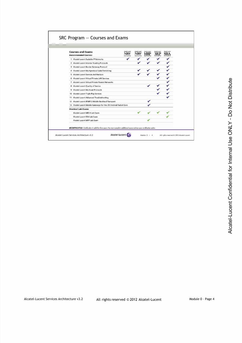
SRC Program ― Courses and Exams
All rights reserved © 2012 Alcatel-Lucent

7/21/2019 Services Architecture v3.2 Student Guide Download
http://slidepdf.com/reader/full/services-architecture-v32-student-guide-download 5/429
Alcatel-Lucent Services Architecture v3.2 Module 0 – Page 5
Alcatel-Lucent Services Architecture v3.2 Module 0 | 5 All r ights reserved © 2012 Alcatel-Lucent
SRC Program ― Exam Profile
Exam Name Exam NumberExam Pre-requisites
(4A0-XXX)
Alcatel-Lucent Scalable IP Networks 4A0-100 NA
Alcatel-Lucent Interior Routing Protocols 4A0-101 NA
Alcatel-Lucent Border Gateway Protocol 4A0-102 NA
Alcatel-Lucent Multiprotocol Label Switching 4A0-103 NA
Alcatel-Lucent Services Architecture 4A0-104 NA
Alcatel-Lucent Virtual Private LAN Services 4A0-105 NA
Alcatel-Lucent Virtual Private Routed Networks 4A0-106 NA
Alcatel-Lucent Quality of Service 4A0-107 NA
Alcatel-Lucent Multicast Protocols 4A0-108 NA
Alcatel-Lucent Triple Play Services 4A0-109 NA
Alcatel-Lucent Advanced Troubleshooting 4A0-110 NA
Alcatel-Lucent IP/MPLS Mobile Backhaul Transport 4A0-M01 NA
Alcatel-Lucent Mobile Gateways for the LTE Evolved
Packet Core4A0-M02 NA
Alcatel-Lucent Network Routing Specialist II Lab Exam NRSII4A0 100, 101, 103, 104
Al catel- Lucent Mobile Routing Profess ional Lab Exam MRP4A0 100, 101, 103, 104, 107, M01, M02, NRSII4A0
Alcatel -Lucent Serv ice Routing Archi tect Lab Exam ASRA4A0100, 101, 102, 103, 104, 105, 106, 107, 108, 109, 110,
NRSII4A0
All rights reserved © 2012 Alcatel-Lucent

7/21/2019 Services Architecture v3.2 Student Guide Download
http://slidepdf.com/reader/full/services-architecture-v32-student-guide-download 6/429
Alcatel-Lucent Services Architecture v3.2 Module 0 – Page 6
Alcatel-Lucent Services Architecture v3.2 Module 0 | 6 All r ights reserved © 2012 Alcatel-Lucent
Exam Delivery
Written Exams
Delivered by Prometric
Global provider of testing services
5000+ test sites worldwide
Register at:www.prometric.com/alcatel-lucent
Lab Exams
Written at Alcatel-Lucent sites
NRS II Certification
• Half-day lab exam
SRA Certification
• Full-day lab exam
All rights reserved © 2012 Alcatel-Lucent

7/21/2019 Services Architecture v3.2 Student Guide Download
http://slidepdf.com/reader/full/services-architecture-v32-student-guide-download 7/429
Alcatel-Lucent Services Architecture v3.2 Module 0 – Page 7
Alcatel-Lucent Services Architecture v3.2 Module 0 | 7 All r ights reserved © 2012 Alcatel-Lucent
SRC Program Global Reach, Flexible Delivery Options
On-site delivery at your business location anywhere in the world
Delivery from any of fifteen Alcatel-Lucent University locations globally APAC
―Shanghai, China
― Sydney, Australia
― Melbourne, Australia
― Wellington, New Zealand
― Bangalore, Chennai, Gurgaon, Mumbai, India
Europe
― Antwerp, Belgium
― Newport, UK
― Paris, France
Americas
― Plano, USA
―Ottawa, Canada
―Mexico City, Mexico
― Sao Paulo, Brazil
Class schedules posted @ www.alcatel-lucent.com/src
Registration online @ www.alcatel-lucent.com/srcreg
All rights reserved © 2012 Alcatel-Lucent

7/21/2019 Services Architecture v3.2 Student Guide Download
http://slidepdf.com/reader/full/services-architecture-v32-student-guide-download 8/429
Alcatel-Lucent Services Architecture v3.2 Module 0 – Page 8
Alcatel-Lucent Services Architecture v3.2 Module 0 | 8 All r ights reserved © 2012 Alcatel-Lucent
Your Own Service Router Lab – Now you can have one
Need access to a lab to help you:
Prepare for your NRS II and SRA exams?
Practice and build your service routing knowledge and configurationskills?
The Alcatel-Lucent Exam Preparation service provides:
Remote, private access (7×24) to an Alcatel-Lucent service router lab:
six-node fully meshed network – three-hour time slots available
Access to a suite of over 30 lab “practice” scenarios with optimal
solutions
Access to traffic simulation and analysis tools
To find out more and sign up visit http://www.alcatel-
lucent.com/src/examprep
All rights reserved © 2012 Alcatel-Lucent

7/21/2019 Services Architecture v3.2 Student Guide Download
http://slidepdf.com/reader/full/services-architecture-v32-student-guide-download 9/429
Alcatel-Lucent Services Architecture v3.2 Module 0 – Page 9
Alcatel-Lucent Services Architecture v3.2 Module 0 | 9 All r ights reserved © 2012 Alcatel-Lucent
Credit for Other IP Certifications
Cisco or Juniper certified?
You can receive exemptions fromsome of the SRC exams, if you
hold any one of the Cisco or
Juniper certifications identified
Certifications must be valid to
receive exemptions
Submit your request for
exemptions at: http://www.alcatel-
lucent.com/srcexemptions
All rights reserved © 2012 Alcatel-Lucent

7/21/2019 Services Architecture v3.2 Student Guide Download
http://slidepdf.com/reader/full/services-architecture-v32-student-guide-download 10/429
Alcatel-Lucent Services Architecture v3.2 Module 0 – Page 10
Alcatel-Lucent Services Architecture v3.2 Module 0 | 10 All r ights reserved © 2012 Alcatel-Lucent
Alcatel-Lucent Services Architecture ― Goal
This course will provide course participants with foundation
knowledge of Layer 2 services (VPWS and VPLS), Layer 3
services (IES and VPRN), and mirroring service and how to
implement these services in an Alcatel-Lucent environment.
All rights reserved © 2012 Alcatel-Lucent
7/21/2019 Services Architecture v3.2 Student Guide Download
http://slidepdf.com/reader/full/services-architecture-v32-student-guide-download 11/429
Alcatel-Lucent Services Architecture v3.2 Module 0 – Page 11
Alcatel-Lucent Services Architecture v3.2 Module 0 | 11 All r ights reserved © 2012 Alcatel-Lucent
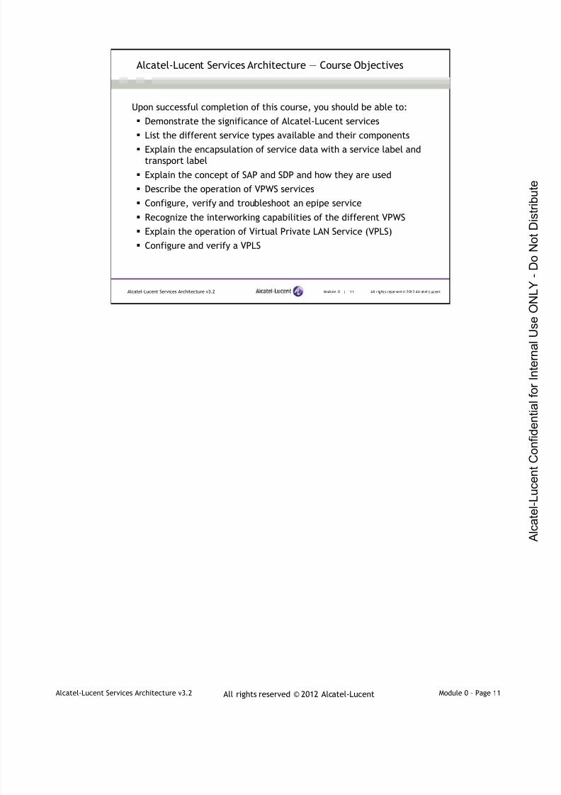
Alcatel-Lucent Services Architecture ― Course Objectives
Upon successful completion of this course, you should be able to:
Demonstrate the significance of Alcatel-Lucent services
List the different service types available and their components Explain the encapsulation of service data with a service label and
transport label
Explain the concept of SAP and SDP and how they are used
Describe the operation of VPWS services
Configure, verify and troubleshoot an epipe service
Recognize the interworking capabilities of the different VPWS
Explain the operation of Virtual Private LAN Service (VPLS)
Configure and verify a VPLS
All rights reserved © 2012 Alcatel-Lucent
7/21/2019 Services Architecture v3.2 Student Guide Download
http://slidepdf.com/reader/full/services-architecture-v32-student-guide-download 12/429
Alcatel-Lucent Services Architecture v3.2 Module 0 – Page 12
Alcatel-Lucent Services Architecture v3.2 Module 0 | 12 All r ights reserved © 2012 Alcatel-Lucent
Alcatel-Lucent Services Architecture ― Course Objectives
Upon successful completion of this course, you should be able to:
Use the correct operations, administration and maintenance (OAM)
tools to analyze, manage, and troubleshoot IP/MPLS service
networks
Describe mirror services and differentiate between local and
distributed mirror services
Explain the operation of Internet enhanced services (IES)
Describe the operation of the basic VPRN architecture
Configure, verify, and troubleshoot an IPv4 VPRN
Configure, verify, and troubleshoot an IPv6 VPRN
All rights reserved © 2012 Alcatel-Lucent
7/21/2019 Services Architecture v3.2 Student Guide Download
http://slidepdf.com/reader/full/services-architecture-v32-student-guide-download 13/429
Alcatel-Lucent Services Architecture v3.2 Module 0 – Page 13
Alcatel-Lucent Services Architecture v3.2 Module 0 | 13 All r ights reserved © 2012 Alcatel-Lucent
Alcatel-Lucent Services Architecture ― Course Timeline
Day 1
Module 0 — Course Introduction
Module 1 — Services Overview and Implementation Module 2 — Virtual Private Wire Service – section 1
Lab 1 – IP/MPLS Infrastructure
Lab 2 - Distributed Epipe Service
Day 2
Module 2 — Virtual Private Wire Service – section 2 and 3
Module 3 — Virtual Private LAN Service
Lab 3 – VPLS Service
Lab 4 – Spoke Termination to a VPLS
All rights reserved © 2012 Alcatel-Lucent
7/21/2019 Services Architecture v3.2 Student Guide Download
http://slidepdf.com/reader/full/services-architecture-v32-student-guide-download 14/429
Alcatel-Lucent Services Architecture v3.2 Module 0 – Page 14
Alcatel-Lucent Services Architecture v3.2 Module 0 | 14 All r ights reserved © 2012 Alcatel-Lucent
Alcatel-Lucent Services Architecture ― Course Timeline (cont’d)
Day 3
Module 4 — OAM Tools and Mirroring Service
Lab 5 — OAM Tools Lab 6 — Mirror Service
Module 5 — Layer 3 Services (Sections 1 and 2)
Lab 7 — IES
Lab 8 — VPLS Spoke Termination on IES
Day 4
Module 5 — Layer 3 Services (Sections 3-6)
Lab 9 — IPv4 VPRN
Lab 10 — IPv6 VPRN
All rights reserved © 2012 Alcatel-Lucent

7/21/2019 Services Architecture v3.2 Student Guide Download
http://slidepdf.com/reader/full/services-architecture-v32-student-guide-download 15/429
Alcatel-Lucent Services Architecture v3.2 Module 0 – Page 15
Alcatel-Lucent Services Architecture v3.2 Module 0 | 15 All r ights reserved © 2012 Alcatel-Lucent
Alcatel-Lucent Services Architecture ― Course Prerequisites
Suggested Prerequisites
Alcatel-Lucent Scalable IP Networks
Alcatel-Lucent Interior Routing Protocols Alcatel-Lucent Multiprotocol Label Switching
Alcatel-Lucent Services Architecture Exam
To ensure full comprehension of the material covered in this course, it is
recommended that, upon successful completion of the Services Architecture
course, the student register for and take this exam.
Notice that the BGP section of the ASIN course is one of the important topics required as a prerequisite for
the Virtual Private Routed Network sections of module 5.
All rights reserved © 2012 Alcatel-Lucent

7/21/2019 Services Architecture v3.2 Student Guide Download
http://slidepdf.com/reader/full/services-architecture-v32-student-guide-download 16/429
Alcatel-Lucent Services Architecture v3.2 Module 0 – Page 16
Alcatel-Lucent Services Architecture v3.2 Module 0 | 16 All r ights reserved © 2012 Alcatel-Lucent
Alcatel-Lucent Services Architecture ― Symbols and Icons
IP router Network cloud
(various colors)Alcatel-Lucent 7750 SR
Customer sites MP-BGP Update
Generic switch
Internet
Encapsulated Ethernet FramePipe
All rights reserved © 2012 Alcatel-Lucent

7/21/2019 Services Architecture v3.2 Student Guide Download
http://slidepdf.com/reader/full/services-architecture-v32-student-guide-download 17/429
Alcatel-Lucent Services Architecture v3.2 Module 0 – Page 17
Alcatel-Lucent Services Architecture v3.2 Module 0 | 17 All r ights reserved © 2012 Alcatel-Lucent
Administration
Registration
Facility information
Restrooms
Communications
Materials
Schedule
Introductions
Name and company
Experience
Familiarity with Services Architecture
Questions
All rights reserved © 2012 Alcatel-Lucent

7/21/2019 Services Architecture v3.2 Student Guide Download
http://slidepdf.com/reader/full/services-architecture-v32-student-guide-download 18/429
www.alcatel-lucent.com
3HE-02770-AAAA-WBZZA Edition 01

7/21/2019 Services Architecture v3.2 Student Guide Download
http://slidepdf.com/reader/full/services-architecture-v32-student-guide-download 19/429
Alcatel-Lucent Services Architecture v3.2 Module 1 – Page 1All rights reserved © 2012 Alcatel-Lucent
Alcatel-Lucent Services Architecture
Module 1 — Services Overview & Implementation

7/21/2019 Services Architecture v3.2 Student Guide Download
http://slidepdf.com/reader/full/services-architecture-v32-student-guide-download 20/429
Alcatel-Lucent Services Architecture v3.2 Module 1 – Page 2All rights reserved © 2012 Alcatel-Lucent
Module 1 | 2 All rights reserved © 2012 Alcatel-LucentAlcatel-Lucent Services Architecture v 3.2
Module Objectives
After successfully completing this module, you will be able to:
Describe a service router and how it differs from a traditionalrouter
Describe the different service types offered on the Alcatel-
Lucent 7750 SR
Explain the components required to support these services
Alcatel-Lucent Services Archi tecture
This course is part of the Alcatel-Lucent Service Routing Certification (SRC) Program. Visit the Alcatel-Lucent web site at www.alcatel-lucent.com/src for more information on the SRC program.
To locate additional information related to the topics presented in this manual, refer to the following:
Technical Practices for the specific product
Internet Standards documentation such as protocol standards bodies, RFCs and IETF drafts
Technical support pages of the Alcatel-Lucent web site located at http://www.alcatel-lucent.com/support
This module provides an introduction to the concept of a service router; the service configuration modelwill be described along with various service entities such as customer, SAP and SDP. In addition, a briefoverview of service policies will also be covered. We will also examine how Alcatel-Lucent implements theservices concept, and steps are provided for deploying a services tunnel in a service provider’s coreMPLS backbone.

7/21/2019 Services Architecture v3.2 Student Guide Download
http://slidepdf.com/reader/full/services-architecture-v32-student-guide-download 21/429
Alcatel-Lucent Services Architecture v3.2 Module 1 – Page 3All rights reserved © 2012 Alcatel-Lucent
Services Overview & Implementation
Section 1 — Introduction to Services

7/21/2019 Services Architecture v3.2 Student Guide Download
http://slidepdf.com/reader/full/services-architecture-v32-student-guide-download 22/429
Alcatel-Lucent Services Architecture v3.2 Module 1 – Page 4All rights reserved © 2012 Alcatel-Lucent
Module 1 | 4 All rights reserved © 2012 Alcatel-LucentAlcatel-Lucent Services Architecture v 3.2
Section Objectives
After successfully completing this section, you will be able to:
Describe the features of a service router
List the differences between a service router and a traditionalrouter
Define the concept of a “service”
Describe the types of services offered by the Alcatel-Lucent service
router
7/21/2019 Services Architecture v3.2 Student Guide Download
http://slidepdf.com/reader/full/services-architecture-v32-student-guide-download 23/429
Alcatel-Lucent Services Architecture v3.2 Module 1 – Page 5All rights reserved © 2012 Alcatel-Lucent
Module 1 | 5 All rights reserved © 2012 Alcatel-LucentAlcatel-Lucent Services Architecture v 3.2
Telecommunication Services Technologies
Service Providers Telecommunications Networks
Time division multiplexing (TDM) technologies for real-time voice
Frame Relay and ATM for private network services with specificservice levels
IP for best effort data services
Requirement is to offer all types of services on one platform
Historically, telecommunications service providers have deployed completely separate networks toprovide different types of services, such as time division multiplexing (TDM) technologies for real-timevoice, Frame Relay and ATM for private network services with specific service levels and IP for best effortdata services.
7/21/2019 Services Architecture v3.2 Student Guide Download
http://slidepdf.com/reader/full/services-architecture-v32-student-guide-download 24/429
Alcatel-Lucent Services Architecture v3.2 Module 1 – Page 6All rights reserved © 2012 Alcatel-Lucent
Module 1 | 6 All rights reserved © 2012 Alcatel-LucentAlcatel-Lucent Services Architecture v 3.2
Converged Network Infrastructure Requirements
Service providers consolidate the delivery of multiple service typesonto a single networking technology because of:
High cost of maintaining and operating discrete legacy networks
The need to continue to support the high revenue legacy servicessuch as Frame Relay and TDM
Consumer demand for new services that require higher bandwidth
service at decreasing prices
A number of factors are driving service providers to evolve to a single network infrastructure that supportsthe delivery of a wide variety of telecommunications services. These include:
•High cost of maintaining and operating discrete legacy networks.
•Service provider desire to continue to support high-revenue legacy services such as Frame Relay andTDM.
•Consumer demand for new services such as wireless data and streaming video.•Competitive market creating consumer expectations of higher bandwidth service at decreasing prices.
One approach to building a common infrastructure for deploying a wide range of telecommunicationservices uses a core IP/MPLS network that supports a range of virtual private network (VPN) services.

7/21/2019 Services Architecture v3.2 Student Guide Download
http://slidepdf.com/reader/full/services-architecture-v32-student-guide-download 25/429
Alcatel-Lucent Services Architecture v3.2 Module 1 – Page 7All rights reserved © 2012 Alcatel-Lucent
Module 1 | 7 All rights reserved © 2012 Alcatel-LucentAlcatel-Lucent Services Architecture v 3.2
Alcatel-Lucent Solution: Alcatel-Lucent 7750 Service Router
A single network infrastructure using a core IP/MPLS network that supports a
range of virtual private network (VPN) services
The Alcatel-Lucent 7750 SR product family was specifically designed to build a single networkinfrastructure using a core IP/MPLS network that supports a range of virtual private network (VPN)services
The Alcatel-Lucent 7750 SR has the ability to collapse separate overlay networks onto one platform whilestill supporting an overlay model. Before we get into the details of the Alcatel-Lucent Service Router, weneed to understand what is meant by virtual private network (VPN)
7/21/2019 Services Architecture v3.2 Student Guide Download
http://slidepdf.com/reader/full/services-architecture-v32-student-guide-download 26/429
Alcatel-Lucent Services Architecture v3.2 Module 1 – Page 8All rights reserved © 2012 Alcatel-Lucent
Module 1 | 8 All rights reserved © 2012 Alcatel-LucentAlcatel-Lucent Services Architecture v 3.2
Virtual Private Network (VPN) Service
VPN is a network in which a shared infrastructure is used to provide private
services to its users
Virtual - A VPN to the service provider is a virtual network
Private - A VPN to the customer is a private network
Network – A collection of devices that communicate with each other
Service:
A logical entity that refers to a type of connectivity (Internet, Layer 2 or
Layer 3 VPN)
Each service is uniquely identified by a service ID
VPN is a network in which a service provider shared infrastructure is used to provide private services to itscustomers. It is virtual since it does not require separate dedicated circuits between various locations, andit is based on the logical as opposed to physical separation of the facilities. It is private in the sense thatcustomers can maintain their own addressing and routing schemes fully independent of and transparent toother customers.
A service is a logical globally unique entity that provides a uniform, end-to-end configuration,
management, and billing model for provisioning either Internet or VPN connectivity between customeraccess points; it can be either local or distributed.

7/21/2019 Services Architecture v3.2 Student Guide Download
http://slidepdf.com/reader/full/services-architecture-v32-student-guide-download 27/429
Alcatel-Lucent Services Architecture v3.2 Module 1 – Page 9All rights reserved © 2012 Alcatel-Lucent
Module 1 | 9 All rights reserved © 2012 Alcatel-LucentAlcatel-Lucent Services Architecture v 3.2
The Alcatel-Lucent Service Router
A scalable IP router that offers best-effort IP routing and supports data
services using a service-oriented architecture
A service router is a scalable Internet router that offers best-effort Internet services as well as enables themigration of traditional data services to a service-oriented architecture.
Existing Layer 3 switches and Internet routers were designed around interfaces or physical ports for best-effort packet forwarding. It is often the case that edge routers are old core/Internet routers withchannelized interfaces; traditional IP service platforms were designed for low-speed, best-effort consumerservices.
Alternately, the Alcatel-Lucent service router is designed primarily for use as a service router. The servicerouter delivers service-level-agreement-based services, also known as SLA-based services. A servicerouter such as the 7750 SR must support additional functionality including:
Quality of Service (QoS) - The ability to provide distinct levels of service depending on the customer,application or service level agreement.
Accounting - The ability to measure the traffic and service delivered based on a specific customer orservice and perform logging and billing accordingly
Filtering — The ability to restrict or monitor specific traffic, based on customer or service
Troubleshooting — The ability to analyze and troubleshoot problems from the perspective of a specificservice
These capabilities are supported to a varying degree in traditional IP routers, but generally they areoriented around the router’s interfaces or physical ports. It can be difficult to apply these functions to aspecific service instance since many services may use the same port.

7/21/2019 Services Architecture v3.2 Student Guide Download
http://slidepdf.com/reader/full/services-architecture-v32-student-guide-download 28/429
Alcatel-Lucent Services Architecture v3.2 Module 1 – Page 10All rights reserved © 2012 Alcatel-Lucent
Module 1 | 10 All rights reserved ©2012 Alcatel-LucentAlcatel-Lucent Services Architecture v 3.2
Typical IP/MPLS Service Network Components
A service router functions as the Provider Edge (PE) router in a
service network
A PE router provides the interface between the customer networkand the core service provider network
The key component in a service network is the provider edge (PE) router that provides the interfacebetween the customer network and the core service provider network. All the service-specific functions arefound in the PE router
The service router functions as the PE router in a service network. It is a scalable, full function IP/MPLSrouter that supports the full range of service types and customers and the additional service managementcapabilities described earlier.
Access Routers typically support low-speed Internet access services and are not equipped to provide thehigher bandwidth required to meet future customer needs.
Core or Provider (P) routers support high-speed interfaces and are primarily designed to provide thecapacities for forwarding large quantities of data. Core routers are not well-suited for supporting the QoS,bandwidth management and accounting functions needed by a service-edge router. These devices can beconnected to other PE or P routers. They will run a routing protocol for the purposes of internal routing inthe provider core using the provider’s choice of IP addressing.
Layer 2 or IP Service Switches were created in an attempt to enhance core routers; by increasing theprocessing power, IP service switches provide services such as subscriber management and encryption.However, the IP service switch does not support complete Internet routing functionality, nor does it providethe same variety of routing policies that are available in a service edge router.
7/21/2019 Services Architecture v3.2 Student Guide Download
http://slidepdf.com/reader/full/services-architecture-v32-student-guide-download 29/429
Alcatel-Lucent Services Architecture v3.2 Module 1 – Page 11All rights reserved © 2012 Alcatel-Lucent
Module 1 | 11 All rights reserved ©2012 Alcatel-LucentAlcatel-Lucent Services Architecture v 3.2
Alcatel-Lucent 7750 SR Service Types
The following types of service are offered on the Alcatel-Lucent 7750
SR:
VPN services
Virtual private wire service (VPWS) — provides a point-to-pointservice that emulates a leased line
Virtual private LAN service (VPLS) — provides a multipoint Ethernetservice similar to an Ethernet switch
Virtual private routed network service (VPRN) — provides amultipoint IP routed service
Internet Enhanced Service (IES)
Provides the customer with a Layer 3 IP interface to send andreceive Internet traffic
Mirroring services
A variety of different service types are supported in a service network of Alcatel-Lucent 7750 SRs, basedon a common core of IP/MPLS technology. The different possible VPN services are:
Virtual Private Wire Service (VPWS) also known as Virtual Leased Lines (VLL)– Layer 2 point-to-pointservice.
Virtual Private LAN Service (VPLS) - Layer 2 multipoint-to-multipoint VPN
Virtual Private Routed Network (VPRN) - Layer 3 IP multipoint-to-multipoint VPN service as defined inRFC 4364 (formerly RFC 2547bis)
In addition to the VPN based services, the 7750 SR supports the Internet Enhanced Service. IES is aLayer 3 direct Internet access service where the customer is assigned an IP interface for Internetconnectivity.
Mirroring services - allows an operator to see the actual traffic on a customer’s service with a sniffer.Mirror service be will be discussed later in module 4.

7/21/2019 Services Architecture v3.2 Student Guide Download
http://slidepdf.com/reader/full/services-architecture-v32-student-guide-download 30/429
Alcatel-Lucent Services Architecture v3.2 Module 1 – Page 12All rights reserved © 2012 Alcatel-Lucent
Module 1 | 12 All rights reserved ©2012 Alcatel-LucentAlcatel-Lucent Services Architecture v 3.2
Virtual Private Wire Service (VPWS)
VPWS is a Layer 2 point-to-point service
VPWS defines a virtual point-to-point service that emulates a private leased
line connection
VPWS encapsulates customer data and transports it across the service
provider’s network in a GRE (generic routing encapsulation) or MPLS tunnel
Virtual Private Wire Service (VPWS)
The Alcatel-Lucent 7750 SR supports a Layer 2 point-to-point service commonly known as a VirtualPrivate Wire Service (VPWS). The VPWS encapsulates customer data and transports it across a serviceprovider’s IP or MPLS network in a GRE or MPLS tunnel. VPWS is sometimes referred to as Layer 1VPN, since there is no MAC learning required.
The Alcatel-Lucent service router is able to provide point-to-point Ethernet, Frame Relay, ATM
(Asynchronous Transfer Mode) or TDM (Time Division Multiplexing) service. In the slide figure a serviceprovider network provides an epipe (point-to-point Ethernet) service.
A pseudowire is an emulated, Layer 2 circuit built across an MPLS network that can transport Layer 2PDUs (protocol data units) as if they were transmitted on their native media. Epipes (Ethernet), apipes(ATM), fpipes (Frame Relay), ipipes (IP Interworking) and cpipes (TDM circuit emulation) are all examplesof pseudowire technologies and are described in more detail in Module 2.
7/21/2019 Services Architecture v3.2 Student Guide Download
http://slidepdf.com/reader/full/services-architecture-v32-student-guide-download 31/429
Alcatel-Lucent Services Architecture v3.2 Module 1 – Page 13All rights reserved © 2012 Alcatel-Lucent
Module 1 | 13 All rights reserved ©2012 Alcatel-LucentAlcatel-Lucent Services Architecture v 3.2
Types of VPWS
VPWS service supported on the Alcatel-Lucent 7750 SR
EPipe - emulates a point-to-point Ethernet service
Apipe - emulates a point-to-point ATM service
Fpipe - emulates a point-to-point Frame Relay circuit
Cpipe - emulates a point-to-point TDM circuit
Ipipe - provides IP interworking capabilities between different Layer 2 technologies
The types of VPWS service supported on the Alcatel-Lucent 7750 SR include:
Epipe - emulates a point-to-point Ethernet service. VLAN tagged Ethernet frames are supported.Interworking with other Layer 2 technologies is also supported.
Apipe - emulates a point-to-point ATM service. A number of sub-types are provided to support different ATM service types.
Fpipe - emulates a point-to-point Frame Relay circuit. Some features for interworking with ATM are alsosupported.
Cpipe - emulates a point-to-point TDM circuit.
Ipipe - provides IP interworking capabilities between different Layer 2 technologies

7/21/2019 Services Architecture v3.2 Student Guide Download
http://slidepdf.com/reader/full/services-architecture-v32-student-guide-download 32/429
Alcatel-Lucent Services Architecture v3.2 Module 1 – Page 14All rights reserved © 2012 Alcatel-Lucent
Module 1 | 14 All rights reserved ©2012 Alcatel-LucentAlcatel-Lucent Services Architecture v 3.2
VPWS Advantages
Customer’s perspective:
Supports ATM, Frame Relay, TDM or Ethernet
Service provider (SP) network appears as a leased line between the twocustomer locations
Transparent to customer data
Service provider’s perspective:
Only the PE device is aware of the service
Scalability
Flexibility
The service provider can apply QoS, billing, ingress/egress traffic shaping
and policing on a per-service basis
Scalability – the service provider can support thousands of customers per router
Flexibility – many different services for different customers can be provided over a single core IP/MPLSnetwork

7/21/2019 Services Architecture v3.2 Student Guide Download
http://slidepdf.com/reader/full/services-architecture-v32-student-guide-download 33/429
Alcatel-Lucent Services Architecture v3.2 Module 1 – Page 15All rights reserved © 2012 Alcatel-Lucent
Module 1 | 15 All rights reserved ©2012 Alcatel-LucentAlcatel-Lucent Services Architecture v 3.2
Virtual Private LAN Service (VPLS)
VPLS is an Ethernet service that connects multiple sites in a single
switched domain over a provider-managed IP/MPLS network
Alcatel-Lucent supports Virtual Private LAN Service (VPLS) multipoint switched services. A VPLS is amultipoint Layer 2 service that allows multiple customer sites to be connected in a single-switched domaincontained within a provider-managed IP/MPLS network. Customer sites in the VPLS appear to be on thesame LAN, even if the sites are geographically dispersed.
VPLS services switch traffic based on MAC addresses.

7/21/2019 Services Architecture v3.2 Student Guide Download
http://slidepdf.com/reader/full/services-architecture-v32-student-guide-download 34/429
Alcatel-Lucent Services Architecture v3.2 Module 1 – Page 16All rights reserved © 2012 Alcatel-Lucent
Module 1 | 16 All rights reserved ©2012 Alcatel-LucentAlcatel-Lucent Services Architecture v 3.2
VPLS Advantages
Customer’s perspective:
It looks as if all sites appear to be connected to a single-switched
VLAN
Transparent to the customer’s data
Can operates over a single, local site or over multiple,
geographically-dispersed sites
Frames are only forwarded across the required links in the network
Service provider’s perspective:
The advantages to the service provider are similar to those of a
VPWS service
The VPLS advantages from the customer’s perspective are:
•The VPLS is transparent to the customer’s data and higher layer protocols,
•The VPLS can operate over a single local site or at multiple, geographically dispersed sites
•The VPLS performs MAC learning so that frames are forwarded only across the required links in thenetwork
The advantages to the service provider are the same advantages as for a VPWS service. The SP canreuse the IP/MPLS infrastructure to offer multiple services.

7/21/2019 Services Architecture v3.2 Student Guide Download
http://slidepdf.com/reader/full/services-architecture-v32-student-guide-download 35/429
Alcatel-Lucent Services Architecture v3.2 Module 1 – Page 17All rights reserved © 2012 Alcatel-Lucent
Module 1 | 17 All rights reserved ©2012 Alcatel-LucentAlcatel-Lucent Services Architecture v 3.2
Virtual Private Routed Network (VPRN)
VPRN is a Layer 3 service that connects multiple sites in a routed domain
over a provider-managed IP/MPLS network
Virtual Private Routed Network (VPRN)
IETF RFC 4364 (formerly RFC 2547bis) details a method of distributing routing information and forwardingdata to provide a Layer 3 Virtual Private Networks (VPN) service to end-customers. Each VirtualPrivate Routed Network (VPRN) consists of a set of customer sites connected to one or more PErouters. Each associated PE router maintains a separate IP forwarding table for each VPRN. Thediagram shows three VPRN services (Red, Yellow, and Green). The details of VPRN service operation
will be explained later in the course.

7/21/2019 Services Architecture v3.2 Student Guide Download
http://slidepdf.com/reader/full/services-architecture-v32-student-guide-download 36/429
Alcatel-Lucent Services Architecture v3.2 Module 1 – Page 18All rights reserved © 2012 Alcatel-Lucent
Module 1 | 18 All rights reserved ©2012 Alcatel-LucentAlcatel-Lucent Services Architecture v 3.2
VPRN Advantages
Customer’s perspective:
Sites are connected to a private routed network administered by
the service provider for that customer only
Separate and independent IP address plan per VPRN
The VPRN can operate over a single local site or over multiple
geographically-dispersed sites
Service provider’s perspective:
The advantages to the service provider are the same advantages as
for a VPWS or VPLS service
The VPRN advantages from the customer perspective are:
•To the customer it appears as if all sites are connected to a private, routed IP network. The PE routermaintains a separate, virtual routing and forwarding (VRF) table for each VPRN
•The IP address plan used by the customer is completely separate and independent of any address planused by the provider or any of its other customers.
•The VPRN can operate over a single, local site or at multiple, geographically-dispersed sitesThe advantages to the service provider are the same advantages as for a VPWS or VPLS service. Theservice provider uses MP-BGP to distribute the routes for the different customer networks.
7/21/2019 Services Architecture v3.2 Student Guide Download
http://slidepdf.com/reader/full/services-architecture-v32-student-guide-download 37/429
Alcatel-Lucent Services Architecture v3.2 Module 1 – Page 19All rights reserved © 2012 Alcatel-Lucent
Module 1 | 19 All rights reserved ©2012 Alcatel-LucentAlcatel-Lucent Services Architecture v 3.2
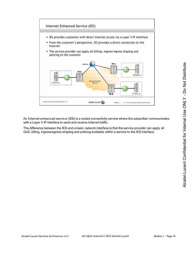
IES provides customers with direct Internet access via a Layer 3 IP interface
From the customer’s perspective, IES provides a direct connection to the
Internet
The service provider can apply all billing, ingress/egress shaping and
policing to the customer
Internet Enhanced Service (IES)
An Internet enhanced service (IES) is a routed connectivity service where the subscriber communicateswith a Layer 3 IP interface to send and receive Internet traffic.
The difference between the IES and a basic network interface is that the service provider can apply allQoS, billing, ingress/egress shaping and policing available within a service to the IES interface.

7/21/2019 Services Architecture v3.2 Student Guide Download
http://slidepdf.com/reader/full/services-architecture-v32-student-guide-download 38/429
Alcatel-Lucent Services Architecture v3.2 Module 1 – Page 20All rights reserved © 2012 Alcatel-Lucent
Services Overview & Implementation
Section 2 — Transport and Service Label Signaling

7/21/2019 Services Architecture v3.2 Student Guide Download
http://slidepdf.com/reader/full/services-architecture-v32-student-guide-download 39/429
Alcatel-Lucent Services Architecture v3.2 Module 1 – Page 21All rights reserved © 2012 Alcatel-Lucent
Module 1 | 21 All rights reserved ©2012 Alcatel-LucentAlcatel-Lucent Services Architecture v 3.2
Section Objectives
After successfully completing this section, you will be able to:
Explain how customer data is transmitted across the service
provider network (MPLS vs. GRE tunnels)
Explain the encapsulation of service data with a service label and
transport label
Explain how service labels are signaled

7/21/2019 Services Architecture v3.2 Student Guide Download
http://slidepdf.com/reader/full/services-architecture-v32-student-guide-download 40/429
Alcatel-Lucent Services Architecture v3.2 Module 1 – Page 22All rights reserved © 2012 Alcatel-Lucent
Module 1 | 22 All rights reserved ©2012 Alcatel-LucentAlcatel-Lucent Services Architecture v 3.2
Transport Tunnels and Service Tunnels
MPLS or GRE tunnels are used to transmit customer data across the service
provider network
Multiple service tunnels can be carried within a transport tunnel
Multiple transport tunnels can be configured on a single network port
Inner service label defines the service tunnel; outer transport label defines
the transport tunnel
All the IP/MPLS VPN services described in section one use MPLS or GRE tunnels to transmit customerdata across the service provider network. When MPLS is used, customer data is encapsulated with twoMPLS labels; an outer transport label and an inner service label.
Alcatel-Lucent routers are connected to physical links that are used to carry traffic. When a service is setup using MPLS, transport LSP tunnels are set up between provider edge, or PE, routers. Each service orcustomer sends traffic through a service tunnel within the transport LSP tunnel. Transport tunnel LSPs are
identified by MPLS labels that are swapped at each intermediate router, also known as a transit LSR,along the LSP from the ingress to the egress of the MPLS network.
The service label, or VC label, is used to identify which service or customer owns the packet. In theidentification process, the label is attached at the ingress point and does not change value as the packettravels from ingress to egress.
7/21/2019 Services Architecture v3.2 Student Guide Download
http://slidepdf.com/reader/full/services-architecture-v32-student-guide-download 41/429
Alcatel-Lucent Services Architecture v3.2 Module 1 – Page 23All rights reserved © 2012 Alcatel-Lucent
Module 1 | 23 All rights reserved ©2012 Alcatel-LucentAlcatel-Lucent Services Architecture v 3.2
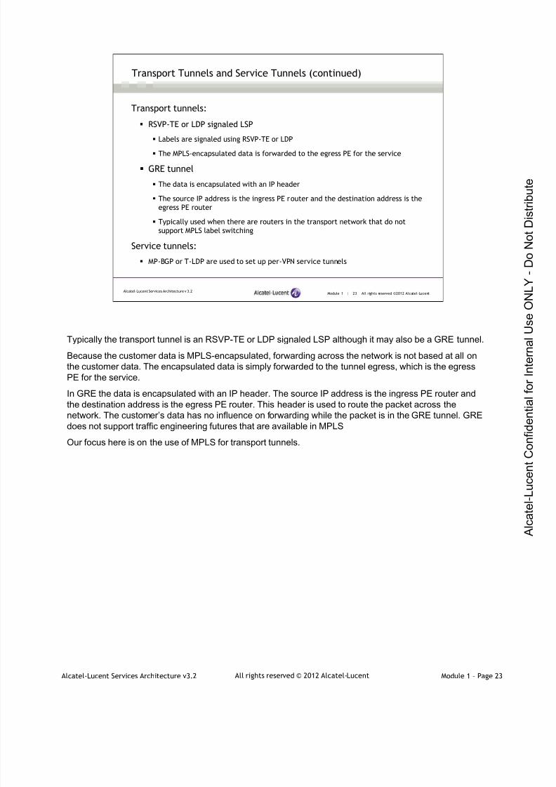
Transport Tunnels and Service Tunnels (continued)
Transport tunnels:
RSVP-TE or LDP signaled LSP
Labels are signaled using RSVP-TE or LDP
The MPLS-encapsulated data is forwarded to the egress PE for the service
GRE tunnel
The data is encapsulated with an IP header
The source IP address is the ingress PE router and the destination address is the
egress PE router
Typically used when there are routers in the transport network that do not
support MPLS label switching
Service tunnels:
MP-BGP or T-LDP are used to set up per-VPN service tunnels
Typically the transport tunnel is an RSVP-TE or LDP signaled LSP although it may also be a GRE tunnel.
Because the customer data is MPLS-encapsulated, forwarding across the network is not based at all onthe customer data. The encapsulated data is simply forwarded to the tunnel egress, which is the egressPE for the service.
In GRE the data is encapsulated with an IP header. The source IP address is the ingress PE router andthe destination address is the egress PE router. This header is used to route the packet across the
network. The customer’s data has no influence on forwarding while the packet is in the GRE tunnel. GREdoes not support traffic engineering futures that are available in MPLS
Our focus here is on the use of MPLS for transport tunnels.

7/21/2019 Services Architecture v3.2 Student Guide Download
http://slidepdf.com/reader/full/services-architecture-v32-student-guide-download 42/429
Alcatel-Lucent Services Architecture v3.2 Module 1 – Page 24All rights reserved © 2012 Alcatel-Lucent
Module 1 | 24 All rights reserved ©2012 Alcatel-LucentAlcatel-Lucent Services Architecture v 3.2
Transport and Service Label Encapsulation
MPLS encapsulation of VPN service traffic
DLC header — Layer 2 header used to transport the MPLS packet
MPLS transport (outer) label — The label signaled by the next-hop PE
Service (inner) label — The service, or virtual circuit (VC) label that
identifies the service the packet belongs to
Control word — Optional and primarily used for ATM or Frame Relay
services
Service packet —The customer data being transported by the service
Services over MPLS
In an IP/MPLS service network, data is encapsulated with at least two labels, the transport label and theservice label.
Data Link Control Header (DLC Header) - a Layer 2 header used to transport the MPLS packet. In manycases, the data link, or Layer 2, header in use is Ethernet. In this case, all of the following apply: a 14-byteDLC header, a 6-byte destination MAC address, a 6-byte source MAC address and a 2-byte Ethertypefield (0x8847 for MPLS or 0x0800 for IP/GRE). The 7750 SR also supports packet over SONET/SDH(POS).
When services are configured over MPLS, customer traffic is encapsulated in MPLS frames and sent overMPLS tunnels. A service label, or VC label, that indicates a specific customer connection, such as aFrame Relay DLCI, is pushed into the label stack between the transport tunnel label and the packet data.
An optional service-specific control word may be placed between the packet data and the service label.The control word is used for frame sequencing and/or carrying service-specific information, such asFrame Relay forward explicit congestion notification (FECN) and backward explicit congestion notification(BECN) information. At the tunnel-end, the service label is used to find the customer interface over whichthe traffic is sent. The control word, if present, is used to convert the encapsulated customer traffic into itsnative format.
Note: do not confuse VC Label with the VC ID that is used for service provisioning.

7/21/2019 Services Architecture v3.2 Student Guide Download
http://slidepdf.com/reader/full/services-architecture-v32-student-guide-download 43/429
Alcatel-Lucent Services Architecture v3.2 Module 1 – Page 25All rights reserved © 2012 Alcatel-Lucent
Module 1 | 25 All rights reserved ©2012 Alcatel-LucentAlcatel-Lucent Services Architecture v 3.2
Transport and Service Label Encapsulation (continued)
GRE encapsulation of VPN service traffic
IP header and the GRE header are used instead of the MPLS transport label
A service label is still required to demultiplex the packet to the appropriate
service
The service provider routers use the GRE header to route the packet across
the network
Services over GRE
When GRE is used to transport services, an MPLS transport label is not used. Instead, an IP header isused, where the source IP address is the local PE router and the destination IP address is the far-end PErouter. The minimum GRE header consists of 4 bytes: 2 for the flags, and 2 are used as protocol type files(contains the protocol ID of the payload packet). The MPLS protocol ID, which identifies the MPLS servicelabel, is 0x8847. It is important to note that in this case, even though GRE is used for transport, an MPLSservice label still exists so that the far-end PE can de-multiplex the service correctly. Therefore, unlike withMPLS transport labels, there is no label swapping at each router in the service provider’s network.
Rather, the outer IP header is used to forward the packet through the service provider network; as such,the IP header is not swapped at each router. The GRE IP header is stripped at the far-end provider edgerouter, which then uses the service label to demultiplex the service. At this point, the service label isstripped before the frame is passed to the customer. The main application of GRE would be in the casethat a service provider has transport routerss (P routers) that are not MPLS-capable. In this case, GREcould be used to encapsulate the frame and only MPLS would be required on the service endpoint routers(PE routers). In general, if MPLS-capable routers are available, the MPLS will be utilized for the transporttunnel.
7/21/2019 Services Architecture v3.2 Student Guide Download
http://slidepdf.com/reader/full/services-architecture-v32-student-guide-download 44/429
Alcatel-Lucent Services Architecture v3.2 Module 1 – Page 26All rights reserved © 2012 Alcatel-Lucent
Module 1 | 26 All rights reserved ©2012 Alcatel-LucentAlcatel-Lucent Services Architecture v 3.2
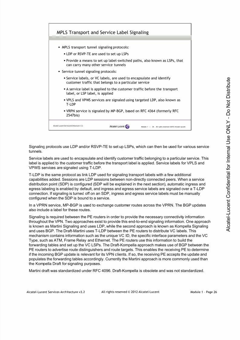
MPLS Transport and Service Label Signaling
MPLS transport tunnel signaling protocols:
LDP or RSVP-TE are used to set up LSPs
Provide a means to set up label-switched paths, also known as LSPs, thatcan carry many other service tunnels
Service tunnel signaling protocols:
Service labels, or VC labels, are used to encapsulate and identify
customer traffic that belongs to a particular service
A service label is applied to the customer traffic before the transport
label, or LSP label, is applied
VPLS and VPWS services are signaled using targeted LDP, also known as
T-LDP
VRPN service is signaled by MP-BGP, based on RFC 4364 (formerly RFC
2547bis)
Signaling protocols use LDP and/or RSVP-TE to set up LSPs, which can then be used for various servicetunnels.
Service labels are used to encapsulate and identify customer traffic belonging to a particular service. Thislabel is applied to the customer traffic before the transport label is applied. Service labels for VPLS andVPWS services are signaled using T-LDP.
T-LDP is the same protocol as link LDP used for signaling transport labels with a few additional
capabilities added. Sessions are LDP sessions between non-directly connected peers. When a servicedistribution point (SDP) is configured (SDP will be explained in the next section), automatic ingress andegress labeling is enabled by default, and ingress and egress service labels are signaled over a T-LDPconnection. If signaling is turned off on an SDP, ingress and egress service labels must be manuallyconfigured when the SDP is bound to a service.
In a VPRN service, MP-BGP is used to exchange customer routes across the VPRN. The BGP updatesalso include a label for these routes.
Signaling is required between the PE routers in order to provide the necessary connectivity informationthroughout the VPN. Two approaches exist to provide this end-to-end signaling information. One approachis known as Martini Signaling and uses LDP, while the second approach is known as Kompella Signalingand uses BGP. The Draft-Martini uses T-LDP between the PE routers to distribute VC labels. Thismechanism contains information such as the unique VC ID, the specific interface parameters and the VCType, such as ATM, Frame Relay and Ethernet. The PE routers use this information to build theforwarding tables and set up the VC LSPs. The Draft-Kompella approach makes use of BGP between thePE routers to advertise route distinguishers and route targets. This enables the receiving PE to determineif the incoming BGP update is relevant for its VPN clients. If so, the receiving PE accepts the update andpopulates the forwarding tables accordingly. Currently the Martini approach is more commonly used thanthe Kompella Draft for signaling purposes.
Martini draft was standardized under RFC 4096. Draft-Kompella is obsolete and was not standardized.
7/21/2019 Services Architecture v3.2 Student Guide Download
http://slidepdf.com/reader/full/services-architecture-v32-student-guide-download 45/429
Alcatel-Lucent Services Architecture v3.2 Module 1 – Page 27All rights reserved © 2012 Alcatel-Lucent
Module 1 | 27 All rights reserved ©2012 Alcatel-LucentAlcatel-Lucent Services Architecture v 3.2
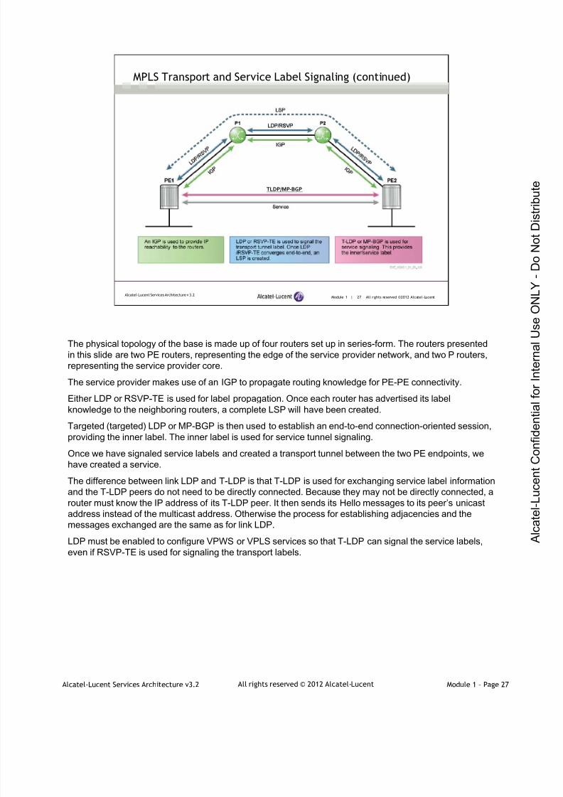
MPLS Transport and Service Label Signaling (continued)
TLDP/MP‐BGP
The physical topology of the base is made up of four routers set up in series-form. The routers presentedin this slide are two PE routers, representing the edge of the service provider network, and two P routers,representing the service provider core.
The service provider makes use of an IGP to propagate routing knowledge for PE-PE connectivity.
Either LDP or RSVP-TE is used for label propagation. Once each router has advertised its labelknowledge to the neighboring routers, a complete LSP will have been created.
Targeted (targeted) LDP or MP-BGP is then used to establish an end-to-end connection-oriented session,providing the inner label. The inner label is used for service tunnel signaling.
Once we have signaled service labels and created a transport tunnel between the two PE endpoints, wehave created a service.
The difference between link LDP and T-LDP is that T-LDP is used for exchanging service label informationand the T-LDP peers do not need to be directly connected. Because they may not be directly connected, arouter must know the IP address of its T-LDP peer. It then sends its Hello messages to its peer’s unicastaddress instead of the multicast address. Otherwise the process for establishing adjacencies and themessages exchanged are the same as for link LDP.
LDP must be enabled to configure VPWS or VPLS services so that T-LDP can signal the service labels,even if RSVP-TE is used for signaling the transport labels.

7/21/2019 Services Architecture v3.2 Student Guide Download
http://slidepdf.com/reader/full/services-architecture-v32-student-guide-download 46/429
Alcatel-Lucent Services Architecture v3.2 Module 1 – Page 28All rights reserved © 2012 Alcatel-Lucent
Module 1 | 28 All rights reserved ©2012 Alcatel-LucentAlcatel-Lucent Services Architecture v 3.2
MPLS Transport and Service Label Signaling (continued)
The exchange of service labels occurs when the pseudowire is created
The following outlines the service label signaling process:
1. PE2 sends PE1 a service label (11350)
2. PE1 sends PE2 a service label (21350)
3. Unidirectional service tunnels are created
4. PE1 uses the label (11350) to send traffic towards PE2
5. Likewise, PE2 uses label (21350) to send traffic towards PE1
The exchange of service labels occurs when the service is created.
7/21/2019 Services Architecture v3.2 Student Guide Download
http://slidepdf.com/reader/full/services-architecture-v32-student-guide-download 47/429
Alcatel-Lucent Services Architecture v3.2 Module 1 – Page 29All rights reserved © 2012 Alcatel-Lucent
Module 1 | 29 All rights reserved ©2012 Alcatel-LucentAlcatel-Lucent Services Architecture v 3.2
MPLS Transport and Service Label Signaling (continued)
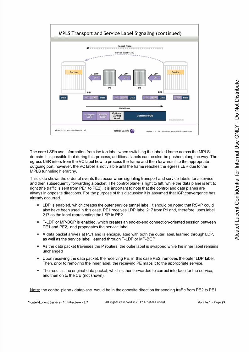
The core LSRs use information from the top label when switching the labeled frame across the MPLSdomain. It is possible that during this process, additional labels can be also be pushed along the way. Theegress LER infers from the VC label how to process the frame and then forwards it to the appropriateoutgoing port; however, the VC label is not visible until the frame reaches the egress LER due to theMPLS tunneling hierarchy.
This slide shows the order of events that occur when signaling transport and service labels for a service
and then subsequently forwarding a packet. The control plane is right to left, while the data plane is left toright (the traffic is sent from PE1 to PE2). It is important to note that the control and data planes arealways in opposite directions. For the purpose of this discussion it is assumed that IGP convergence hasalready occurred.
LDP is enabled, which creates the outer service tunnel label. It should be noted that RSVP couldalso have been used in this case. PE1 receives LDP label 217 from P1 and, therefore, uses label217 as the label representing the LSP to PE2
T-LDP or MP-BGP is enabled, which creates an end-to-end connection-oriented session betweenPE1 and PE2, and propagates the service label
A data packet arrives at PE1 and is encapsulated with both the outer label, learned through LDP,as well as the service label, learned through T-LDP or MP-BGP
As the data packet traverses the P routers, the outer label is swapped while the inner label remainsunchanged
Upon receiving the data packet, the receiving PE, in this case PE2, removes the outer LDP label.Then, prior to removing the inner label, the receiving PE maps it to the appropriate service.
The result is the original data packet, which is then forwarded to correct interface for the service,and then on to the CE (not shown).
Note: the control plane / dataplane would be in the opposite direction for sending traffic from PE2 to PE1

7/21/2019 Services Architecture v3.2 Student Guide Download
http://slidepdf.com/reader/full/services-architecture-v32-student-guide-download 48/429
Alcatel-Lucent Services Architecture v3.2 Module 1 – Page 30All rights reserved © 2012 Alcatel-Lucent
Services Overview & Implementation
Section 3 ― Service Components

7/21/2019 Services Architecture v3.2 Student Guide Download
http://slidepdf.com/reader/full/services-architecture-v32-student-guide-download 49/429
Alcatel-Lucent Services Architecture v3.2 Module 1 – Page 31All rights reserved © 2012 Alcatel-Lucent
Module 1 | 31 All rights reserved ©2012 Alcatel-LucentAlcatel-Lucent Services Architecture v 3.2
Section Objectives
After successfully completing this section, you will be able to:
Describe the main components required to configure Alcatel-Lucent
services (SAP, service ID, VC-ID, SDP)
Explain the concept of SAP and encapsulation identifier
Describe the operation of a local service
Configure and verify a local service
Describe the operation of a distributed service
Define a service distribution point (SDP) and list its characteristics
Configure and verify a distributed service
7/21/2019 Services Architecture v3.2 Student Guide Download
http://slidepdf.com/reader/full/services-architecture-v32-student-guide-download 50/429
Alcatel-Lucent Services Architecture v3.2 Module 1 – Page 32All rights reserved © 2012 Alcatel-Lucent
Module 1 | 32 All rights reserved ©2012 Alcatel-LucentAlcatel-Lucent Services Architecture v 3.2
Service Components
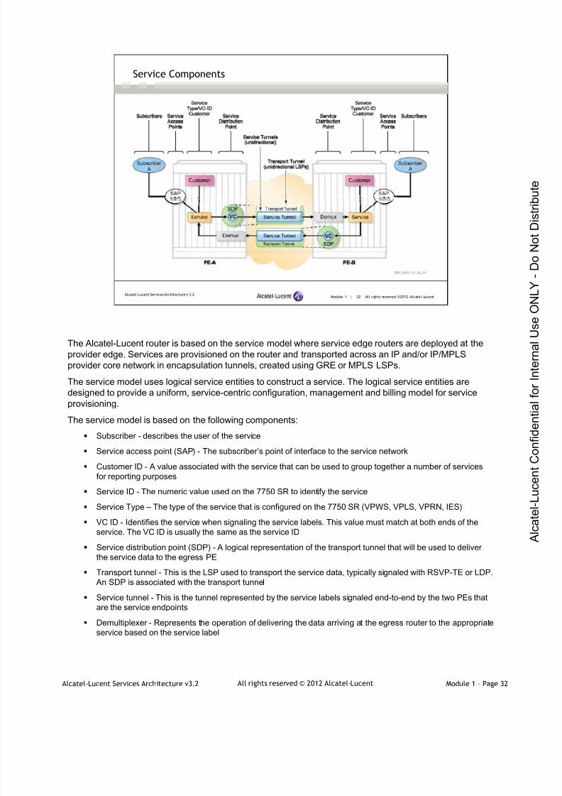
The Alcatel-Lucent router is based on the service model where service edge routers are deployed at theprovider edge. Services are provisioned on the router and transported across an IP and/or IP/MPLSprovider core network in encapsulation tunnels, created using GRE or MPLS LSPs.
The service model uses logical service entities to construct a service. The logical service entities aredesigned to provide a uniform, service-centric configuration, management and billing model for serviceprovisioning.
The service model is based on the following components:
Subscriber - describes the user of the service
Service access point (SAP) - The subscriber’s point of interface to the service network
Customer ID - A value associated with the service that can be used to group together a number of servicesfor reporting purposes
Service ID - The numeric value used on the 7750 SR to identify the service
Service Type – The type of the service that is configured on the 7750 SR (VPWS, VPLS, VPRN, IES)
VC ID - Identifies the service when signaling the service labels. This value must match at both ends of theservice. The VC ID is usually the same as the service ID
Service distribution point (SDP) - A logical representation of the transport tunnel that will be used to deliver
the service data to the egress PE
Transport tunnel - This is the LSP used to transport the service data, typically signaled with RSVP-TE or LDP. An SDP is associated with the transport tunnel
Service tunnel - This is the tunnel represented by the service labels signaled end-to-end by the two PEs thatare the service endpoints
Demultiplexer - Represents the operation of delivering the data arriving at the egress router to the appropriateservice based on the service label

7/21/2019 Services Architecture v3.2 Student Guide Download
http://slidepdf.com/reader/full/services-architecture-v32-student-guide-download 51/429
Alcatel-Lucent Services Architecture v3.2 Module 1 – Page 33All rights reserved © 2012 Alcatel-Lucent
Module 1 | 33 All rights reserved ©2012 Alcatel-LucentAlcatel-Lucent Services Architecture v 3.2
Customers and Subscribers
The terms ‘customers’ and ‘subscribers’ are used synonymously here
The customer ID is assigned when the customer account is created
To provision a service, a customer ID must be associated with the service atthe time of service creation
Multiple services can be associated with one customer
The customer ID for the service cannot be changed once the service is created
Once a service has been created with a customer association, it is not possible to edit the customerassociation; the service must be deleted and recreated with a new customer association. Once a serviceis created, the use of the customer ID is optional for navigating into the service configuration context.
Attempting to edit a service with the incorrect customer ID specified will result in an error.
The customer must be created before the service is created. The customer ID for the service cannot bechanged once the service is created. Although it is recommended that a globally consistent value be used
for the customer ID, it is never signaled to other PEs and has no effect on the service.
7/21/2019 Services Architecture v3.2 Student Guide Download
http://slidepdf.com/reader/full/services-architecture-v32-student-guide-download 52/429
Alcatel-Lucent Services Architecture v3.2 Module 1 – Page 34All rights reserved © 2012 Alcatel-Lucent
Module 1 | 34 All rights reserved ©2012 Alcatel-LucentAlcatel-Lucent Services Architecture v 3.2
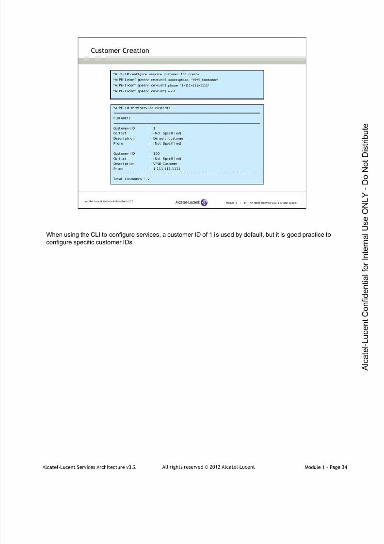
Customer Creation
*A:PE-1# configure service customer 100 create
*A: PE-1>confi g>servi ce>cust $ description "VPWS_Customer"
*A: PE-1>confi g>servi ce>cust $ phone "1-111-111-1111"
*A: PE-1>confi g>servi ce>cust $ exit
*A:PE-1# show servi ce customer
===============================================================================
Cust omer s
===============================================================================
Cust omer- I D : 1
Contact : (Not Specif i ed)
Descri pti on : Def aul t customer
Phone : (Not Speci f i ed)
Cust omer- I D : 100
Contact : (Not Specif i ed)
Descr i pt i on : VPWS_Customer
Phone : 1-111-111-1111
- - - - - - - - - - - - - - - - - - - - - - - - - - - - - - - - - - - - - - - - - - - - - - - - - - - - - - - - - - - - - - - - - - - - - - - - - - - - - - -
Tot al Customer s : 2
When using the CLI to configure services, a customer ID of 1 is used by default, but it is good practice toconfigure specific customer IDs
7/21/2019 Services Architecture v3.2 Student Guide Download
http://slidepdf.com/reader/full/services-architecture-v32-student-guide-download 53/429
Alcatel-Lucent Services Architecture v3.2 Module 1 – Page 35All rights reserved © 2012 Alcatel-Lucent
Module 1 | 35 All rights reserved ©2012 Alcatel-LucentAlcatel-Lucent Services Architecture v 3.2
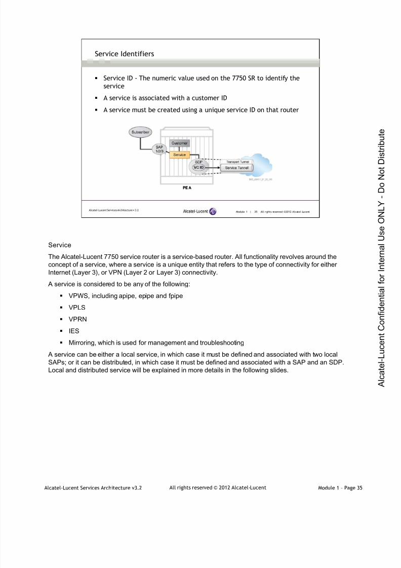
Service Identifiers
Service ID - The numeric value used on the 7750 SR to identify the
service
A service is associated with a customer ID
A service must be created using a unique service ID on that router
Service
The Alcatel-Lucent 7750 service router is a service-based router. All functionality revolves around theconcept of a service, where a service is a unique entity that refers to the type of connectivity for eitherInternet (Layer 3), or VPN (Layer 2 or Layer 3) connectivity.
A service is considered to be any of the following:
VPWS, including apipe, epipe and fpipe VPLS
VPRN
IES
Mirroring, which is used for management and troubleshooting
A service can be either a local service, in which case it must be defined and associated with two localSAPs; or it can be distributed, in which case it must be defined and associated with a SAP and an SDP.Local and distributed service will be explained in more details in the following slides.

7/21/2019 Services Architecture v3.2 Student Guide Download
http://slidepdf.com/reader/full/services-architecture-v32-student-guide-download 54/429
Alcatel-Lucent Services Architecture v3.2 Module 1 – Page 36All rights reserved © 2012 Alcatel-Lucent
Module 1 | 36 All rights reserved ©2012 Alcatel-LucentAlcatel-Lucent Services Architecture v 3.2
Service Creation
*A:PE-1# configure service epipe 50 customer 100 create
*A: PE-1>confi g>servi ce>epi pe$ no shutdown
*A: PE-1# show service i d 50 base
===============================================================================Servi ce Basic I nformati on
===============================================================================
Service I d : 50 Vpn I d : 0
Servi ce Type : Epi pe
Name : ( Not Speci f i ed)
Descri pti on : (Not Speci f i ed)
Cust omer I d : 100
Last Stat us Change: 01/ 30/2012 16:55: 09
Last Mgmt Change : 01/ 31/ 2012 11: 48: 48
Admi n Stat e : Up Oper Stat e : Down
MTU : 1514
Vc Swi tching : Fal se
SAP Count : 0 SDP Bi nd Count : 0
Per Svc Hashi ng : Di sabl ed
Force QTag Fwd : Di sabled
- - - - - - - - - - - - - - - - - - - - - - - - - - - - - - - - - - - - - - - - - - - - - - - - - - - - - - - - - - - - - - - - - - - - - - - - - - - - - - -
Servi ce Access & Desti nat i on Point s
- - - - - - - - - - - - - - - - - - - - - - - - - - - - - - - - - - - - - - - - - - - - - - - - - - - - - - - - - - - - - - - - - - - - - - - - - - - - - - -
I denti f i er Type AdmMTU OprMTU Adm Opr
- - - - - - - - - - - - - - - - - - - - - - - - - - - - - - - - - - - - - - - - - - - - - - - - - - - - - - - - - - - - - - - - - - - - - - - - - - - - - - -
No Matchi ng Entr i es
The slide shows the creating of an epipe service. The service is operationally down because it is notcompletely configured.
Service ID identifies the service on the local router. A service must be created using a unique service ID.Once a value is used for one service it cannot be used for another on that router.
Note: the vpn id is used to specify the VPN ID number, allowing you to identify virtual private networks(VPNs) by a VPN ID. If this parameter is not specified, the VPN ID uses the same service ID number.
Values 1 — 2147483647
Default null (0)

7/21/2019 Services Architecture v3.2 Student Guide Download
http://slidepdf.com/reader/full/services-architecture-v32-student-guide-download 55/429
Alcatel-Lucent Services Architecture v3.2 Module 1 – Page 37All rights reserved © 2012 Alcatel-Lucent
Module 1 | 37 All rights reserved ©2012 Alcatel-LucentAlcatel-Lucent Services Architecture v 3.2
Service Access Point (SAP)
A SAP is the subscriber’s point of interface to the service network
A SAP is specified as a physical port and an encapsulation identifier
To be used as a SAP, a port must be configured as an access port
SAP
1/2/3Service
Service Access Point (SAP)
A SAP is a logical entity that serves as the customer’s point of access into a service. Each subscriberservice is configured with at least one SAP. A SAP can only be configured on a port that has beenconfigured specifically as an ‘access’ port. The default configuration for a port is ‘network,’ which meansthat you may need to reconfigure a port before you can configure a SAP onto it. SAPs for IES and VPRNservices are configured on IP interfaces. A SAP is the subscriber-side entry and exit point for a service.
7/21/2019 Services Architecture v3.2 Student Guide Download
http://slidepdf.com/reader/full/services-architecture-v32-student-guide-download 56/429
Alcatel-Lucent Services Architecture v3.2 Module 1 – Page 38All rights reserved © 2012 Alcatel-Lucent
Module 1 | 38 All rights reserved ©2012 Alcatel-LucentAlcatel-Lucent Services Architecture v 3.2
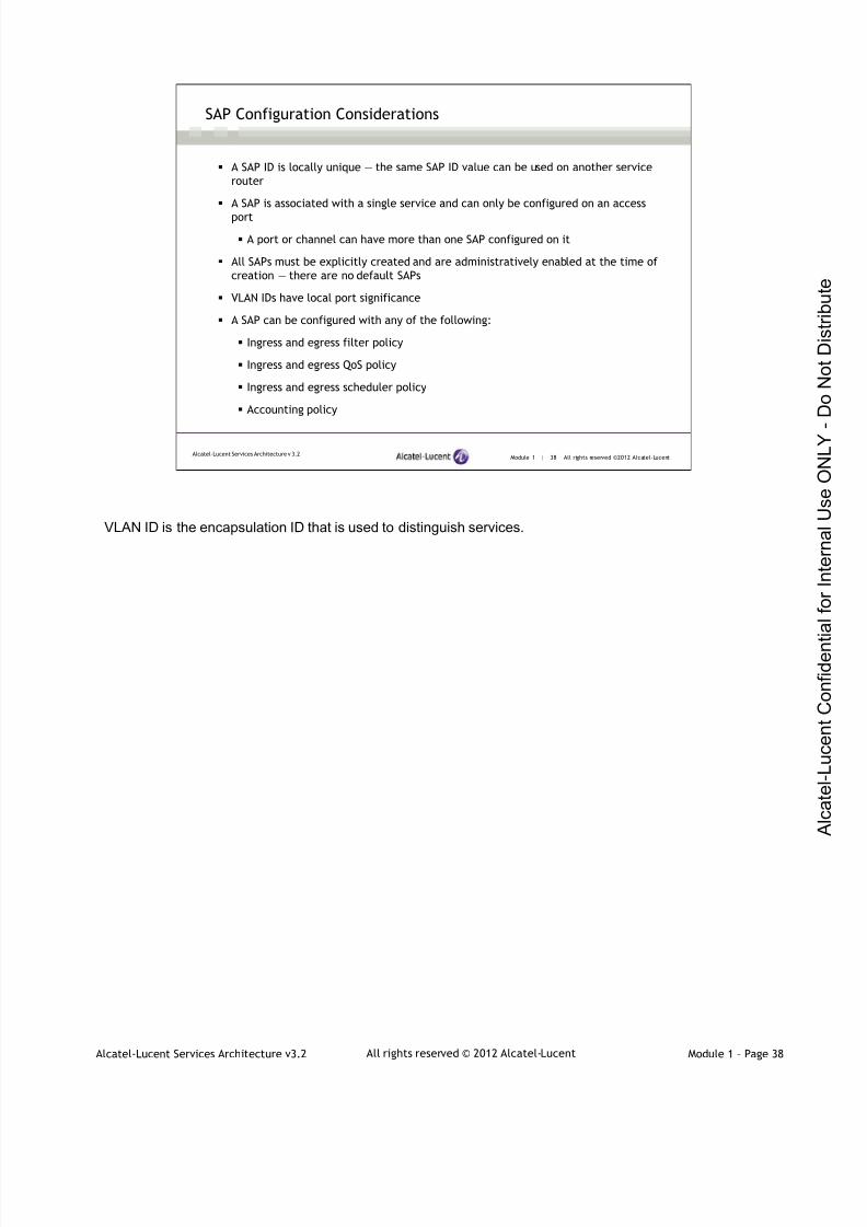
SAP Configuration Considerations
A SAP ID is locally unique — the same SAP ID value can be used on another service
router
A SAP is associated with a single service and can only be configured on an access
port
A port or channel can have more than one SAP configured on it
All SAPs must be explicitly created and are administratively enabled at the time of
creation — there are no default SAPs
VLAN IDs have local port significance
A SAP can be configured with any of the following:
Ingress and egress filter policy
Ingress and egress QoS policy
Ingress and egress scheduler policy
Accounting policy
VLAN ID is the encapsulation ID that is used to distinguish services.

7/21/2019 Services Architecture v3.2 Student Guide Download
http://slidepdf.com/reader/full/services-architecture-v32-student-guide-download 57/429
Alcatel-Lucent Services Architecture v3.2 Module 1 – Page 39All rights reserved © 2012 Alcatel-Lucent
Module 1 | 39 All rights reserved ©2012 Alcatel-LucentAlcatel-Lucent Services Architecture v 3.2
SAP ID
A SAP is a local entity to the service router and is uniquely
identified by the following:
The physical Ethernet port or SONET/SDH or TDM port and channel The encapsulation identifier (ID)
Depending on the encapsulation, a physical port or channel can
have more than one SAP associated with it
SAPs can only be created on ports or channels designated as
“access” in the physical port configuration
SAPs cannot be created on ports designated as core-facing
“network” ports
SAP Encapsulation Types and Identifiers
A SAP is local to the router and is uniquely identified by the following:
Physical Ethernet port or packet-over-SONET/SDH (POS) port and channel
Encapsulation identifier (ID)
The encapsulation identifier depends on the type of port used as the SAP. For example, if the SAP is anEthernet port, the encapsulation identifier can be a VLAN tag or a Q-in-Q tag. The encapsulation identifiermay be null in which case the SAP is simply the port.
The encapsulation type is an access property of a service Ethernet port or SONET/SDH or TDM channel.The appropriate encapsulation type for the port or channel depends on whether it is required to supportmultiple services on a single port/channel on the associated SAP, and the capabilities of the downstreamequipment connected to the port/channel. For example, a port can be tagged with IEEE 802.1Qencapsulation, referred to as dot1Q encapsulation, in which each individual tag can be identified with aservice. A SAP is created on a given port or channel by identifying the service with a specificencapsulation ID.
Depending on the encapsulation used, a physical port or POS channel can have more than one SAP
associated with it. Using dot1Q encapsulation or POS channels, the router can support either multipleservices for one customer, or one service for multiple customers.
SAPs cannot be created on ports designated as core-facing network ports bacause these ports have adifferent set of features enabled in software.
7/21/2019 Services Architecture v3.2 Student Guide Download
http://slidepdf.com/reader/full/services-architecture-v32-student-guide-download 58/429
Alcatel-Lucent Services Architecture v3.2 Module 1 – Page 40All rights reserved © 2012 Alcatel-Lucent
Module 1 | 40 All rights reserved ©2012 Alcatel-LucentAlcatel-Lucent Services Architecture v 3.2
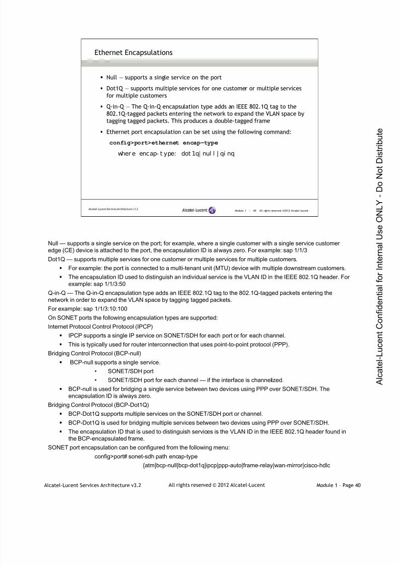
Ethernet Encapsulations
Null — supports a single service on the port
Dot1Q — supports multiple services for one customer or multiple services
for multiple customers
Q-in-Q — The Q-in-Q encapsulation type adds an IEEE 802.1Q tag to the
802.1Q-tagged packets entering the network to expand the VLAN space by
tagging tagged packets. This produces a double-tagged frame
Ethernet port encapsulation can be set using the following command:
config>port>ethernet encap-type
wher e encap- t ype: dot 1q| nul l | qi nq
Null — supports a single service on the port; for example, where a single customer with a single service customeredge (CE) device is attached to the port, the encapsulation ID is always zero. For example: sap 1/1/3
Dot1Q — supports multiple services for one customer or multiple services for multiple customers.
For example: the port is connected to a multi-tenant unit (MTU) device with multiple downstream customers.
The encapsulation ID used to distinguish an individual service is the VLAN ID in the IEEE 802.1Q header. Forexample: sap 1/1/3:50
Q-in-Q — The Q-in-Q encapsulation type adds an IEEE 802.1Q tag to the 802.1Q-tagged packets entering thenetwork in order to expand the VLAN space by tagging tagged packets.
For example: sap 1/1/3:10:100
On SONET ports the following encapsulation types are supported:
Internet Protocol Control Protocol (IPCP)
IPCP supports a single IP service on SONET/SDH for each port or for each channel.
This is typically used for router interconnection that uses point-to-point protocol (PPP).
Bridging Control Protocol (BCP-null)
BCP-null supports a single service.
• SONET/SDH port
• SONET/SDH port for each channel — if the interface is channelized.
BCP-null is used for bridging a single service between two devices using PPP over SONET/SDH. The
encapsulation ID is always zero.Bridging Control Protocol (BCP-Dot1Q)
BCP-Dot1Q supports multiple services on the SONET/SDH port or channel.
BCP-Dot1Q is used for bridging multiple services between two devices using PPP over SONET/SDH.
The encapsulation ID that is used to distinguish services is the VLAN ID in the IEEE 802.1Q header found inthe BCP-encapsulated frame.
SONET port encapsulation can be configured from the following menu:
config>port# sonet-sdh path encap-type
{atm|bcp-null|bcp-dot1q|ipcp|ppp-auto|frame-relay|wan-mirror|cisco-hdlc

7/21/2019 Services Architecture v3.2 Student Guide Download
http://slidepdf.com/reader/full/services-architecture-v32-student-guide-download 59/429
Alcatel-Lucent Services Architecture v3.2 Module 1 – Page 41All rights reserved © 2012 Alcatel-Lucent
Module 1 | 41 All rights reserved ©2012 Alcatel-LucentAlcatel-Lucent Services Architecture v 3.2
SAP Configuration
*A: PE- 1#confi gure port 1/1/ 3
*A: PE-1>confi g>port # shutdown
*A:PE-1>conf i g>port # ethernet
*A: PE-1>confi g>port >ether net# mode access
*A: PE-1>confi g>port >ether net# encap- t ype dot1q
*A:PE-1>conf i g>port >ethernet# exit*A: PE-1>confi g>port # no shutdown
*A:PE-1>conf i g>port # exi t
*A: PE-1# show port
===============================================================================
Port s on Slot 1
===============================================================================
Por t Admi n L ink Por t Cfg Oper LAG/ Por t Por t Por t SFP/XFP/
I d State State MTU MTU Bndl Mode Encp Type MDI MDX
- - - - - - - - - - - - - - - - - - - - - - - - - - - - - - - - - - - - - - - - - - - - - - - - - - - - - - - - - - - - - - - - - - - - - - - - - - - - - - -
1/1/1 Up Yes Up 1578 1578 - netw nul l gi ge
1/ 1/ 2 Down No Down 1578 1578 - netw nul l gi ge
1/1/3 Up Yes Up 1518 1518 - accs dotq gige
1/ 1/ 4 Down No Down 1578 1578 - netw nul l gi ge
1/ 1/ 5 Down No Down 1578 1578 - netw nul l gi ge
1/ 1/ 6 Down No Down 1578 1578 - netw nul l gi ge
1/ 1/ 7 Down No Down 1578 1578 - netw nul l gi ge
1/ 1/ 8 Down No Down 1578 1578 - netw nul l gi ge
1/ 1/ 9 Down No Down 1578 1578 - netw nul l gi ge
1/ 1/ 10 Down No Down 1578 1578 - netw nul l gi ge
===============================================================================
To be used as a SAP, a port must be configured as an access port. Ports are configured as network portsby default.
Note: when the ports are configured as Ethernet access ports with dot1q encapsulation, they areautomatically changed to an MTU (maximum transmission unit) of 1518. This defines the maximum size offrame that will be accepted for a service using this port as a SAP. By default the 7750 SR configures anEthernet access port to accept a standard-sized Ethernet frame. Since this port is configured for dot1q
encapsulation, the MTU is 1518. MTU consideration will be explained in detail in Module 2.Many other encapsulation types are possible. These depend on the MDA type of the port and the type ofservice being provisioned. SAP encapsulations are described in more detail in Module 2.
7/21/2019 Services Architecture v3.2 Student Guide Download
http://slidepdf.com/reader/full/services-architecture-v32-student-guide-download 60/429
Alcatel-Lucent Services Architecture v3.2 Module 1 – Page 42All rights reserved © 2012 Alcatel-Lucent
Module 1 | 42 All rights reserved ©2012 Alcatel-LucentAlcatel-Lucent Services Architecture v 3.2
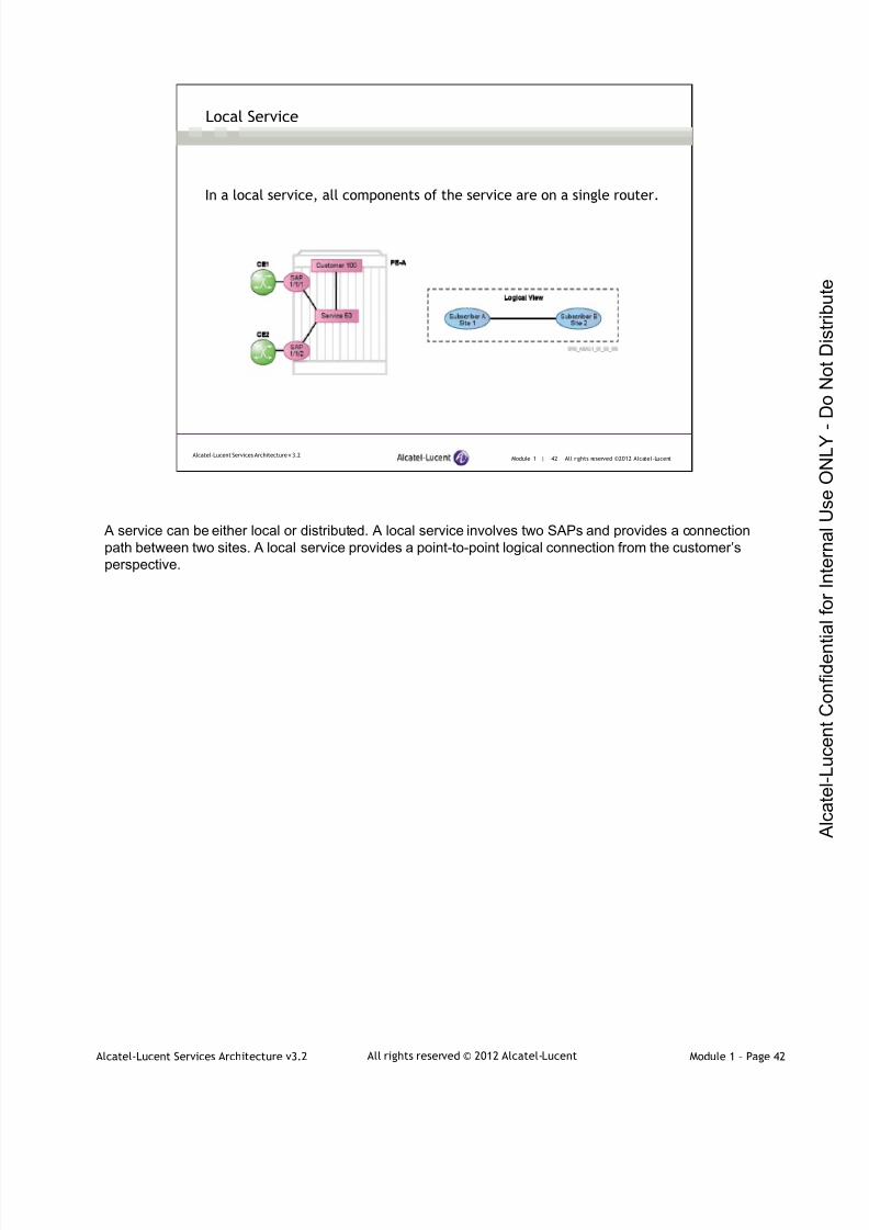
Local Service
In a local service, all components of the service are on a single router.
A service can be either local or distributed. A local service involves two SAPs and provides a connectionpath between two sites. A local service provides a point-to-point logical connection from the customer’sperspective.
7/21/2019 Services Architecture v3.2 Student Guide Download
http://slidepdf.com/reader/full/services-architecture-v32-student-guide-download 61/429
Alcatel-Lucent Services Architecture v3.2 Module 1 – Page 43All rights reserved © 2012 Alcatel-Lucent
Module 1 | 43 All rights reserved ©2012 Alcatel-LucentAlcatel-Lucent Services Architecture v 3.2
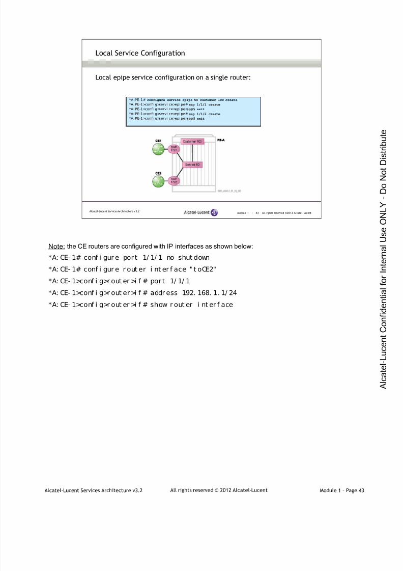
Local Service Configuration
Local epipe service configuration on a single router:
*A:PE-1# configure service epipe 50 customer 100 create*A: PE-1>confi g>servi ce>epi pe# sap 1/1/1 create
*A: PE-1>confi g>servi ce>epi pe>sap$ exit
*A: PE-1>confi g>servi ce>epi pe# sap 1/1/2 create
*A: PE-1>confi g>servi ce>epi pe>sap$ exit
Note: the CE routers are configured with IP interfaces as shown below:
*A: CE- 1# conf i gur e port 1/ 1/ 1 no shut down
*A: CE- 1# conf i gur e r out er i nt er f ace " t oCE2"
*A: CE- 1>conf i g>r out er >i f # port 1/ 1/ 1
*A: CE- 1>conf i g>r out er>i f # addr ess 192. 168. 1. 1/ 24
*A: CE- 1>conf i g>r out er >i f # show r out er i nt er f ace

7/21/2019 Services Architecture v3.2 Student Guide Download
http://slidepdf.com/reader/full/services-architecture-v32-student-guide-download 62/429
Alcatel-Lucent Services Architecture v3.2 Module 1 – Page 44All rights reserved © 2012 Alcatel-Lucent
Module 1 | 44 All rights reserved ©2012 Alcatel-LucentAlcatel-Lucent Services Architecture v 3.2
Local Service Verification
*A: PE-1>confi g>servi ce>epi pe# show service id 50 base
===============================================================================Servi ce Basic I nformati on===============================================================================Servi ce I d : 50 Vpn I d : 0
Servi ce Type : Epi peName : ( Not Speci f i ed)Descri pti on : (Not Specif i ed)Cust omer I d : 100Last St atus Change: 01/ 30/2012 16:55: 09Last Mgmt Change : 01/ 31/ 2012 15: 15: 21Admi n State : Up Oper State : UpMTU : 1514Vc Swi tching : Fal seSAP Count : 2 SDP Bi nd Count : 0Per Svc Hashing : Di sabl edForce QTag Fwd : Di sabl ed- - - - - - - - - - - - - - - - - - - - - - - - - - - - - - - - - - - - - - - - - - - - - - - - - - - - - - - - - - - - - - - - - - - - - - - - - - - - - - -Servi ce Access & Desti nati on Point s- - - - - - - - - - - - - - - - - - - - - - - - - - - - - - - - - - - - - - - - - - - - - - - - - - - - - - - - - - - - - - - - - - - - - - - - - - - - - - -I denti f i er Type AdmMTU OprMTU Adm Opr- - - - - - - - - - - - - - - - - - - - - - - - - - - - - - - - - - - - - - - - - - - - - - - - - - - - - - - - - - - - - - - - - - - - - - - - - - - - - - -sap:1/ 1/ 1 q-t ag 1514 1514 Up Upsap:1/ 1/ 2 q-t ag 1514 1514 Up Up===============================================================================
As shown in the slide, the epipe service is up and the CE routers should be able to reach each other overthe Ethernet connection, as shown in the ping test below:
*A: CE- 1> ping 192.168.1.2 count 1
PI NG 192. 168. 1. 2 56 dat a byt es
64 byt es f r om 192. 168. 1. 2: i cmp_seq=1 t t l =64 t i me=4. 45ms.

7/21/2019 Services Architecture v3.2 Student Guide Download
http://slidepdf.com/reader/full/services-architecture-v32-student-guide-download 63/429
Alcatel-Lucent Services Architecture v3.2 Module 1 – Page 45All rights reserved © 2012 Alcatel-Lucent
Module 1 | 45 All rights reserved ©2012 Alcatel-LucentAlcatel-Lucent Services Architecture v 3.2
Distributed Service
A distributed service has components on multiple routers and uses the
IP/MPLS network to connect the service and deliver data
SDP binding is required to signal the service labels and define thetransport to the remote router
A distributed service has components on multiple routers and uses the IP/MPLS network to connect theservice and deliver data.
Distributed service spans more than one router. It uses SDPs to direct traffic to another router; traffic istransported by a transport tunnel through a service tunnel.

7/21/2019 Services Architecture v3.2 Student Guide Download
http://slidepdf.com/reader/full/services-architecture-v32-student-guide-download 64/429
Alcatel-Lucent Services Architecture v3.2 Module 1 – Page 46All rights reserved © 2012 Alcatel-Lucent
Module 1 | 46 All rights reserved ©2012 Alcatel-LucentAlcatel-Lucent Services Architecture v 3.2
Service Distribution Point (SDP) Characteristics
A service distribution point (SDP) is a logical entity used to direct traffic
from one router to another through a unidirectional service tunnel
SDPs are locally unique; the same SDP ID can be used on another router
SDPs use the system IP address to identify far-end destinations
An SDP is not specific to one service; many services can use the same SDP
All services bound to an SDP use the same encapsulation
Operations on an SDP will affect all services that are bound to that SDP
A service distribution point (SDP) acts as a logical way to direct traffic from one router to another througha unidirectional service tunnel. The SDP terminates at the far-end router, which directs packets to thecorrect service egress SAPs on that device. A distributed service consists of a configuration with at leastone SAP on a local router, one SAP on a remote router, and an SDP binding the service to the servicetunnel.
An SDP has the following characteristics:
An SDP is locally unique to a router. The same SDP ID can appear on other routers.
An SDP uses the system IP address to identify the far-end edge router.
An SDP is not specific to any one service or type of service. Once an SDP is created, services arebound to the SDP. An SDP can also have more than one service type associated with it.
All services mapped to an SDP use the same transport encapsulation type defined for the SDP — either GRE or MPLS.
An SDP is a management entity. Even though the SDP configuration and the services carriedwithin are independent, they are related objects. Operations on the SDP affect all the servicesassociated with the SDP. For example, the operational and administrative state of an SDP controlsthe state of services bound to the SDP.
A return-path SDP is needed when a far-end device communicates with a local device. Each device musthave an SDP defined for every remote router that is receiving service. Before a distributed service can beconfigured, SDPs must first be created.

7/21/2019 Services Architecture v3.2 Student Guide Download
http://slidepdf.com/reader/full/services-architecture-v32-student-guide-download 65/429
Alcatel-Lucent Services Architecture v3.2 Module 1 – Page 47All rights reserved © 2012 Alcatel-Lucent
Module 1 | 47 All rights reserved ©2012 Alcatel-LucentAlcatel-Lucent Services Architecture v 3.2
Binding an SDP to a Service
SDPs provide the binding between the control plane signaling of
service labels and the transport tunnels (LDP/RSVP or GRE)
To direct a service to use an SDP for distribution, the service isjoined to the SDP using SDP binding
A service label is not signaled unless the service is bound to an SDP
Because all service distribution relies on the SDP, the transport is
most often RSVP with fast rerouting capabilities
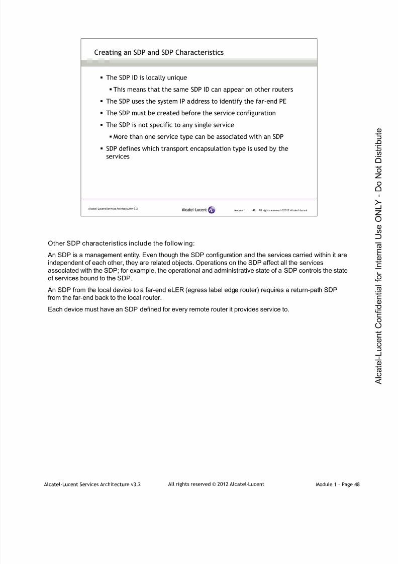
7/21/2019 Services Architecture v3.2 Student Guide Download
http://slidepdf.com/reader/full/services-architecture-v32-student-guide-download 66/429
Alcatel-Lucent Services Architecture v3.2 Module 1 – Page 48All rights reserved © 2012 Alcatel-Lucent
Module 1 | 48 All rights reserved ©2012 Alcatel-LucentAlcatel-Lucent Services Architecture v 3.2
Creating an SDP and SDP Characteristics
The SDP ID is locally unique
This means that the same SDP ID can appear on other routers
The SDP uses the system IP address to identify the far-end PE
The SDP must be created before the service configuration
The SDP is not specific to any single service
More than one service type can be associated with an SDP
SDP defines which transport encapsulation type is used by the
services
Other SDP characteristics include the follow ing:
An SDP is a management entity. Even though the SDP configuration and the services carried within it areindependent of each other, they are related objects. Operations on the SDP affect all the servicesassociated with the SDP; for example, the operational and administrative state of a SDP controls the stateof services bound to the SDP.
An SDP from the local device to a far-end eLER (egress label edge router) requires a return-path SDP
from the far-end back to the local router.
Each device must have an SDP defined for every remote router it provides service to.

7/21/2019 Services Architecture v3.2 Student Guide Download
http://slidepdf.com/reader/full/services-architecture-v32-student-guide-download 67/429
Alcatel-Lucent Services Architecture v3.2 Module 1 – Page 49All rights reserved © 2012 Alcatel-Lucent
Module 1 | 49 All rights reserved ©2012 Alcatel-LucentAlcatel-Lucent Services Architecture v 3.2
SDP Encapsulation Types
MPLS encapsulation:
Uses LDP or RSVP-TE for label signaling
LDP relies on an IGP to find its path
RSVP-TE requires additional configuration
RSVP-TE allows finer control of paths
GRE encapsulation:
Encapsulates traffic in an IP/GRE header, appears as an IP packet
Low control plane overhead
GRE uses normal IP routing to find a path
MPLS Encapsulation
MPLS uses LDP or RSVP-TE for label signaling
LDP relies on an IGP to find its path
RSVP-TE requires manual configuration, path can be loose or strict, may reserve bandwidth, andcan use fast reroute to speed convergence after change
Generic Routing Encapsulation (GRE)
Low control plane overhead
Uses an IGP to find a path from edge to edge
Convergence depends on the IGP

7/21/2019 Services Architecture v3.2 Student Guide Download
http://slidepdf.com/reader/full/services-architecture-v32-student-guide-download 68/429
Alcatel-Lucent Services Architecture v3.2 Module 1 – Page 50All rights reserved © 2012 Alcatel-Lucent
Module 1 | 50 All rights reserved ©2012 Alcatel-LucentAlcatel-Lucent Services Architecture v 3.2
Logical Service-Level View
Transport Tunnel
A transport tunnel is used by an SDP to direct traffic from one router to another.The diagram shows thatmultiple services can use the same SDP.
Multi-router VPWS and VPLS traffic is transported using unidirectional service tunnels. Service tunnelsoriginate on an SDP on one router and terminate at a destination router. The destination router directspackets to the correct service egress interfaces on that device. Service tunnels can be configured to use
either GRE or MPLS LSPs. Services that originate and terminate on the same router do not requireservice tunnels or SDPs.

7/21/2019 Services Architecture v3.2 Student Guide Download
http://slidepdf.com/reader/full/services-architecture-v32-student-guide-download 69/429
Alcatel-Lucent Services Architecture v3.2 Module 1 – Page 51All rights reserved © 2012 Alcatel-Lucent
Module 1 | 51 All rights reserved ©2012 Alcatel-LucentAlcatel-Lucent Services Architecture v 3.2
Single Subscriber ― Distributed VPWS Service
Each SDP identifies the destination-system-ID as the far-end address, thereby specifying the targetedLDP connection. The SDP ID is not transferred to the far-end system, therefore the SDP ID does not needto match. Although it is not necessary for the SDP ID to be identical on opposite sides of the servicetunnel, it is suggested. Alternately, the SDP ID must be locally unique in each system. In addition, it is notnecessary that the service ID be identical on each system. By default, the service ID equals the VC ID.
In the diagram in this slide, Subscriber A has two sites which are being connected by a VPWS. This
VPWS provides a virtual point-to-point connection across any existing IP/MPLS network infrastructure,while maintaining the appearance of a directly connected segment.

7/21/2019 Services Architecture v3.2 Student Guide Download
http://slidepdf.com/reader/full/services-architecture-v32-student-guide-download 70/429
Alcatel-Lucent Services Architecture v3.2 Module 1 – Page 52All rights reserved © 2012 Alcatel-Lucent
Module 1 | 52 All rights reserved ©2012 Alcatel-LucentAlcatel-Lucent Services Architecture v 3.2
Multiple Subscribers
Multiple services can be associated with the same SDP allowing subscribers to have access to multiplesites across multiple platforms for multiple services.
In the diagram in this slide, Subscriber A has two sites while Subscriber B has three sites. In relation toSubscriber A, Site 1 and Site 2 are connected by a point-to-point connection — a VPWS. In the case ofSubscriber B, each site requires access to all three locations, which is more indicative of a VPLS offering.Since services can be bound to multiple SDPs, the number of SDPs only needs to equal to the number of
connected neighbors, regardless of how many subscribers or services are being used.
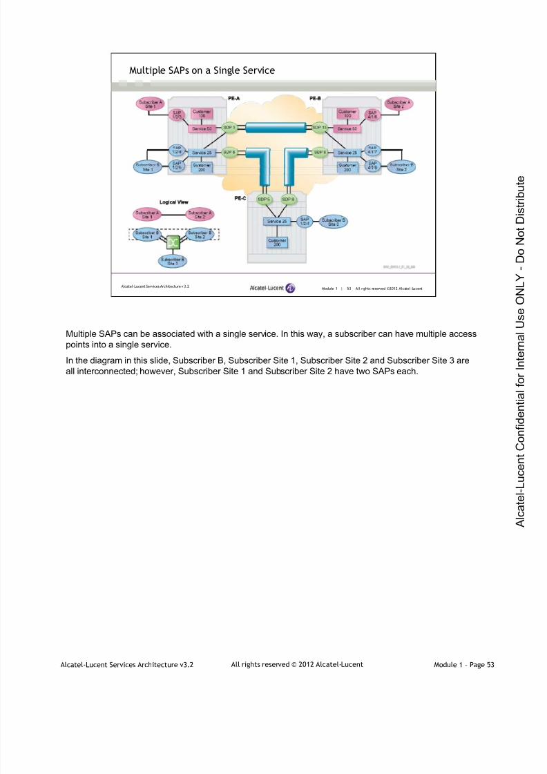
7/21/2019 Services Architecture v3.2 Student Guide Download
http://slidepdf.com/reader/full/services-architecture-v32-student-guide-download 71/429
Alcatel-Lucent Services Architecture v3.2 Module 1 – Page 53All rights reserved © 2012 Alcatel-Lucent
Module 1 | 53 All rights reserved ©2012 Alcatel-LucentAlcatel-Lucent Services Architecture v 3.2
Multiple SAPs on a Single Service
Multiple SAPs can be associated with a single service. In this way, a subscriber can have multiple accesspoints into a single service.
In the diagram in this slide, Subscriber B, Subscriber Site 1, Subscriber Site 2 and Subscriber Site 3 areall interconnected; however, Subscriber Site 1 and Subscriber Site 2 have two SAPs each.
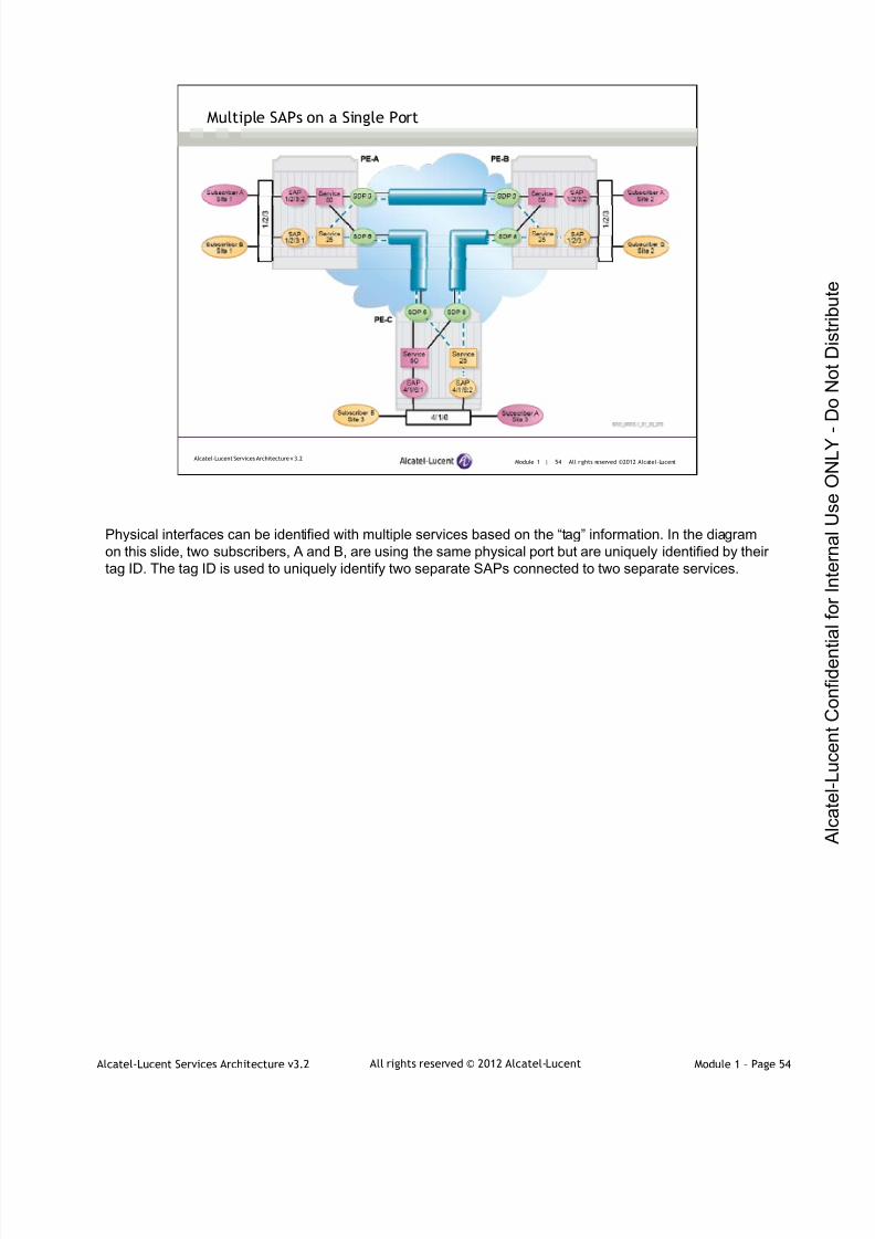
7/21/2019 Services Architecture v3.2 Student Guide Download
http://slidepdf.com/reader/full/services-architecture-v32-student-guide-download 72/429
Alcatel-Lucent Services Architecture v3.2 Module 1 – Page 54All rights reserved © 2012 Alcatel-Lucent
Module 1 | 54 All rights reserved ©2012 Alcatel-LucentAlcatel-Lucent Services Architecture v 3.2
Multiple SAPs on a Single Port
Physical interfaces can be identified with multiple services based on the “tag” information. In the diagramon this slide, two subscribers, A and B, are using the same physical port but are uniquely identified by theirtag ID. The tag ID is used to uniquely identify two separate SAPs connected to two separate services.
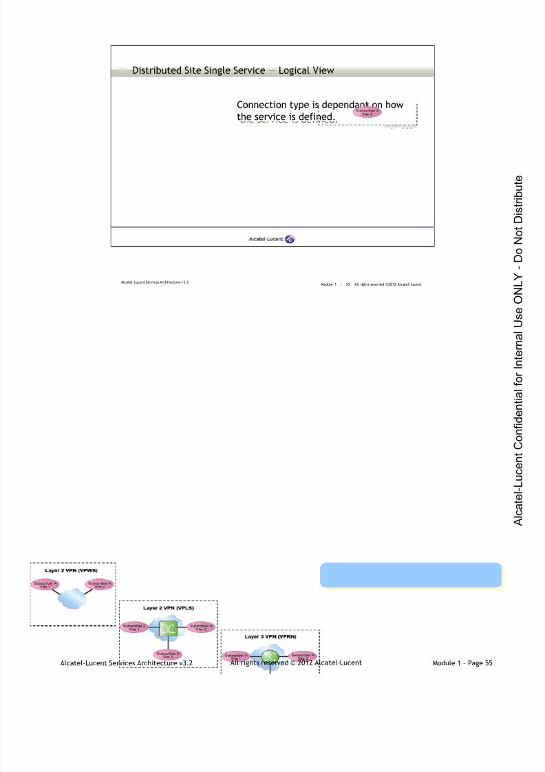
7/21/2019 Services Architecture v3.2 Student Guide Download
http://slidepdf.com/reader/full/services-architecture-v32-student-guide-download 73/429
Alcatel-Lucent Services Architecture v3.2 Module 1 – Page 55All rights reserved © 2012 Alcatel-Lucent
Module 1 | 55 All rights reserved ©2012 Alcatel-LucentAlcatel-Lucent Services Architecture v 3.2
Distributed Site Single Service ― Logical View
Connection type is dependant on how
the service is defined.
Connection type is dependant on how
the service is defined.
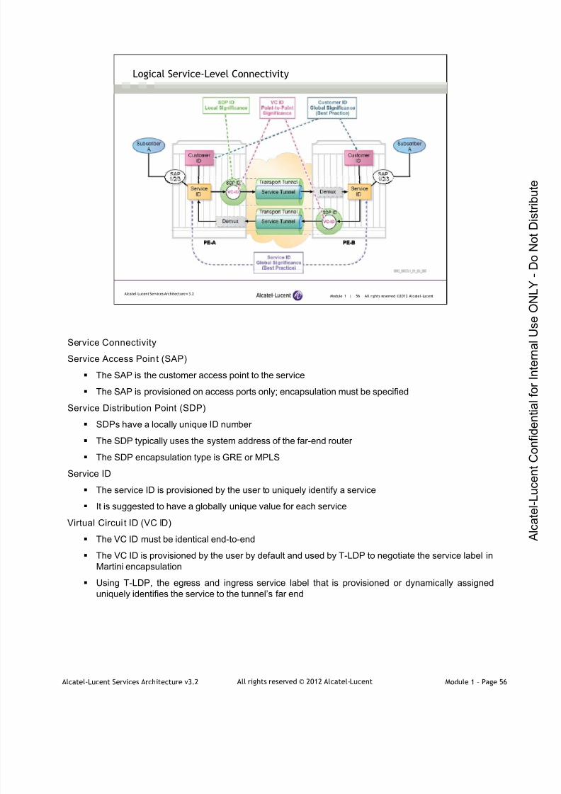
7/21/2019 Services Architecture v3.2 Student Guide Download
http://slidepdf.com/reader/full/services-architecture-v32-student-guide-download 74/429
Alcatel-Lucent Services Architecture v3.2 Module 1 – Page 56All rights reserved © 2012 Alcatel-Lucent
Module 1 | 56 All rights reserved ©2012 Alcatel-LucentAlcatel-Lucent Services Architecture v 3.2
Logical Service-Level Connectivity
Service Connectivity
Service Access Point (SAP)
The SAP is the customer access point to the service
The SAP is provisioned on access ports only; encapsulation must be specified
Service Distribution Point (SDP)
SDPs have a locally unique ID number
The SDP typically uses the system address of the far-end router
The SDP encapsulation type is GRE or MPLS
Service ID
The service ID is provisioned by the user to uniquely identify a service
It is suggested to have a globally unique value for each service
Virtual Circui t ID (VC ID)
The VC ID must be identical end-to-end
The VC ID is provisioned by the user by default and used by T-LDP to negotiate the service label inMartini encapsulation
Using T-LDP, the egress and ingress service label that is provisioned or dynamically assigneduniquely identifies the service to the tunnel’s far end

7/21/2019 Services Architecture v3.2 Student Guide Download
http://slidepdf.com/reader/full/services-architecture-v32-student-guide-download 75/429
Alcatel-Lucent Services Architecture v3.2 Module 1 – Page 57All rights reserved © 2012 Alcatel-Lucent
Services Overview & Implementation
Section 4 ― Distributed Service Configuration

7/21/2019 Services Architecture v3.2 Student Guide Download
http://slidepdf.com/reader/full/services-architecture-v32-student-guide-download 76/429
Alcatel-Lucent Services Architecture v3.2 Module 1 – Page 58All rights reserved © 2012 Alcatel-Lucent
Module 1 | 58 All rights reserved ©2012 Alcatel-LucentAlcatel-Lucent Services Architecture v 3.2
Distributed Service Configuration
The following steps must be completed for a successful distributed
service operation:
IGP configuration - ensure that routing tables have system addresses
Signaling transport labels are enabled for either LDP or RSVP
LDP has to be enabled for dynamic signaling of service labels using T-LDP
Creation of a path — if using RSVP
Creation of LSP and bind path — if using RSVP
Creation and binding of SDP to LSP — if using RSVP or select LDP
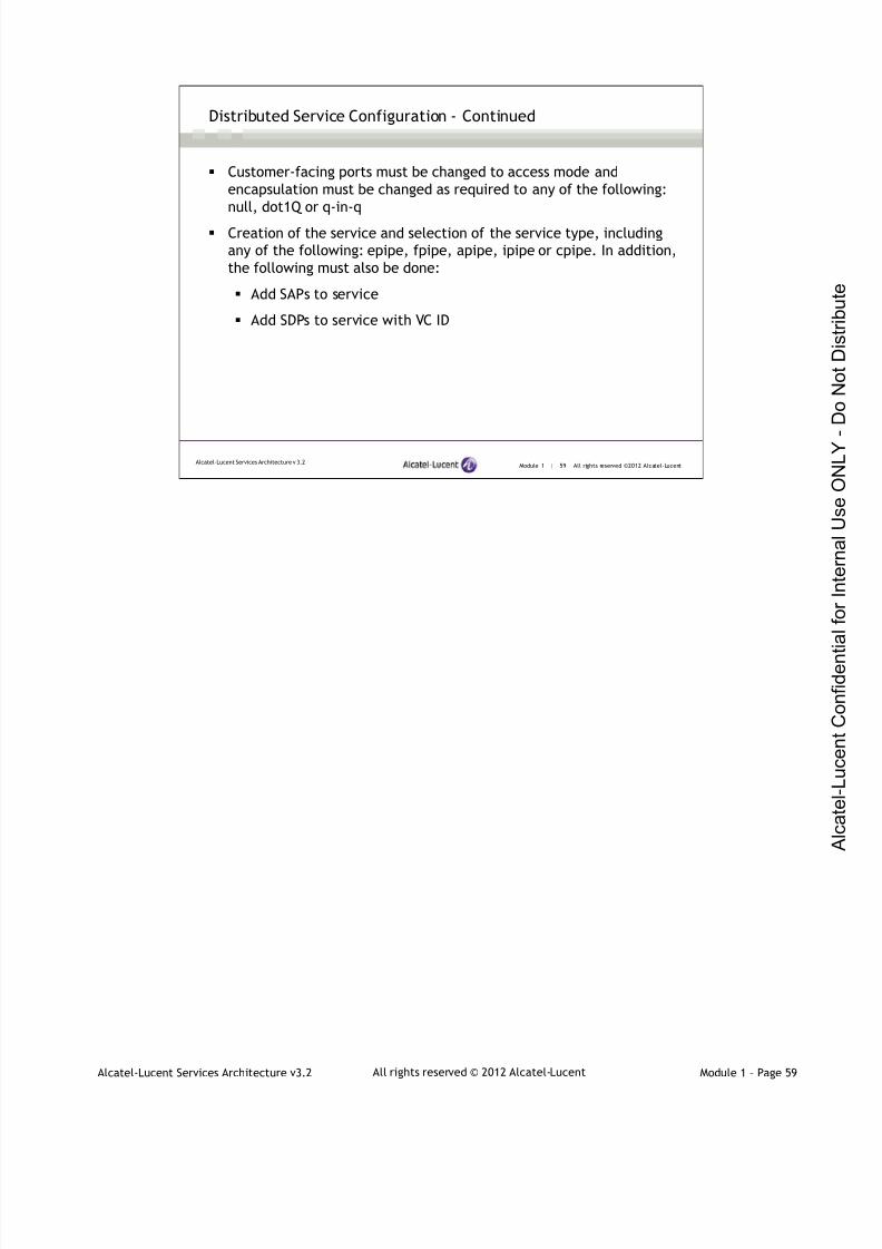
7/21/2019 Services Architecture v3.2 Student Guide Download
http://slidepdf.com/reader/full/services-architecture-v32-student-guide-download 77/429
Alcatel-Lucent Services Architecture v3.2 Module 1 – Page 59All rights reserved © 2012 Alcatel-Lucent
Module 1 | 59 All rights reserved ©2012 Alcatel-LucentAlcatel-Lucent Services Architecture v 3.2
Distributed Service Configuration - Continued
Customer-facing ports must be changed to access mode and
encapsulation must be changed as required to any of the following:
null, dot1Q or q-in-q
Creation of the service and selection of the service type, including
any of the following: epipe, fpipe, apipe, ipipe or cpipe. In addition,
the following must also be done:
Add SAPs to service
Add SDPs to service with VC ID
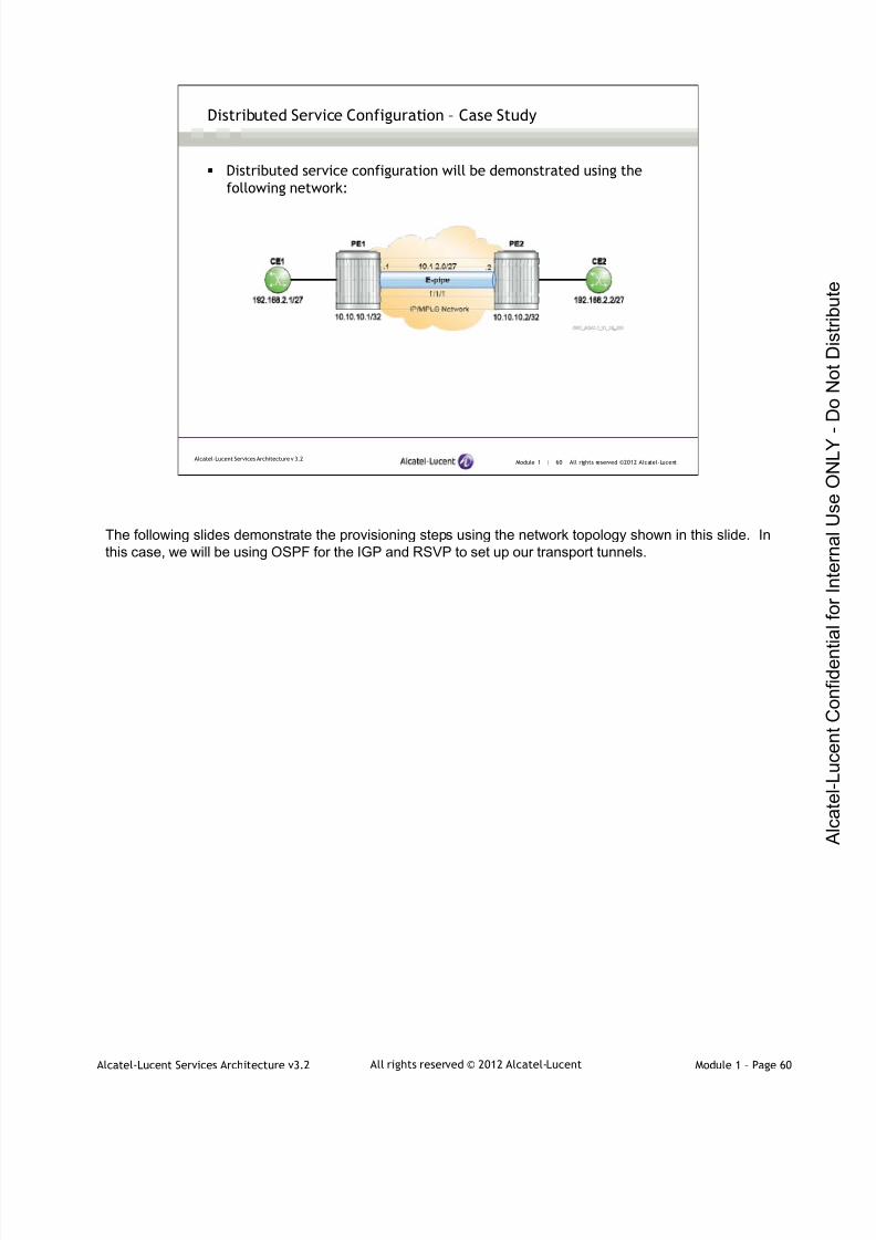
7/21/2019 Services Architecture v3.2 Student Guide Download
http://slidepdf.com/reader/full/services-architecture-v32-student-guide-download 78/429
Alcatel-Lucent Services Architecture v3.2 Module 1 – Page 60All rights reserved © 2012 Alcatel-Lucent
Module 1 | 60 All rights reserved ©2012 Alcatel-LucentAlcatel-Lucent Services Architecture v 3.2
Distributed Service Configuration – Case Study
Distributed service configuration will be demonstrated using the
following network:
The following slides demonstrate the provisioning steps using the network topology shown in this slide. Inthis case, we will be using OSPF for the IGP and RSVP to set up our transport tunnels.
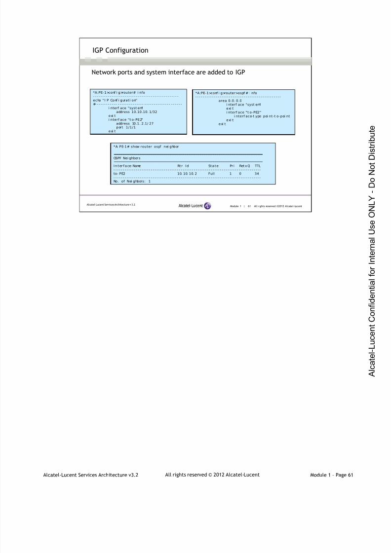
7/21/2019 Services Architecture v3.2 Student Guide Download
http://slidepdf.com/reader/full/services-architecture-v32-student-guide-download 79/429
Alcatel-Lucent Services Architecture v3.2 Module 1 – Page 61All rights reserved © 2012 Alcatel-Lucent
Module 1 | 61 All rights reserved ©2012 Alcatel-LucentAlcatel-Lucent Services Architecture v 3.2
IGP Configuration
Network ports and system interface are added to IGP
*A: PE-1# show router ospf nei ghbor
===============================================================================OSPF Nei ghbor s===============================================================================In t er face- Name Rt r I d St a t e Pr i Ret xQ TTL- - - - - - - - - - - - - - - - - - - - - - - - - - - - - - - - - - - - - - - - - - - - - - - - - - - - - - - - - - - - - - - - - - - - - - - - - - - - - - -to- PE2 10. 10. 10. 2 Full 1 0 34- - - - - - - - - - - - - - - - - - - - - - - - - - - - - - - - - - - - - - - - - - - - - - - - - - - - - - - - - - - - - - - - - - - - - - - - - - - - - - -No. of Nei ghbors: 1
*A:PE-1>conf i g>router# i nfo
- - - - - - - - - - - - - - - - - - - - - - - - - - - - - - - - - - - - - - - - - - - - - -echo "I P Conf i gurati on"#- - - - - - - - - - - - - - - - - - - - - - - - - - - - - - - - - - - - - - - - - - - - - -
i nterf ace "syst em"address 10.10.10. 1/32
exi ti nterf ace "t o-PE2"
address 10.1. 2.1/ 27port 1/1/1
exi t
*A:PE-1>conf i g>router>ospf # i nfo
- - - - - - - - - - - - - - - - - - - - - - - - - - - - - - - - - - - - - - - - - - - - - -area 0.0. 0.0
i nterf ace "syst em"exi ti nterf ace "t o-PE2"
i nterf ace-t ype poi nt-t o-poi ntexi t
exi t
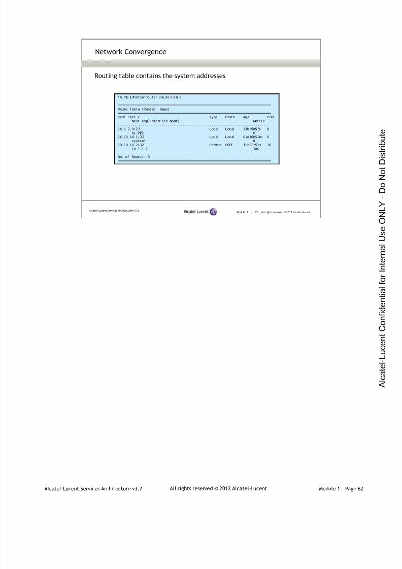
7/21/2019 Services Architecture v3.2 Student Guide Download
http://slidepdf.com/reader/full/services-architecture-v32-student-guide-download 80/429
Alcatel-Lucent Services Architecture v3.2 Module 1 – Page 62All rights reserved © 2012 Alcatel-Lucent
Module 1 | 62 All rights reserved ©2012 Alcatel-LucentAlcatel-Lucent Services Architecture v 3.2
Network Convergence
Routing table contains the system addresses
*A: PE- 1#show router route-t abl e
===============================================================================Route Tabl e (Rout er: Base)===============================================================================Dest Pref i x Type Proto Age Pref
Next Hop[ I nterf ace Name] Metr i c- - - - - - - - - - - - - - - - - - - - - - - - - - - - - - - - - - - - - - - - - - - - - - - - - - - - - - - - - - - - - - - - - - - - - - - - - - - - - - -10. 1. 2.0/27 Local Local 13h45m55s 0
to- PE2 010. 10. 10. 1/32 Local Local 01d16h57m 0
system 010. 10. 10. 2/ 32 Remot e OSPF 13h28m51s 10
10. 1.2. 2 100- - - - - - - - - - - - - - - - - - - - - - - - - - - - - - - - - - - - - - - - - - - - - - - - - - - - - - - - - - - - - - - - - - - - - - - - - - - - - - -No. of Routes: 3===============================================================================

7/21/2019 Services Architecture v3.2 Student Guide Download
http://slidepdf.com/reader/full/services-architecture-v32-student-guide-download 81/429
Alcatel-Lucent Services Architecture v3.2 Module 1 – Page 63All rights reserved © 2012 Alcatel-Lucent
Module 1 | 63 All rights reserved ©2012 Alcatel-LucentAlcatel-Lucent Services Architecture v 3.2
Enable MPLS
Network ports and system interfaces are added to MPLS
Enable RSVP with the no shutdown command
*A:PE-1# conf i gure router mpl s*A: PE-1>confi g>r outer>mpl s$ i nter f ace "sys t em"*A: PE-1>confi g>r outer>mpl s>i f $ back*A:PE-1>conf i g>router>mpl s$ i nterf ace "t o-PE2"*A: PE-1>confi g>r outer>mpl s>i f $ back*A: PE-1>confi g>r outer>mpl s# no s hutdownA:PE-1# conf i gure router rsvp no shutdown
*A: PE-1# showr outer mpl s i nterf ace===============================================================================MPLS I nterf aces===============================================================================I nt er f ace Por t - i d Adm Opr TE- met r i c- - - - - - - - - - - - - - - - - - - - - - - - - - - - - - - - - - - - - - - - - - - - - - - - - - - - - - - - - - - - - - - - - - - - - - - - - - - - - - -syst em syst em Up Up None
Admi n Gr oups NoneSrl g Groups None
t o - PE2 1/ 1 / 1 Up Up NoneAdmi n Gr oups NoneSrl g Groups None
- - - - - - - - - - - - - - - - - - - - - - - - - - - - - - - - - - - - - - - - - - - - - - - - - - - - - - - - - - - - - - - - - - - - - - - - - - - - - - -I nterf aces : 2===============================================================================
You need to enable RSVP with the no shutdown command as follows
*A: PE- 1# conf i gur e r out er r svp no shut down*A: PE- 1# show r out er rsvp i nt er f ace===============================================================================RSVP I nterf aces===============================================================================I nt er f ace Tot al Act i ve Tot al BW Resv BW Adm Opr
Sessi ons Sessi ons ( Mbps) ( Mbps)- - - - - - - - - - - - - - - - - - - - - - - - - - - - - - - - - - - - - - - - - - - - - - - - - - - - - - - - - - - - - - - - - - - - - - - - - - - - - - -syst em - - - - Up Upt o- PE2 1 1 1000 0 Up Up- - - - - - - - - - - - - - - - - - - - - - - - - - - - - - - - - - - - - - - - - - - - - - - - - - - - - - - - - - - - - - - - - - - - - - - - - - - - - - -I nt erf aces : 2===============================================================================

7/21/2019 Services Architecture v3.2 Student Guide Download
http://slidepdf.com/reader/full/services-architecture-v32-student-guide-download 82/429
Alcatel-Lucent Services Architecture v3.2 Module 1 – Page 64All rights reserved © 2012 Alcatel-Lucent
LDP is disabled by default. If LDP is not enabled, the SDPs that are configured in the next step will notbecome operational. When configuring SDPs, you are essentially setting up targeted-LDP sessions. TheLDP must be enabled on any PE participating in the service. One exception to that is when signaling isintentionally disabled (static label mappings), but that is not a routine case. Another reason to shutdownsignaling may be if the network is only used for VPRN (which will be discussed later), as T-LDP is notused in VPRN.
Module 1 | 64 All rights reserved ©2012 Alcatel-LucentAlcatel-Lucent Services Architecture v 3.2
Enable LDP for Targeted-LDP
*A: PE-1# conf i gure r outer l dp no shutdown
*A: PE-1# show router l dp status
===============================================================================LDP Status f or LSR ID 10.10. 10. 1===============================================================================Admi n State : Up Oper State : UpCreated at : 01/ 30/ 2012 17: 24: 48 Up Ti me : 0d 00: 00: 21Oper Down Reason : n/ a Oper Down Event s : 2Last Change : 02/ 01/ 2012 10: 32: 12 Tunn Down Damp Ti me : 3 sec
…
If LDP is not enabled, the SDPs that are configured in the next step will not
become operational
T-LDP is enabled by default when LDP is enabled

7/21/2019 Services Architecture v3.2 Student Guide Download
http://slidepdf.com/reader/full/services-architecture-v32-student-guide-download 83/429
Alcatel-Lucent Services Architecture v3.2 Module 1 – Page 65All rights reserved © 2012 Alcatel-Lucent
Module 1 | 65 All rights reserved ©2012 Alcatel-LucentAlcatel-Lucent Services Architecture v 3.2
MPLS Path and LSP Creation
A “path” must be defined in order to create the LSP
The LSP must be configured to use an existing path
*A: PE-1>confi g>rout er>mpl s# path l oose*A: PE- 1>conf i g>r outer >mpl s>path$ no shut down*A: PE- 1>conf i g>r outer >mpl s>path$ back*A:PE-1>conf i g>router>mpls# l sp to- PE2*A: PE-1>confi g>rout er>mpl s>l sp$ to 10. 10.10.2*A: PE-1>confi g>rout er>mpl s>l sp$ pri mary "l oose"*A: PE-1>confi g>rout er>mpl s>l sp# no shutdown
*A: PE-1# showr outer mpl s l sp===============================================================================MPLS LSPs (Ori ginati ng)===============================================================================LSP Name To Fas tf ai l Adm Opr
Conf i g- - - - - - - - - - - - - - - - - - - - - - - - - - - - - - - - - - - - - - - - - - - - - - - - - - - - - - - - - - - - - - - - - - - - - - - - - - - - - - -t o- PE2 10. 10.10. 2 No Up Up- - - - - - - - - - - - - - - - - - - - - - - - - - - - - - - - - - - - - - - - - - - - - - - - - - - - - - - - - - - - - - - - - - - - - - - - - - - - - - -L SPs : 1
A “path” can be created explicitly or dynamically. If explicit, the path can be loose or strict.
An LSP must be configured to use a specific predefined path. The path can be either a primary path or asecondary path. Any number of secondary paths may be defined. If a primary path, once defined, goesdown, the secondary path will be used to reach the destination LSR. However, if the primary path isinaccessible and no secondary path has been identified, then the LSP fails.
Note: a secondary path may be defined without a primary path. The LSP will use the secondary path in
absence of a primary path. One difference between a primary path and a secondary path is that once aprimary path becomes available, the router will ignore the secondary path in favor of the primary path.However, the router will not ignore a secondary path in favor of another secondary path. Anotherdifference between a primary path and a secondary path is that a secondary path cannot have fast rerouteenabled.
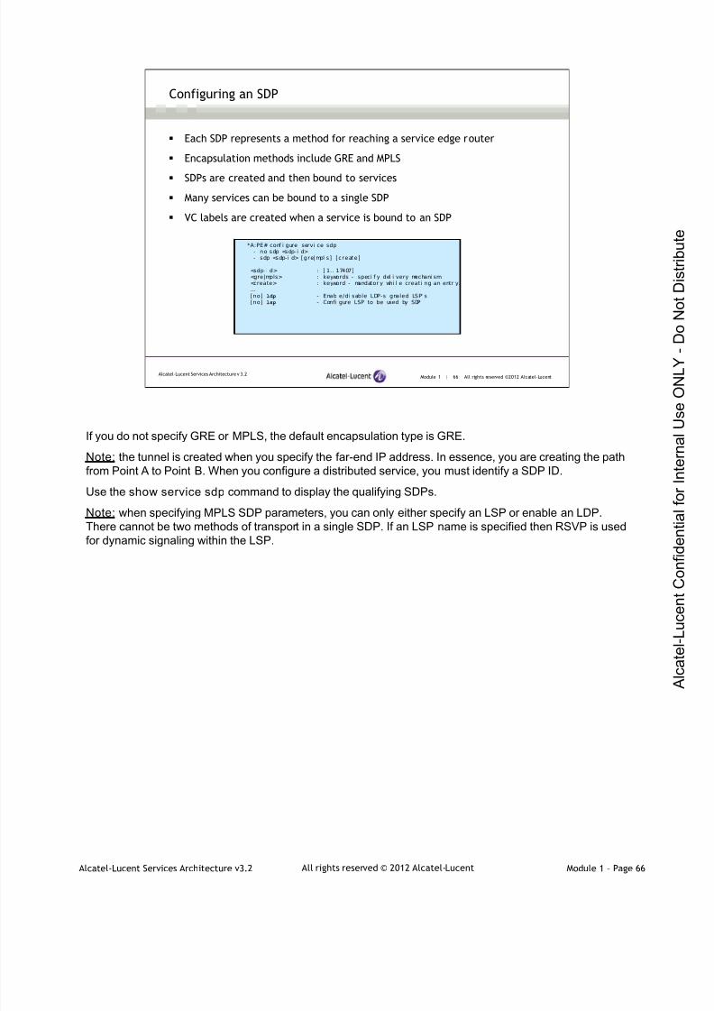
7/21/2019 Services Architecture v3.2 Student Guide Download
http://slidepdf.com/reader/full/services-architecture-v32-student-guide-download 84/429
Alcatel-Lucent Services Architecture v3.2 Module 1 – Page 66All rights reserved © 2012 Alcatel-Lucent
Module 1 | 66 All rights reserved ©2012 Alcatel-LucentAlcatel-Lucent Services Architecture v 3.2
Configuring an SDP
Each SDP represents a method for reaching a service edge router
Encapsulation methods include GRE and MPLS
SDPs are created and then bound to services
Many services can be bound to a single SDP
VC labels are created when a service is bound to an SDP
*A:PE# conf i gure servi ce sdp- no sdp <sdp-i d>- sdp <sdp-i d> [gre|mpl s] [create]
<sdp- i d> : [ 1.. 17407]<gre|mpls> : keywords - speci f y del i very mechani sm<create> : keyword - mandator y whi l e creati ng an entr y.…[no] ldp - Enabl e/di sable LDP-si gnaled LSP' s[no] lsp - Confi gure LSP to be used by SDP
If you do not specify GRE or MPLS, the default encapsulation type is GRE.
Note: the tunnel is created when you specify the far-end IP address. In essence, you are creating the pathfrom Point A to Point B. When you configure a distributed service, you must identify a SDP ID.
Use the show service sdp command to display the qualifying SDPs.
Note: when specifying MPLS SDP parameters, you can only either specify an LSP or enable an LDP.
There cannot be two methods of transport in a single SDP. If an LSP name is specified then RSVP is usedfor dynamic signaling within the LSP.
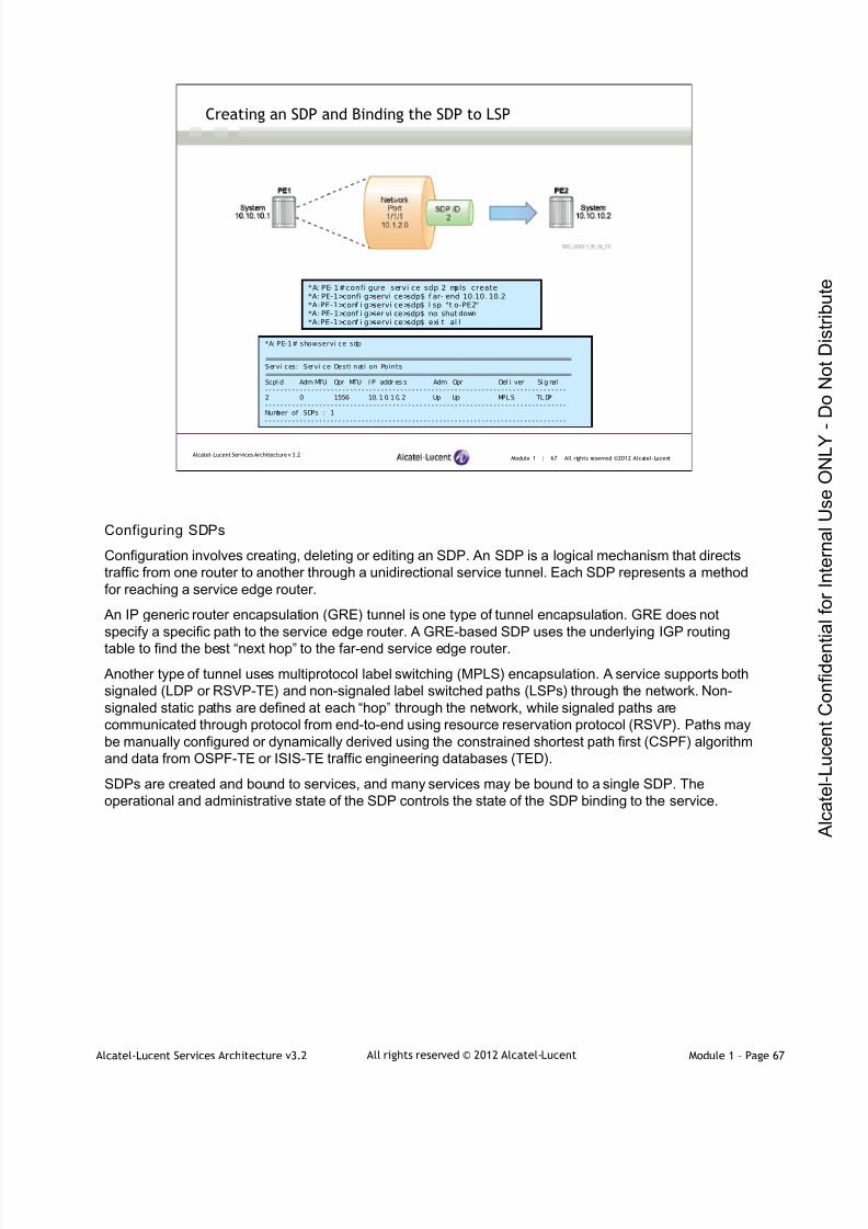
7/21/2019 Services Architecture v3.2 Student Guide Download
http://slidepdf.com/reader/full/services-architecture-v32-student-guide-download 85/429
Alcatel-Lucent Services Architecture v3.2 Module 1 – Page 67All rights reserved © 2012 Alcatel-Lucent
Module 1 | 67 All rights reserved ©2012 Alcatel-LucentAlcatel-Lucent Services Architecture v 3.2
Creating an SDP and Binding the SDP to LSP
*A: PE- 1#confi gure servi ce sdp 2 mpls create*A: PE-1>confi g>servi ce>sdp$ f ar- end 10.10. 10.2*A:PE-1>conf i g>servi ce>sdp$ l sp "t o-PE2"*A: PE- 1>conf i g>ser vi ce>sdp$ no shut down*A:PE-1>conf i g>servi ce>sdp$ exi t al l
*A: PE-1# showservi ce sdp
==============================================================================Servi ces: Servi ce Desti nati on Points==============================================================================SdpI d Adm MTU Opr MTU I P addr es s Adm Opr Del i ver Si g nal- - - - - - - - - - - - - - - - - - - - - - - - - - - - - - - - - - - - - - - - - - - - - - - - - - - - - - - - - - - - - - - - - - - - - - - - - - - - - -2 0 1556 10. 1 0. 1 0. 2 Up Up MPL S TL DP- - - - - - - - - - - - - - - - - - - - - - - - - - - - - - - - - - - - - - - - - - - - - - - - - - - - - - - - - - - - - - - - - - - - - - - - - - - - - -Number of SDPs : 1- - - - - - - - - - - - - - - - - - - - - - - - - - - - - - - - - - - - - - - - - - - - - - - - - - - - - - - - - - - - - - - - - - - - - - - - - - - - - -
Configuring SDPs
Configuration involves creating, deleting or editing an SDP. An SDP is a logical mechanism that directstraffic from one router to another through a unidirectional service tunnel. Each SDP represents a methodfor reaching a service edge router.
An IP generic router encapsulation (GRE) tunnel is one type of tunnel encapsulation. GRE does notspecify a specific path to the service edge router. A GRE-based SDP uses the underlying IGP routing
table to find the best “next hop” to the far-end service edge router.
Another type of tunnel uses multiprotocol label switching (MPLS) encapsulation. A service supports bothsignaled (LDP or RSVP-TE) and non-signaled label switched paths (LSPs) through the network. Non-signaled static paths are defined at each “hop” through the network, while signaled paths arecommunicated through protocol from end-to-end using resource reservation protocol (RSVP). Paths maybe manually configured or dynamically derived using the constrained shortest path first (CSPF) algorithmand data from OSPF-TE or ISIS-TE traffic engineering databases (TED).
SDPs are created and bound to services, and many services may be bound to a single SDP. Theoperational and administrative state of the SDP controls the state of the SDP binding to the service.

7/21/2019 Services Architecture v3.2 Student Guide Download
http://slidepdf.com/reader/full/services-architecture-v32-student-guide-download 86/429
Alcatel-Lucent Services Architecture v3.2 Module 1 – Page 68All rights reserved © 2012 Alcatel-Lucent
Module 1 | 68 All rights reserved ©2012 Alcatel-LucentAlcatel-Lucent Services Architecture v 3.2
*A: PE- 1>conf i g>r out er>mpl s# pat h l oose*A: PE- 1>conf i g>r outer>mpl s>path$ no shutdown*A: PE- 1>conf i g>r outer>mpl s>path$ back*A: PE- 1>conf i g>router>mpl s# l sp t o-PE2*A: PE-1>conf i g>r outer >mpl s>l sp$ t o 10. 10. 10. 2*A: PE-1>conf i g>r outer >mpl s>l sp$ pri mary "l oose"*A: PE-1>conf i g>r outer >mpl s>l sp# no shutdown
Building the Configuration
*A: PE- 1# conf i gure servi ce sdp 2 mpl s create*A: PE- 1>conf i g>servi ce>sdp$ f ar- end 10.10. 10. 2*A: PE- 1>conf i g>servi ce>sdp$ l sp "t o-PE2"*A: PE- 1>conf i g>ser vi ce>sdp$ no shut down*A: PE- 1>conf i g>servi ce>sdp$ exi t al l
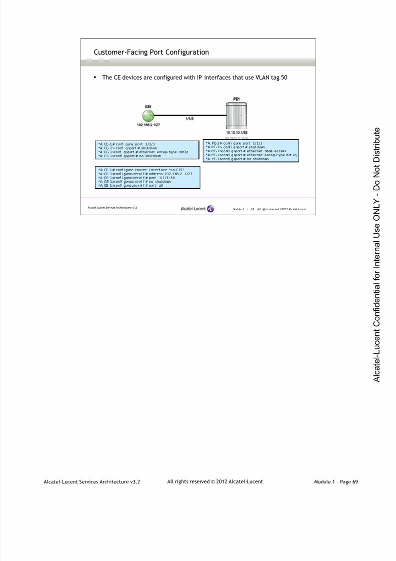
7/21/2019 Services Architecture v3.2 Student Guide Download
http://slidepdf.com/reader/full/services-architecture-v32-student-guide-download 87/429
Alcatel-Lucent Services Architecture v3.2 Module 1 – Page 69All rights reserved © 2012 Alcatel-Lucent
Module 1 | 69 All rights reserved ©2012 Alcatel-LucentAlcatel-Lucent Services Architecture v 3.2
Customer-Facing Port Configuration
The CE devices are configured with IP interfaces that use VLAN tag 50
*A: PE-1# conf i gure port 1/1/3*A:PE-1> conf i g>port # shut down*A:PE-1>conf i g>port # ethernet mode access*A:PE-1>conf i g>port # ethernet encap- t ype dot 1q*A: PE-1>confi g>port # no shutdown
*A: CE-1# conf i gure port 1/1/3*A:CE- 1> conf i g>port # shutdown*A:CE- 1>conf i g>port # ethernet encap- type dot1q*A: CE- 1>confi g>port # no shutdown
*A: CE-1# conf i gure router i nterf ace "t o-CE2"*A:CE- 1>conf i g>router>i f # address 192. 168.2. 1/27*A:CE- 1>conf i g>router>i f # port 1/ 1/3: 50*A: CE- 1>confi g>rout er>i f # no shutdown*A: CE-1>confi g>router>i f # exi t all
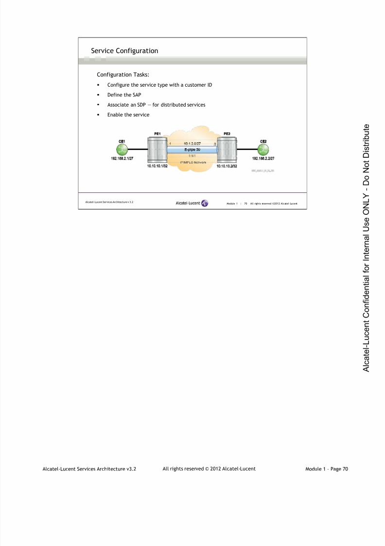
7/21/2019 Services Architecture v3.2 Student Guide Download
http://slidepdf.com/reader/full/services-architecture-v32-student-guide-download 88/429
Alcatel-Lucent Services Architecture v3.2 Module 1 – Page 70All rights reserved © 2012 Alcatel-Lucent
Module 1 | 70 All rights reserved ©2012 Alcatel-LucentAlcatel-Lucent Services Architecture v 3.2
Configuration Tasks:
Configure the service type with a customer ID
Define the SAP
Associate an SDP — for distributed services
Enable the service
Service Configuration

7/21/2019 Services Architecture v3.2 Student Guide Download
http://slidepdf.com/reader/full/services-architecture-v32-student-guide-download 89/429
Alcatel-Lucent Services Architecture v3.2 Module 1 – Page 71All rights reserved © 2012 Alcatel-Lucent
Module 1 | 71 All rights reserved ©2012 Alcatel-LucentAlcatel-Lucent Services Architecture v 3.2
Service Configuration (continued)
Once the service infrastructure has been configured, the distributed service
can be provisioned
The configuration of an epipe is shown below:
*A:PE-1# conf i gure servi ce cust omer 100 create*A:PE-1>conf i g>servi ce>cust$ exi t*A:PE-1# conf i gure servi ce epi pe 50 customer 100 create*A: PE-1>confi g>ser vi ce>epi pe$ sap 1/ 1/3: 50 creat e*A: PE-1>confi g>ser vi ce>epi pe>sap$ back*A:PE-1>conf i g>servi ce>epi pe# spoke-sdp 2:50 create*A: PE-1>confi g>ser vi ce>epi pe>spoke-sdp$ back*A: PE-1>confi g>ser vi ce>epi pe# no shutdown
Once the service infrastructure has been configured, the distributed service can be provisioned.
Configuration of a distributed service is very similar to the local service. The difference is that an SDPbinding is required to signal the service labels and define the transport to the remote router. On the 7750SR, the SDP binding is defined as a spoke or mesh binding. Mesh bindings are used only for VPLSservices. The difference between the two is described later in the course.
The SDP binding specifies both the SDP ID and the VC ID in the format spoke-sdp sdp-id:vc-id. This
identifies the transport tunnel and service tunnel for the pseudowire that is signaled by T-LDP.

7/21/2019 Services Architecture v3.2 Student Guide Download
http://slidepdf.com/reader/full/services-architecture-v32-student-guide-download 90/429
Alcatel-Lucent Services Architecture v3.2 Module 1 – Page 72All rights reserved © 2012 Alcatel-Lucent
Module 1 | 72 All rights reserved ©2012 Alcatel-LucentAlcatel-Lucent Services Architecture v 3.2
Service Verification
Once the service is configured on the remote router with a matching VC ID,
a service label is signaled and the service is up as shown below:
*A: PE-1# show service i d 50 base===============================================================================Servi ce Basic I nformati on===============================================================================Service I d : 50 Vpn I d : 0Servi ce Type : Epi peName : ( Not Speci f i ed)Descri pti on : (Not Speci f i ed)Cust omer I d : 100Last Stat us Change: 02/ 01/2012 11:28: 39Last Mgmt Change : 01/ 31/ 2012 21: 05: 55Admi n State : Up Oper State : UpMTU : 1514Vc Swi tching : Fal seSAP Count : 1 SDP Bi nd Count : 1Per Svc Hashi ng : Di sabl edForce QTag Fwd : Di sabled
- - - - - - - - - - - - - - - - - - - - - - - - - - - - - - - - - - - - - - - - - - - - - - - - - - - - - - - - - - - - - - - - - - - - - - - - - - - - - - -Servi ce Access & Desti nati on Point s- - - - - - - - - - - - - - - - - - - - - - - - - - - - - - - - - - - - - - - - - - - - - - - - - - - - - - - - - - - - - - - - - - - - - - - - - - - - - - -I denti f i er Type AdmMTU OprMTU Adm Opr- - - - - - - - - - - - - - - - - - - - - - - - - - - - - - - - - - - - - - - - - - - - - - - - - - - - - - - - - - - - - - - - - - - - - - - - - - - - - - -sap: 1/1/ 3:50 q-t ag 1518 1518 Up Ups dp: 2: 50 S( 10. 1 0. 1 0. 2 ) Spok 0 1556 Up Up===============================================================================
Once the service infrastructure has been configured, the distributed service can be provisioned.
A pseudowire is bidirectional and is not operational until both ends are successfully signaled.

7/21/2019 Services Architecture v3.2 Student Guide Download
http://slidepdf.com/reader/full/services-architecture-v32-student-guide-download 91/429
Alcatel-Lucent Services Architecture v3.2 Module 1 – Page 73All rights reserved © 2012 Alcatel-Lucent
Module 1 | 73 All rights reserved ©2012 Alcatel-LucentAlcatel-Lucent Services Architecture v 3.2
Service Verification (continued)
A service label is signaled and the CE routers can connect to each other
through the epipe
*A: PE-1# show router l dp bindi ngs f ec-type services
===============================================================================LDP LSR I D: 10.10. 10. 1===============================================================================Legend: U - Label I n Use, N - Label Not I n Use, W - Label Wi thdrawn
S - Status Si gnaled Up, D - Status Si gnaled DownE - Epi pe Service, V - VPLS Service, M - Mi r ror ServiceA - Api pe Service, F - Fpi pe Servi ce, I - I ES Service, R - VPRN serviceP - I pipe Servi ce, WP - Label Wi thdraw Pendi ng, C - Cpipe Servi ce TLV - ( Type, Length: Val ue)
===============================================================================LDP Servi ce FEC 128 Bi ndi ngs=============================================================================== Type VCI d SvcI d SDPI d Peer I ngLbl EgrLbl LMTU RMTU- - - - - - - - - - - - - - - - - - - - - - - - - - - - - - - - - - - - - - - - - - - - - - - - - - - - - - - - - - - - - - - - - - - - - - - - - - - - - - -E-Eth 50 50 2 10. 10.10.2 131068U 131068S 1500 1500- - - - - - - - - - - - - - - - - - - - - - - - - - - - - - - - - - - - - - - - - - - - - - - - - - - - - - - - - - - - - - - - - - - - - - - - - - - - - - -No. of VC Label s: 1
*A:CE- 1# pi ng 192.168. 2. 2PI NG 192. 168. 2. 1 56 data bytes64 bytes f r om192. 168. 2. 1: i cmp_seq=1 tt l =64 ti me=5. 35ms.64 bytes f r om192. 168. 2. 1: i cmp_seq=2 tt l =64 ti me=2. 20ms.64 bytes f r om192. 168. 2. 1: i cmp_seq=3 tt l =64 ti me=2. 26ms.64 bytes f r om192. 168. 2. 1: i cmp_seq=4 tt l =64 ti me=2. 19ms.64 bytes f r om192. 168. 2. 1: i cmp_seq=5 tt l =64 ti me=2. 25ms.
Once the service infrastructure has been configured, the distributed service can be provisioned.
Configuration of a distributed service is very similar to the local service. The difference is that an SDPbinding is required to signal the service labels and define the transport to the remote router. On the 7750SR, the SDP binding is defined as a spoke or mesh binding. Mesh bindings are used only for VPLSservices. The difference between the two is described later in the course.
The SDP binding specifies both the SDP ID and the VC ID in the format spoke sdp sdp-id:vc-id. This
identifies the transport tunnel and service tunnel for the pseudowire that is signaled by T-LDP.
A pseudowire is bidirectional and is not operational until both ends are successfully signaled.

7/21/2019 Services Architecture v3.2 Student Guide Download
http://slidepdf.com/reader/full/services-architecture-v32-student-guide-download 92/429
Alcatel-Lucent Services Architecture v3.2 Module 1 – Page 74All rights reserved © 2012 Alcatel-Lucent
Module 1 | 74 All rights reserved ©2012 Alcatel-LucentAlcatel-Lucent Services Architecture v 3.2
Service Components Summary
Customers (Subscribers)
The customer ID must be associated with the service at the time of
service creation
Service Type
VPRN, VPLS, VPWS or IES
Service Access Point (SAP)
This is the logical entity that serves as the customer’s access to the
service
Service Distribution Points (SDPs)
A method by which a service will connect to the service on another
router
Describes the transport tunnel encapsulation that this service will be
using, such as MPLS/RSVP-TE, MPLS/LDP or IP/GRE
To provision a service on an Alcatel-Lucent router, you must configure the following:
Service — you must define the type of service required.
Service Access Point (SAP) — this is a logical entity that serves as the customer access to theservice.
For a remote VPN you must identify the following:
Service Distribution Points (SDP) — An SDP identifies the other router(s) a service is associatedwith. The SDP also identifies the tunnel encapsulation used by the service tunnel, such as MPLS,or GRE.
Auto-Bind (VPRN only) — This feature is used with MPLS/LDP tunnels and automaticallyprovisions the tunnels.

7/21/2019 Services Architecture v3.2 Student Guide Download
http://slidepdf.com/reader/full/services-architecture-v32-student-guide-download 93/429
Alcatel-Lucent Services Architecture v3.2 Module 1 – Page 75All rights reserved © 2012 Alcatel-Lucent
Module 1 | 75 All rights reserved ©2012 Alcatel-LucentAlcatel-Lucent Services Architecture v 3.2
Module Summary
SAPs, services and SDPs work together to provide logical service-level
connectivity
SDPs provide links to service tunnels, which are provisioned with a setencapsulation type of either MPLS or GRE
SDPs provide the T-LDP session
Matching VC IDs are used to signal the service labels
SAPs can only be configured on access ports, while SDPs can only be
created on network ports
Although many of the service component identifiers have local
significance, the VC ID has point-to-point significance and must be unique
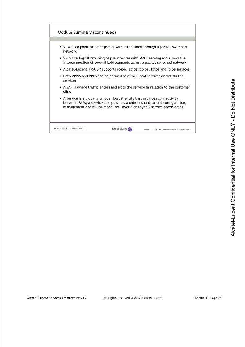
7/21/2019 Services Architecture v3.2 Student Guide Download
http://slidepdf.com/reader/full/services-architecture-v32-student-guide-download 94/429
Alcatel-Lucent Services Architecture v3.2 Module 1 – Page 76All rights reserved © 2012 Alcatel-Lucent
Module 1 | 76 All rights reserved ©2012 Alcatel-LucentAlcatel-Lucent Services Architecture v 3.2
Module Summary (continued)
VPWS is a point-to-point pseudowire established through a packet-switched
network
VPLS is a logical grouping of pseudowires with MAC learning and allows the
interconnection of several LAN segments across a packet-switched network
Alcatel-Lucent 7750 SR supports epipe, apipe, cpipe, fpipe and ipipe services
Both VPWS and VPLS can be defined as either local services or distributed
services
A SAP is where traffic enters and exits the service in relation to the customer
sites
A service is a globally unique, logical entity that provides connectivity
between SAPs; a service also provides a uniform, end-to-end configuration,
management and billing model for Layer 2 or Layer 3 service provisioning

7/21/2019 Services Architecture v3.2 Student Guide Download
http://slidepdf.com/reader/full/services-architecture-v32-student-guide-download 95/429
Alcatel-Lucent Services Architecture v3.2 Module 1 – Page 77All rights reserved © 2012 Alcatel-Lucent
Module 1 | 77 All rights reserved ©2012 Alcatel-LucentAlcatel-Lucent Services Architecture v 3.2
Module Summary (continued)
When a service spans more than one router, it uses SDPs to direct traffic
to another router; traffic is transported by a transport tunnel through a
service tunnel
To provision a service, you must configure the following: customer,
service type, SAP and SDP
The following are transport tunnel encapsulation options: MPLS/RSVP-
TE, MPLS/LDP or IP/GRE
To provision a service, a customer ID must be associated with the
service when it is created
The following are SAP identifiers: physical Ethernet port or POS port and
channel, encapsulation type and encapsulation identifier
SDPs are locally unique and normally use the system IP address to
identify far-end destinations

7/21/2019 Services Architecture v3.2 Student Guide Download
http://slidepdf.com/reader/full/services-architecture-v32-student-guide-download 96/429
Alcatel-Lucent Services Architecture v3.2 Module 1 – Page 78All rights reserved © 2012 Alcatel-Lucent
Module 1 | 78 All rights reserved ©2012 Alcatel-LucentAlcatel-Lucent Services Architecture v 3.2
Module Summary (continued)
SDP is not specific to one service; many services can use the same SDP
A service label is used to distinguish between multiple services that use
the same SDP
VPLS and VPWS service labels are signaled using T-LDP
VPRN service label is signaled by MP-BGP based on RFC 4364
An SAP is associated with a single service and can only be configured on
an access port
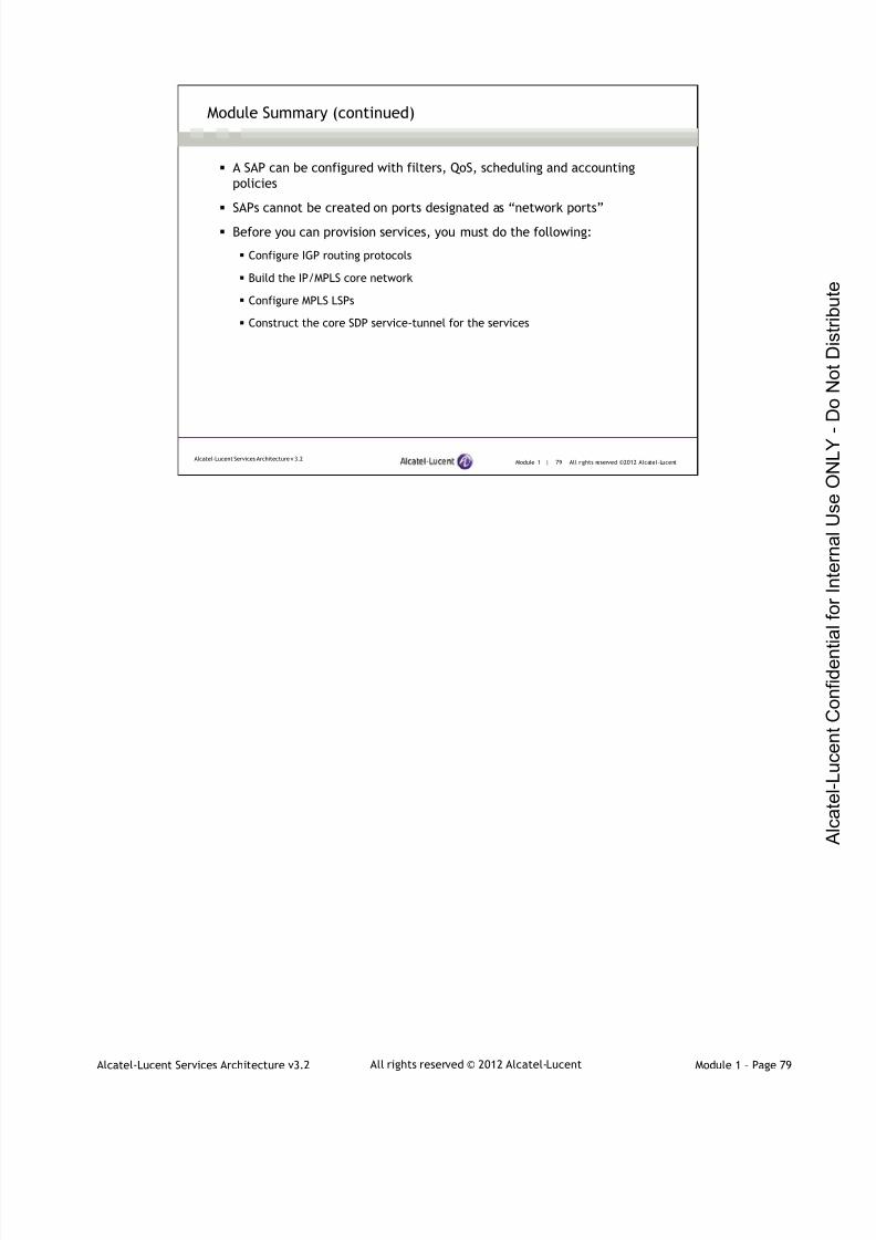
7/21/2019 Services Architecture v3.2 Student Guide Download
http://slidepdf.com/reader/full/services-architecture-v32-student-guide-download 97/429
Alcatel-Lucent Services Architecture v3.2 Module 1 – Page 79All rights reserved © 2012 Alcatel-Lucent
Module 1 | 79 All rights reserved ©2012 Alcatel-LucentAlcatel-Lucent Services Architecture v 3.2
Module Summary (continued)
A SAP can be configured with filters, QoS, scheduling and accounting
policies
SAPs cannot be created on ports designated as “network ports”
Before you can provision services, you must do the following:
Configure IGP routing protocols
Build the IP/MPLS core network
Configure MPLS LSPs
Construct the core SDP service-tunnel for the services
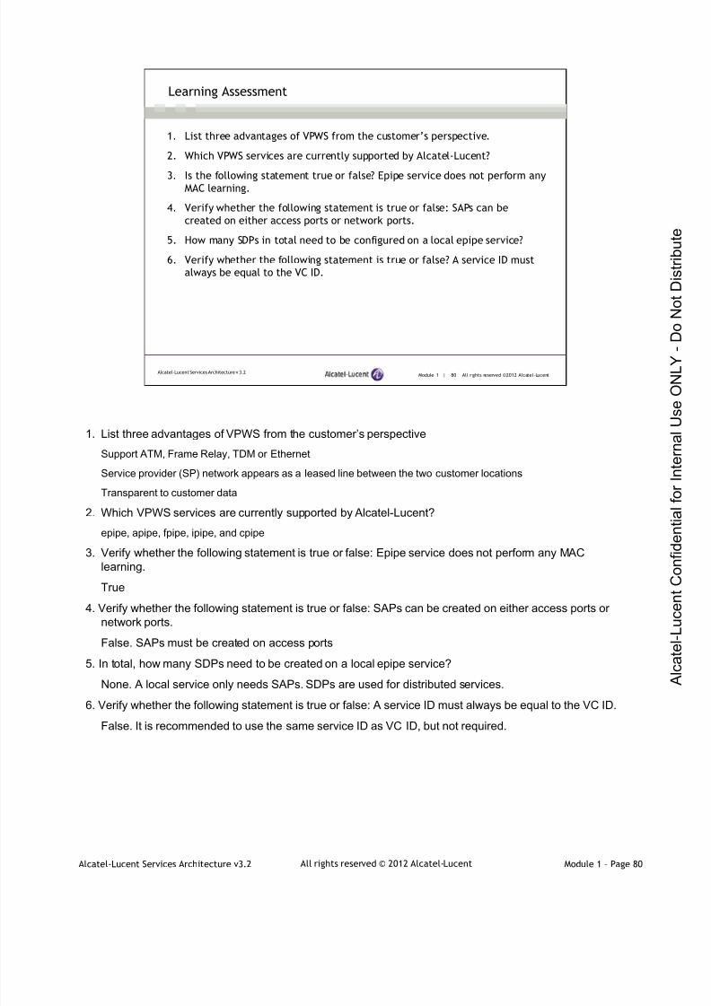
7/21/2019 Services Architecture v3.2 Student Guide Download
http://slidepdf.com/reader/full/services-architecture-v32-student-guide-download 98/429
Alcatel-Lucent Services Architecture v3.2 Module 1 – Page 80All rights reserved © 2012 Alcatel-Lucent
Module 1 | 80 All rights reserved ©2012 Alcatel-LucentAlcatel-Lucent Services Architecture v 3.2
Learning Assessment
1. List three advantages of VPWS from the customer’s perspective.
2. Which VPWS services are currently supported by Alcatel-Lucent?
3. Is the following statement true or false? Epipe service does not perform anyMAC learning.
4. Verify whether the following statement is true or false: SAPs can be
created on either access ports or network ports.
5. How many SDPs in total need to be configured on a local epipe service?
6. Verify whether the following statement is true or false? A service ID must
always be equal to the VC ID.
1. List three advantages of VPWS from the customer’s perspective
Support ATM, Frame Relay, TDM or Ethernet
Service provider (SP) network appears as a leased line between the two customer locations
Transparent to customer data
2. Which VPWS services are currently supported by Alcatel-Lucent?
epipe, apipe, fpipe, ipipe, and cpipe
3. Verify whether the following statement is true or false: Epipe service does not perform any MAClearning.
True
4. Verify whether the following statement is true or false: SAPs can be created on either access ports ornetwork ports.
False. SAPs must be created on access ports
5. In total, how many SDPs need to be created on a local epipe service?
None. A local service only needs SAPs. SDPs are used for distributed services.
6. Verify whether the following statement is true or false: A service ID must always be equal to the VC ID.
False. It is recommended to use the same service ID as VC ID, but not required.
7/21/2019 Services Architecture v3.2 Student Guide Download
http://slidepdf.com/reader/full/services-architecture-v32-student-guide-download 99/429
Alcatel-Lucent Services Architecture v3.2 Module 1 – Page 81All rights reserved © 2012 Alcatel-Lucent
Module 1 | 81 All rights reserved ©2012 Alcatel-LucentAlcatel-Lucent Services Architecture v 3.2
Learning Assessment (continued)
7. Based on best practice, place the correct letter on each line:
SAP ID ______ a. Local significance
SDP ID ______ b. Global significance
VC ID ______ c. Point-to-point significance
Service ID ______
Customer ID ______
8. Fill in the blank: A SAP can only be configured on a port which has been
configured as an ____________ port.
9. Fill in the blank: The default configuration for a port is ______.
10. Verify whether the following statement is true or false: Service tunnels
are unidirectional.
11. Verify whether the following statement is true or false: A SAP can never
be associated with more than one service.
7. Based on best practice, place the correct letter on each line:
SAP ID A
SDP ID A
VC ID C
Service ID B
Customer ID B
8. Fill in the blank: A SAP can only be configured on a port which has been configured as an access port.
9. Fill in the blank: The default configuration for a port is network.
10.Verify whether the following statement is true or false: Service tunnels are unidirectional.
True
11. Verify whether the following statement is true or false: A SAP can never be associated with more thanone service.
True
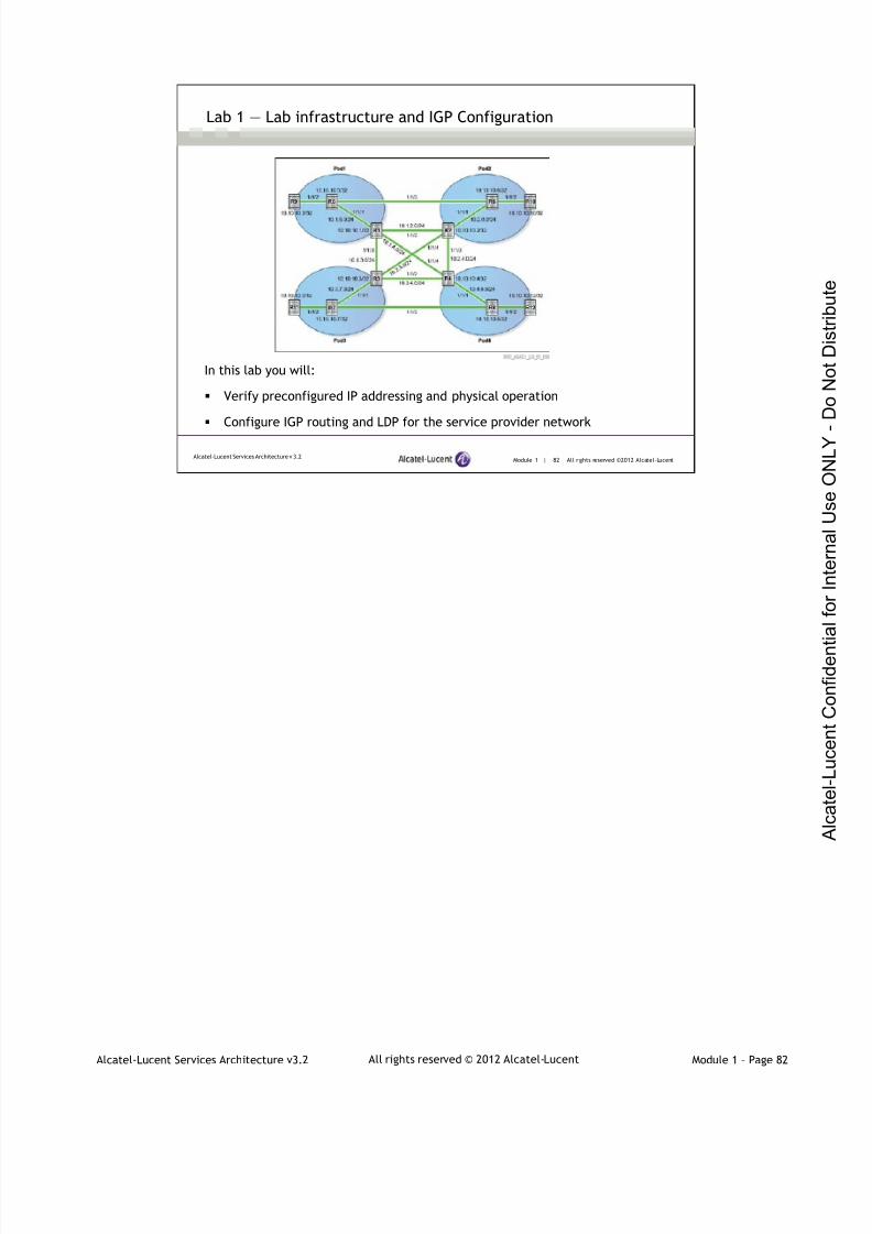
7/21/2019 Services Architecture v3.2 Student Guide Download
http://slidepdf.com/reader/full/services-architecture-v32-student-guide-download 100/429
Alcatel-Lucent Services Architecture v3.2 Module 1 – Page 82All rights reserved © 2012 Alcatel-Lucent
Module 1 | 82 All rights reserved ©2012 Alcatel-LucentAlcatel-Lucent Services Architecture v 3.2
Lab 1 ― Lab infrastructure and IGP Configuration
In this lab you will:
Verify preconfigured IP addressing and physical operation
Configure IGP routing and LDP for the service provider network

7/21/2019 Services Architecture v3.2 Student Guide Download
http://slidepdf.com/reader/full/services-architecture-v32-student-guide-download 101/429
www.alcatel-lucent.com/src
3FL-30636-AAAA-ZZZZA Edition 01

7/21/2019 Services Architecture v3.2 Student Guide Download
http://slidepdf.com/reader/full/services-architecture-v32-student-guide-download 102/429
Alcatel-Lucent Services Architecture v3.2 All rights reserved © 2012 Alcatel-Lucent Module 2 – Page 1
Alcatel-Lucent Services Architecture
Module 2 — Virtual Private Wire Services
7/21/2019 Services Architecture v3.2 Student Guide Download
http://slidepdf.com/reader/full/services-architecture-v32-student-guide-download 103/429
Alcatel-Lucent Services Architecture v3.2 All rights reserved © 2012 Alcatel-Lucent Module 2 – Page 2
Module 2 | 2 A ll r ights re se rved ©2012 Alcate l-LucentAlcatel-Lucent Services Architecture v3.2
Module Objectives
After successfully completing this module, you will be able to:
Examine the details of E-pipe configuration and verification
Describe the other VPWS types available (apipe, fpipe, cpipe,ipipe)
Recognize the interworking capabilities of the different VPWS
This course is part of the Alcatel-Lucent Service Routing Certification (SRC) Program. Visit the Alcatel-
Lucent web site at www.alcatel-lucent.com/src for more information on the SRC program.
To locate additional information related to the topics presented in this manual, refer to the following:
Technical Practices for the specific product
Internet Standards documentation such as protocol standards bodies, RFCs and IETF drafts
Technical support pages of the Alcatel-Lucent web site located at http://www.alcatel-lucent.com/support
This module defines and identifies the VPWS services implemented by Alcatel-Lucent. In this module, you
will be introduced to the process used by Alcatel-Lucent in the implementation of VPWS, including epipe,
apipe, fpipe and cpipe services. This module provides information on these Layer 2 point-to-point services
and how customer data is encapsulated and transported across a service provider’s IP or MPLS network.
Epipe, apipe, fpipe and cpipe are identified as completely transparent to the subscriber’s data and
protocols.

7/21/2019 Services Architecture v3.2 Student Guide Download
http://slidepdf.com/reader/full/services-architecture-v32-student-guide-download 104/429
Alcatel-Lucent Services Architecture v3.2 All rights reserved © 2012 Alcatel-Lucent Module 2 – Page 3
Alcatel-Lucent Services Architecture
Section 1 — Epipe
7/21/2019 Services Architecture v3.2 Student Guide Download
http://slidepdf.com/reader/full/services-architecture-v32-student-guide-download 105/429
Alcatel-Lucent Services Architecture v3.2 All rights reserved © 2012 Alcatel-Lucent Module 2 – Page 4
Module 2 | 4 A ll r ights re se rved ©2012 Alcate l-LucentAlcatel-Lucent Services Architecture v3.2
Section Objectives
After successfully completing this section, you will be able to:
Define the different types of VPWS available
Describe the different types of Ethernet SAP encapsulation (null,
dot1q, qinq) and the concept of VLAN tag
Differentiate between the supported SAP values (default, null, etc)
Explain the use of Ethertype value in identifying tagged frames
Identify the types of MTUs to be considered when designing a layer 2
service (SAP MTU, Service and VC MTU, SDP MTU, network port MTU)

7/21/2019 Services Architecture v3.2 Student Guide Download
http://slidepdf.com/reader/full/services-architecture-v32-student-guide-download 106/429
Alcatel-Lucent Services Architecture v3.2 All rights reserved © 2012 Alcatel-Lucent Module 2 – Page 5
Module 2 | 5 A ll r ights re se rved ©2012 Alcate l-LucentAlcatel-Lucent Services Architecture v3.2
Section Objectives (continued)
Explain the relationship between the different types of MTUs
Describe the difference between VC-types for epipe: tagged mode(VLAN) versus raw mode (Ether)
Identify the different possible combination of frame transmission for
null, dot1q, and qinq encapsulation SAP with different egress
encapsulation
Configure and verify a distributed epipe service
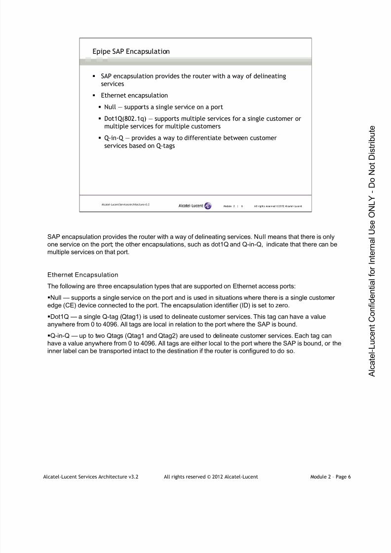
7/21/2019 Services Architecture v3.2 Student Guide Download
http://slidepdf.com/reader/full/services-architecture-v32-student-guide-download 107/429
Alcatel-Lucent Services Architecture v3.2 All rights reserved © 2012 Alcatel-Lucent Module 2 – Page 6
Module 2 | 6 A ll r ights re se rved ©2012 Alcate l-LucentAlcatel-Lucent Services Architecture v3.2
Epipe SAP Encapsulation
SAP encapsulation provides the router with a way of delineating
services
Ethernet encapsulation
Null — supports a single service on a port
Dot1Q(802.1q) — supports multiple services for a single customer or
multiple services for multiple customers
Q-in-Q — provides a way to differentiate between customer
services based on Q-tags
SAP encapsulation provides the router with a way of delineating services. Null means that there is only
one service on the port; the other encapsulations, such as dot1Q and Q-in-Q, indicate that there can be
multiple services on that port.
Ethernet Encapsulation
The following are three encapsulation types that are supported on Ethernet access ports:
Null — supports a single service on the port and is used in situations where there is a single customer
edge (CE) device connected to the port. The encapsulation identifier (ID) is set to zero.
Dot1Q — a single Q-tag (Qtag1) is used to delineate customer services. This tag can have a value
anywhere from 0 to 4096. All tags are local in relation to the port where the SAP is bound.
Q-in-Q — up to two Qtags (Qtag1 and Qtag2) are used to delineate customer services. Each tag can
have a value anywhere from 0 to 4096. All tags are either local to the port where the SAP is bound, or the
inner label can be transported intact to the destination if the router is configured to do so.

7/21/2019 Services Architecture v3.2 Student Guide Download
http://slidepdf.com/reader/full/services-architecture-v32-student-guide-download 108/429
Alcatel-Lucent Services Architecture v3.2 All rights reserved © 2012 Alcatel-Lucent Module 2 – Page 7
Module 2 | 7 A ll r ights re se rved ©2012 Alcate l-LucentAlcatel-Lucent Services Architecture v3.2
Epipe SAP Encapsulation (continued)
Encapsulation type VLAN tags SAP syntax
null 0port
Example - Port 1/1/1
dot1q 1port:tag
Example - port 1/1/1:10
qinq 2port:outer-tag.inner-tag
Example - port 1/1/1:10.100
VLAN tag is used to determine which service the frame belongs to
Multiple SAPs can be defined on a single port for different services
The Alcatel-Lucent 7750 SR implementation of an epipe is based on RFC 4448 (Encapsulation Methods
for Transport of Ethernet over MPLS Networks).
IEEE 802.1Q, or VLAN Tagging, is a networking standard written by the IEEE 802.1 workgroup. It allows
multiple-bridged networks to transparently share the same physical network link without leakage
of information between networks. IEEE 802.1Q — also known as dot1q — is commonly used to refer to
the encapsulation protocol used to implement this mechanism over Ethernet networks.
When a VLAN tag is specified as part of the encapsulation, it is considered to be service delimiting. Thismeans that the VLAN tag is used to determine which service the frame belongs to. For example, if a SAP
is created in a service as 1/1/1:10, all frames arriving at port 1/1/1 with VLAN tag 10 belong to the service.
All other frames do not.
Using service delimiting VLAN tags, multiple SAPs can be defined on a single port for different services.
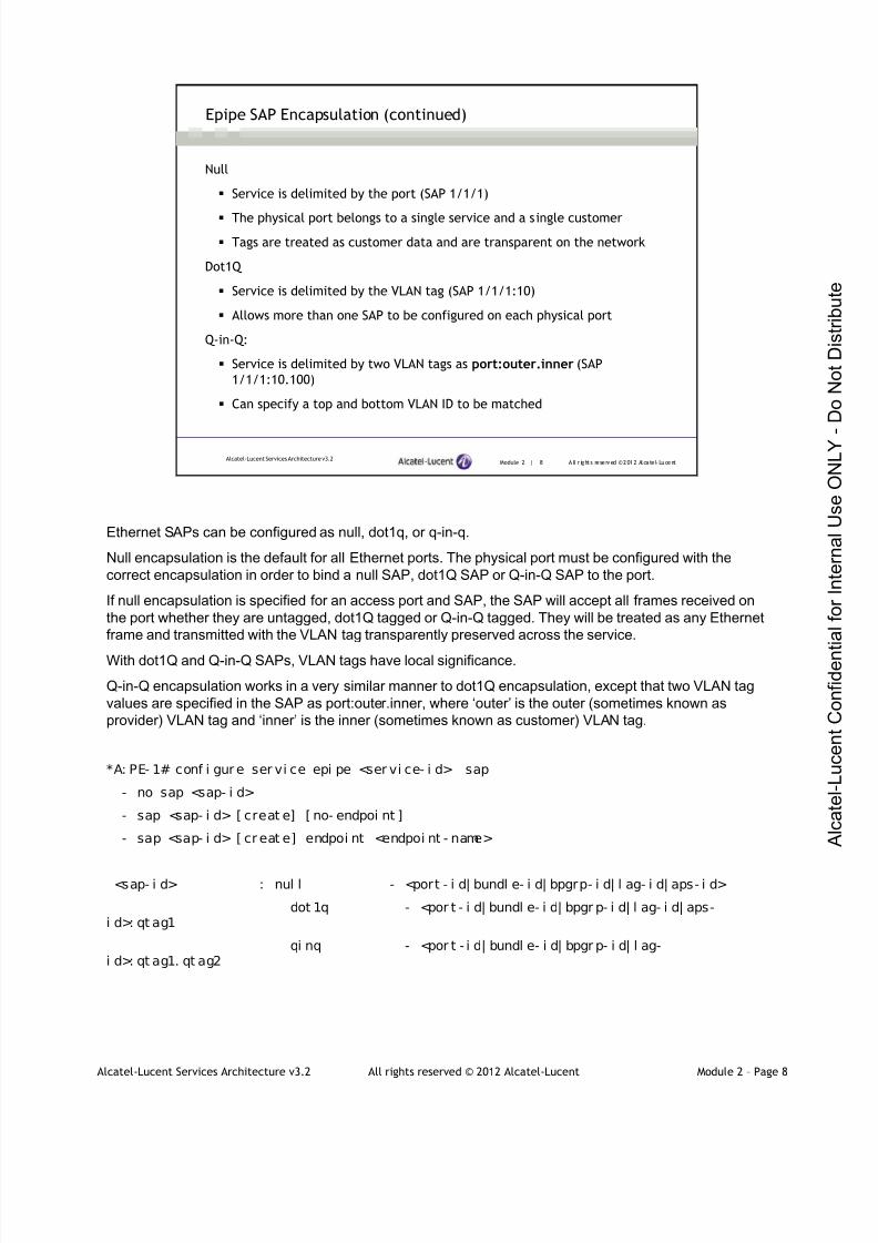
7/21/2019 Services Architecture v3.2 Student Guide Download
http://slidepdf.com/reader/full/services-architecture-v32-student-guide-download 109/429
Alcatel-Lucent Services Architecture v3.2 All rights reserved © 2012 Alcatel-Lucent Module 2 – Page 8
Module 2 | 8 A ll r ights re se rved ©2012 Alcate l-LucentAlcatel-Lucent Services Architecture v3.2
Epipe SAP Encapsulation (continued)
Null
Service is delimited by the port (SAP 1/1/1)
The physical port belongs to a single service and a single customer
Tags are treated as customer data and are transparent on the network
Dot1Q
Service is delimited by the VLAN tag (SAP 1/1/1:10)
Allows more than one SAP to be configured on each physical port
Q-in-Q:
Service is delimited by two VLAN tags as port:outer.inner (SAP
1/1/1:10.100)
Can specify a top and bottom VLAN ID to be matched
Ethernet SAPs can be configured as null, dot1q, or q-in-q.
Null encapsulation is the default for all Ethernet ports. The physical port must be configured with the
correct encapsulation in order to bind a null SAP, dot1Q SAP or Q-in-Q SAP to the port.
If null encapsulation is specified for an access port and SAP, the SAP will accept all frames received on
the port whether they are untagged, dot1Q tagged or Q-in-Q tagged. They will be treated as any Ethernet
frame and transmitted with the VLAN tag transparently preserved across the service.
With dot1Q and Q-in-Q SAPs, VLAN tags have local significance.
Q-in-Q encapsulation works in a very similar manner to dot1Q encapsulation, except that two VLAN tag
values are specified in the SAP as port:outer.inner, where ‘outer’ is the outer (sometimes known as
provider) VLAN tag and ‘inner’ is the inner (sometimes known as customer) VLAN tag.
*A: PE- 1# conf i gur e ser vi ce epi pe <ser vi ce- i d> sap
- no sap <sap- i d>
- sap <sap- i d> [ creat e] [ no- endpoi nt ]
- sap <sap- i d> [ cr eat e] endpoi nt <endpoi nt - name>
<sap- i d> : nul l - <port - i d| bundl e- i d| bpgrp- i d| l ag- i d| aps- i d>
dot 1q - <por t - i d| bundl e- i d| bpgr p- i d| l ag- i d| aps-i d>: qt ag1
qi nq - <por t - i d| bundl e- i d| bpgr p- i d| l ag-i d>: qt ag1. qt ag2
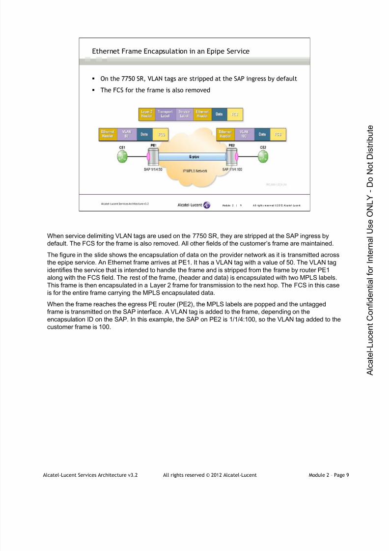
7/21/2019 Services Architecture v3.2 Student Guide Download
http://slidepdf.com/reader/full/services-architecture-v32-student-guide-download 110/429
Alcatel-Lucent Services Architecture v3.2 All rights reserved © 2012 Alcatel-Lucent Module 2 – Page 9
Module 2 | 9 A ll r ights re se rved ©2012 Alcate l-LucentAlcatel-Lucent Services Architecture v3.2
Ethernet Frame Encapsulation in an Epipe Service
On the 7750 SR, VLAN tags are stripped at the SAP ingress by default
The FCS for the frame is also removed
When service delimiting VLAN tags are used on the 7750 SR, they are stripped at the SAP ingress by
default. The FCS for the frame is also removed. All other fields of the customer’s frame are maintained.
The figure in the slide shows the encapsulation of data on the provider network as it is transmitted across
the epipe service. An Ethernet frame arrives at PE1. It has a VLAN tag with a value of 50. The VLAN tag
identifies the service that is intended to handle the frame and is stripped from the frame by router PE1
along with the FCS field. The rest of the frame, (header and data) is encapsulated with two MPLS labels.
This frame is then encapsulated in a Layer 2 frame for transmission to the next hop. The FCS in this case
is for the entire frame carrying the MPLS encapsulated data.
When the frame reaches the egress PE router (PE2), the MPLS labels are popped and the untagged
frame is transmitted on the SAP interface. A VLAN tag is added to the frame, depending on the
encapsulation ID on the SAP. In this example, the SAP on PE2 is 1/1/4:100, so the VLAN tag added to the
customer frame is 100.

7/21/2019 Services Architecture v3.2 Student Guide Download
http://slidepdf.com/reader/full/services-architecture-v32-student-guide-download 111/429
Alcatel-Lucent Services Architecture v3.2 All rights reserved © 2012 Alcatel-Lucent Module 2 – Page 10
Module 2 | 10 A ll r ights re se rved ©2012 A lcatel -LucentAlcatel-Lucent Services Architecture v3.2
Special SAP Values - dot1q
Default SAP (port:*)
Receives all untagged frames and any frames with tag values that arenot used as a service-delimiting value on another SAP
VLAN tags are not stripped and are passed transparently
Example – sap 1/1/3:*
Null SAP (port:0)
Receives all untagged frames and all frames with a VLAN tag of 0
Example – sap 1/1/3:0
Null SAP and default SAP are mutually exclusive on a port
VLAN tags do not have to be service delimiting and can be passed transparently. Similar to the behavior in
null encapsulation, in a case where a SAP is defined as a dot1Q service, delimiting SAP and a Q-in-Q
frame is received at the port. If the outer tag matches the value in the SAP, it will be stripped and the
frame transmitted over the service with the inner tag transparently maintained. If the outer tag does not
match the SAP value, the frame is ignored by the service.
The default SAP can be used in a situation where it is desired to pass all customer VLAN tagged frames
transparently, but capture some specific traffic for another purpose.
The null SAP is used when it is desirable to capture untagged traffic in another service. Use of the null
SAP and default SAP are mutually exclusive on a port - if one is defined in a service the other cannot be
used.
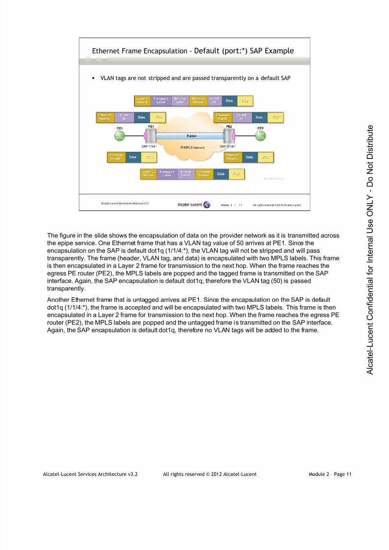
7/21/2019 Services Architecture v3.2 Student Guide Download
http://slidepdf.com/reader/full/services-architecture-v32-student-guide-download 112/429
Alcatel-Lucent Services Architecture v3.2 All rights reserved © 2012 Alcatel-Lucent Module 2 – Page 11
Module 2 | 11 A ll r ights re se rved ©2012 A lcatel -LucentAlcatel-Lucent Services Architecture v3.2
Ethernet Frame Encapsulation - Default (port:*) SAP Example
VLAN tags are not stripped and are passed transparently on a default SAP
The figure in the slide shows the encapsulation of data on the provider network as it is transmitted across
the epipe service. One Ethernet frame that has a VLAN tag value of 50 arrives at PE1. Since the
encapsulation on the SAP is default dot1q (1/1/4:*), the VLAN tag will not be stripped and will pass
transparently. The frame (header, VLAN tag, and data) is encapsulated with two MPLS labels. This frame
is then encapsulated in a Layer 2 frame for transmission to the next hop. When the frame reaches the
egress PE router (PE2), the MPLS labels are popped and the tagged frame is transmitted on the SAP
interface. Again, the SAP encapsulation is default dot1q, therefore the VLAN tag (50) is passed
transparently.
Another Ethernet frame that is untagged arrives at PE1. Since the encapsulation on the SAP is default
dot1q (1/1/4:*), the frame is accepted and will be encapsulated with two MPLS labels. This frame is then
encapsulated in a Layer 2 frame for transmission to the next hop. When the frame reaches the egress PE
router (PE2), the MPLS labels are popped and the untagged frame is transmitted on the SAP interface.
Again, the SAP encapsulation is default dot1q, therefore no VLAN tags will be added to the frame.
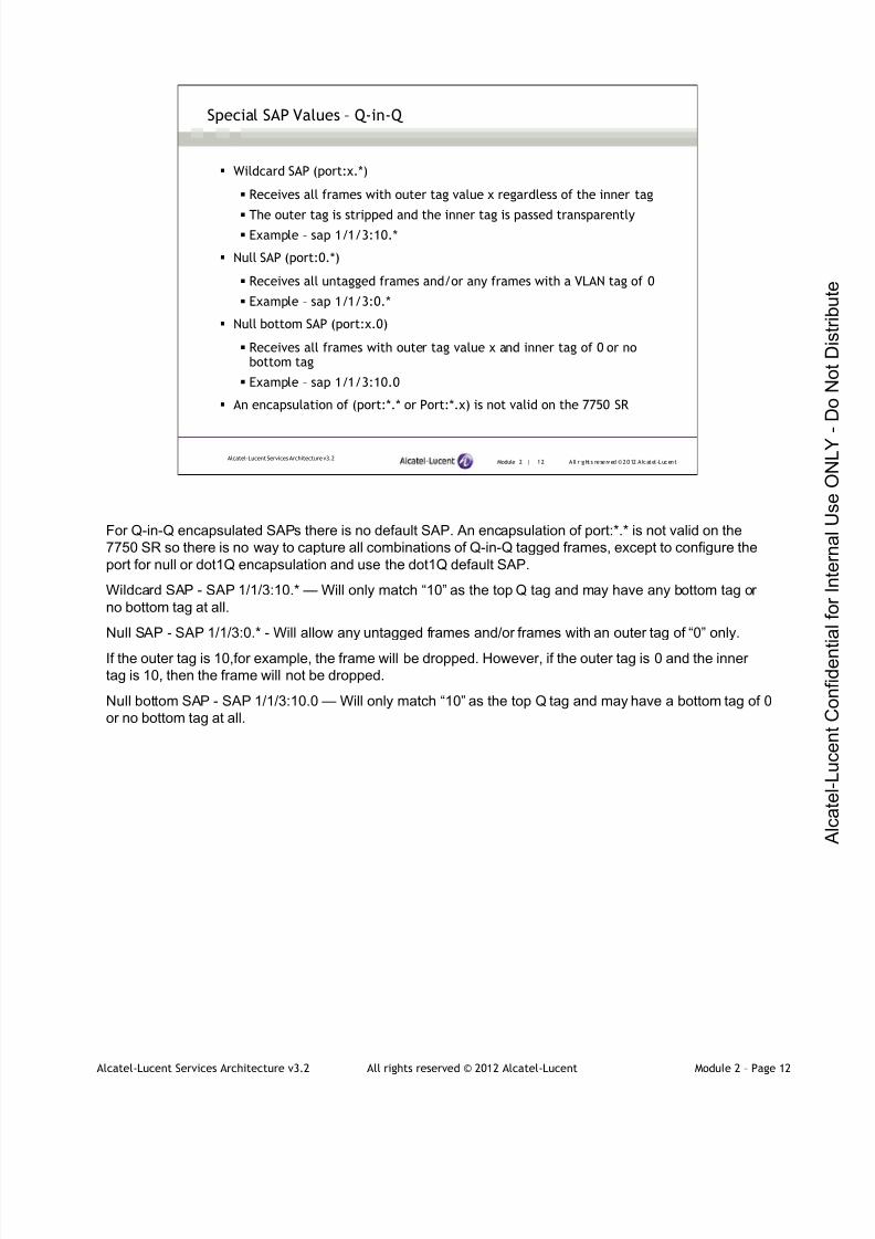
7/21/2019 Services Architecture v3.2 Student Guide Download
http://slidepdf.com/reader/full/services-architecture-v32-student-guide-download 113/429
Alcatel-Lucent Services Architecture v3.2 All rights reserved © 2012 Alcatel-Lucent Module 2 – Page 12
Module 2 | 12 A ll r ights re se rved ©2012 A lcatel -LucentAlcatel-Lucent Services Architecture v3.2
Special SAP Values – Q-in-Q
Wildcard SAP (port:x.*)
Receives all frames with outer tag value x regardless of the inner tag
The outer tag is stripped and the inner tag is passed transparently
Example – sap 1/1/3:10.*
Null SAP (port:0.*)
Receives all untagged frames and/or any frames with a VLAN tag of 0
Example – sap 1/1/3:0.*
Null bottom SAP (port:x.0)
Receives all frames with outer tag value x and inner tag of 0 or nobottom tag
Example – sap 1/1/3:10.0
An encapsulation of (port:*.* or Port:*.x) is not valid on the 7750 SR
For Q-in-Q encapsulated SAPs there is no default SAP. An encapsulation of port:*.* is not valid on the
7750 SR so there is no way to capture all combinations of Q-in-Q tagged frames, except to configure the
port for null or dot1Q encapsulation and use the dot1Q default SAP.
Wildcard SAP - SAP 1/1/3:10.* — Will only match “10” as the top Q tag and may have any bottom tag or
no bottom tag at all.
Null SAP - SAP 1/1/3:0.* - Will allow any untagged frames and/or frames with an outer tag of “0” only.
If the outer tag is 10,for example, the frame will be dropped. However, if the outer tag is 0 and the inner
tag is 10, then the frame will not be dropped.
Null bottom SAP - SAP 1/1/3:10.0 — Will only match “10” as the top Q tag and may have a bottom tag of 0
or no bottom tag at all.

7/21/2019 Services Architecture v3.2 Student Guide Download
http://slidepdf.com/reader/full/services-architecture-v32-student-guide-download 114/429
Alcatel-Lucent Services Architecture v3.2 All rights reserved © 2012 Alcatel-Lucent Module 2 – Page 13
Module 2 | 13 A ll r ights re se rved ©2012 A lcatel -LucentAlcatel-Lucent Services Architecture v3.2
Ethernet Frame Encapsulation - Null SAP (port:0.*) Example
Null SAP will pass untagged frames, frames with one VLAN tag of 0, or
double-tags where the outer VLAN tag is 0
A VLAN tag received on a SAP port is considered service delimiting if it matches the encapsulation on the
SAP port. The figure in the slide shows the encapsulation of data on the customer network as it is
transmitted across the epipe service. Three frames arrive at a null SAP on PE1.
The first Ethernet frame is untagged; null SAP will accept the frame and the frame (header, data) is
encapsulated with two MPLS labels. This frame is then encapsulated in a Layer 2 frame for transmission
to the next hop. When the frame reaches the egress PE router (PE2), the MPLS labels are popped and
the untagged frame is transmitted on the SAP interface. The SAP encapsulation on PE2 is null, therefore
no tags are added and the frame is passed transparently.
The second frame has an outer VLAN tag of 0, and no inner VLAN tag. SAP 1/1/4:0.* will accept the frame
and service delimiting tag of 0 is stripped before the frame is encapsulated with the two MPLS labels. On
PE2 the frame will be passed transparently as in the first case.
The third frame has an outer tag of 0 and an inner tag of 10. The null SAP 1/1/4:0.* will accept the frame,
the service outer tag is stripped and the inner tag (10) is passed transparently. The frame (header, VLAN
tag 10, and data) will be encapsulated with the two MPLS labels. When the tagged frame reaches the PE-
2, the MPLS labels are popped and the tagged frame is transmitted on the null SAP interface. No other
VLAN tags will be added to the frame.

7/21/2019 Services Architecture v3.2 Student Guide Download
http://slidepdf.com/reader/full/services-architecture-v32-student-guide-download 115/429
Alcatel-Lucent Services Architecture v3.2 All rights reserved © 2012 Alcatel-Lucent Module 2 – Page 14
Module 2 | 14 A ll r ights re se rved ©2012 A lcatel -LucentAlcatel-Lucent Services Architecture v3.2
Ethertype Values
IEEE 802.1Q specifies a hex value of 0x8100 to be used in the Ethertype
field to indentify the frame as a tagged frame
On the 7750 SR, Ethertype can be configured as follows:
For multivendor interoperability, frames with non-matching Ethertypes are
treated as untagged
*A:PE-1# configure port 1/1/1
*A: PE-1>confi g>port # ethernet dot1q-etype ?
- dot1q-etype <0x0600.. 0xf ff f>
- no dot1q-etype
<0x0600. . 0xf f f f > : [1536. . 65535] - accepts in deci mal or hex
IEEE 802.1Q specifies a hex value of 0x8100 to be used in the Ethertype field to indentify the frame as a
tagged frame. This value is also used for the Ethertype value in the inner VLAN tag for Q-in-Q
encapsulation. However, some older switches use proprietary Ethertype values to identify the VLAN tag. If
the 7750 SR in its default configuration receives a tagged frame with an Ethertype value other than
0x8100, it is simply treated as an untagged frame.
It is possible to configure the port on the 7750 SR to use a different Ethertype value to identify tagged
frames. A different value can be specified for either the outer tag (dot1Q Ethertype) or the inner tag (Q-in-
Q Ethertype), or both.
When the Ethertype value is changed, any frame with an Ethertype that does not match the configured
value is treated as an untagged frame.

7/21/2019 Services Architecture v3.2 Student Guide Download
http://slidepdf.com/reader/full/services-architecture-v32-student-guide-download 116/429
Alcatel-Lucent Services Architecture v3.2 All rights reserved © 2012 Alcatel-Lucent Module 2 – Page 15
Module 2 | 15 A ll r ights re se rved ©2012 A lcatel -LucentAlcatel-Lucent Services Architecture v3.2
Maximum Transmission Unit (MTU)
MTU is an important issue in both Layer 2 and Layer 3 services
For an IP/MPLS network, the following MTU entities must be
considered:
Access port, or SAP MTU
Service and VC MTU
SDP path MTU
Network port MTU
Oversized frames arriving at a Layer 2 interface are not fragmented
Layer 3 services will fragment oversized packets for transmission
A fundamental characteristic of any Layer 2 technology is its MTU. When the pseudowire is established
with T-LDP signaling, an MTU is negotiated that must match at each end of the service.
In designing an IP/MPLS network, there are a number of entities where MTU must be considered. These
are:
• Access port, or SAP MTU
•Service MTU
•SDP path MTU
•Network port MTU
MTU is an important consideration in a Layer 2 service since oversized frames arriving at a Layer 2
interface are not fragmented, but simply discarded.
A Layer 3 service, such as a VPRN, will fragment oversized packets for transmission; however, this is an
expensive operation and generally undesirable. Thus MTU is an important issue in both Layer 2 and Layer
3 services.
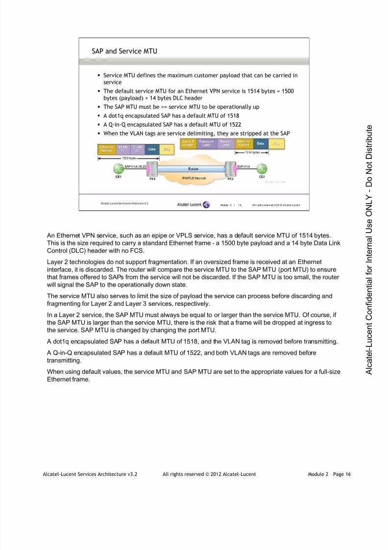
7/21/2019 Services Architecture v3.2 Student Guide Download
http://slidepdf.com/reader/full/services-architecture-v32-student-guide-download 117/429
Alcatel-Lucent Services Architecture v3.2 All rights reserved © 2012 Alcatel-Lucent Module 2 – Page 16
Module 2 | 16 A ll r ights re se rved ©2012 A lcatel -LucentAlcatel-Lucent Services Architecture v3.2
SAP and Service MTU
Service MTU defines the maximum customer payload that can be carried in
service
The default service MTU for an Ethernet VPN service is 1514 bytes = 1500
bytes (payload) + 14 bytes DLC header
The SAP MTU must be >= service MTU to be operationally up
A dot1q encapsulated SAP has a default MTU of 1518
A Q-in-Q encapsulated SAP has a default MTU of 1522
When the VLAN tags are service delimiting, they are stripped at the SAP
An Ethernet VPN service, such as an epipe or VPLS service, has a default service MTU of 1514 bytes.
This is the size required to carry a standard Ethernet frame - a 1500 byte payload and a 14 byte Data Link
Control (DLC) header with no FCS.
Layer 2 technologies do not support fragmentation. If an oversized frame is received at an Ethernet
interface, it is discarded. The router will compare the service MTU to the SAP MTU (port MTU) to ensure
that frames offered to SAPs from the service will not be discarded. If the SAP MTU is too small, the router
will signal the SAP to the operationally down state.
The service MTU also serves to limit the size of payload the service can process before discarding and
fragmenting for Layer 2 and Layer 3 services, respectively.
In a Layer 2 service, the SAP MTU must always be equal to or larger than the service MTU. Of course, if
the SAP MTU is larger than the service MTU, there is the risk that a frame will be dropped at ingress to
the service. SAP MTU is changed by changing the port MTU.
A dot1q encapsulated SAP has a default MTU of 1518, and the VLAN tag is removed before transmitting.
A Q-in-Q encapsulated SAP has a default MTU of 1522, and both VLAN tags are removed before
transmitting.
When using default values, the service MTU and SAP MTU are set to the appropriate values for a full-size
Ethernet frame.

7/21/2019 Services Architecture v3.2 Student Guide Download
http://slidepdf.com/reader/full/services-architecture-v32-student-guide-download 118/429
Alcatel-Lucent Services Architecture v3.2 All rights reserved © 2012 Alcatel-Lucent Module 2 – Page 17
Module 2 | 17 A ll r ights re se rved ©2012 A lcatel -LucentAlcatel-Lucent Services Architecture v3.2
SAP and Service MTU (continued)
When the VLAN tags are not service delimiting, they are not stripped
at the SAP (for example: a default dot1Q SAP)
SAP MTU is changed by changing the port MTU
MTU problems arise when we have a configuration different from the regular default configuration. For
example, in a default dot1Q SAP, VLAN tags are not stripped at the SAP since they are not service
delimiting. The diagram shows a default dot1Q SAP for an epipe service.
The default SAP will accept a full-size frame of 1518 bytes (1500 byte payload), but since the VLAN tag is
not stripped from the customer frame, the service payload is 1518 bytes. A frame of this size exceeds the
service MTU of 1514 and the frame is dropped. Therefore, to carry a full-size Ethernet frame for the
default dot1Q SAP, we need a service MTU of 1518. to configure the service for this larger MTU, the
command PE1 # config>service>epipe# service-mtu 1518 is used. When increasing the service MTU
we must also consider the SDP path MTU which is discussed in the following slides.
A null encapsulated SAP behaves in the same manner as a dot1Q default SAP and has the same issue if
it receives VLAN tagged frames.
To configure a service MTU the command is
conf i gur e servi ce <servi ce t ype> <servi ce i d> servi ce- mt u <octet s>
<oct et s> : [ 1. . 9194]

7/21/2019 Services Architecture v3.2 Student Guide Download
http://slidepdf.com/reader/full/services-architecture-v32-student-guide-download 119/429
Alcatel-Lucent Services Architecture v3.2 All rights reserved © 2012 Alcatel-Lucent Module 2 – Page 18
Module 2 | 18 A ll r ights re se rved ©2012 A lcatel -LucentAlcatel-Lucent Services Architecture v3.2
VC-MTU
Layer 2 services: service MTU is configured
VC-MTU = configured service MTU — 14 (DLC header)
Layer 3 services: service MTU is not configured VC-MTU of Layer 3 service interface can be configured by configuring the IP-MTU
parameter under the service
VC-MTU = configured SDP path MTU — 14 (DLC header)
If the SDP path MTU is not configured, the SDP path MTU and the VC-MTU are
derived from the network port MTU
• SDP path MTU = network port MTU — 4 (transport label) — 4 (VC-label) —
port encapsulation (14 in case of null encapsulation, 18 in case of
Dot1Q...)
• VC-MTU = network port MTU — 4 (transport label) — 4 (VC-label) — 14
(port encapsulation in case of null ..) — 14 Ethernet overhead
The VC-MTU is derived from the configured service MTU (VC-MTU = configured service MTU — 14
(Ethernet overhead, FCS not counted)). By default, epipe and VPLS services are configured with a service
MTU of 1514. By default, the signaled VC-MTU is 1500.
Layer 3 services have no service MTU configured. By default, there is also no SDP path MTU configured.
Whereas in Epipe and VPLS services the signaled VC-MTU = configured ‘service-mtu’ – 14 (ethernet), in
the case of a Layer 3 service, the signaled VC-MTU = configured ‘IP-MTU.’
VC-MTU of a Layer 3 interface can be configured by configuring the IP-MTU parameter under the Layer 3
service.
PE>conf i g>ser vi ce>vpr n# i nter f ace t oCust omerVPRN ip-mtu
- i p- mtu <octets>
- no i p- mtu
<octets> : [ 512. . 9000]
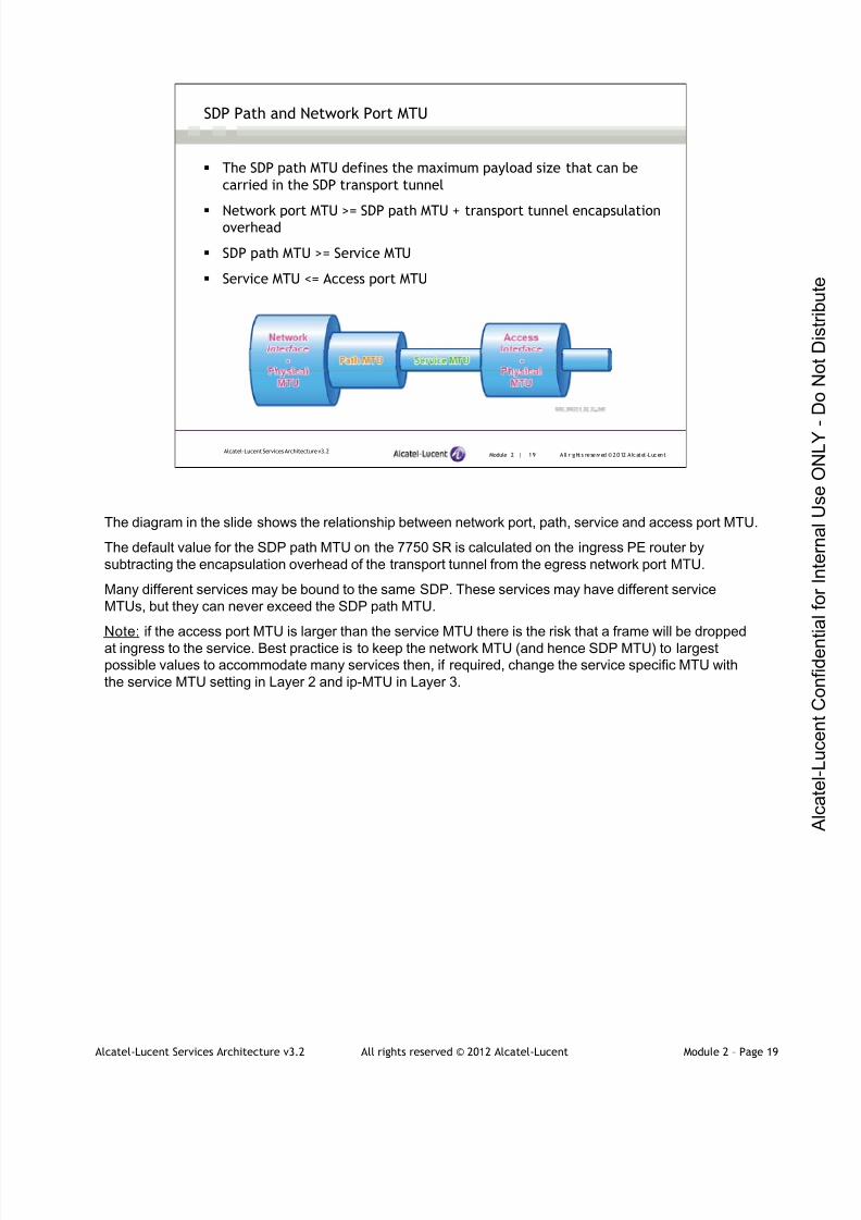
7/21/2019 Services Architecture v3.2 Student Guide Download
http://slidepdf.com/reader/full/services-architecture-v32-student-guide-download 120/429
Alcatel-Lucent Services Architecture v3.2 All rights reserved © 2012 Alcatel-Lucent Module 2 – Page 19
Module 2 | 19 A ll r ights re se rved ©2012 A lcatel -LucentAlcatel-Lucent Services Architecture v3.2
SDP Path and Network Port MTU
The SDP path MTU defines the maximum payload size that can be
carried in the SDP transport tunnel
Network port MTU >= SDP path MTU + transport tunnel encapsulationoverhead
SDP path MTU >= Service MTU
Service MTU <= Access port MTU
The diagram in the slide shows the relationship between network port, path, service and access port MTU.
The default value for the SDP path MTU on the 7750 SR is calculated on the ingress PE router by
subtracting the encapsulation overhead of the transport tunnel from the egress network port MTU.
Many different services may be bound to the same SDP. These services may have different service
MTUs, but they can never exceed the SDP path MTU.
Note: if the access port MTU is larger than the service MTU there is the risk that a frame will be dropped
at ingress to the service. Best practice is to keep the network MTU (and hence SDP MTU) to largest
possible values to accommodate many services then, if required, change the service specific MTU with
the service MTU setting in Layer 2 and ip-MTU in Layer 3.
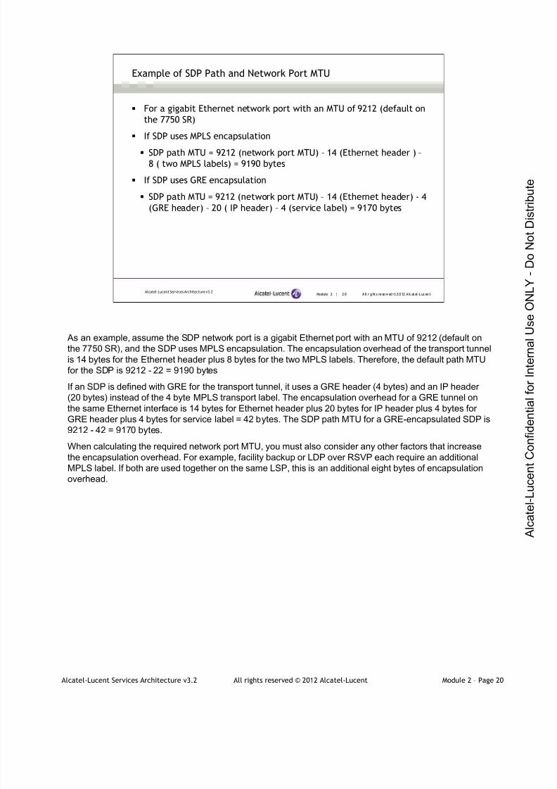
7/21/2019 Services Architecture v3.2 Student Guide Download
http://slidepdf.com/reader/full/services-architecture-v32-student-guide-download 121/429
Alcatel-Lucent Services Architecture v3.2 All rights reserved © 2012 Alcatel-Lucent Module 2 – Page 20
Module 2 | 20 A ll r ights re se rved ©2012 A lcatel -LucentAlcatel-Lucent Services Architecture v3.2
Example of SDP Path and Network Port MTU
For a gigabit Ethernet network port with an MTU of 9212 (default on
the 7750 SR)
If SDP uses MPLS encapsulation
SDP path MTU = 9212 (network port MTU) – 14 (Ethernet header ) –
8 ( two MPLS labels) = 9190 bytes
If SDP uses GRE encapsulation
SDP path MTU = 9212 (network port MTU) – 14 (Ethernet header) - 4
(GRE header) – 20 ( IP header) – 4 (service label) = 9170 bytes
As an example, assume the SDP network port is a gigabit Ethernet port with an MTU of 9212 (default on
the 7750 SR), and the SDP uses MPLS encapsulation. The encapsulation overhead of the transport tunnel
is 14 bytes for the Ethernet header plus 8 bytes for the two MPLS labels. Therefore, the default path MTU
for the SDP is 9212 - 22 = 9190 bytes
If an SDP is defined with GRE for the transport tunnel, it uses a GRE header (4 bytes) and an IP header
(20 bytes) instead of the 4 byte MPLS transport label. The encapsulation overhead for a GRE tunnel on
the same Ethernet interface is 14 bytes for Ethernet header plus 20 bytes for IP header plus 4 bytes for
GRE header plus 4 bytes for service label = 42 bytes. The SDP path MTU for a GRE-encapsulated SDP is
9212 - 42 = 9170 bytes.
When calculating the required network port MTU, you must also consider any other factors that increase
the encapsulation overhead. For example, facility backup or LDP over RSVP each require an additional
MPLS label. If both are used together on the same LSP, this is an additional eight bytes of encapsulation
overhead.

7/21/2019 Services Architecture v3.2 Student Guide Download
http://slidepdf.com/reader/full/services-architecture-v32-student-guide-download 122/429
Alcatel-Lucent Services Architecture v3.2 All rights reserved © 2012 Alcatel-Lucent Module 2 – Page 21
Module 2 | 21 A ll r ights re se rved ©2012 A lcatel -LucentAlcatel-Lucent Services Architecture v3.2
Physical MTU Default Values
The default MTU value depends on the port or sub-port type, the
mode and the encapsulation, which are listed in the table below:
Port Type Mode Encap Type Default (Bytes)
Ethernet access null 1514
Ethernet access Dot1Q 1518
Ethernet access Q-in-Q 1522
Fast Ethernet network - 1514
Gigabit Ethernet network - 9212
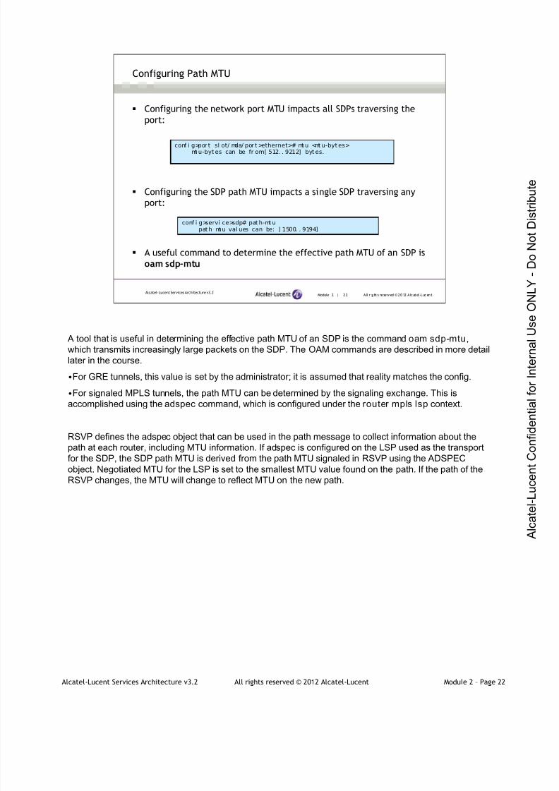
7/21/2019 Services Architecture v3.2 Student Guide Download
http://slidepdf.com/reader/full/services-architecture-v32-student-guide-download 123/429
Alcatel-Lucent Services Architecture v3.2 All rights reserved © 2012 Alcatel-Lucent Module 2 – Page 22
Module 2 | 22 A ll r ights re se rved ©2012 A lcatel -LucentAlcatel-Lucent Services Architecture v3.2
Configuring Path MTU
Configuring the network port MTU impacts all SDPs traversing the
port:
Configuring the SDP path MTU impacts a single SDP traversing any
port:
A useful command to determine the effective path MTU of an SDP is
oam sdp-mtu
conf i g>por t sl ot/ mda/ por t >ethernet># mt u <mt u-byt es>mt u-byt es can be fr om[ 512. . 9212] byt es.
conf i g>servi ce>sdp# pat h-mt upat h mt u val ues can be: [ 1500. . 9194]
A tool that is useful in determining the effective path MTU of an SDP is the command oam sdp-mtu,
which transmits increasingly large packets on the SDP. The OAM commands are described in more detail
later in the course.
•For GRE tunnels, this value is set by the administrator; it is assumed that reality matches the config.
•For signaled MPLS tunnels, the path MTU can be determined by the signaling exchange. This is
accomplished using the adspec command, which is configured under the router mpls lsp context.
RSVP defines the adspec object that can be used in the path message to collect information about the
path at each router, including MTU information. If adspec is configured on the LSP used as the transport
for the SDP, the SDP path MTU is derived from the path MTU signaled in RSVP using the ADSPEC
object. Negotiated MTU for the LSP is set to the smallest MTU value found on the path. If the path of the
RSVP changes, the MTU will change to reflect MTU on the new path.

7/21/2019 Services Architecture v3.2 Student Guide Download
http://slidepdf.com/reader/full/services-architecture-v32-student-guide-download 124/429
Alcatel-Lucent Services Architecture v3.2 All rights reserved © 2012 Alcatel-Lucent Module 2 – Page 23
Module 2 | 23 A ll r ights re se rved ©2012 A lcatel -LucentAlcatel-Lucent Services Architecture v3.2
Epipe MTU Case Study
The core network is configured with OSPF as the routing protocol
The customer sites connect to the PE nodes using dot1Q Ethernet
encapsulation
The SDP between the PE routers uses RSVP-signaled LSPs for transport
Epipe service is configured between PE1 and PE2

7/21/2019 Services Architecture v3.2 Student Guide Download
http://slidepdf.com/reader/full/services-architecture-v32-student-guide-download 125/429
Alcatel-Lucent Services Architecture v3.2 All rights reserved © 2012 Alcatel-Lucent Module 2 – Page 24
Module 2 | 24 A ll r ights re se rved ©2012 A lcatel -LucentAlcatel-Lucent Services Architecture v3.2
Epipe MTU Case Study – Port Configuration
*A: CE1# conf i gure port 1/1/3*A:CE1>conf i g>port# i nfo- - - - - - - - - - - - - - - - - - - - - - - - - - - - - - -
ether netencap- t ype dot1q
exi tno shut down
- - - - - - - - - - - - - - - - - - - - - - - - - - - - - - -
*A:PE-1# show port===============================================================================Port s on Sl ot 1===============================================================================Port Admin Link Port Cfg Oper LAG/ Port Port Port SFP/XFP/I d State State MTU MTU Bndl Mode Encp Type MDI MDX- - - - - - - - - - - - - - - - - - - - - - - -- - - - - - - - - - - - - - - - - - - - - - - -- - - - - - - - - - - - - - - - - - - - - - - - -- - - - - -1/1/1 Down No Down 9212 9212 - netw nul l gige
1/1/2 Down No Down 9212 9212 - netw nul l gige1/1/3 Up Yes Up 9212 9212 - netw null gige
1/1/4 Up Yes Up 1518 1518 - accs dotq gige
…
*A:P1# show port===============================================================================Port s on Sl ot 1===============================================================================Port Admin Link Port Cfg Oper LAG/ Port Port Port SFP/XFP/I d State State MTU MTU Bndl Mode Encp Type MDI MDX- - - - - - - - - - - - - - - - - - - - - - - -- - - - - - - - - - - - - - - - - - - - - - - -- - - - - - - - - - - - - - - - - - - - - - - - -- - - - - -1/1/1 Down No Down 9212 9212 - netw nul l gige1/1/2 Down No Down 9212 9212 - netw nul l gige1/1/3 Up Yes Up 9212 9212 - netw null gige
1/1/4 Up Yes Up 9212 9212 - netw null gige
…
*A: PE-1# confi gure port 1/1/4
*A:PE-1>conf i g>port # i nfo- - - - - - - - - - - - - - - - - - - - - - - - - - - - - - -
ether netmode ac cess
encap- t ype dot1qexi tno shut down
- - - - - - - - - - - - - - - - - - - - - - - - - - - - - - -
The configuration of the customer-facing port on PE1 (port 1/1/4) is shown, similar configuration exists on
PE2 for port 1/1/4.
Note: the network port MTU value is 9212 for the gig Ethernet port.
Since the encapsulation type used is dot1q, the MTU value for the SAP is 1514 + 4 (VLAN tag) = 1518
The configuration of the customer port facing the PE router on CE1 (port 1/1/3) is shown, similar
configuration exists on CE2 for port 1/1/3.
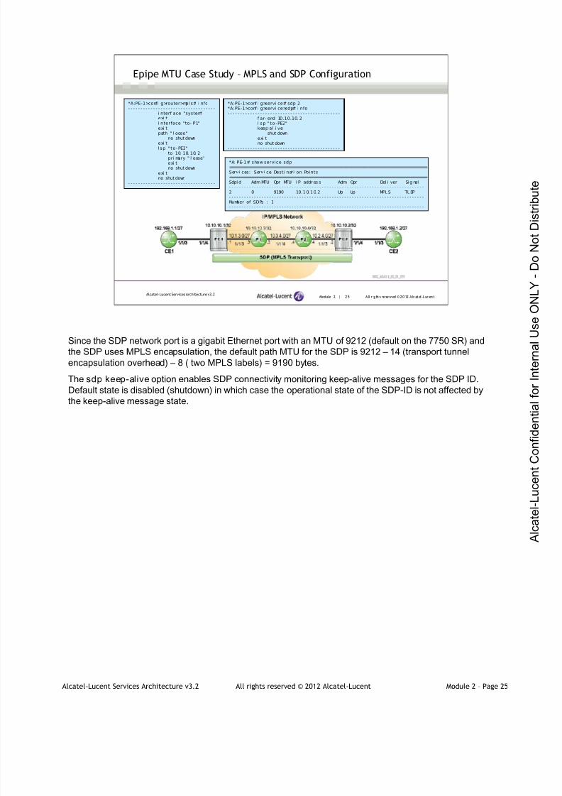
7/21/2019 Services Architecture v3.2 Student Guide Download
http://slidepdf.com/reader/full/services-architecture-v32-student-guide-download 126/429
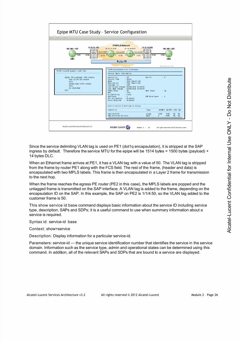
7/21/2019 Services Architecture v3.2 Student Guide Download
http://slidepdf.com/reader/full/services-architecture-v32-student-guide-download 127/429
Alcatel-Lucent Services Architecture v3.2 All rights reserved © 2012 Alcatel-Lucent Module 2 – Page 26
Module 2 | 26 A ll r ights re se rved ©2012 A lcatel -LucentAlcatel-Lucent Services Architecture v3.2
Epipe MTU Case Study – Service Configuration
*A:PE-1>conf i g>servi ce# i nfo- - - - - - - - - - - - - - - - - - - - - - - - - - - - - - - - - - - - - - - - -
…epipe 50 customer 100 creat e
sap 1/ 1/4: 50 createexi tspoke-sdp 2:50 createexi tno shut down
exi t- - - - - - - - - - - - - - - - - - - - - - - - - - - - - - - - - - - - - - - - -
*A:PE-1# showser vi ce i d 50 base===============================================================================Service Basi c Infor mati on===============================================================================Service I d : 50 Vpn I d : 0Service Type : Epi peName : (Not Specif i ed)Descripti on : (Not Specif i ed)Cust omer I d : 100Last St atus Change: 02/09/ 2012 15: 09:34Last Mgmt Change : 02/09/ 2012 15: 09:34Admi n State : Up Oper State : Up
MTU : 1514
Vc Swi tchi ng : FalseSAP Count : 1 SDP Bi nd Count : 1Per Svc Hashing : Di sabledForce QTag Fwd : Di sabled
- - - - - - - - - - - - - - - - - - - - - - -- - - - - - - - - - - - - - - - - - - - - - - - -- - - - - - - - - - - - - - - - - - - - - - - -- - - - - - -Servi ce Access & Desti nati on Poi nts- - - - - - - - - - - - - - - - - - - - - - -- - - - - - - - - - - - - - - - - - - - - - - - -- - - - - - - - - - - - - - - - - - - - - - - -- - - - - - -I denti fi er Type AdmMTU OprMTU Adm Opr- - - - - - - - - - - - - - - - - - - - - - -- - - - - - - - - - - - - - - - - - - - - - - - -- - - - - - - - - - - - - - - - - - - - - - - -- - - - - - -sap:1/1/4:50 q-tag 1518 1518 Up Up
sdp:2:50 S(10.10.10.2) Spok 0 9190 Up Up
===============================================================================
Since the service delimiting VLAN tag is used on PE1 (dot1q encapsulation), it is stripped at the SAP
ingress by default. Therefore the service MTU for the epipe will be 1514 bytes = 1500 bytes (payload) +
14 bytes DLC.
When an Ethernet frame arrives at PE1, it has a VLAN tag with a value of 50. The VLAN tag is stripped
from the frame by router PE1 along with the FCS field. The rest of the frame, (header and data) is
encapsulated with two MPLS labels. This frame is then encapsulated in a Layer 2 frame for transmission
to the next hop.
When the frame reaches the egress PE router (PE2 in this case), the MPLS labels are popped and the
untagged frame is transmitted on the SAP interface. A VLAN tag is added to the frame, depending on the
encapsulation ID on the SAP. In this example, the SAP on PE2 is 1/1/4:50, so the VLAN tag added to the
customer frame is 50.
This show service id base command displays basic information about the service ID including service
type, description, SAPs and SDPs; it is a useful command to use when summary information about a
service is required.
Syntax id: service-id base
Context: show>service
Description: Display information for a particular service-id.
Parameters: service-id — the unique service identification number that identifies the service in the service
domain. Information such as the service type, admin and operational states can be determined using this
command. In addition, all of the relevant SAPs and SDPs that are bound to a service are displayed.
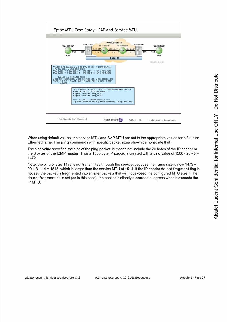
7/21/2019 Services Architecture v3.2 Student Guide Download
http://slidepdf.com/reader/full/services-architecture-v32-student-guide-download 128/429
Alcatel-Lucent Services Architecture v3.2 All rights reserved © 2012 Alcatel-Lucent Module 2 – Page 27
Module 2 | 27 A ll r ights re se rved ©2012 A lcatel -LucentAlcatel-Lucent Services Architecture v3.2
Epipe MTU Case Study – SAP and Service MTU
*A: CE1# pi ng 192.168.1. 2 si ze 1472 do-not- f ragment count 2PI NG 192. 168.1. 2 1472 data bytes1480 bytes f rom 192. 168.1. 2: i cmp_seq=1 t t l =64 ti me=5.01ms.1480 bytes f rom 192. 168.1. 2: i cmp_seq=2 t t l =64 ti me=4.80ms.
- - - - 192.168.1 .2 PINGS tat i s t ic s - - - -2 packets t ransmi t ted, 2 packets recei ved, 0.00%packet l ossround-t ri p mi n = 4.80ms, avg = 4.90ms, max = 5.01ms, stddev
= 0. 105ms
*A: CE1# pi ng 192.168.1. 2 si ze 1473 do-not- f ragment count 2PI NG 192. 168.1. 2 1473 data byt esRequest t i med out. i cmp_seq=1.Request t i med out. i cmp_seq=2.
- - - - 192.168.1 .2 PINGS tat i s t ic s - - - -2 packets t ransmi tt ed, 0 packet s r ecei ved, 100%packet l oss
When using default values, the service MTU and SAP MTU are set to the appropriate values for a full-size
Ethernet frame. The ping commands with specific packet sizes shown demonstrate that.
The size value specifies the size of the ping packet, but does not include the 20 bytes of the IP header or
the 8 bytes of the ICMP header. Thus a 1500 byte IP packet is created with a ping value of 1500 - 20 - 8 =
1472.
Note: the ping of size 1473 is not transmitted through the service, because the frame size is now 1473 +
20 + 8 + 14 = 1515, which is larger than the service MTU of 1514. If the IP header do not fragment flag isnot set, the packet is fragmented into smaller packets that will not exceed the configured MTU size. If the
do not fragment bit is set (as in this case), the packet is silently discarded at egress when it exceeds the
IP MTU.

7/21/2019 Services Architecture v3.2 Student Guide Download
http://slidepdf.com/reader/full/services-architecture-v32-student-guide-download 129/429
Alcatel-Lucent Services Architecture v3.2 All rights reserved © 2012 Alcatel-Lucent Module 2 – Page 28
Module 2 | 28 A ll r ights re se rved ©2012 A lcatel -LucentAlcatel-Lucent Services Architecture v3.2
Epipe MTU Case Study – Changing the Service MTU
*A:PE-1>conf i g>servi ce>epi pe# i nfo- - - - - - - - - - - - - - - - - - - - - - - - - - - - - - - - - - - - - - - - - -
servi ce-mtu 1518sap 1/ 1/4: 50 createexi tspoke-sdp 2:50 createexi tno shut down
- - - - - - - - - - - - - - - - - - - - - - - - - - - - - - - - - - - - - - - - - -
*A:PE-1# showser vi ce i d 50 base===============================================================================Service Basi c Infor mati on===============================================================================Service I d : 50 Vpn I d : 0Service Type : Epi peName : (Not Specif i ed)Descripti on : (Not Specif i ed)Cust omer I d : 100Last St atus Change: 02/09/ 2012 15: 55:19Last Mgmt Change : 02/09/ 2012 15: 55:19Admi n Stat e : Up Oper Stat e : Down
MTU : 1518
Vc Swi tchi ng : FalseSAP Count : 1 SDP Bi nd Count : 1Per Svc Hashing : Di sabledForce QTag Fwd : Di sabled
- - - - - - - - - - - - - - - - - - - - - - -- - - - - - - - - - - - - - - - - - - - - - - - -- - - - - - - - - - - - - - - - - - - - - - - -- - - - - - -Servi ce Access & Desti nati on Poi nts- - - - - - - - - - - - - - - - - - - - - - -- - - - - - - - - - - - - - - - - - - - - - - - -- - - - - - - - - - - - - - - - - - - - - - - -- - - - - - -I denti fi er Type AdmMTU OprMTU Adm Opr- - - - - - - - - - - - - - - - - - - - - - -- - - - - - - - - - - - - - - - - - - - - - - - -- - - - - - - - - - - - - - - - - - - - - - - -- - - - - - -sap:1/1/4:50 q-tag 1518 1518 Up Down
sdp:2:50 S(10.10.10.2) Spok 0 9190 Up Up
===============================================================================
*A:PE-2>conf i g>servi ce>epi pe# i nfo- - - - - - - - - - - - - - - - - - - - - - - - - - - - - - - - - - - - - - - - - -
servi ce-mtu 1518sap 1/ 1/4: 50 createexi tspoke-sdp 1:50 createexi tno shut down
- - - - - - - - - - - - - - - - - - - - - - - - - - - - - - - - - - - - - - - - - -
When the service MTU is changed on both PE routers, the entire service goes down because SAP-MTU
can not support the new service.
The SAP-MTU must be changed so that it can support the service MTU.
Port-MTU >= service-MTU + MAX egress encapsulation
In this case, since the SAP is dot1Q encapsulated, it must be changed to 1522 (service MTU + 4 bytesDot1Q encap).
Note: if the MTU is increased on PE1 only, then the SDP binding will also be down. The service MTU is
used in the T-LDP signaling of the pseudowire and must match at both ends of the service. We increased
the MTU on both PE1 and PE2 and the path MTU is up.
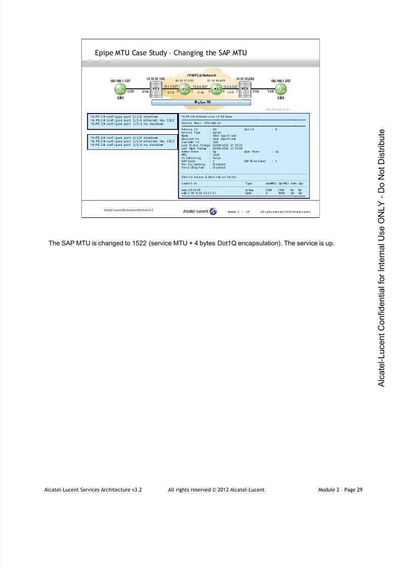
7/21/2019 Services Architecture v3.2 Student Guide Download
http://slidepdf.com/reader/full/services-architecture-v32-student-guide-download 130/429
Alcatel-Lucent Services Architecture v3.2 All rights reserved © 2012 Alcatel-Lucent Module 2 – Page 29
Module 2 | 29 A ll r ights re se rved ©2012 A lcatel -LucentAlcatel-Lucent Services Architecture v3.2
Epipe MTU Case Study – Changing the SAP MTU
*A:PE-1# conf i gure port 1/ 1/4 shutdown*A: PE-1# confi gure port 1/1/4 ethernet mtu 1522*A:PE-1# conf i gure port 1/1/ 4 no shutdown
*A:PE-1# showser vi ce i d 50 base===============================================================================Service Basi c Infor mati on===============================================================================Service I d : 50 Vpn I d : 0Service Type : Epi peName : (Not Specif i ed)Descripti on : (Not Specif i ed)Cust omer I d : 100Last St atus Change: 02/09/ 2012 17: 19:33Last Mgmt Change : 02/09/ 2012 17: 15:58Admi n State : Up Oper State : UpMTU : 1518Vc Swi tchi ng : FalseSAP Count : 1 SDP Bi nd Count : 1Per Svc Hashing : Di sabledForce QTag Fwd : Di sabled
- - - - - - - - - - - - - - - - - - - - - - -- - - - - - - - - - - - - - - - - - - - - - - - -- - - - - - - - - - - - - - - - - - - - - - - -- - - - - - -Servi ce Access & Desti nati on Poi nts- - - - - - - - - - - - - - - - - - - - - - -- - - - - - - - - - - - - - - - - - - - - - - - -- - - - - - - - - - - - - - - - - - - - - - - -- - - - - - -I denti fi er Type AdmMTU OprMTU Adm Opr- - - - - - - - - - - - - - - - - - - - - - -- - - - - - - - - - - - - - - - - - - - - - - - -- - - - - - - - - - - - - - - - - - - - - - - -- - - - - - -sap:1/1/4:50 q-tag 1522 1522 Up Up
sdp:2 :50 S( 10. 1 0. 1 0. 2 ) Spok 0 9190 Up Up===============================================================================
*A:PE-2# conf i gure port 1/ 1/4 shutdown*A: PE-2# confi gure port 1/1/4 ethernet mtu 1522*A:PE-2# conf i gure port 1/1/ 4 no shutdown
The SAP MTU is changed to 1522 (service MTU + 4 bytes Dot1Q encapsulation). The service is up.
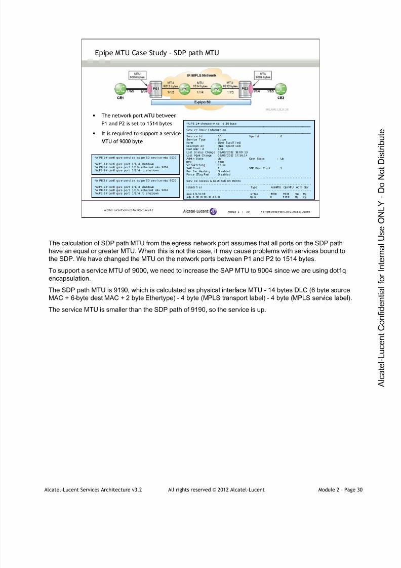
7/21/2019 Services Architecture v3.2 Student Guide Download
http://slidepdf.com/reader/full/services-architecture-v32-student-guide-download 131/429
Alcatel-Lucent Services Architecture v3.2 All rights reserved © 2012 Alcatel-Lucent Module 2 – Page 30
Module 2 | 30 A ll r ights re se rved ©2012 A lcatel -LucentAlcatel-Lucent Services Architecture v3.2
Epipe MTU Case Study – SDP path MTU
*A: PE-1# confi gure servi ce epi pe 50 servi ce-mtu 9000
*A:PE-1# confi gure port 1/1/ 4 shutdown*A: PE-1# confi gure port 1/1/4 ethernet mtu 9004*A:PE-1# confi gure port 1/1/ 4 no shutdown
*A:PE-1# showser vi ce i d 50 base===============================================================================Servi ce Basi c I nformati on===============================================================================Servi ce I d : 50 Vpn I d : 0Service Type : Epi peName : (Not Specif i ed)Descripti on : (Not Specif i ed)Cust omer I d : 100Last St atus Change: 02/09/ 2012 18:00: 13Last Mgmt Change : 02/09/ 2012 17: 56:14Admi n State : Up Oper State : Up
MTU : 9000
Vc Swi tching : Fal seSAP Count : 1 SDP Bind Count : 1Per Svc Hashing : Di sabledForce QTag Fwd : Di sabled- - - - - - - - - - - - - - - - - - - - - - - - -- - - - - - - - - - - - - - - - - - - - - - - -- - - - - - - - - - - - - - - - - - - - - - - - -- - - - -Servi ce Access & Desti nati on Points- - - - - - - - - - - - - - - - - - - - - - - - -- - - - - - - - - - - - - - - - - - - - - - - -- - - - - - - - - - - - - - - - - - - - - - - - -- - - - -I denti fi er Type AdmMTU OprMTU Adm Opr- - - - - - - - - - - - - - - - - - - - - - - - -- - - - - - - - - - - - - - - - - - - - - - - -- - - - - - - - - - - - - - - - - - - - - - - - -- - - - -sap:1/1/4:50 q-tag 9004 9004 Up Up
sdp:2:50 S(10.10.10.2) Spok 0 9190 Up Up
The network port MTU between
P1 and P2 is set to 1514 bytes
It is required to support a service
MTU of 9000 byte
*A: PE-2# confi gure servi ce epi pe 50 servi ce-mtu 9000
*A:PE-2# confi gure port 1/1/ 4 shutdown*A: PE-2# confi gure port 1/1/4 ethernet mtu 9004*A:PE-2# confi gure port 1/1/ 4 no shutdown
The calculation of SDP path MTU from the egress network port assumes that all ports on the SDP path
have an equal or greater MTU. When this is not the case, it may cause problems with services bound to
the SDP. We have changed the MTU on the network ports between P1 and P2 to 1514 bytes.
To support a service MTU of 9000, we need to increase the SAP MTU to 9004 since we are using dot1q
encapsulation.
The SDP path MTU is 9190, which is calculated as physical interface MTU - 14 bytes DLC (6 byte source
MAC + 6-byte dest MAC + 2 byte Ethertype) - 4 byte (MPLS transport label) - 4 byte (MPLS service label).
The service MTU is smaller than the SDP path of 9190, so the service is up.

7/21/2019 Services Architecture v3.2 Student Guide Download
http://slidepdf.com/reader/full/services-architecture-v32-student-guide-download 132/429
Alcatel-Lucent Services Architecture v3.2 All rights reserved © 2012 Alcatel-Lucent Module 2 – Page 31
Module 2 | 31 A ll r ights re se rved ©2012 A lcatel -LucentAlcatel-Lucent Services Architecture v3.2
Epipe MTU Case Study – SDP path MTU (continued)
*A:CE1# ping 192.168. 1.2 si ze 1450 do-not- f ragment count 1PI NG 192.168. 1.2 1450 data bytes1458 bytes from 192.168.1.2: icmp_seq=1 ttl=64 time=5.08ms.
- - - - 192.168.1 .2 P ING Stat i st i cs - - - -1 packet tr ansmi tt ed, 1 packet received, 0.00%packet l ossround- tr i p mi n = 5.08ms, avg = 5.08ms, max =5. 08ms, st ddev = 0.000ms
*A:CE1# ping 192.168.1.2 si ze 1451 do-not- f ragment count 1PI NG 192. 168. 1. 2 1451 data byt esRequest timed out. icmp_seq=1.
- - - - 192 .168.1 .2 P ING Stat i st i cs - - - -1 packet tr ansmi tt ed, 0 packets received, 100%packet l oss
The epipe service does not support anywhere near the size frame expected
with a service MTU of 9000 bytes
Although we can ping across the epipe, we find that it does not support anywhere near the size frame
expected with a service MTU of 9000 bytes. The maximum size ping is found to be 1450 bytes. The size
of the frame transmitted on the network port for this ping can be calculated as 1450 plus 28 byte IP/ICMP
header plus 14 byte payload Ethernet header plus 22 bytes transport encapsulation overhead = 1514
bytes. This is exactly as expected since the link MTU between PE1 and PE2 is 1514.
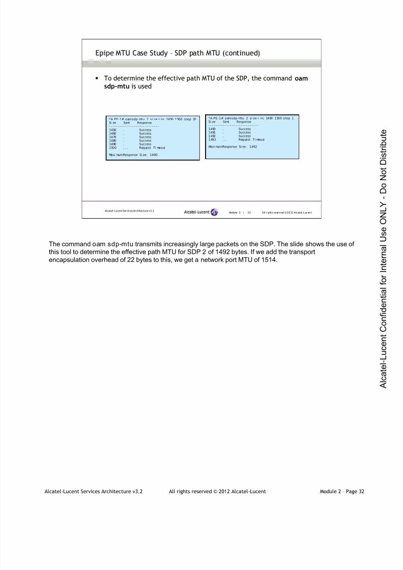
7/21/2019 Services Architecture v3.2 Student Guide Download
http://slidepdf.com/reader/full/services-architecture-v32-student-guide-download 133/429
Alcatel-Lucent Services Architecture v3.2 All rights reserved © 2012 Alcatel-Lucent Module 2 – Page 32
Module 2 | 32 A ll r ights re se rved ©2012 A lcatel -LucentAlcatel-Lucent Services Architecture v3.2
Epipe MTU Case Study – SDP path MTU (continued)
*A:PE-1# oamsdp-mtu 2 si ze-i nc 1450 1500 step 10Si ze Sent Response- - - - - - - - - - - - - - - - - - - - - - - - - - - -1450 . Success1460 . Success1470 . Success1480 . Success1490 . Success1500 . . . Request Ti meout
Maxi mumResponse Si ze: 1490
To determine the effective path MTU of the SDP, the command oamsdp-mtu is used
*A:PE-1# oamsdp-mtu 2 si ze-i nc 1490 1500 step 1Si ze Sent Response- - - - - - - - - - - - - - - - - - - - - - - - - - - -1490 . Success1491 . Success1492 . Success1493 . . . Request Ti meout
Maxi mumResponse Si ze: 1492
The command oam sdp-mtu transmits increasingly large packets on the SDP. The slide shows the use of
this tool to determine the effective path MTU for SDP 2 of 1492 bytes. If we add the transport
encapsulation overhead of 22 bytes to this, we get a network port MTU of 1514.

7/21/2019 Services Architecture v3.2 Student Guide Download
http://slidepdf.com/reader/full/services-architecture-v32-student-guide-download 134/429
Alcatel-Lucent Services Architecture v3.2 All rights reserved © 2012 Alcatel-Lucent Module 2 – Page 33
Module 2 | 33 A ll r ights re se rved ©2012 A lcatel -LucentAlcatel-Lucent Services Architecture v3.2
Epipe MTU Case Study – SDP path-MTU - Verify Path MTU Using RSVP ADSPEC
*A:PE-1>conf i g>router>mpls# l sp "t o-PE2"*A: PE-1>confi g>rout er>mpl s>l sp# adspec*A:PE-1>conf i g>router>mpls>lsp# i nfo- - - - - - - - - - - - - - - - - - - - - - - - - - - - - - - - - - - - - - - - - -
to 10. 10. 10. 2adspecpri mary "l oose"exi tno shut down
- - - - - - - - - - - - - - - - - - - - - - - - - - - - - - - - - - - - - - - - - - -
If ADSPEC is configured on the LSP used as the transport for the SDP, the SDP path-
MTU is derived from the path MTU signaled in RSVP using the ADSPEC object
Negotiated MTU for the LSP is set to the smallest MTU value found on the path
*A:PE-1# show router mpls l sp "t o-PE2" path detai l===============================================================================MPLS LSP to- PE2 Path (Detai l )===============================================================================Legend :
@- Detour Avai lable # - Detour In Useb - Bandwi dth Protected n - Node Protecteds - Soft Preempti on
===============================================================================LSP to-PE2 Path l oose- - - - - - - - - - - - - - - - - - - - - - -- - - - - - - - - - - - - - - - - - - - - - - -- - - - - - - - - - - - - - - - - - - - - - - - -- - - - - - -LSP Name : to- PE2 Path LSP I D : 38922From : 10. 10. 10. 1 To : 10. 10. 10. 2AdmStat e : Up Oper State : UpPath Name : l oose Path Type : Pri maryPath Admi n : Up Path Oper : UpOutI nterf ace: 1/1/ 3 Out Label : 131069….
Oper CT : 0Record Route: Record Record Label : RecordOper MTU : 1500 Neg MTU : 1500
Adapti ve : Enabl ed Oper Metr i c : 300I nclude Grps: Exclude Grps:
…
RSVP defines the ADSPEC object that can be used in the path message to collect information about the
path at each router, including MTU information.
Negotiated MTU for the LSP is set to the smallest MTU value found on the path. If the path of the RSVP
changes, the MTU will change to reflect MTU on the new path.
If ADSPEC is configured on the LSP used as the transport for the SDP, the SDP path MTU is derived from
the path MTU negotiated by RSVP-TE using the ADSPEC object. Notice that the LSP MTU is 1500 bytes.
The SDP path MTU is 8 bytes less to accommodate the two MPLS labels.
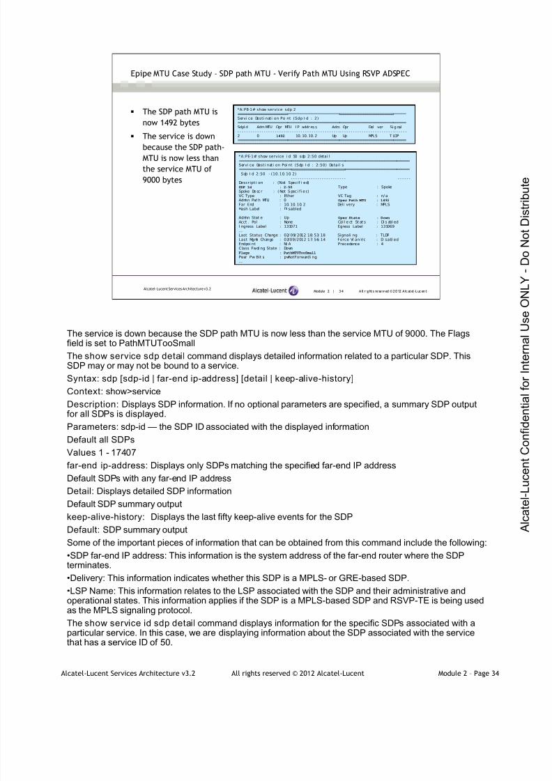
7/21/2019 Services Architecture v3.2 Student Guide Download
http://slidepdf.com/reader/full/services-architecture-v32-student-guide-download 135/429
Alcatel-Lucent Services Architecture v3.2 All rights reserved © 2012 Alcatel-Lucent Module 2 – Page 34
Module 2 | 34 A ll r ights re se rved ©2012 A lcatel -LucentAlcatel-Lucent Services Architecture v3.2
Epipe MTU Case Study – SDP path MTU - Verify Path MTU Using RSVP ADSPEC
*A:PE-1# show service i d 50 sdp 2:50 detai l===============================================================================Servi ce Desti nati on Poi nt (Sdp I d : 2:50) Detail s===============================================================================Sdp I d 2:50 - (10.10. 10. 2)
- - - - - - - - - - - - - - - - - - - - - - - -- - - - - - - - - - - - - - - - - - - - - - - - -- - - - - - - - - - - - - - - - - - - - - - - -- - - - - -Descripti on : (Not Specif i ed)SDP Id : 2:50 Type : SpokeSpoke De sc r : ( Not S pec i f i e d)VC Type : Ether VC Tag : n/ aAdmi n Path MTU : 0 Oper Path MTU : 1492
Far End : 10. 10. 10. 2 Deli very : MPLSHash Label : Di sabled
Admi n Stat e : Up Oper State : Down
Acct . Pol : None Col l e ct St at s : Di s abl edI ngress Label : 131071 Egress Label : 131069…Last Status Change : 02/ 09/ 2012 18: 53: 18 Signali ng : TLDPLast Mgmt Change : 02/09/2012 17: 56: 14 Force Vl an-Vc : Di sabl edEndpoi nt : N/ A Precedence : 4Class Fwdi ng State : DownFlags : PathMTUTooSmall
Peer Pw Bit s : pwNotForwardi ng…
The SDP path MTU is
now 1492 bytes
The service is downbecause the SDP path-
MTU is now less than
the service MTU of
9000 bytes
*A:PE-1# show service sdp 2==============================================================================Servi ce Desti nati on Poi nt (Sdp I d : 2)==============================================================================SdpI d Adm MTU Opr MTU I P addr es s Adm Opr Del i ver Si g nal- - - - - - - - - - - - - - - - - - - - - - -- - - - - - - - - - - - - - - - - - - - - - - -- - - - - - - - - - - - - - - - - - - - - - - - -- - - - - -
2 0 1492 10. 10. 10. 2 Up Up MPLS T LDP==============================================================================
The service is down because the SDP path MTU is now less than the service MTU of 9000. The Flagsfield is set to PathMTUTooSmall
The show service sdp detail command displays detailed information related to a particular SDP. ThisSDP may or may not be bound to a service.
Syntax: sdp [sdp-id | far-end ip-address] [detail | keep-alive-history]
Context: show>service
Description: Displays SDP information. If no optional parameters are specified, a summary SDP outputfor all SDPs is displayed.
Parameters: sdp-id — the SDP ID associated with the displayed information
Default all SDPs
Values 1 - 17407
far-end ip-address: Displays only SDPs matching the specified far-end IP address
Default SDPs with any far-end IP address
Detail: Displays detailed SDP information
Default SDP summary output
keep-alive-history: Displays the last fifty keep-alive events for the SDP
Default: SDP summary output
Some of the important pieces of information that can be obtained from this command include the following:•SDP far-end IP address: This information is the system address of the far-end router where the SDPterminates.
•Delivery: This information indicates whether this SDP is a MPLS- or GRE-based SDP.
•LSP Name: This information relates to the LSP associated with the SDP and their administrative andoperational states. This information applies if the SDP is a MPLS-based SDP and RSVP-TE is being usedas the MPLS signaling protocol.
The show service id sdp detail command displays information for the specific SDPs associated with aparticular service. In this case, we are displaying information about the SDP associated with the servicethat has a service ID of 50.
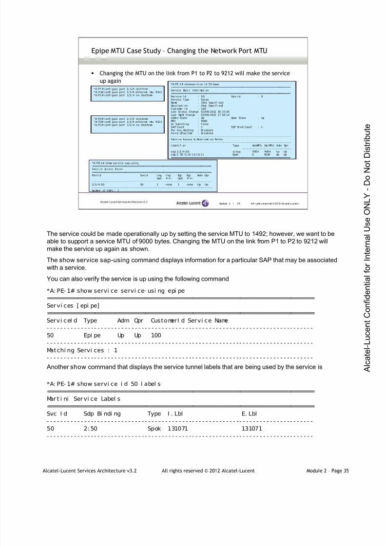
7/21/2019 Services Architecture v3.2 Student Guide Download
http://slidepdf.com/reader/full/services-architecture-v32-student-guide-download 136/429
Alcatel-Lucent Services Architecture v3.2 All rights reserved © 2012 Alcatel-Lucent Module 2 – Page 35
Module 2 | 35 A ll r ights re se rved ©2012 A lcatel -LucentAlcatel-Lucent Services Architecture v3.2
Epipe MTU Case Study – Changing the Network Port MTU
*A:P1# conf i gure port 1/ 1/4 shutdown*A: P1# confi gure port 1/1/4 ethernet mtu 9212
*A:P1# conf i gure port 1/1/ 4 no shutdown
Changing the MTU on the link from P1 to P2 to 9212 will make the service
up again*A:PE-1# showser vi ce i d 50 base===============================================================================Service Basi c Infor mati on===============================================================================Service I d : 50 Vpn I d : 0Service Type : Epi peName : (Not Specif i ed)Descripti on : (Not Specif i ed)Cust omer I d : 100Last St atus Change: 02/09/ 2012 19: 15:45Last Mgmt Change : 02/09/ 2012 17: 56:14Admi n State : Up Oper State : UpMTU : 9000Vc Swi tching : FalseSAP Count : 1 SDP Bi nd Count : 1Per Svc Hashing : Di sabledForce QTag Fwd : Di sabled- - - - - - - - - - - - - - - - - - - - - - -- - - - - - - - - - - - - - - - - - - - - - - -- - - - - - - - - - - - - - - - - - - - - - - - -- - - - - - -Servi ce Access & Desti nati on Points- - - - - - - - - - - - - - - - - - - - - - -- - - - - - - - - - - - - - - - - - - - - - - -- - - - - - - - - - - - - - - - - - - - - - - - -- - - - - - -I denti fi er Type AdmMTU OprMTU Adm Opr- - - - - - - - - - - - - - - - - - - - - - -- - - - - - - - - - - - - - - - - - - - - - - -- - - - - - - - - - - - - - - - - - - - - - - - -- - - - - - -sap: 1/1/4:50 q-tag 9004 9004 Up Upsdp:2 :50 S( 10. 1 0. 1 0. 2 ) Spok 0 9190 Up Up===============================================================================
*A:P2# conf i gure port 1/ 1/4 shutdown*A: P2# confi gure port 1/1/4 ethernet mtu 9212*A:P2# conf i gure port 1/1/ 4 no shutdown
*A: PE-1# show service sap-using===============================================================================Servi ce Access Poi nts===============================================================================Por t I d SvcI d I ng. I ng. Egr . Egr . Adm Opr
QoS Fl t r QoS Fl t r- - - - - - - - - - - - - - - - - - - - - -- - - - - - - - - - - - - - - - - - - - - - - - -- - - - - - - - - - - - - - - - - - - - - - - - -- - - - - - -1/ 1/ 4: 50 50 1 none 1 none Up Up- - - - - - - - - - - - - - - - - - - - - -- - - - - - - - - - - - - - - - - - - - - - - - -- - - - - - - - - - - - - - - - - - - - - - - - -- - - - - - -
Number of SAPs : 1
The service could be made operationally up by setting the service MTU to 1492; however, we want to be
able to support a service MTU of 9000 bytes. Changing the MTU on the link from P1 to P2 to 9212 will
make the service up again as shown.
The show service sap-using command displays information for a particular SAP that may be associated
with a service.
You can also verify the service is up using the following command
*A: PE- 1# show servi ce servi ce- usi ng epi pe
===============================================================================
Ser vi ces [ epi pe]
===============================================================================
Servi ceI d Type Adm Opr CustomerI d Servi ce Name
- - - - - - - - - - - - - - - - - - - - - - - - - - - - - - - - - - - - - - - - - - - - - - - - - - - - - - - - - - - - - - - - - - - - - - - - - - - - - - -
50 Epi pe Up Up 100
- - - - - - - - - - - - - - - - - - - - - - - - - - - - - - - - - - - - - - - - - - - - - - - - - - - - - - - - - - - - - - - - - - - - - - - - - - - - - - -
Matchi ng Servi ces : 1
- - - - - - - - - - - - - - - - - - - - - - - - - - - - - - - - - - - - - - - - - - - - - - - - - - - - - - - - - - - - - - - - - - - - - - - - - - - - - - -
Another show command that displays the service tunnel labels that are being used by the service is
*A: PE- 1# show servi ce i d 50 l abel s===============================================================================
Mar t i ni Ser vi ce Label s
===============================================================================
Svc I d Sdp Bi ndi ng Type I . Lbl E. Lbl
- - - - - - - - - - - - - - - - - - - - - - - - - - - - - - - - - - - - - - - - - - - - - - - - - - - - - - - - - - - - - - - - - - - - - - - - - - - - - - -
50 2: 50 Spok 131071 131071
- - - - - - - - - - - - - - - - - - - - - - - - - - - - - - - - - - - - - - - - - - - - - - - - - - - - - - - - - - - - - - - - - - - - - - - - - - - - - - -
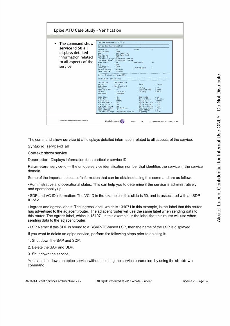
7/21/2019 Services Architecture v3.2 Student Guide Download
http://slidepdf.com/reader/full/services-architecture-v32-student-guide-download 137/429
Alcatel-Lucent Services Architecture v3.2 All rights reserved © 2012 Alcatel-Lucent Module 2 – Page 36
Module 2 | 36 A ll r ights re se rved ©2012 A lcatel -LucentAlcatel-Lucent Services Architecture v3.2
Epipe MTU Case Study – Verification
The command showservice id 50 alldisplays detailed
information relatedto all aspects of the
service
*A:PE-1# show service id 50 al l===============================================================================Service Detai l ed I nformati on===============================================================================Servi ce I d : 50 Vpn I d : 0Service Type : Epi peName : (Not Specif i ed)Descripti on : (Not Specif i ed)
Cust omer I d : 100Last Stat us Change: 02/ 09/2012 19:15: 45Last Mgmt Change : 02/ 09/2012 17: 56:14Admi n State : Up Oper State : Up
MTU : 9000
Vc Swi tching : FalseSAP Count : 1 SDP Bi nd Count : 1Per Svc Hashing : Di sabledForce QTag Fwd : Di sabled- - - - - - - - - - - - - - - - - - - - - - -- - - - - - - - - - - - - - - - - - - - - - - -- - - - - - - - - - - - - - - - - - - - - - - - -- - - - - - -Service Desti nati on Points( SDPs)- - - - - - - - - - - - - - - - - - - - - - -- - - - - - - - - - - - - - - - - - - - - - - -- - - - - - - - - - - - - - - - - - - - - - - - -- - - - - - -Sdp I d 2:50 - (10.10. 10. 2)- - - - - - - - - - - - - - - - - - - - - - -- - - - - - - - - - - - - - - - - - - - - - - -- - - - - - - - - - - - - - - - - - - - - - - - -- - - - - - -Descripti on : (Not Specif i ed)SDP Id : 2:50 Type : SpokeSpok e Descr : ( Not S pec i f i e d)VC Type : Ether VC Tag : n/aAdmi n Pat h MTU : 0 Oper Pat h MTU : 9190Far End : 10. 10. 10. 2 Del i very : MPLSHash Label : Di sabled
Admi n State : Up Oper State : UpAc ct . Pol : None Col l e ct St at s : Di s abl edIngress Label : 131071 Egress Label : 131071
Ingr Mac Fltr -I d : n/a Egr Mac Fltr -I d : n/aI n gr I P F l t r - I d : n/a Egr I P F l t r - I d : n/aIngr IPv6 F l t r - Id : n/a Egr IPv6 F l t r - Id : n/aAdmi n Contr olWord : Not Preferred Oper Contr olWord : Fal seAdmi n BW( Kbps) : 0 Oper BW( Kbps) : 0Last Stat us Change : 02/09/ 2012 19:15: 45 Si gnal i ng : TLDP
The command show service id all displays detailed information related to all aspects of the service.
Syntax id: service-id all
Context: show>service
Description: Displays information for a particular service ID
Parameters: service-id — the unique service identification number that identifies the service in the service
domain.
Some of the important pieces of information that can be obtained using this command are as follows:
• Administrative and operational states: This can help you to determine if the service is administratively
and operationally up.
•SDP and VC ID information: The VC ID in the example in this slide is 50, and is associated with an SDP
ID of 2.
•Ingress and egress labels: The ingress label, which is 131071 in this example, is the label that this router
has advertised to the adjacent router. The adjacent router will use the same label when sending data to
this router. The egress label, which is 131071 in this example, is the label that this router will use when
sending data to the adjacent router.
•LSP Name: If this SDP is bound to a RSVP-TE-based LSP, then the name of the LSP is displayed.If you want to delete an epipe service, perform the following steps prior to deleting it:
1. Shut down the SAP and SDP.
2. Delete the SAP and SDP.
3. Shut down the service.
You can shut down an epipe service without deleting the service parameters by using the shutdown
command.

7/21/2019 Services Architecture v3.2 Student Guide Download
http://slidepdf.com/reader/full/services-architecture-v32-student-guide-download 138/429
Alcatel-Lucent Services Architecture v3.2 All rights reserved © 2012 Alcatel-Lucent Module 2 – Page 37
Module 2 | 37 A ll r ights re se rved ©2012 A lcatel -LucentAlcatel-Lucent Services Architecture v3.2
SDP and VC Type
RFC 4448 defines two VC types for the Ethernet pseudowire
The VC type is specified when the SDP is bound to the service and is
signaled by T-LDP
Ether - specifies raw mode (default)
The service delimiting VLAN tag is stripped at the ingress and is notcarried across the epipe
VLAN - specifies tagged mode
A VLAN tags is carried in the frame
Supported on the 7750 SR mainly for interoperability with systems thatonly support tagged mode
RFC 4448 defines the transport of Ethernet frames over an MPLS network and defines two VC types for
the Ethernet pseudowire: tagged mode and raw mode. The 7750 SR supports both, with raw mode the
default. The VC type is specified when the SDP is bound to the service and is signaled by T-LDP.
In raw mode, the service delimiting VLAN tag or tags are stripped at the ingress and are not carried across
the epipe. In tagged mode, a VLAN tag is carried in the frame. Tagged mode is supported on the 7750 SR
mainly for interoperability with systems that only support tagged mode.
If tagged mode is used, remember to add an additional 4 bytes when calculating the required serviceMTU.
When type VLAN is specified and the SAP is defined with a service delimiting tag, this value is used for
the tag on the pseudowire. If there is no service delimiting tag, a tag with value of 0 is used.
The value for the tag can be configured to use a specific value.
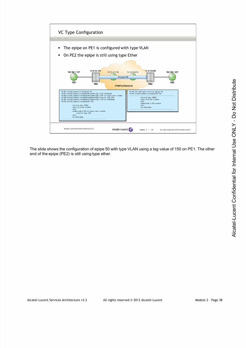
7/21/2019 Services Architecture v3.2 Student Guide Download
http://slidepdf.com/reader/full/services-architecture-v32-student-guide-download 139/429
Alcatel-Lucent Services Architecture v3.2 All rights reserved © 2012 Alcatel-Lucent Module 2 – Page 38
Module 2 | 38 A ll r ights re se rved ©2012 A lcatel -LucentAlcatel-Lucent Services Architecture v3.2
VC Type Configuration
The epipe on PE1 is configured with type VLAN
On PE2 the epipe is still using type Ether
*A:PE-1>conf i g>servi ce# epi pe 50*A:PE-1>conf i g>servi ce>epipe#s poke-sdp 2:50 shutdown*A:PE-1>conf i g>servi ce>epipe#s poke-sdp 2:50 vc-t ype vl an create*A: PE-1>confi g>serv i ce>epipe>spoke-sdp# vl an-vc- t ag 150*A: PE-1>confi g>serv i ce>epipe# spoke-s dp 2: 50 no shutdown*A:PE-1>conf i g>servi ce>epipe#i nfo- - - - - - - - - - - - - - - - - - - - - - - - - - - - - - - - - - - - - - - - - - - - - -
service-mtu 9000sap 1/1/ 4:50 createexitspoke-sdp 2:50 vc-type vlan create
vlan-vc-tag 150exitno shut down
- - - - - - - - - - - - - - - - - - - - - - - - - - - - - - - - - - - - - - - - - - - - - -
*A: PE-2# confi gure servi ce epi pe 50*A:PE-2>conf i g>servi ce>epi pe#i nfo- - - - - - - - - - - - - - - - - - - - - - - - - - - - - - - - - - - - - - - - - - - - - -
service-mtu 9000sap 1/1/4:50 createexi tspoke-sdp 1:50 createexi tno shut down
- - - - - - - - - - - - - - - - - - - - - - - - - - - - - - - - - - - - - - - - - - - - - -
The slide shows the configuration of epipe 50 with type VLAN using a tag value of 150 on PE1. The other
end of the epipe (PE2) is still using type ether.

7/21/2019 Services Architecture v3.2 Student Guide Download
http://slidepdf.com/reader/full/services-architecture-v32-student-guide-download 140/429
Alcatel-Lucent Services Architecture v3.2 All rights reserved © 2012 Alcatel-Lucent Module 2 – Page 39
Module 2 | 39 A ll r ights re se rved ©2012 A lcatel -LucentAlcatel-Lucent Services Architecture v3.2
VC Type Configuration (continued)
T-LDP will not make a pseudowire operational unless the VC ID and
VC type match
*A: PE-1# show service i d 50 sdp 2:50 detai l===========================================================================Servi ce Desti nati on Poi nt (Sdp I d : 2:50) Detai l s===========================================================================Sdp I d 2:50 - (10.10.10.2)
- - - - - - - - - - - - - - - - - - - - - -- - - - - - - - - - - - - - - - - - - - - - - - -- - - - - - - - - - - - - - - - - - - - - - - -- - - -Descripti on : (Not Specif i ed)SDP Id : 2:50 Type : SpokeSpok e Descr : ( Not Spec i f i e d)
VC Type : VLAN VC Tag : 150Admi n Path MTU : 0 Oper Path MTU : 9190Far End : 10. 10. 10. 2 Del i v er y : MPLSHash Label : Di sabled
Admi n State : Up Oper State : Down
Ac ct . Pol : None Col l ec t Stat s : Di sa bl e dI ngress Label : 131071 Egress Label : 0Ingr Mac Fltr -I d : n/a Egr Mac Fltr -I d : n/aI n gr I P F l t r - I d : n/a Egr I P Fl t r - I d : n/aIngr IPv6 F l t r - Id : n/a Egr IPv6 F l t r - Id : n/aAdmi n Cont r ol Wor d : Not Pr ef er r ed Oper Cont r ol Wor d : F al s eAdmi n BW( Kbps) : 0 Oper BW(Kbps) : 0Last Status Change : 02/10/2012 11:27:18 Signal ing : TLDPLast Mgmt Change : 02/ 10/ 2012 11: 27: 57 Force Vlan-Vc : Di sabl edEndpoi nt : N/ A Pr ecedence : 4Cl ass Fwding State : DownFlags : NoEgrVCLabel
Peer Pw Bits : NonePeer Faul t I p : None…
*A:PE-1# show service servi ce-using epi pe======================================================Servi ces [epipe]======================================================ServiceI d Type Adm Opr CustomerId Service Name- - - - - - - - - - - - - - - - - - - - - - - - - - - - - - - - - - - - - - - - - - - - - - - - - - - - - -50 Epi pe Up Down 100- - - - - - - - - - - - - - - - - - - - - - - - - - - - - - - - - - - - - - - - - - - - - - - - - - - - - -Matchi ng Servi ces : 1
T-LDP will not make a pseudowire operational unless the VC ID and VC type match. The Flags field
contains NoEgrVCLabel, which is an indication that there is no service at the other end.

7/21/2019 Services Architecture v3.2 Student Guide Download
http://slidepdf.com/reader/full/services-architecture-v32-student-guide-download 141/429
Alcatel-Lucent Services Architecture v3.2 All rights reserved © 2012 Alcatel-Lucent Module 2 – Page 40
Module 2 | 40 A ll r ights re se rved ©2012 A lcatel -LucentAlcatel-Lucent Services Architecture v3.2
VC Type Configuration (continued)
T-LDP will not make a pseudowire operational unless the VC ID and
VC type match
*A:PE-1# showrouter l dp bi ndings fec-type services
===============================================================================LDP LSR I D: 10. 10.10. 1===============================================================================Legend: U - Label I n Use, N - Label Not I n Use, W - Label Wi thdrawn
S - Status Signaled Up, D - Status Signaled DownE - Epipe Service, V - VPLS Service, M - Mir ror Servi ceA - Apipe Service, F - Fpipe Service, I - IES Service, R - VPRN serviceP - I pipe Service, WP - Label Wit hdraw Pendi ng, C - Cpipe Service
TLV - (Type, Length: Value)===============================================================================LDP Servi ce FEC 128 Bi ndings===============================================================================
Type VCI d SvcI d SDPI d Peer I ngLbl EgrLbl LMTU RMTU- - - - - - - - - - - - - - - - - - - - - - -- - - - - - - - - - - - - - - - - - - - - - - - -- - - - - - - - - - - - - - - - - - - - - - - -- - - - - - -E-Vlan 50 50 2 10. 10. 10.2 131071U -- 8986 0?-Eth 50 Ukwn R. Sr c 10. 1 0. 1 0. 2 - - 131071S 0 8986- - - - - - - - - - - - - - - - - - - - - - -- - - - - - - - - - - - - - - - - - - - - - - - -- - - - - - - - - - - - - - - - - - - - - - - -- - - - - - -No. of VC Labels : 2
The show router ldp bindings fec-type services command shows two different services with VC ID of
50 but different VC types.

7/21/2019 Services Architecture v3.2 Student Guide Download
http://slidepdf.com/reader/full/services-architecture-v32-student-guide-download 142/429
Alcatel-Lucent Services Architecture v3.2 All rights reserved © 2012 Alcatel-Lucent Module 2 – Page 41
Module 2 | 41 A ll r ights re se rved ©2012 A lcatel -LucentAlcatel-Lucent Services Architecture v3.2
VC Type Configuration (continued)
Configure the epipe on PE2 with type VLAN
*A: PE-2# confi gure servi ce epi pe 50*A:PE-2>conf i g>servi ce>epipe#s poke-sdp 1:50 shutdown*A:PE-2>conf i g>servi ce>epipe#s poke-sdp 1:50 vc-t ype vl an create*A: PE-2>confi g>servi ce>epipe>spoke-sdp# vl an-vc- t ag 150*A: PE-2>confi g>servi ce>epipe>spoke-sdp# no shutdown*A: PE-2>confi g>servi ce>epipe>spoke-sdp# exi t*A:PE-2>conf i g>servi ce>epipe#i nfo- - - - - - - - - - - - - - - - - - - - - - - - - - - - - - - - - - - - - - - - - - - - - -
service-mtu 9000sap 1/1/ 4:50 createexitspoke-sdp 1:50 vc-type vlan create
vlan-vc-tag 150exitno shut down
- - - - - - - - - - - - - - - - - - - - - - - - - - - - - - - - - - - - - - - - - - - - - -
The remote router (PE2) is configured as type VLAN.
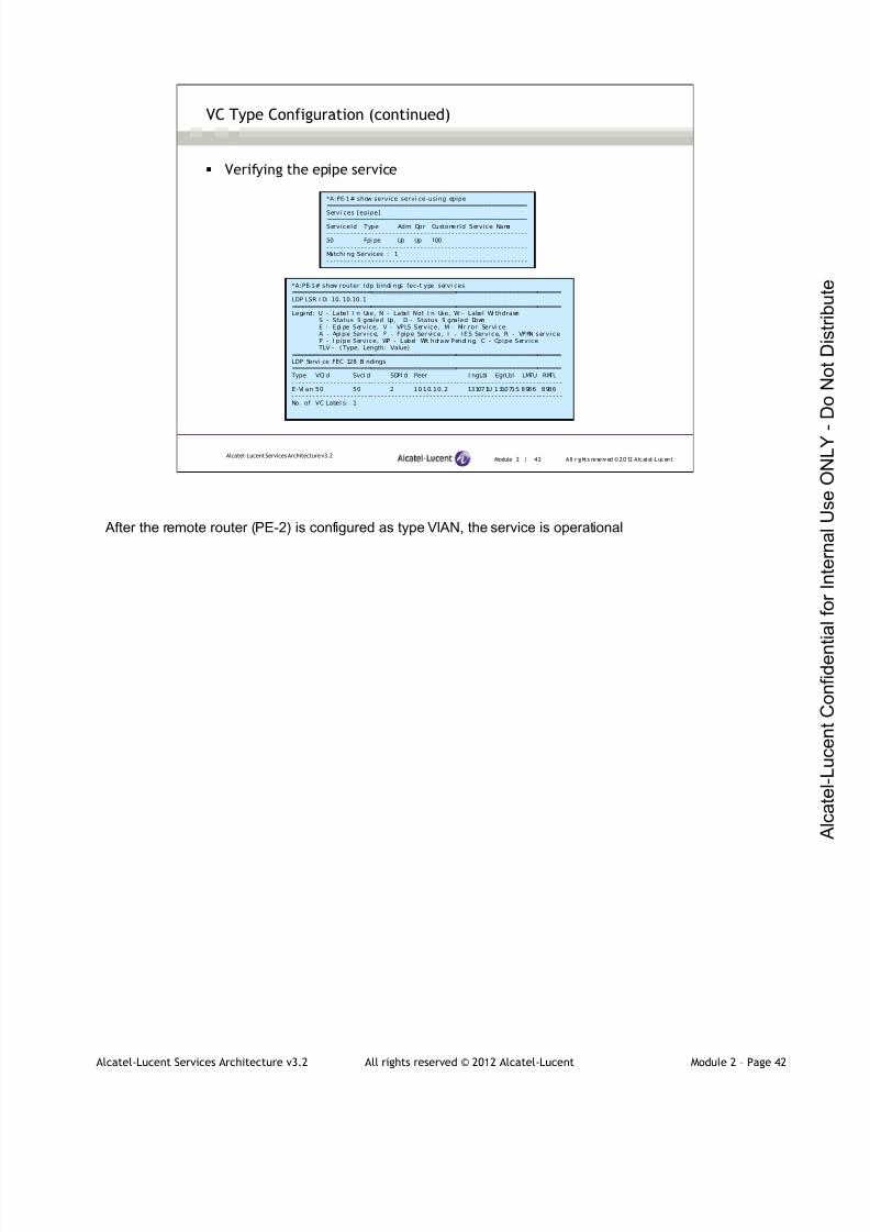
7/21/2019 Services Architecture v3.2 Student Guide Download
http://slidepdf.com/reader/full/services-architecture-v32-student-guide-download 143/429
Alcatel-Lucent Services Architecture v3.2 All rights reserved © 2012 Alcatel-Lucent Module 2 – Page 42
Module 2 | 42 A ll r ights re se rved ©2012 A lcatel -LucentAlcatel-Lucent Services Architecture v3.2
VC Type Configuration (continued)
Verifying the epipe service
*A:PE-1# show service servi ce-using epipe==========================================================
Servi ces [epipe]==========================================================ServiceId Type Adm Opr CustomerId Service Name- - - - - - - - - - - - - - - - - - - - - - - - - - - - - - - - - - - - - - - - - - - - - - - - - - - - - - - - - -50 Epi pe Up Up 100- - - - - - - - - - - - - - - - - - - - - - - - - - - - - - - - - - - - - - - - - - - - - - - - - - - - - - - - - -Matchi ng Services : 1- - - - - - - - - - - - - - - - - - - - - - - - - - - - - - - - - - - - - - - - - - - - - - - - - - - - - - - - - -
*A:PE-1# show router ldp bindi ngs fec-t ype servi ces===============================================================================LDP LSR I D: 10. 10.10. 1===============================================================================Legend: U - Label I n Use, N - Label Not I n Use, W - Label Wi thdrawn
S - Status Si gnaled Up, D - Status Si gnaled DownE - Epi pe Service, V - VPLS Service, M - Mir ror Servi ceA - Apipe Service, F - Fpipe Service, I - IES Service, R - VPRN serviceP - I pipe Service, WP - Label Wit hdraw Pendi ng, C - Cpipe Service
TLV - ( Type, Length: Value)===============================================================================LDP Servi ce FEC 128 Bi ndings===============================================================================
Type VCI d SvcI d SDPI d Peer I ngLbl EgrLbl LMTU RMTU- - - - - - - - - - - - - - - - - - - - - - -- - - - - - - - - - - - - - - - - - - - - - - - -- - - - - - - - - - - - - - - - - - - - - - - -- - - - - - -E-Vl an 50 50 2 10.10.10.2 131071U 131071S 8986 8986- - - - - - - - - - - - - - - - - - - - - - -- - - - - - - - - - - - - - - - - - - - - - - - -- - - - - - - - - - - - - - - - - - - - - - - -- - - - - - -No. of VC Label s: 1
After the remote router (PE-2) is configured as type VlAN, the service is operational

7/21/2019 Services Architecture v3.2 Student Guide Download
http://slidepdf.com/reader/full/services-architecture-v32-student-guide-download 144/429
Alcatel-Lucent Services Architecture v3.2 All rights reserved © 2012 Alcatel-Lucent Module 2 – Page 43
Module 2 | 43 A ll r ights re se rved ©2012 A lcatel -LucentAlcatel-Lucent Services Architecture v3.2
VLAN Tag Behavior With a Null SAP
The slide shows the different combinations of frame transmission possible for a null encapsulated SAP
with different egress encapsulations. The behavior of the default dot1Q SAP is the same.
Notice in the diagram above:
VLAN tags received on a customer SAP port are never considered by null SAPs to be service delimiting.
Therefore, ingress VLAN tags are passed transparently through the network from ingress SAP to egress
SAP. Since these tags are not considered to be service delimiting, in VC type VLAN mode, we will always
add a dummy tag with default VLAN ID = 0.
Note: on the egress SAP, the tags configured on the SAP always encapsulate the frame, including any
VLAN tag received.
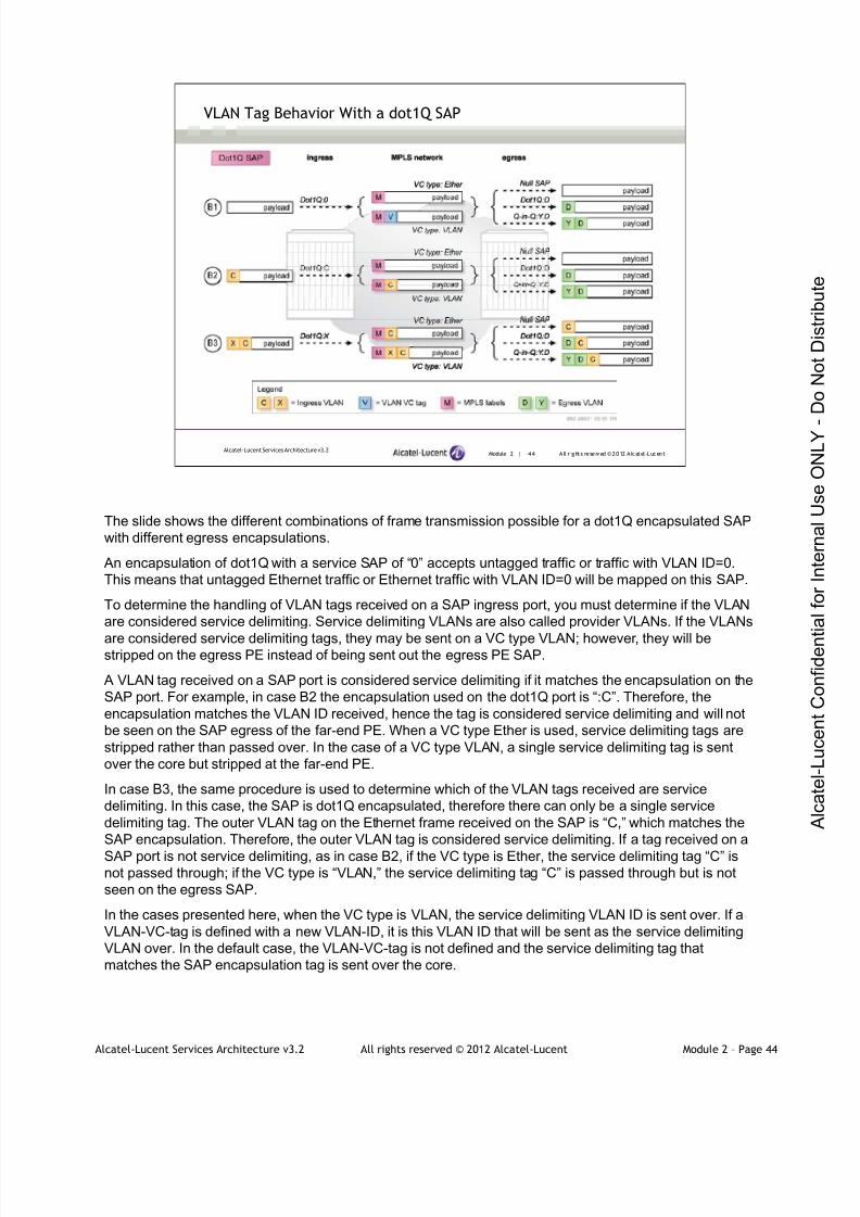
7/21/2019 Services Architecture v3.2 Student Guide Download
http://slidepdf.com/reader/full/services-architecture-v32-student-guide-download 145/429
Alcatel-Lucent Services Architecture v3.2 All rights reserved © 2012 Alcatel-Lucent Module 2 – Page 44
Module 2 | 44 A ll r ights re se rved ©2012 A lcatel -LucentAlcatel-Lucent Services Architecture v3.2
VLAN Tag Behavior With a dot1Q SAP
The slide shows the different combinations of frame transmission possible for a dot1Q encapsulated SAP
with different egress encapsulations.
An encapsulation of dot1Q with a service SAP of “0” accepts untagged traffic or traffic with VLAN ID=0.
This means that untagged Ethernet traffic or Ethernet traffic with VLAN ID=0 will be mapped on this SAP.
To determine the handling of VLAN tags received on a SAP ingress port, you must determine if the VLAN
are considered service delimiting. Service delimiting VLANs are also called provider VLANs. If the VLANs
are considered service delimiting tags, they may be sent on a VC type VLAN; however, they will bestripped on the egress PE instead of being sent out the egress PE SAP.
A VLAN tag received on a SAP port is considered service delimiting if it matches the encapsulation on the
SAP port. For example, in case B2 the encapsulation used on the dot1Q port is “:C”. Therefore, the
encapsulation matches the VLAN ID received, hence the tag is considered service delimiting and will not
be seen on the SAP egress of the far-end PE. When a VC type Ether is used, service delimiting tags are
stripped rather than passed over. In the case of a VC type VLAN, a single service delimiting tag is sent
over the core but stripped at the far-end PE.
In case B3, the same procedure is used to determine which of the VLAN tags received are service
delimiting. In this case, the SAP is dot1Q encapsulated, therefore there can only be a single service
delimiting tag. The outer VLAN tag on the Ethernet frame received on the SAP is “C,” which matches the
SAP encapsulation. Therefore, the outer VLAN tag is considered service delimiting. If a tag received on a
SAP port is not service delimiting, as in case B2, if the VC type is Ether, the service delimiting tag “C” isnot passed through; if the VC type is “VLAN,” the service delimiting tag “C” is passed through but is not
seen on the egress SAP.
In the cases presented here, when the VC type is VLAN, the service delimiting VLAN ID is sent over. If a
VLAN-VC-tag is defined with a new VLAN-ID, it is this VLAN ID that will be sent as the service delimiting
VLAN over. In the default case, the VLAN-VC-tag is not defined and the service delimiting tag that
matches the SAP encapsulation tag is sent over the core.

7/21/2019 Services Architecture v3.2 Student Guide Download
http://slidepdf.com/reader/full/services-architecture-v32-student-guide-download 146/429
Alcatel-Lucent Services Architecture v3.2 All rights reserved © 2012 Alcatel-Lucent Module 2 – Page 45
Module 2 | 45 A ll r ights re se rved ©2012 A lcatel -LucentAlcatel-Lucent Services Architecture v3.2
VLAN Tag Behavior With a Q-in-Q SAP
In the cases presented here, when the VC type is VLAN, the service delimiting VLAN ID is sent over. If a
VLAN-VC-tag is defined with a new VLAN-ID, it is this VLAN ID that will be sent as the service delimiting
VLAN. In the default case, the VLAN-VC-tag is not defined and the service delimiting tag that matches the
SAP encapsulation tag is used.

7/21/2019 Services Architecture v3.2 Student Guide Download
http://slidepdf.com/reader/full/services-architecture-v32-student-guide-download 147/429
Alcatel-Lucent Services Architecture v3.2 All rights reserved © 2012 Alcatel-Lucent Module 2 – Page 46
Module 2 | 46 A ll r ights re se rved ©2012 A lcatel -LucentAlcatel-Lucent Services Architecture v3.2
Encapsulation and VC Type Summary
An epipe can be configured with any combination of SAP encapsulation at
each end
Null SAP or default dot1Q SAP (SAP 1/1/1, SAP 1/1/1:*)
All VLAN tags received at ingress are transmitted in the pseudowire. NoVLAN tags are added to egressing packets
Dot1Q SAP or wildcard Q-in-Q SAP (SAP 1/1/1:10, SAP 1/1/1:10.*)
Outer VLAN tag is removed at ingress, and any remaining tags aretransmitted in the pseudowire
The specified VLAN tag is added to packets on egress
Q-in-Q SAP (SAP 1/1/1:10:20)
Two outer VLAN tags are removed at ingress
The two specified VLAN tags are added to egressing packets
There are many options for SAP encapsulations as well as two options for the VC type on an Ethernet
pseudowire.
An epipe can be configured with any combination of SAP encapsulation at each end; a null SAP on one
side and a Q-in-Q encapsulated SAP on the other side, for example.

7/21/2019 Services Architecture v3.2 Student Guide Download
http://slidepdf.com/reader/full/services-architecture-v32-student-guide-download 148/429
Alcatel-Lucent Services Architecture v3.2 All rights reserved © 2012 Alcatel-Lucent Module 2 – Page 47
Module 2 | 47 A ll r ights re se rved ©2012 A lcatel -LucentAlcatel-Lucent Services Architecture v3.2
Encapsulation Summary — dot1Q
Explicitly matched VLAN tags are stripped on the ingress PE when the SDP
VC type is set to "Ether“
The VLAN tag may be regenerated at the egress PE depending on how
the SAP is configured
SAP:0, only untagged frames and/or a VLAN of 0 are accepted
SAP:*, allows untagged frames and tagged frames with any VLAN ID that
has not been explicitly defined on the port
Examples:
When a SAP is defined with the 1/1/1:0, any untagged frames and/or frames with a tag of “0” are
accepted.
When a SAP is defined with a wild card (SAP 1/1/1:*), the default SAP will allow untagged frames and
tagged frames with any VLAN ID that has not been explicitly defined on port 1/1/1.

7/21/2019 Services Architecture v3.2 Student Guide Download
http://slidepdf.com/reader/full/services-architecture-v32-student-guide-download 149/429
Alcatel-Lucent Services Architecture v3.2 All rights reserved © 2012 Alcatel-Lucent Module 2 – Page 48
Module 2 | 48 A ll r ights re se rved ©2012 A lcatel -LucentAlcatel-Lucent Services Architecture v3.2
Encapsulation Summary — Q-in-Q
Explicitly matched tag (SAP:Top:Bottom) is stripped at ingress when the VC
type on the SDP is set to “Ether,” and regenerated at egress depending on
how the egress SAP is configured
SAP:top.* strips the top VLAN tag and preserves the bottom (MTU
implications)
Will also accept no bottom tag
SAP:0.* matches untagged and/or a VLAN of 0 for the top tag
Examples
SAP 1/1/1:0.* — Will allow any untagged frames and/or frames with a top tag of “0” only.
SAP 1/1/1:10.* — Will only match “10” as the top Q tag and may have any bottom tag or no bottom tag at
all.
SAP 1/1/1:10.0 — Will only match “10” as the top Q tag and may have a bottom tag of 0 or no bottom tag
at all.
SAP 1/1/1:10.* and 1/1/1:10.0 — Co-exist in the same service: traffic with a top tag of “10” will always belearned from SAP 1/1/1:10.0
SAP 1/1/1:10.11 — Will only match packets with an existing top and bottom tag, in this case the top tag is
“10” and the bottom tag is “11.”

7/21/2019 Services Architecture v3.2 Student Guide Download
http://slidepdf.com/reader/full/services-architecture-v32-student-guide-download 150/429
Alcatel-Lucent Services Architecture v3.2 All rights reserved © 2012 Alcatel-Lucent Module 2 – Page 49
Module 2 | 49 A ll r ights re se rved ©2012 A lcatel -LucentAlcatel-Lucent Services Architecture v3.2
Lab 2 ― Distributed Epipe Service
In this lab you will configure and verify an epipe service.

7/21/2019 Services Architecture v3.2 Student Guide Download
http://slidepdf.com/reader/full/services-architecture-v32-student-guide-download 151/429
Alcatel-Lucent Services Architecture v3.2 All rights reserved © 2012 Alcatel-Lucent Module 2 – Page 50
Alcatel-Lucent Services Architecture
Section 2 — Other VPWS
7/21/2019 Services Architecture v3.2 Student Guide Download
http://slidepdf.com/reader/full/services-architecture-v32-student-guide-download 152/429
Alcatel-Lucent Services Architecture v3.2 All rights reserved © 2012 Alcatel-Lucent Module 2 – Page 51
Module 2 | 51 A ll r ights re se rved ©2012 A lcatel -LucentAlcatel-Lucent Services Architecture v3.2
Section Objectives
After successfully completing this section, you will be able to:
Describe the main characteristics of fpipe service
Describe the main characteristics of apipe service
Describe the two modes of operation supported on the Alcatel-
Lucent 7750 SR for apipe
Describe the main characteristics of cpipe service
In the previous section we described the epipe service in detail, and throughout this course most of the
attention to Layer 2 services is given to Ethernet. Other Layer 2 services supported by the Alcatel-Lucent
7750SR are also important. Although the trend in current network deployments is increasingly to Ethernet
for reasons of cost and performance, there is still a very significant demand for other technologies that
represent very significant revenues to service providers. These services can be deployed on an IP/MPLS
infrastructure that simultaneously provides a base for modern Ethernet and IP services. Layer 2 services
available besides Ethernet (epipe) are fpipe, apipe, cpipe and ipipe (ipipe will be covered in the next
section).
These services are all based on RFC 4447 (Pseudowire Setup and Maintenance Using LDP) and most of
the characteristics, configuration and maintenance that we describe for epipes apply to these services as
well. In this section we introduce each of these services, paying particular attention to any characteristics
that distinguish them from an epipe service.

7/21/2019 Services Architecture v3.2 Student Guide Download
http://slidepdf.com/reader/full/services-architecture-v32-student-guide-download 153/429
Alcatel-Lucent Services Architecture v3.2 All rights reserved © 2012 Alcatel-Lucent Module 2 – Page 52
Module 2 | 52 A ll r ights re se rved ©2012 A lcatel -LucentAlcatel-Lucent Services Architecture v3.2
Fpipe Service
Fpipe provides a point-to-point Frame Relay service between users
connected to 7750SR routers on the IP/MPLS network
A single Frame Relay circuit is mapped to an fpipe service
From the customer’s perspective, the PE router should appear as a native
Frame Relay UNI (user network interface)
The control word is required for an fpipe because the Frame Relay header is
not carried with the encapsulated frame
In the past, VPN markets were dominated by both Frame Relay and private lines, which dominated
approximately 90 percent of enterprise connections. The popularity of Frame Relay service over a private
line is based on the lower cost of Frame Relay as well as its ability to support large amounts of traffic.
However, growth in Frame Relay services is limited by its lower speed and the cost of multipoint solutions.
For service providers with established Frame Relay services, the MPLS network allows them to leverage
their existing infrastructure to enable new revenue opportunities. These new revenue opportunities are
created by blending technologies through service interworking in order to create a service hybrid. For the
enterprise that is seeking a gradual transition from a Frame Relay VPN to an Ethernet VPWS or whowants to add a new site with Ethernet access while still maintaining Frame Relay at the other sites, a
service hybrid is ideal.
UNI: user network interface.
Frame Relay pseudowires are described in RFC 4619 (Encapsulation Methods for Transport of Frame
Relay Over MPLS Networks). The 7750 SR supports one-to-one mode for the mapping of a Frame Relay
DLCI (data link connection identifier) to a pseudowire. This means that a single Frame Relay circuit is
mapped to an fpipe service.
From the customer’s perspective, the PE router should appear as much as possible like a native Frame
Relay UNI (user network interface).
When a frame arrives at the fpipe SAP, the Frame Relay header and any padding are removed. The frame
is encapsulated with a service label and transport label as for any pseudowire service. The fpipe also usesthe MPLS control word, which is a 4-byte field directly following the service label. Specific values from the
Frame Relay header are copied into the control word.
The MPLS control word is an optional field in the RFC 4447 pseudowire encapsulation. It is not generally
used in an epipe, but is always present in the fpipe encapsulation.
The control word is required for an fpipe because the Frame Relay header is not carried with the
encapsulated frame. When the frame is received at the ingress SAP, specific bits are copied to the control
word. When the Frame Relay frame is reconstructed at the egress SAP these bits are copied to the
appropriate bit in the header.

7/21/2019 Services Architecture v3.2 Student Guide Download
http://slidepdf.com/reader/full/services-architecture-v32-student-guide-download 154/429
Alcatel-Lucent Services Architecture v3.2 All rights reserved © 2012 Alcatel-Lucent Module 2 – Page 53
Module 2 | 53 A ll r ights re se rved ©2012 A lcatel -LucentAlcatel-Lucent Services Architecture v3.2
Fpipe Common Configuration Tasks
The fpipe uses the same provisioning steps as an epipe, with the
following exceptions:
The service type is fpipe The physical port or channel is a SONET port set for Frame Relay
framing
SAP is in the form of port:DLCI (example – 1/1/1:65)
There is no Frame Relay MDA. Frame Relay encapsulation is supported on all MDAs that support POS
encapsulation.
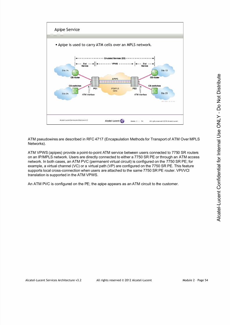
7/21/2019 Services Architecture v3.2 Student Guide Download
http://slidepdf.com/reader/full/services-architecture-v32-student-guide-download 155/429
Alcatel-Lucent Services Architecture v3.2 All rights reserved © 2012 Alcatel-Lucent Module 2 – Page 54
ATM pseudowires are described in RFC 4717 (Encapsulation Methods for Transport of ATM Over MPLS
Networks).
ATM VPWS (apipes) provide a point-to-point ATM service between users connected to 7750 SR routers
on an IP/MPLS network. Users are directly connected to either a 7750 SR PE or through an ATM access
network. In both cases, an ATM PVC (permanent virtual circuit) is configured on the 7750 SR PE; for
example, a virtual channel (VC) or a virtual path (VP) are configured on the 7750 SR PE. This feature
supports local cross-connection when users are attached to the same 7750 SR PE router. VPI/VCItranslation is supported in the ATM VPWS.
An ATM PVC is configured on the PE; the apipe appears as an ATM circuit to the customer.
Module 2 | 54 A ll r ights re se rved ©2012 A lcatel -LucentAlcatel-Lucent Services Architecture v3.2
Apipe Service
Apipe is used to carry ATM cells over an MPLS network.
7/21/2019 Services Architecture v3.2 Student Guide Download
http://slidepdf.com/reader/full/services-architecture-v32-student-guide-download 156/429
Alcatel-Lucent Services Architecture v3.2 All rights reserved © 2012 Alcatel-Lucent Module 2 – Page 55
Module 2 | 55 A ll r ights re se rved ©2012 A lcatel -LucentAlcatel-Lucent Services Architecture v3.2
Apipe Service – Modes of Operation
Supported apipe modes of operation:
N:1 cell mode:
Individual cells or groups of cells are encapsulated for transmission onthe apipe
ATM Adaptation Layer 5 (AAL5) frame mode:
An AAL5 SDU (service delivery unit) frame is encapsulated for
transmission on the apipe
Two different modes of operation are supported on the Alcatel-Lucent 7750 SR for ATM apipes: the N:1
cell mode and AAL5 frame mode.
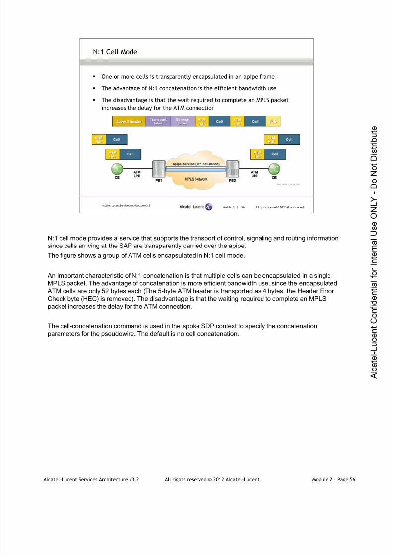
7/21/2019 Services Architecture v3.2 Student Guide Download
http://slidepdf.com/reader/full/services-architecture-v32-student-guide-download 157/429
Alcatel-Lucent Services Architecture v3.2 All rights reserved © 2012 Alcatel-Lucent Module 2 – Page 56
Module 2 | 56 A ll r ights re se rved ©2012 A lcatel -LucentAlcatel-Lucent Services Architecture v3.2
N:1 Cell Mode
One or more cells is transparently encapsulated in an apipe frame
The advantage of N:1 concatenation is the efficient bandwidth use
The disadvantage is that the wait required to complete an MPLS packet
increases the delay for the ATM connection
N:1 cell mode provides a service that supports the transport of control, signaling and routing information
since cells arriving at the SAP are transparently carried over the apipe.
The figure shows a group of ATM cells encapsulated in N:1 cell mode.
An important characteristic of N:1 concatenation is that multiple cells can be encapsulated in a single
MPLS packet. The advantage of concatenation is more efficient bandwidth use, since the encapsulated
ATM cells are only 52 bytes each (The 5-byte ATM header is transported as 4 bytes, the Header ErrorCheck byte (HEC) is removed). The disadvantage is that the waiting required to complete an MPLS
packet increases the delay for the ATM connection.
The cell-concatenation command is used in the spoke SDP context to specify the concatenation
parameters for the pseudowire. The default is no cell concatenation.

7/21/2019 Services Architecture v3.2 Student Guide Download
http://slidepdf.com/reader/full/services-architecture-v32-student-guide-download 158/429
Alcatel-Lucent Services Architecture v3.2 All rights reserved © 2012 Alcatel-Lucent Module 2 – Page 57
Module 2 | 57 A ll r ights re se rved ©2012 A lcatel -LucentAlcatel-Lucent Services Architecture v3.2
AAL5 Frame Mode
AAL5 was defined for a best effort, connectionless packet service such as IP
The control word is required for an apipe in AAL5 frame mode
Allows ATM AAL5 PDUs traveling on a particular ATM PVC across the network
to travel to another ATM PVC
Requires segmentation and reassembly on the ingress PE-CE ATM interface
Once reassembled, the AAL5-SDU is carried through a pseudowire to the
egress PE
The AAL5 SDU (service delivery unit) is the payload that the service is intended to carry - in this case, the
IP packet. The SDU is encapsulated in an AAL5 PDU, which has no header but an 8-byte trailer, and is
padded so that the SDU + trailer + padding is an exact multiple of 48 bytes long. The AAL5 PDU is then
split into the necessary number of cells for transmission. This operation is known as segmentation and
reassembly (SAR).

7/21/2019 Services Architecture v3.2 Student Guide Download
http://slidepdf.com/reader/full/services-architecture-v32-student-guide-download 159/429
Alcatel-Lucent Services Architecture v3.2 All rights reserved © 2012 Alcatel-Lucent Module 2 – Page 58
Module 2 | 58 A ll r ights re se rved ©2012 A lcatel -LucentAlcatel-Lucent Services Architecture v3.2
AAL5 Frame Mode Operation
The AAL5 SDU (service delivery unit) is the payload that the service is intended to carry - in this case, the
IP packet. The SDU is encapsulated in an AAL5 PDU, which has no header but an 8-byte trailer, and is
padded so that the SDU + trailer + padding is an exact multiple of 48 bytes long. The AAL5 PDU is then
split into the necessary number of cells for transmission. This operation is known as segmentation and
reassembly (SAR).
When the apipe is defined as VC type atm-sdu, the PEs perform the SAR operation and only the AAL5
SDU is carried in the MPLS-encapsulated packet. This provides more efficient use of the bandwidth, since
the AAL5 overhead (padding and trailer) and the ATM cell headers are discarded.
The SAP defines a single PVC in the format port:pvi/pci.
As in the fpipe, the control word is also required for an apipe in AAL5 frame mode. The purpose is to carry
the information lost when the cell headers are stripped in the SAR process.
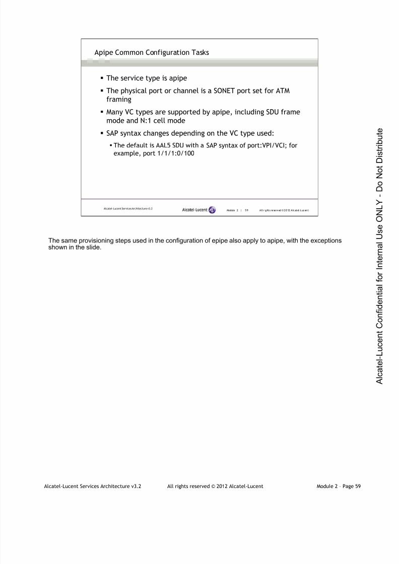
7/21/2019 Services Architecture v3.2 Student Guide Download
http://slidepdf.com/reader/full/services-architecture-v32-student-guide-download 160/429
Alcatel-Lucent Services Architecture v3.2 All rights reserved © 2012 Alcatel-Lucent Module 2 – Page 59
Module 2 | 59 A ll r ights re se rved ©2012 A lcatel -LucentAlcatel-Lucent Services Architecture v3.2
Apipe Common Configuration Tasks
The service type is apipe
The physical port or channel is a SONET port set for ATM
framing
Many VC types are supported by apipe, including SDU frame
mode and N:1 cell mode
SAP syntax changes depending on the VC type used:
The default is AAL5 SDU with a SAP syntax of port:VPI/VCI; for
example, port 1/1/1:0/100
The same provisioning steps used in the configuration of epipe also apply to apipe, with the exceptionsshown in the slide.

7/21/2019 Services Architecture v3.2 Student Guide Download
http://slidepdf.com/reader/full/services-architecture-v32-student-guide-download 161/429
Alcatel-Lucent Services Architecture v3.2 All rights reserved © 2012 Alcatel-Lucent Module 2 – Page 60
Circuit Emulation Services (CES) VPWS or Cpipe, is a point-to-point VPN service emulating a TDM
leased line. Two PE routers connected to the customer sites through the local attachment circuit receive
native TDM traffic, perform both VPN (PW) and transport tunnel encapsulation, and finally send the traffic
through the packet-switched network to reach the remote site. The packet-switched network is PSN,
usually IP/MPLS.
Cpipes are an implementation of TDM pseudowires to transport T1 or E1 circuits. T-1 is a digital circuit
that uses the DS-1 (Digital Signaling level 1) signaling format to transmit voice/data over the PSTN
network at 1.544 Mbps. T-1 can carry up to 24 uncompressed digital channels of 64 Kbps (DS0) for voice
or data. E-1 is the European equivalent of the T-1, except E-1 carries information at the rate of 2.048
Mbps. E-1 is used to transmit 30 64Kbps digital channels (DS0) for voice or data calls, plus a 64Kbps
channel for signaling, and a 64Kbps channel for framing and maintenance.
Module 2 | 60 A ll r ights re se rved ©2012 A lcatel -LucentAlcatel-Lucent Services Architecture v3.2
Cpipe Service
TDM VPWS (cpipe) is used to carry TDM frames over an IP/MPLS
network
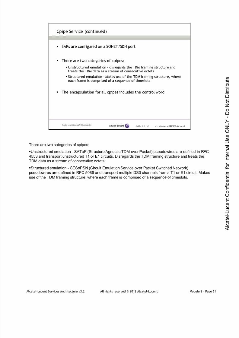
7/21/2019 Services Architecture v3.2 Student Guide Download
http://slidepdf.com/reader/full/services-architecture-v32-student-guide-download 162/429
Alcatel-Lucent Services Architecture v3.2 All rights reserved © 2012 Alcatel-Lucent Module 2 – Page 61
Module 2 | 61 A ll r ights re se rved ©2012 A lcatel -LucentAlcatel-Lucent Services Architecture v3.2
Cpipe Service (continued)
SAPs are configured on a SONET/SDH port
There are two categories of cpipes:
Unstructured emulation - disregards the TDM framing structure andtreats the TDM data as a stream of consecutive octets
Structured emulation - Makes use of the TDM framing structure, whereeach frame is comprised of a sequence of timeslots
The encapsulation for all cpipes includes the control word
There are two categories of cpipes:
Unstructured emulation - SAToP (Structure Agnostic TDM over Packet) pseudowires are defined in RFC
4553 and transport unstructured T1 or E1 circuits. Disregards the TDM framing structure and treats the
TDM data as a stream of consecutive octets
Structured emulation - CESoPSN (Circuit Emulation Service over Packet Switched Network)
pseudowires are defined in RFC 5086 and transport multiple DS0 channels from a T1 or E1 circuit. Makes
use of the TDM framing structure, where each frame is comprised of a sequence of timeslots.
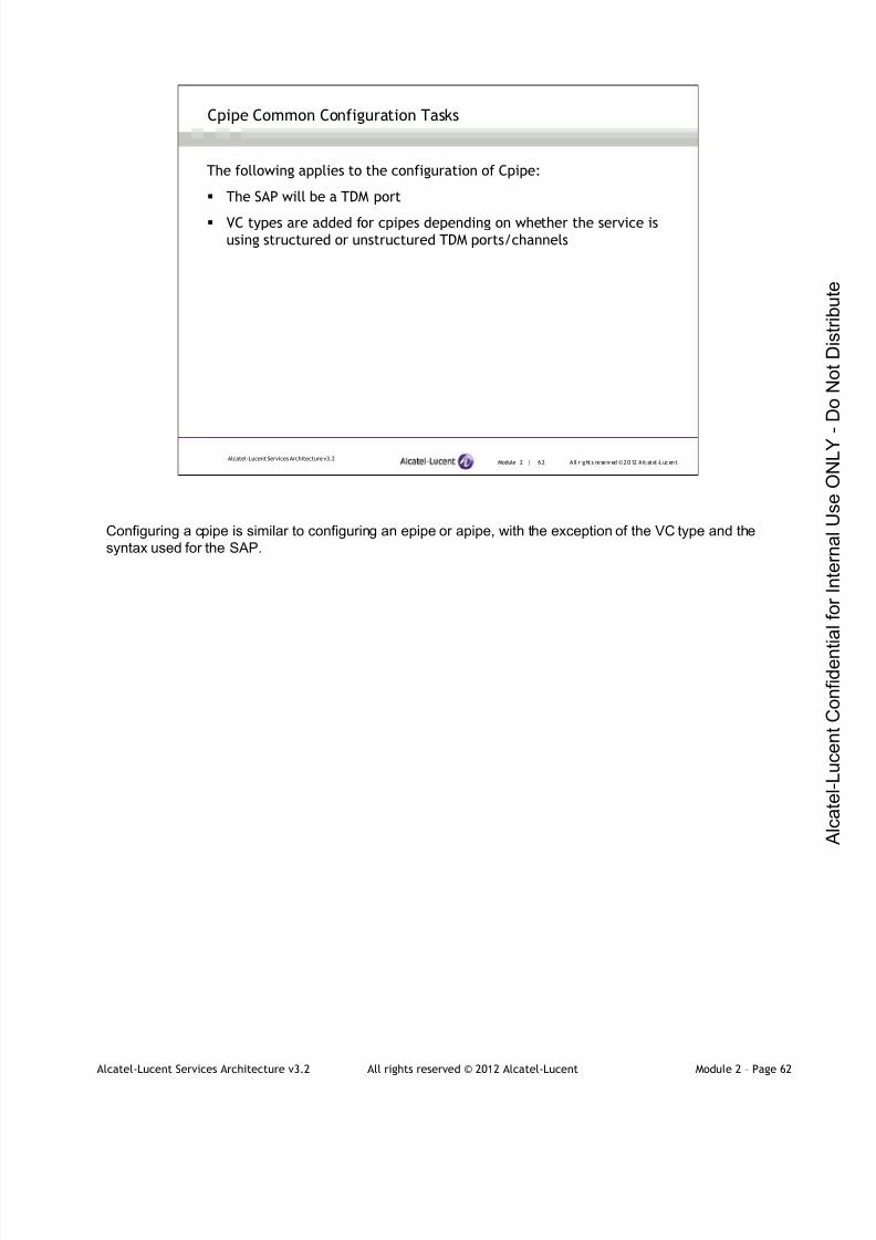
7/21/2019 Services Architecture v3.2 Student Guide Download
http://slidepdf.com/reader/full/services-architecture-v32-student-guide-download 163/429
Alcatel-Lucent Services Architecture v3.2 All rights reserved © 2012 Alcatel-Lucent Module 2 – Page 62
Module 2 | 62 A ll r ights re se rved ©2012 A lcatel -LucentAlcatel-Lucent Services Architecture v3.2
Cpipe Common Configuration Tasks
The following applies to the configuration of Cpipe:
The SAP will be a TDM port
VC types are added for cpipes depending on whether the service isusing structured or unstructured TDM ports/channels
Configuring a cpipe is similar to configuring an epipe or apipe, with the exception of the VC type and the
syntax used for the SAP.

7/21/2019 Services Architecture v3.2 Student Guide Download
http://slidepdf.com/reader/full/services-architecture-v32-student-guide-download 164/429
Alcatel-Lucent Services Architecture v3.2 All rights reserved © 2012 Alcatel-Lucent Module 2 – Page 63
Alcatel-Lucent Services Architecture
Section 3 — VPWS Interworking Capabilities

7/21/2019 Services Architecture v3.2 Student Guide Download
http://slidepdf.com/reader/full/services-architecture-v32-student-guide-download 165/429
Alcatel-Lucent Services Architecture v3.2 All rights reserved © 2012 Alcatel-Lucent Module 2 – Page 64
Module 2 | 64 A ll r ights re se rved ©2012 A lcatel -LucentAlcatel-Lucent Services Architecture v3.2
Section Objectives
After successfully completing this section, you will be able to:
Identify the 7750 SR interworking capabilities provided with VPWS
Define ipipe service and explain its main characteristics

7/21/2019 Services Architecture v3.2 Student Guide Download
http://slidepdf.com/reader/full/services-architecture-v32-student-guide-download 166/429
Alcatel-Lucent Services Architecture v3.2 All rights reserved © 2012 Alcatel-Lucent Module 2 – Page 65
Module 2 | 65 A ll r ights re se rved ©2012 A lcatel -LucentAlcatel-Lucent Services Architecture v3.2
Interworking VPWS
The interworking capabilities of the 7750 SR are:
ATM Frame Relay Ethernet
ATM Apipe Apipe (FRF.5 interworking)Epipe (bridged)Ipipe (routed)
Frame Relay Apipe (FRF.5 interworking) FpipeEpipe (bridged)Ipipe (routed)
EthernetEpipe (bridged)Ipipe (routed)
Epipe (bridged)Ipipe (routed)
Epipe
The Alcatel-Lucent VPWS offers network interworking for Ethernet, ATM and Frame Relay across a
common IP/MPLS network. The interworking capabilities of the VPWS allow different Layer 2 networks to
be connected together across an IP/MPLS core network.
The table in this slide lists the various interworking scenarios possible with ATM, Frame Relay and
Ethernet ports at either end of a pseudowire.
•When IP traffic, encapsulated inside an Ethernet frame, needs to be transported by a bridge/router over
its ATM port to a bridge/router with an Ethernet port, bridged encapsulation is used. An epipe is requiredto transport this type of traffic.
Routed encapsulation is used when native IP traffic is transported across a bridge/router with an ATM port
to a bridge/router with an Ethernet port. An ipipe is required to transport this type of traffic.
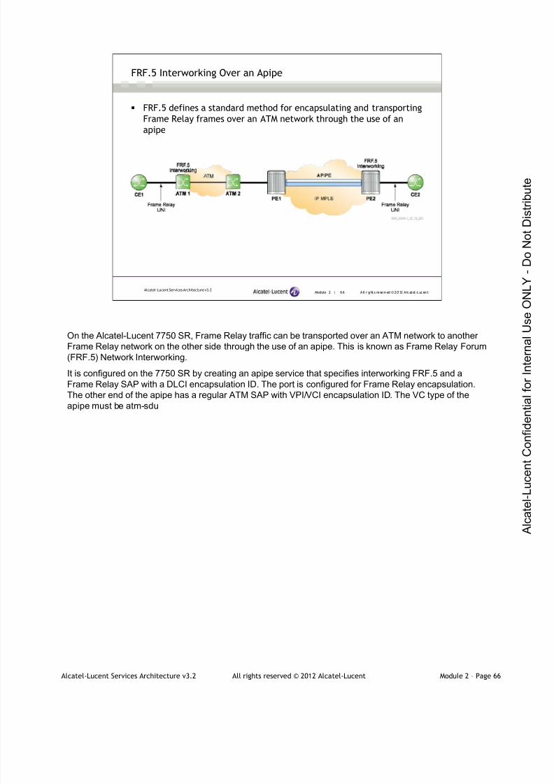
7/21/2019 Services Architecture v3.2 Student Guide Download
http://slidepdf.com/reader/full/services-architecture-v32-student-guide-download 167/429
Alcatel-Lucent Services Architecture v3.2 All rights reserved © 2012 Alcatel-Lucent Module 2 – Page 66
Module 2 | 66 A ll r ights re se rved ©2012 A lcatel -LucentAlcatel-Lucent Services Architecture v3.2
FRF.5 Interworking Over an Apipe
FRF.5 defines a standard method for encapsulating and transporting
Frame Relay frames over an ATM network through the use of an
apipe
On the Alcatel-Lucent 7750 SR, Frame Relay traffic can be transported over an ATM network to another
Frame Relay network on the other side through the use of an apipe. This is known as Frame Relay Forum
(FRF.5) Network Interworking.
It is configured on the 7750 SR by creating an apipe service that specifies interworking FRF.5 and a
Frame Relay SAP with a DLCI encapsulation ID. The port is configured for Frame Relay encapsulation.
The other end of the apipe has a regular ATM SAP with VPI/VCI encapsulation ID. The VC type of the
apipe must be atm-sdu

7/21/2019 Services Architecture v3.2 Student Guide Download
http://slidepdf.com/reader/full/services-architecture-v32-student-guide-download 168/429
Alcatel-Lucent Services Architecture v3.2 All rights reserved © 2012 Alcatel-Lucent Module 2 – Page 67
Module 2 | 67 A ll r ights re se rved ©2012 A lcatel -LucentAlcatel-Lucent Services Architecture v3.2
Ethernet Interworking VPWS
Epipe is used between the Ethernet user and the ATM-attached user or
Frame-Relay-attached user
Provides ATM and Frame Relay bridged encapsulation access to the epipeservice of an Alcatel-Lucent 7750 SR
This slide provides an example of an Ethernet interworking VPWS. The Ethernet interworking VPWS
provides a point-to-point Ethernet VPWS between Frame-Relay-attached users, ATM-attached users and
Ethernet-attached users across an IP/MPLS packet-switched network. It effectively provides ATM and
Frame Relay bridged encapsulation termination on the existing Epipe service of the 7750SR.
The Frame Relay network must be sending and receiving Ethernet encapsulated frames as defined by
RFC 2427 (Multiprotocol Interconnect over Frame Relay). The ATM network must be sending and
receiving Ethernet encapsulated frames as defined by RFC 2684 (Multiprotocol Encapsulation over
AAL5). One side of the epipe has either a Frame Relay or ATM SAP, the other an Ethernet SAP. Any
VLAN tags in the encapsulated frames are passed transparently as they would be for a null SAP.
7/21/2019 Services Architecture v3.2 Student Guide Download
http://slidepdf.com/reader/full/services-architecture-v32-student-guide-download 169/429
Alcatel-Lucent Services Architecture v3.2 All rights reserved © 2012 Alcatel-Lucent Module 2 – Page 68
Module 2 | 68 A ll r ights re se rved ©2012 A lcatel -LucentAlcatel-Lucent Services Architecture v3.2
IP Interworking VPWS (Ipipes)
Ipipe is a point-to-point Ethernet interworking VPWS that supports
interconnection between hosts that are attached to different point-
to-point access circuits on either end of a pseudowire
Ipipe provides a routed interworking service
Only IP traffic can be transported over an ipipe
Ipipe is useful for network migration purposes
Ipipe is a point-to-point Ethernet interworking VPWS that supports interconnection between hosts that are
attached to different point-to-point access circuits on either end of a pseudowire.
Ipipe supports interconnection between:
• ATM - using RFC 2684 routed encapsulation.
•Frame Relay - using RFC 2427 routed encapsulation.
•point-to-point protocol (PPP) - using IPCP encapsulation as defined in RFC 1332
•Ethernet - using null, dot1Q or Q-in-Q encapsulation
•Cisco HDLC - routed encapsulation
The difference between Ethernet interworking VPWS and an IP interworking VPWS (ipipe) is that the
former supports bridged encapsulation and the latter supports routed encapsulation. Ipipes provide a
routed interworking service. We say routed because the encapsulated data are Layer 3 (IP) packets
instead of the Layer 2 frames. They are not truly routed, since the ipipe is a point-to-point service.
Ipipe is useful for network migration purposes; for example, in the interim step during ATM/Frame Relay
network to Ethernet network migration, where ATM/Frame Relay equipment uses routed IP encapsulation.
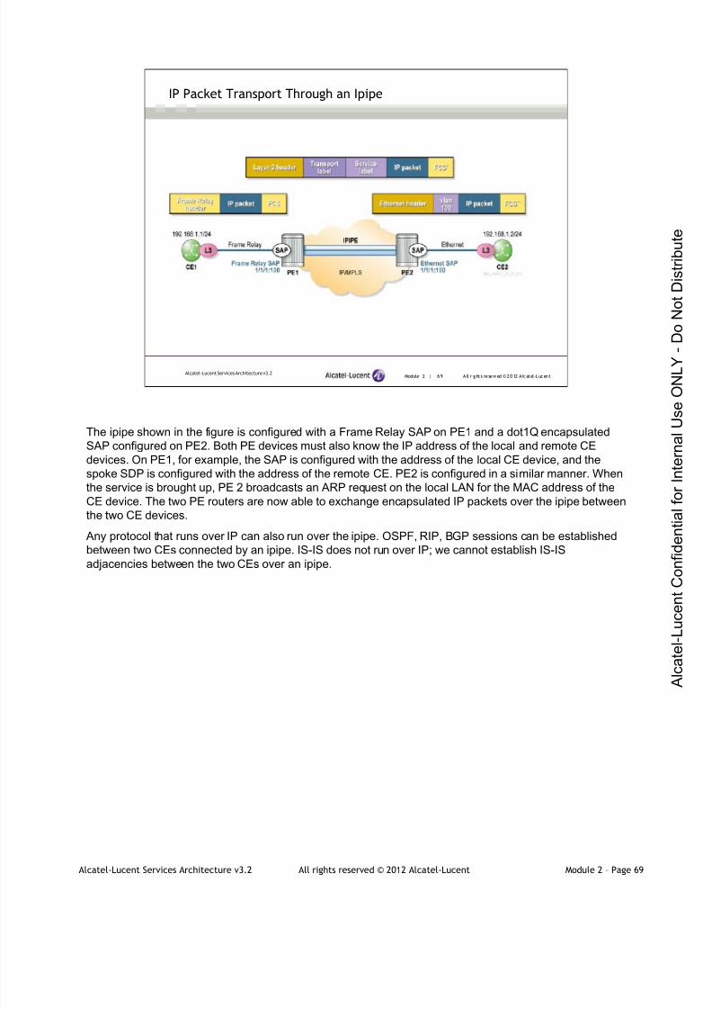
7/21/2019 Services Architecture v3.2 Student Guide Download
http://slidepdf.com/reader/full/services-architecture-v32-student-guide-download 170/429
Alcatel-Lucent Services Architecture v3.2 All rights reserved © 2012 Alcatel-Lucent Module 2 – Page 69
Module 2 | 69 A ll r ights re se rved ©2012 A lcatel -LucentAlcatel-Lucent Services Architecture v3.2
IP Packet Transport Through an Ipipe
The ipipe shown in the figure is configured with a Frame Relay SAP on PE1 and a dot1Q encapsulated
SAP configured on PE2. Both PE devices must also know the IP address of the local and remote CE
devices. On PE1, for example, the SAP is configured with the address of the local CE device, and the
spoke SDP is configured with the address of the remote CE. PE2 is configured in a similar manner. When
the service is brought up, PE 2 broadcasts an ARP request on the local LAN for the MAC address of the
CE device. The two PE routers are now able to exchange encapsulated IP packets over the ipipe between
the two CE devices.
Any protocol that runs over IP can also run over the ipipe. OSPF, RIP, BGP sessions can be established
between two CEs connected by an ipipe. IS-IS does not run over IP; we cannot establish IS-IS
adjacencies between the two CEs over an ipipe.
7/21/2019 Services Architecture v3.2 Student Guide Download
http://slidepdf.com/reader/full/services-architecture-v32-student-guide-download 171/429
Alcatel-Lucent Services Architecture v3.2 All rights reserved © 2012 Alcatel-Lucent Module 2 – Page 70
Module 2 | 70 A ll r ights re se rved ©2012 A lcatel -LucentAlcatel-Lucent Services Architecture v3.2
Module Summary
Alcatel-Lucent supports epipe, apipe, fpipe, cpipe and ipipe as
VPWS applications
Ethernet SAP encapsulation types are null, dot1q, and qinq
For null encapsulation, the service is delimited by the port
In dot1q encapsulation, the service is delimited by the VLAN tag
In qinq encapsulation, the service is delimited by two VLAN tags
Null SAP and default SAP are mutually exclusive on a port
On the 7750 SR, VLAN tags are stripped at the SAP ingress by default
7/21/2019 Services Architecture v3.2 Student Guide Download
http://slidepdf.com/reader/full/services-architecture-v32-student-guide-download 172/429
Alcatel-Lucent Services Architecture v3.2 All rights reserved © 2012 Alcatel-Lucent Module 2 – Page 71
Module 2 | 71 A ll r ights re se rved ©2012 A lcatel -LucentAlcatel-Lucent Services Architecture v3.2
Module Summary (continued)
Service MTU defines the maximum customer payload that can be carried in
a VPN service
SAP MTU is changed by changing the port MTU
The SDP path MTU defines the maximum payload size that can be carried by
a service using that SDP
Network port MTU >= SDP path-MTU + transport tunnel encapsulation
overhead
Fpipe provides a point-to-point Frame Relay service between users
connected to 7750SR nodes on the IP/MPLS network
Apipe provides a point-to-point ATM service between users connected to
7750 SR routers on an IP/MPLS network

7/21/2019 Services Architecture v3.2 Student Guide Download
http://slidepdf.com/reader/full/services-architecture-v32-student-guide-download 173/429
Alcatel-Lucent Services Architecture v3.2 All rights reserved © 2012 Alcatel-Lucent Module 2 – Page 72
Module 2 | 72 A ll r ights re se rved ©2012 A lcatel -LucentAlcatel-Lucent Services Architecture v3.2
Module Summary (continued)
Cpipes are an implementation of TDM pseudowires to transport T1 or E1
circuits
The Alcatel-Lucent VPWS offers network interworking for Ethernet, ATM andFrame Relay across a common IP/MPLS network
FRF.5 defines a standard method for encapsulating and transporting Frame
Relay frames over an ATM network
The Ethernet interworking VPWS provides a point-to-point Ethernet VPWS
between Frame-Relay-attached users, ATM-attached users and Ethernet-
attached users across an IP/MPLS packet-switched network
Ipipe provides a routed interworking service
7/21/2019 Services Architecture v3.2 Student Guide Download
http://slidepdf.com/reader/full/services-architecture-v32-student-guide-download 174/429
Alcatel-Lucent Services Architecture v3.2 All rights reserved © 2012 Alcatel-Lucent Module 2 – Page 73
Module 2 | 73 A ll r ights re se rved ©2012 A lcatel -LucentAlcatel-Lucent Services Architecture v3.2
Learning Assessment
1. Which VPWS emulates a point-to-point TDM circuit?
2. What is the purpose of using a VLAN tag?
3. Verify whether the following statement is true or false: MultipleSAPs can be defined on a single port for different services
4. What frames will a dot1q null sap receive?
5. What is the default service MTU value for an Ethernet VPN service
such as an epipe?
6. What is the relationship between the network port MTU and the SDP
path MTU?
7. What are the two modes of operation supported on Alcatel-Lucent
7750 SR for an apipe service?
1. Which VPWS emulates a point-to-point TDM circuit?
Cpipe service emulates a point-to-point TDM circuit
2. What is the purpose of using VLAN tag?
VLAN tag is used to determine to which service the frame belongs
3. Verify whether the following statement is true or false: Multiple SAPs can be defined on a single port for
different services.
True
4. What frames will a dot1q null sap receive?
A dot 1q null sap receives all untagged frames and all frames with a VLAN tag of 0
5. What is the default service MTU value for an Ethernet VPN service such as an epipe?
An Ethernet VPN service, such as an epipe service, has a default service MTU of 1514 bytes
6. What is the relationship between the network port MTU and the SDP path MTU?
Network port MTU >= SDP path MTU + transport tunnel encapsulation overhead
7. What are the two modes of operation supported on Alcatel-Lucent 7750 SR for an apipe service?
The two modes of operation supported on the Alcatel-Lucent 7750 SR for ATM apipes are the N:1 cell
mode and AAL5 frame mode.
7/21/2019 Services Architecture v3.2 Student Guide Download
http://slidepdf.com/reader/full/services-architecture-v32-student-guide-download 175/429
Module 2 | 74 A ll r ights re se rved ©2012 A lcatel -LucentAlcatel-Lucent Services Architecture v3.2
www.alcatel-lucent.com/src
3FL-30636-AAAA-ZZZZA Edition 01

7/21/2019 Services Architecture v3.2 Student Guide Download
http://slidepdf.com/reader/full/services-architecture-v32-student-guide-download 176/429
Alcatel-Lucent Services Architecture v3.2 All rights reserved © 2012 Alcatel-Lucent Module 3 – Page 1
Alcatel-Lucent Services Architecture
Module 3 — Introduction to Virtual Private LAN Service (VPLS)
7/21/2019 Services Architecture v3.2 Student Guide Download
http://slidepdf.com/reader/full/services-architecture-v32-student-guide-download 177/429
Alcatel-Lucent Services Architecture v3.2 All rights reserved © 2012 Alcatel-Lucent Module 3 – Page 2
Module 3 | 2 A ll r ights re se rved ©2012 Alcate l-LucentAlcatel-Lucent Services Architecture v3.2
Module Objectives
After successfully completing this module, you will be able to:
Explain the operation of Virtual Private LAN Service (VPLS)
Explain how VPLS emulates a virtual Ethernet switch through
its MAC learning and flooding behavior
Configure and verify a VPLS
Compare VPLS topologies (full mesh, hub and spoke,
hierarchical VPLS, and spoke termination in a VPLS)

7/21/2019 Services Architecture v3.2 Student Guide Download
http://slidepdf.com/reader/full/services-architecture-v32-student-guide-download 178/429
Alcatel-Lucent Services Architecture v3.2 All rights reserved © 2012 Alcatel-Lucent Module 3 – Page 3
Module 3 — Introduction to VPLS
Section 1 — VPLS Operation
7/21/2019 Services Architecture v3.2 Student Guide Download
http://slidepdf.com/reader/full/services-architecture-v32-student-guide-download 179/429
Alcatel-Lucent Services Architecture v3.2 All rights reserved © 2012 Alcatel-Lucent Module 3 – Page 4
Module 3 | 4 A ll r ights re se rved ©2012 Alcate l-LucentAlcatel-Lucent Services Architecture v3.2
Section Objectives
After successfully completing this section, you will be able to:
Define a VPLS and list its features
Explain the similarities and differences between epipe and VPLS
List the advantages of a VPLS from the perspective of both the
customer and service provider
Explain VPLS flooding behavior
Identify the difference between mesh SDP and spoke SDP
Describe the MAC learning process in VPLS
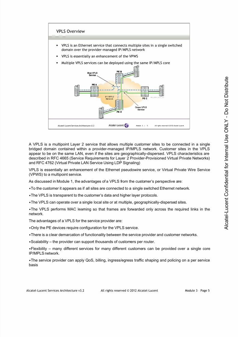
7/21/2019 Services Architecture v3.2 Student Guide Download
http://slidepdf.com/reader/full/services-architecture-v32-student-guide-download 180/429
Alcatel-Lucent Services Architecture v3.2 All rights reserved © 2012 Alcatel-Lucent Module 3 – Page 5
Module 3 | 5 A ll r ights re se rved ©2012 Alcate l-LucentAlcatel-Lucent Services Architecture v3.2
VPLS Overview
VPLS is an Ethernet service that connects multiple sites in a single switched
domain over the provider-managed IP/MPLS network
VPLS is essentially an enhancement of the VPWS
Multiple VPLS services can be deployed using the same IP/MPLS core
A VPLS is a multipoint Layer 2 service that allows multiple customer sites to be connected in a single
bridged domain contained within a provider-managed IP/MPLS network. Customer sites in the VPLS
appear to be on the same LAN, even if the sites are geographically-dispersed. VPLS characteristics are
described in RFC 4665 (Service Requirements for Layer 2 Provider-Provisioned Virtual Private Networks)
and RFC 4762 (Virtual Private LAN Service Using LDP Signaling)
VPLS is essentially an enhancement of the Ethernet pseudowire service, or Virtual Private Wire Service
(VPWS) to a multipoint service.
As discussed in Module 1, the advantages of a VPLS from the customer’s perspective are:
•To the customer it appears as if all sites are connected to a single switched Ethernet network.
•The VPLS is transparent to the customer’s data and higher layer protocols.
•The VPLS can operate over a single local site or at multiple, geographically-dispersed sites.
•The VPLS performs MAC learning so that frames are forwarded only across the required links in the
network.
The advantages of a VPLS for the service provider are:
•Only the PE devices require configuration for the VPLS service.
•There is a clear demarcation of functionality between the service provider and customer networks.•Scalability – the provider can support thousands of customers per router.
•Flexibility – many different services for many different customers can be provided over a single core
IP/MPLS network.
•The service provider can apply QoS, billing, ingress/egress traffic shaping and policing on a per service
basis

7/21/2019 Services Architecture v3.2 Student Guide Download
http://slidepdf.com/reader/full/services-architecture-v32-student-guide-download 181/429
Alcatel-Lucent Services Architecture v3.2 All rights reserved © 2012 Alcatel-Lucent Module 3 – Page 6
Module 3 | 6 A ll r ights re se rved ©2012 Alcate l-LucentAlcatel-Lucent Services Architecture v3.2
VPLS vs. Epipe
Similarities:
Encapsulation and transport mechanism
The signaling of transport and service labels
The SAP encapsulation types: null, dot1Q and Q-in-Q
The treatment of customer data at the SAP
Differences:
A VPLS is a multipoint service; epipe is a point-to-point service
The VPLS appears as a single switched LAN to the customer; the epipe appears as a
direct Ethernet connection
A VPLS performs MAC learning to build a forwarding database (FDB) containing the
addresses of customer-attached devices
The similarities between an epipe and a VPLS are
•They both use the same encapsulation and transport mechanism: an MPLS or GRE encapsulated packet
with an inner service label.
•The signaling of transport and service labels is the same: LDP or RSVP-TE for transport labels and T-
LDP for service labels.
•The SAP encapsulation types of null, dot1Q and Q-in-Q are the same for a VPLS as for an epipe.
•The treatment of customer data at the SAP is the same in a VPLS as in an epipe
The differences between an epipe and a VPLS service are:
• A VPLS is a multipoint service instead of the point-to-point service of an epipe.
•The VPLS appears as a single switched LAN to the customer, whereas the epipe appears as a direct
Ethernet connection.
• A VPLS performs MAC (Media Access Control) learning to build a forwarding database (FDB) containing
the addresses of customer-attached devices. The VPLS uses the FDB for intelligent forwarding of
customer traffic over the IP/MPLS core network.
Like other pseudowire services, a VPLS can be local (multiple sites connected to a single PE) or
distributed (multiple sites connected to multiple PEs).

7/21/2019 Services Architecture v3.2 Student Guide Download
http://slidepdf.com/reader/full/services-architecture-v32-student-guide-download 182/429
Alcatel-Lucent Services Architecture v3.2 All rights reserved © 2012 Alcatel-Lucent Module 3 – Page 7
Module 3 | 7 A ll r ights re se rved ©2012 Alcate l-LucentAlcatel-Lucent Services Architecture v3.2
VPLS: Customer Operation
Customers maintain complete control over routing
Adding new sites requires minimal reconfiguration at existing sites
VPLS 1 and VPLS 2 can use the same IP address ranges due to a VPN functionality provided with the
VPLS service.
Note: since VPLS is a Layer 2 service, the customer site router interfaces that connect to the VPLS must
belong to the same subnet. From the customer’s perspective, the routers are logically connected by a
Layer 2 Ethernet switch.
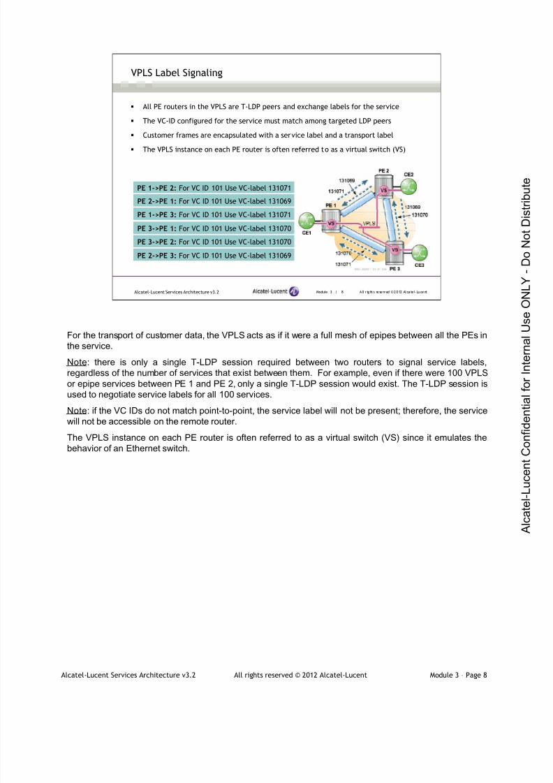
7/21/2019 Services Architecture v3.2 Student Guide Download
http://slidepdf.com/reader/full/services-architecture-v32-student-guide-download 183/429
Alcatel-Lucent Services Architecture v3.2 All rights reserved © 2012 Alcatel-Lucent Module 3 – Page 8
Module 3 | 8 A ll r ights re se rved ©2012 Alcate l-LucentAlcatel-Lucent Services Architecture v3.2
VPLS Label Signaling
All PE routers in the VPLS are T-LDP peers and exchange labels for the service
The VC-ID configured for the service must match among targeted LDP peers
Customer frames are encapsulated with a service label and a transport label
The VPLS instance on each PE router is often referred to as a virtual switch (VS)
PE 1->PE 2: For VC ID 101 Use VC-label 131071
PE 2->PE 1: For VC ID 101 Use VC-label 131069
PE 1->PE 3: For VC ID 101 Use VC-label 131071
PE 2->PE 3: For VC ID 101 Use VC-label 131069
PE 3->PE 1: For VC ID 101 Use VC-label 131070
PE 3->PE 2: For VC ID 101 Use VC-label 131070
For the transport of customer data, the VPLS acts as if it were a full mesh of epipes between all the PEs in
the service.
Note: there is only a single T-LDP session required between two routers to signal service labels,
regardless of the number of services that exist between them. For example, even if there were 100 VPLS
or epipe services between PE 1 and PE 2, only a single T-LDP session would exist. The T-LDP session is
used to negotiate service labels for all 100 services.
Note: if the VC IDs do not match point-to-point, the service label will not be present; therefore, the servicewill not be accessible on the remote router.
The VPLS instance on each PE router is often referred to as a virtual switch (VS) since it emulates the
behavior of an Ethernet switch.
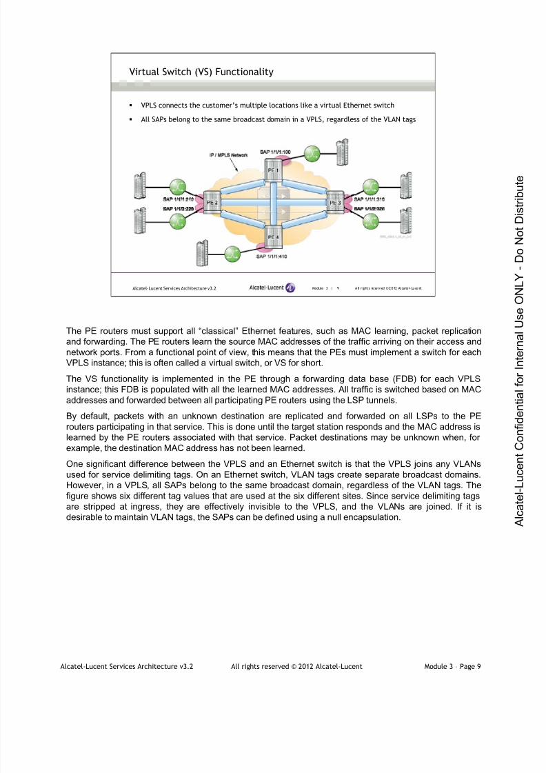
7/21/2019 Services Architecture v3.2 Student Guide Download
http://slidepdf.com/reader/full/services-architecture-v32-student-guide-download 184/429
Alcatel-Lucent Services Architecture v3.2 All rights reserved © 2012 Alcatel-Lucent Module 3 – Page 9
Module 3 | 9 A ll r ights re se rved ©2012 Alcate l-LucentAlcatel-Lucent Services Architecture v3.2
Virtual Switch (VS) Functionality
VPLS connects the customer’s multiple locations like a virtual Ethernet switch
All SAPs belong to the same broadcast domain in a VPLS, regardless of the VLAN tags
The PE routers must support all “classical” Ethernet features, such as MAC learning, packet replication
and forwarding. The PE routers learn the source MAC addresses of the traffic arriving on their access and
network ports. From a functional point of view, this means that the PEs must implement a switch for each
VPLS instance; this is often called a virtual switch, or VS for short.
The VS functionality is implemented in the PE through a forwarding data base (FDB) for each VPLS
instance; this FDB is populated with all the learned MAC addresses. All traffic is switched based on MAC
addresses and forwarded between all participating PE routers using the LSP tunnels.
By default, packets with an unknown destination are replicated and forwarded on all LSPs to the PE
routers participating in that service. This is done until the target station responds and the MAC address is
learned by the PE routers associated with that service. Packet destinations may be unknown when, for
example, the destination MAC address has not been learned.
One significant difference between the VPLS and an Ethernet switch is that the VPLS joins any VLANs
used for service delimiting tags. On an Ethernet switch, VLAN tags create separate broadcast domains.
However, in a VPLS, all SAPs belong to the same broadcast domain, regardless of the VLAN tags. The
figure shows six different tag values that are used at the six different sites. Since service delimiting tags
are stripped at ingress, they are effectively invisible to the VPLS, and the VLANs are joined. If it is
desirable to maintain VLAN tags, the SAPs can be defined using a null encapsulation.
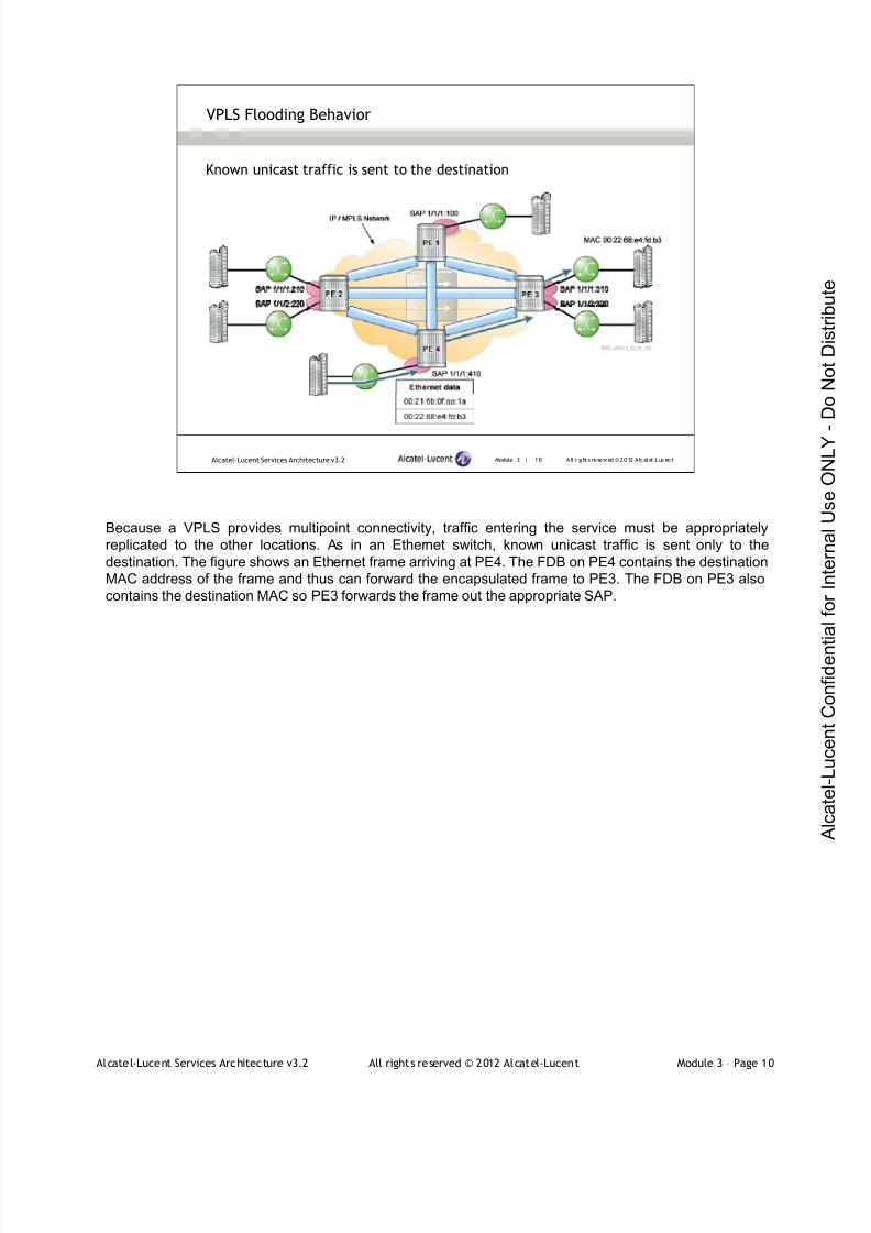
7/21/2019 Services Architecture v3.2 Student Guide Download
http://slidepdf.com/reader/full/services-architecture-v32-student-guide-download 185/429
Alcatel-Lucent Services Architecture v3.2 All rights reserved © 2012 Alcatel-Lucent Module 3 – Page 10
Module 3 | 10 A ll r ights re se rved ©2012 A lcatel -LucentAlcatel-Lucent Services Architecture v3.2
VPLS Flooding Behavior
Known unicast traffic is sent to the destination
Because a VPLS provides multipoint connectivity, traffic entering the service must be appropriately
replicated to the other locations. As in an Ethernet switch, known unicast traffic is sent only to the
destination. The figure shows an Ethernet frame arriving at PE4. The FDB on PE4 contains the destination
MAC address of the frame and thus can forward the encapsulated frame to PE3. The FDB on PE3 also
contains the destination MAC so PE3 forwards the frame out the appropriate SAP.

7/21/2019 Services Architecture v3.2 Student Guide Download
http://slidepdf.com/reader/full/services-architecture-v32-student-guide-download 186/429
Alcatel-Lucent Services Architecture v3.2 All rights reserved © 2012 Alcatel-Lucent Module 3 – Page 11
Module 3 | 11 A ll r ights re se rved ©2012 A lcatel -LucentAlcatel-Lucent Services Architecture v3.2
VPLS Flooding Behavior (continued)
Traffic to multicast, broadcast or unknown unicast addresses is flooded to all local
SAPs and remote PEs in the service
In a basic VPLS, the SDP is bound to the service as a mesh SDP
Mesh SDP floods frames received from a SAP or from a spoke SDP, but does not floodframes received from another mesh SDP
Mesh SDPs prevent loops
On an Ethernet switch, traffic to multicast, broadcast or unknown unicast addresses is flooded to all ports.
A VPLS also floods such traffic to all SAPs in the service.
When an SDP is bound to a service, it is bound as either a spoke SDP or a mesh SDP. The type of SDP
indicates how flooded traffic is transmitted.
All mesh SDPs bound to a service are logically treated as a single bridge “port” for flooded traffic; flooded
traffic received on any mesh SDP on the service is replicated to other “ports” (spoke SDPs and SAPs) and
is not transmitted on any mesh SDPs.
In the figure, PE3 forwards the frame it receives only to the SAPs and not on the SDP to PE1 or PE2. In a
basic VPLS such as this one, the SDP is bound to the service as a mesh SDP. In a VPWS, the SDP is
bound as a spoke SDP. The only difference between the two is their flooding behavior.
A basic VPLS is configured with a full mesh of mesh SDPs between all the PE routers in the service.
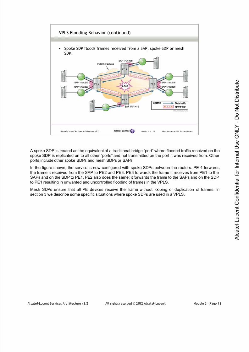
7/21/2019 Services Architecture v3.2 Student Guide Download
http://slidepdf.com/reader/full/services-architecture-v32-student-guide-download 187/429
Alcatel-Lucent Services Architecture v3.2 All rights reserved © 2012 Alcatel-Lucent Module 3 – Page 12
Module 3 | 12 A ll r ights re se rved ©2012 A lcatel -LucentAlcatel-Lucent Services Architecture v3.2
VPLS Flooding Behavior (continued)
Spoke SDP floods frames received from a SAP, spoke SDP or mesh
SDP
A spoke SDP is treated as the equivalent of a traditional bridge “port” where flooded traffic received on the
spoke SDP is replicated on to all other “ports” and not transmitted on the port it was received from. Other
ports include other spoke SDPs and mesh SDPs or SAPs.
In the figure shown, the service is now configured with spoke SDPs between the routers. PE 4 forwards
the frame it received from the SAP to PE2 and PE3. PE3 forwards the frame it receives from PE1 to the
SAPs and on the SDP to PE1. PE2 also does the same; it forwards the frame to the SAPs and on the SDP
to PE1 resulting in unwanted and uncontrolled flooding of frames in the VPLS.
Mesh SDPs ensure that all PE devices receive the frame without looping or duplication of frames. In
section 3 we describe some specific situations where spoke SDPs are used in a VPLS.
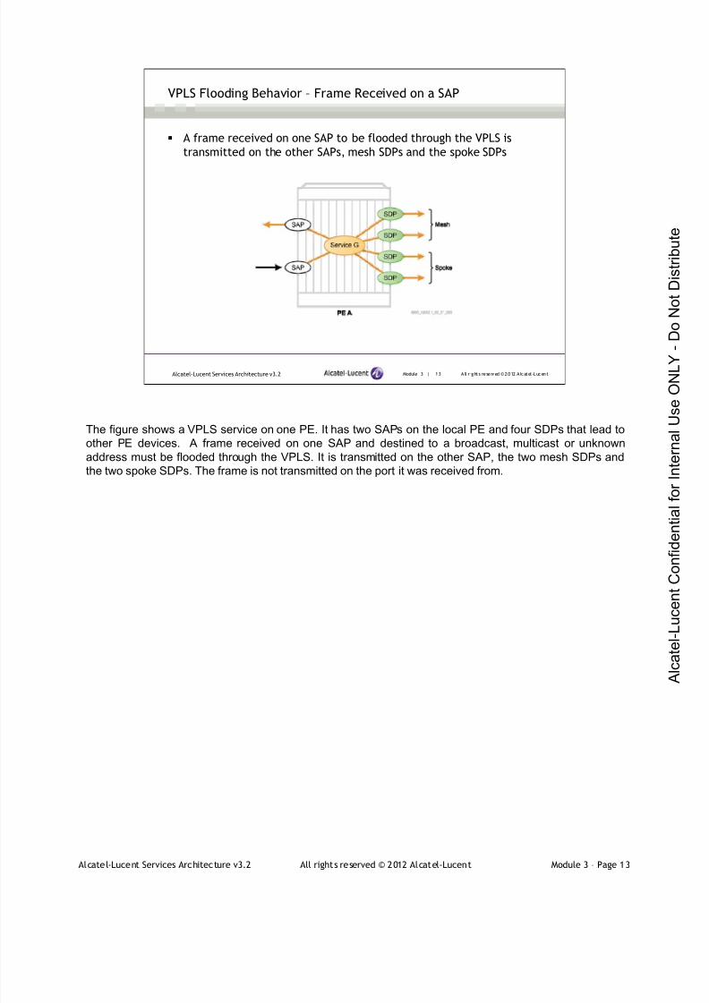
7/21/2019 Services Architecture v3.2 Student Guide Download
http://slidepdf.com/reader/full/services-architecture-v32-student-guide-download 188/429
Alcatel-Lucent Services Architecture v3.2 All rights reserved © 2012 Alcatel-Lucent Module 3 – Page 13
Module 3 | 13 A ll r ights re se rved ©2012 A lcatel -LucentAlcatel-Lucent Services Architecture v3.2
VPLS Flooding Behavior – Frame Received on a SAP
A frame received on one SAP to be flooded through the VPLS is
transmitted on the other SAPs, mesh SDPs and the spoke SDPs
The figure shows a VPLS service on one PE. It has two SAPs on the local PE and four SDPs that lead to
other PE devices. A frame received on one SAP and destined to a broadcast, multicast or unknown
address must be flooded through the VPLS. It is transmitted on the other SAP, the two mesh SDPs and
the two spoke SDPs. The frame is not transmitted on the port it was received from.
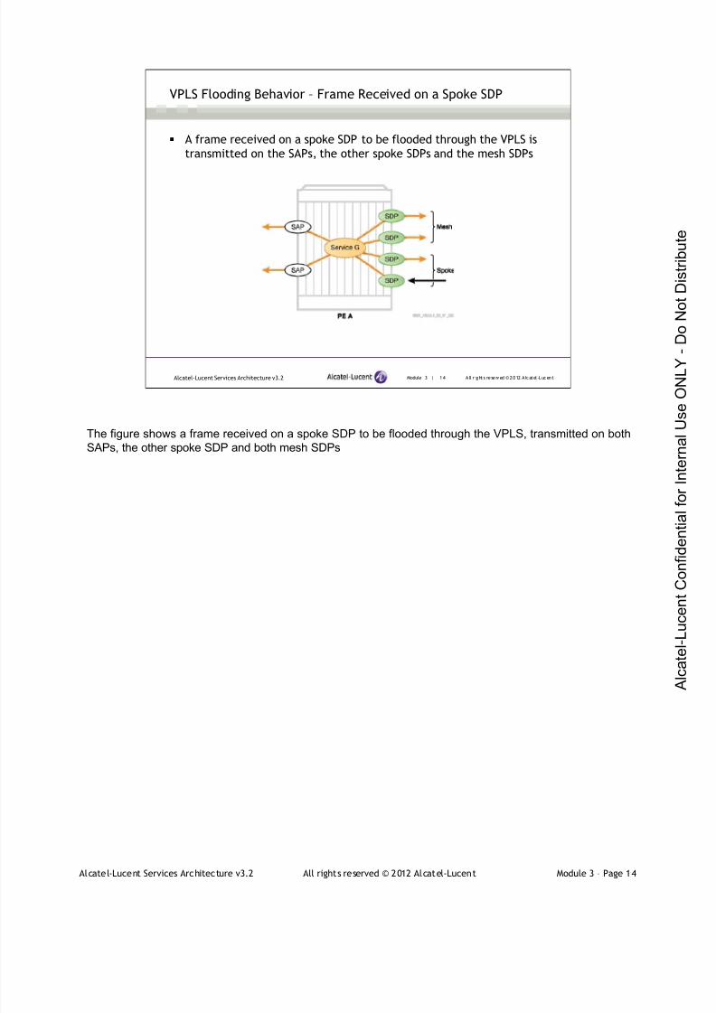
7/21/2019 Services Architecture v3.2 Student Guide Download
http://slidepdf.com/reader/full/services-architecture-v32-student-guide-download 189/429
Alcatel-Lucent Services Architecture v3.2 All rights reserved © 2012 Alcatel-Lucent Module 3 – Page 14
Module 3 | 14 A ll r ights re se rved ©2012 A lcatel -LucentAlcatel-Lucent Services Architecture v3.2
VPLS Flooding Behavior – Frame Received on a Spoke SDP
A frame received on a spoke SDP to be flooded through the VPLS is
transmitted on the SAPs, the other spoke SDPs and the mesh SDPs
The figure shows a frame received on a spoke SDP to be flooded through the VPLS, transmitted on both
SAPs, the other spoke SDP and both mesh SDPs

7/21/2019 Services Architecture v3.2 Student Guide Download
http://slidepdf.com/reader/full/services-architecture-v32-student-guide-download 190/429
Alcatel-Lucent Services Architecture v3.2 All rights reserved © 2012 Alcatel-Lucent Module 3 – Page 15
Module 3 | 15 A ll r ights re se rved ©2012 A lcatel -LucentAlcatel-Lucent Services Architecture v3.2
VPLS Flooding Behavior – Frame Received on a Mesh SDP
A frame received on a mesh SDP to be flooded through the VPLS is
transmitted on the SAPs and the other spoke SDPs, but not the other
mesh SDPs
The figure shows a frame received on a mesh SDP to be flooded through the VPLS, transmitted on both
SAPs, both spoke SDPs, but not the other mesh SDP

7/21/2019 Services Architecture v3.2 Student Guide Download
http://slidepdf.com/reader/full/services-architecture-v32-student-guide-download 191/429
Alcatel-Lucent Services Architecture v3.2 All rights reserved © 2012 Alcatel-Lucent Module 3 – Page 16
Module 3 | 16 A ll r ights re se rved ©2012 A lcatel -LucentAlcatel-Lucent Services Architecture v3.2
MAC Learning in a VPLS
The learned MAC addresses are stored in a forwarding database
(FDB) kept on each PE device
The VPLS learns the MAC addresses of the customer’s attached devices in the same manner as an
Ethernet switch. The learned addresses are stored in a forwarding database (FDB) kept on each PE
device.
The PE maintains a separate FDB for every VPLS service configured on the router. The figure shows the
two FDBs maintained on PE1 for two different VPLS services.
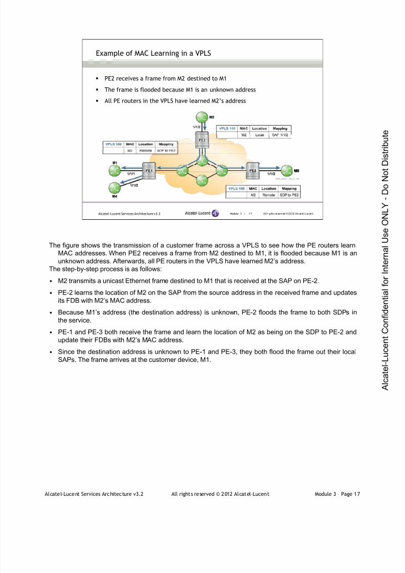
7/21/2019 Services Architecture v3.2 Student Guide Download
http://slidepdf.com/reader/full/services-architecture-v32-student-guide-download 192/429
Alcatel-Lucent Services Architecture v3.2 All rights reserved © 2012 Alcatel-Lucent Module 3 – Page 17
Module 3 | 17 A ll r ights re se rved ©2012 A lcatel -LucentAlcatel-Lucent Services Architecture v3.2
Example of MAC Learning in a VPLS
PE2 receives a frame from M2 destined to M1
The frame is flooded because M1 is an unknown address
All PE routers in the VPLS have learned M2’s address
The figure shows the transmission of a customer frame across a VPLS to see how the PE routers learn
MAC addresses. When PE2 receives a frame from M2 destined to M1, it is flooded because M1 is an
unknown address. Afterwards, all PE routers in the VPLS have learned M2’s address.
The step-by-step process is as follows:
• M2 transmits a unicast Ethernet frame destined to M1 that is received at the SAP on PE-2.
• PE-2 learns the location of M2 on the SAP from the source address in the received frame and updates
its FDB with M2’s MAC address.
• Because M1’s address (the destination address) is unknown, PE-2 floods the frame to both SDPs in
the service.
• PE-1 and PE-3 both receive the frame and learn the location of M2 as being on the SDP to PE-2 and
update their FDBs with M2’s MAC address.
• Since the destination address is unknown to PE-1 and PE-3, they both flood the frame out their local
SAPs. The frame arrives at the customer device, M1.

7/21/2019 Services Architecture v3.2 Student Guide Download
http://slidepdf.com/reader/full/services-architecture-v32-student-guide-download 193/429
Alcatel-Lucent Services Architecture v3.2 All rights reserved © 2012 Alcatel-Lucent Module 3 – Page 18
Module 3 | 18 A ll r ights re se rved ©2012 A lcatel -LucentAlcatel-Lucent Services Architecture v3.2
Example of MAC Learning in a VPLS (continued)
M1 sends a frame to M2, the frame is sent directly to PE2
Once the frame arrives at M2, both PE1 and PE2 have learned M1’s MAC address and
have it in their FDBs
PE3 does not learn the MAC address of M1
M1 next sends a frame to M2. Since M2 is now known in the FDB, the frame does not have to be flooded
and can be sent directly to PE2. Once the frame arrives at M2, both PE1 and PE-2 have learned M1’s
MAC address and have it in their FDBs
The step-by-step process is as follows:
• M1 transmits a frame with M2 as the destination. The frame arrives at the SAP on PE1.
• PE1 has the MAC address for M2 in its FDB and knows to transmit the frame on the SDP to PE2. PE1
learns the location of M1 from the source address in the frame and updates its FDB.
• PE2 has the MAC address for M2 in its FDB and knows to transmit the frame out the SAP. PE2 learns
the location of M1 from the source address in the frame and updates its FDB. The frame arrives at the
destination, M2.
After the transmission from M1 to M2, both PE1 and PE2 have an entry for M1 in their FDB. Since the
frame from M1 was not flooded in the VPLS, PE3 does not have M1 in its FDB. If it receives a frame
destined for M1 it will be flooded in the VPLS by PE3.
Note: if M2 is to send a frame to M1, the flow of the frame will be from M2 to PE2, PE2 to PE1, and PE1
will only send it over SAP 1/1/1 to M1. The frame will not be sent over SAP 1/1/2 as in the previous
slide.

7/21/2019 Services Architecture v3.2 Student Guide Download
http://slidepdf.com/reader/full/services-architecture-v32-student-guide-download 194/429
Alcatel-Lucent Services Architecture v3.2 All rights reserved © 2012 Alcatel-Lucent Module 3 – Page 19
Module 3 — Introduction to VPLS
Section 2 — VPLS Configuration and Verification

7/21/2019 Services Architecture v3.2 Student Guide Download
http://slidepdf.com/reader/full/services-architecture-v32-student-guide-download 195/429
Alcatel-Lucent Services Architecture v3.2 All rights reserved © 2012 Alcatel-Lucent Module 3 – Page 20
Module 3 | 20 A ll r ights re se rved ©2012 A lcatel -LucentAlcatel-Lucent Services Architecture v3.2
Section Objectives
After successfully completing this section, you will be able to:
Identify the steps to configure a VPLS
Configure and verify a VPLS
Complete Lab 3 — Configuring a VPLS
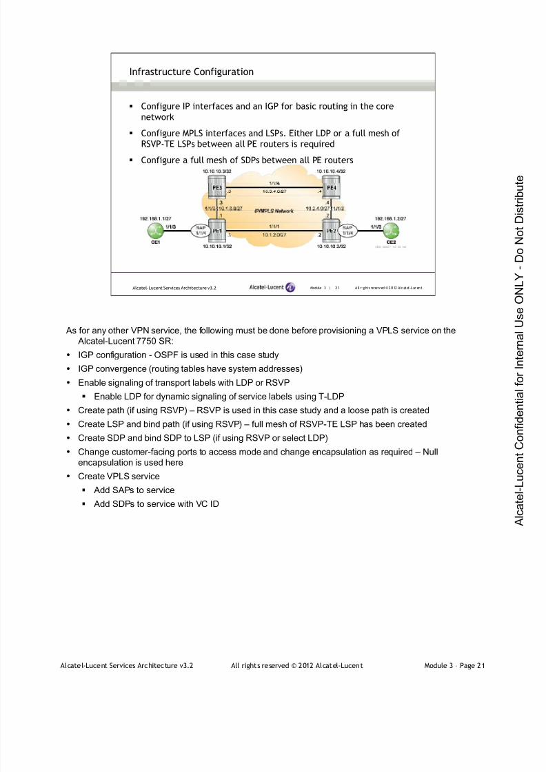
7/21/2019 Services Architecture v3.2 Student Guide Download
http://slidepdf.com/reader/full/services-architecture-v32-student-guide-download 196/429
Alcatel-Lucent Services Architecture v3.2 All rights reserved © 2012 Alcatel-Lucent Module 3 – Page 21
Module 3 | 21 A ll r ights re se rved ©2012 A lcatel -LucentAlcatel-Lucent Services Architecture v3.2
Infrastructure Configuration
Configure IP interfaces and an IGP for basic routing in the core
network
Configure MPLS interfaces and LSPs. Either LDP or a full mesh ofRSVP-TE LSPs between all PE routers is required
Configure a full mesh of SDPs between all PE routers
As for any other VPN service, the following must be done before provisioning a VPLS service on the
Alcatel-Lucent 7750 SR:
IGP configuration - OSPF is used in this case study
IGP convergence (routing tables have system addresses)
Enable signaling of transport labels with LDP or RSVP
Enable LDP for dynamic signaling of service labels using T-LDP
Create path (if using RSVP) – RSVP is used in this case study and a loose path is created
Create LSP and bind path (if using RSVP) – full mesh of RSVP-TE LSP has been created
Create SDP and bind SDP to LSP (if using RSVP or select LDP)
Change customer-facing ports to access mode and change encapsulation as required – Null
encapsulation is used here
Create VPLS service
Add SAPs to service
Add SDPs to service with VC ID

7/21/2019 Services Architecture v3.2 Student Guide Download
http://slidepdf.com/reader/full/services-architecture-v32-student-guide-download 197/429
Alcatel-Lucent Services Architecture v3.2 All rights reserved © 2012 Alcatel-Lucent Module 3 – Page 22
Module 3 | 22 A ll r ights re se rved ©2012 A lcatel -LucentAlcatel-Lucent Services Architecture v3.2
IP Interfaces and an IGP Configuration / Verification
*A:PE-1>conf i g>router>ospf # i nfo- - - - - - - - - - - - - - - - - - - - - - - - - - - - - - - - - - - - - - - - - - - - - -
traff i c -engi neeri ngarea 0. 0.0.0
i nterf ace "syst em"exi ti nterface "to- PE2"
i nterface-t ype poi nt-t o-poi ntexi ti nterface "to- PE3"
i nterface-t ype poi nt-t o-poi ntexi t
exi t- - - - - - - - - - - - - - - - - - - - - - - - - - - - - - - - - - - - - - - - - - - - - -
*A:PE-1#showr outer route-t abl e===============================================================================Route Tabl e (Router : Base)===============================================================================Dest Pref i x Type Prot o Age Pr ef
Next Hop[I nterf ace Name] Metr i c- - - - - - - - - - - - - - - - - - - - - - -- - - - - - - - - - - - - - - - - - - - - - - - -- - - - - - - - - - - - - - - - - - - - - - - -- - - - - - -10.1.2.0/ 27 Local Local 04d23h51m 0
to- PE2 010.1.3.0/ 27 Local Local 04d23h51m 0
to- PE3 010.2. 4.0/ 27 Remote OSPF 04d23h36m 10
10. 1.2.2 20010.3. 4.0/ 27 Remote OSPF 04d23h35m 10
10. 1.3.3 20010.10.10.1/32 Local Local 22d18h14m 0
system 010.10.10. 2/32 Remote OSPF 04d23h36m 10
10. 1.2.2 10010.10.10. 3/32 Remote OSPF 04d23h36m 10
10. 1.3.3 10010.10.10. 4/32 Remote OSPF 04d23h36m 10
10. 1.2.2 200- - - - - - - - - - - - - - - - - - - - - - -- - - - - - - - - - - - - - - - - - - - - - - - -- - - - - - - - - - - - - - - - - - - - - - - -- - - - - - -No. of Routes: 8
A single area OSPF with traffic engineering enabled is configured on the PE routers.
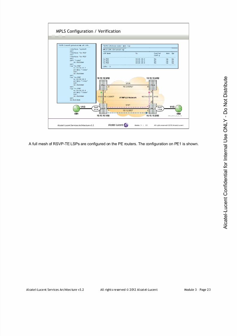
7/21/2019 Services Architecture v3.2 Student Guide Download
http://slidepdf.com/reader/full/services-architecture-v32-student-guide-download 198/429
Alcatel-Lucent Services Architecture v3.2 All rights reserved © 2012 Alcatel-Lucent Module 3 – Page 23
Module 3 | 23 A ll r ights re se rved ©2012 A lcatel -LucentAlcatel-Lucent Services Architecture v3.2
MPLS Configuration / Verification
*A:PE-1#showr outer mpls l sp===============================================================================MPLS LSPs (Ori ginati ng)===============================================================================L SP Name To F as t f ai l Adm Opr
Confi g- - - - - - - - - - - - - - - - - - - - - - - -- - - - - - - - - - - - - - - - - - - - - - - - -- - - - - - - - - - - - - - - - - - - - - - - -- - - - - -
t o- PE2 10.10. 10. 2 No Up Upt o- PE3 10.10. 10. 3 No Up Upt o- PE4 10.10. 10. 4 No Up Up- - - - - - - - - - - - - - - - - - - - - - - -- - - - - - - - - - - - - - - - - - - - - - - - -- - - - - - - - - - - - - - - - - - - - - - - -- - - - - -L SP s : 3
*A:PE- 1>confi g>rout er>mpl s# i nfo- - - - - - - - - - - - - - - - - - - - - - - - - - - - - - - - - -
i nterface "system"exi ti nterface "to- PE2"exi ti nterface "to- PE3"
exi tpath "l oose"
no shut downexi tl sp " to-PE2"
to 10.10.10. 2pri mary "l oose"exi tno shut down
exi tl sp " to-PE3"
to 10.10.10. 3pri mary "l oose"exi tno shut down
exi tl sp " to-PE4"
to 10.10.10. 4pri mary "l oose"exi tno shut down
exi tno shut down
- - - - - - - - - - - - - - - - - - - - - - - - - - - - - - -
A full mesh of RSVP-TE LSPs are configured on the PE routers. The configuration on PE1 is shown.
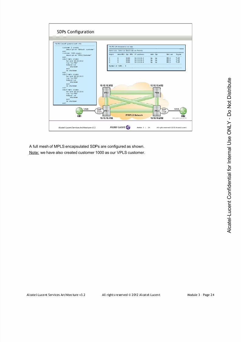
7/21/2019 Services Architecture v3.2 Student Guide Download
http://slidepdf.com/reader/full/services-architecture-v32-student-guide-download 199/429
Alcatel-Lucent Services Architecture v3.2 All rights reserved © 2012 Alcatel-Lucent Module 3 – Page 24
Module 3 | 24 A ll r ights re se rved ©2012 A lcatel -LucentAlcatel-Lucent Services Architecture v3.2
SDPs Configuration
*A:PE-1>confi g>servi ce#i nfo- - - - - - - - - - - - - - - - - - - - - - - - - - - - - - - - - - - - - - - - - -
customer 1 createdescri pti on "Default customer"
exi tcustomer 1000 creat e
descri pti on "VPLS_Customer"exi t
sdp 2 mpls createfar -end 10.10.10.2l sp " to-PE2"keep-al i ve
shut downexi tno shut down
exi tsdp 3 mpls create
far -end 10.10.10.3l sp " to-PE3"keep-al i ve
shut downexi tno shut down
exi tsdp 4 mpls create
far -end 10.10.10.4l sp " to-PE4"keep-al i ve
shut downexi tno shut down
exi t
*A:PE-1# showservi ce sdp==============================================================================Servi ces: Servi ce Desti nati on Points==============================================================================SdpI d Adm MTU Opr MTU I P addr es s Adm Opr Del i ver Si g nal- - - - - - - - - - - - - - - - - - - - - - - - -- - - - - - - - - - - - - - - - - - - - - - - -- - - - - - - - - - - - - - - - - - - - - - - - -- - - -2 0 9190 10. 1 0. 10. 2 Up Up MPL S TL DP
3 0 9190 10. 1 0. 10. 3 Up Up MPL S TL DP4 0 9190 10. 1 0. 10. 4 Up Up MPL S TL DP- - - - - - - - - - - - - - - - - - - - - - - - -- - - - - - - - - - - - - - - - - - - - - - - -- - - - - - - - - - - - - - - - - - - - - - - - -- - - -Number of SDPs : 3- - - - - - - - - - - - - - - - - - - - - - - - -- - - - - - - - - - - - - - - - - - - - - - - -- - - - - - - - - - - - - - - - - - - - - - - - -- - - -
A full mesh of MPLS encapsulated SDPs are configured as shown.
Note: we have also created customer 1000 as our VPLS customer.
7/21/2019 Services Architecture v3.2 Student Guide Download
http://slidepdf.com/reader/full/services-architecture-v32-student-guide-download 200/429
Alcatel-Lucent Services Architecture v3.2 All rights reserved © 2012 Alcatel-Lucent Module 3 – Page 25
Module 3 | 25 A ll r ights re se rved ©2012 A lcatel -LucentAlcatel-Lucent Services Architecture v3.2
VPLS Configuration
Steps to configure a VPLS Service:
Configure the customer-facing ports as access ports
Create the VPLS service on each of the PE routers
Add a full mesh of SDP bindings between the PEs
Add the appropriate customer-facing SAPs
Verify that the service is operationally up on all PEs
Verify connectivity through the service by pinging between the
customer devices
At this point the infrastructure configuration for the IP/MPLS network is completed, and we are ready to
configure the VPLS service. The steps shown in the slides are required for a successful VPLS
configuration.
Note: it is possible to have VPLS topologies that don't have a full mesh; these topologies will be covered
in the following section.
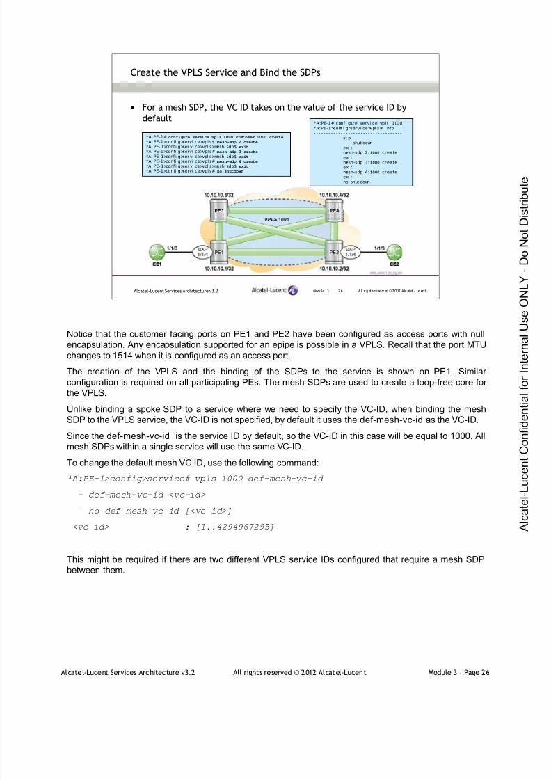
7/21/2019 Services Architecture v3.2 Student Guide Download
http://slidepdf.com/reader/full/services-architecture-v32-student-guide-download 201/429
Alcatel-Lucent Services Architecture v3.2 All rights reserved © 2012 Alcatel-Lucent Module 3 – Page 26
Module 3 | 26 A ll r ights re se rved ©2012 A lcatel -LucentAlcatel-Lucent Services Architecture v3.2
Create the VPLS Service and Bind the SDPs
For a mesh SDP, the VC ID takes on the value of the service ID by
default
*A:PE-1# configure service vpls 1000 customer 1000 create*A: PE-1>confi g>servi ce>vpl s$ mesh-sdp 2 create
*A: PE- 1>conf i g>ser vi ce>vpl s>mesh- sdp$ exit
*A: PE-1>confi g>servi ce>vpl s# mesh-sdp 3 create
*A: PE- 1>conf i g>ser vi ce>vpl s>mesh- sdp$ exit
*A: PE-1>confi g>servi ce>vpl s# mesh-sdp 4 create
*A: PE- 1>conf i g>ser vi ce>vpl s>mesh- sdp$ exit
*A: PE-1>confi g>servi ce>vpl s# no shutdown
*A:PE-1# confi gure servi ce vpls 1000*A:PE-1>conf i g>servi ce>vpl s# i nfo- - - - - - - - - - - - - - - - - - - - - - - - - - - - - - - - - - - -
st pshut down
exi tmesh-sdp 2:1000 createexi tmesh-sdp 3:1000 createexi tmesh-sdp 4:1000 createexi tno shut down
Notice that the customer facing ports on PE1 and PE2 have been configured as access ports with null
encapsulation. Any encapsulation supported for an epipe is possible in a VPLS. Recall that the port MTU
changes to 1514 when it is configured as an access port.
The creation of the VPLS and the binding of the SDPs to the service is shown on PE1. Similar
configuration is required on all participating PEs. The mesh SDPs are used to create a loop-free core for
the VPLS.
Unlike binding a spoke SDP to a service where we need to specify the VC-ID, when binding the meshSDP to the VPLS service, the VC-ID is not specified, by default it uses the def-mesh-vc-id as the VC-ID.
Since the def-mesh-vc-id is the service ID by default, so the VC-ID in this case will be equal to 1000. All
mesh SDPs within a single service will use the same VC-ID.
To change the default mesh VC ID, use the following command:
*A:PE-1>config>service# vpls 1000 def-mesh-vc-id
- def-mesh-vc-id <vc-id>
- no def-mesh-vc-id [<vc-id>]
<vc-id> : [1..4294967295]
This might be required if there are two different VPLS service IDs configured that require a mesh SDP
between them.

7/21/2019 Services Architecture v3.2 Student Guide Download
http://slidepdf.com/reader/full/services-architecture-v32-student-guide-download 202/429
Alcatel-Lucent Services Architecture v3.2 All rights reserved © 2012 Alcatel-Lucent Module 3 – Page 27
Module 3 | 27 A ll r ights re se rved ©2012 A lcatel -LucentAlcatel-Lucent Services Architecture v3.2
Create the VPLS Service and Bind the SDPs (continued)
VPLS configuration and SDP bindings on all participating PE routers
*A:PE-1#confi gure servi ce vpl s 1000*A:PE-1>confi g>servi ce>vpl s# i nfo- - - - - - - - - - - - - - - - - - - - - - - - - - - - - - - - - - - -
st pshut down
exi tmesh-sdp 2:1000 creat eexi tmesh-sdp 3:1000 creat eexi tmesh-sdp 4:1000 creat eexi tno shut down
- - - - - - - - - - - - - - - - - - - - - - - - - - - - - - - - - - - -
*A:PE-2# confi gure servi ce vpls 1000*A:PE-2>confi g>servi ce>vpls# i nfo- - - - - - - - - - - - - - - - - - - - - - - - - - - - - - - - - - - - -
st pshut down
exi tmesh-sdp 1:1000 creat eexi tmesh-sdp 3:1000 creat eexi tmesh-sdp 4:1000 creat eexi tno shut down
- - - - - - - - - - - - - - - - - - - - - - - - - - - - - - - - - - - - -
A full mesh of SDPs is required for the VPLS. The VPLS ID is the same in all four PEs. All mesh SDPs
use the same VC ID. A mesh SDP must be established in both directions before it becomes operational.
The configuration shown is on PE1 and PE2. The configuration PE3 and PE4 are similar as shown below:
*A: PE- 3>conf i g>ser vi ce>vpl s# i nf o *A: PE- 4>conf i g>ser vi ce>vpl s# i nf o
- - - - - - - - - - - - - - - - - - - - - - - - - - - - - - - - - - - - - - - - - - - - - - - - - - - - - - - - - - - - - - - - - - - - - - - - - -
st p st p
shut down shut down
exi t exi t
mesh- sdp 1: 1000 cr eat e mesh- sdp 1: 1000 cr eat e
exi t exi t
mesh- sdp 2: 1000 cr eat e mesh- sdp 2: 1000 cr eat e
exi t exi t
mesh- sdp 4: 1000 cr eat e mesh- sdp 3: 1000 cr eat e
exi t exi t
no shut down no shut down

7/21/2019 Services Architecture v3.2 Student Guide Download
http://slidepdf.com/reader/full/services-architecture-v32-student-guide-download 203/429
Alcatel-Lucent Services Architecture v3.2 All rights reserved © 2012 Alcatel-Lucent Module 3 – Page 28
Module 3 | 28 A ll r ights re se rved ©2012 A lcatel -LucentAlcatel-Lucent Services Architecture v3.2
Verify the Mesh SDPs
The mesh SDPs are operationally up
An ingress and an egress service label have been signaled
*A:PE-1# show servi ce id 1000 sdp=============================================================================Servi ces: Servi ce Desti nati on Points=============================================================================SdpI d Type I P address Adm Opr I . Lbl E. Lbl- - - - - - - - - - - - - - - - - - - - - - - -- - - - - - - - - - - - - - - - - - - - - - - -- - - - - - - - - - - - - - - - - - - - - - - - -- - - -2 :1000 Mesh 10.10.10.2 Up Up 131068 1310683: 1000 Mesh 10.10. 10. 3 Up Up 131067 131068
4:1000 Mesh 10.10.10.4 Up Up 131063 131065- - - - - - - - - - - - - - - - - - - - - - - -- - - - - - - - - - - - - - - - - - - - - - - -- - - - - - - - - - - - - - - - - - - - - - - - -- - - -Number of SDPs : 3
*A:PE-3# show servi ce id 1000 sdp=============================================================================Servi ces: Servi ce Desti nati on Points=============================================================================SdpI d Type I P address Adm Opr I . Lbl E. Lbl- - - - - - - - - - - - - - - - - - - - - - - -- - - - - - - - - - - - - - - - - - - - - - - -- - - - - - - - - - - - - - - - - - - - - - - - -- - - -1: 1000 Mesh 10.10. 10. 1 Up Up 131068 131067
2:1000 Mesh 10.10.10.2 Up Up 131065 1310644:1000 Mesh 10.10.10.4 Up Up 131067 131067- - - - - - - - - - - - - - - - - - - - - - - -- - - - - - - - - - - - - - - - - - - - - - - -- - - - - - - - - - - - - - - - - - - - - - - - -- - - -
- -Number of SDPs : 3
After the VPLS 1000 is configured on the other PE routers and the service is bound to the SDPs, the PEs
have signaled a label for VC-ID 1000, which creates an ingress and an egress service label binding.
A VC label will only be signaled when a service is bound to a SDP. For example, if we shutdown the mesh
SDP binding on PE-2 towards PE-1.
*A: PE- 2>conf i g>ser vi ce>vpl s# mesh- sdp 1 shut down
We notice that PE-1 does not have an egress VC label, and the flag for the SDP shows NoEgrVCLabelbecause there has been no label signaled by PE-2.
*A:PE-1# show service id 1000 sdp 2
===============================================================================
Ser vi ce Dest i nat i on Poi nt ( Sdp I d : 2)
===============================================================================
SdpI d Type I P addr ess Adm Opr I . Lbl E. Lbl
- - - - - - - - - - - - - - - - - - - - - - - - - - - - - - - - - - - - - - - - - - - - - - - - - - - - - - - - - - - - - - - - - - - - - - - - - - - - - - -
2: 1000 Mesh 10. 10. 10. 2 Up Down 131068 0
===============================================================================
*A:PE-1# show service id 1000 sdp 2 detail
===============================================================================
Servi ce Desti nat i on Poi nt ( Sdp I d : 2) Det ai l s
===============================================================================
Sdp I d 2: 1000 - ( 10. 10. 10. 2)
- - - - - - - - - - - - - - - - - - - - - - - - - - - - - - - - - - - - - - - - - - - - - - - - - - - - - - - - - - - - - - - - - - - - - - - - - - - - - - -
Descri pt i on : ( Not Speci f i ed)
SDP I d : 2: 1000 Type : Mesh
…
VC Type : Ether VC Tag : n/ a
Admi n Pat h MTU : 0 Oper Pat h MTU : 9190
Far End : 10. 10. 10. 2 Del i ver y : MPLS
…
I ngr ess Label : 131068 Egress Label : 0
…
Fl ags : NoEgrVCLabel
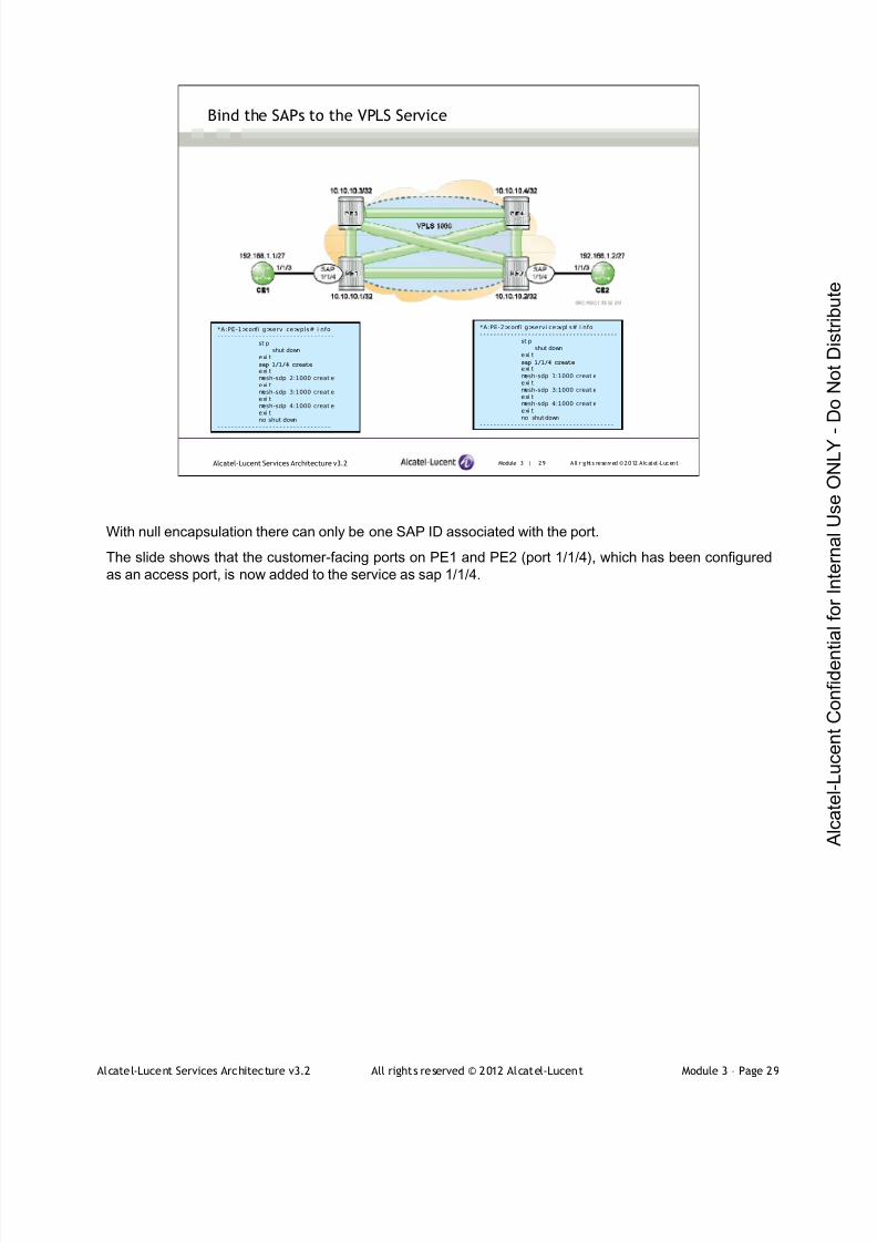
7/21/2019 Services Architecture v3.2 Student Guide Download
http://slidepdf.com/reader/full/services-architecture-v32-student-guide-download 204/429
Alcatel-Lucent Services Architecture v3.2 All rights reserved © 2012 Alcatel-Lucent Module 3 – Page 29
Module 3 | 29 A ll r ights re se rved ©2012 A lcatel -LucentAlcatel-Lucent Services Architecture v3.2
Bind the SAPs to the VPLS Service
*A:PE-1>confi g>servi ce>vpls# i nfo- - - - - - - - - - - - - - - - - - - - - - - - - - - - - - - - - -
st pshut down
exi tsap 1/1/4 create
exi tmesh-sdp 2:1000 creat eexi tmesh-sdp 3:1000 creat eexi tmesh-sdp 4:1000 creat eexi tno shut down
- - - - - - - - - - - - - - - - - - - - - - - - - - - - - - - - -
*A:PE-2>confi g>servi ce>vpl s# i nfo- - - - - - - - - - - - - - - - - - - - - - - - - - - - - - - - - - - - - - - -
st pshut down
exi t
sap 1/1/4 createexi tmesh-sdp 1:1000 creat eexi tmesh-sdp 3:1000 creat eexi tmesh-sdp 4:1000 creat eexi tno shut down
- - - - - - - - - - - - - - - - - - - - - - - - - - - - - - - - - - - - - - -
With null encapsulation there can only be one SAP ID associated with the port.
The slide shows that the customer-facing ports on PE1 and PE2 (port 1/1/4), which has been configured
as an access port, is now added to the service as sap 1/1/4.

7/21/2019 Services Architecture v3.2 Student Guide Download
http://slidepdf.com/reader/full/services-architecture-v32-student-guide-download 205/429
Alcatel-Lucent Services Architecture v3.2 All rights reserved © 2012 Alcatel-Lucent Module 3 – Page 30
Module 3 | 30 A ll r ights re se rved ©2012 A lcatel -LucentAlcatel-Lucent Services Architecture v3.2
Verify the VPLS Service
*A:PE-1# show servi ce i d 1000 base===============================================================================Servi ce Basi c Inf ormati on===============================================================================
Servi ce I d : 1000 Vpn Id : 0Servi ce Type : VPLSName : ( Not Speci f i ed)Descri pti on : (Not Speci fi ed)Cust omer I d : 1000Last Stat us Change: 02/ 17/ 2012 12: 20: 24Last Mgmt Change : 02/ 21/2012 16:40: 17Admi n State : Up Oper State : UpMTU : 1514 Def. Mesh VC I d : 1000
SAP Count : 1 SDP Bi nd Count : 3
Snd Fl ush on Fail : Di sabl ed Host Conn Veri f y : Di sabl edPropagate MacFl ush: Di sabl ed Per Svc Hashi ng : Di sabl edDef . Gat eway I P : NoneDef. Gateway MAC : None- - - - - - - - - - - - - - - - - - - - - - - - - - - - - - - - - - - - - - - - - - - - - - - - - - - - - - - - - - - - - - - - - - - - - - - - - - - - - - -Servi ce Access & Desti nati on Poi nts- - - - - - - - - - - - - - - - - - - - - - - - - - - - - - - - - - - - - - - - - - - - - - - - - - - - - - - - - - - - - - - - - - - - - - - - - - - - - - -I denti fi er Type AdmMTU OprMTU Adm Opr- - - - - - - - - - - - - - - - - - - - - - - - - - - - - - - - - - - - - - - - - - - - - - - - - - - - - - - - - - - - - - - - - - - - - - - - - - - - - - -sap:1/1/4 nul l 1514 1514 Up Upsdp:2:1000 M( 10. 10.10. 2) Mesh 0 9190 Up Upsdp:3:1000 M( 10. 10.10. 3) Mesh 0 9190 Up Upsdp:4:1000 M( 10. 10.10. 4) Mesh 0 9190 Up Up===============================================================================
Once the service is configured on the other PE devices, the VPLS is operationally up.
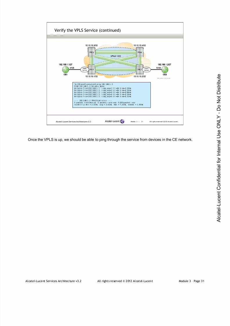
7/21/2019 Services Architecture v3.2 Student Guide Download
http://slidepdf.com/reader/full/services-architecture-v32-student-guide-download 206/429
Alcatel-Lucent Services Architecture v3.2 All rights reserved © 2012 Alcatel-Lucent Module 3 – Page 31
Module 3 | 31 A ll r ights re se rved ©2012 A lcatel -LucentAlcatel-Lucent Services Architecture v3.2
Verify the VPLS Service (continued)
*A: CE1>confi g>rout er# pi ng 192. 168.1. 2PI NG 192. 168.1. 2 56 dat a bytes64 byt es f r om192.168.1. 2: i cmp_seq=1 t t l =64 ti me=7.20ms.64 byt es f r om192.168.1. 2: i cmp_seq=2 t t l =64 ti me=2.34ms.64 byt es f r om192.168.1. 2: i cmp_seq=3 t t l =64 ti me=2.88ms.64 byt es f r om192.168.1. 2: i cmp_seq=4 t t l =64 ti me=2.34ms.64 byt es f r om192.168.1. 2: i cmp_seq=5 t t l =64 ti me=2.32ms.
- - - - 192.168.1 .2 PIN GStat i s t ic s - - - -5 packets t ransmi tt ed, 5 packets r ecei ved, 0.00%packet l ossround-t ri p mi n = 2.32ms, avg = 3.42ms, max = 7.20ms, stddev = 1.90ms
Once the VPLS is up, we should be able to ping through the service from devices in the CE network.
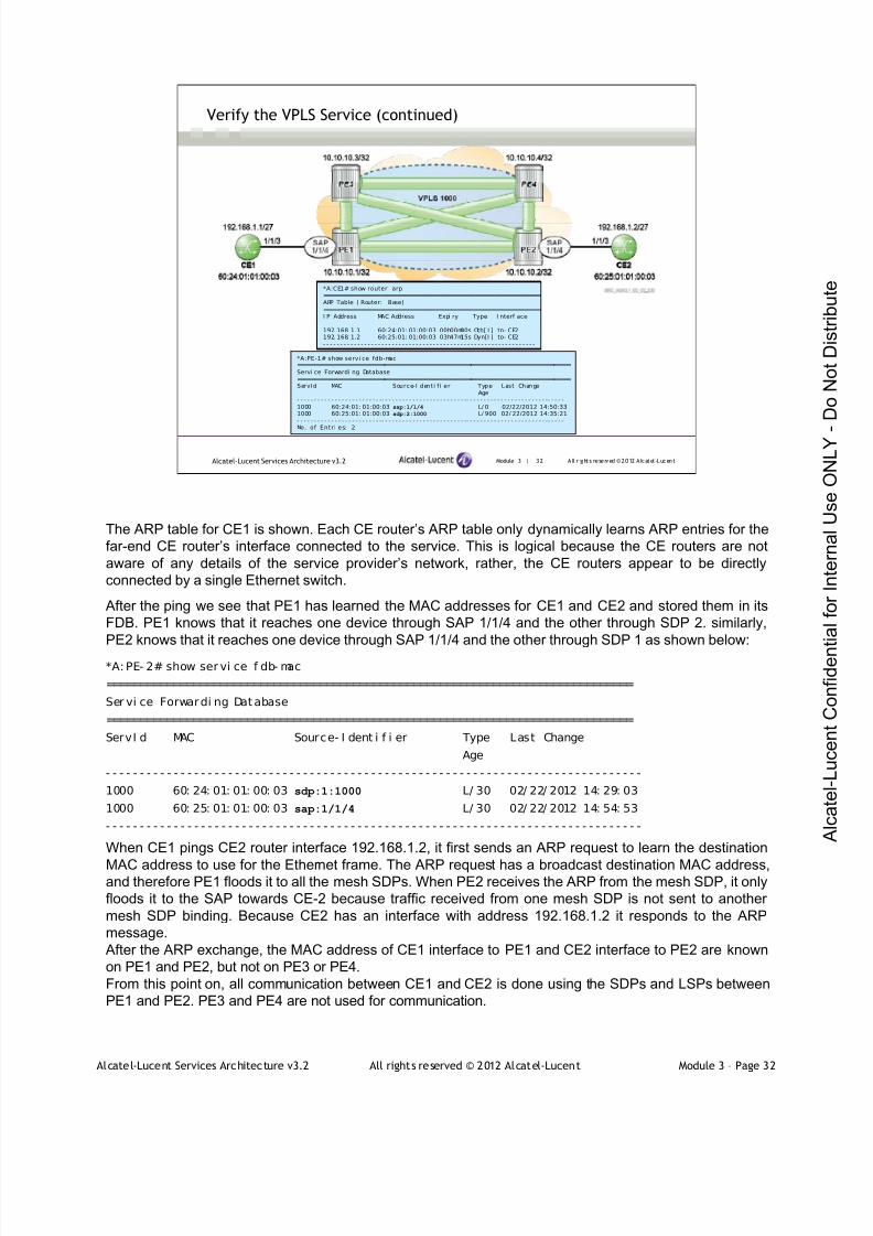
7/21/2019 Services Architecture v3.2 Student Guide Download
http://slidepdf.com/reader/full/services-architecture-v32-student-guide-download 207/429
Alcatel-Lucent Services Architecture v3.2 All rights reserved © 2012 Alcatel-Lucent Module 3 – Page 32
Module 3 | 32 A ll r ights re se rved ©2012 A lcatel -LucentAlcatel-Lucent Services Architecture v3.2
Verify the VPLS Service (continued)
*A:CE1# show router arp==============================================================ARP Table ( Router: Base)==============================================================I P Address MAC Address Expi ry Type I nterf ace- - - - - - - - - - - - - - - - - - - - - - - - - - - - - - - - - - - - - - - - - - - - - - - - - - - - - - - - - - - - - -192. 168. 1.1 60:24:01: 01:00:03 00h00m00s Oth[ I ] to- CE2192. 168. 1.2 60:25:01: 01:00:03 03h47m15s Dyn[I ] to- CE2- - - - - - - - - - - - - - - - - - - - - - - - - - - - - - - - - - - - - - - - - - - - - - - - - - - - - - - - - - - - - -
*A:PE-1# show servi ce fdb-mac===============================================================================Servi ce Forwardi ng Database===============================================================================ServId MAC Source-I denti f i er Type Last Change
Age- - - - - - - - - - - - - - - - - - - - - - - - -- - - - - - - - - - - - - - - - - - - - - - - - -- - - - - - - - - - - - - - - - - - - - - - - -- - - - -1000 60:24:01: 01:00:03 sap:1/1/4 L/ 0 02/22/2012 14:50:331000 60:25:01: 01:00:03 sdp:2:1000 L/ 900 02/ 22/2012 14:35:21- - - - - - - - - - - - - - - - - - - - - - - - -- - - - - - - - - - - - - - - - - - - - - - - - -- - - - - - - - - - - - - - - - - - - - - - - -- - - - -No. of Entri es: 2
The ARP table for CE1 is shown. Each CE router’s ARP table only dynamically learns ARP entries for the
far-end CE router’s interface connected to the service. This is logical because the CE routers are not
aware of any details of the service provider’s network, rather, the CE routers appear to be directly
connected by a single Ethernet switch.
After the ping we see that PE1 has learned the MAC addresses for CE1 and CE2 and stored them in its
FDB. PE1 knows that it reaches one device through SAP 1/1/4 and the other through SDP 2. similarly,
PE2 knows that it reaches one device through SAP 1/1/4 and the other through SDP 1 as shown below:
*A: PE- 2# show ser vi ce f db- mac
===============================================================================
Ser vi ce Forwardi ng Database
===============================================================================
ServI d MAC Source- I dent i f i er Type Last Change
Age
- - - - - - - - - - - - - - - - - - - - - - - - - - - - - - - - - - - - - - - - - - - - - - - - - - - - - - - - - - - - - - - - - - - - - - - - - - - - - - -
1000 60: 24: 01: 01: 00: 03 sdp:1:1000 L/ 30 02/ 22/ 2012 14: 29: 03
1000 60: 25: 01: 01: 00: 03 sap:1/1/4 L/ 30 02/ 22/ 2012 14: 54: 53
- - - - - - - - - - - - - - - - - - - - - - - - - - - - - - - - - - - - - - - - - - - - - - - - - - - - - - - - - - - - - - - - - - - - - - - - - - - - - - -
When CE1 pings CE2 router interface 192.168.1.2, it first sends an ARP request to learn the destination
MAC address to use for the Ethernet frame. The ARP request has a broadcast destination MAC address,and therefore PE1 floods it to all the mesh SDPs. When PE2 receives the ARP from the mesh SDP, it only
floods it to the SAP towards CE-2 because traffic received from one mesh SDP is not sent to another
mesh SDP binding. Because CE2 has an interface with address 192.168.1.2 it responds to the ARP
message.
After the ARP exchange, the MAC address of CE1 interface to PE1 and CE2 interface to PE2 are known
on PE1 and PE2, but not on PE3 or PE4.
From this point on, all communication between CE1 and CE2 is done using the SDPs and LSPs between
PE1 and PE2. PE3 and PE4 are not used for communication.
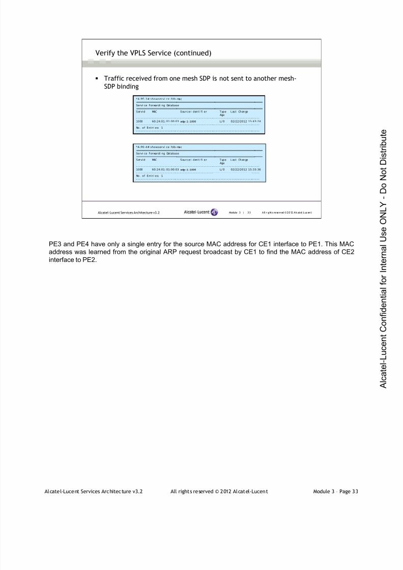
7/21/2019 Services Architecture v3.2 Student Guide Download
http://slidepdf.com/reader/full/services-architecture-v32-student-guide-download 208/429
Alcatel-Lucent Services Architecture v3.2 All rights reserved © 2012 Alcatel-Lucent Module 3 – Page 33
Module 3 | 33 A ll r ights re se rved ©2012 A lcatel -LucentAlcatel-Lucent Services Architecture v3.2
Verify the VPLS Service (continued)
*A:PE-3# showservi ce fdb-mac===============================================================================Servi ce Forwardi ng Database===============================================================================ServId MAC Source-I denti f i er Type Last Change
Age- - - - - - - - - - - - - - - - - - - - - - - - -- - - - - - - - - - - - - - - - - - - - - - - -- - - - - - - - - - - - - - - - - - - - - - - - -- - - - -1000 60:24:01: 01:00:03 sdp:1:1000 L/ 0 02/22/2012 15:43:24- - - - - - - - - - - - - - - - - - - - - - - - -- - - - - - - - - - - - - - - - - - - - - - - -- - - - - - - - - - - - - - - - - - - - - - - - -- - - - -No. of Entri es: 1- - - - - - - - - - - - - - - - - - - - - - - - -- - - - - - - - - - - - - - - - - - - - - - - -- - - - - - - - - - - - - - - - - - - - - - - - -- - - - -
*A:PE-4# showservi ce fdb-mac===============================================================================Servi ce Forwardi ng Database===============================================================================ServId MAC Source-I denti f i er Type Last Change
Age- - - - - - - - - - - - - - - - - - - - - - - - -- - - - - - - - - - - - - - - - - - - - - - - -- - - - - - - - - - - - - - - - - - - - - - - - -- - - - -1000 60:24:01: 01:00:03 sdp:1:1000 L/ 0 02/22/2012 15:33:36- - - - - - - - - - - - - - - - - - - - - - - - -- - - - - - - - - - - - - - - - - - - - - - - -- - - - - - - - - - - - - - - - - - - - - - - - -- - - - -No. of Entri es: 1- - - - - - - - - - - - - - - - - - - - - - - - -- - - - - - - - - - - - - - - - - - - - - - - -- - - - - - - - - - - - - - - - - - - - - - - - -- - - - -
Traffic received from one mesh SDP is not sent to another mesh-
SDP binding
PE3 and PE4 have only a single entry for the source MAC address for CE1 interface to PE1. This MAC
address was learned from the original ARP request broadcast by CE1 to find the MAC address of CE2
interface to PE2.

7/21/2019 Services Architecture v3.2 Student Guide Download
http://slidepdf.com/reader/full/services-architecture-v32-student-guide-download 209/429
Alcatel-Lucent Services Architecture v3.2 All rights reserved © 2012 Alcatel-Lucent Module 3 – Page 34
Module 3 | 34 A ll r ights re se rved ©2012 A lcatel -LucentAlcatel-Lucent Services Architecture v3.2
Lab 3 ― Configuring a VPLS
In this lab you will:
Configure and verify a VPLS service
Explore some of the different possibilities for SAP encapsulation

7/21/2019 Services Architecture v3.2 Student Guide Download
http://slidepdf.com/reader/full/services-architecture-v32-student-guide-download 210/429
Alcatel-Lucent Services Architecture v3.2 All rights reserved © 2012 Alcatel-Lucent Module 3 – Page 35
Module 3 — Introduction to VPLS
Section 3 — VPLS Network Topologies
7/21/2019 Services Architecture v3.2 Student Guide Download
http://slidepdf.com/reader/full/services-architecture-v32-student-guide-download 211/429
Alcatel-Lucent Services Architecture v3.2 All rights reserved © 2012 Alcatel-Lucent Module 3 – Page 36
Module 3 | 36 A ll r ights re se rved ©2012 A lcatel -LucentAlcatel-Lucent Services Architecture v3.2
Section Objectives
After successfully completing this section, you will be able to:
Explain the operation of a hub and spoke VPLS
Explain the operation of a hierarchical VPLS
Explain the operation of a spoke termination on a VPLS
Configure and verify a spoke SDP termination on a VPLS
Complete Lab 4 — Spoke Termination to a VPLS

7/21/2019 Services Architecture v3.2 Student Guide Download
http://slidepdf.com/reader/full/services-architecture-v32-student-guide-download 212/429
Alcatel-Lucent Services Architecture v3.2 All rights reserved © 2012 Alcatel-Lucent Module 3 – Page 37
A VPLS can span a single router or multiple routers. On a VPLS that spans a single router, subscriber
data is distributed through multiple service access points (SAPs) on the router. A VPLS on a single router
does not require a service distribution path (SDP).
On a VPLS that spans multiple sites, customer data enters the service using at least one SAP on each
router. Data is transported among the routers through service tunnels over an IP/MPLS provider core
network. Core VPLS networks are typically fully meshed using mesh SDPs, which means that there is an
SDP binding from every router to every other service-aware router. No Layer 2 loops are present.
So far, the VPLS topologies we have seen in the previous sections use fully meshed topology. This is a
simple and reliable approach to provisioning a VPLS. However, there are circumstances where other,
more complex topologies are preferred. These topologies are introduced in the following slides.
Module 3 | 37 A ll r ights re se rved ©2012 A lcatel -LucentAlcatel-Lucent Services Architecture v3.2
Fully Meshed VPLS
Fully meshed VPLS is a simple and reliable approach to provision a
VPLS
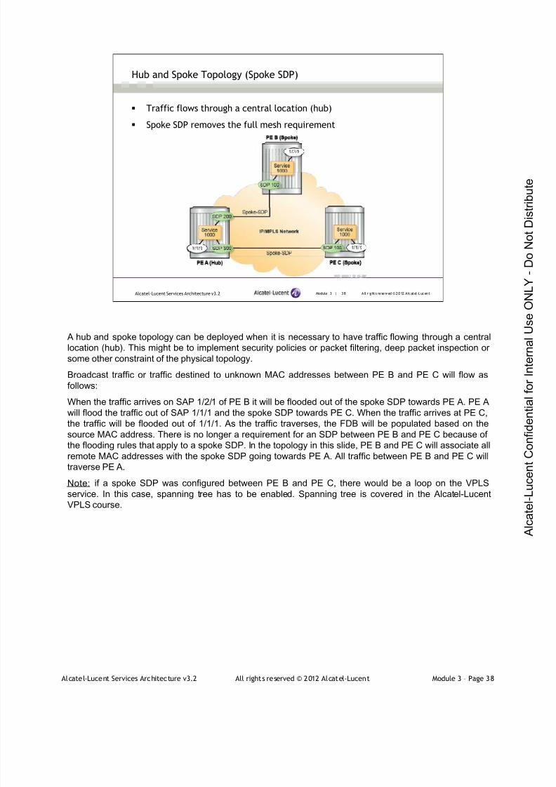
7/21/2019 Services Architecture v3.2 Student Guide Download
http://slidepdf.com/reader/full/services-architecture-v32-student-guide-download 213/429
Alcatel-Lucent Services Architecture v3.2 All rights reserved © 2012 Alcatel-Lucent Module 3 – Page 38
Module 3 | 38 A ll r ights re se rved ©2012 A lcatel -LucentAlcatel-Lucent Services Architecture v3.2
Hub and Spoke Topology (Spoke SDP)
Traffic flows through a central location (hub)
Spoke SDP removes the full mesh requirement
A hub and spoke topology can be deployed when it is necessary to have traffic flowing through a central
location (hub). This might be to implement security policies or packet filtering, deep packet inspection or
some other constraint of the physical topology.
Broadcast traffic or traffic destined to unknown MAC addresses between PE B and PE C will flow as
follows:
When the traffic arrives on SAP 1/2/1 of PE B it will be flooded out of the spoke SDP towards PE A. PE A
will flood the traffic out of SAP 1/1/1 and the spoke SDP towards PE C. When the traffic arrives at PE C,the traffic will be flooded out of 1/1/1. As the traffic traverses, the FDB will be populated based on the
source MAC address. There is no longer a requirement for an SDP between PE B and PE C because of
the flooding rules that apply to a spoke SDP. In the topology in this slide, PE B and PE C will associate all
remote MAC addresses with the spoke SDP going towards PE A. All traffic between PE B and PE C will
traverse PE A.
Note: if a spoke SDP was configured between PE B and PE C, there would be a loop on the VPLS
service. In this case, spanning tree has to be enabled. Spanning tree is covered in the Alcatel-Lucent
VPLS course.
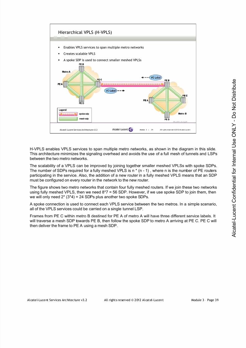
7/21/2019 Services Architecture v3.2 Student Guide Download
http://slidepdf.com/reader/full/services-architecture-v32-student-guide-download 214/429
Alcatel-Lucent Services Architecture v3.2 All rights reserved © 2012 Alcatel-Lucent Module 3 – Page 39
Module 3 | 39 A ll r ights re se rved ©2012 A lcatel -LucentAlcatel-Lucent Services Architecture v3.2
Hierarchical VPLS (H-VPLS)
Enables VPLS services to span multiple metro networks
Creates scalable VPLS
A spoke SDP is used to connect smaller meshed VPLSs
H-VPLS enables VPLS services to span multiple metro networks, as shown in the diagram in this slide.
This architecture minimizes the signaling overhead and avoids the use of a full mesh of tunnels and LSPs
between the two metro networks.
The scalability of a VPLS can be improved by joining together smaller meshed VPLSs with spoke SDPs.
The number of SDPs required for a fully meshed VPLS is n * (n - 1) , where n is the number of PE routers
participating in the service. Also, the addition of a new router in a fully meshed VPLS means that an SDP
must be configured on every router in the network to the new router.
The figure shows two metro networks that contain four fully meshed routers. If we join these two networks
using fully meshed VPLS, then we need 8*7 = 56 SDP. However, if we use spoke SDP to join them, then
we will only need 2* (3*4) = 24 SDPs plus another two spoke SDPs.
A spoke connection is used to connect each VPLS service between the two metros. In a simple scenario,
all of the VPLS services could be carried on a single tunnel LSP.
Frames from PE C within metro B destined for PE A of metro A will have three different service labels. It
will traverse a mesh SDP towards PE B, then follow the spoke SDP to metro A arriving at PE C. PE C will
then deliver the frame to PE A using a mesh SDP.

7/21/2019 Services Architecture v3.2 Student Guide Download
http://slidepdf.com/reader/full/services-architecture-v32-student-guide-download 215/429
Alcatel-Lucent Services Architecture v3.2 All rights reserved © 2012 Alcatel-Lucent Module 3 – Page 40
Module 3 | 40 A ll r ights re se rved ©2012 A lcatel -LucentAlcatel-Lucent Services Architecture v3.2
Spoke SDP Termination on VPWS
Connects a spoke SDP of a VPLS service with an epipe service
Using a spoke SDP reduces the number of SDPs required and simplifies the addition of new routers.
Traffic to be terminated on a given VPLS service is identified by the VC label present in the service packet,
as if it was connected to another VPLS service spoke SDP.

7/21/2019 Services Architecture v3.2 Student Guide Download
http://slidepdf.com/reader/full/services-architecture-v32-student-guide-download 216/429
Alcatel-Lucent Services Architecture v3.2 All rights reserved © 2012 Alcatel-Lucent Module 3 – Page 41
Module 3 | 41 A ll r ights re se rved ©2012 A lcatel -LucentAlcatel-Lucent Services Architecture v3.2
Spoke SDP Termination on VPWS (continued)
The VC-ID of the spoke SDPs on the epipe service and the VPLS service must match
VC-ID (100) does not have to match the service ID of either the epipe or the VPLS
The service MTU of the VPLS and epipe service must match
The VC-ID of the spoke SDPs on the epipe service and the VPLS service must match. Recall that the VC-
ID has point-to-point significance. Also note that the VC-ID (100) does not have to match the service ID of
either the epipe or the VPLS as long as both ends are the same.
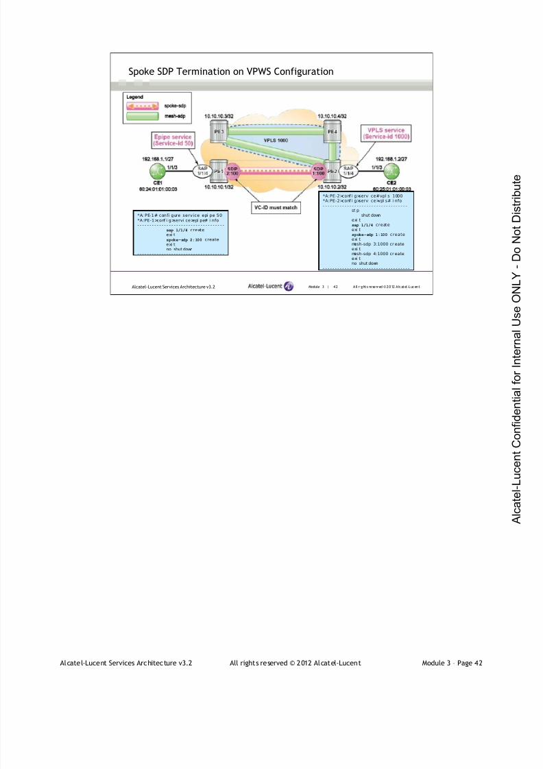
7/21/2019 Services Architecture v3.2 Student Guide Download
http://slidepdf.com/reader/full/services-architecture-v32-student-guide-download 217/429
Alcatel-Lucent Services Architecture v3.2 All rights reserved © 2012 Alcatel-Lucent Module 3 – Page 42
Module 3 | 42 A ll r ights re se rved ©2012 A lcatel -LucentAlcatel-Lucent Services Architecture v3.2
Spoke SDP Termination on VPWS Configuration
*A: PE-1# confi gure service epi pe 50*A:PE-1>conf i g>servi ce>epi pe# i nfo- - - - - - - - - - - - - - - - - - - - - - - - - - - - - - - - - - - -
sap 1/1/4 createexi tspoke-sdp 2:100 createexi tno shut down
- - - - - - - - - - - - - - - - - - - - - - - - - - - - - - - - - - - -
*A:PE-2>conf i g>servi ce#vpl s 1000*A:PE-2>conf i g>servi ce>vpl s# i nfo- - - - - - - - - - - - - - - - - - - - - - - - - - - - - - - - - - -
st pshut down
exi tsap 1/1/4 createexi tspoke-sdp 1:100 createexi tmesh-sdp 3:1000 cr eateexi tmesh-sdp 4:1000 cr eateexi tno shut down
- - - - - - - - - - - - - - - - - - - - - - - - - - - - - - - - - - - -
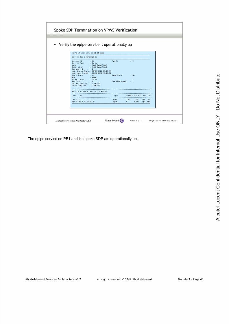
7/21/2019 Services Architecture v3.2 Student Guide Download
http://slidepdf.com/reader/full/services-architecture-v32-student-guide-download 218/429
Alcatel-Lucent Services Architecture v3.2 All rights reserved © 2012 Alcatel-Lucent Module 3 – Page 43
Module 3 | 43 A ll r ights re se rved ©2012 A lcatel -LucentAlcatel-Lucent Services Architecture v3.2
Spoke SDP Termination on VPWS Verification
Verify the epipe service is operationally up
*A:PE-1# show servi ce id 50 base===============================================================================
Servi ce Basi c Inf ormati on===============================================================================Service Id : 50 Vpn Id : 0Servi ce Type : Epi peName : (Not Speci f i ed)Descri pti on : (Not Speci f i ed)Cust omer I d : 1Last Stat us Change: 02/ 23/ 2012 13: 11: 39Last Mgmt Change : 02/23/ 2012 13: 11:39Admi n State : Up Oper State : Up
MTU : 1514
Vc Swi tching : Fal seSAP Count : 1 SDP Bi nd Count : 1Per Svc Hashi ng : Di sabl edForce QTag Fwd : Di sabl ed
- - - - - - - - - - - - - - - - - - - - - - - - - - - - - - - - - - - - - - - - - - - - - - - - - - - - - - - - - - - - - - - - - - - - - - - - - - - - - - -Servi ce Access & Desti nati on Points- - - - - - - - - - - - - - - - - - - - - - - - - - - - - - - - - - - - - - - - - - - - - - - - - - - - - - - - - - - - - - - - - - - - - - - - - - - - - - -I denti fi er Type AdmMTU OprMTU Adm Opr- - - - - - - - - - - - - - - - - - - - - - - - - - - - - - - - - - - - - - - - - - - - - - - - - - - - - - - - - - - - - - - - - - - - - - - - - - - - - - -sap:1/1/4 nul l 1514 1514 Up Upsdp:2:100 S( 10. 10. 10. 2) Spok 0 9190 Up Up===============================================================================
The epipe service on PE1 and the spoke SDP are operationally up.

7/21/2019 Services Architecture v3.2 Student Guide Download
http://slidepdf.com/reader/full/services-architecture-v32-student-guide-download 219/429
Alcatel-Lucent Services Architecture v3.2 All rights reserved © 2012 Alcatel-Lucent Module 3 – Page 44
Module 3 | 44 A ll r ights re se rved ©2012 A lcatel -LucentAlcatel-Lucent Services Architecture v3.2
Spoke SDP Termination on VPWS Verification (continued)
Verify the VPLS is operationally up
*A:PE-2# show servi ce i d 1000 base===============================================================================
Servi ce Basi c Inf ormati on===============================================================================Service Id : 1000 Vpn Id : 0Servi ce Type : VPLSName : (Not Speci f i ed)Descri pti on : (Not Speci f i ed)Cust omer I d : 1000Last Stat us Change: 02/ 22/ 2012 15: 19: 06Last Mgmt Change : 02/23/ 2012 12: 04:08Admi n State : Up Oper State : Up
MTU : 1514 Def . Mesh VC I d : 1000SAP Count : 1 SDP Bi nd Count : 3Snd Fl ush on Fail : Di sabl ed Host Conn Veri f y : Di sabl edPropagate MacFl ush: Di sabl ed Per Svc Hashi ng : Di sabl edDef. Gateway I P : NoneDef. Gateway MAC : None
- - - - - - - - - - - - - - - - - - - - - - - - - - - - - - - - - - - - - - - - - - - - - - - - - - - - - - - - - - - - - - - - - - - - - - - - - - - - - - -Servi ce Access & Desti nati on Points- - - - - - - - - - - - - - - - - - - - - - - - - - - - - - - - - - - - - - - - - - - - - - - - - - - - - - - - - - - - - - - - - - - - - - - - - - - - - - -I denti fi er Type AdmMTU OprMTU Adm Opr- - - - - - - - - - - - - - - - - - - - - - - - - - - - - - - - - - - - - - - - - - - - - - - - - - - - - - - - - - - - - - - - - - - - - - - - - - - - - - -sap:1/1/4 nul l 1514 1514 Up Upsdp:1:100 S(10.10.10.1) Spok 0 9190 Up Upsdp: 3: 1000 M( 10. 10.10. 3) Mesh 0 9190 Up Upsdp: 4: 1000 M( 10. 10.10. 4) Mesh 0 9190 Up Up===============================================================================
The VPLS on PE2 and spoke SDP bindings are operationally up.

7/21/2019 Services Architecture v3.2 Student Guide Download
http://slidepdf.com/reader/full/services-architecture-v32-student-guide-download 220/429
Alcatel-Lucent Services Architecture v3.2 All rights reserved © 2012 Alcatel-Lucent Module 3 – Page 45
Module 3 | 45 A ll r ights re se rved ©2012 A lcatel -LucentAlcatel-Lucent Services Architecture v3.2
Spoke SDP Termination on VPWS Verification (continued)
The CE devices can successfully communicate with each other
*A:CE1# ping 192. 168.1. 2PI NG 192. 168. 1. 2 56 data byt es64 bytes f r om192. 168. 1. 2: i cmp_seq=1 tt l =64 ti me=6. 62ms.64 bytes f r om192. 168. 1. 2: i cmp_seq=2 tt l =64 ti me=2. 27ms.64 bytes f r om192. 168. 1. 2: i cmp_seq=3 tt l =64 ti me=2. 25ms.64 bytes f r om192. 168. 1. 2: i cmp_seq=4 tt l =64 ti me=2. 94ms.64 bytes f r om192. 168. 1. 2: i cmp_seq=5 tt l =64 ti me=2. 28ms.
- - - - 192.168.1.2 P ING Stat i s t i cs - - - -5 packet s tr ansmi t ted, 5 packet s recei ved, 0. 00% packet l ossround- tr i p mi n =2. 25ms, avg = 3.27ms, max = 6. 62ms, st ddev =
1. 69ms
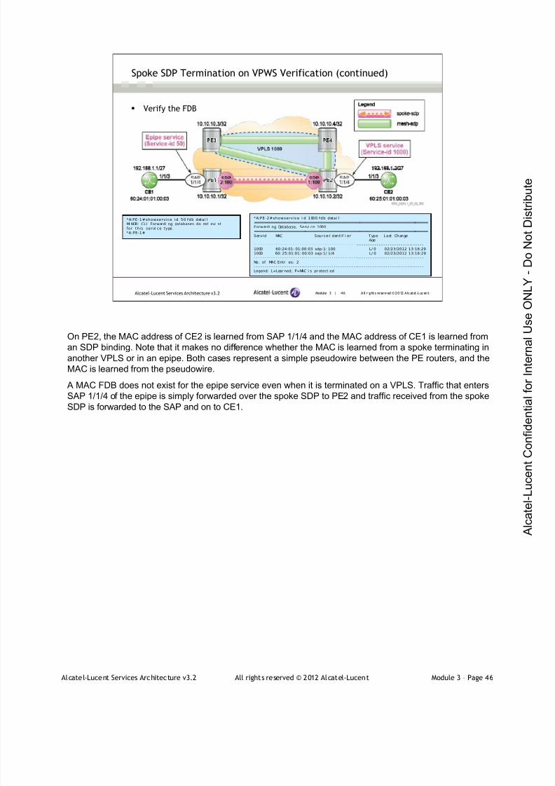
7/21/2019 Services Architecture v3.2 Student Guide Download
http://slidepdf.com/reader/full/services-architecture-v32-student-guide-download 221/429
Alcatel-Lucent Services Architecture v3.2 All rights reserved © 2012 Alcatel-Lucent Module 3 – Page 46
Module 3 | 46 A ll r ights re se rved ©2012 A lcatel -LucentAlcatel-Lucent Services Architecture v3.2
Spoke SDP Termination on VPWS Verification (continued)
Verify the FDB
*A:PE-2#showservice i d 1000 fdb detai l===============================================================================Forwardi ng Database, Servi ce 1000===============================================================================ServId MAC Source-I dentif i er Type Last Change
Age- - - - - - - - - - - - - - - - - - - - - - -- - - - - - - - - - - - - - - - - - - - - - - - -- - - - - - - - - - - - - - - - - - - - - - - - -- - - - - -1000 60:24:01: 01:00:03 sdp:1: 100 L/ 0 02/23/2012 13:16:291000 60: 25:01:01: 00:03 sap:1/ 1/4 L/ 0 02/23/2012 13:16:29- - - - - - - - - - - - - - - - - - - - - - -- - - - - - - - - - - - - - - - - - - - - - - - -- - - - - - - - - - - - - - - - - - - - - - - - -- - - - - -No. of MAC Entr i es: 2- - - - - - - - - - - - - - - - - - - - - - -- - - - - - - - - - - - - - - - - - - - - - - - -- - - - - - - - - - - - - - - - - - - - - - - - -- - - - - -Legend: L=Lear ned; P=MAC i s pr otect ed
*A:PE-1#showservice id 50 fdb detai lMI NOR: CLI Forwardi ng databases do not exi stfor this servi ce type.*A:PE-1#
On PE2, the MAC address of CE2 is learned from SAP 1/1/4 and the MAC address of CE1 is learned from
an SDP binding. Note that it makes no difference whether the MAC is learned from a spoke terminating in
another VPLS or in an epipe. Both cases represent a simple pseudowire between the PE routers, and the
MAC is learned from the pseudowire.
A MAC FDB does not exist for the epipe service even when it is terminated on a VPLS. Traffic that enters
SAP 1/1/4 of the epipe is simply forwarded over the spoke SDP to PE2 and traffic received from the spoke
SDP is forwarded to the SAP and on to CE1.

7/21/2019 Services Architecture v3.2 Student Guide Download
http://slidepdf.com/reader/full/services-architecture-v32-student-guide-download 222/429
Alcatel-Lucent Services Architecture v3.2 All rights reserved © 2012 Alcatel-Lucent Module 3 – Page 47
Module 3 | 47 A ll r ights re se rved ©2012 A lcatel -LucentAlcatel-Lucent Services Architecture v3.2
Spoke SDP Termination on VPWS – VC-ID Mismatch
*A:PE- 1>confi g>servi ce>epipe# spoke-sdp 2:100 shutdown*A:PE- 1>confi g>servi ce>epipe# no spoke-sdp 2:100*A:PE-1>confi g>servi ce>epi pe# spoke-sdp 2:50 create*A:PE- 1>confi g>servi ce>epipe>spoke-sdp$ exi t*A:PE- 1>confi g>servi ce>epipe#i nfo- - - - - - - - - - - - - - - - - - - - - - - - - - - - - - - - - - - - - - - - - - - - - -
sap 1/ 1/4 createexi tspoke-sdp 2:50 createexi tno shut down
*A:PE-1# show servi ce id 50 base
==============================================================================
Servi ce Basic I nformati on
==============================================================================
Servi ce I d : 50 Vpn Id : 0
Servi ce Type : Epipe
…
Admi n Stat e : Up Oper State : Down
MTU : 1514
…
Servi ce Access & Desti nati on Points
- - - - - - - - - - - - - - - - - - - - - - -- - - - - - - - - - - - - - - - - - - - - - - - -- - - - - - - - - - - - - - - - - - - - - - - - -- - - - -
I denti f i er Type AdmMTU OprMTU Adm Opr
- - - - - - - - - - - - - - - - - - - - - - -- - - - - - - - - - - - - - - - - - - - - - - - -- - - - - - - - - - - - - - - - - - - - - - - - -- - - - -
sap:1/1/4 nul l 1514 1514 Up Up
sdp:2:50 S( 10. 10. 10. 2) Spok 0 9190 Up Down
In the configuration shown, we have changed the VC-ID of the spoke SDP of the epipe service to 50. The
VPLS spoke SDP VC-ID remains the same (100).
Note: the epipe service is now operationally down because of the VC-ID mismatch.
The error flag for the SDP shows NoEgrVCLabel.
*A: PE- 1# show ser vi ce i d 50 sdp det ai l
===============================================================================
Ser vi ces: Ser vi ce Dest i nat i on Poi nt s Det ai l s
===============================================================================
Sdp I d 2: 50 - ( 10. 10. 10. 2)
- - - - - - - - - - - - - - - - - - - - - - - - - - - - - - - - - - - - - - - - - - - - - - - - - - - - - - - - - - - - - - - - - - - - - - - - - - - - - - -
Descri pt i on : ( Not Speci f i ed)
SDP I d : 2: 50 Type : Spoke
Spoke Descr : ( Not Speci f i ed)
VC Type : Ether VC Tag : n/ a
Admi n Path MTU : 0 Oper Path MTU : 9190
Far End : 10. 10. 10. 2 Del i ver y : MPLS
Hash Label : Di sabl ed
Admi n State : Up Oper State : Down
Acct . Pol : None Col l ect St at s : Di sabl ed
I ngr ess Label : 131068 Egr ess Label : 0
…
Last St atus Change : 01/ 30/ 2012 16: 55: 09 Si gnal i ng : TLDP
Last Mgmt Change : 02/ 23/ 2012 13: 37: 55 For ce Vl an- Vc : Di sabl ed
Endpoi nt : N/ A Precedence : 4
Cl ass Fwdi ng St ate : Down
Flags : NoEgrVCLabel
Peer Pw Bi t s : None
Peer Faul t I p : None

7/21/2019 Services Architecture v3.2 Student Guide Download
http://slidepdf.com/reader/full/services-architecture-v32-student-guide-download 223/429

7/21/2019 Services Architecture v3.2 Student Guide Download
http://slidepdf.com/reader/full/services-architecture-v32-student-guide-download 224/429
Alcatel-Lucent Services Architecture v3.2 All rights reserved © 2012 Alcatel-Lucent Module 3 – Page 49
Module 3 | 49 A ll r ights re se rved ©2012 A lcatel -LucentAlcatel-Lucent Services Architecture v3.2
Spoke SDP Termination on VPWS – MTU Mismatch
*A:PE- 1>confi g>servi ce>epipe# spoke-sdp 2:50 shutdown*A:PE- 1>confi g>servi ce>epipe# no spoke-sdp 2:50*A:PE-1>confi g>servi ce>epi pe# spoke-sdp 2:100 create*A:PE- 1>confi g>servi ce>epipe>spoke-sdp$ back*A:PE- 1>confi g>servi ce>epipe# servi ce-mtu 1500*A:PE-1>confi g>servi ce>epi pe# i nfo- - - - - - - - - - - - - - - - - - - - - - - - - - - - - - - - - - - - - - - - - - - - - -
servi ce-mtu 1500sap 1/ 1/4 createexi tspoke-sdp 2:100 createexi tno shut down
- - - - - - - - - - - - - - - - - - - - - - - - - - - - - - - - - - - - - - - - - - - - - -
*A:PE-1# show servi ce id 50 base
==============================================================================
Servi ce Basic I nformati on
==============================================================================
Servi ce I d : 50 Vpn Id : 0
Servi ce Type : Epipe
…
Admi n Stat e : Up Oper State : Down
MTU : 1500
…
Servi ce Access & Desti nati on Points
- - - - - - - - - - - - - - - - - - - - - - -- - - - - - - - - - - - - - - - - - - - - - - - -- - - - - - - - - - - - - - - - - - - - - - - - -- - - - -
I denti f i er Type AdmMTU OprMTU Adm Opr
- - - - - - - - - - - - - - - - - - - - - - -- - - - - - - - - - - - - - - - - - - - - - - - -- - - - - - - - - - - - - - - - - - - - - - - - -- - - - -
sap:1/1/4 nul l 1514 1514 Up Up
sdp:2:100 S( 10. 10. 10. 2) Spok 0 9190 Up Down
In the configuration shown, we have changed the VC-ID of the spoke SDP of the epipe service back to 100, howeverwe have changed the service MTU to be 1500 bytes. The VPLS spoke SDP VC-ID and service MTU remain thesame.
Note: the epipe service is now operationally down because of the service MTU mismatch.
The error flag for the SDP shows ServiceMTUMismatch.
*A: PE- 1# show servi ce i d 50 sdp 2 detai l
===============================================================================
Servi ce Desti nat i on Poi nt ( Sdp I d : 2) Det ai l s===============================================================================
Sdp Id 2:100 - ( 10. 10. 10. 2)
- - - - - - - - - - - - - - - - - - - - - - - - - - - - - - - - - - - - - - - - - - - - - - - - - - - - - - - - - - - - - - - - - - - - - - - - - - - - - - -
Descri pt i on : ( Not Speci f i ed)
SDP Id : 2:100 Type : Spoke
Spoke Descr : ( Not Speci f i ed)
VC Type : Ether VC Tag : n/ a
Admi n Pat h MTU : 0 Oper Pat h MTU : 9190
Far End : 10. 10. 10. 2 Del i ver y : MPLS
Hash Label : Di sabl ed
Admi n Stat e : Up Oper State : Down
Acct . Pol : None Col l ect St at s : Di sabl ed
I ngr ess Label : 131062 Egr ess Label : 131068
…
Last Stat us Change : 02/ 23/ 2012 13: 42: 05 Si gnal i ng : TLDP
Last Mgmt Change : 02/ 23/ 2012 13: 42: 05 For ce Vl an- Vc : Di sabl ed
Endpoi nt : N/ A Precedence : 4
Cl ass Fwdi ng St ate : Down
Flags : ServiceMTUMismatch
Peer Pw Bi t s : pwNotForwardi ng
7/21/2019 Services Architecture v3.2 Student Guide Download
http://slidepdf.com/reader/full/services-architecture-v32-student-guide-download 225/429
Alcatel-Lucent Services Architecture v3.2 All rights reserved © 2012 Alcatel-Lucent Module 3 – Page 50
Module 3 | 50 A ll r ights re se rved ©2012 A lcatel -LucentAlcatel-Lucent Services Architecture v3.2
Module Summary
VPLS is a class of VPN that allows the connection of multiple
sites in a single-bridged domain over a provider-managed
IP/MPLS network VPLS emulates a virtual Ethernet switch, in particular its MAC
learning and flooding behavior
VPLS uses T-LDP for signaling service labels
By default, the VC ID equals the service ID in mesh SDP
A VPLS can span a single router or multiple routers
Spoke SDPs and mesh SDPs can be used together to form
hierarchical VPLS topologies

7/21/2019 Services Architecture v3.2 Student Guide Download
http://slidepdf.com/reader/full/services-architecture-v32-student-guide-download 226/429
Alcatel-Lucent Services Architecture v3.2 All rights reserved © 2012 Alcatel-Lucent Module 3 – Page 51
Module 3 | 51 A ll r ights re se rved ©2012 A lcatel -LucentAlcatel-Lucent Services Architecture v3.2
Module Summary (Continued)
Hub and spoke topologies utilize spoke SDP in a single site to
enforce policy
VPLS can be joined to an epipe service using spoke SDPtermination
7/21/2019 Services Architecture v3.2 Student Guide Download
http://slidepdf.com/reader/full/services-architecture-v32-student-guide-download 227/429
Alcatel-Lucent Services Architecture v3.2 All rights reserved © 2012 Alcatel-Lucent Module 3 – Page 52
Module 3 | 52 A ll r ights re se rved ©2012 A lcatel -LucentAlcatel-Lucent Services Architecture v3.2
Learning Assessment
1. How many SDPs must be configured for local VPLS?
2. What is the difference in behavior of an Ethernet switch
and a VPLS?
3. Describe how a VPLS populates the MAC FDB.
4. Verify whether the following statement is true or false:
Using spoke SDPs in a VPLS removes the requirement for a
full mesh of SDP bindings.
5. Which signaling protocol is used to create the following:
a. The inner label of a label stack in a VPLS application?
b. The outer label of a label stack in a VPLS application?
1. How many SDPs must be configured for local VPLS?
None; SDPs are only used with distributed VPLS.
2. What is the difference in behavior between an Ethernet switch and a VPLS?.
The VPLS merges all SAPs into a common broadcast domain regardless of the VLAN tags. An
Ethernet switch uses VLAN tags to create separate broadcast domains
3. Describe how a VPLS populates the MAC FDB?
The VPLS performs MAC learning by checking the source address of received frames. It associates
this address with the SAP or SDP on which the frame arrived.
4. Verify whether the following statement is true or false: Using spoke SDPs in a VPLS removes the
requirement for a full mesh of SDP bindings
True, spoke SDPs remove the need for a full mesh since traffic is forwarded from spoke SDPs to other
spoke and mesh SDPs. However, this behavior can lead to loops in the network. A mixture of spoke
and mesh SDPs are often used in a VPLS and MAC learning is performed on both types
5. Which signaling protocol is used to create the following:
a) The inner label of a label stack in a VPLS application?
T-LDP
b) The outer label of a label stack in a VPLS application?
LDP, RSVP and GRE
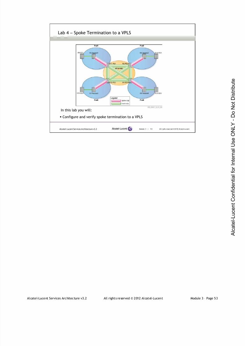
7/21/2019 Services Architecture v3.2 Student Guide Download
http://slidepdf.com/reader/full/services-architecture-v32-student-guide-download 228/429
Alcatel-Lucent Services Architecture v3.2 All rights reserved © 2012 Alcatel-Lucent Module 3 – Page 53
Module 3 | 53 A ll r ights re se rved ©2012 A lcatel -LucentAlcatel-Lucent Services Architecture v3.2
Lab 4 ― Spoke Termination to a VPLS
In this lab you will:
Configure and verify spoke termination to a VPLS

7/21/2019 Services Architecture v3.2 Student Guide Download
http://slidepdf.com/reader/full/services-architecture-v32-student-guide-download 229/429
Module 3 | 54 A ll r ights re se rved ©2012 A lcatel -LucentAlcatel-Lucent Services Architecture v3.2
www.alcatel-lucent.com/src
3FL-30636-AAAA-ZZZZA Edition 01

7/21/2019 Services Architecture v3.2 Student Guide Download
http://slidepdf.com/reader/full/services-architecture-v32-student-guide-download 230/429
7/21/2019 Services Architecture v3.2 Student Guide Download
http://slidepdf.com/reader/full/services-architecture-v32-student-guide-download 231/429
Alcatel-Lucent Services Architecture v3.2 All rights reserved © 2012 Alcatel-Lucent Module 4 – Page 2
Module 4 | 2 A ll r ights re se rved ©2012 Alcate l-LucentAlcatel-Lucent Services Architecture v3.2
Module Objectives
After successfully completing this module, you will be able to:
Use the correct operations, administration and maintenance
(OAM) tools to analyze, manage and troubleshoot IP/MPLS
service networks
Identify reasons to use mirroring service and differentiate
between local and distributed mirror service
Configure and verify the operation of a local and remote
mirror service
Alcatel-Lucent Services Archi tecture
This course is part of the Alcatel-Lucent Service Routing Certification (SRC) Program. Visit the Alcatel-
Lucent web site at www.alcatel-lucent.com/src for more information on the SRC program.
To locate additional information related to the topics presented in this manual, refer to the following:
Technical Practices for the specific product
Internet Standards documentation such as protocol standards bodies, RFCs and IETF drafts
Technical support pages of the Alcatel-Lucent web site located at http://www.alcatel-
lucent.com/support

7/21/2019 Services Architecture v3.2 Student Guide Download
http://slidepdf.com/reader/full/services-architecture-v32-student-guide-download 232/429
Alcatel-Lucent Services Architecture v3.2 All rights reserved © 2012 Alcatel-Lucent Module 4 – Page 3
Module 4 — OAM Tools and MirroringService
Section 1 — Operations, Administration and Maintenance (OAM)

7/21/2019 Services Architecture v3.2 Student Guide Download
http://slidepdf.com/reader/full/services-architecture-v32-student-guide-download 233/429
Alcatel-Lucent Services Architecture v3.2 All rights reserved © 2012 Alcatel-Lucent Module 4 – Page 4
Module 4 | 4 A ll r ights re se rved ©2012 Alcate l-LucentAlcatel-Lucent Services Architecture v3.2
Section Objectives
After successfully completing this section, you will be able to:
Provide an overview of OAM tools
Utilize the tools available for managing and troubleshooting a
service network ( lsp-ping, lsp-trace, SDP-ping, SDP-MTU, SVC-ping)
Complete Lab 5 – OAM tools

7/21/2019 Services Architecture v3.2 Student Guide Download
http://slidepdf.com/reader/full/services-architecture-v32-student-guide-download 234/429
Alcatel-Lucent Services Architecture v3.2 All rights reserved © 2012 Alcatel-Lucent Module 4 – Page 5
Module 4 | 5 A ll r ights re se rved ©2012 Alcate l-LucentAlcatel-Lucent Services Architecture v3.2
OAM Overview
Delivery of services requires a number of operations to occur
properly and at different levels in the service delivery model
A set of packet-based OAM tools are used to verify that a service isoperational
OAM diagnostics tools supplement the basic IP ping and traceroute
operations with diagnostics specialized for the different levels in the
service delivery model
OAM packets closely resemble customer packets to effectively test
the customer's forwarding path
OAM packets are kept within the service provider's network and are
not forwarded to the customer
Traditionally, ICMP ping has been commonly used to troubleshoot IP based networks. However, as an
MPLS core network has different behavior, ICMP ping will not be able to fully troubleshoot MPLS
networks. ICMP ping has some shortcomings, such as the inability to detect MPLS data plane failure if the
IP layer is working properly.
Proper delivery of services requires a number of operations to occur properly and at different levels in the
service delivery model. For example, operations such as the association of packets to a service, service
labels to a service and each service to a service tunnel must be performed properly in the forwarding
plane for the service to function properly. In order to verify that a service is operational, a set of in-band,
packet-based OAM tools is required, with the ability to test each of the individual packet operations.
For in-band testing, the OAM packets closely resemble customer packets to effectively test the customer's
forwarding path, but are distinguishable from customer packets so they are kept within the service
provider's network and not forwarded to the customer.
The 7750 SR OS suite of OAM diagnostics supplement the basic IP ping and traceroute operations with
diagnostics specialized for the different levels in the service delivery model. There are diagnostics for
MPLS LSPs, SDPs, Services and VPLS MACs within a service.

7/21/2019 Services Architecture v3.2 Student Guide Download
http://slidepdf.com/reader/full/services-architecture-v32-student-guide-download 235/429
Alcatel-Lucent Services Architecture v3.2 All rights reserved © 2012 Alcatel-Lucent Module 4 – Page 6
Module 4 | 6 A ll r ights re se rved ©2012 Alcate l-LucentAlcatel-Lucent Services Architecture v3.2
OAM Tools
OAM tools are useful in managing and troubleshooting a network
MPLS paths diagnostic tools:
lsp-ping and lsp-trace
SDP diagnostic tools:
sdp-ping and sdp-mtu
Service diagnostic tools:
svc-ping
Operations, administration and maintenance (OAM) tools available in modern routers are useful to
manage and troubleshoot the network.
The OAM tools that will be covered in this section are:
lsp-ping and lsp-trace - These allow the network operator to diagnose and discover the condition of
MPLS paths in the network.
sdp-ping and sdp-mtu - These allow the network operator to diagnose and discover details about a
configured SDP, including path MTU.
svc-ping - This tools allows the network operator to diagnose a configured service and the SDP bindings
for the service at both the local and remote ends.
lsp-ping and lsp-trace are defined in RFC 4379 and can inter-operate with other vendors’ equipment.
sdp-ping and svc-ping are tools proprietary to the Alcatel-Lucent 7750 SR.

7/21/2019 Services Architecture v3.2 Student Guide Download
http://slidepdf.com/reader/full/services-architecture-v32-student-guide-download 236/429
Alcatel-Lucent Services Architecture v3.2 All rights reserved © 2012 Alcatel-Lucent Module 4 – Page 7
Module 4 | 7 A ll r ights re se rved ©2012 Alcate l-LucentAlcatel-Lucent Services Architecture v3.2
Isp-ping and lsp-trace
Used on either LDP or RSVP-TE LSPs to verify the data path for the
LSP
Modeled after the ICMP echo request/reply used by ping andtraceroute to detect and localize faults in IP networks
A UDP packet is MPLS-encapsulated and transmitted along the LSP
LSP-ping verifies whether the packet reaches the egress label edge
router (LER) for a given FEC
For LSP traceroute, the packet is sent to the control plane of each
transit-label-switched router (LSR)
The 7750SR LSP diagnostics are implementations of LSP ping and LSP traceroute based on RFC
4379, Detecting Multi-Protocol Label Switched (MPLS) Data Plane Failures.
When an LSP fails to deliver user traffic, the failure cannot always be detected by the MPLS control plane.
For the MPLS data plane verification, the IP data plane verification tools (ping and traceroute) are
extended to work on the MPLS networks. The lsp Ping/traceroute, modeled after the ping/traceroute
paradigm: ping is used for connectivity verifications, and traceroute is used for hop-by-hop
fault localization and path tracing.
LSP ping and LSP traceroute provide diagnostics and troubleshooting capabilities for MPLS LSPs. These
tools provide basic building blocks for the MPLS OAM capabilities. This enables verification of the MPLS
data plane consistency.
The basic idea behind lsp-ping and lsp-trace tests is to verify that packets that belong to a particular
Forwarding Equivalence Class (FEC) actually end their MPLS path on a label switching router (LSR) that
is an egress for that FEC. These tests are carried out by sending a packet (OAM or MPLS echo request
packet) along the same data path as other packets belonging to this FEC. An MPLS echo request also
carries information about the FEC whose MPLS path is being verified. This echo request is forwarded just
like any other packet belonging to that FEC. In "ping" mode (basic connectivity check), the packet should
reach the end of the path, at which point it is sent to the control plane of the egress LSR, which then
verifies whether it is indeed an egress for the FEC. In traceroute mode (fault isolation), the packet is sent
to the control plane of each transit LSR, which performs various checks that it is indeed a transit LSR forthis path; this LSR also returns further information that helps check the control plane against the data
plane. For example, that the forwarding matches what the routing protocols determined as the path.

7/21/2019 Services Architecture v3.2 Student Guide Download
http://slidepdf.com/reader/full/services-architecture-v32-student-guide-download 237/429
Alcatel-Lucent Services Architecture v3.2 All rights reserved © 2012 Alcatel-Lucent Module 4 – Page 8
Module 4 | 8 A ll r ights re se rved ©2012 Alcate l-LucentAlcatel-Lucent Services Architecture v3.2
lsp-ping and lsp-trace Operation
The MPLS echo request packet is sent to a target router through the use of the appropriate label
stack associated with the LSP to be validated
The destination IP address of the MPLS echo request packet is defined as a 127. x .y .z /8 address
The 127. x .y .z /8 address prevents the IP packet from being IP switched to its destination if the LSPis broken
LSP-ping/traceroute uses the same label stack as is used by the LSP, which causes the echo to beswitched inband of LSP
An MPLS echo reply is sent in response to an MPLS echo request. The reply is sent as an IP packetand it may not take the same path used by the LSP
LSP-ping/traceroute only verifies the LSP paths in one direction; it does not verify the LSP return
path
LSP ping needs to diagnose situations where the control and data planes are out of sync. It performs this by routing
an MPLS echo request packet based solely on its label stack. That is, the IP destination address is never used in a
forwarding decision. In fact, the sender of an MPLS echo request packet may not know, a priori, the address of the
router at the end of the LSP.
The MPLS echo request packet is sent to a target router through the use of the appropriate label stack associated
with the LSP to be validated. Use of the label stack causes the packet to be forwarded over the LSP itself.
For the LSP ping/trace packet to be treated as a control packet, the same label stack is used as is used by the LSP,
which causes the echo to be switched in-band of the LSP tested. The destination of the echo request is a 127.x.y.z/8address and not the same as the one used for selecting the LSP.
Any router using the 127/8 address for forwarding (because of a broken LSP) punts the packet for local processing,
for example: the packet will not be forwarded naturally and is sent to the switch CPU for process switching. 127/8 also
forces the packet to be processed by the route processor (RP) at the egress router for a given LSP. The 127.x.y.z/8
address prevents the IP packet from being IP switched to its destination if the LSP is broken.
LSP Ping/traceroute uses the same label stack as is used by the LSP, which causes the echo to be switched in-band
of LSP.
An MPLS echo reply is sent in response to an MPLS echo request. The reply is sent as an IP packet and it is
forwarded using IP, MPLS, or a combination of both types of switching. The source address of the MPLS echo reply
packet is an address obtained from the router generating the echo reply. The destination address is the source
address of the router that originated the MPLS echo request packet.
An echo reply, which may or not be labeled, has the same outgoing interface IP address as the source. Thedestination IP address and port are copied from the source address and port of the echo request. The echo reply can
thus take an MPLS or an IP path to return to the source router. LSP Ping/Traceroute verifies only the LSP paths in
one direction and not the LSP return path.

7/21/2019 Services Architecture v3.2 Student Guide Download
http://slidepdf.com/reader/full/services-architecture-v32-student-guide-download 238/429
Alcatel-Lucent Services Architecture v3.2 All rights reserved © 2012 Alcatel-Lucent Module 4 – Page 9
Module 4 | 9 A ll r ights re se rved ©2012 Alcate l-LucentAlcatel-Lucent Services Architecture v3.2
lsp-ping and lsp-trace for LDP
*A:PE-3# oam lsp-ping prefix 10.10.10.4/32
LSP-PI NG 10. 10. 10. 4/32: 80 bytes MPLS payl oadSeq=1, send fr omintf to-PE1, repl y fr om10.10.10.4
udp- data- l en=32 tt l =255 rt t =1.81ms rc=3 (Egres sRtr )
- - - - LSP 10.10.10.4 /32 PINGStat i st i cs - - - -
1 packets sent, 1 packets received, 0.00%packet l ossround- tr i p mi n = 1.81ms, avg = 1.81ms, max = 1.81ms, st ddev = 0.000ms
*A:PE-3# oam lsp-trace prefix 10.10.10.4/32 detail
l sp-t race to 10. 10. 10. 4/32: 0 hops mi n, 0 hops max, 104 bytepackets
1 10.10. 10.1 r t t =1.11ms rc =8(DSRt rMat chLabel )DS 1: I f Addr 10.1. 2.2 MRU=1500 l abel=131066 proto=3( LDP)
2 10.10. 10.2 r t t =1.72ms rc =8(DSRt rMat chLabel )DS 1: I f Addr 10.2. 4.4 MRU=9198 l abel=131069 proto=3( LDP)
3 10.10. 10.4 r t t =1.73ms rc =3(Egress Rtr )
The figure shows the network topology used to demonstrate the use of lsp-ping and lsp-trace. The default
metric in this network is 100 and the link between PE3 and PE4 has been set to 1000 to force traffic on a
specific LSP. The default port MTU is 9212, but this has been set to 1514 on the link between PE1 and
PE2.
Notice that Maximum Receivable Unit (MRU) is the biggest packet size that a router can receive and
forward downstream without fragmentation.
LDP is configured on all router
*A:PE-3# show router ldp peer
===============================================================================
LDP Peer s
===============================================================================
Peer Adm Opr Hel l o Hol d KA KA Passi ve Aut o
Fact or Ti me Fact or Ti meout Mode Cr eated
- - - - - - - - - - - - - - - - - - - - - - - - - - - - - - - - - - - - - - - - - - - - - - - - - - - - - - - - - - - - - - - - - - - - - - - - - - - - - - -
10. 10. 10. 1 Up Up 3 45 4 40 Di sabl ed Yes
10. 10. 10. 2 Up Up 3 45 4 40 Di sabl ed Yes10. 10. 10. 4 Up Up 3 45 4 40 Di sabl ed Yes
- - - - - - - - - - - - - - - - - - - - - - - - - - - - - - - - - - - - - - - - - - - - - - - - - - - - - - - - - - - - - - - - - - - - - - - - - - - - - - -
No. of Peer s: 3

7/21/2019 Services Architecture v3.2 Student Guide Download
http://slidepdf.com/reader/full/services-architecture-v32-student-guide-download 239/429
Alcatel-Lucent Services Architecture v3.2 All rights reserved © 2012 Alcatel-Lucent Module 4 – Page 10
Module 4 | 10 A ll r ights re se rved ©2012 A lcatel -LucentAlcatel-Lucent Services Architecture v3.2
lsp-ping and lsp-trace for RSVP-TE LSP
*A:PE-3# oam lsp-ping "to-PE2"
LSP-PI NG to- PE2: 92 bytes MPLS payl oadSeq=1, send fr omintf to-PE1, repl y fr om10.10.10.2
udp- data- l en=32 tt l =255 rt t =1.84ms rc=3 (Egres sRtr )
- - - - LSP t o -PE2 PING Stat i s t i c s - - - -
1 packets sent, 1 packets received, 0.00%packet l ossround- tr i p mi n = 1.84ms, avg = 1.84ms, max = 1.84ms, st ddev = 0.000ms
*A:PE-3# oam lsp-trace "to-PE2" detail
l sp-tr ace to to-PE2: 0 hops mi n, 0 hops max, 116 byte packets1 10.10. 10.1 r t t =1.27ms rc =8(DSRt rMat chLabel )
DS 1: I f Addr 10.1. 2.2 MRU=1500 l abel=131063 proto=4( RSVP-TE)2 10.10. 10.2 r t t =1.70ms rc =3(Egress Rtr )
The use of lsp-ping and lsp-trace is similar for RSVP-TE, although the LSP is specified by name. An LSP
is configured from PE3 to PE2 using a loose path, since the metric value on the link between PE3 and
PE4 is high, the path for this LSP will be via PE1 as shown below:
*A:PE-3# show router mpls lsp "to-PE2" path detail
===============================================================================
…
LSP to- PE2 Pat h l oose
- - - - - - - - - - - - - - - - - - - - - - - - - - - - - - - - - - - - - - - - - - - - - - - - - - - - - - - - - - - - - - - - - - - - - - - - - - - - - - -
LSP Name : t o- PE2 Path LSP I D : 17922
From : 10. 10. 10. 3 To : 10. 10. 10. 2
Adm St at e : Up Oper St ate : Up
Pat h Name : l oose Pat h Type : Pr i mary
Pat h Admi n : Up Pat h Oper : Up
Out I nter f ace: 1/ 1/ 3 Out Label : 131066
…
Oper MTU : 1500 Neg MTU : 1500
Adapt i ve : Enabl ed Oper Metr i c : 200
…
Expl i ci t Hops:
No Hops Speci f i ed
Act ual Hops :
10. 1. 3. 3( 10. 10. 10. 3) Record Label : N/ A
- > 10. 1. 3. 1( 10. 10. 10. 1) Recor d Label : 131066
- > 10. 1. 2. 2( 10. 10. 10. 2) Recor d Label : 131063
Resi gEl i gi b*: Fal se
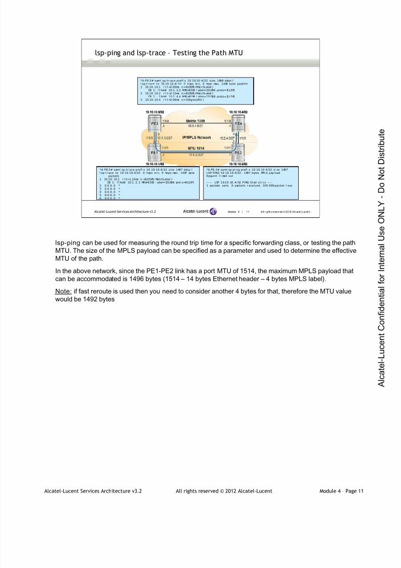
7/21/2019 Services Architecture v3.2 Student Guide Download
http://slidepdf.com/reader/full/services-architecture-v32-student-guide-download 240/429
Alcatel-Lucent Services Architecture v3.2 All rights reserved © 2012 Alcatel-Lucent Module 4 – Page 11
Module 4 | 11 A ll r ights re se rved ©2012 A lcatel -LucentAlcatel-Lucent Services Architecture v3.2
lsp-ping and lsp-trace – Testing the Path MTU
*A:PE-3# oaml sp-tr ace prefi x 10. 10.10.4/32 size 1496 detai ll sp-t race to 10.10.10.4/ 32: 0 hops mi n, 0 hops max, 1496 byte packets1 10.10. 10.1 r t t =2.00ms rc=8(DSRt rMat chLabel )
DS 1: I f Addr 10.1. 2.2 MRU=1500 l abel=131066 proto=3( LDP)2 10.10. 10.2 r t t =2.15ms rc=8(DSRt rMat chLabel )
DS 1: I f Addr 10.2. 4.4 MRU=9198 l abel=131069 proto=3( LDP)
3 10.10. 10.4 r t t =2.06ms rc=3(EgressRtr )
*A: PE-3# oaml sp-tr ace prefi x 10. 10. 10. 4/32 size 1497 detai ll sp-t race to 10. 10. 10. 4/32: 0 hops mi n, 0 hops max, 1497 byte
packets1 10.10. 10.1 r t t=1.24ms rc =8(DSRtr MatchLabel )
DS 1: I f Addr 10.1. 2. 2 MRU=1500 l abel=131066 prot o=3(LDP)2 0. 0.0. 0 *3 0. 0.0. 0 *4 0. 0.0. 0 *5 0. 0.0. 0 *
6 0. 0.0. 0 *
*A:PE-3# oaml sp-pi ng prefi x 10. 10. 10. 4/32 si ze 1497LSP- PING 10. 10. 10. 4/32: 1497 bytes MPLS payl oadRequest t i med out.
-- -- LSP 10.10.10.4/32 PING Stati sti cs -- --1 packets sent, 0 packets r eceived, 100. 00%packet l oss
lsp-ping can be used for measuring the round trip time for a specific forwarding class, or testing the path
MTU. The size of the MPLS payload can be specified as a parameter and used to determine the effective
MTU of the path.
In the above network, since the PE1-PE2 link has a port MTU of 1514, the maximum MPLS payload that
can be accommodated is 1496 bytes (1514 – 14 bytes Ethernet header – 4 bytes MPLS label).
Note: if fast reroute is used then you need to consider another 4 bytes for that, therefore the MTU value
would be 1492 bytes

7/21/2019 Services Architecture v3.2 Student Guide Download
http://slidepdf.com/reader/full/services-architecture-v32-student-guide-download 241/429
Alcatel-Lucent Services Architecture v3.2 All rights reserved © 2012 Alcatel-Lucent Module 4 – Page 12
Module 4 | 12 A ll r ights re se rved ©2012 A lcatel -LucentAlcatel-Lucent Services Architecture v3.2
SDP-ping and SDP-MTU
sdp-ping performs in-band unidirectional or round-trip connectivity
tests on SDPs
Unidirectional sdp-ping The remote SDP is not specified
Bi-directional sdp-ping
The remote SDP is specified
sdp-mtu enables the service provider to get the actual path MTU
supported between the service ingress and service termination
points
sdp-ping performs in-band unidirectional or round-trip connectivity tests on SDPs. The SDP ping OAM
packets are sent in-band in the tunnel encapsulation, so they will follow the same path as traffic within the
service. The SDP ping response can be received out-of-band in the control plane, or in-band using the
data plane for a round-trip test.
A Unidirectional test requires egress SDP ID and tests ability to reach the far-end IP address of the SDP
within the SDP encapsulation. A bi-directional test requires a local egress SDP ID and a remote SDP ID
and tests the remote SDP encapsulation.
The path MTU discovery tool provides a powerful tool that enables the service provider to get the exact
MTU supported between the service ingress and service termination points (accurate to one byte).
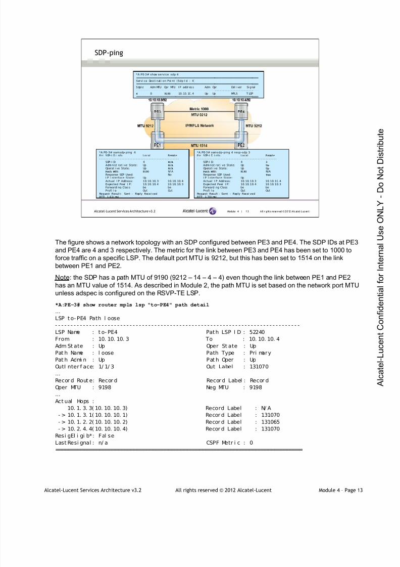
7/21/2019 Services Architecture v3.2 Student Guide Download
http://slidepdf.com/reader/full/services-architecture-v32-student-guide-download 242/429
Alcatel-Lucent Services Architecture v3.2 All rights reserved © 2012 Alcatel-Lucent Module 4 – Page 13
Module 4 | 13 A ll r ights re se rved ©2012 A lcatel -LucentAlcatel-Lucent Services Architecture v3.2
SDP-ping
*A:PE-3# show service sdp 4==============================================================================Servi ce Desti nati on Poi nt (Sdp I d : 4)==============================================================================SdpI d Adm MTU Opr MTU I P addr es s Adm Opr Del i ver Si gnal- - - - - - - - - - - - - - - - - - - - - - - - -- - - - - - - - - - - - - - - - - - - - - - - - -- - - - - - - - - - - - - - - - - - - - - - - -- - - -4 0 9190 10. 10. 10. 4 Up Up MPLS T LDP==============================================================================
*A:PE-3# oamsdp- ping 4Err SDP-I D I nfo Local Remote- - - - - - - - - - - - - - - - - - - - - - - - - - - - - - - - - - - - - - - - - - - - - - - - - -
SDP-I D: 4 N/A
Admi nist rat i ve State: Up N/A
Operat i ve State: Up N/A
Path MTU: 9190 N/ AResponse SDP Used: NoI P I nterface State: UpActual I P Address: 10. 10. 10. 3 10. 10. 10. 4Expected Peer I P: 10. 10. 10. 4 10. 10. 10. 3Forwardi ng Clas s be beProfi l e Out Out
Request Resul t: Sent - Reply Recei vedRTT: 1.61( ms)
*A:PE-3# oamsdp-ping 4 resp-sdp 3Err SDP-I D I nfo Local Remote- - - - - - - - - - - - - - - - - - - - - - - - - - - - - - - - - - - - - - - - - - - - - - - - - -
SDP-I D: 4 3
Admi nist rat i ve State: Up Up
Operat i ve State: Up Up
Path MTU: 9190 N/AResponse SDP Used: Yes
I P I nterface State: UpActual I P Address: 10. 10. 10. 3 10. 10. 10. 4Expected Peer I P: 10. 10. 10. 4 10. 10. 10. 3Forwardi ng Class be beProfi l e Out Out
Request Result : Sent - Reply Recei vedRTT: 1.70( ms)
The figure shows a network topology with an SDP configured between PE3 and PE4. The SDP IDs at PE3
and PE4 are 4 and 3 respectively. The metric for the link between PE3 and PE4 has been set to 1000 to
force traffic on a specific LSP. The default port MTU is 9212, but this has been set to 1514 on the link
between PE1 and PE2.
Note: the SDP has a path MTU of 9190 (9212 – 14 – 4 – 4) even though the link between PE1 and PE2
has an MTU value of 1514. As described in Module 2, the path MTU is set based on the network port MTU
unless adspec is configured on the RSVP-TE LSP.
*A:PE-3# show router mpls lsp "to-PE4" path detail
…
LSP t o- PE4 Path l oose
- - - - - - - - - - - - - - - - - - - - - - - - - - - - - - - - - - - - - - - - - - - - - - - - - - - - - - - - - - - - - - - - - - - - - - - - - - - - - - -
LSP Name : t o- PE4 Path LSP I D : 52240
From : 10. 10. 10. 3 To : 10. 10. 10. 4
Adm St ate : Up Oper St ate : Up
Pat h Name : l oose Path Type : Pri mary
Pat h Admi n : Up Pat h Oper : Up
OutI nter f ace: 1/ 1/ 3 Out Label : 131070
…
Recor d Rout e: Recor d Recor d Label : Recor d
Oper MTU : 9198 Neg MTU : 9198
…
Act ual Hops :
10. 1. 3. 3( 10. 10. 10. 3) Record Label : N/ A
- > 10. 1. 3. 1( 10. 10. 10. 1) Recor d Label : 131070
- > 10. 1. 2. 2( 10. 10. 10. 2) Recor d Label : 131065
- > 10. 2. 4. 4( 10. 10. 10. 4) Recor d Label : 131070
Resi gEl i gi b*: Fal se
Last Resi gnal : n/ a CSPF Metr i c : 0
===============================================================================
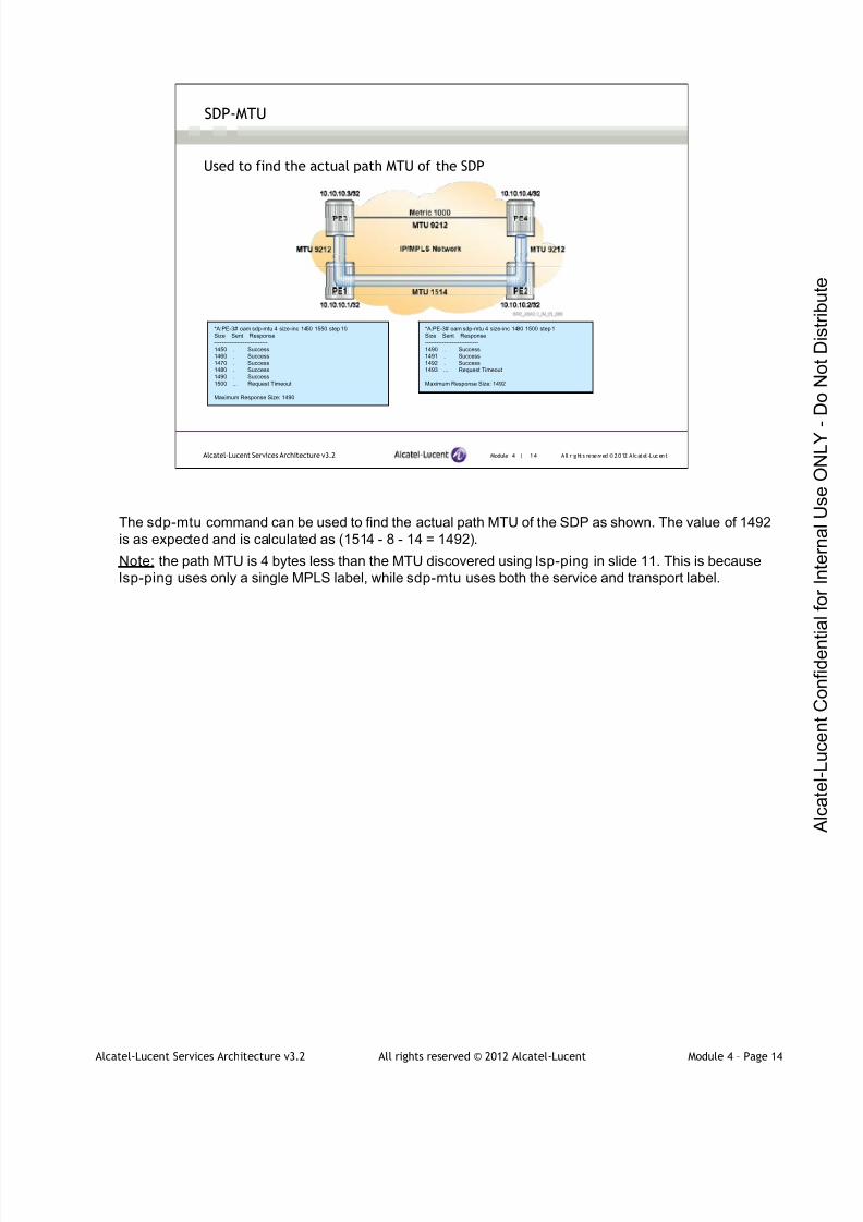
7/21/2019 Services Architecture v3.2 Student Guide Download
http://slidepdf.com/reader/full/services-architecture-v32-student-guide-download 243/429
Alcatel-Lucent Services Architecture v3.2 All rights reserved © 2012 Alcatel-Lucent Module 4 – Page 14
Module 4 | 14 A ll r ights re se rved ©2012 A lcatel -LucentAlcatel-Lucent Services Architecture v3.2
SDP-MTU
*A:PE-3# oam sdp-mtu 4 size-inc 1450 1550 step 10
Size Sent Response
----------------------------
1450 . Success
1460 . Success
1470 . Success
1480 . Success
1490 . Success
1500 ... Request Timeout
Maximum Response Size: 1490
*A:PE-3# oam sdp-mtu 4 size-inc 1490 1500 step 1
Size Sent Response
----------------------------
1490 . Success
1491 . Success
1492 . Success
1493 ... Request Timeout
Maximum Response Size: 1492
Used to find the actual path MTU of the SDP
The sdp-mtu command can be used to find the actual path MTU of the SDP as shown. The value of 1492
is as expected and is calculated as (1514 - 8 - 14 = 1492).
Note: the path MTU is 4 bytes less than the MTU discovered using lsp-ping in slide 11. This is because
lsp-ping uses only a single MPLS label, while sdp-mtu uses both the service and transport label.

7/21/2019 Services Architecture v3.2 Student Guide Download
http://slidepdf.com/reader/full/services-architecture-v32-student-guide-download 244/429
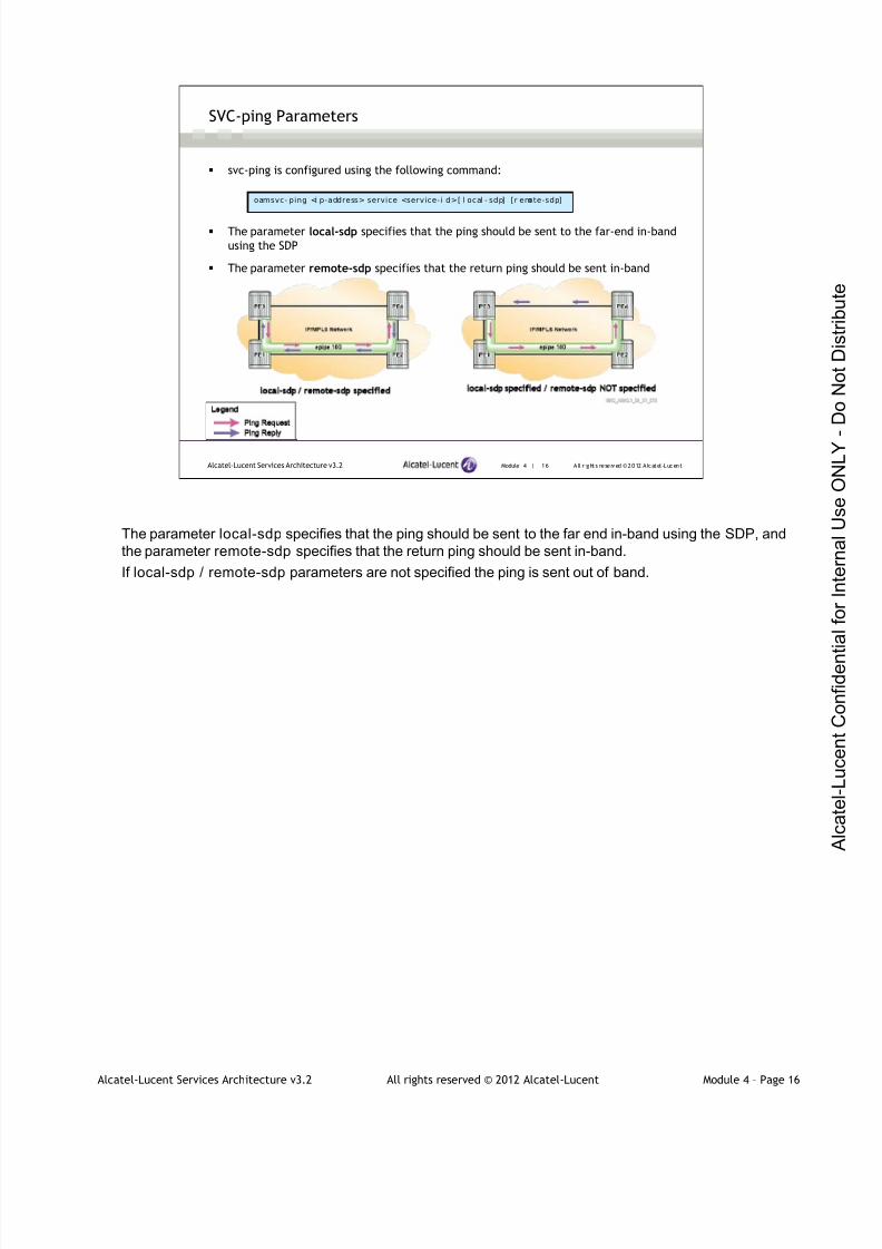
7/21/2019 Services Architecture v3.2 Student Guide Download
http://slidepdf.com/reader/full/services-architecture-v32-student-guide-download 245/429
Alcatel-Lucent Services Architecture v3.2 All rights reserved © 2012 Alcatel-Lucent Module 4 – Page 16
Module 4 | 16 A ll r ights re se rved ©2012 A lcatel -LucentAlcatel-Lucent Services Architecture v3.2
SVC-ping Parameters
oamsvc- ping <i p-address> service <service-i d>[ l ocal - sdp] [r emote-sdp]
svc-ping is configured using the following command:
The parameter local-sdp specifies that the ping should be sent to the far-end in-band
using the SDP
The parameter remote-sdp specifies that the return ping should be sent in-band
The parameter local-sdp specifies that the ping should be sent to the far end in-band using the SDP, and
the parameter remote-sdp specifies that the return ping should be sent in-band.
If local-sdp / remote-sdp parameters are not specified the ping is sent out of band.
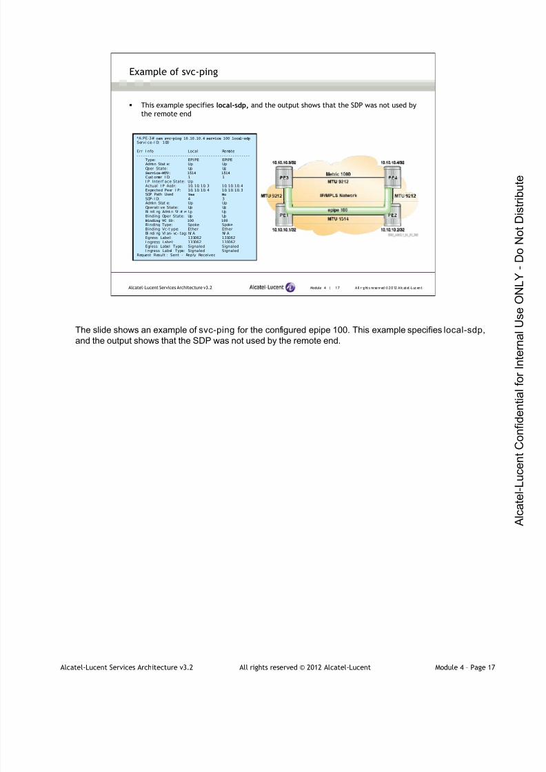
7/21/2019 Services Architecture v3.2 Student Guide Download
http://slidepdf.com/reader/full/services-architecture-v32-student-guide-download 246/429
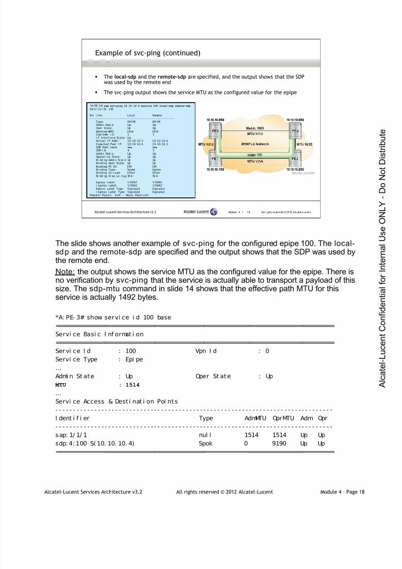
7/21/2019 Services Architecture v3.2 Student Guide Download
http://slidepdf.com/reader/full/services-architecture-v32-student-guide-download 247/429
Alcatel-Lucent Services Architecture v3.2 All rights reserved © 2012 Alcatel-Lucent Module 4 – Page 18
Module 4 | 18 A ll r ights re se rved ©2012 A lcatel -LucentAlcatel-Lucent Services Architecture v3.2
Example of svc-ping (continued)
*A:PE-3# oam svc-ping 10.10.10.4 service 100 local-sdp remote-sdp
Servi ce-I D: 100
Err I nfo Local Remote- - - - - - - - - - - - - - - - - - - - - - - - - - - - - - - - - - - - - - - - - - - - - - - - - - - - -
Type: EPI PE EPI PEAdmi n Stat e: Up UpOper State: Up UpService-MTU: 1514 1514
Cust omer I D: 1 1I P Interf ace State: UpActual I P Addr: 10. 10. 10. 3 10. 10. 10. 4Expected Peer I P: 10. 10. 10. 4 10. 10. 10. 3SDP Path Used: Yes Yes
SDP-I D: 4 3Admi n Stat e: Up UpOperat i ve State: Up UpBi ndi ng Admi n Stat e: Up UpBinding Oper State: Up UpBinding VC ID: 100 100
Bi nding Type: Spoke SpokeBinding Vc-t ype: Ether EtherBi ndi ng Vl an- vc- tag: N/ A N/ A
Egress Label: 131062 131062I ngress Label: 131062 131062Egress Label Type: Signaled SignaledI ngress Label Type: Signaled Signaled
Request Resul t: Sent - Reply Recei ved
The local-sdp and the remote-sdp are specified, and the output shows that the SDPwas used by the remote end
The svc-ping output shows the service MTU as the configured value for the epipe
The slide shows another example of svc-ping for the configured epipe 100. The local-sdp and the remote-sdp are specified and the output shows that the SDP was used bythe remote end.
Note: the output shows the service MTU as the configured value for the epipe. There isno verification by svc-ping that the service is actually able to transport a payload of thissize. The sdp-mtu command in slide 14 shows that the effective path MTU for this
service is actually 1492 bytes.
*A: PE- 3# show servi ce i d 100 base
===============================================================================
Servi ce Basi c I nf ormat i on
===============================================================================
Ser vi ce I d : 100 Vpn I d : 0
Servi ce Type : Epi pe
…
Admi n St ate : Up Oper St ate : Up
MTU : 1514
…
Servi ce Access & Dest i nat i on Poi nts
- - - - - - - - - - - - - - - - - - - - - - - - - - - - - - - - - - - - - - - - - - - - - - - - - - - - - - - - - - - - - - - - - - - - - - - - - - - - - - -
I dent i f i er Type AdmMTU OprMTU Adm Opr
- - - - - - - - - - - - - - - - - - - - - - - - - - - - - - - - - - - - - - - - - - - - - - - - - - - - - - - - - - - - - - - - - - - - - - - - - - - - - - -
sap: 1/ 1/ 1 nul l 1514 1514 Up Up
sdp: 4: 100 S( 10. 10. 10. 4) Spok 0 9190 Up Up
===============================================================================
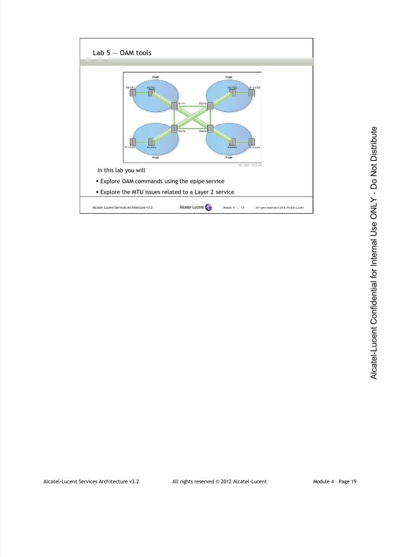
7/21/2019 Services Architecture v3.2 Student Guide Download
http://slidepdf.com/reader/full/services-architecture-v32-student-guide-download 248/429
Alcatel-Lucent Services Architecture v3.2 All rights reserved © 2012 Alcatel-Lucent Module 4 – Page 19
Module 4 | 19 A ll r ights re se rved ©2012 A lcatel -LucentAlcatel-Lucent Services Architecture v3.2
Lab 5 ― OAM tools
In this lab you will
Explore OAM commands using the epipe service
Explore the MTU issues related to a Layer 2 service

7/21/2019 Services Architecture v3.2 Student Guide Download
http://slidepdf.com/reader/full/services-architecture-v32-student-guide-download 249/429
Alcatel-Lucent Services Architecture v3.2 All rights reserved © 2012 Alcatel-Lucent Module 4 – Page 20
Module 4 — OAM Tools and MirroringService
Section 2 — Mirroring Service
7/21/2019 Services Architecture v3.2 Student Guide Download
http://slidepdf.com/reader/full/services-architecture-v32-student-guide-download 250/429
Alcatel-Lucent Services Architecture v3.2 All rights reserved © 2012 Alcatel-Lucent Module 4 – Page 21
Module 4 | 21 A ll r ights re se rved ©2012 A lcatel -LucentAlcatel-Lucent Services Architecture v3.2
Section Objectives
After successfully completing this section, you will be able to:
Describe mirroring service
Differentiate between local and distributed mirror service
Configure and verify the operation of a local and remote mirror
service
Complete Lab 6 – Mirror Service
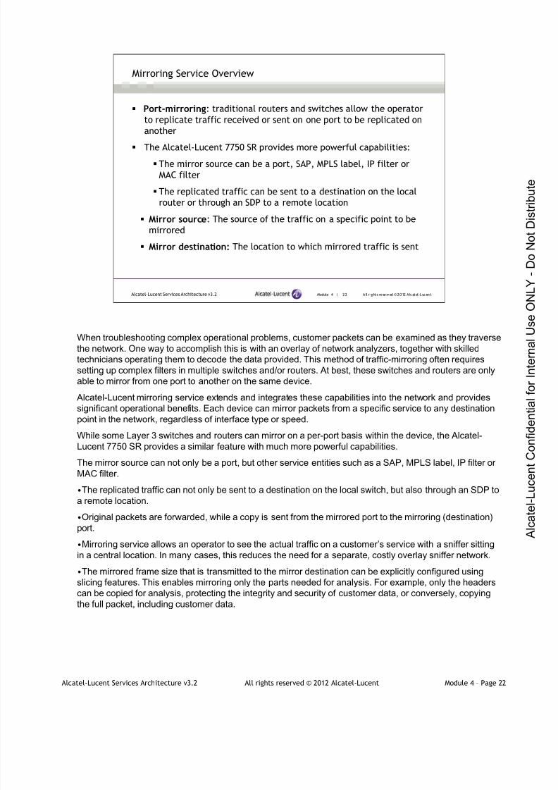
7/21/2019 Services Architecture v3.2 Student Guide Download
http://slidepdf.com/reader/full/services-architecture-v32-student-guide-download 251/429
Alcatel-Lucent Services Architecture v3.2 All rights reserved © 2012 Alcatel-Lucent Module 4 – Page 22
Module 4 | 22 A ll r ights re se rved ©2012 A lcatel -LucentAlcatel-Lucent Services Architecture v3.2
Mirroring Service Overview
Port-mirroring: traditional routers and switches allow the operator
to replicate traffic received or sent on one port to be replicated on
another
The Alcatel-Lucent 7750 SR provides more powerful capabilities:
The mirror source can be a port, SAP, MPLS label, IP filter or
MAC filter
The replicated traffic can be sent to a destination on the local
router or through an SDP to a remote location
Mirror source: The source of the traffic on a specific point to be
mirrored
Mirror destination: The location to which mirrored traffic is sent
When troubleshooting complex operational problems, customer packets can be examined as they traverse
the network. One way to accomplish this is with an overlay of network analyzers, together with skilled
technicians operating them to decode the data provided. This method of traffic-mirroring often requires
setting up complex filters in multiple switches and/or routers. At best, these switches and routers are only
able to mirror from one port to another on the same device.
Alcatel-Lucent mirroring service extends and integrates these capabilities into the network and provides
significant operational benefits. Each device can mirror packets from a specific service to any destination
point in the network, regardless of interface type or speed.
While some Layer 3 switches and routers can mirror on a per-port basis within the device, the Alcatel-
Lucent 7750 SR provides a similar feature with much more powerful capabilities.
The mirror source can not only be a port, but other service entities such as a SAP, MPLS label, IP filter or
MAC filter.
•The replicated traffic can not only be sent to a destination on the local switch, but also through an SDP to
a remote location.
•Original packets are forwarded, while a copy is sent from the mirrored port to the mirroring (destination)
port.
•Mirroring service allows an operator to see the actual traffic on a customer’s service with a sniffer sitting
in a central location. In many cases, this reduces the need for a separate, costly overlay sniffer network.
•The mirrored frame size that is transmitted to the mirror destination can be explicitly configured using
slicing features. This enables mirroring only the parts needed for analysis. For example, only the headers
can be copied for analysis, protecting the integrity and security of customer data, or conversely, copying
the full packet, including customer data.
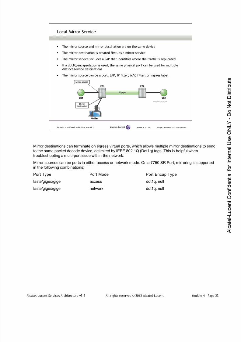
7/21/2019 Services Architecture v3.2 Student Guide Download
http://slidepdf.com/reader/full/services-architecture-v32-student-guide-download 252/429
Alcatel-Lucent Services Architecture v3.2 All rights reserved © 2012 Alcatel-Lucent Module 4 – Page 23
Module 4 | 23 A ll r ights re se rved ©2012 A lcatel -LucentAlcatel-Lucent Services Architecture v3.2
Local Mirror Service
The mirror source and mirror destination are on the same device
The mirror destination is created first, as a mirror service
The mirror service includes a SAP that identifies where the traffic is replicated
If a dot1Q encapsulation is used, the same physical port can be used for multiple
distinct service destinations
The mirror source can be a port, SAP, IP filter, MAC filter, or ingress label
Mirror destinations can terminate on egress virtual ports, which allows multiple mirror destinations to send
to the same packet decode device, delimited by IEEE 802.1Q (Dot1q) tags. This is helpful when
troubleshooting a multi-port issue within the network.
Mirror sources can be ports in either access or network mode. On a 7750 SR Port, mirroring is supported
in the following combinations:
Port Type Port Mode Port Encap Type
faste/gige/xgige access dot1q, null
faste/gige/xgige network dot1q, null
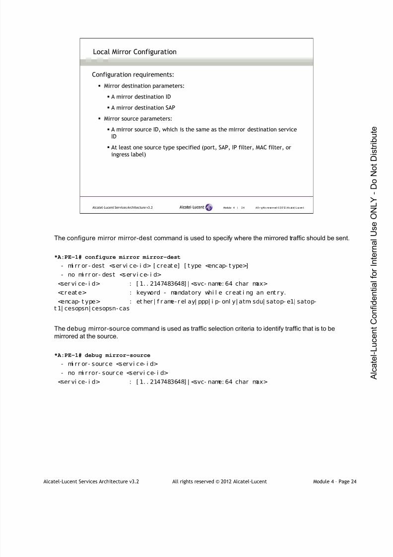
7/21/2019 Services Architecture v3.2 Student Guide Download
http://slidepdf.com/reader/full/services-architecture-v32-student-guide-download 253/429
Alcatel-Lucent Services Architecture v3.2 All rights reserved © 2012 Alcatel-Lucent Module 4 – Page 24
Module 4 | 24 A ll r ights re se rved ©2012 A lcatel -LucentAlcatel-Lucent Services Architecture v3.2
Local Mirror Configuration
Configuration requirements:
Mirror destination parameters:
A mirror destination ID
A mirror destination SAP
Mirror source parameters:
A mirror source ID, which is the same as the mirror destination service
ID
At least one source type specified (port, SAP, IP filter, MAC filter, or
ingress label)
The configure mirror mirror-dest command is used to specify where the mirrored traffic should be sent.
*A:PE-1# configure mirror mirror-dest
- mi rr or - dest <ser vi ce- i d> [ creat e] [ t ype <encap- t ype>]
- no mi rr or - dest <serv i ce- i d>
<ser vi ce- i d> : [ 1. . 2147483648] | <svc- name: 64 char max>
<cr eat e> : keyword - mandatory whi l e cr eat i ng an ent r y.<encap- t ype> : et her | f r ame- r el ay| ppp| i p- onl y| atm- sdu| satop- e1| satop-
t 1| cesopsn| cesopsn- cas
The debug mirror-source command is used as traffic selection criteria to identify traffic that is to be
mirrored at the source.
*A:PE-1# debug mirror-source
- mi rr or- source <servi ce- i d>
- no mi r ror- sour ce <servi ce- i d>
<ser vi ce- i d> : [ 1. . 2147483648] | <svc- name: 64 char max>
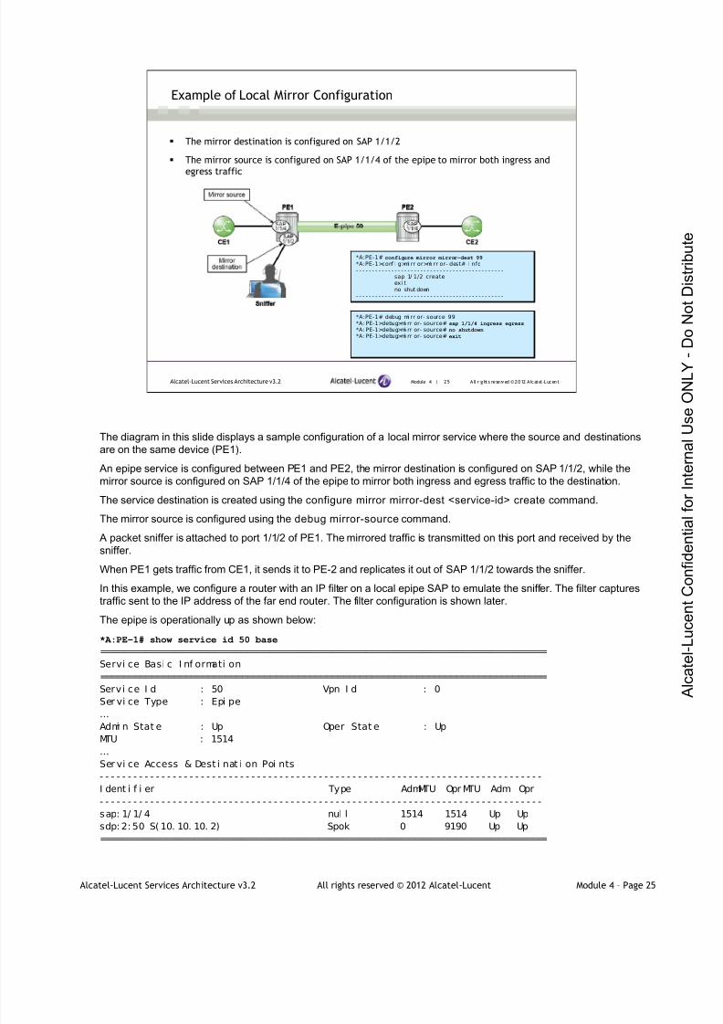
7/21/2019 Services Architecture v3.2 Student Guide Download
http://slidepdf.com/reader/full/services-architecture-v32-student-guide-download 254/429
Alcatel-Lucent Services Architecture v3.2 All rights reserved © 2012 Alcatel-Lucent Module 4 – Page 25
Module 4 | 25 A ll r ights re se rved ©2012 A lcatel -LucentAlcatel-Lucent Services Architecture v3.2
Example of Local Mirror Configuration
The mirror destination is configured on SAP 1/1/2
The mirror source is configured on SAP 1/1/4 of the epipe to mirror both ingress and
egress traffic
*A:PE-1# configure mirror mirror-dest 99
*A:PE-1>conf i g>mi rr or>mi rr or- dest# i nfo- - - - - - - - - - - - - - - - - - - - - - - - - - - - - - - - - - - - - - - - - - - - - -
sap 1/ 1/2 createex i tno shut down
- - - - - - - - - - - - - - - - - - - - - - - - - - - - - - - - - - - - - - - - - - - - - -
*A:PE-1# debug mi rr or- source 99*A: PE-1>debug>mi rr or- source# sap 1/1/4 ingress egress
*A: PE-1>debug>mi rr or- source# no shutdown
*A: PE-1>debug>mi rr or- source# exit
The diagram in this slide displays a sample configuration of a local mirror service where the source and destinations
are on the same device (PE1).
An epipe service is configured between PE1 and PE2, the mirror destination is configured on SAP 1/1/2, while the
mirror source is configured on SAP 1/1/4 of the epipe to mirror both ingress and egress traffic to the destination.
The service destination is created using the configure mirror mirror-dest <service-id> create command.
The mirror source is configured using the debug mirror-source command.
A packet sniffer is attached to port 1/1/2 of PE1. The mirrored traffic is transmitted on this port and received by thesniffer.
When PE1 gets traffic from CE1, it sends it to PE-2 and replicates it out of SAP 1/1/2 towards the sniffer.
In this example, we configure a router with an IP filter on a local epipe SAP to emulate the sniffer. The filter captures
traffic sent to the IP address of the far end router. The filter configuration is shown later.
The epipe is operationally up as shown below:
*A:PE-1# show service id 50 base
===============================================================================
Servi ce Basi c I nf ormati on
===============================================================================
Servi ce I d : 50 Vpn I d : 0
Ser vi ce Type : Epi pe
…Admi n Stat e : Up Oper Stat e : Up
MTU : 1514
…
Ser vi ce Access & Dest i nat i on Poi nts
- - - - - - - - - - - - - - - - - - - - - - - - - - - - - - - - - - - - - - - - - - - - - - - - - - - - - - - - - - - - - - - - - - - - - - - - - - - - - - -
I dent i f i er Type AdmMTU Opr MTU Adm Opr
- - - - - - - - - - - - - - - - - - - - - - - - - - - - - - - - - - - - - - - - - - - - - - - - - - - - - - - - - - - - - - - - - - - - - - - - - - - - - - -
sap: 1/ 1/ 4 nul l 1514 1514 Up Up
sdp: 2: 50 S( 10. 10. 10. 2) Spok 0 9190 Up Up
===============================================================================

7/21/2019 Services Architecture v3.2 Student Guide Download
http://slidepdf.com/reader/full/services-architecture-v32-student-guide-download 255/429
Alcatel-Lucent Services Architecture v3.2 All rights reserved © 2012 Alcatel-Lucent Module 4 – Page 26
Module 4 | 26 A ll r ights re se rved ©2012 A lcatel -LucentAlcatel-Lucent Services Architecture v3.2
Example of Local Mirror Configuration (continued)
The mirror service can be verified using the following commands:
*A:PE-1# show service service-using mirror
===============================================================================Servi ces [mi rr or]===============================================================================ServiceId Type Adm Opr CustomerId Service Name- - - - - - - - - - - - - - - - - - - - - - - -- - - - - - - - - - - - - - - - - - - - - - - -- - - - - - - - - - - - - - - - - - - - - - - - -- - - - - -99 Mi rror Up Up 1- - - - - - - - - - - - - - - - - - - - - - - -- - - - - - - - - - - - - - - - - - - - - - - -- - - - - - - - - - - - - - - - - - - - - - - - -- - - - - -Matchi ng Services : 1- - - - - - - - - - - - - - - - - - - - - - - -- - - - - - - - - - - - - - - - - - - - - - - -- - - - - - - - - - - - - - - - - - - - - - - - -- - - - - -
*A:PE-1# show mirror mirror-dest
===============================================================================Mi rror Servi ces===============================================================================Id Type Adm Opr Des t i nat i o n SDP Lbl / Sl i c e
SAP QoS- - - - - - - - - - - - - - - - - - - - - - - -- - - - - - - - - - - - - - - - - - - - - - - -- - - - - - - - - - - - - - - - - - - - - - - - -- - - - - -99 Ether Up Up SAP 1/1/2 1 0===============================================================================
A mirror source can only have one destination.
If a mirrored destination service ID is shut down, the corresponding mirror source is put into an operational
down mode.
The default state for a mirror destination is shutdown, while the default state for a mirror source is no-
shutdown.

7/21/2019 Services Architecture v3.2 Student Guide Download
http://slidepdf.com/reader/full/services-architecture-v32-student-guide-download 256/429
Alcatel-Lucent Services Architecture v3.2 All rights reserved © 2012 Alcatel-Lucent Module 4 – Page 27
Module 4 | 27 A ll r ights re se rved ©2012 A lcatel -LucentAlcatel-Lucent Services Architecture v3.2
Example of Local Mirror Configuration (continued)
Creating a sniffer using IP filter on an epipe SAP configuration
*A:Snif f er>conf i g>servi ce>epi pe#i nfo- - - - - - - - - - - - - - - - - - - - - - - - - - - - - - - - - - - - -
sap 1/1/ 1 createexi tsap 1/1/ 2 create
i ngressf i l t er i p 11
exi texi tno shut down
- - - - - - - - - - - - - - - - - - - - - - - - - - - - - - - - - - - - - -
*A:Sni ff er>config>fi l ter# i nfo- - - - - - - - - - - - - - - - - - - - - - - - - - - - - - - - - - - - - - - - -
l og 111 createdesti nati on memory 100
exi ti p-f i l ter 11 create
entry 10 createmat ch
dst-i p 192.168.1.0/27exi tl og 111acti on f orward
exitexi t
- - - - - - - - - - - - - - - - - - - - - - - - - - - - - - - - - - - - - - - - -
In this example, we are not using a conventional PC to function as a sniffer, instead we are configuring an
IP filter to replace the PC and act as a sniffer.
When the packets arrive at SAP 1/1/4 on PE1, they will be replicated to SAP 1/1/2. To examine these
packets, we need a network protocol analyzer or sniffer.
The slide shows the configuration of an IP filter on a local epipe 110 that is configured on the sniffer router.
The filter is configured to capture traffic sent to destination 192.168.1.0/27, forward it through the local
epipe 110, and log this information and store it the memory. The filter is applied at SAP 1/1/2 for the
ingress traffic.
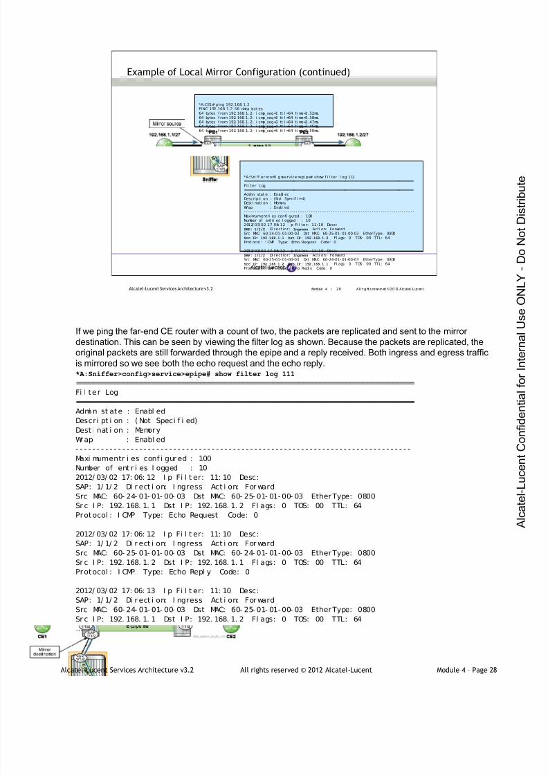
7/21/2019 Services Architecture v3.2 Student Guide Download
http://slidepdf.com/reader/full/services-architecture-v32-student-guide-download 257/429
Alcatel-Lucent Services Architecture v3.2 All rights reserved © 2012 Alcatel-Lucent Module 4 – Page 28
Module 4 | 28 A ll r ights re se rved ©2012 A lcatel -LucentAlcatel-Lucent Services Architecture v3.2
Example of Local Mirror Configuration (continued)
*A:CE1# ping 192.168. 1.2PING 192.168. 1.2 56 data byt es64 bytes f rom 192. 168. 1. 2: i cmp_seq=1 tt l =64 ti me=2. 52ms.64 bytes f rom 192. 168. 1. 2: i cmp_seq=2 tt l =64 ti me=2. 58ms.64 bytes f rom 192. 168. 1. 2: i cmp_seq=3 tt l =64 ti me=2. 47ms.64 bytes f rom 192. 168. 1. 2: i cmp_seq=4 tt l =64 ti me=2. 45ms.64 bytes f rom 192. 168. 1. 2: i cmp_seq=5 tt l =64 ti me=2. 50ms.
*A:Sni ff er>confi g>service>epi pe# show f i l ter l og 111===============================================================================Fil ter Log===============================================================================Admi n stat e : Enabl edDescripti on : (Not Specif i ed)Dest i nati on : MemoryWr ap : Enabl ed- - - - - - - - - - - - - - - - - - - - - - -- - - - - - - - - - - - - - - - - - - - - - - -- - - - - - - - - - - - - - - - - - - - - - - - -- - - - - - -Maximumentri es confi gured : 100Number of ent ri es l ogged : 102012/ 03/ 02 17: 06: 12 I p Fil ter: 11:10 Desc:SAP: 1/1/2 Di rection: Ingress Acti on: ForwardSrc MAC: 60-24-01- 01-00-03 Dst MAC: 60-25-01- 01-00-03 EtherType: 0800Src IP: 192.168.1.1 Dst IP: 192.168.1.2 Fl ags: 0 TOS: 00 TTL: 64Prot ocol : I CMP Type: Echo Request Code: 0
2012/ 03/ 02 17: 06: 12 I p Fil ter: 11:10 Desc:SAP: 1/1/2 Di rection: Ingress Acti on: ForwardSrc MAC: 60-25-01- 01-00-03 Dst MAC: 60-24-01- 01-00-03 EtherType: 0800Src IP: 192.168.1.2 Dst IP: 192.168.1.1 Fl ags: 0 TOS: 00 TTL: 64Prot ocol : I CMP Type: Echo Repl y Code: 0
If we ping the far-end CE router with a count of two, the packets are replicated and sent to the mirror
destination. This can be seen by viewing the filter log as shown. Because the packets are replicated, the
original packets are still forwarded through the epipe and a reply received. Both ingress and egress traffic
is mirrored so we see both the echo request and the echo reply.*A:Sniffer>config>service>epipe# show filter log 111
===============================================================================
Fi l ter Log
===============================================================================
Admi n st ate : Enabl ed
Descri pt i on : ( Not Speci f i ed)
Dest i nat i on : Memory
Wr ap : Enabl ed
- - - - - - - - - - - - - - - - - - - - - - - - - - - - - - - - - - - - - - - - - - - - - - - - - - - - - - - - - - - - - - - - - - - - - - - - - - - - - - -
Maxi mumentr i es conf i gur ed : 100
Number of ent r i es l ogged : 10
2012/ 03/ 02 17: 06: 12 I p Fi l t er: 11: 10 Desc:
SAP: 1/ 1/ 2 Di r ect i on: I ngress Act i on: For ward
Src MAC: 60- 24- 01- 01- 00- 03 Dst MAC: 60- 25- 01- 01-00- 03 EtherType: 0800
Sr c I P: 192. 168. 1. 1 Dst I P: 192. 168. 1. 2 Fl ags: 0 TOS: 00 TTL: 64
Protocol : I CMP Type: Echo Request Code: 0
2012/ 03/ 02 17: 06: 12 I p Fi l t er: 11: 10 Desc:
SAP: 1/ 1/ 2 Di r ect i on: I ngress Act i on: For wardSrc MAC: 60- 25- 01- 01- 00- 03 Dst MAC: 60- 24- 01- 01-00- 03 EtherType: 0800
Sr c I P: 192. 168. 1. 2 Dst I P: 192. 168. 1. 1 Fl ags: 0 TOS: 00 TTL: 64
Protocol : I CMP Type: Echo Repl y Code: 0
2012/ 03/ 02 17: 06: 13 I p Fi l t er: 11: 10 Desc:
SAP: 1/ 1/ 2 Di r ect i on: I ngress Act i on: For ward
Src MAC: 60- 24- 01- 01- 00- 03 Dst MAC: 60- 25- 01- 01-00- 03 EtherType: 0800
Sr c I P: 192. 168. 1. 1 Dst I P: 192. 168. 1. 2 Fl ags: 0 TOS: 00 TTL: 64
…

7/21/2019 Services Architecture v3.2 Student Guide Download
http://slidepdf.com/reader/full/services-architecture-v32-student-guide-download 258/429
Alcatel-Lucent Services Architecture v3.2 All rights reserved © 2012 Alcatel-Lucent Module 4 – Page 29
Module 4 | 29 A ll r ights re se rved ©2012 A lcatel -LucentAlcatel-Lucent Services Architecture v3.2
Remote Mirror Service
Mirror source and mirror destination are on different routers
The mirror source and mirror destination parameters must be configured using the
same mirror service ID
The router with the mirror source (PE2) has an SDP as the mirror destination
The mirrored traffic is encapsulated and sent to the far-end router (PE1)
The far-end router has a local mirror destination defined that accepts the packets
from the remote source
Remote mirroring uses a service distribution path (SDP), which acts as a logical way of directing traffic
from one 7750 SR (PE2) to another (PE1) through a unidirectional service tunnel. The SDP terminates at
the far-end 7750 SR (PE1), which directs packets to the correct destination on that device.
The SDP configuration from the mirrored device to a far-end 7750SR requires a return-path SDP from the
far-end 7750 SR (PE1) back to the mirrored router (PE2). Each device must have an SDP defined for
every remote router to which it wants to provide mirroring services. SDPs must be created before services
can be configured.

7/21/2019 Services Architecture v3.2 Student Guide Download
http://slidepdf.com/reader/full/services-architecture-v32-student-guide-download 259/429
Alcatel-Lucent Services Architecture v3.2 All rights reserved © 2012 Alcatel-Lucent Module 4 – Page 30
Module 4 | 30 A ll r ights re se rved ©2012 A lcatel -LucentAlcatel-Lucent Services Architecture v3.2
Remote Mirror Service Configuration
Configuration requirements:
Mirror destination parameters:
A mirror destination ID, which is the same as the mirror source serviceID
The remote source needs to be specified in the mirror destination
service
A mirror destination SAP or SDP
Mirror source parameters:
A mirror source ID, which is the same as the mirror destination service
ID
An SDP as the mirror destination
At least one source type specified (port, SAP, IP filter, MAC filter, or
ingress label)

7/21/2019 Services Architecture v3.2 Student Guide Download
http://slidepdf.com/reader/full/services-architecture-v32-student-guide-download 260/429
Alcatel-Lucent Services Architecture v3.2 All rights reserved © 2012 Alcatel-Lucent Module 4 – Page 31
Module 4 | 31 A ll r ights re se rved ©2012 A lcatel -LucentAlcatel-Lucent Services Architecture v3.2
Example of Remote Mirror Configuration – Mirror Source
An SDP is specified as the mirror destination
The mirror source is configured on SAP 1/1/4 to mirror both ingress and egress traffic
*A:PE-2# confi gure mi rror mi rror- dest 999 create*A:PE-2>conf i g>mi rr or>mi rr or- dest $ spoke-sdp 1:999 create*A: PE-2>confi g>mi rr or>mi rr or- dest>spoke-s dp$ back*A: PE-2>confi g>mi rr or>mi rr or- dest# no shutdown*A:PE-2>conf i g>mi rr or>mi rr or- dest # exit*A:PE-2>conf i g>mi rr or# i nfo- - - - - - - - - - - - - - - - - - - - - - - - - - - - - - - - - - - - - - - - - - - - - -
mi rr or-dest 999 createspoke-sdp 1:999 createexitno shut down
exi t- - - - - - - - - - - - - - - - - - - - - - - - - - - - - - - - - - - - - - - - - - - - - -
*A:PE-2# debug mi rr or- source 999*A: PE-2>debug>mi rr or- source# sap 1/1/4 ingress egress
*A: PE-2>debug>mi rr or- source# no shutdown*A:PE-2>debug>mi rr or- source#exi t all*A:PE-2# showdebugdebug
mi rr or- source 999sap 1/ 1/4 egress i ngressno shut down
exi t
The diagram in this slide displays a sample configuration of a remote mirror service where the source is
on PE2 and the destination is on PE1.
An epipe service is configured between PE1 and PE2, the mirror destination is configured on SAP 1/1/2
while the mirror source is configured on SAP 1/1/4 of the epipe to mirror both ingress and egress traffic to
the destination via the spoke SDP 1:999.
A packet sniffer is attached to port 1/1/2 of PE1. The mirrored traffic is transmitted on this port and
received by the sniffer. In this example, we configure a router with an IP filter on a local epipe SAP to
emulate the sniffer. The filter configuration is shown below.
*A:Sniffer>config>filter# info
- - - - - - - - - - - - - - - - - - - - - - - - - - - - - - - - - - - - - - - - -l og 111 create
dest i nat i on memory 100exi ti p- f i l ter 11 create
ent r y 10 cr eat emat ch
dst- i p 192. 168. 1. 0/ 27exi tl og 111act i on f orward
exi t a l l
- - - - - - - - - - - - - - - - - - - - - - - - - - - - - - - - - - - - - - - - -*A:Sniffer>config>service>epipe# info
- - - - - - - - - - - - - - - - - - - - - - - - - - - - - - - - - - - - -sap 1/ 1/ 1 creat eexi tsap 1/ 1/ 2 creat e
i ngr essf i l t er i p 11
exi texi tno shut down

7/21/2019 Services Architecture v3.2 Student Guide Download
http://slidepdf.com/reader/full/services-architecture-v32-student-guide-download 261/429
Alcatel-Lucent Services Architecture v3.2 All rights reserved © 2012 Alcatel-Lucent Module 4 – Page 32
Module 4 | 32 A ll r ights re se rved ©2012 A lcatel -LucentAlcatel-Lucent Services Architecture v3.2
Example of Remote Mirror Configuration – Mirror Destination
The remote source needs to be specified in the mirror destination service
The mirror source is configured on SAP 1/1/4 to mirror both ingress and egress traffic
*A:PE-1>conf i g>mi rr or# mi rr or- dest 999 create*A:PE-1>conf i g>mi rr or>mi rr or- dest # remote- source*A:PE-1>conf i g>mi rr or>mi rr or- dest >remote- source#f ar- end 10. 10. 10. 2*A:PE-1>conf i g>mi rr or>mi rr or- dest >remote- source#exi t*A:PE-1>conf i g>mi rr or>mi rr or- dest # sap 1/ 1/2 create*A: PE-1>confi g>mi rr or>mi rr or- dest>sap$ back*A:PE-1>conf i g>mi rr or>mi rr or- dest # i nfo- - - - - - - - - - - - - - - - - - - - - - - - - - - - - - - - - - - - - - - - - - - - - -
remote- sourcef ar- end 10. 10. 10. 2
exitsap 1/ 1/2 createexitno shut down
- - - - - - - - - - - - - - - - - - - - - - - - - - - - - - - - - - - - - - - - - - - - - -
*A:PE-2# show service sdp-usi ng===============================================================================SDP Usi ng===============================================================================SvcI d SdpI d Type Far End Opr S* I . Label E. Label- - - - - - - - - - - - - - - - - - - - - - - - -- - - - - - - - - - - - - - - - - - - - - - - -- - - - - - - - - - - - - - - - - - - - - - - - -- - - - -999 1:999 Spok 10. 10.10.1 Up n/a 131060
For the spoke binding used for the mirror service to be operationally up, the far-end has to be configured
so there will be an egress label. The mirror destination configuration at the far- end of the tunnel (PE1) is
shown in the slide.
Once the remote mirror destination is configured on PE1, an egress label is signaled to PE2 using T-LDP
and the mirror service is up. There is no egress label signaled by PE2, since a mirror service really only
requires a one-way pseudowire.
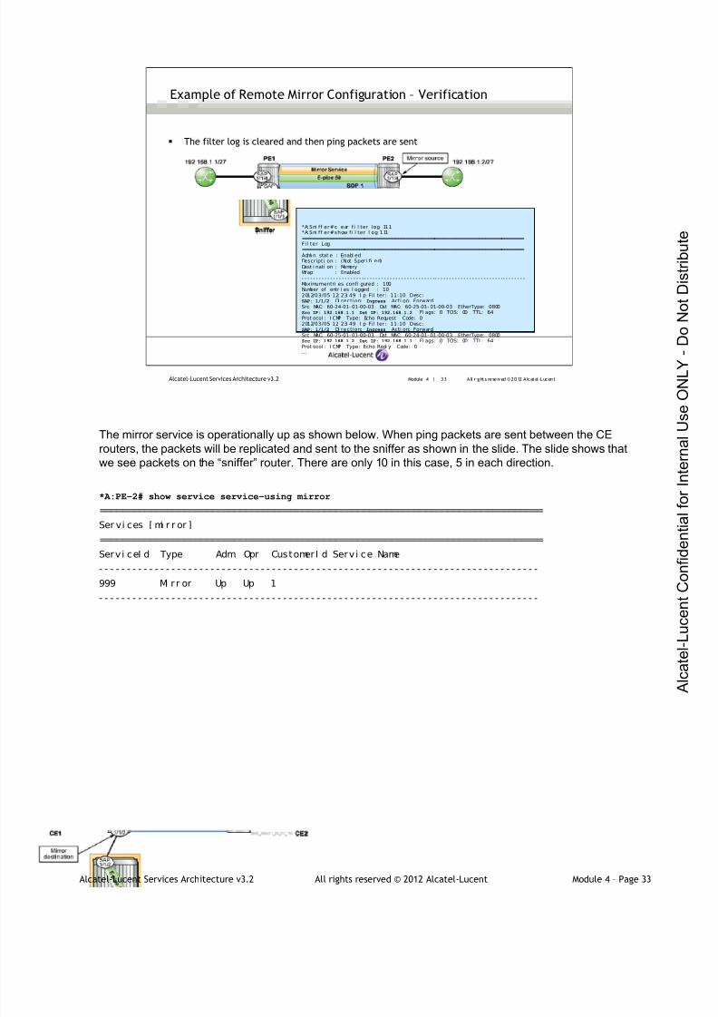
7/21/2019 Services Architecture v3.2 Student Guide Download
http://slidepdf.com/reader/full/services-architecture-v32-student-guide-download 262/429
Alcatel-Lucent Services Architecture v3.2 All rights reserved © 2012 Alcatel-Lucent Module 4 – Page 33
Module 4 | 33 A ll r ights re se rved ©2012 A lcatel -LucentAlcatel-Lucent Services Architecture v3.2
Example of Remote Mirror Configuration – Verification
The filter log is cleared and then ping packets are sent
*A:Sni ff er#cl ear f i l ter log 111*A:Sni ff er#show fi l ter l og 111===============================================================================Fil ter Log===============================================================================Admi n stat e : Enabl edDescripti on : (Not Speci fi ed)Dest i nati on : MemoryWr ap : Enabled- - - - - - - - - - - - - - - - - - - - - -- - - - - - - - - - - - - - - - - - - - - - - - -- - - - - - - - - - - - - - - - - - - - - - - -- - - - - - - -Maximumentri es confi gured : 100Number of entr i es l ogged : 102012/03/05 12: 23: 49 I p Fil ter: 11:10 Desc:SAP: 1/1/2 Di rection: Ingress Acti on: ForwardSrc MAC: 60-24-01- 01-00-03 Dst MAC: 60-25-01- 01-00-03 EtherType: 0800Src IP: 192.168.1.1 Dst IP: 192.168.1.2 Fl ags: 0 TOS: 00 TTL: 64Prot ocol : I CMP Type: Echo Request Code: 02012/03/05 12: 23: 49 I p Fil ter: 11:10 Desc:SAP: 1/1/2 Di rection: Ingress Acti on: ForwardSrc MAC: 60-25-01- 01-00-03 Dst MAC: 60-24-01- 01-00-03 EtherType: 0800Src IP: 192.168.1.2 Dst IP: 192.168.1.1 Fl ags: 0 TOS: 00 TTL: 64Prot ocol : I CMP Type: Echo Repl y Code: 0…
The mirror service is operationally up as shown below. When ping packets are sent between the CE
routers, the packets will be replicated and sent to the sniffer as shown in the slide. The slide shows that
we see packets on the “sniffer” router. There are only 10 in this case, 5 in each direction.
*A:PE-2# show service service-using mirror
===============================================================================
Ser vi ces [ mi r r or ]
===============================================================================
Servi ceI d Type Adm Opr CustomerI d Servi ce Name
- - - - - - - - - - - - - - - - - - - - - - - - - - - - - - - - - - - - - - - - - - - - - - - - - - - - - - - - - - - - - - - - - - - - - - - - - - - - - - -
999 Mi r r or Up Up 1
- - - - - - - - - - - - - - - - - - - - - - - - - - - - - - - - - - - - - - - - - - - - - - - - - - - - - - - - - - - - - - - - - - - - - - - - - - - - - - -

7/21/2019 Services Architecture v3.2 Student Guide Download
http://slidepdf.com/reader/full/services-architecture-v32-student-guide-download 263/429
Alcatel-Lucent Services Architecture v3.2 All rights reserved © 2012 Alcatel-Lucent Module 4 – Page 34
Module 4 | 34 A ll r ights re se rved ©2012 A lcatel -LucentAlcatel-Lucent Services Architecture v3.2
Remote Mirror Service — Filter-Based Source
Filter-based source configuration requirements:
Define a filter, either IP or MAC, with at least one entry
Apply that filter to a SAP or an IP interface
Under the debug mirror-source context, define one or more entries to the
filter, which will identify matching traffic for mirroring
The regular rules regarding filters still apply here; only one ingress and one egress filter are permitted, and
in each case either an IP filter or a MAC filter may be used, but not both. This example will use an IP filter.
The filter must be applied to a SAP or IP interface. If a filter is defined but not associated with a SAP or IP
interface, mirroring will not be enabled as there are no packets to mirror. In this example the filter is
applied to SAP 1/1/4 on PE2.
Simply having a filter applied to a SAP or IP interface does not cause mirroring; by default, none of the
packets matching any of the filter criteria are mirrored. The mirroring of packets must be explicitly definedby identifying the entries to use for matching.
All packets are mirrored as they appear on the wire. Ingress packets are mirrored as they appear before
any ingress modifications. Egress packets are mirrored as they appear after all egress modifications and
encapsulations have been applied.
Note: an IP filter cannot be applied to a mirror destination SAP. No change is necessary to the
configuration of the mirror destination (compared with the previous example).
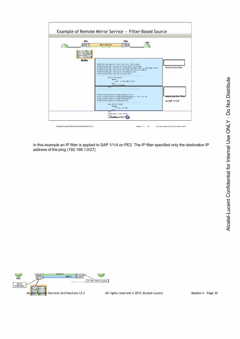
7/21/2019 Services Architecture v3.2 Student Guide Download
http://slidepdf.com/reader/full/services-architecture-v32-student-guide-download 264/429
Alcatel-Lucent Services Architecture v3.2 All rights reserved © 2012 Alcatel-Lucent Module 4 – Page 35
Module 4 | 35 A ll r ights re se rved ©2012 A lcatel -LucentAlcatel-Lucent Services Architecture v3.2
Example of Remote Mirror Service — Filter-Based Source
Define the filter
*A:PE-2# configure fi l t er i p-f i l ter 101 create*A:PE-2>confi g>fi l ter>i p-fi l ter$ entr y 10 create*A:PE-2>confi g>fi l ter>i p-fi l ter>entr y$ match dst-i p 192.168.1.0/27*A:PE-2>confi g>fi l ter>i p-fi l ter>entr y$ acti on f orward*A:PE-2>confi g>fi l ter>i p-fi l ter>entr y$ exi t*A:PE-2>config>fi l ter>i p-fi l ter# info- - - - - - - - - - - - - - - - - - - - - - - - - - - - - - - - - - - - - - - - - - - - - -
entr y 10 createmat ch
dst-i p 192.168.1.0/27exi tacti on f orward
exi t- - - - - - - - - - - - - - - - - - - - - - - - - - - - - - - - - - - - - - - - - - - - - -
*A:PE-2>conf i g>servi ce>epi pe#sap 1/1/ 4*A:PE-2>conf i g>servi ce>epi pe>sap#egress fi l ter i p 101*A:PE-2>conf i g>servi ce>epi pe>sap#exi t*A:PE-2>conf i g>servi ce>epi pe#i nfo- - - - - - - - - - - - - - - - - - - - - - - - - - - - - - - - - - - - - - - - - - - - - -
sap 1/1/ 4 createegress
f i l t er i p 101exi t
exi tspoke-sdp 1:50 createexi tno shut down
Applying the filter
to SAP 1/1/4
In this example an IP filter is applied to SAP 1/1/4 on PE2. The IP filter specified only the destination IP
address of the ping (192.168.1.0/27)
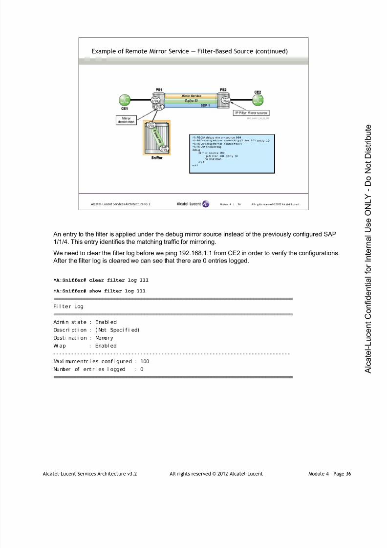
7/21/2019 Services Architecture v3.2 Student Guide Download
http://slidepdf.com/reader/full/services-architecture-v32-student-guide-download 265/429
Alcatel-Lucent Services Architecture v3.2 All rights reserved © 2012 Alcatel-Lucent Module 4 – Page 36
Module 4 | 36 A ll r ights re se rved ©2012 A lcatel -LucentAlcatel-Lucent Services Architecture v3.2
Example of Remote Mirror Service — Filter-Based Source (continued)
*A:PE-2# debug mi rr or- source 999*A:PE-2>debug>mi rr or- source#i p-f i l ter 101 entry 10*A:PE-2>debug>mi rr or- source#exi t*A:PE-2# showdebugdebug
mi rr or- source 999i p-fi l ter 101 entr y 10no shut down
exi texi t
An entry to the filter is applied under the debug mirror source instead of the previously configured SAP
1/1/4. This entry identifies the matching traffic for mirroring.
We need to clear the filter log before we ping 192.168.1.1 from CE2 in order to verify the configurations.
After the filter log is cleared we can see that there are 0 entries logged.
*A:Sniffer# clear filter log 111
*A:Sniffer# show filter log 111
===============================================================================
Fi l ter Log
===============================================================================
Admi n st ate : Enabl ed
Descri pt i on : ( Not Speci f i ed)
Dest i nat i on : Memory
Wr ap : Enabl ed
- - - - - - - - - - - - - - - - - - - - - - - - - - - - - - - - - - - - - - - - - - - - - - - - - - - - - - - - - - - - - - - - - - - - - - - - - - - - - - -
Maxi mumentr i es conf i gur ed : 100
Number of ent r i es l ogged : 0
===============================================================================

7/21/2019 Services Architecture v3.2 Student Guide Download
http://slidepdf.com/reader/full/services-architecture-v32-student-guide-download 266/429
Alcatel-Lucent Services Architecture v3.2 All rights reserved © 2012 Alcatel-Lucent Module 4 – Page 37
Module 4 | 37 A ll r ights re se rved ©2012 A lcatel -LucentAlcatel-Lucent Services Architecture v3.2
Example of Remote Mirror Service — Filter-Based Source (continued)
*A:Sni ff er#show fi l ter l og 111===============================================================================Fil ter Log===============================================================================Admi n stat e : Enabl edDescripti on : (Not Specif i ed)Dest i nati on : MemoryWrap : Enabl ed- - - - - - - - - - - - - - - - - - - - - - - -- - - - - - - - - - - - - - - - - - - - - - - -- - - - - - - - - - - - - - - - - - - - - - - - -- - - - - -Maximumentri es confi gured : 100Number of entr i es l ogged : 5
2012/ 03/ 05 15: 54: 48 I p Fil ter: 11:10 Desc:SAP: 1/1/2 Di recti on: I ngress Acti on: ForwardSrc MAC: 60-24-01- 01-00-03 Dst MAC: 60-25-01- 01-00-03 EtherType: 0800Src IP: 192.168.1.1 Dst IP: 192.168.1.2 Fl ags: 0 TOS: 00 TTL: 64Prot ocol : I CMP Type: Echo Repl y Code: 02012/ 03/ 05 15: 54: 49 I p Fil ter: 11:10 Desc:SAP: 1/1/2 Di recti on: I ngress Acti on: ForwardSrc MAC: 60-24-01- 01-00-03 Dst MAC: 60-25-01- 01-00-03 EtherType: 0800Src IP: 192.168.1.1 Dst IP: 192.168.1.2 Fl ags: 0 TOS: 00 TTL: 64Prot ocol : I CMP Type: Echo Repl y Code. . .
Ping packets are sent to the far-end CE (CE1) router as shown:
*A:CE2# ping 192.168.1.1
PI NG 192. 168. 1. 1 56 dat a byt es
64 byt es f r om 192. 168. 1. 1: i cmp_seq=1 t t l =64 t i me=2. 31ms.
64 byt es f r om 192. 168. 1. 1: i cmp_seq=2 t t l =64 t i me=2. 30ms.
64 byt es f r om 192. 168. 1. 1: i cmp_seq=3 t t l =64 t i me=2. 31ms.
64 byt es f r om 192. 168. 1. 1: i cmp_seq=4 t t l =64 t i me=2. 29ms.
64 byt es f r om 192. 168. 1. 1: i cmp_seq=5 t t l =64 t i me=4. 34ms.
- - - - 192. 168. 1. 1 PI NG Stat i st i cs - - - -
5 packet s t r ansmi t t ed, 5 packet s r ecei ved, 0. 00% packet l oss
The slide shows that we see packets on the “sniffer” router. There are only five in this case (only two are
shown) since the IP filter for the mirror source specified only the destination IP address of the ping.

7/21/2019 Services Architecture v3.2 Student Guide Download
http://slidepdf.com/reader/full/services-architecture-v32-student-guide-download 267/429
Alcatel-Lucent Services Architecture v3.2 All rights reserved © 2012 Alcatel-Lucent Module 4 – Page 38
Module 4 | 38 A ll r ights re se rved ©2012 A lcatel -LucentAlcatel-Lucent Services Architecture v3.2
Mirror Slicing
Mirror service allows network operators to ‘slice’ customer data, mirroring
only the parts they need to analyze
Allows only a specified number of bytes to be transmitted to the mirror
destination
Enables the copying of a specific packet size of each frame
Can monitor network usage without copying the actual data
Can mirror large frames
Limits the size of the stream of packets traveling through the router and
the network
In traditional routers, replication of mirrored packets typically affected performance and needed to be used
with caution. Due to the duplication of some or all packets, the total amount of traffic within the network
would increase, possibly causing congestion in downstream links and routers.
The replication of packets is handled by the hardware on the IOM (Input/Output Module) and thus has
minimal impact on router performance. However, it is important to remember that mirroring involves the
duplication of traffic and thus increases the bandwidth required. If ingress and egress traffic on a 1 Gb/s
port is mirrored, this could represent as much as an additional 2 Gb/s of traffic to the mirror destination.
When a mirror destination is configured, the packet slice option can truncate mirrored packets to the
destination. This minimizes replication and tunneling overhead.
Slicing is useful for monitoring network usage without having to copy the actual data. Slicing enables you
to mirror frames larger than the destination-packet decode equipment can handle. It also enables the
conservation of mirroring resources by limiting the size of the stream of packets traveling through the SR
and the core network.
When a mirror slice size is defined, a threshold is created that truncates a mirrored frame to a specific
size. For example, if the value of 256 bytes is defined, up to the first 256 bytes of the frame are transmitted
to the mirror destination. The original frame is not affected by the truncation. Mirrored frames will most
likely be slightly larger due to encapsulation overhead, but no more than 256 bytes of the original packet
will be transmitted.
The transmission of a sliced or non-sliced frame is also dependent on the mirror destination SDP path
MTU and/or the mirror destination SAP physical MTU. Packets that require a larger MTU than the
mirroring destination supports are discarded if the defined slice size does not truncate the packet to an
acceptable size.
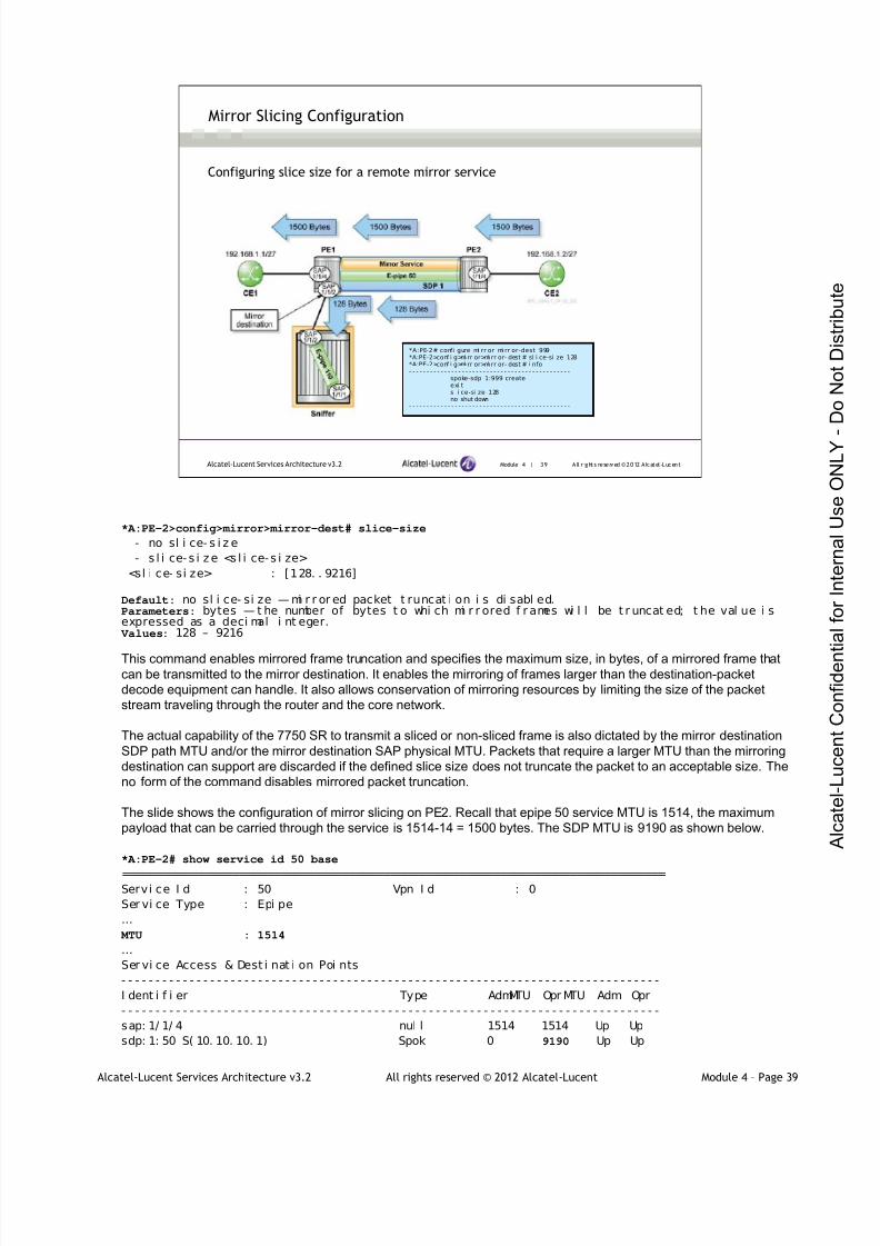
7/21/2019 Services Architecture v3.2 Student Guide Download
http://slidepdf.com/reader/full/services-architecture-v32-student-guide-download 268/429
Alcatel-Lucent Services Architecture v3.2 All rights reserved © 2012 Alcatel-Lucent Module 4 – Page 39
Module 4 | 39 A ll r ights re se rved ©2012 A lcatel -LucentAlcatel-Lucent Services Architecture v3.2
Mirror Slicing Configuration
Configuring slice size for a remote mirror service
*A:PE-2# confi gure mi rr or mi rr or-dest 999*A:PE-2>conf i g>mi rr or>mi rr or- dest # sl i ce-si ze 128*A:PE-2>conf i g>mi rr or>mi rr or- dest # i nfo- - - - - - - - - - - - - - - - - - - - - - - - - - - - - - - - - - - - - - - - - - - - - -
spoke-sdp 1:999 createexi tsl i ce-si ze 128no shut down
- - - - - - - - - - - - - - - - - - - - - - - - - - - - - - - - - - - - - - - - - - - - - -
*A:PE-2>config>mirror>mirror-dest# slice-size
- no sl i ce- s i z e
- s l i ce- s i ze <s l i ce- s i ze>
<sl i ce- si ze> : [128. . 9216]
Default: no sl i ce- si ze — mi r r or ed packet t runcat i on i s di sabl ed.Parameters: bytes — t he number of bytes t o whi ch mi r r ored f r ames wi l l be t r uncat ed; t he val ue i sexpressed as a deci mal i nt eger.
Values: 128 – 9216
This command enables mirrored frame truncation and specifies the maximum size, in bytes, of a mirrored frame thatcan be transmitted to the mirror destination. It enables the mirroring of frames larger than the destination-packet
decode equipment can handle. It also allows conservation of mirroring resources by limiting the size of the packet
stream traveling through the router and the core network.
The actual capability of the 7750 SR to transmit a sliced or non-sliced frame is also dictated by the mirror destination
SDP path MTU and/or the mirror destination SAP physical MTU. Packets that require a larger MTU than the mirroring
destination can support are discarded if the defined slice size does not truncate the packet to an acceptable size. The
no form of the command disables mirrored packet truncation.
The slide shows the configuration of mirror slicing on PE2. Recall that epipe 50 service MTU is 1514, the maximum
payload that can be carried through the service is 1514-14 = 1500 bytes. The SDP MTU is 9190 as shown below.
*A:PE-2# show service id 50 base
===============================================================================Servi ce I d : 50 Vpn I d : 0
Ser vi ce Type : Epi pe
…
MTU : 1514
…
Ser vi ce Access & Dest i nat i on Poi nts
- - - - - - - - - - - - - - - - - - - - - - - - - - - - - - - - - - - - - - - - - - - - - - - - - - - - - - - - - - - - - - - - - - - - - - - - - - - - - - -
I dent i f i er Type AdmMTU Opr MTU Adm Opr
- - - - - - - - - - - - - - - - - - - - - - - - - - - - - - - - - - - - - - - - - - - - - - - - - - - - - - - - - - - - - - - - - - - - - - - - - - - - - - -
sap: 1/ 1/ 4 nul l 1514 1514 Up Up
sdp: 1: 50 S( 10. 10. 10. 1) Spok 0 9190 Up Up

7/21/2019 Services Architecture v3.2 Student Guide Download
http://slidepdf.com/reader/full/services-architecture-v32-student-guide-download 269/429
Alcatel-Lucent Services Architecture v3.2 All rights reserved © 2012 Alcatel-Lucent Module 4 – Page 40
Module 4 | 40 A ll r ights re se rved ©2012 A lcatel -LucentAlcatel-Lucent Services Architecture v3.2
Mirror Slicing Verification
*A:Snif fer# showf i lt er ip 11 counters=======================================================================IP Fi l ter=======================================================================Fil ter I d : 11 Appl i ed : YesScope : Templat e Def. Acti on : DropRadi us Ins Pt: n/aCrCtl . I ns Pt: n/aEntr i es : 1Descripti on : (Not Specif i ed)- - - - - - - - - - - - - - - - - - - - - - -- - - - - - - - - - - - - - - - - - - - - - - -- - - - - - - - - - - - - - - - - - - - - - - -Fi l ter Match Cri teri a : I P- - - - - - - - - - - - - - - - - - - - - - -- - - - - - - - - - - - - - - - - - - - - - - -- - - - - - - - - - - - - - - - - - - - - - - -Entr y : 10Ing. Matches : 1 pkts (132 bytes)
Egr. Matches : 0 pkts
*A: CE2# pi ng count 1 192. 168. 1. 1 size 1200
PI NG 192.168. 1.1 1200 data bytes1208 bytes f rom 192. 168. 1. 1: i cmp_seq=1 tt l =64 ti me=3.08ms.
- - - - 192 .168.1 .1 PINGStat i st i cs - - - -1 packet t ransmi tt ed, 1 packet r eceived, 0. 00%packet l ossround- tr i p mi n = 3.08ms, avg = 3.08ms, max = 3.08ms, st ddev = 0.000ms
To verify mirror slicing, we have cleared the filter IP (see below), therefore there are no packets captured.Then we sent a ping from CE2 to CE1 with a size of 1200 byte, as shown in the slide (the size valuespecifies the size of the ping packet; recall that the maximum size for a successful ping would be 1472bytes). If we check the IP filter counter we see (as expected) there is only one packet that has beenmatched on the ingress, and the size of that packet is 132 bytes - 4 bytes more than the 128 bytesconfigured in the mirror slicing due to encapsulation overhead.
* A: Sni f f er# cl ear f i l t er i p 11
*A: Sni f f er# show f i l ter i p 11 counters======================================================================
I P Fi l t er
======================================================================
Filter Id : 11 Appl i ed : Yes
Scope : Templ ate Def . Act i on : Dr op
Radi us I ns Pt: n/ a
CrCt l . I ns Pt: n/ a
Ent ri es : 1
Descri pt i on : (Not Speci f i ed)
- - - - - - - - - - - - - - - - - - - - - - - - - - - - - - - - - - - - - - - - - - - - - - - - - - - - - - - - - - - - - - - - - - - - - - -
Fi l ter Match Cri ter i a : I P
- - - - - - - - - - - - - - - - - - - - - - - - - - - - - - - - - - - - - - - - - - - - - - - - - - - - - - - - - - - - - - - - - - - - - - -
Entry : 10
Ing. Matches : 0 pktsEgr . Matches : 0 pkt s

7/21/2019 Services Architecture v3.2 Student Guide Download
http://slidepdf.com/reader/full/services-architecture-v32-student-guide-download 270/429
Alcatel-Lucent Services Architecture v3.2 All rights reserved © 2012 Alcatel-Lucent Module 4 – Page 41
Module 4 | 41 A ll r ights re se rved ©2012 A lcatel -LucentAlcatel-Lucent Services Architecture v3.2
Module Summary
OAM tools are provided in modern routers to help manage and troubleshoot
the network
lsp-ping command is used to verify LSP connectivity
lsp-trace command is used to determine the hop-by-hop path for an LSP
sdp-mtu performs in-band MTU path tests on an SDP to determine the
largest path MTU supported on an SDP
sdp-ping tests an SDP for in-band unidirectional or round-trip connectivity
with a round-trip time estimate
svc-ping tests a service ID for correct and consistent provisioning between
two service end-points
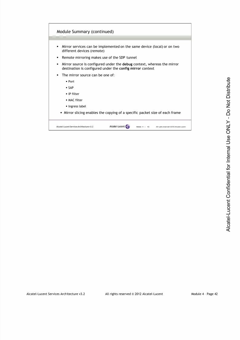
7/21/2019 Services Architecture v3.2 Student Guide Download
http://slidepdf.com/reader/full/services-architecture-v32-student-guide-download 271/429
Alcatel-Lucent Services Architecture v3.2 All rights reserved © 2012 Alcatel-Lucent Module 4 – Page 42
Module 4 | 42 A ll r ights re se rved ©2012 A lcatel -LucentAlcatel-Lucent Services Architecture v3.2
Module Summary (continued)
Mirror services can be implemented on the same device (local) or on two
different devices (remote)
Remote mirroring makes use of the SDP tunnel
Mirror source is configured under the debug context, whereas the mirror
destination is configured under the config mirror context
The mirror source can be one of:
Port
SAP
IP filter
MAC filter
Ingress label
Mirror slicing enables the copying of a specific packet size of each frame

7/21/2019 Services Architecture v3.2 Student Guide Download
http://slidepdf.com/reader/full/services-architecture-v32-student-guide-download 272/429
Alcatel-Lucent Services Architecture v3.2 All rights reserved © 2012 Alcatel-Lucent Module 4 – Page 43
Module 4 | 43 A ll r ights re se rved ©2012 A lcatel -LucentAlcatel-Lucent Services Architecture v3.2
Learning Assessment
1. What are the OAM SDP diagnostic tools?
2. What is lsp-ping used for?
3. Why is the path MTU found using sdp-mtu 4 bytes less than the MTUdiscovered using lsp-ping?
4. In oam svc-ping, what do the parameters local-sdp and remote-sdp
indicate?
5. Verify whether the following statement is true or false: Traffic from
more than one ingress mirror source can be mirrored to the same traffic
analyzer using different SAPs on the same access port.
6. How many SDPs in total are involved in local mirroring?
7. How many mirror destinations can a mirror source have within a mirror
service?
1. What are the OAM SDP diagnostic tools?
The OAM SDP diagnostic tools are sdp-ping and sdp-mtu
2. What is lsp-ping used for?
lsp-ping can be used for measuring the round trip time for a specific forwarding class, or testing the
path MTU
3. Why is the path MTU found using sdp-mtu 4 bytes less than the MTU discovered using lsp-ping?
The path MTU found using sdp-mtu is 4 bytes less than the MTU discovered using lsp-ping because
lsp-ping uses only a single MPLS label, while sdp-mtu uses both the service and transport label.
4. In oam svc-ping, what do the parameters local-sdp and remote-sdp indicate?
The parameter local-sdp specifies that the ping should be sent to the far-end in-band using the SDP
and the parameter remote-sdp specifies that the return ping should be sent in-band
5. Verify whether the following statement is true or false: Traffic from more than one ingress mirror source
can be mirrored to the same traffic analyzer using different SAPs
True
6. How many SDPs in total are involved in local mirroring?
None
7. Within a mirror service, how many mirror destinations can a mirror source have?
One
7/21/2019 Services Architecture v3.2 Student Guide Download
http://slidepdf.com/reader/full/services-architecture-v32-student-guide-download 273/429
Alcatel-Lucent Services Architecture v3.2 All rights reserved © 2012 Alcatel-Lucent Module 4 – Page 44
Module 4 | 44 A ll r ights re se rved ©2012 A lcatel -LucentAlcatel-Lucent Services Architecture v3.2
Learning Assessment (continued)
8. What happens to a mirror source when the corresponding mirror
destination service ID is shut down?
9. Which command syntax is used to configure a mirror source? Which
command syntax is used to configure a mirror destination?
10. Verify whether the following statement is true or false: With local
mirroring, the local mirror source and mirror destination components
must be configured using the same service ID.
8. What happens to a mirror source when the corresponding mirror destination service ID is shut down?
The mirror source is put into an operational down mode.
9. Which command syntax is used to configure a mirror source? Which command syntax is used to
configure a mirror destination?
A mirror source uses the debug>mirror-source context, while the mirror destination uses the
config>mirror context.
10.Verify whether the following statement is true or false: With local mirroring, the local mirror source and
mirror destination components must be configured under the same service ID context.
True

7/21/2019 Services Architecture v3.2 Student Guide Download
http://slidepdf.com/reader/full/services-architecture-v32-student-guide-download 274/429
Alcatel-Lucent Services Architecture v3.2 All rights reserved © 2012 Alcatel-Lucent Module 4 – Page 45
Module 4 | 45 A ll r ights re se rved ©2012 A lcatel -LucentAlcatel-Lucent Services Architecture v3.2
Lab 6-1 ― Local Mirror Service
In this lab you will:
Configure a local mirror service

7/21/2019 Services Architecture v3.2 Student Guide Download
http://slidepdf.com/reader/full/services-architecture-v32-student-guide-download 275/429
Alcatel-Lucent Services Architecture v3.2 All rights reserved © 2012 Alcatel-Lucent Module 4 – Page 46
Module 4 | 46 A ll r ights re se rved ©2012 A lcatel -LucentAlcatel-Lucent Services Architecture v3.2
Lab 6-2 ― Remote Mirror Service
In this lab you will:
Configure a remote mirror service

7/21/2019 Services Architecture v3.2 Student Guide Download
http://slidepdf.com/reader/full/services-architecture-v32-student-guide-download 276/429
Module 4 | 47 A ll r ights re se rved ©2012 A lcatel -LucentAlcatel-Lucent Services Architecture v3.2
www.alcatel-lucent.com/src
3FL-30636-AAAA-ZZZZA Edition 01

7/21/2019 Services Architecture v3.2 Student Guide Download
http://slidepdf.com/reader/full/services-architecture-v32-student-guide-download 277/429
Alcatel-Lucent Services Architecture v3.2 All rights reserved © 2012 Alcatel-Lucent Module 5 – Page 1
Alcatel-Lucent Services Architecture
Module 5 — Layer 3 Services
7/21/2019 Services Architecture v3.2 Student Guide Download
http://slidepdf.com/reader/full/services-architecture-v32-student-guide-download 278/429
Alcatel-Lucent Services Architecture v3.2 All rights reserved © 2012 Alcatel-Lucent Module 5 – Page 2
Module 5 | 2 All r ights reserved ©2012 Alcatel-LucentAlcatel-Lucent Services Architecture v3.2
Module Objectives
After successfully completing this module, you will be able to:
Provide an overview of IES and its features
Describe the operation and implementation of an IES
Configure and verify an IES
Describe the application of Layer 3 service spoke termination
to a Layer 2 service
Configure and verify an IES spoke termination to a VPLS
Alcatel-Lucent Services Archi tecture
This course is part of the Alcatel-Lucent Service Routing Certification (SRC) program. Refer to the
Alcatel-Lucent website located at www.alcatel-lucent.com/src for more information on the SRC
program.
To locate additional information relating to the topics presented in this manual, refer to the following:
•Technical Practices for the specific product
•Internet standards documentation such as protocol standards bodies, RFCs, and IETF drafts
•Technical support pages of the Alcatel-Lucent website located at http://www.alcatel-
lucent.com/support

7/21/2019 Services Architecture v3.2 Student Guide Download
http://slidepdf.com/reader/full/services-architecture-v32-student-guide-download 279/429
Alcatel-Lucent Services Architecture v3.2 All rights reserved © 2012 Alcatel-Lucent Module 5 – Page 3
Module 5 | 3 All r ights reserved ©2012 Alcatel-LucentAlcatel-Lucent Services Architecture v3.2
Module Objectives (continued)
Describe the Alcatel-Lucent VPRN service and recognize itsbenefits
Identify the protocols and technologies required toimplement the Alcatel-Lucent VPRN service
Explain the interaction between the control and data planeof a VPRN service
Configure, verify and troubleshoot an IPv4 and IPv6 VPRNservice

7/21/2019 Services Architecture v3.2 Student Guide Download
http://slidepdf.com/reader/full/services-architecture-v32-student-guide-download 280/429
Alcatel-Lucent Services Architecture v3.2 All rights reserved © 2012 Alcatel-Lucent Module 5 – Page 4
Module 5 — Layer 3 Services
Section 1 — Internet Enhanced Service (IES) Overview

7/21/2019 Services Architecture v3.2 Student Guide Download
http://slidepdf.com/reader/full/services-architecture-v32-student-guide-download 281/429
Alcatel-Lucent Services Architecture v3.2 All rights reserved © 2012 Alcatel-Lucent Module 5 – Page 5
Module 5 | 5 All r ights reserved ©2012 Alcatel-LucentAlcatel-Lucent Services Architecture v3.2
Section Objectives
After successfully completing this section, you will be able to:
Describe customer access to IES
Explain IES characteristics
Configure and verify an IES
Complete Lab 7 — Configuring an IES
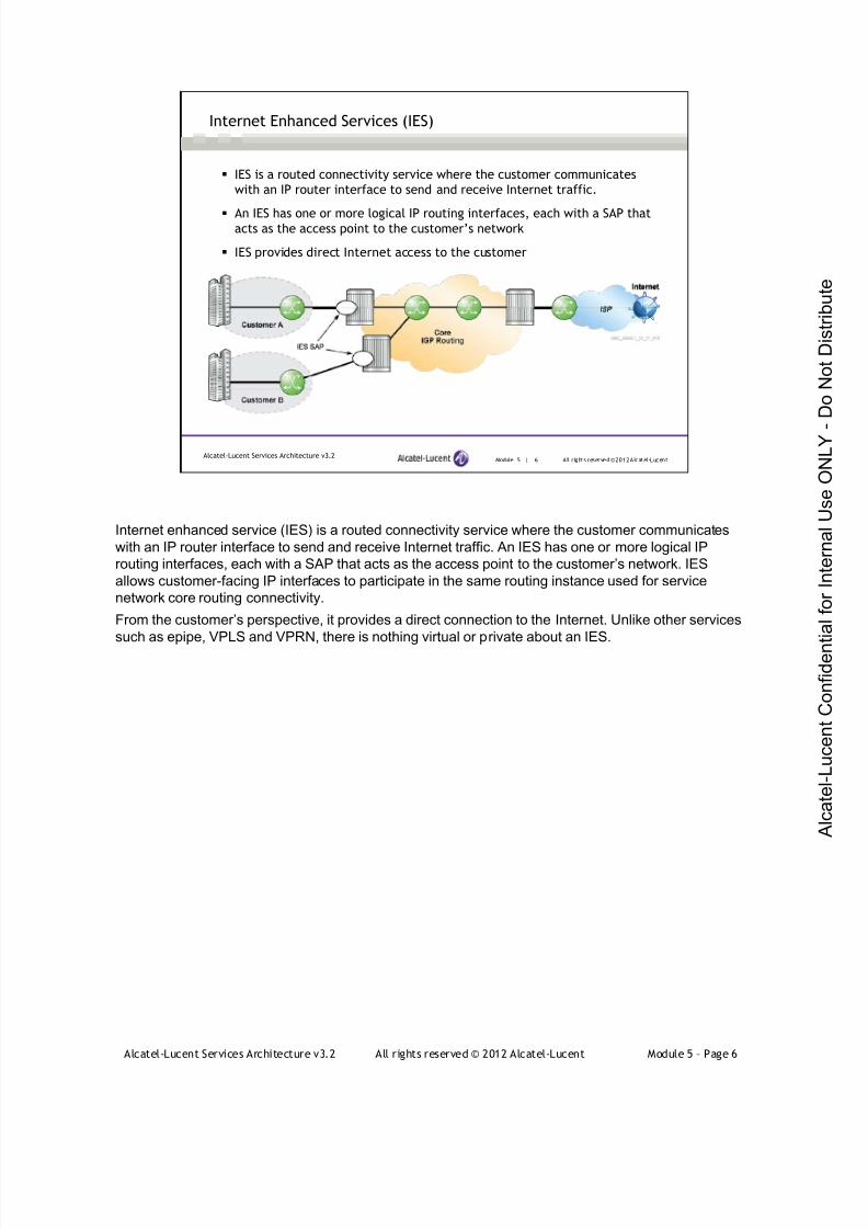
7/21/2019 Services Architecture v3.2 Student Guide Download
http://slidepdf.com/reader/full/services-architecture-v32-student-guide-download 282/429
Alcatel-Lucent Services Architecture v3.2 All rights reserved © 2012 Alcatel-Lucent Module 5 – Page 6
Module 5 | 6 All r ights reserved ©2012 Alcatel-LucentAlcatel-Lucent Services Architecture v3.2
Internet Enhanced Services (IES)
IES is a routed connectivity service where the customer communicates
with an IP router interface to send and receive Internet traffic.
An IES has one or more logical IP routing interfaces, each with a SAP thatacts as the access point to the customer’s network
IES provides direct Internet access to the customer
Internet enhanced service (IES) is a routed connectivity service where the customer communicates
with an IP router interface to send and receive Internet traffic. An IES has one or more logical IP
routing interfaces, each with a SAP that acts as the access point to the customer’s network. IES
allows customer-facing IP interfaces to participate in the same routing instance used for service
network core routing connectivity.
From the customer’s perspective, it provides a direct connection to the Internet. Unlike other services
such as epipe, VPLS and VPRN, there is nothing virtual or private about an IES.

7/21/2019 Services Architecture v3.2 Student Guide Download
http://slidepdf.com/reader/full/services-architecture-v32-student-guide-download 283/429
Alcatel-Lucent Services Architecture v3.2 All rights reserved © 2012 Alcatel-Lucent Module 5 – Page 7
Module 5 | 7 All r ights reserved ©2012 Alcatel-LucentAlcatel-Lucent Services Architecture v3.2
IES Characteristics
Multiple IES services are created to separate customer-owned IP interfaces
More than one IES service can be created for a single customer ID
Multiple interfaces can be configured in a single IES
All IP interfaces created within an IES belong to the same customer
IES allows customer-facing IP interfaces to participate in the same routing
instance used for service network core routing connectivity
The service provider can apply all billing, QoS and accounting to the
customer
Does not necessarily require a service distribution path (SDP); traffic is
routed rather than encapsulated in a tunnel
The Internet Enhanced Service (IES) is essentially a way of providing a Layer 3 interface to a
customer. It is similar to a normal Layer 3 interface, but treated as a service, with the port configured
as a SAP (SAPs support multiple encapsulation types such as Ethernet null, dot1Q, Q-in-Q.). This
provides more flexibility and also the ability to use all service-oriented capabilities of an access port
such as QoS, accounting and filtering. Like any IP interface, the customer can use the IES interface as
a neighbor for a routing protocol such as OSPF, IS-IS or BGP. The IES provides access to the service
provider’s core routing instance.
Since the traffic in an IES communicates using an IP interface for the core routing instance, there is no
need for the concept of tunneling traffic to a remote router. As such, a simple IES does not necessarily
require the configuration of any SDPs when configuring the service.
In the following section we will discuss how an IES can provide Layer 3 termination of a Layer 2 VPLS
service. In that case, a spoke SDP is used in conjunction with an IES.
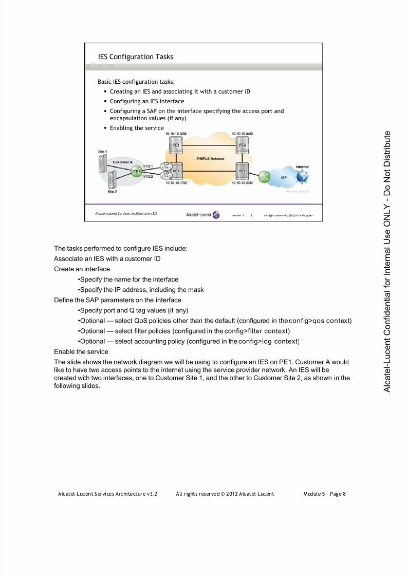
7/21/2019 Services Architecture v3.2 Student Guide Download
http://slidepdf.com/reader/full/services-architecture-v32-student-guide-download 284/429
Alcatel-Lucent Services Architecture v3.2 All rights reserved © 2012 Alcatel-Lucent Module 5 – Page 8
Module 5 | 8 All r ights reserved ©2012 Alcatel-LucentAlcatel-Lucent Services Architecture v3.2
IES Configuration Tasks
Basic IES configuration tasks:
Creating an IES and associating it with a customer ID
Configuring an IES interface
Configuring a SAP on the interface specifying the access port and
encapsulation values (if any)
Enabling the service
The tasks performed to configure IES include:
Associate an IES with a customer ID
Create an interface
•Specify the name for the interface
•Specify the IP address, including the mask
Define the SAP parameters on the interface•Specify port and Q tag values (if any)
•Optional — select QoS policies other than the default (configured in the config>qos context)
•Optional — select filter policies (configured in the config>filter context)
•Optional — select accounting policy (configured in the config>log context)
Enable the service
The slide shows the network diagram we will be using to configure an IES on PE1. Customer A would
like to have two access points to the internet using the service provider network. An IES will be
created with two interfaces, one to Customer Site 1, and the other to Customer Site 2, as shown in the
following slides.
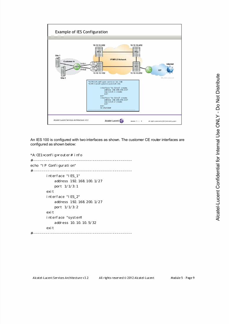
7/21/2019 Services Architecture v3.2 Student Guide Download
http://slidepdf.com/reader/full/services-architecture-v32-student-guide-download 285/429
Alcatel-Lucent Services Architecture v3.2 All rights reserved © 2012 Alcatel-Lucent Module 5 – Page 9
Module 5 | 9 All r ights reserved ©2012 Alcatel-LucentAlcatel-Lucent Services Architecture v3.2
Example of IES Configuration
*A: PE-1# confi gure servi ce ies 100*A:PE-1>confi g>servi ce>i es# i nfo- - - - - - - - - - - - - - - - - - - - - - - - - - - - - - - - - - - - - - - - - - - - - -
i nterface "to- Sit e1" createaddress 192.168.100. 2/27sap 1/1/4: 1 createexi t
exi ti nterface "to- Sit e2" create
address 192.168.200. 2/27sap 1/1/4: 2 createexi t
exi tno shut down
- - - - - - - - - - - - - - - - - - - - - - - - - - - - - - - - - - - - - - - - - - - - - -
An IES 100 is configured with two interfaces as shown. The customer CE router interfaces are
configured as shown below:
*A: CE1>conf i g>r out er # i nf o
#- - - - - - - - - - - - - - - - - - - - - - - - - - - - - - - - - - - - - - - - - - - - - - - - - -
echo "I P Conf i gur ati on"
#- - - - - - - - - - - - - - - - - - - - - - - - - - - - - - - - - - - - - - - - - - - - - - - - - -i nt er f ace "I ES_1"
address 192. 168. 100. 1/ 27
por t 1/ 1/ 3: 1
exi t
i nt er f ace "I ES_2"
address 192. 168. 200. 1/ 27
por t 1/ 1/ 3: 2
exi t
i nt erf ace "syst em"
addr ess 10. 10. 10. 5/ 32
exi t
#- - - - - - - - - - - - - - - - - - - - - - - - - - - - - - - - - - - - - - - - - - - - - - - - - -
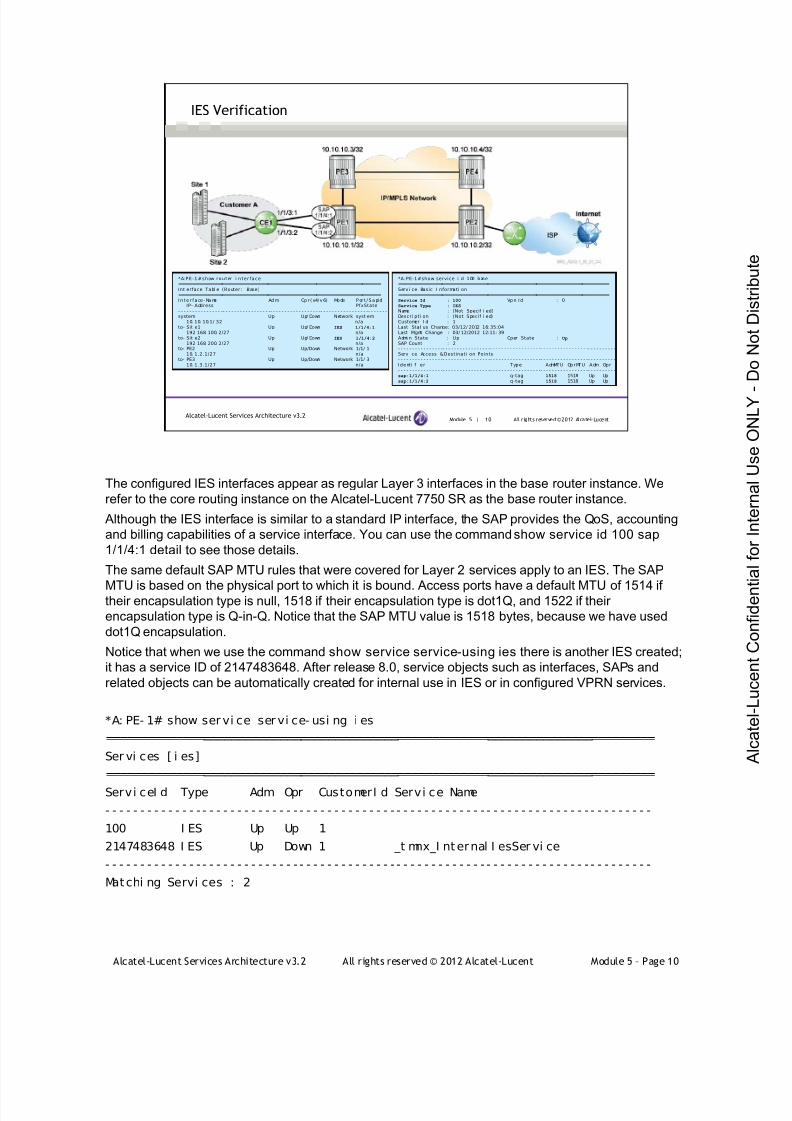
7/21/2019 Services Architecture v3.2 Student Guide Download
http://slidepdf.com/reader/full/services-architecture-v32-student-guide-download 286/429
Alcatel-Lucent Services Architecture v3.2 All rights reserved © 2012 Alcatel-Lucent Module 5 – Page 10
Module 5 | 10 All r ights reserved ©2012 Alcatel-LucentAlcatel-Lucent Services Architecture v3.2
IES Verification
*A:PE-1#show router i nter face===========================================================================Int erface Tabl e (Router: Base)===========================================================================I nte r face -Name Ad m Op r (v4/ v6) Mode P or t / S apI d
IP- Address PfxState- - - - - - - - - - - - - - - -- - - - - - - - - - - - - - - - -- - - - - - - - - - - - - - - - - -- - - - - - - - - - - - - - - - -- - - - - - -system Up Up/ Down Network syst em
10. 10. 10.1/ 32 n/ato- Sit e1 Up Up/ Down IES 1/1/4:1
192. 168. 100. 2/27 n/ato- Sit e2 Up Up/ Down IES 1/1/4:2
192. 168. 200. 2/27 n/ato- PE2 Up Up/Down Network 1/1/ 1
10. 1.2.1/27 n/ato- PE3 Up Up/Down Network 1/1/ 3
10. 1.3.1/27 n/a
*A:PE-1#show service i d 100 base==============================================================================Servi ce Basic I nformati on==============================================================================Service Id : 100 Vp n I d : 0Service Type : IES
Name : (Not Specif i ed)Descri pti on : (Not Specif i ed)Customer I d : 1Last Stat us Change: 03/12/ 2012 16: 35:04Last Mgmt Change : 03/ 12/2012 12:11: 39Admi n State : Up Oper State : Up
SAP Count : 2- - - - - - - - - - - - - - - -- - - - - - - - - - - - - - - - -- - - - - - - - - - - - - - - - - -- - - - - - - - - - - - - - - - -- - - - - - - - - -Servi ce Access &Destinati on Points- - - - - - - - - - - - - - - -- - - - - - - - - - - - - - - - -- - - - - - - - - - - - - - - - - -- - - - - - - - - - - - - - - - -- - - - - - - - - -Identi f i er Type AdmMTU OprMTU Adm Opr- - - - - - - - - - - - - - - -- - - - - - - - - - - - - - - - -- - - - - - - - - - - - - - - - - -- - - - - - - - - - - - - - - - -- - - - - - - - - -sap:1/1/4:1 q-tag 1518 1518 Up Upsap:1/1/4:2 q-tag 1518 1518 Up Up
The configured IES interfaces appear as regular Layer 3 interfaces in the base router instance. We
refer to the core routing instance on the Alcatel-Lucent 7750 SR as the base router instance.
Although the IES interface is similar to a standard IP interface, the SAP provides the QoS, accounting
and billing capabilities of a service interface. You can use the command show service id 100 sap
1/1/4:1 detail to see those details.
The same default SAP MTU rules that were covered for Layer 2 services apply to an IES. The SAP
MTU is based on the physical port to which it is bound. Access ports have a default MTU of 1514 iftheir encapsulation type is null, 1518 if their encapsulation type is dot1Q, and 1522 if their
encapsulation type is Q-in-Q. Notice that the SAP MTU value is 1518 bytes, because we have used
dot1Q encapsulation.
Notice that when we use the command show service service-using ies there is another IES created;
it has a service ID of 2147483648. After release 8.0, service objects such as interfaces, SAPs and
related objects can be automatically created for internal use in IES or in configured VPRN services.
*A: PE- 1# show ser vi ce ser vi ce- usi ng i es
===============================================================================
Ser vi ces [ i es]
===============================================================================
Servi ceI d Type Adm Opr CustomerI d Servi ce Name
- - - - - - - - - - - - - - - - - - - - - - - - - - - - - - - - - - - - - - - - - - - - - - - - - - - - - - - - - - - - - - - - - - - - - - - - - - - - - - -
100 I ES Up Up 1
2147483648 I ES Up Down 1 _t mnx_I nternal I esSer vi ce
- - - - - - - - - - - - - - - - - - - - - - - - - - - - - - - - - - - - - - - - - - - - - - - - - - - - - - - - - - - - - - - - - - - - - - - - - - - - - - -
Matchi ng Servi ces : 2
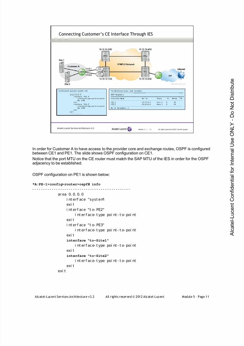
7/21/2019 Services Architecture v3.2 Student Guide Download
http://slidepdf.com/reader/full/services-architecture-v32-student-guide-download 287/429
Alcatel-Lucent Services Architecture v3.2 All rights reserved © 2012 Alcatel-Lucent Module 5 – Page 11
Module 5 | 11 All r ights reserved ©2012 Alcatel-LucentAlcatel-Lucent Services Architecture v3.2
Connecting Customer’s CE Interface Through IES
*A:CE1>confi g>router >ospf# i nfo- - - - - - - - - - - - -- - - - - - - - - - - -- - - - - - - - - - - -- - - - - - - - -
area 0.0.0. 0i nterface "IES_1"
i nterface-t ype poi nt-to-pointmtu 1500
exi ti nterface "IES_2"
i nterface-t ype poi nt-to-pointmtu 1500
exi texi t
- - - - - - - - - - - - -- - - - - - - - - - - -- - - - - - - - - - - -- - - - - - - - -
*A:CE1#show router ospf nei ghbor============================================================================OSPF Neighbor s=============================================================================Interface-Name Rt r Id State Pr i RetxQ TTL- - - - - - - - - - - -- - - - - - - - - - - -- - - - - - - - - - - -- - - - - - - - - - - -- - - - - - - - - - - -- - - - - - - - - - - -- - - - -I ES_1 10.10.10.1 Full 1 0 38I ES_2 10.10.10.1 Full 1 0 34- - - - - - - - - - - -- - - - - - - - - - - -- - - - - - - - - - - -- - - - - - - - - - - -- - - - - - - - - - - -- - - - - - - - - - - -- - - - -No. of Nei ghbors: 2
In order for Customer A to have access to the provider core and exchange routes, OSPF is configuredbetween CE1 and PE1. The slide shows OSPF configuration on CE1.
Notice that the port MTU on the CE router must match the SAP MTU of the IES in order for the OSPFadjacency to be established.
OSPF configuration on PE1 is shown below:
*A:PE-1>config>router>ospf# info
- - - - - - - - - - - - - - - - - - - - - - - - - - - - - - - - - - - - - - - - - - - - - -
ar ea 0. 0. 0. 0
i nt erf ace "syst em"
exi t
i nt er f ace "t o- PE2"
i nt er f ace- t ype poi nt - t o- poi nt
exi t
i nt er f ace "t o- PE3"
i nt er f ace- t ype poi nt - t o- poi nt
exi t
interface "to-Site1"
i nt er f ace- t ype poi nt - t o- poi nt
exi t
interface "to-Site2"
i nt er f ace- t ype poi nt - t o- poi nt
exi t
exi t

7/21/2019 Services Architecture v3.2 Student Guide Download
http://slidepdf.com/reader/full/services-architecture-v32-student-guide-download 288/429
Alcatel-Lucent Services Architecture v3.2 All rights reserved © 2012 Alcatel-Lucent Module 5 – Page 12
Module 5 | 12 All r ights reserved ©2012 Alcatel-LucentAlcatel-Lucent Services Architecture v3.2
Connecting Customer’s CE Interface Through IES (continued)
*A:CE1#show router route-t abl e===============================================================================Route Tabl e (Router: Base)===============================================================================Dest Prefi x Type Proto Age Pref
Next Hop[I nterf ace Name] Metr i c- - - - - - - - - - - - -- - - - - - - - - - - -- - - - - - - - - - - -- - - - - - - - - - -- - - - - - - - - - - -- - - - - - - - - - - -- - - - - - -10. 1. 2. 0/ 27 Remot e OSPF 19h43m26s 10
192.168. 100.2 20010. 1. 3. 0/ 27 Remot e OSPF 19h43m26s 10
192.168. 100.2 20010. 2. 4. 0/ 27 Remot e OSPF 19h43m26s 10
192.168. 100.2 30010. 3. 4. 0/ 27 Remot e OSPF 19h43m26s 10
192.168. 100.2 40010. 10. 10. 1/ 32 Remot e OSPF 19h43m26s 10
192.168. 100.2 10010. 10. 10. 2/ 32 Remot e OSPF 19h43m26s 10
192.168. 100.2 20010. 10. 10. 3/ 32 Remot e OSPF 19h43m26s 10
192.168. 100.2 20010. 10. 10. 4/ 32 Remot e OSPF 19h43m26s 10
192.168. 100.2 30010.10.10.5/32 Local Local 35d01h48m 0
system 0192.168.100. 0/27 Local Local 19h55m06s 0
I ES_1 0192.168.200. 0/27 Local Local 19h54m12s 0
I ES_2 0- - - - - - - - - - - - -- - - - - - - - - - - -- - - - - - - - - - - -- - - - - - - - - - -- - - - - - - - - - - -- - - - - - - - - - - -- - - - - - -No. of Routes: 11
The customer receives the routes from the provider core
The customer is able to receive the routes from the provider core and will be able to access the
Internet via the core network.

7/21/2019 Services Architecture v3.2 Student Guide Download
http://slidepdf.com/reader/full/services-architecture-v32-student-guide-download 289/429
Alcatel-Lucent Services Architecture v3.2 All rights reserved © 2012 Alcatel-Lucent Module 5 – Page 13
Module 5 | 13 All r ights reserved ©2012 Alcatel-LucentAlcatel-Lucent Services Architecture v3.2
Connecting Customer’s CE Interface Through IES (continued)
*A:CE1# pi ng 10.10.10.4 source 192.168.100.1 si ze 1472 count 1PI NG 10.10.10.4 1472 data bytes1480 bytes f rom 10.10. 10.4: i cmp_seq=1 tt l =62 ti me=2. 99ms.
- - - - 10.10.10.4 PINGStat is t i c s - - - -1 packet transmi tt ed, 1 packet r eceived, 0.00% packet loss
round-t ri p mi n = 2.99ms, avg = 2.99ms, max = 2.99ms, st ddev = 0.000ms
Layer 3 service performs fragmentation to accommodate larger packets.
*A:CE1# pi ng 10.10.10.4 source 192.168.100.1 si ze 1473 count 1 do-not-fragment
PI NG 10.10.10.4 1473 data bytesRequest t i med out. i cmp_seq=1.
- - - - 10.10.10.4 PINGStat is t i c s - - - -1 packet t ransmi tt ed, 0 packets r ecei ved, 100% packet loss
*A:CE1# pi ng 10.10.10.4 source 192.168.100.1 si ze 1473 count 1PI NG 10.10.10.4 1473 data bytes1481 bytes f rom 10.10. 10.4: i cmp_seq=1 tt l =62 ti me=3. 02ms.
- - - - 10.10.10.4 PINGStat is t i c s - - - -1 packet transmi tt ed, 1 packet r eceived, 0.00% packet loss
round-t ri p mi n = 3.02ms, avg = 3.02ms, max = 3.02ms, st ddev = 0.000ms
The ping test shown verifies that the customer can reach destinations within the provider core. Since
the CE router system interface has not been advertised through the network (as shown in previous
slide for the OSPF configuration of the CE router), a source address needs to be specified in the ping
because the default behavior of the 7750 SR is to use the system interface as the source address of a
ping destined to a non-directly attached network.
The frame size generated by the ping with size 1472 bytes equals to 1518 bytes ( 1472 + 20 IP header
+ 8 ICMP header + 14 Layer 2 header + 4 VLAN tag). In this case, the ping is successful because the
frame size is less than the SAP MTU.
In the second ping test, the frame size equals 1519 bytes (ping size 1473), which is larger than the
SAP MTU; however, the ping is still successful. The reason is that Layer 3 service performs
fragmentation to accommodate larger packets.
In the third ping test, when the do-not-fragment option is added, the ping is not successful because
fragmentation is not performed. This results in a frame size larger than the SAP MTU.

7/21/2019 Services Architecture v3.2 Student Guide Download
http://slidepdf.com/reader/full/services-architecture-v32-student-guide-download 290/429
Alcatel-Lucent Services Architecture v3.2 All rights reserved © 2012 Alcatel-Lucent Module 5 – Page 14
Module 5 — Layer 3 Services
Section 2 —Layer 3 Service Spoke Termination to Layer 2 VPN

7/21/2019 Services Architecture v3.2 Student Guide Download
http://slidepdf.com/reader/full/services-architecture-v32-student-guide-download 291/429
Alcatel-Lucent Services Architecture v3.2 All rights reserved © 2012 Alcatel-Lucent Module 5 – Page 15
Module 5 | 15 All r ights reserved ©2012 Alcatel-LucentAlcatel-Lucent Services Architecture v3.2
Section Objectives
After successfully completing this section, you will be able to:
Describe the application or use of Layer 3 service spoke
termination to a Layer 2 VPN
Highlight the MTU issues that can arise when configuring a Layer 3
service spoke termination to a Layer 2 VPN service
Describe the steps for configuring IES spoke termination to VPLS
Complete Lab 8 – IES Spoke Termination to a VPLS
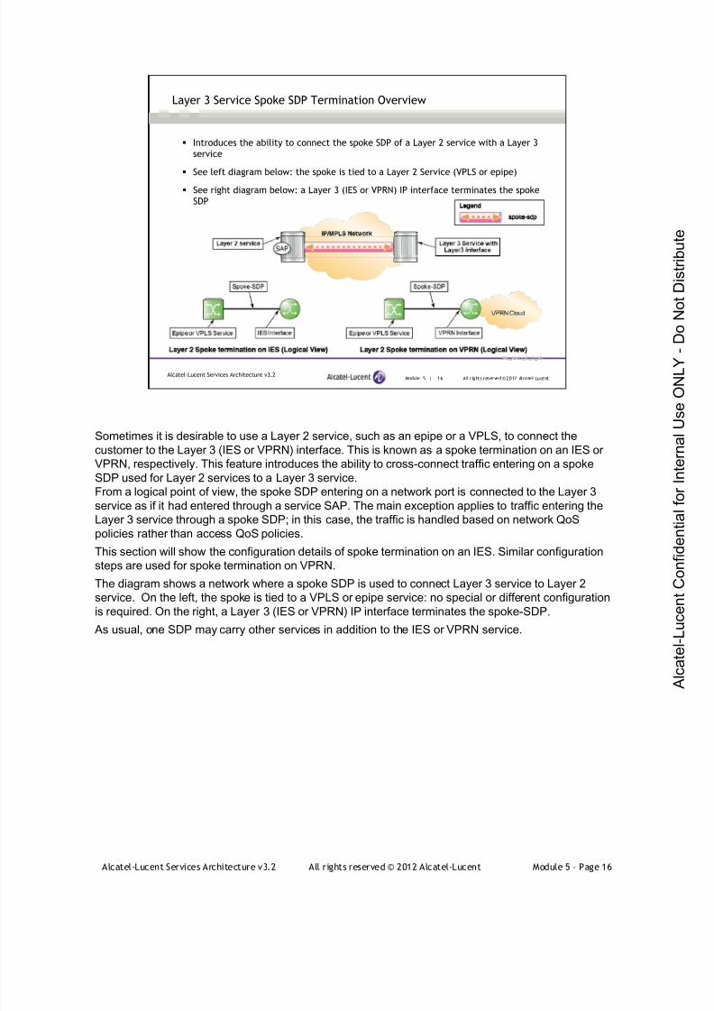
7/21/2019 Services Architecture v3.2 Student Guide Download
http://slidepdf.com/reader/full/services-architecture-v32-student-guide-download 292/429
Alcatel-Lucent Services Architecture v3.2 All rights reserved © 2012 Alcatel-Lucent Module 5 – Page 16
Module 5 | 16 All r ights reserved ©2012 Alcatel-LucentAlcatel-Lucent Services Architecture v3.2
Layer 3 Service Spoke SDP Termination Overview
Introduces the ability to connect the spoke SDP of a Layer 2 service with a Layer 3
service
See left diagram below: the spoke is tied to a Layer 2 Service (VPLS or epipe)
See right diagram below: a Layer 3 (IES or VPRN) IP interface terminates the spoke
SDP
Sometimes it is desirable to use a Layer 2 service, such as an epipe or a VPLS, to connect the
customer to the Layer 3 (IES or VPRN) interface. This is known as a spoke termination on an IES or
VPRN, respectively. This feature introduces the ability to cross-connect traffic entering on a spoke
SDP used for Layer 2 services to a Layer 3 service.
From a logical point of view, the spoke SDP entering on a network port is connected to the Layer 3
service as if it had entered through a service SAP. The main exception applies to traffic entering the
Layer 3 service through a spoke SDP; in this case, the traffic is handled based on network QoS
policies rather than access QoS policies.
This section will show the configuration details of spoke termination on an IES. Similar configuration
steps are used for spoke termination on VPRN.
The diagram shows a network where a spoke SDP is used to connect Layer 3 service to Layer 2
service. On the left, the spoke is tied to a VPLS or epipe service: no special or different configuration
is required. On the right, a Layer 3 (IES or VPRN) IP interface terminates the spoke-SDP.
As usual, one SDP may carry other services in addition to the IES or VPRN service.
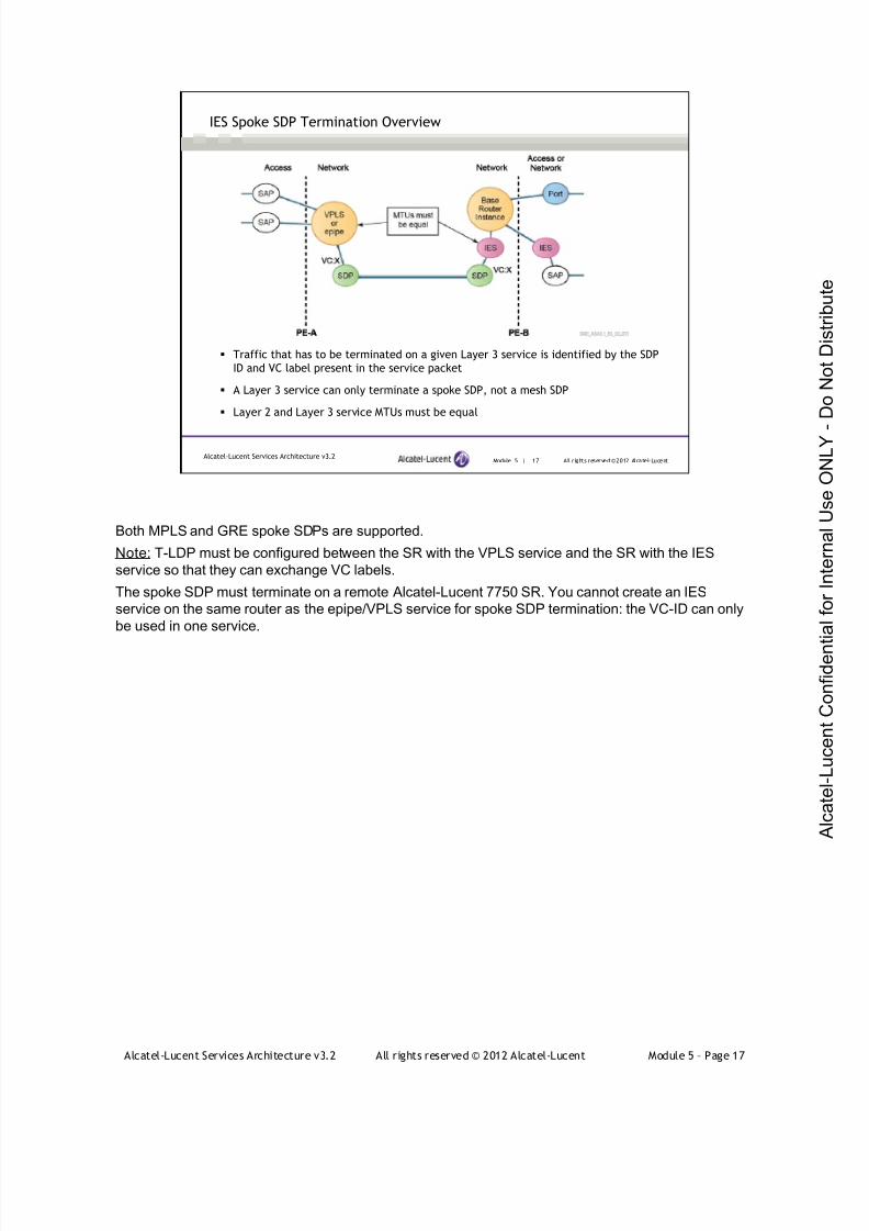
7/21/2019 Services Architecture v3.2 Student Guide Download
http://slidepdf.com/reader/full/services-architecture-v32-student-guide-download 293/429
Alcatel-Lucent Services Architecture v3.2 All rights reserved © 2012 Alcatel-Lucent Module 5 – Page 17
Module 5 | 17 All r ights reserved ©2012 Alcatel-LucentAlcatel-Lucent Services Architecture v3.2
IES Spoke SDP Termination Overview
Traffic that has to be terminated on a given Layer 3 service is identified by the SDP
ID and VC label present in the service packet
A Layer 3 service can only terminate a spoke SDP, not a mesh SDP
Layer 2 and Layer 3 service MTUs must be equal
Both MPLS and GRE spoke SDPs are supported.
Note: T-LDP must be configured between the SR with the VPLS service and the SR with the IES
service so that they can exchange VC labels.
The spoke SDP must terminate on a remote Alcatel-Lucent 7750 SR. You cannot create an IES
service on the same router as the epipe/VPLS service for spoke SDP termination: the VC-ID can only
be used in one service.
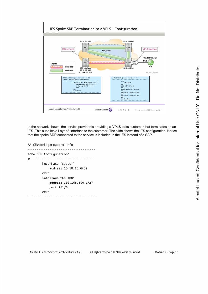
7/21/2019 Services Architecture v3.2 Student Guide Download
http://slidepdf.com/reader/full/services-architecture-v32-student-guide-download 294/429
Alcatel-Lucent Services Architecture v3.2 All rights reserved © 2012 Alcatel-Lucent Module 5 – Page 18
Module 5 | 18 All r ights reserved ©2012 Alcatel-LucentAlcatel-Lucent Services Architecture v3.2
IES Spoke SDP Termination to a VPLS - Configuration
*A:PE-1#conf i gure servi ce i es 100*A:PE-1>confi g>servi ce>i es#i nfo- - - - - - - - - - - - - - - - - - - - - - - - - - - - - - - - - - - - - - - - - - - - - -
interface "To_VPLS_1000" create
address 192.168.100.2/27
spoke-sdp 2:100 create
exi texi tno shut down
- - - - - - - - - - -- - - - - - - - - - - -- - - - - - - - - - - -- - - - - - - - - -
*A:PE-2>confi g>servi ce>vpl s# i nfo- - - - - - - - - - - -- - - - - - - - - - - -- - - - - - - - - - - -- - - - - - - - - -
st pshut down
exi tsap 1/ 1/4 createexi tspoke-sdp 1:100 create
exi tmesh-sdp 3:1000 creat eexi tmesh-sdp 4:1000 creat eexi tno shut down
- - - - - - - - - - - -- - - - - - - - - - - -- - - - - - - - - - - -- - - - - - - - - -
In the network shown, the service provider is providing a VPLS to its customer that terminates on an
IES. This supplies a Layer 3 interface to the customer. The slide shows the IES configuration. Notice
that the spoke SDP connected to the service is included in the IES instead of a SAP.
*A: CE>conf i g>r out er# i nf o
- - - - - - - - - - - - - - - - - - - - - - - - - - - - - - - - - - - - -
echo "I P Conf i gur ati on"#- - - - - - - - - - - - - - - - - - - - - - - - - - - - - - - - - - - -
i nt erf ace "syst em"
addr ess 10. 10. 10. 6/ 32
exi t
interface "to-IES"
address 192.168.100.1/27
port 1/1/3
exi t
- - - - - - - - - - - - - - - - - - - - - - - - - - - - - - - - - - - - -
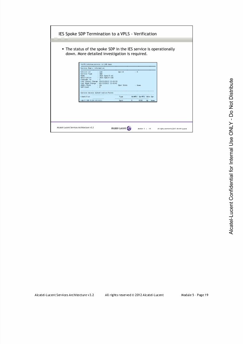
7/21/2019 Services Architecture v3.2 Student Guide Download
http://slidepdf.com/reader/full/services-architecture-v32-student-guide-download 295/429
Alcatel-Lucent Services Architecture v3.2 All rights reserved © 2012 Alcatel-Lucent Module 5 – Page 19
Module 5 | 19 All r ights reserved ©2012 Alcatel-LucentAlcatel-Lucent Services Architecture v3.2
IES Spoke SDP Termination to a VPLS - Verification
The status of the spoke SDP in the IES service is operationally
down. More detailed investigation is required.
*A:PE-1#show service i d 100 base===============================================================================Service Basi c I nformati on===============================================================================Service I d : 100 Vpn Id : 0Service Type : IES
Name : (Not Speci fi ed)Descri pti on : (Not Specif i ed)Customer I d : 1Last Status Change: 03/12/2012 11: 43:33Last Mgmt Change : 03/ 12/2012 11: 43:42Admi n State : Up Oper State : Down
SAP Count : 0
- - - - - - - - - - - - -- - - - - - - - - - - -- - - - - - - - - - - -- - - - - - - - - - - -- - - - - - - - - - - -- - - - - - - - - - - -- - - - - -Service Access &Desti nati on Points- - - - - - - - - - - - -- - - - - - - - - - - -- - - - - - - - - - - -- - - - - - - - - - - -- - - - - - - - - - - -- - - - - - - - - - - -- - - - - -I denti fi er Type AdmMTU OprMTU Adm Opr- - - - - - - - - - - - -- - - - - - - - - - - -- - - - - - - - - - - -- - - - - - - - - - - -- - - - - - - - - - - -- - - - - - - - - - - -- - - - - -s dp: 2 : 100 S( 10. 1 0. 1 0. 2 ) Spok 0 9190 Up Down
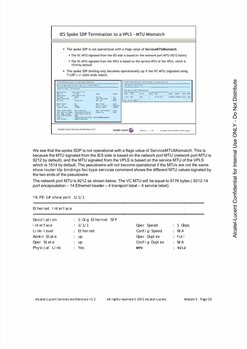
7/21/2019 Services Architecture v3.2 Student Guide Download
http://slidepdf.com/reader/full/services-architecture-v32-student-guide-download 296/429
Alcatel-Lucent Services Architecture v3.2 All rights reserved © 2012 Alcatel-Lucent Module 5 – Page 20
Module 5 | 20 All r ights reserved ©2012 Alcatel-LucentAlcatel-Lucent Services Architecture v3.2
IES Spoke SDP Termination to a VPLS - MTU Mismatch
The spoke SDP is not operational with a flags value of ServiceMTUMismatch
The VC-MTU signaled from the IES side is based on the network port MTU (9212 bytes)
The VC-MTU signaled from the VPLS is based on the service MTU of the VPLS, which is1514 by default
The spoke SDP binding only becomes operationally up if the VC-MTU (signaled using
T-LDP ) on both ends match.
*A:PE-1#show service i d 100 sdp 2:100 detail=========================================================================Servi ce Desti nati on Point (Sdp I d : 2:100) Detai l s=========================================================================Sdp I d 2:100 -(10.10.10.2)
- - - - - - - - - - - - - - - -- - - - - - - - - - - - - - - - -- - - - - - - - - - - - - - - - - -- - - - - - - - - - - - - - - - -- - - - -Descri pti on : (Not Specif i ed)SDP I d : 2:100 Type : SpokeSpo ke De sc r : ( N ot S pe ci f i ed)VC Type : Ether VC Tag : n/aAdmi n Path MTU : 0 Oper Path MTU : 9190Far End : 10.10.10. 2 Del i very : MPLS
Admi n State : Up Oper State : Down
Acc t. Pol : None Col l e ct St at s : Di s abl edI ngress Label : 131064 Egress Label : 131062…Admin Control Word : Not Preferred Oper ControlWord : FalseLast Stat us Change : 01/30/2012 16:55:09 Signal i ng : TLDPLast Mgmt Change : 03/12/ 2012 11:43: 42Class Fwdi ng Stat e : DownFlags : PWPeerFault StatusBits ServiceMTUMismatch
Peer Pw Bit s : pwNotForwarding…
*A:PE-1#showrouter l dp b indi ngs f ec-type servi ces==============================================================================LDP LSR ID: 10.10. 10.1==============================================================================…LDP Servi ce FEC 128 Bindi ngs============================================================================== Type VCId SvcI d SDPI d Peer I ngLbl EgrLbl LMTU RMTU- - - - - - - - - - - - - - - -- - - - - - - - - - - - - - - - -- - - - - - - - - - - - - - - - - -- - - - - - - - - - - - - - - - -- - - - - - - - - -I - E th 1 00 10 0 2 10 .10 .10 .2 1 31 06 4U 1 310 62 D 9176 1500
- - - - - - - - - - - - - - - -- - - - - - - - - - - - - - - - -- - - - - - - - - - - - - - - - - -- - - - - - - - - - - - - - - - -- - - - - - - - - -No. of VC Labels: 1
We see that the spoke SDP is not operational with a flags value of ServiceMTUMismatch. This is
because the MTU signaled from the IES side is based on the network port MTU (network port MTU is
9212 by default), and the MTU signaled from the VPLS is based on the service MTU of the VPLS
which is 1514 by default. The pseudowire will not become operational if the MTUs are not the same.
show router ldp bindings fec-type services command shows the different MTU values signaled by
the two ends of the pseudowire.
The network port MTU is 9212 as shown below. The VC MTU will be equal to 9176 bytes ( 9212-14
port encapsulation – 14 Ethernet header – 4 transport label – 4 service label).
*A: PE- 1# show port 1/ 1/ 1
===============================================================================
Et her net I nt er f ace
===============================================================================
Descr i pt i on : 1- Gi g Et hernet SFP
I nt er f ace : 1/ 1/ 1 Oper Speed : 1 Gbps
Li nk- l evel : Et her net Conf i g Speed : N/ A
Admi n St at e : up Oper Dupl ex : f ul l
Oper St at e : up Conf i g Dupl ex : N/ A
Physi cal Li nk : Yes MTU : 9212
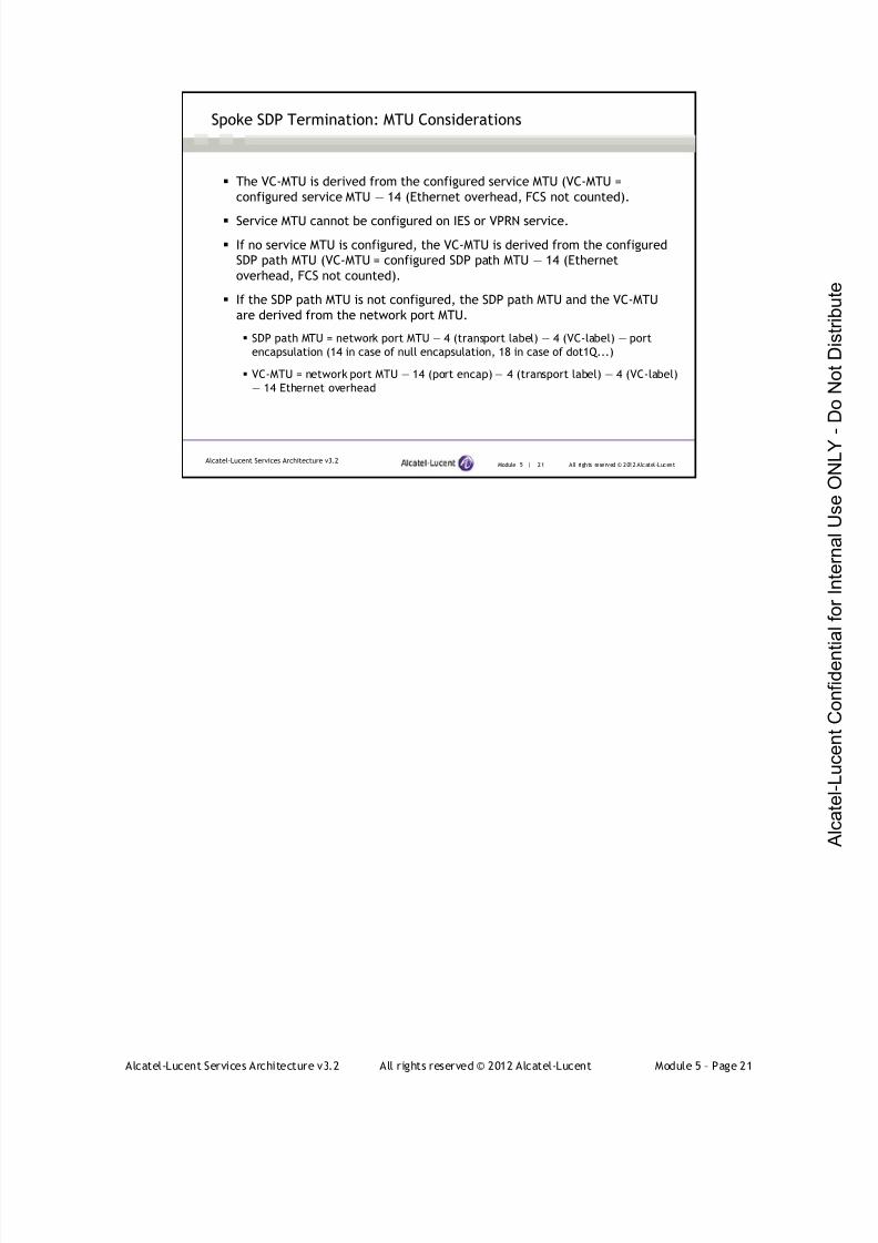
7/21/2019 Services Architecture v3.2 Student Guide Download
http://slidepdf.com/reader/full/services-architecture-v32-student-guide-download 297/429
Alcatel-Lucent Services Architecture v3.2 All rights reserved © 2012 Alcatel-Lucent Module 5 – Page 21
Module 5 | 21 All rights reserved © 2012 Alcatel-LucentAlcatel-Lucent Services Architecture v3.2
The VC-MTU is derived from the configured service MTU (VC-MTU =
configured service MTU — 14 (Ethernet overhead, FCS not counted).
Service MTU cannot be configured on IES or VPRN service.
If no service MTU is configured, the VC-MTU is derived from the configured
SDP path MTU (VC-MTU = configured SDP path MTU — 14 (Ethernet
overhead, FCS not counted).
If the SDP path MTU is not configured, the SDP path MTU and the VC-MTU
are derived from the network port MTU.
SDP path MTU = network port MTU — 4 (transport label) — 4 (VC-label) — port
encapsulation (14 in case of null encapsulation, 18 in case of dot1Q...)
VC-MTU = network port MTU — 14 (port encap) — 4 (transport label) — 4 (VC-label)
— 14 Ethernet overhead
Spoke SDP Termination: MTU Considerations
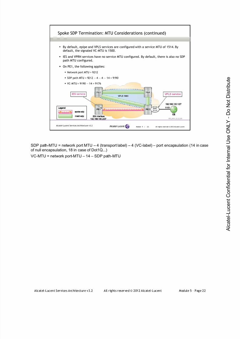
7/21/2019 Services Architecture v3.2 Student Guide Download
http://slidepdf.com/reader/full/services-architecture-v32-student-guide-download 298/429
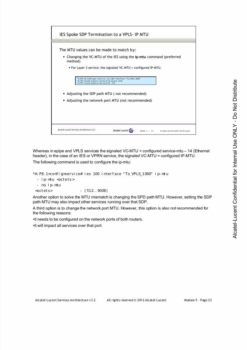
7/21/2019 Services Architecture v3.2 Student Guide Download
http://slidepdf.com/reader/full/services-architecture-v32-student-guide-download 299/429
Alcatel-Lucent Services Architecture v3.2 All rights reserved © 2012 Alcatel-Lucent Module 5 – Page 23
Module 5 | 23 All r ights reserved ©2012 Alcatel-LucentAlcatel-Lucent Services Architecture v3.2
IES Spoke SDP Termination to a VPLS- IP MTU
The MTU values can be made to match by:
Changing the VC-MTU of the IES using the ip-mtu command (preferred
method)
For Layer 3 service: the signaled VC-MTU = configured IP-MTU.
Adjusting the SDP path MTU ( not recommended)
Adjusting the network port MTU (not recommended)
*A:PE-1# conf i gure servi ce i es 100 i nterf ace “To_VPLS_1000"*A: PE-1>conf i g>servi ce>i es>i f # ip-mtu 1500
*A:PE-1>conf i g>servi ce>i es>i f# i nfo
Whereas in epipe and VPLS services the signaled VC-MTU = configured service-mtu – 14 (Ethernet
header), in the case of an IES or VPRN service, the signaled VC-MTU = configured IP-MTU.
The following command is used to configure the ip-mtu:
*A: PE- 1>conf i g>servi ce# i es 100 i nter f ace "To_VPLS_1000" i p- mt u
- i p- mtu <octets>
- no i p- mtu
<oct ets> : [ 512. . 9000]
Another option to solve the MTU mismatch is changing the SPD path MTU. However, setting the SDP
path MTU may also impact other services running over that SDP.
A third option is to change the network port MTU. However, this option is also not recommended for
the following reasons:
•It needs to be configured on the network ports of both routers.
•It will impact all services over that port.

7/21/2019 Services Architecture v3.2 Student Guide Download
http://slidepdf.com/reader/full/services-architecture-v32-student-guide-download 300/429
Alcatel-Lucent Services Architecture v3.2 All rights reserved © 2012 Alcatel-Lucent Module 5 – Page 24
Module 5 | 24 All r ights reserved ©2012 Alcatel-LucentAlcatel-Lucent Services Architecture v3.2
IES Spoke SDP Termination to a VPLS - Verification
*A:PE-1# show service i d 100 base===============================================================================Servi ce Basic I nformati on===============================================================================Service Id : 100 Vpn Id : 0Servi ce Type : IES
Name : (Not Speci fi ed)Descri pti on : (Not Specif i ed)Customer I d : 1Last Status Change: 03/12/2012 11:54: 50Last Mgmt Change : 03/ 12/2012 11: 43:42Admi n State : Up Oper Stat e : Up
SAP Count : 0- - - - - - - - - - -- - - - - - - - - - - -- - - - - - - - - - - -- - - - - - - - - - - -- - - - - - - - - - - - -- - - - - - - - - - - -- - - - - - -Servi ce Access &Desti nati on Poi nts- - - - - - - - - - -- - - - - - - - - - - -- - - - - - - - - - - -- - - - - - - - - - - -- - - - - - - - - - - - -- - - - - - - - - - - -- - - - - - -I denti fi er Type AdmMTU OprMTU Adm Opr- - - - - - - - - - -- - - - - - - - - - - -- - - - - - - - - - - -- - - - - - - - - - - -- - - - - - - - - - - - -- - - - - - - - - - - -- - - - - - -s dp: 2 : 100 S( 10. 1 0. 1 0. 2 ) Spok 0 9190 Up Up
*A:PE-1#show router l dp bindi ngs f ec-type services===============================================================================LDP LSR I D: 10.10.10.1===============================================================================…output omi tt ed===============================================================================LDP Servi ce FEC 128 Bi ndi ngs===============================================================================
Type VCI d SvcI d SDPI d Peer I ngLbl EgrLbl LMTU RMTU- - - - - - - - - - -- - - - - - - - - - - -- - - - - - - - - - - -- - - - - - - - - - - -- - - - - - - - - - - - -- - - - - - - - - - - -- - - - - - -I - Eth 100 100 2 10.10.10.2 131064U 131062S 1500 1500
The spoke SDP binding and IES are operationally up
*A:PE-2# show service id 1000 base
===============================================================================
Servi ce Basi c I nf ormat i on
===============================================================================
Ser vi ce I d : 1000 Vpn I d : 0
Servi ce Type : VPLS
…
Admi n St ate : Up Oper St ate : UpMTU : 1514 Def . Mesh VC I d : 1000
SAP Count : 1 SDP Bi nd Count : 4
Snd Fl ush on Fai l : Di sabl ed Host Conn Ver i f y : Di sabl ed
Propagate MacFl ush: Di sabl ed Per Svc Hashi ng : Di sabl ed
Def . Gat eway I P : None
Def . Gat eway MAC : None
- - - - - - - - - - - - - - - - - - - - - - - - - - - - - - - - - - - - - - - - - - - - - - - - - - - - - - - - - - - - - - - - - - - - - - - - - - - - - - -
Servi ce Access & Dest i nat i on Poi nts
- - - - - - - - - - - - - - - - - - - - - - - - - - - - - - - - - - - - - - - - - - - - - - - - - - - - - - - - - - - - - - - - - - - - - - - - - - - - - - -
I dent i f i er Type AdmMTU OprMTU Adm Opr
- - - - - - - - - - - - - - - - - - - - - - - - - - - - - - - - - - - - - - - - - - - - - - - - - - - - - - - - - - - - - - - - - - - - - - - - - - - - - - -
sap: 1/ 1/ 4 nul l 1514 1514 Up Up
sdp:1:100 S(10.10.10.1) Spok 0 9190 Up Upsdp: 3: 1000 M( 10. 10. 10. 3) Mesh 0 9190 Up Up
sdp: 4: 1000 M( 10. 10. 10. 4) Mesh 0 9190 Up Up
===============================================================================

7/21/2019 Services Architecture v3.2 Student Guide Download
http://slidepdf.com/reader/full/services-architecture-v32-student-guide-download 301/429
Alcatel-Lucent Services Architecture v3.2 All rights reserved © 2012 Alcatel-Lucent Module 5 – Page 25
Module 5 | 25 All r ights reserved ©2012 Alcatel-LucentAlcatel-Lucent Services Architecture v3.2
IES Spoke SDP Termination to a VPLS – Connectivity Verification
The CE router can now ping the IES interface
The CE router ARP cache has the MAC address of the PE router with the IES
interface
*A:CE# ping 192. 168. 100. 2 count 1PING 192. 168. 100. 2 56 data bytes64 bytes f rom 192. 168. 100. 2: i cmp_seq=1 t tl =64 ti me=3.64ms.
- - - - 1 92 .16 8.1 00 .2 P I NG S tat i s t i cs - - - -1 packet transmitted, 1 packet received, 0.00% packet loss
round-t ri p mi n = 3.64ms, avg = 3.64ms, max = 3.64ms, stddev = 0.000ms
*A:CE# showr outer arp===========================================================ARP Table ( Router : Base)===========================================================I P Address MAC Address Expir y Type I nter face- - - - - - - - - - - - - -- - - - - - - - - - - - - - - - - -- - - - - - - - - - - - - - - - -- - - - - - - - - -192.168.100.1 60:25:01:01:00:03 00h00m00s Oth[I ] to- I ES192.168.100.2 60:20:ff:00:00:00 03h59m54s Dyn[I ] to- I ES
*A:PE-2#showservice i d 1000 fdb detai l===============================================================================Forwardi ng Database, Servi ce 1000===============================================================================ServId MAC Source-I dentif i er Type Last Change
Age- - - - - - - - - - - - - - - -- - - - - - - - - - - - - - - - -- - - - - - - - - - - - - - - - - -- - - - - - - - - - - - - - - - -- - - - - - - - - - -1000 60:20:f f :00: 00: 00 sdp:1:100 L/ 1005 03/14/2012 14:19:06
1000 60:25:01:01:00:03 sap:1/1/ 4 L/ 0 03/14/2012 14:36:09
When traffic is sent from the CE router, it enters the SAP of the VPLS on PE2. Traffic is passed to
PE1 using the spoke SDP between PE2 and PE1. From PE1 traffic can be sent to other routers as an
IP packet using the IGP.
The ARP table of the CE router has one dynamically learned entry for the gateway address. However,
because the gateway address is an IES interface on a spoke SDP, the MAC address supplied to the
CE router is the chassis MAC of PE1.
The VPLS learns two MAC addresses. The first address is the MAC of the CE router, which it learnsfrom the SAP. The second MAC address is PE1 chassis MAC address for the IES interface.
*A:PE-1# show chassis
===============================================================================
Chassi s I nf ormati on
===============================================================================
Name : PE-1
…
Base MAC address : 60:20:ff:00:00:00
*A:CE# show router interface "to-IES" detail
===============================================================================
I nterf ace
- - - - - - - - - - - - - - - - - - - - - - - - - - - - - - - - - - - - - - - - - - - - - - - - - - - - - - - - - - - - - - - - - - - - - - - - - - - - - - -
I f Name : to-IES
Admi n State : Up Oper ( v4/ v6) : Up/ Down
Protocol s : None
I P Addr / mask : 192.168.100.1/27 Addr ess Type : Pr i mary
I GP I nhi bi t : Di sabl ed Br oadcast Addr ess : Host- ones
- - - - - - - - - - - - - - - - - - - - - - - - - - - - - - - - - - - - - - - - - - - - - - - - - - - - - - - - - - - - - - - - - - - - - - - - - - - - - - -
…
MAC Address : 60:25:01:01:00:03 Ar p Ti meout : 14400
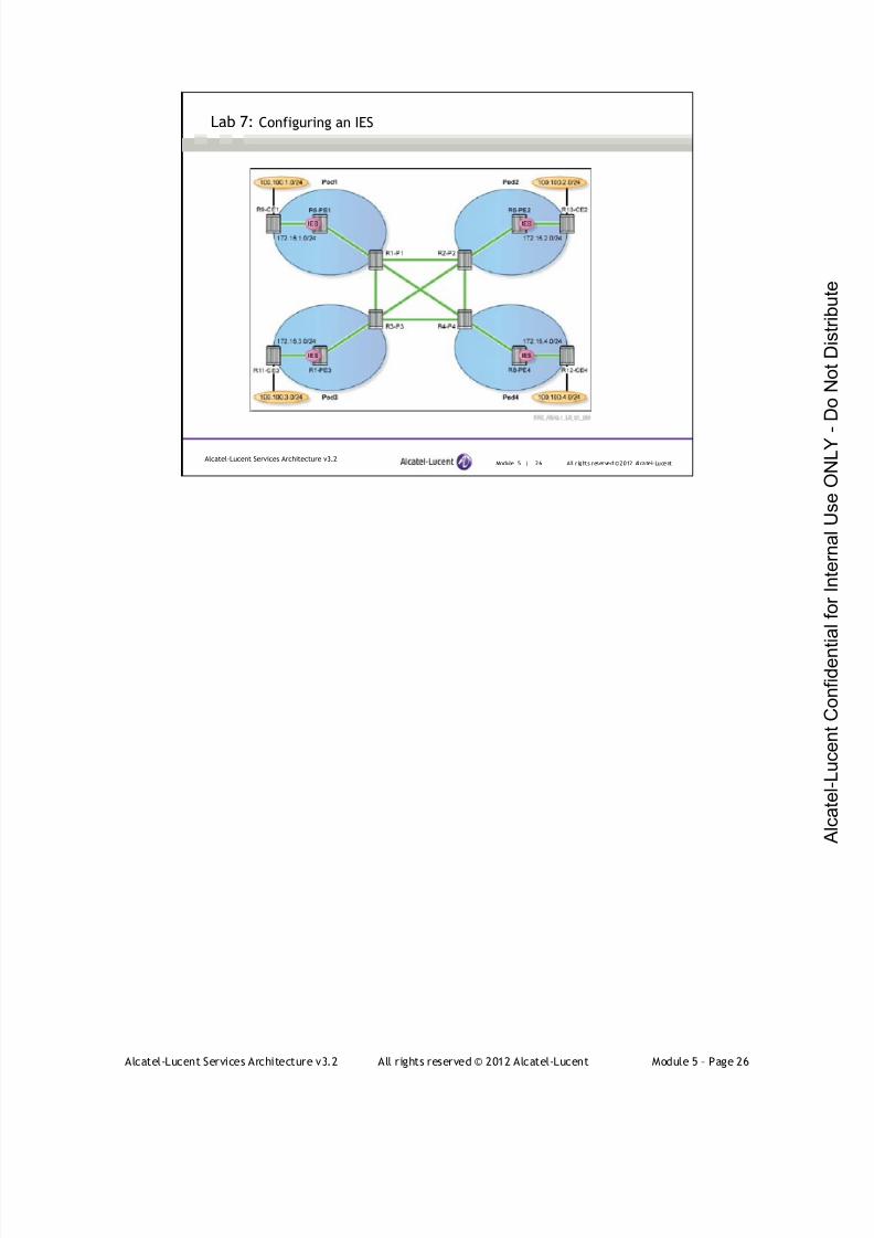
7/21/2019 Services Architecture v3.2 Student Guide Download
http://slidepdf.com/reader/full/services-architecture-v32-student-guide-download 302/429
Alcatel-Lucent Services Architecture v3.2 All rights reserved © 2012 Alcatel-Lucent Module 5 – Page 26
Module 5 | 26 All r ights reserved ©2012 Alcatel-LucentAlcatel-Lucent Services Architecture v3.2
Lab 7: Configuring an IES
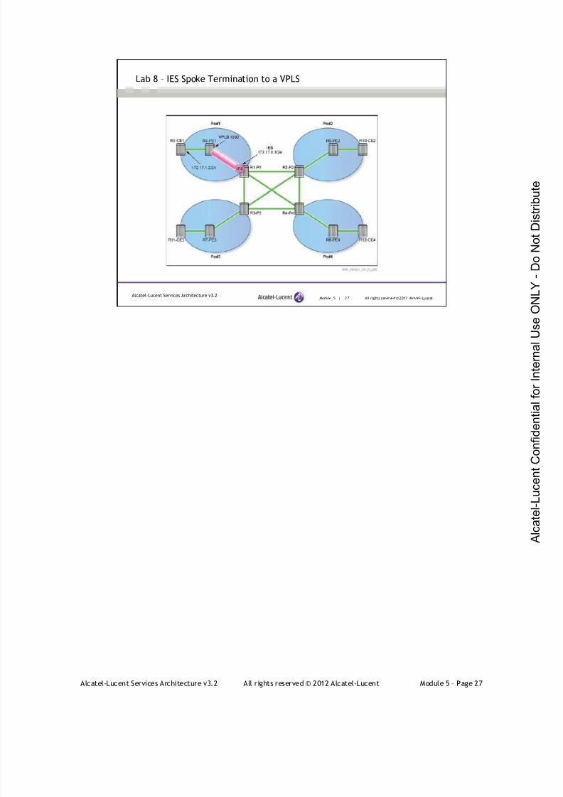
7/21/2019 Services Architecture v3.2 Student Guide Download
http://slidepdf.com/reader/full/services-architecture-v32-student-guide-download 303/429
Alcatel-Lucent Services Architecture v3.2 All rights reserved © 2012 Alcatel-Lucent Module 5 – Page 27
Module 5 | 27 All r ights reserved ©2012 Alcatel-LucentAlcatel-Lucent Services Architecture v3.2
Lab 8 – IES Spoke Termination to a VPLS

7/21/2019 Services Architecture v3.2 Student Guide Download
http://slidepdf.com/reader/full/services-architecture-v32-student-guide-download 304/429
Alcatel-Lucent Services Architecture v3.2 All rights reserved © 2012 Alcatel-Lucent Module 5 – Page 28
Module 5 — Layer 3 Services
Section 3 — VPRN Overview
7/21/2019 Services Architecture v3.2 Student Guide Download
http://slidepdf.com/reader/full/services-architecture-v32-student-guide-download 305/429
Alcatel-Lucent Services Architecture v3.2 All rights reserved © 2012 Alcatel-Lucent Module 5 – Page 29
Module 5 | 29 All rights reserved © 2012 Alcatel-LucentAlcatel-Lucent Services Architecture v3.2
Section Objectives
Define VPRN and explain its features Describe the key mechanisms and features that make up the
VPRN architecture
Explain the implementation of label stack in VPRN
Describe the usage of the VPN routing and forwarding (VRF)
table in VPRN
Describe the distribution of VPRN routing information between
CE-PE and PE-PE routers
Describe data packets forwarding across a service provider
network from a CE router to a remote CE
After successfully completing this section, you will be able to:
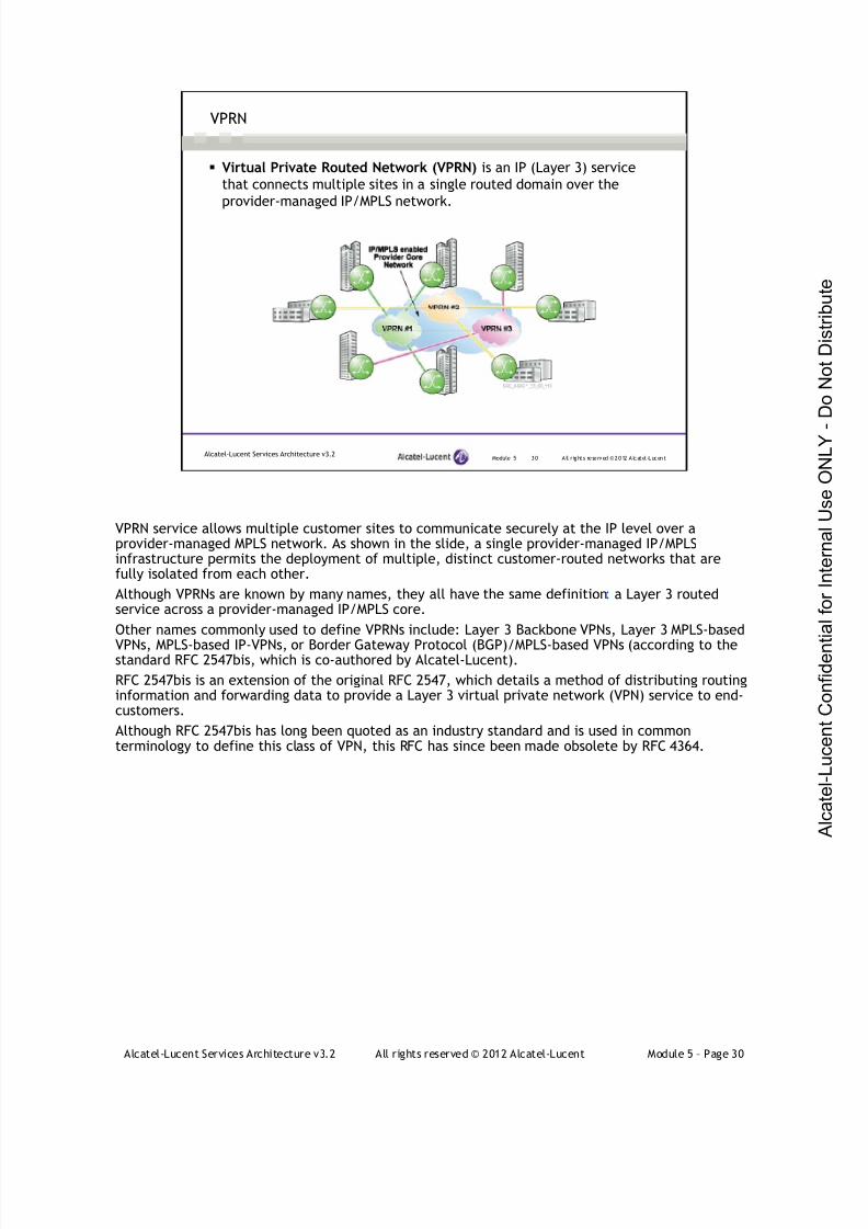
7/21/2019 Services Architecture v3.2 Student Guide Download
http://slidepdf.com/reader/full/services-architecture-v32-student-guide-download 306/429
Alcatel-Lucent Services Architecture v3.2 All rights reserved © 2012 Alcatel-Lucent Module 5 – Page 30
Module 5 | 3 0 All r ight s re served ©2 0 12 A lc atel -LucentAlcatel-Lucent Services Architecture v3.2
VPRN
Virtual Private Routed Network (VPRN) is an IP (Layer 3) service
that connects multiple sites in a single routed domain over the
provider-managed IP/MPLS network.
VPRN service allows multiple customer sites to communicate securely at the IP level over aprovider-managed MPLS network. As shown in the slide, a single provider-managed IP/MPLSinfrastructure permits the deployment of multiple, distinct customer-routed networks that arefully isolated from each other.
Although VPRNs are known by many names, they all have the same definition: a Layer 3 routedservice across a provider-managed IP/MPLS core.
Other names commonly used to define VPRNs include: Layer 3 Backbone VPNs, Layer 3 MPLS-based
VPNs, MPLS-based IP-VPNs, or Border Gateway Protocol (BGP)/MPLS-based VPNs (according to thestandard RFC 2547bis, which is co-authored by Alcatel-Lucent).
RFC 2547bis is an extension of the original RFC 2547, which details a method of distributing routinginformation and forwarding data to provide a Layer 3 virtual private network (VPN) service to end-customers.
Although RFC 2547bis has long been quoted as an industry standard and is used in commonterminology to define this class of VPN, this RFC has since been made obsolete by RFC 4364.
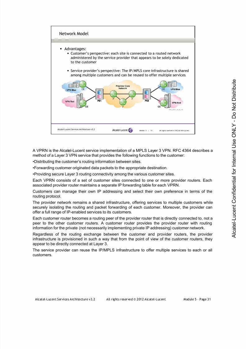
7/21/2019 Services Architecture v3.2 Student Guide Download
http://slidepdf.com/reader/full/services-architecture-v32-student-guide-download 307/429
Alcatel-Lucent Services Architecture v3.2 All rights reserved © 2012 Alcatel-Lucent Module 5 – Page 31
A VPRN is the Alcatel-Lucent service implementation of a MPLS Layer 3 VPN. RFC 4364 describes a
method of a Layer 3 VPN service that provides the following functions to the customer:
•Distributing the customer’s routing information between sites.
•Forwarding customer originated data packets to the appropriate destination.
•Providing secure Layer 3 routing connectivity among the various customer sites.
Each VPRN consists of a set of customer sites connected to one or more provider routers. Each
associated provider router maintains a separate IP forwarding table for each VPRN.
Customers can manage their own IP addressing and select their own preference in terms of the
routing protocol.
The provider network remains a shared infrastructure, offering services to multiple customers while
securely isolating the routing and packet forwarding of each customer. Moreover, the provider can
offer a full range of IP-enabled services to its customers.
Each customer router becomes a routing peer of the provider router that is directly connected to, not a
peer to the other customer routers. A customer router provides the provider router with routing
information for the private (not necessarily implementing private IP addressing) customer network.
Regardless of the routing exchange between the customer and provider routers, the provider
infrastructure is provisioned in such a way that from the point of view of the customer routers, they
appear to be directly connected at Layer 3.The service provider can reuse the IP/MPLS infrastructure to offer multiple services to each or all
customers.
Module 5 | 31 All rights reserved © 2012 Alcatel-LucentAlcatel-Lucent Services Architecture v3.2
Network Model
Advantages: Customer’s perspective: each site is connected to a routed network
administered by the service provider that appears to be solely dedicated
to the customer
Service provider’s perspective: The IP/MPLS core infrastructure is shared
among multiple customers and can be reused to offer multiple services
7/21/2019 Services Architecture v3.2 Student Guide Download
http://slidepdf.com/reader/full/services-architecture-v32-student-guide-download 308/429
Alcatel-Lucent Services Architecture v3.2 All rights reserved © 2012 Alcatel-Lucent Module 5 – Page 32
VPRNs take advantage of the dynamics of IP routing protocols, supporting site additions or removal of
the VPN using the same infrastructure.
This type of VPN invokes label stacking with a top label that allows traffic received from a customer to
transit the interior gateway protocol (IGP) service provider cloud and a bottom label that directs the
traffic to the appropriate outgoing interface or service towards the final destination of the customer
network.
An additional feature of the VPRN includes the ability to support any-to-any IP-only connectivity,providing connectivity among any number of customer sites.
Module 5 | 32 All rights reserved © 2012 Alcatel-LucentAlcatel-Lucent Services Architecture v3.2
VPRN Features
VPRN site additions or removals can be accomplished with
minimal additional configuration
VPRN utilizes MPLS label stacking
The outer label allows traffic to transit across the MPLSnetwork.
The inner label determines the VPRN
Provides connectivity among any number of customer sites
Provides customer routers with transparent IP connectivity
without knowledge of the core router
7/21/2019 Services Architecture v3.2 Student Guide Download
http://slidepdf.com/reader/full/services-architecture-v32-student-guide-download 309/429
Alcatel-Lucent Services Architecture v3.2 All rights reserved © 2012 Alcatel-Lucent Module 5 – Page 33
There are many benefits to be gained by implementing a Layer 3 VPRN service, such as:
• Routing at customer sites can be simplified as the provider is managing the routed infrastructure.
• Some sites can achieve full connectivity with only a default route.
• The entire infrastructure can be provider-managed and provider-maintained.
Redundancy and resiliency are provided by the service provider’s infrastructure, and any architectural
benefits designed in the core can be leveraged by the customer.
Privacy is maintained by the isolation of each customer network and routing topology, which separates
routes into logical routing tables (VRF). The customer is permitted to use virtually any addressing
hierarchy and structure, independent of the provider’s choice of addressing and the addressing of any
other customer of the provider.
Any type of physical interconnection can be used between the CE and the PE provided that the
routers support the required interface type.
Module 5 | 33 All rights reserved © 2012 Alcatel-LucentAlcatel-Lucent Services Architecture v3.2
VPRN Features (continued)
Simplifies the routing topology at customer sites
The service provider manages the core network and the customer
routes
Customers receive the redundancy benefits designed in the
provider core
Layer 2 is independent — allows different Layer 2 connectivity at
customer sites
Allows the usage of overlapping private IP address space among
different customers
Different sites belonging to same customer can use different IP
subnets
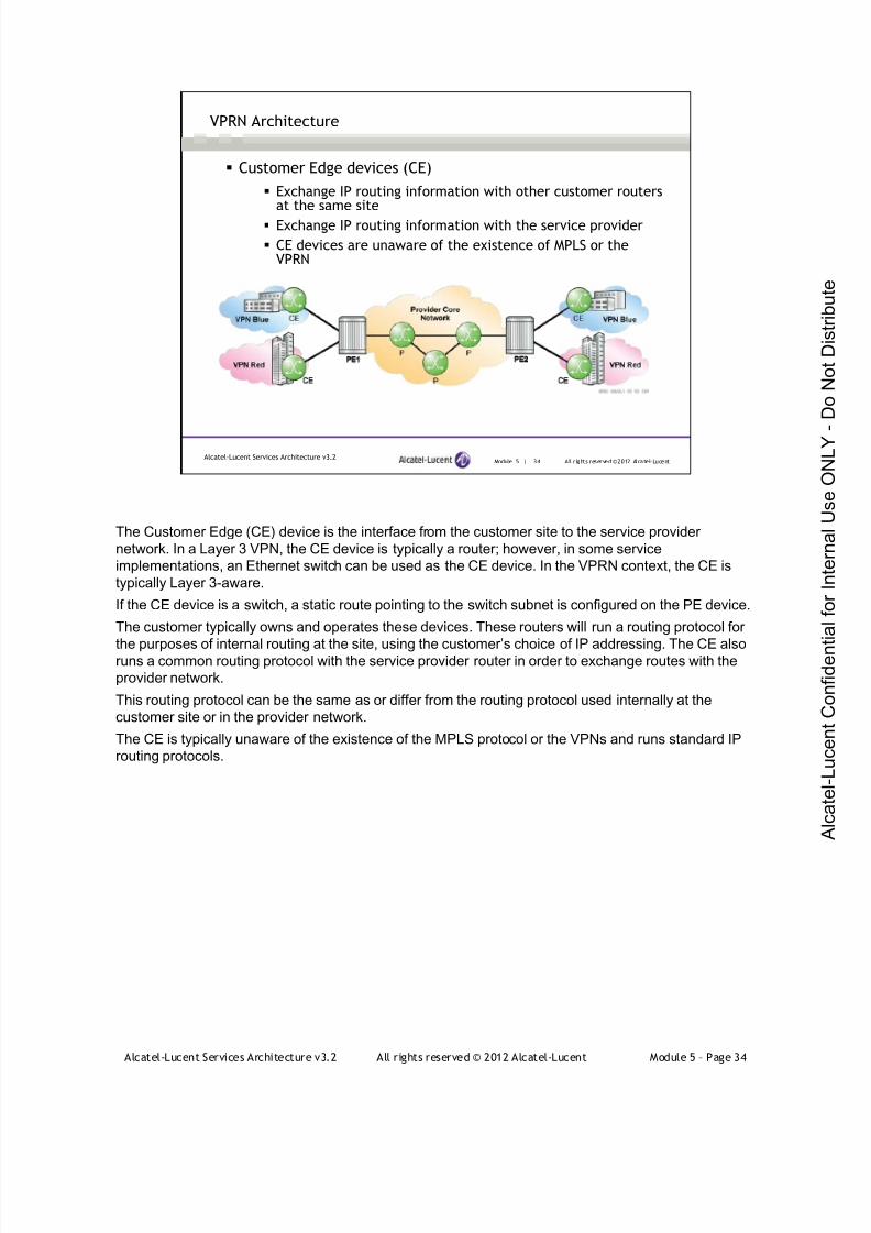
7/21/2019 Services Architecture v3.2 Student Guide Download
http://slidepdf.com/reader/full/services-architecture-v32-student-guide-download 310/429
Alcatel-Lucent Services Architecture v3.2 All rights reserved © 2012 Alcatel-Lucent Module 5 – Page 34
Module 5 | 34 All r ights reserved ©2012 Alcatel-LucentAlcatel-Lucent Services Architecture v3.2
VPRN Architecture
Customer Edge devices (CE)
Exchange IP routing information with other customer routersat the same site
Exchange IP routing information with the service provider
CE devices are unaware of the existence of MPLS or theVPRN
The Customer Edge (CE) device is the interface from the customer site to the service provider
network. In a Layer 3 VPN, the CE device is typically a router; however, in some service
implementations, an Ethernet switch can be used as the CE device. In the VPRN context, the CE is
typically Layer 3-aware.
If the CE device is a switch, a static route pointing to the switch subnet is configured on the PE device.
The customer typically owns and operates these devices. These routers will run a routing protocol for
the purposes of internal routing at the site, using the customer’s choice of IP addressing. The CE alsoruns a common routing protocol with the service provider router in order to exchange routes with the
provider network.
This routing protocol can be the same as or differ from the routing protocol used internally at the
customer site or in the provider network.
The CE is typically unaware of the existence of the MPLS protocol or the VPNs and runs standard IP
routing protocols.
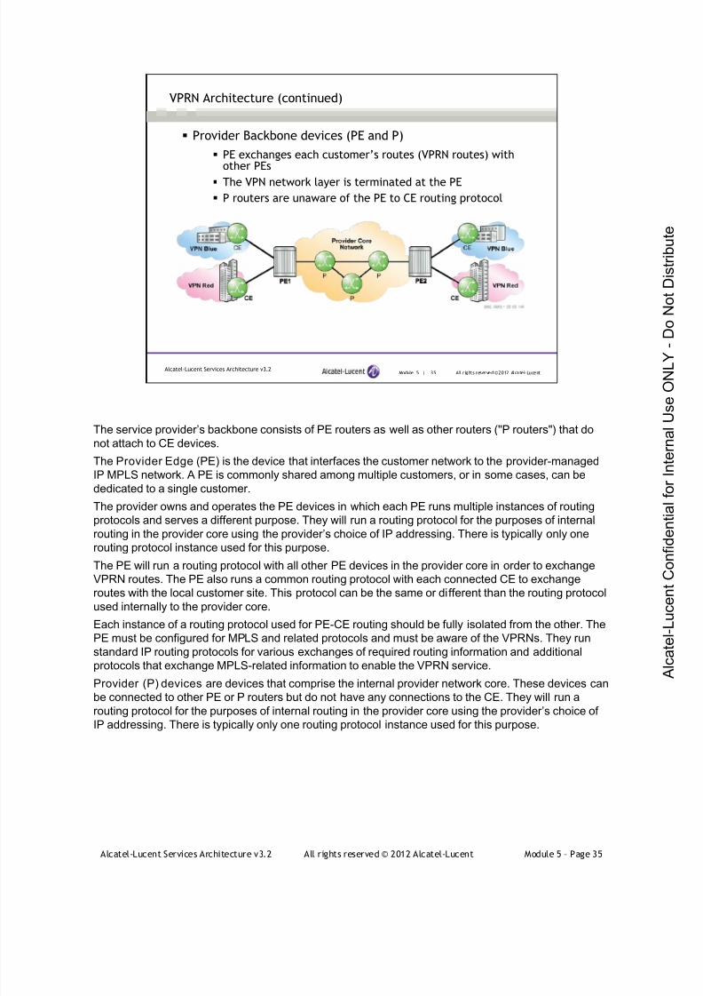
7/21/2019 Services Architecture v3.2 Student Guide Download
http://slidepdf.com/reader/full/services-architecture-v32-student-guide-download 311/429
Alcatel-Lucent Services Architecture v3.2 All rights reserved © 2012 Alcatel-Lucent Module 5 – Page 35
Module 5 | 35 All r ights reserved ©2012 Alcatel-LucentAlcatel-Lucent Services Architecture v3.2
VPRN Architecture (continued)
Provider Backbone devices (PE and P)
PE exchanges each customer’s routes (VPRN routes) withother PEs
The VPN network layer is terminated at the PE
P routers are unaware of the PE to CE routing protocol
The service provider’s backbone consists of PE routers as well as other routers ("P routers") that do
not attach to CE devices.
The Provider Edge (PE) is the device that interfaces the customer network to the provider-managed
IP MPLS network. A PE is commonly shared among multiple customers, or in some cases, can be
dedicated to a single customer.
The provider owns and operates the PE devices in which each PE runs multiple instances of routing
protocols and serves a different purpose. They will run a routing protocol for the purposes of internalrouting in the provider core using the provider’s choice of IP addressing. There is typically only one
routing protocol instance used for this purpose.
The PE will run a routing protocol with all other PE devices in the provider core in order to exchange
VPRN routes. The PE also runs a common routing protocol with each connected CE to exchange
routes with the local customer site. This protocol can be the same or different than the routing protocol
used internally to the provider core.
Each instance of a routing protocol used for PE-CE routing should be fully isolated from the other. The
PE must be configured for MPLS and related protocols and must be aware of the VPRNs. They run
standard IP routing protocols for various exchanges of required routing information and additional
protocols that exchange MPLS-related information to enable the VPRN service.
Provider (P) devices are devices that comprise the internal provider network core. These devices can
be connected to other PE or P routers but do not have any connections to the CE. They will run arouting protocol for the purposes of internal routing in the provider core using the provider’s choice of
IP addressing. There is typically only one routing protocol instance used for this purpose.
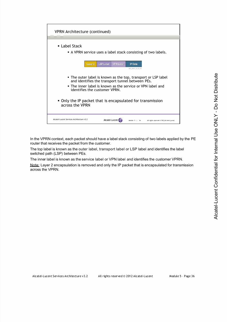
7/21/2019 Services Architecture v3.2 Student Guide Download
http://slidepdf.com/reader/full/services-architecture-v32-student-guide-download 312/429
Alcatel-Lucent Services Architecture v3.2 All rights reserved © 2012 Alcatel-Lucent Module 5 – Page 36
In the VPRN context, each packet should have a label stack consisting of two labels applied by the PE
router that receives the packet from the customer.
The top label is known as the outer label, transport label or LSP label and identifies the label
switched path (LSP) between PEs.
The inner label is known as the service label or VPN label and identifies the customer VPRN.
Note: Layer 2 encapsulation is removed and only the IP packet that is encapsulated for transmission
across the VPRN.
Module 5 | 36 All rights reserved © 2012 Alcatel-LucentAlcatel-Lucent Services Architecture v3.2
Label Stack
A VPRN service uses a label stack consisting of two labels.
The outer label is known as the top, transport or LSP labeland identifies the transport tunnel between PEs.
The inner label is known as the service or VPN label andidentifies the customer VPRN.
Only the IP packet that is encapsulated for transmissionacross the VPRN
VPRN Architecture (continued)
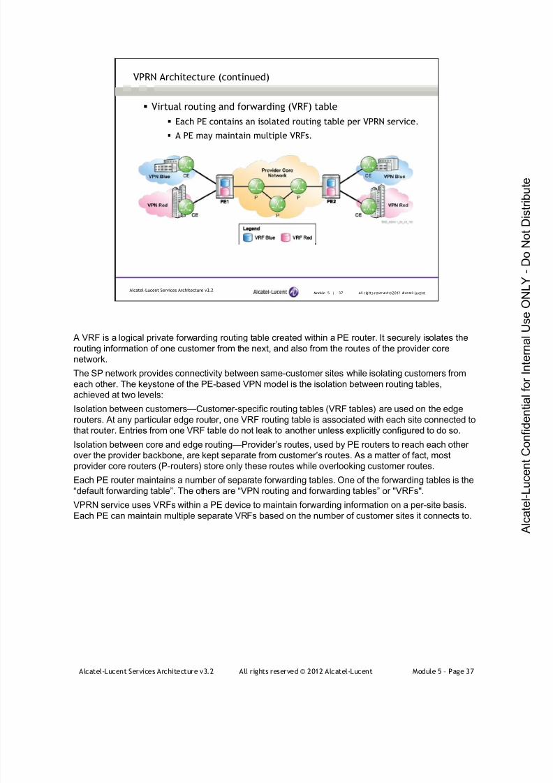
7/21/2019 Services Architecture v3.2 Student Guide Download
http://slidepdf.com/reader/full/services-architecture-v32-student-guide-download 313/429
Alcatel-Lucent Services Architecture v3.2 All rights reserved © 2012 Alcatel-Lucent Module 5 – Page 37
Module 5 | 37 All r ights reserved ©2012 Alcatel-LucentAlcatel-Lucent Services Architecture v3.2
VPRN Architecture (continued)
Virtual routing and forwarding (VRF) table
Each PE contains an isolated routing table per VPRN service.
A PE may maintain multiple VRFs.
A VRF is a logical private forwarding routing table created within a PE router. It securely isolates the
routing information of one customer from the next, and also from the routes of the provider core
network.
The SP network provides connectivity between same-customer sites while isolating customers from
each other. The keystone of the PE-based VPN model is the isolation between routing tables,
achieved at two levels:
Isolation between customers—Customer-specific routing tables (VRF tables) are used on the edgerouters. At any particular edge router, one VRF routing table is associated with each site connected to
that router. Entries from one VRF table do not leak to another unless explicitly configured to do so.
Isolation between core and edge routing—Provider’s routes, used by PE routers to reach each other
over the provider backbone, are kept separate from customer’s routes. As a matter of fact, most
provider core routers (P-routers) store only these routes while overlooking customer routes.
Each PE router maintains a number of separate forwarding tables. One of the forwarding tables is the
“default forwarding table”. The others are “VPN routing and forwarding tables” or "VRFs".
VPRN service uses VRFs within a PE device to maintain forwarding information on a per-site basis.
Each PE can maintain multiple separate VRFs based on the number of customer sites it connects to.

7/21/2019 Services Architecture v3.2 Student Guide Download
http://slidepdf.com/reader/full/services-architecture-v32-student-guide-download 314/429
Alcatel-Lucent Services Architecture v3.2 All rights reserved © 2012 Alcatel-Lucent Module 5 – Page 38
Module 5 | 38 All r ights reserved ©2012 Alcatel-LucentAlcatel-Lucent Services Architecture v3.2
CE to PE Routing Control Plane
CE routes are advertised to the PE and stored in the appropriate VRF
PE to PE Routing Control Plane
CE routes are exchanged between PE routers
PE to CE Routing Control Plane
Propagates remote CE routes within the VRF to the locally attached CE
VPRN Control Plane Routing Functions
The routing control plane function of the VPRN provides the necessary exchange of routing
information between devices that are aware of the VPRN. A PE maintains a specific VRF containing
routes for each VPRN. A CE maintains a standard IP routing table containing routes for the VPRN to
which it belongs.
The customer is running a routing protocol internal to their site. A PE learns the routes of a customer
site from the CE using the routing protocol configured between the CE and the PE. The internal
customer network routing protocol and the CE to PE routing protocol do not have to be identical.
PE maintains the base routing table with internal provider network routes and maintains separate
VRFs for the associated VPRNs. PE devices exchange routes among each other across the provider
core. Isolation must be maintained between the routes received from each customer (per-VRF) and
from provider core routes.
Routes received from each CE might need to be propagated to multiple remote PE devices.
PE to CE route exchange: a policy is required to advertise the remote customer routes to the local CE.
The PE-CE routing protocol, supported on the Alcatel-Lucent 7750, includes static routes, OSPF, RIP,
and BGP
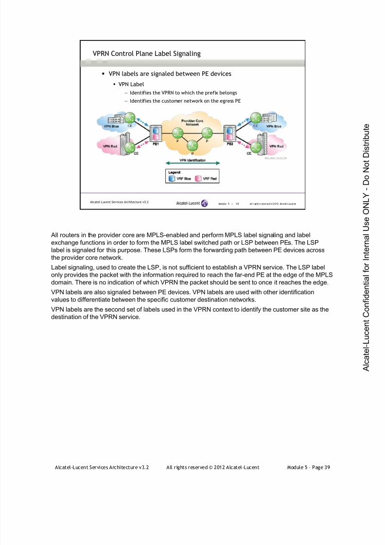
7/21/2019 Services Architecture v3.2 Student Guide Download
http://slidepdf.com/reader/full/services-architecture-v32-student-guide-download 315/429
Alcatel-Lucent Services Architecture v3.2 All rights reserved © 2012 Alcatel-Lucent Module 5 – Page 39
Module 5 | 39 All r ights reserved ©2012 Alcatel-LucentAlcatel-Lucent Services Architecture v3.2
VPRN Control Plane Label Signaling
VPN labels are signaled between PE devices
VPN Label
— Identifies the VPRN to which the prefix belongs— Identifies the customer network on the egress PE
All routers in the provider core are MPLS-enabled and perform MPLS label signaling and label
exchange functions in order to form the MPLS label switched path or LSP between PEs. The LSP
label is signaled for this purpose. These LSPs form the forwarding path between PE devices across
the provider core network.
Label signaling, used to create the LSP, is not sufficient to establish a VPRN service. The LSP label
only provides the packet with the information required to reach the far-end PE at the edge of the MPLS
domain. There is no indication of which VPRN the packet should be sent to once it reaches the edge.
VPN labels are also signaled between PE devices. VPN labels are used with other identification
values to differentiate between the specific customer destination networks.
VPN labels are the second set of labels used in the VPRN context to identify the customer site as the
destination of the VPRN service.
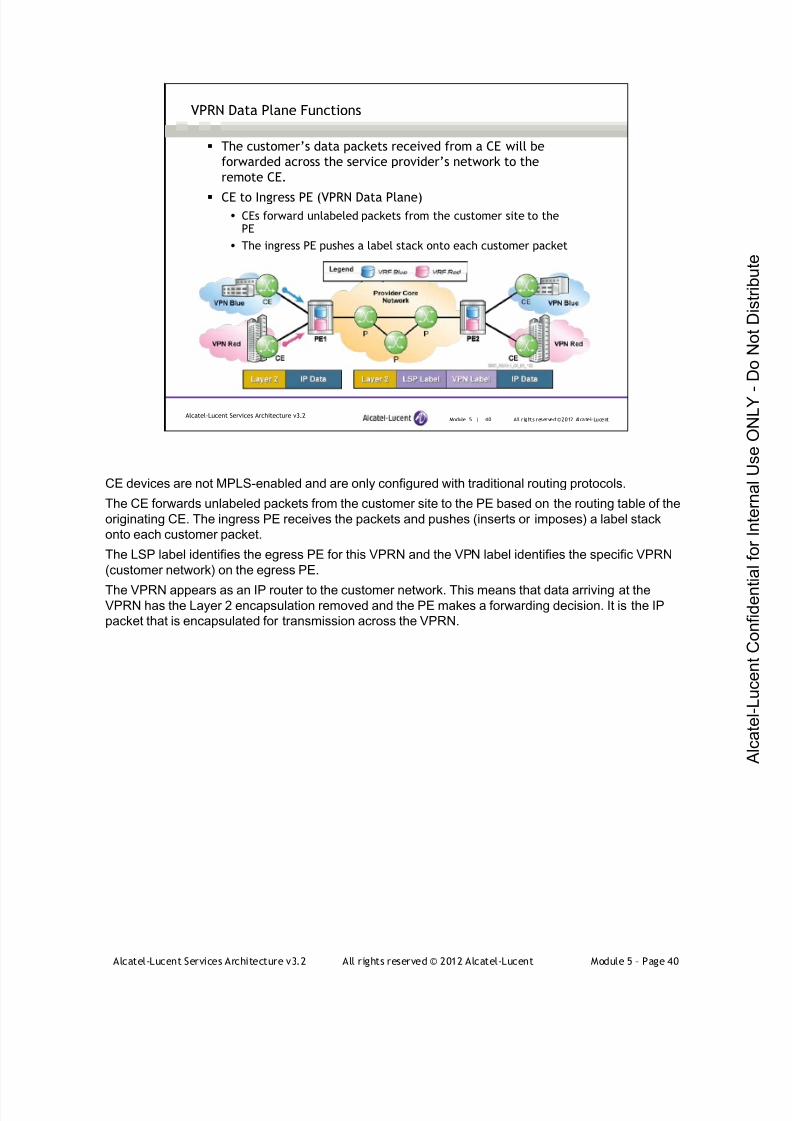
7/21/2019 Services Architecture v3.2 Student Guide Download
http://slidepdf.com/reader/full/services-architecture-v32-student-guide-download 316/429
Alcatel-Lucent Services Architecture v3.2 All rights reserved © 2012 Alcatel-Lucent Module 5 – Page 40
Module 5 | 40 All r ights reserved ©2012 Alcatel-LucentAlcatel-Lucent Services Architecture v3.2
VPRN Data Plane Functions
The customer’s data packets received from a CE will be
forwarded across the service provider’s network to the
remote CE.
CE to Ingress PE (VPRN Data Plane) CEs forward unlabeled packets from the customer site to the
PE
The ingress PE pushes a label stack onto each customer packet
CE devices are not MPLS-enabled and are only configured with traditional routing protocols.
The CE forwards unlabeled packets from the customer site to the PE based on the routing table of the
originating CE. The ingress PE receives the packets and pushes (inserts or imposes) a label stack
onto each customer packet.
The LSP label identifies the egress PE for this VPRN and the VPN label identifies the specific VPRN
(customer network) on the egress PE.
The VPRN appears as an IP router to the customer network. This means that data arriving at theVPRN has the Layer 2 encapsulation removed and the PE makes a forwarding decision. It is the IP
packet that is encapsulated for transmission across the VPRN.
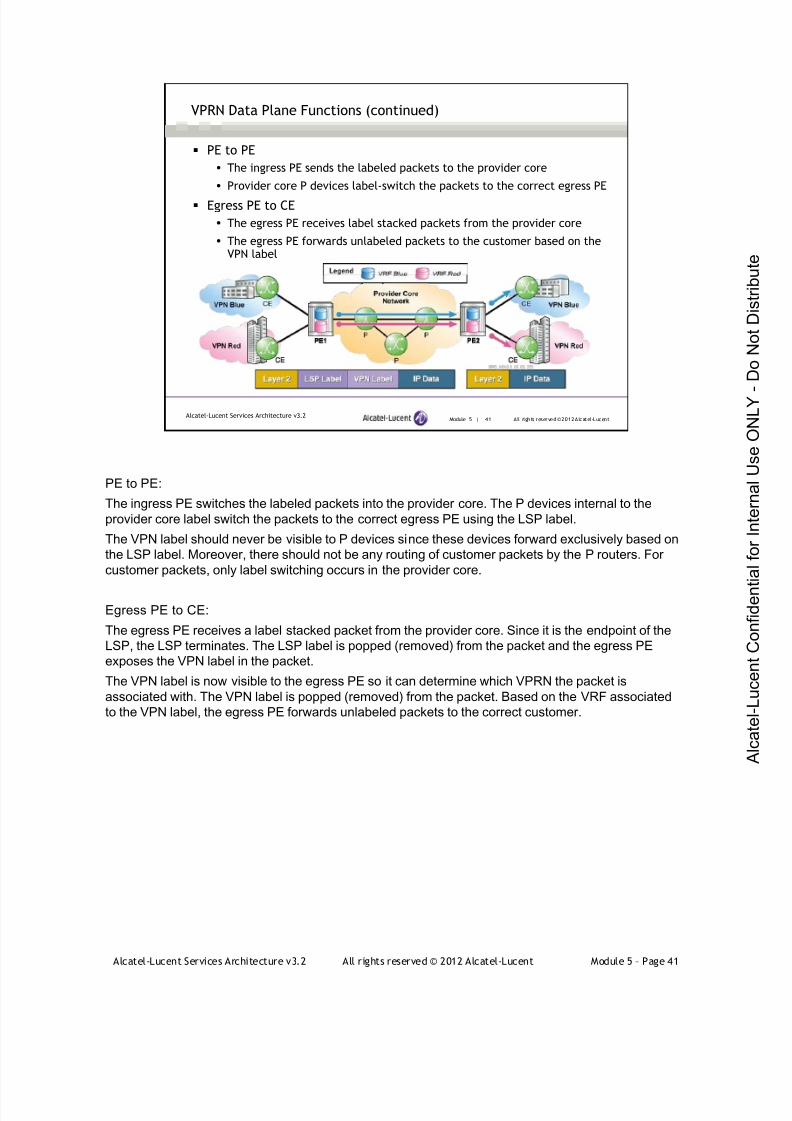
7/21/2019 Services Architecture v3.2 Student Guide Download
http://slidepdf.com/reader/full/services-architecture-v32-student-guide-download 317/429
Alcatel-Lucent Services Architecture v3.2 All rights reserved © 2012 Alcatel-Lucent Module 5 – Page 41
Module 5 | 41 All rights reserved ©2012 Alcatel-LucentAlcatel-Lucent Services Architecture v3.2
VPRN Data Plane Functions (continued)
PE to PE
The ingress PE sends the labeled packets to the provider core
Provider core P devices label-switch the packets to the correct egress PE
Egress PE to CE
The egress PE receives label stacked packets from the provider core
The egress PE forwards unlabeled packets to the customer based on theVPN label
PE to PE:
The ingress PE switches the labeled packets into the provider core. The P devices internal to the
provider core label switch the packets to the correct egress PE using the LSP label.
The VPN label should never be visible to P devices since these devices forward exclusively based on
the LSP label. Moreover, there should not be any routing of customer packets by the P routers. For
customer packets, only label switching occurs in the provider core.
Egress PE to CE:
The egress PE receives a label stacked packet from the provider core. Since it is the endpoint of the
LSP, the LSP terminates. The LSP label is popped (removed) from the packet and the egress PE
exposes the VPN label in the packet.
The VPN label is now visible to the egress PE so it can determine which VPRN the packet is
associated with. The VPN label is popped (removed) from the packet. Based on the VRF associated
to the VPN label, the egress PE forwards unlabeled packets to the correct customer.

7/21/2019 Services Architecture v3.2 Student Guide Download
http://slidepdf.com/reader/full/services-architecture-v32-student-guide-download 318/429
Alcatel-Lucent Services Architecture v3.2 All rights reserved © 2012 Alcatel-Lucent Module 5 – Page 42
Module 5 — Layer 3 VPNs
Section 4 — VPRN Control Plane Details
7/21/2019 Services Architecture v3.2 Student Guide Download
http://slidepdf.com/reader/full/services-architecture-v32-student-guide-download 319/429
Alcatel-Lucent Services Architecture v3.2 All rights reserved © 2012 Alcatel-Lucent Module 5 – Page 43
Module 5 | 43 All rights reserved © 2012 Alcatel-LucentAlcatel-Lucent Services Architecture v3.2
Section Objectives
Explain the role of virtual routing and forwarding instances(VRFs) in establishing a VPRN service
Identify a VPN-IPv4 address family and explain its usage in
VPRN
Define a route distinguisher (RD) and explain its function
Explain how the VPRN routing information is distributed among
PE routers through the use of Multiprotocol BGP extensions
After successfully completing this section, you will be able to:

7/21/2019 Services Architecture v3.2 Student Guide Download
http://slidepdf.com/reader/full/services-architecture-v32-student-guide-download 320/429
Alcatel-Lucent Services Architecture v3.2 All rights reserved © 2012 Alcatel-Lucent Module 5 – Page 44
Module 5 | 44 All rights reserved © 2012 Alcatel-LucentAlcatel-Lucent Services Architecture v3.2
Section Objectives (continued)
Define a route target (RT) and explain how it is used to
identify the set of VPNs in which a particular VRF participates Explain the requirements of distributing VPRN routing
information between PE-CE routers
List transport tunnel creation options and explain how they
are used in VPRN
Demonstrate VPN label signaling via MP-BGP
7/21/2019 Services Architecture v3.2 Student Guide Download
http://slidepdf.com/reader/full/services-architecture-v32-student-guide-download 321/429
Alcatel-Lucent Services Architecture v3.2 All rights reserved © 2012 Alcatel-Lucent Module 5 – Page 45
Module 5 | 45 All r ights reserved ©2012 Alcatel-LucentAlcatel-Lucent Services Architecture v3.2
VPRN Control Plane Tasks
The MPLS/VPRN control plane consists of routing information and
label exchange
Distinct sets of routes must be exchanged
Provider core routing
Customer VPRN routing
Distinct sets of labels must be exchanged
VPN service labels
VPRN control plane tasks include the routing exchange and label exchange. Routes must be
exchanged between all routers in the provider network for core routing purposes and separately
between routers at the customer edge for VPRN connectivity.
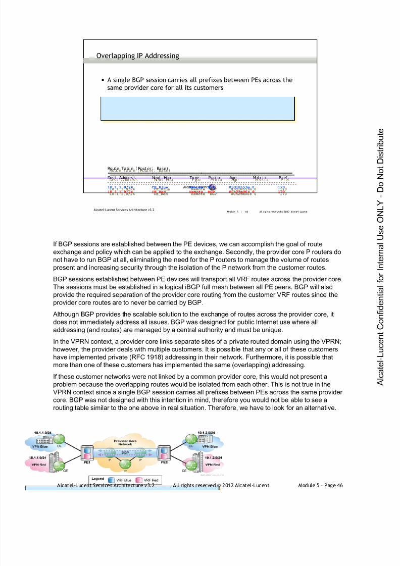
7/21/2019 Services Architecture v3.2 Student Guide Download
http://slidepdf.com/reader/full/services-architecture-v32-student-guide-download 322/429
Alcatel-Lucent Services Architecture v3.2 All rights reserved © 2012 Alcatel-Lucent Module 5 – Page 46
Module 5 | 46 All r ights reserved ©2012 Alcatel-LucentAlcatel-Lucent Services Architecture v3.2
Overlapping IP Addressing
A single BGP session carries all prefixes between PEs across the
same provider core for all its customers
Rout e Tabl e ( Rout er: Base)===============================================================================Dest Address Next Hop Type Proto Age Metr i c Pref - - - - - - - - - - - - - - - - - - - -- - - - - - - - - - - - - - - - - - - - -- - - - - - - - - - - - - - - - - - - - -- - - - - - - - - - - - - - - - -10.1.1.0/24 CE_Blue Remote BGP 03d18h53m 0 170
10.1.1.0/24 CE_Red Remote BGP 00h25m00s 0 170
Rout e Tabl e ( Rout er: Base)===============================================================================Dest Address Next Hop Type Proto Age Metr i c Pref - - - - - - - - - - - - - - - - - - -- - - - - - - - - - - - - - - - - - - - -- - - - - - - - - - - - - - - - - - - - -- - - - - - - - - - - - - - - - - -10.1.1.0/24 CE_Blue Remote BGP 03d18h53m 0 170
10.1.1.0/24 CE_Red Remote BGP 00h25m00s 0 170
If BGP sessions are established between the PE devices, we can accomplish the goal of route
exchange and policy which can be applied to the exchange. Secondly, the provider core P routers do
not have to run BGP at all, eliminating the need for the P routers to manage the volume of routes
present and increasing security through the isolation of the P network from the customer routes.
BGP sessions established between PE devices will transport all VRF routes across the provider core.
The sessions must be established in a logical iBGP full mesh between all PE peers. BGP will also
provide the required separation of the provider core routing from the customer VRF routes since theprovider core routes are to never be carried by BGP.
Although BGP provides the scalable solution to the exchange of routes across the provider core, it
does not immediately address all issues. BGP was designed for public Internet use where all
addressing (and routes) are managed by a central authority and must be unique.
In the VPRN context, a provider core links separate sites of a private routed domain using the VPRN;
however, the provider deals with multiple customers. It is possible that any or all of these customers
have implemented private (RFC 1918) addressing in their network. Furthermore, it is possible that
more than one of these customers has implemented the same (overlapping) addressing.
If these customer networks were not linked by a common provider core, this would not present a
problem because the overlapping routes would be isolated from each other. This is not true in the
VPRN context since a single BGP session carries all prefixes between PEs across the same provider
core. BGP was not designed with this intention in mind, therefore you would not be able to see a
routing table similar to the one above in real situation. Therefore, we have to look for an alternative.

7/21/2019 Services Architecture v3.2 Student Guide Download
http://slidepdf.com/reader/full/services-architecture-v32-student-guide-download 323/429
Alcatel-Lucent Services Architecture v3.2 All rights reserved © 2012 Alcatel-Lucent Module 5 – Page 47
Module 5 | 47 All r ights reserved ©2012 Alcatel-LucentAlcatel-Lucent Services Architecture v3.2
Overlapping IP Addressing Problem
Multiple customers can have the same IP address architecture
Routes from different customers with the same IPv4 address prefix
are treated as equivalent by BGP
Only one route will be selected as 'best' according to the route
selection criteria
Fl ag Net wor k Next hop Local P ref MEDVPN Label As- Path
- - - - - - - - - - - - - - - - - - - -- - - - - - - - - - - - - - - - - - - - -- - - - - - - - - - - - - - - - - - - - -- - - - - - - - - - - - - - - - -u*> 10.1.1.0/24 CE_Blue none none
64496
u* 10.1.1.0/24 CE_Red none none
64497
Fl ag Net wor k Next hop Local P ref MEDVPN Label As- Path
- - - - - - - - - - - - - - - - - - - -- - - - - - - - - - - - - - - - - - - - -- - - - - - - - - - - - - - - - - - - - -- - - - - - - - - - - - - - - - -u*> 10.1.1.0/24 CE_Blue none none
64496
u* 10.1.1.0/24 CE_Red none none
64497
An important consideration to note with overlapping addressing is that if BGPv4 sees two (or more)
separate entries for the same IPv4 address prefix, it will treat these prefixes as if they are going to the
same destination and will install only one route in the routing table (by default) based on the route
selection criteria.
In the case of VPRN, this poses a problem. The routes are for the same destination prefix but have
originated in different customer VPRNs. Therefore, they are completely separate and distinct
destination networks.
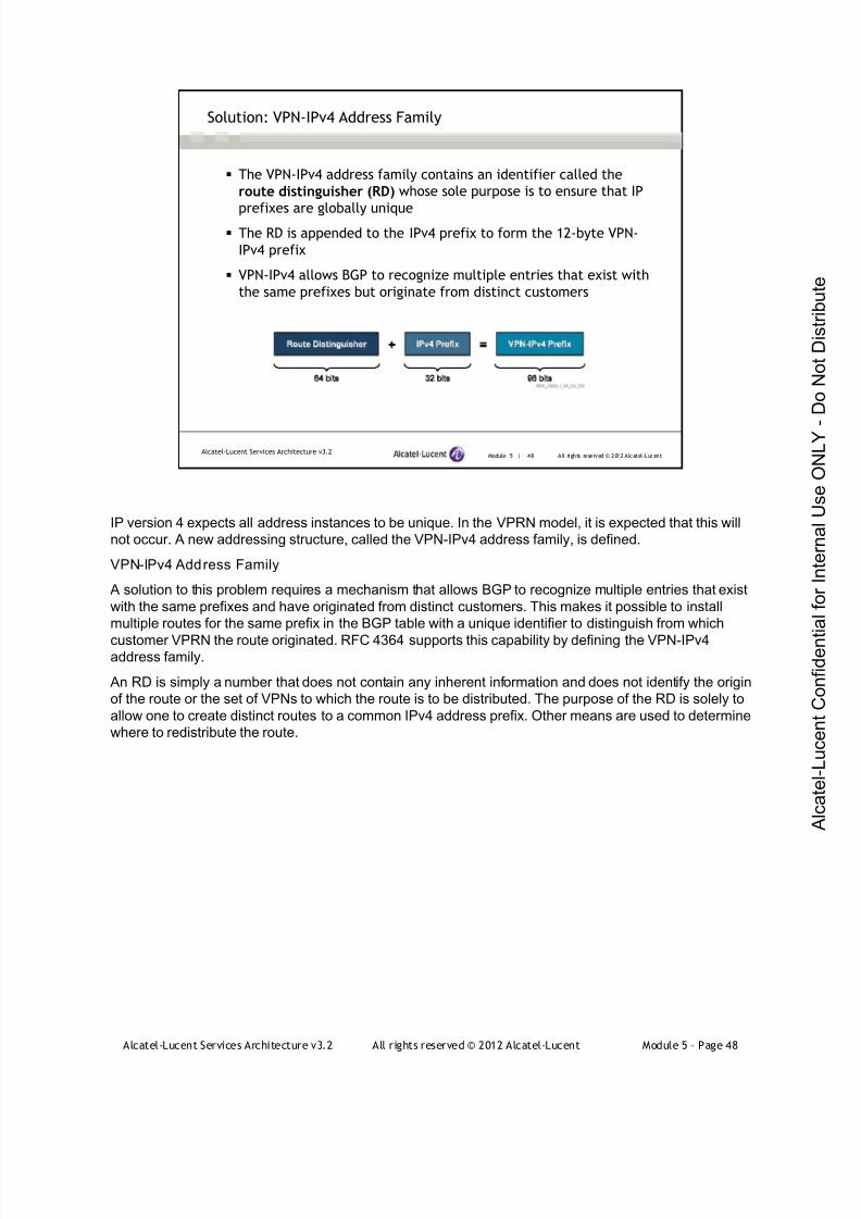
7/21/2019 Services Architecture v3.2 Student Guide Download
http://slidepdf.com/reader/full/services-architecture-v32-student-guide-download 324/429
Alcatel-Lucent Services Architecture v3.2 All rights reserved © 2012 Alcatel-Lucent Module 5 – Page 48
IP version 4 expects all address instances to be unique. In the VPRN model, it is expected that this will
not occur. A new addressing structure, called the VPN-IPv4 address family, is defined.
VPN-IPv4 Address Family
A solution to this problem requires a mechanism that allows BGP to recognize multiple entries that exist
with the same prefixes and have originated from distinct customers. This makes it possible to install
multiple routes for the same prefix in the BGP table with a unique identifier to distinguish from which
customer VPRN the route originated. RFC 4364 supports this capability by defining the VPN-IPv4address family.
An RD is simply a number that does not contain any inherent information and does not identify the origin
of the route or the set of VPNs to which the route is to be distributed. The purpose of the RD is solely to
allow one to create distinct routes to a common IPv4 address prefix. Other means are used to determine
where to redistribute the route.
Module 5 | 48 All rights reserved © 2012 Alcatel-LucentAlcatel-Lucent Services Architecture v3.2
Solution: VPN-IPv4 Address Family
The VPN-IPv4 address family contains an identifier called the
route distinguisher (RD) whose sole purpose is to ensure that IP
prefixes are globally unique The RD is appended to the IPv4 prefix to form the 12-byte VPN-
IPv4 prefix
VPN-IPv4 allows BGP to recognize multiple entries that exist with
the same prefixes but originate from distinct customers

7/21/2019 Services Architecture v3.2 Student Guide Download
http://slidepdf.com/reader/full/services-architecture-v32-student-guide-download 325/429
Alcatel-Lucent Services Architecture v3.2 All rights reserved © 2012 Alcatel-Lucent Module 5 – Page 49
Module 5 | 49 All r ights reserved ©2012 Alcatel-LucentAlcatel-Lucent Services Architecture v3.2
The route distinguisher is an 8-byte parameter containing three fields:
Type (2 bytes)
Administrator (Length) Assigned Number (Value)
ALU supports the three types of RDs defined in RFC 4364
Route Distinguisher Format
Type Administrator Assigned Number VPN-IPv4 example
2 Bytes (Type 0) 2 Bytes (ASN) 4 Bytes 0:64496:100:10.1.1.0/24
2 Bytes (Type 1) 4 Bytes (IP Address) 2 Bytes 1:10.10.10.10:100:10.1.1.0/24
2 Bytes (Type 2) 4 Bytes (ASN) 2 Bytes 2:64496:100:10.1.1.0/24
The Alcatel-Lucent 7750 SR supports type 0, 1, and 2 route distinguisher formats.
Type 0
Administrator subfield (2 bytes)
Assigned number subfield (4 bytes)
The administrator field must contain an AS number (using private AS numbers is discouraged). The assigned
number field contains a number assigned by the service provider.
Example: For the IPv4 address 10.1.1.0/24, the VPN-IPv4 address is 0:64496:100:10.1.1.0/24 where 64496 isthe AS number and 100 is the assigned number.
Type 1
Administrator subfield (4 bytes)
Assigned number subfield (2 bytes)
The administrator field must contain an IP address (using a private IP address space is discouraged). The
assigned number field contains a number assigned by the service provider.
Example: For the IPv4 address 10.1.1.0/24, the VPN-IPv4 address is 1:10.10.10.10:100:10.1.1.0/24 where
10.10.10.10 is the IP address and 100 is the assigned number.
Type 2
Administrator subfield (4 bytes)
Assigned number subfield (2 bytes)
The administrator field must contain a 4-byte AS number (using a private AS number is discouraged). Theassigned number field contains a number assigned by the service provider.
Example: For the IPv4 address 10.1.1.0/24, the VPN-IPv4 address is 2:64496:100:10.1.1.0/24 where 64496 is
the 4 byte AS number and 100 is the assigned number.
The VPN-IPv4 address appears only in the PE control plane - it is added when the prefix is exported from the
VRF to the VPRN. The CE router never sees the VPN-IPv4 address and it never appears anywhere in any IP
packet on the network. Usually, it makes sense to assign the same route distinguisher to the VRFs of sites
belonging to the same VPRN so that all the routes of the network will have the same route distinguisher. For
more information about BGP support for four-octet AS number space, refer to RFC 4893.

7/21/2019 Services Architecture v3.2 Student Guide Download
http://slidepdf.com/reader/full/services-architecture-v32-student-guide-download 326/429
Alcatel-Lucent Services Architecture v3.2 All rights reserved © 2012 Alcatel-Lucent Module 5 – Page 50
Module 5 | 50 All r ights reserved ©2012 Alcatel-LucentAlcatel-Lucent Services Architecture v3.2
Multiprotocol BGP (MP-BGP) extensions allow VPN-IPv4 prefixes to
distribute VPRN routing information across the service provider’s network
The VPN-IPv4 address family is only used in the provider core control plane
when exchanging MP-BGP routing updates.
Multiprotocol BGP (MP-BGP)
Multiprotocol Border Gateway Protocol (MP-BGP)
MP-BGP extensions are used to encode customer IPv4 address prefixes into unique VPN-IPv4
Network Layer Reachability Information (NLRI) values. NLRI refers to a destination address in MP-
BGP. In the context of IPv4 MP-BGP, NLRI refers to VPN-IPv4 Prefix that is carried in the BGP routing
updates.
The multiprotocol nature of MP-BGP allows the overlapping routing information to be transported
across the provider core as VPN-IPv4 addressing. VPRN routes are not distributed within the providercore network as IPv4 routes, but as 12-byte VPN-IPv4 routes.
VPN-IPv4 addresses are only present within the service provider network and should never be made
visible to the customer. They are created at the ingress PE by appending a route distinguisher to the
customer route and are transported across the provider domain. At the egress PE, the route
distinguisher is removed from the route and a traditional IPv4 route is restored.
It is important to note that the VPN-IPv4 address family is used only in the provider core control plane
when exchanging MP-BGP routing updates between PEs. All data traffic is carried in standard IP
version 4 packets.

7/21/2019 Services Architecture v3.2 Student Guide Download
http://slidepdf.com/reader/full/services-architecture-v32-student-guide-download 327/429
Alcatel-Lucent Services Architecture v3.2 All rights reserved © 2012 Alcatel-Lucent Module 5 – Page 51
Module 5 | 51 All r ights reserved ©2012 Alcatel-LucentAlcatel-Lucent Services Architecture v3.2
Multiprotocol BGP (MP-BGP) (continued)
The sending PE will add the RD to the IPv4 prefixes before sending the
VPN-IPv4 prefixes in MP-BGP updates
Problem: How will the receiving PE know which routes belong to which
VRFs?
MP-BGP Updatereceived at PE-2
When using the MP-BGP: before sending an update to the remote PE, the sending PE will prepend a
unique (per-customer) 64-bit route distinguisher to each customer’s 32-bit IPv4 prefix thus exchanging
unique VPN-IPv4 routing updates with the remote PE. The PE routers (BGP peers) will send each
other these prepended VPN-IPv4 routes. Now how is the router going to know what routes belong to
which VRF?
A new identifier, separate from the route distinguisher, is required to associate a route to a VRF and
defines the VPRN membership of the route. This identifier is called route target.

7/21/2019 Services Architecture v3.2 Student Guide Download
http://slidepdf.com/reader/full/services-architecture-v32-student-guide-download 328/429
Alcatel-Lucent Services Architecture v3.2 All rights reserved © 2012 Alcatel-Lucent Module 5 – Page 52
BGP-extended community is a mechanism for including additional information to be carried in BGP
updates. The route target (RT) is the closest approximation to a VPRN membership identifier in the
VPRN architecture, and identifies the VRF table that a prefix is associated with to the receiving PE.
When a VPN-IPv4 route is created (from an IPv4 route that the PE has acquired from a CE) by a PE
router, it is associated with one or more route target attributes. These are carried in BGP as attributes of
the route. Any route associated with route target T must be distributed to every PE router that has a VRF
associated with route target T. When such a route is received by a PE router, it is eligible to be installed
in the PE’s VRFs that are associated with route target T.
A route target attribute can be thought of as identifying a set of sites or a set of VRFs. It is used to filter
the appropriate routes into the correct VRFs.
Module 5 | 52 All rights reserved © 2012 Alcatel-LucentAlcatel-Lucent Services Architecture v3.2
Route Target (RT)
Route Target (RT) is a BGP extended community used to advertise
the VPRN membership identifier to the receiving PE
RT is the mechanism from which VPRN controls the distribution of
VPN routing information

7/21/2019 Services Architecture v3.2 Student Guide Download
http://slidepdf.com/reader/full/services-architecture-v32-student-guide-download 329/429
Alcatel-Lucent Services Architecture v3.2 All rights reserved © 2012 Alcatel-Lucent Module 5 – Page 53
Module 5 | 53 All r ights reserved ©2012 Alcatel-LucentAlcatel-Lucent Services Architecture v3.2
Multiprotocol BGP (MP-BGP) (continued)
MP-BGP updates include VPN-IPv4 unique addressing for customer routes
and the RT to identify VPRN membership at the receiving PE
The route target identifies to the receiving PE the VRF that a VPN-IPv4
prefix is associated with
MP-BGP Updatereceived at PE-2
The routes associated with a VRF are ‘exported’ out of the VRF table of the originating PE with
defined route target values associated to the prefix. VPN-IPv4 prefixes are exported by a PE with the
route target attached.
The receiving PE will install routes into the associated VRFs if its configured ‘import’ route target is the
same value as the route target 'exported' by the originating PEs. For example, if routes are exported
on the sending PE with a route target value of '64496:10', these routes will only be imported into a
VRF on the receiving PE if that VRF imports route target values of '64496:10'.Each VPRN route is tagged with one or more route target values when it is exported from a VRF by
the sending PE and transported across the provider core by MP-BGP. Therefore, the import route
target value of the receiving PE should match the export route target value of the originating PE.
You can also associate a set of route targets with a VRF, and any route tagged with at least one of
those route targets will be imported into the VRF. This technique allows the creation of complex VPRN
topologies. In these cases, a single VPRN might need more than one route target for successful
implementation, and VRF policies must be used instead of the simple vrf-target command. This is
discussed in details in the VPRN course.

7/21/2019 Services Architecture v3.2 Student Guide Download
http://slidepdf.com/reader/full/services-architecture-v32-student-guide-download 330/429
Alcatel-Lucent Services Architecture v3.2 All rights reserved © 2012 Alcatel-Lucent Module 5 – Page 54
Module 5 | 54 All r ights reserved ©2012 Alcatel-LucentAlcatel-Lucent Services Architecture v3.2
PE to CE Route Exchange
IPv4 routing information is exchanged between the PE and CE after
being received via MP-BGP updates over the provider core
Routing protocol, or static routes, may be used to propagate routesto the CE
A routing protocol must be run between the PE and CE for the purposes of exchanging the customer
routing information from the receiving PE to the customer sites. The receiving PE will propagate routes
from the VRF to the CE as IPv4 routes.
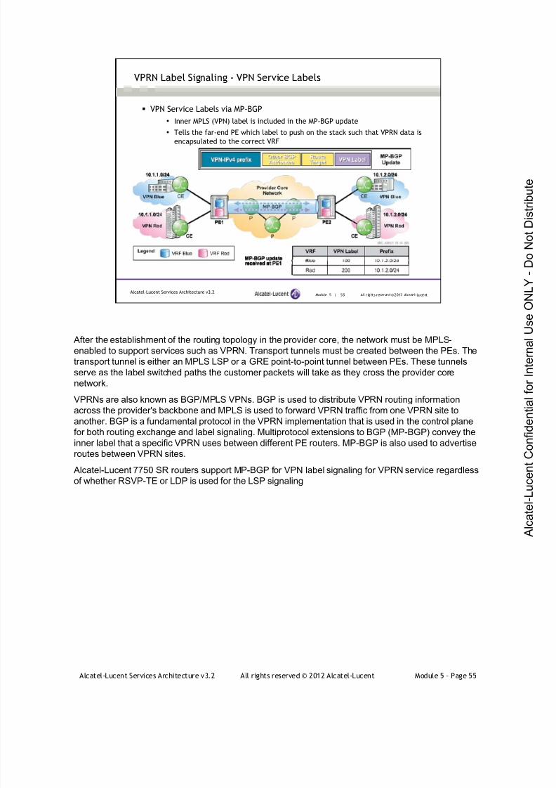
7/21/2019 Services Architecture v3.2 Student Guide Download
http://slidepdf.com/reader/full/services-architecture-v32-student-guide-download 331/429
Alcatel-Lucent Services Architecture v3.2 All rights reserved © 2012 Alcatel-Lucent Module 5 – Page 55
Module 5 | 55 All r ights reserved ©2012 Alcatel-LucentAlcatel-Lucent Services Architecture v3.2
VPN Service Labels via MP-BGP
Inner MPLS (VPN) label is included in the MP-BGP update
Tells the far-end PE which label to push on the stack such that VPRN data is
encapsulated to the correct VRF
VPRN Label Signaling - VPN Service Labels
After the establishment of the routing topology in the provider core, the network must be MPLS-
enabled to support services such as VPRN. Transport tunnels must be created between the PEs. The
transport tunnel is either an MPLS LSP or a GRE point-to-point tunnel between PEs. These tunnels
serve as the label switched paths the customer packets will take as they cross the provider core
network.
VPRNs are also known as BGP/MPLS VPNs. BGP is used to distribute VPRN routing information
across the provider's backbone and MPLS is used to forward VPRN traffic from one VPRN site toanother. BGP is a fundamental protocol in the VPRN implementation that is used in the control plane
for both routing exchange and label signaling. Multiprotocol extensions to BGP (MP-BGP) convey the
inner label that a specific VPRN uses between different PE routers. MP-BGP is also used to advertise
routes between VPRN sites.
Alcatel-Lucent 7750 SR routers support MP-BGP for VPN label signaling for VPRN service regardless
of whether RSVP-TE or LDP is used for the LSP signaling

7/21/2019 Services Architecture v3.2 Student Guide Download
http://slidepdf.com/reader/full/services-architecture-v32-student-guide-download 332/429
Alcatel-Lucent Services Architecture v3.2 All rights reserved © 2012 Alcatel-Lucent Module 5 – Page 56
The 7750 SR supports multiple mechanisms to provide transport tunnels for the forwarding of traffic between PE
routers:
RSVP-TE protocol to create tunnel LSP's between PE routers
LDP protocol to create tunnel LSP's between PE routers
GRE tunnels between PE routers.
The transport tunnel in a VPRN is created either by configuring the auto-bind option under the VPRN service
instance or by configuring an SDP and binding the VPRN service instance to the SDP instance.
When the 'auto-bind' command is used, next-hop resolution refers to the base (core) routing instance for IP
reachability. For VPRN service, auto-bind specifies the lookup to be used by the routing instance if an SDP to the
destination does not exist. In this way auto-bind acts as a replacement by creating SDPs for the transport tunnels
manually.
• Auto-bind ldp binds the VPRN service to the LDP FECs in the core without the need to configure SDPs explicitly
• Auto-bind rsvp-te
Allows the use of traffic-engineered paths between PE routers for VPRN services without explicitly
defining them through the SDP configuration mechanism.
If configured, this feature will use the RSVP-TE-based LSP with the lowest metric to resolve the MP-
BGP route within a VPRN context.
Auto-bind mpls allows auto-bind to select available RSVP-TE or LDP LSPs to resolve IP-VPN routes from
remote PEs.
For VPRN services, SDP tunnels can be created using MPLS/rsvp-te. If SDP-based tunnels are used, they must
be created prior to their binding to the VPRN service. The configuration of an SDP includes specifying the far-end
PE address and the type of encapsulation used, such as MPLS.
Module 5 | 56 All rights reserved © 2012 Alcatel-LucentAlcatel-Lucent Services Architecture v3.2
Creating MPLS Transport in a VPRN
Using the auto-bind option under the VPRN service instance
auto-bind allows a VPRN service to automatically resolve the BGP next-
hop from VPRN routes to a GRE or MPLS LSP auto-bind specifies the lookup to be used by the routing instance if an
SDP to the destination does not exist
Alcatel-Lucent 7750 SR supports auto-bind {ldp|gre|rsvp-te|mpls}options
Configure SDP and bind the VPRN service instance to the SDP
instance
7/21/2019 Services Architecture v3.2 Student Guide Download
http://slidepdf.com/reader/full/services-architecture-v32-student-guide-download 333/429
Alcatel-Lucent Services Architecture v3.2 All rights reserved © 2012 Alcatel-Lucent Module 5 – Page 57
Module 5 — Layer 3 VPNs
Section 5 — VPRN Case Study

7/21/2019 Services Architecture v3.2 Student Guide Download
http://slidepdf.com/reader/full/services-architecture-v32-student-guide-download 334/429
Alcatel-Lucent Services Architecture v3.2 All rights reserved © 2012 Alcatel-Lucent Module 5 – Page 58
Module 5 | 58 All rights reserved © 2012 Alcatel-LucentAlcatel-Lucent Services Architecture v3.2
Section Objectives
Identify the requirements for a successful operation of a VPRNservice
Configure a MP-BGP for the provider network and verify its
operation
Configure VPRN service instances and verify their operations
Configure a PE-CE routing protocol (BGP) and verify its
operation
After successfully completing this section, you will be able to:

7/21/2019 Services Architecture v3.2 Student Guide Download
http://slidepdf.com/reader/full/services-architecture-v32-student-guide-download 335/429
Alcatel-Lucent Services Architecture v3.2 All rights reserved © 2012 Alcatel-Lucent Module 5 – Page 59
Module 5 | 59 All rights reserved © 2012 Alcatel-LucentAlcatel-Lucent Services Architecture v3.2
Section Objectives (Continued)
Demonstrate an end-to-end route exchange for a given VPRN
network.
Demonstrate an end-to-end data flow for a given VPRN
network.
Verify that the VPRN service is operational using OAM tools
(oam vprn ping, oam vprn trace)
Complete Lab 9 – Configure and verify basic IPv4 VPRN using
LDP.

7/21/2019 Services Architecture v3.2 Student Guide Download
http://slidepdf.com/reader/full/services-architecture-v32-student-guide-download 336/429
Alcatel-Lucent Services Architecture v3.2 All rights reserved © 2012 Alcatel-Lucent Module 5 – Page 60
Module 5 | 60 All r ights reserved ©2012 Alcatel-LucentAlcatel-Lucent Services Architecture v3.2
Network Diagram
The network diagram will be used to demonstrate the configuration and operation of VPRN.
The loopback interfaces simulate locally-connected networks.
Customer sites, belonging to different VPRNs, will be able to use the same private IP address space.
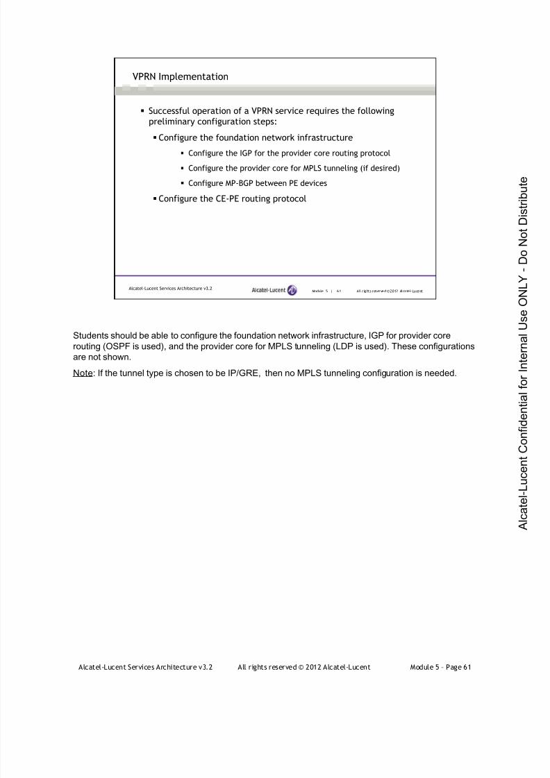
7/21/2019 Services Architecture v3.2 Student Guide Download
http://slidepdf.com/reader/full/services-architecture-v32-student-guide-download 337/429
Alcatel-Lucent Services Architecture v3.2 All rights reserved © 2012 Alcatel-Lucent Module 5 – Page 61
Module 5 | 61 All r ights reserved ©2012 Alcatel-LucentAlcatel-Lucent Services Architecture v3.2
VPRN Implementation
Successful operation of a VPRN service requires the following
preliminary configuration steps:
Configure the foundation network infrastructure
Configure the IGP for the provider core routing protocol
Configure the provider core for MPLS tunneling (if desired)
Configure MP-BGP between PE devices
Configure the CE-PE routing protocol
Students should be able to configure the foundation network infrastructure, IGP for provider core
routing (OSPF is used), and the provider core for MPLS tunneling (LDP is used). These configurations
are not shown.
Note: If the tunnel type is chosen to be IP/GRE, then no MPLS tunneling configuration is needed.
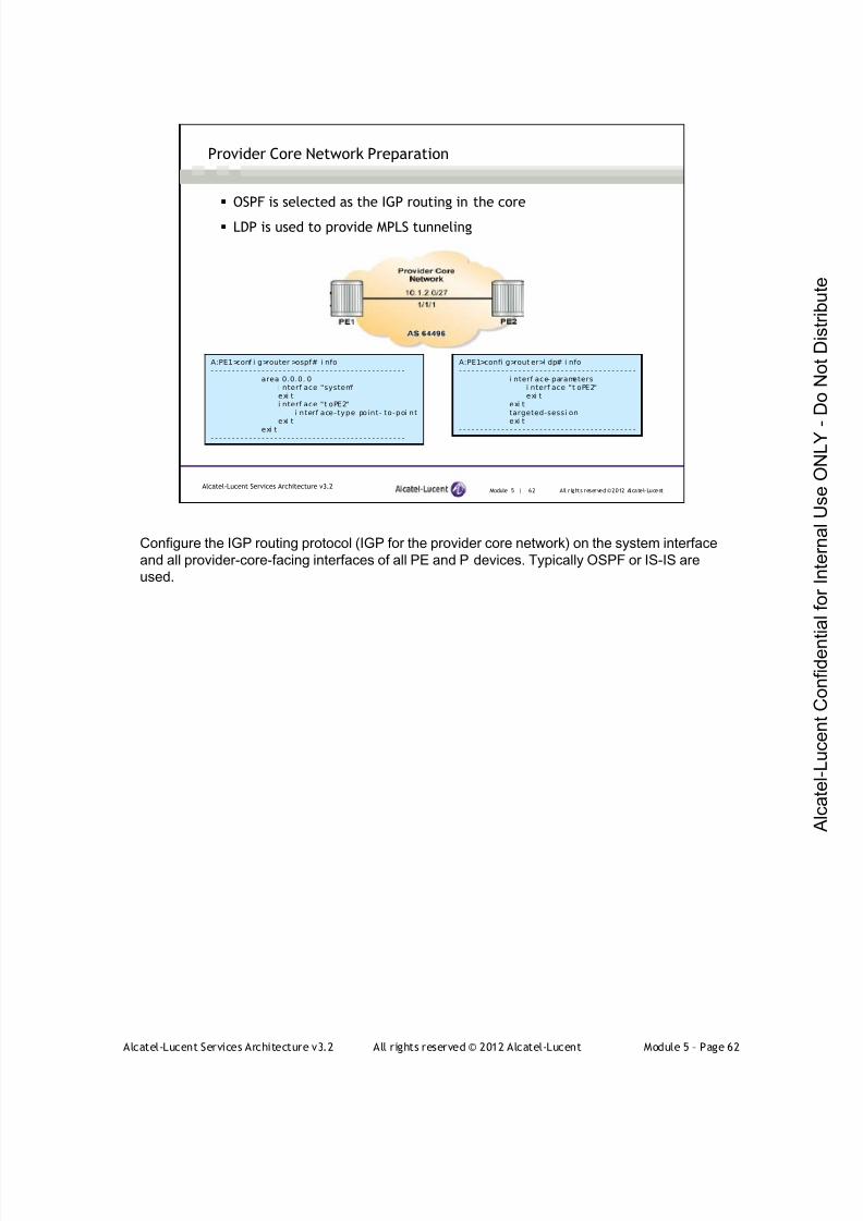
7/21/2019 Services Architecture v3.2 Student Guide Download
http://slidepdf.com/reader/full/services-architecture-v32-student-guide-download 338/429
Alcatel-Lucent Services Architecture v3.2 All rights reserved © 2012 Alcatel-Lucent Module 5 – Page 62
Module 5 | 62 All r ights reserved ©2012 Alcatel-LucentAlcatel-Lucent Services Architecture v3.2
Provider Core Network Preparation
OSPF is selected as the IGP routing in the core
LDP is used to provide MPLS tunneling
A:PE1>conf i g>router >ospf# i nfo- - - - - - - - - - - - - - - - - - - - - - - - - - - - - - - - - - - - - - - - - - - - - -
area 0.0.0. 0i nterf ace "system"exi ti nterf ace "t oPE2"
i nterf ace-type point- to-poi ntexi t
exi t- - - - - - - - - - - - - - - - - - - - - - - - - - - - - - - - - - - - - - - - - - - - - -
A:PE1>confi g>rout er>l dp# i nfo- - - - - - - - - - - - - - - - - - - - - - - - - - - - - - - - - - - - - - - - - -
i nterf ace- parametersi nterf ace "t oPE2"exi t
exi ttargeted-sessi onexi t
- - - - - - - - - - - - - - - - - - - - - - - - - - - - - - - - - - - - - - - - - -
Configure the IGP routing protocol (IGP for the provider core network) on the system interface
and all provider-core-facing interfaces of all PE and P devices. Typically OSPF or IS-IS are
used.
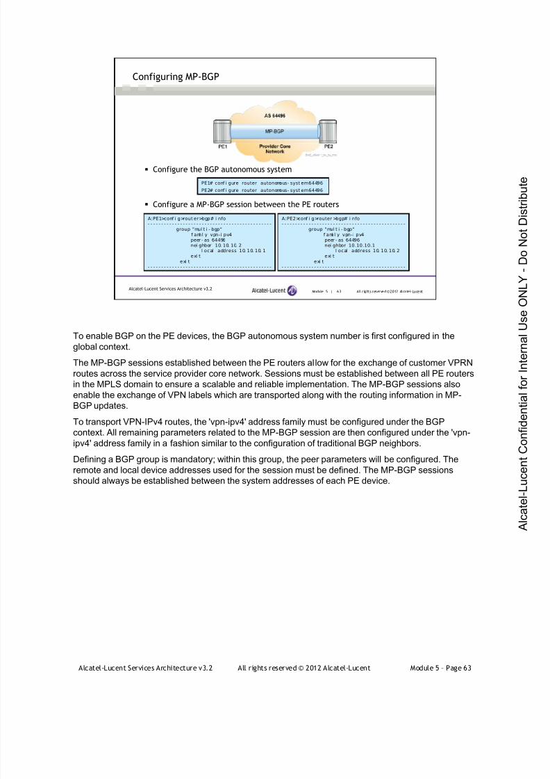
7/21/2019 Services Architecture v3.2 Student Guide Download
http://slidepdf.com/reader/full/services-architecture-v32-student-guide-download 339/429
Alcatel-Lucent Services Architecture v3.2 All rights reserved © 2012 Alcatel-Lucent Module 5 – Page 63
Module 5 | 63 All r ights reserved ©2012 Alcatel-LucentAlcatel-Lucent Services Architecture v3.2
Configure the BGP autonomous system
Configure a MP-BGP session between the PE routers
Configuring MP-BGP
PE1# conf i gure router autonomous- syst em64496
PE2# conf i gure router autonomous- syst em64496
A:PE1>conf i g>rout er>bgp# i nfo- - - - - - - - - - - - - - - - - - - - - - - - - - - - - - - - - - - - - - - - - - - - - -
group "mul t i - bgp“f ami l y vpn-i pv4peer - as 64496nei ghbor 10. 10. 10. 2
l ocal - address 10. 10. 10. 1exi t
exi t- - - - - - - - - - - - - - - - - - - - - - - - - - - - - - - - - - - - - - - - - - - - - -
A:PE2>conf i g>router >bgp# i nfo- - - - - - - - - - - - - - - - - - - - - - - - - - - - - - - - - - - - - - - - - - - - - -
group "mul t i - bgp“f ami l y vpn-i pv4peer - as 64496nei ghbor 10.10.10.1
l ocal - address 10. 10. 10. 2exi t
exi t- - - - - - - - - - - - - - - - - - - - - - - - - - - - - - - - - - - - - - - - - - - - - -
To enable BGP on the PE devices, the BGP autonomous system number is first configured in the
global context.
The MP-BGP sessions established between the PE routers allow for the exchange of customer VPRN
routes across the service provider core network. Sessions must be established between all PE routers
in the MPLS domain to ensure a scalable and reliable implementation. The MP-BGP sessions also
enable the exchange of VPN labels which are transported along with the routing information in MP-
BGP updates.To transport VPN-IPv4 routes, the 'vpn-ipv4' address family must be configured under the BGP
context. All remaining parameters related to the MP-BGP session are then configured under the 'vpn-
ipv4' address family in a fashion similar to the configuration of traditional BGP neighbors.
Defining a BGP group is mandatory; within this group, the peer parameters will be configured. The
remote and local device addresses used for the session must be defined. The MP-BGP sessions
should always be established between the system addresses of each PE device.

7/21/2019 Services Architecture v3.2 Student Guide Download
http://slidepdf.com/reader/full/services-architecture-v32-student-guide-download 340/429
Alcatel-Lucent Services Architecture v3.2 All rights reserved © 2012 Alcatel-Lucent Module 5 – Page 64
Module 5 | 64 All r ights reserved ©2012 Alcatel-LucentAlcatel-Lucent Services Architecture v3.2
Verifying MP-BGP sessions
A: PE1#show router bgp nei ghbor- - - - - - - - - - - - - - - - - - - - - - - - - - - - - - - - - - - - - - - - - - - - - - - - - - - - - - - - - - - - - - - - - - - - - - - - - - - - - - -BGP Nei ghbor- - - - - - - - - - - - - - - - - - - - - - - - - - - - - - - - - - - - - - - - - - - - - - - - - - - - - - - - - - - - - - - - - - - - - - - - - - - - - - -Peer : 10. 10. 10. 2Group : mul t i - bgp- - - - - - - - - - - - - - - - - - - - - - - - - - - - - - - - - - - - - - - - - - - - - - - - - - - - - - - - - - - - - - - - - - - - - - - - - - - - - - -Peer AS : 64496 Peer Port : 179Peer Address : 10. 10. 10. 2Local AS : 64496 Local Port : 50603Local Address : 10. 10. 10. 1Peer Type : I nternalStat e : Establ i shed Last Stat e : OpenSentLast Event : recvKeepAl i veLast Error : CeaseLocal Fami l y : VPN- I Pv4Remote Fami l y : VPN- I Pv4
- output omi t t ed -
Local Capabi l i t y : Rt Refr esh MPBGP 4byte ASNRemote Capabi l i t y : Rt Ref r esh MPBGP 4byte ASNI mport Pol i cy : None Specif i ed / I nheri tedExport Pol i cy : None Specif i ed / I nheri ted- - - - - - - - - - - - - - - - - - - - - - - - - - - - - - - - - - - - - - - - - - - - - - - - - - - - - - - - - - - - - - - - - - - - - - - - - - - - - - -Nei ghbors : 1
Check that the MP-BGP sessions are established between all PE
routers.
The show router bgp neighbor command is used to verify the details of the BGP sessions of the PE,
including the operational status of the MP-BGP sessions.
The following is shown in the slide:
The verification of the internal PE neighbor
The VPN-IPv4 address family is supported between the neighbors for the purpose of VPRN
route exchange

7/21/2019 Services Architecture v3.2 Student Guide Download
http://slidepdf.com/reader/full/services-architecture-v32-student-guide-download 341/429
Alcatel-Lucent Services Architecture v3.2 All rights reserved © 2012 Alcatel-Lucent Module 5 – Page 65
Module 5 | 65 All r ights reserved ©2012 Alcatel-LucentAlcatel-Lucent Services Architecture v3.2
Configuring a VPRN on the PE
The steps required to configure a VPRN include:
Creating customer accounts
Configuring VPRN service instances
Create VPRN service instances
Define route distinguishers
Define route targets
Configuring VPRN interfaces
Configuring the tunnel type
Activating the VPRN service
The service configuration commands to provision a VPRN service are located under the
‘config>service>vprn’ context
The show commands are in the ‘show>service’ context.
A summary of the steps required to provision a VPRN customer are shown and detailed in the
following pages. Only the configurations on PE1 will be shown.
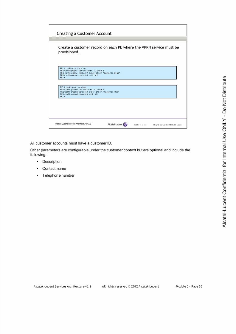
7/21/2019 Services Architecture v3.2 Student Guide Download
http://slidepdf.com/reader/full/services-architecture-v32-student-guide-download 342/429
Alcatel-Lucent Services Architecture v3.2 All rights reserved © 2012 Alcatel-Lucent Module 5 – Page 66
All customer accounts must have a customer ID.
Other parameters are configurable under the customer context but are optional and include the
following:
• Description
• Contact name
• Telephone number
Module 5 | 66 All rights reserved © 2012 Alcatel-LucentAlcatel-Lucent Services Architecture v3.2
Creating a Customer Account
Create a customer record on each PE where the VPRN service must be
provisioned.
PE1# conf i gure servi cePE1>confi g>servi ce# customer 10 cr eat ePE1>confi g>servi ce>cust# descr i pti on "Customer Bl ue"PE1>confi g>servi ce>cust# exit al lPE1#
PE1# conf i gure servi cePE1>conf i g>servi ce# customer 20 cr eat ePE1>conf i g>servi ce>cust# descr i pti on " Customer Red"PE1>conf i g>servi ce>cust# exit al lPE1#
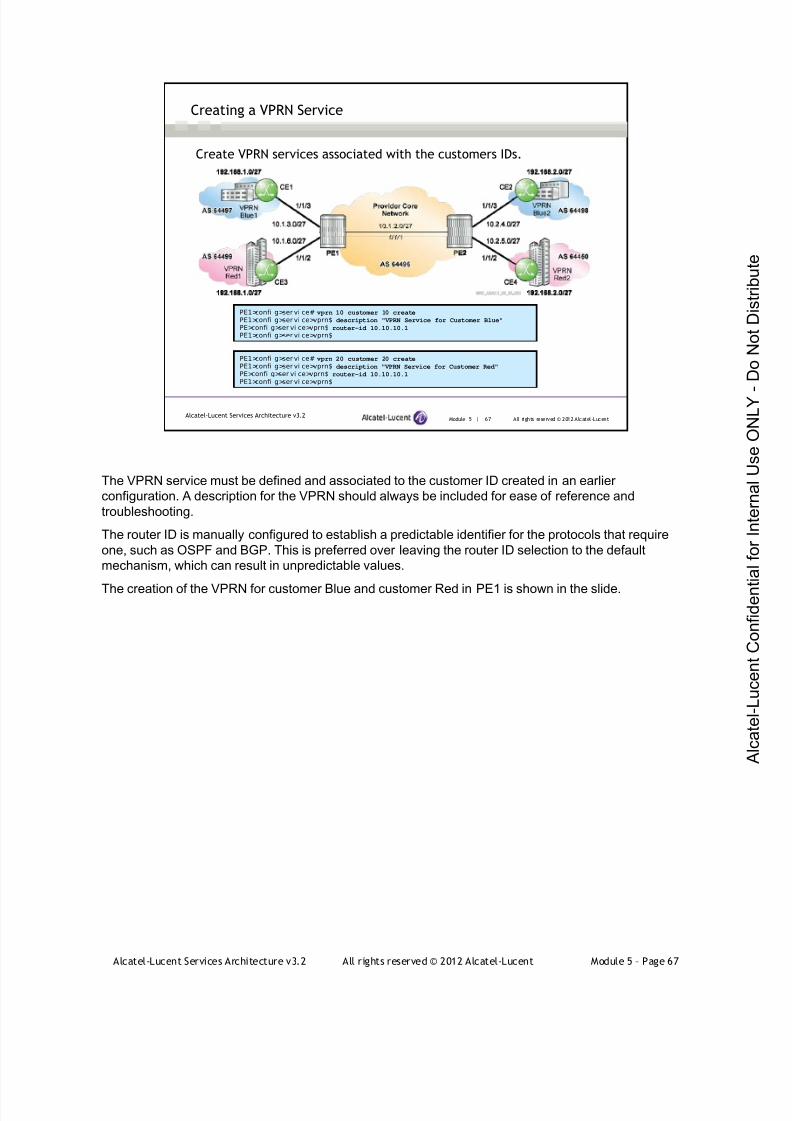
7/21/2019 Services Architecture v3.2 Student Guide Download
http://slidepdf.com/reader/full/services-architecture-v32-student-guide-download 343/429
Alcatel-Lucent Services Architecture v3.2 All rights reserved © 2012 Alcatel-Lucent Module 5 – Page 67
The VPRN service must be defined and associated to the customer ID created in an earlier
configuration. A description for the VPRN should always be included for ease of reference and
troubleshooting.
The router ID is manually configured to establish a predictable identifier for the protocols that require
one, such as OSPF and BGP. This is preferred over leaving the router ID selection to the default
mechanism, which can result in unpredictable values.
The creation of the VPRN for customer Blue and customer Red in PE1 is shown in the slide.
Module 5 | 67 All rights reserved © 2012 Alcatel-LucentAlcatel-Lucent Services Architecture v3.2
Creating a VPRN Service
Create VPRN services associated with the customers IDs.
PE1>confi g>ser vi ce# vprn 10 customer 10 create
PE1>confi g>ser vi ce>vprn$ description "VPRN Service for Customer Blue"
PE>confi g>ser vi ce>vprn$ router-id 10.10.10.1
PE1>confi g>ser vi ce>vprn$
PE1>confi g>ser vi ce# vprn 20 customer 20 create
PE1>confi g>ser vi ce>vprn$ description "VPRN Service for Customer Red"
PE>confi g>ser vi ce>vprn$ router-id 10.10.10.1
PE1>confi g>ser vi ce>vprn$
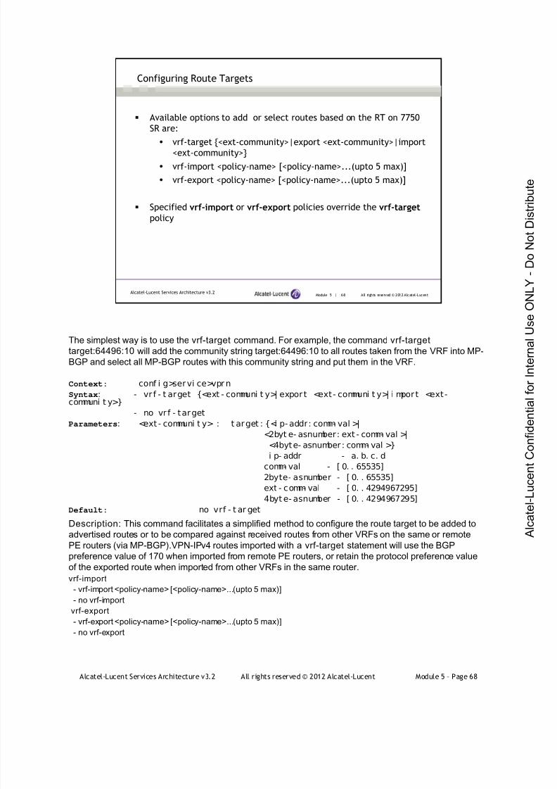
7/21/2019 Services Architecture v3.2 Student Guide Download
http://slidepdf.com/reader/full/services-architecture-v32-student-guide-download 344/429
Alcatel-Lucent Services Architecture v3.2 All rights reserved © 2012 Alcatel-Lucent Module 5 – Page 68
The simplest way is to use the vrf-target command. For example, the command vrf-target
target:64496:10 will add the community string target:64496:10 to all routes taken from the VRF into MP-
BGP and select all MP-BGP routes with this community string and put them in the VRF.
Context: conf i g>servi ce>vpr n
Syntax: - vr f - t arget {<ext - communi t y>| expor t <ext- communi t y>| i mpor t <ext-communi t y>}
- no vr f - targetParameters: <ext - communi t y> : t arget : {<i p- addr: comm- val >|
<2byt e- asnumber: ext - comm- val >|
<4byte- asnumber : comm- val >}
i p- addr - a. b. c. d
comm- val - [ 0. . 65535]
2byte- asnumber - [ 0. . 65535]
ext - comm- val - [ 0. . 4294967295]
4byt e- asnumber - [ 0. . 4294967295]
Default: no vrf - t ar get
Description: This command facilitates a simplified method to configure the route target to be added to
advertised routes or to be compared against received routes from other VRFs on the same or remote
PE routers (via MP-BGP).VPN-IPv4 routes imported with a vrf-target statement will use the BGP
preference value of 170 when imported from remote PE routers, or retain the protocol preference valueof the exported route when imported from other VRFs in the same router.
vrf-import
- vrf-import <policy-name> [<policy-name>...(upto 5 max)]
- no vrf-import
vrf-export
- vrf-export <policy-name> [<policy-name>...(upto 5 max)]
- no vrf-export
Module 5 | 68 All rights reserved © 2012 Alcatel-LucentAlcatel-Lucent Services Architecture v3.2
Configuring Route Targets
Available options to add or select routes based on the RT on 7750
SR are:
vrf-target {<ext-community>|export <ext-community>|import
<ext-community>}
vrf-import <policy-name> [<policy-name>...(upto 5 max)]
vrf-export <policy-name> [<policy-name>...(upto 5 max)]
Specified vrf-import or vrf-export policies override the vrf-targetpolicy

7/21/2019 Services Architecture v3.2 Student Guide Download
http://slidepdf.com/reader/full/services-architecture-v32-student-guide-download 345/429
Alcatel-Lucent Services Architecture v3.2 All rights reserved © 2012 Alcatel-Lucent Module 5 – Page 69
The route-distinguisher command sets the identifier attached to routes that distinguish the VPN they
belong to. Each routing instance must be associated with a unique (within the carrier’s domain) route
distinguisher. A route distinguisher must be defined for a VPRN to be operationally-active.
The vrf-target command facilitates a simplified method to configure the route target to be added to
advertised routes or compared against received routes from other VRFs on the same or remote PE
routers (using MP-BGP).
The vrf-target command does not allow multiple export or import route targets to be specified.
Module 5 | 69 All rights reserved © 2012 Alcatel-LucentAlcatel-Lucent Services Architecture v3.2
Configuring the Route Distinguisher and Route Target
PE1>conf i g>servi ce#vprn 10
PE1>conf i g>ser vi ce>vprn$ route-distinguisher 64496:1PE1>conf i g>ser vi ce>vprn$
It is mandatory to define a route distinguisher for the VPRN.
PE1>conf i g>servi ce#vprn 20PE1>conf i g>ser vi ce>vprn$ route-distinguisher 64496:2
PE1>conf i g>ser vi ce>vprn$
The route target will be added to advertised routes and compared to the
value contained in received routes.
PE1>conf i g>servi ce#vprn 10PE1>conf i g>ser vi ce>vprn$ vrf-target target:64496:10
PE1>conf i g>ser vi ce>vprn$
PE1>conf i g>servi ce#vprn 20PE1>conf i g>ser vi ce>vprn$ vrf-target target:64496:20
PE1>conf i g>ser vi ce>vprn$
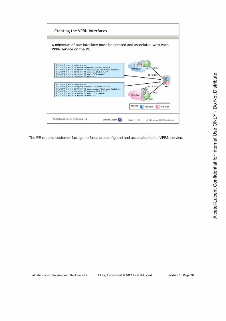
7/21/2019 Services Architecture v3.2 Student Guide Download
http://slidepdf.com/reader/full/services-architecture-v32-student-guide-download 346/429
Alcatel-Lucent Services Architecture v3.2 All rights reserved © 2012 Alcatel-Lucent Module 5 – Page 70
The PE routers’ customer-facing interfaces are configured and associated to the VPRN service.
Module 5 | 70 All rights reserved © 2012 Alcatel-LucentAlcatel-Lucent Services Architecture v3.2
Creating the VPRN Interfaces
A minimum of one interface must be created and associated with each
VPRN service on the PE.
PE1>confi g>ser vi ce# vprn 10
PE1>confi g>ser vi ce>vprn# interface "toCE1" create
PE1>confi g>ser vi ce>vprn>i f $ description "Customer BlueSite1"
PE1>confi g>ser vi ce>vprn>i f $ address 10.1.3.1/27
PE1>confi g>ser vi ce>vprn>i f $ sap 1/1/3 create
PE1>confi g>ser vi ce>vprn>i f $ exit all
PE1>confi g>ser vi ce# vprn 20
PE1>confi g>ser vi ce>vprn# interface "toCE3" create
PE1>confi g>ser vi ce>vprn>i f $ description "Customer RedSite1"
PE1>confi g>ser vi ce>vprn>i f $ address 10.1.6.1/27
PE1>confi g>ser vi ce>vprn>i f $ sap 1/1/2 create
PE1>confi g>ser vi ce>vprn>i f $ exit all
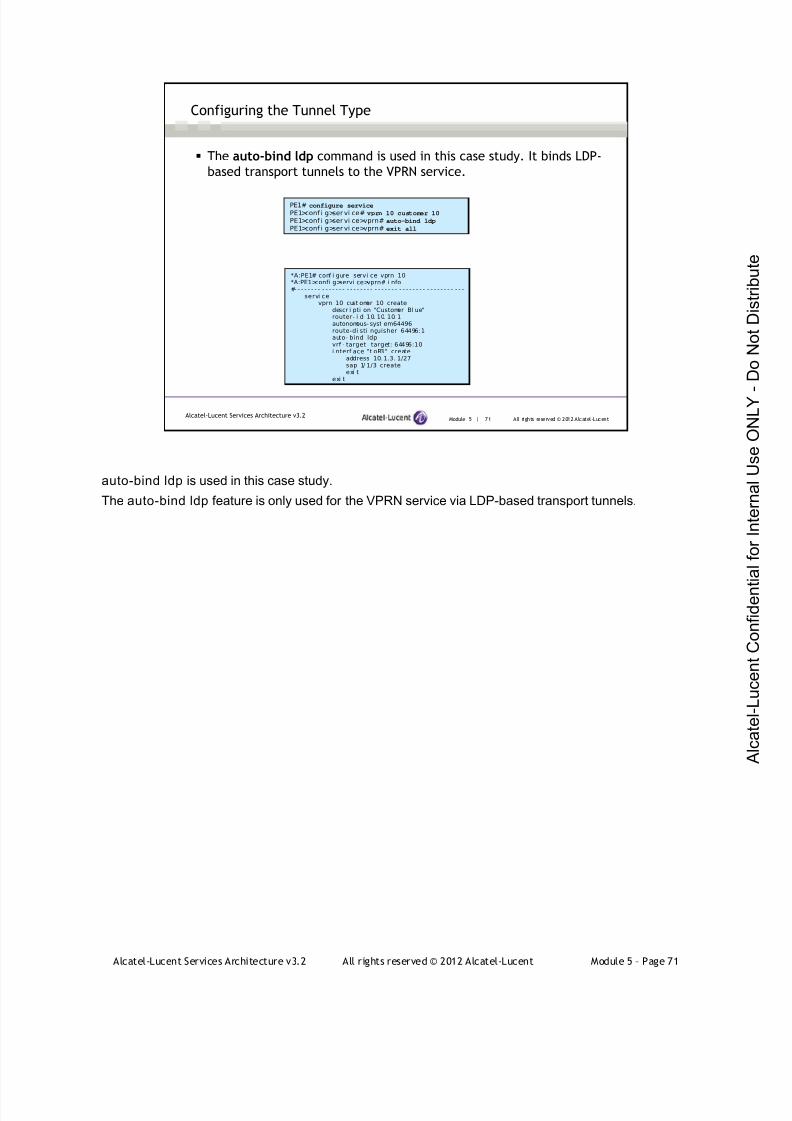
7/21/2019 Services Architecture v3.2 Student Guide Download
http://slidepdf.com/reader/full/services-architecture-v32-student-guide-download 347/429
Alcatel-Lucent Services Architecture v3.2 All rights reserved © 2012 Alcatel-Lucent Module 5 – Page 71
auto-bind ldp is used in this case study.
The auto-bind ldp feature is only used for the VPRN service via LDP-based transport tunnels.
Module 5 | 71 All rights reserved © 2012 Alcatel-LucentAlcatel-Lucent Services Architecture v3.2
Configuring the Tunnel Type
The auto-bind ldp command is used in this case study. It binds LDP-
based transport tunnels to the VPRN service.
PE1# configure service
PE1>conf i g>ser vi ce# vprn 10 customer 10
PE1>conf i g>ser vi ce>vprn# auto-bind ldp
PE1>conf i g>ser vi ce>vprn# exit all
*A:PE1# conf i gure servi ce vprn 10*A:PE1>confi g>servi ce>vprn# i nfo#- - - - - - - - - - - - - - - - - - - - - - - - - - - - - - - - - - - - - - - - - - - - - - - - -
servi cevprn 10 cust omer 10 create
descr i pti on "Customer Bl ue"router- i d 10. 10. 10. 1autonomous- syst em64496route-di sti nguisher 64496:1auto- bind ldpvrf - target target: 64496:10i nterf ace "t oR3" create
address 10. 1.3. 1/27sap 1/ 1/3 createexi t
exi t
7/21/2019 Services Architecture v3.2 Student Guide Download
http://slidepdf.com/reader/full/services-architecture-v32-student-guide-download 348/429
Alcatel-Lucent Services Architecture v3.2 All rights reserved © 2012 Alcatel-Lucent Module 5 – Page 72
Module 5 | 72 All rights reserved © 2012 Alcatel-LucentAlcatel-Lucent Services Architecture v3.2
Configuring PE to CE Routing
Select the PE to CE routing protocol (BGP is used in this case)
Configure the PE
Define the route policy on the PE
Configure the VPRN routing protocol
Configure the CE
Define the route policy on the CE (optional)
Configure BGP on the CE
The same PE-CE routing protocol is not mandatory for all sites
Static routing, RIP, OSPF, or BGP can be used as the PE-CE routing protocol. In this case study, BGP
will be used.
When BGP is used as the PE-CE routing protocol, PE and CE routers will become BGP peers. The CE
will use BGP to tell the PE router the set of address prefixes that are reachable at the router site of the
CE.
To configure BGP on the PE, the BGP instance must be created under the VPRN service context. The
CE is configured with a standard BGP instance, since it is not MPLS-aware.
When BGP is configured in the CE, care must be taken to ensure that address prefixes from other sites
(for example, address prefixes learned by the CE router from the PE router) are never displayed to the
PE. Specifically, if a PE router receives a VPN-IPv4 route and as a result distributes an IPv4 route to a
CE, then that route must not be distributed back from the site of the CE to a PE router, either from the
same or a different router.
This topic is discussed in further detail in the VPRN course.
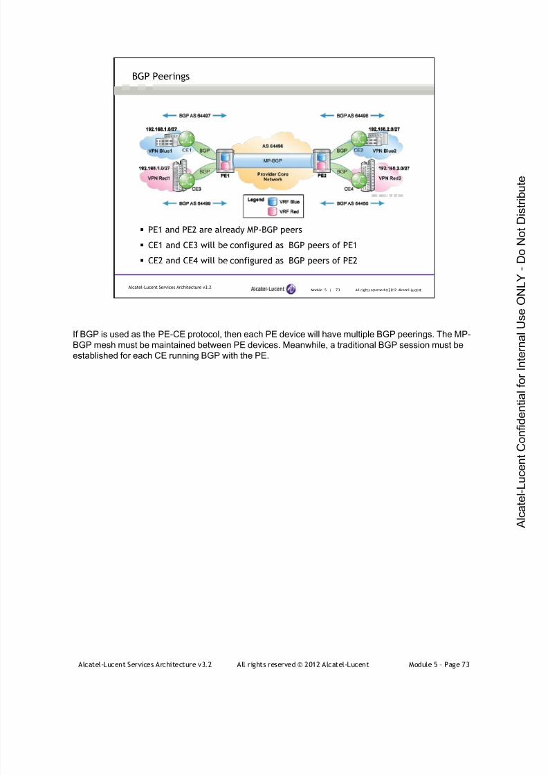
7/21/2019 Services Architecture v3.2 Student Guide Download
http://slidepdf.com/reader/full/services-architecture-v32-student-guide-download 349/429
Alcatel-Lucent Services Architecture v3.2 All rights reserved © 2012 Alcatel-Lucent Module 5 – Page 73
Module 5 | 73 All r ights reserved ©2012 Alcatel-LucentAlcatel-Lucent Services Architecture v3.2
BGP Peerings
PE1 and PE2 are already MP-BGP peers
CE1 and CE3 will be configured as BGP peers of PE1
CE2 and CE4 will be configured as BGP peers of PE2
If BGP is used as the PE-CE protocol, then each PE device will have multiple BGP peerings. The MP-
BGP mesh must be maintained between PE devices. Meanwhile, a traditional BGP session must be
established for each CE running BGP with the PE.

7/21/2019 Services Architecture v3.2 Student Guide Download
http://slidepdf.com/reader/full/services-architecture-v32-student-guide-download 350/429
Alcatel-Lucent Services Architecture v3.2 All rights reserved © 2012 Alcatel-Lucent Module 5 – Page 74
Policy must be defined to allow the exchange of routes from MP-BGP into the configured PE-CE
protocol. The route policy can be applied as an import policy or an export policy. The policies must be
defined before they can be applied.
Routes that belong to a VPRN must use the protocol owner, VPN-IPv4, to denote that it is a VPRN
route. This can be used within the route policy match criteria.
.
Module 5 | 74 All rights reserved © 2012 Alcatel-LucentAlcatel-Lucent Services Architecture v3.2
Defining the PE-CE Route Policy on the PE
VPN route exchange from MP-BGP to BGP is controlled by policy.
*A: PE1>conf i g>router>pol i cy-opti ons# i nfo- - - - - - - - - - - - - - - - - - - - - - - - - - - - - - - - - - - - - - - - - - - - - -
pol i cy- st at ement "mpbgp- bgp"ent ry 10
f romprotocol bgp-vpn
exi tacti on acceptexi t
exi texi t
- - - - - - - - - - - - - - - - - - - - - - - - - - - - - - - - - - - - - - - - - - - - - -
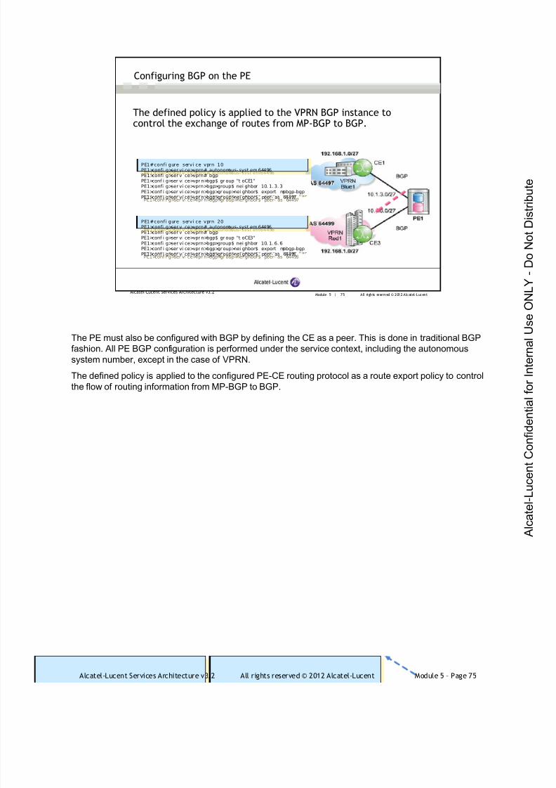
7/21/2019 Services Architecture v3.2 Student Guide Download
http://slidepdf.com/reader/full/services-architecture-v32-student-guide-download 351/429
Alcatel-Lucent Services Architecture v3.2 All rights reserved © 2012 Alcatel-Lucent Module 5 – Page 75
The PE must also be configured with BGP by defining the CE as a peer. This is done in traditional BGP
fashion. All PE BGP configuration is performed under the service context, including the autonomous
system number, except in the case of VPRN.
The defined policy is applied to the configured PE-CE routing protocol as a route export policy to control
the flow of routing information from MP-BGP to BGP.
Module 5 | 75 All rights reserved © 2012 Alcatel-LucentAlcatel-Lucent Services Architecture v3.2
Configuring BGP on the PE
The defined policy is applied to the VPRN BGP instance tocontrol the exchange of routes from MP-BGP to BGP.
PE1#confi gure servi ce vprn 10PE1>confi g>ser vi ce>vprn# autonomous- syst em64496PE1>confi g>ser vi ce>vprn# bgpPE1>conf i g>ser vi ce>vpr n>bgp$ gr oup "t oCE1"PE1>confi g>ser vi ce>vprn>bgp>group$ nei ghbor 10. 1. 3. 3PE1>conf i g>ser vi ce>vpr n>bgp>gr oup>nei ghbor$ export mpbgp-bgpPE1>conf i g>ser vi ce>vpr n>bgp>gr oup>nei ghbor$ peer- as 64497
PE1#confi gure servi ce vprn 10PE1>confi g>ser vi ce>vprn# autonomous- syst em 64496PE1>confi g>ser vi ce>vprn# bgpPE1>conf i g>ser vi ce>vpr n>bgp$ gr oup "t oCE1"PE1>confi g>ser vi ce>vprn>bgp>group$ nei ghbor 10. 1. 3. 3PE1>conf i g>ser vi ce>vpr n>bgp>group>nei ghbor$ export mpbgp-bgpPE1>conf i g>ser vi ce>vpr n>bgp>group>nei ghbor$ peer- as 64497
PE1#confi gure servi ce vprn 20PE1>confi g>ser vi ce>vprn# autonomous- syst em64496PE1>confi g>ser vi ce>vprn# bgpPE1>conf i g>ser vi ce>vpr n>bgp$ gr oup "t oCE3"PE1>confi g>ser vi ce>vprn>bgp>group$ nei ghbor 10. 1. 6. 6PE1>conf i g>ser vi ce>vpr n>bgp>gr oup>nei ghbor$ export mpbgp-bgpPE1>conf i g>ser vi ce>vpr n>bgp>gr oup>nei ghbor$ peer- as 64499
PE1#confi gure servi ce vprn 20PE1>confi g>ser vi ce>vprn# autonomous- syst em 64496PE1>confi g>ser vi ce>vprn# bgpPE1>conf i g>ser vi ce>vpr n>bgp$ gr oup "t oCE3"PE1>confi g>ser vi ce>vprn>bgp>group$ nei ghbor 10. 1. 6. 6PE1>conf i g>ser vi ce>vpr n>bgp>group>nei ghbor$ export mpbgp-bgpPE1>conf i g>ser vi ce>vpr n>bgp>group>nei ghbor$ peer- as 64499
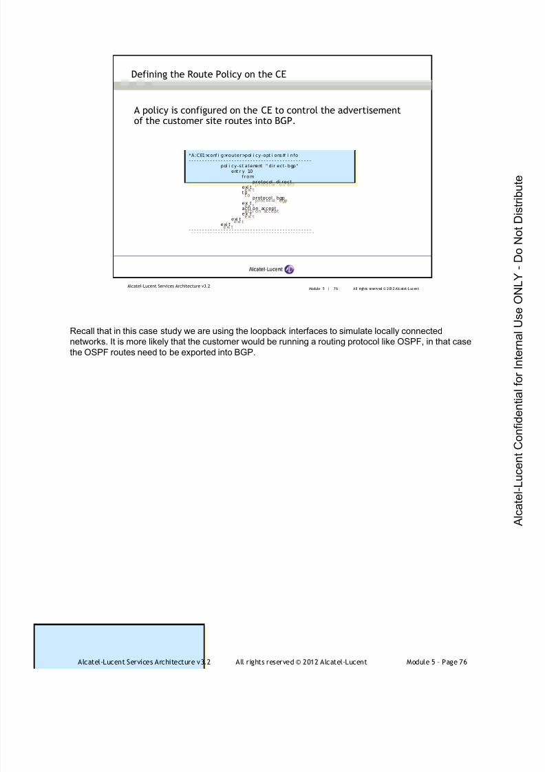
7/21/2019 Services Architecture v3.2 Student Guide Download
http://slidepdf.com/reader/full/services-architecture-v32-student-guide-download 352/429
Alcatel-Lucent Services Architecture v3.2 All rights reserved © 2012 Alcatel-Lucent Module 5 – Page 76
Recall that in this case study we are using the loopback interfaces to simulate locally connected
networks. It is more likely that the customer would be running a routing protocol like OSPF, in that case
the OSPF routes need to be exported into BGP.
Module 5 | 76 All rights reserved © 2012 Alcatel-LucentAlcatel-Lucent Services Architecture v3.2
Defining the Route Policy on the CE
A policy is configured on the CE to control the advertisementof the customer site routes into BGP.
*A:CE1>conf i g>router>pol i cy-opti ons# i nfo- - - - - - - - - - - - - - - - - - - - - - - - - - - - - - - - - - - - - - - - - - - - - -
pol i cy-st atement " dir ect- bgp"ent ry 10
f romprotocol dir ect
exi tt o
prot ocol bgpexi tacti on acceptexi t
exi texi t
- - - - - - - - - - - - - - - - - - - - - - - - - - - - - - - - - - - - - - - - - - - - - -
*A:CE1>conf i g>router>pol i cy-opt i ons# i nfo- - - - - - - - - - - - - - - - - - - - - - - - - - - - - - - - - - - - - - - - - - - - - -
pol i cy-st atement " dir ect- bgp"ent r y 10
f romprotocol di rect
exi tt o
protocol bgpexi tacti on acceptexi t
exi texi t
- - - - - - - - - - - - - - - - - - - - - - - - - - - - - - - - - - - - - - - - - - - - - -

7/21/2019 Services Architecture v3.2 Student Guide Download
http://slidepdf.com/reader/full/services-architecture-v32-student-guide-download 353/429
Alcatel-Lucent Services Architecture v3.2 All rights reserved © 2012 Alcatel-Lucent Module 5 – Page 77
The CE will be configured with BGP as the routing protocol, as shown in the slide.
Note: the autonomous system is defined in the global context and a policy is specified to control the set
of prefixes exchanged with peers.
Module 5 | 77 All rights reserved © 2012 Alcatel-LucentAlcatel-Lucent Services Architecture v3.2
Configuring the CE for BGP
CE1# configure router
CE1>conf i g>r outer # autonomous-system 64497
CE1>conf i g>r outer # bgpCE1>conf i g>r out er>bgp$ group “toPE1"
CE1>conf i g>r out er>bgp>gr oup$ peer-as 64496CE1>conf i g>r out er>bgp>gr oup$ neighbor 10.1.3.1
CE1>conf i g>r out er>bgp>gr oup$ export "direct-to-bgp"
CE1>conf i g>r out er>bgp>gr oup>nei ghbor$ exit all
CE1# configure routerCE1>conf i g>r outer # autonomous-system 64497
CE1>conf i g>r outer # bgpCE1>conf i g>r out er>bgp$ group “toPE1"
CE1>conf i g>r out er>bgp>group$ peer-as 64496CE1>conf i g>r out er>bgp>group$ neighbor 10.1.3.1
CE1>conf i g>r out er>bgp>group$ export "direct-to-bgp"
CE1>conf i g>r out er>bgp>group>nei ghbor$ exit all
Configure the CE for BGP with the specified route policy applied.
CE3# configure router
CE3>conf i g>r outer # autonomous-system 64499
CE3>conf i g>r outer # bgpCE3>conf i g>r outer >bgp$ group “toPE1"
CE3>conf i g>r outer >bgp>group$ peer-as 64496CE3>conf i g>r outer >bgp>group$ neighbor 10.1.6.1
CE3>conf i g>r outer >bgp>group$ export "direct-to-bgp"
CE3>conf i g>r outer >bgp>group>nei ghbor$ exit all
CE3# configure router
CE3>confi g>r outer # autonomous-system 64499
CE3>confi g>r outer # bgpCE3>conf i g>r outer>bgp$ group “toPE1"
CE3>conf i g>r outer>bgp>group$ peer-as 64496CE3>conf i g>r outer>bgp>group$ neighbor 10.1.6.1
CE3>conf i g>r outer>bgp>group$ export "direct-to-bgp"
CE3>conf i g>r outer>bgp>group>nei ghbor$ exit all

7/21/2019 Services Architecture v3.2 Student Guide Download
http://slidepdf.com/reader/full/services-architecture-v32-student-guide-download 354/429
Alcatel-Lucent Services Architecture v3.2 All rights reserved © 2012 Alcatel-Lucent Module 5 – Page 78
Module 5 | 78 All rights reserved © 2012 Alcatel-LucentAlcatel-Lucent Services Architecture v3.2
Verifying BGP Peering
A:PE1# show router 10 bgp summary===============================================================================BGP Router I D: 10. 10. 10.1 AS: 64496 Local AS: 64496
===============================================================================BGP Admin State : Up BGP Oper State : Up
Tot al Peer Gr oups : 1 Total Peers : 1 Tot al BGP Pat hs : 4 Total Pat h Memory : 512 Tot al I Pv4 Remot e Rts : 3 Total I Pv4 Rem. Act i ve Rts : 2 Tot al I Pv6 Remot e Rts : 0 Total I Pv6 Rem. Act i ve Rts : 0 Tot al Supressed Rts : 0 Total Hi st . Rts : 0 Tot al Decay Rts : 0
===============================================================================BGP Summar y===============================================================================Nei ghbor
AS PktRcvd I nQ Up/Down State| Rcv/Act/ Sent (Addr Fami l y)PktSent OutQ
- - - - - - - - - - - - - - - - - - - - - - - - - - - - - - - - - - - - - - - - - - - - - - - - - - - - - - - - - - - - - - - - - - - - - - - - - - - - - - -10.1.3.3
64497 13750 0 04d19h23m 3/ 2/ 3 ( I Pv4)13845 0
A:PE1# show router 10 bgp summary
===============================================================================BGP Router I D: 10. 10. 10. 1 AS:64496 Local AS: 64496
===============================================================================BGP Admin State : Up BGP Oper State : Up
Total Peer Gr oups : 1 Total Peers : 1 Total BGP Pat hs : 4 Total Pat h Memory : 512 Total I Pv4 Remot e Rts : 3 Total I Pv4 Rem. Act i ve Rts : 2 Total I Pv6 Remot e Rts : 0 Total I Pv6 Rem. Act i ve Rts : 0 Total Supressed Rts : 0 Total Hi st . Rts : 0 Total Decay Rts : 0
===============================================================================BGP Summar y===============================================================================Nei ghbor
AS PktRcvd I nQ Up/Down State|Rcv/Act/ Sent (Addr Fami l y)PktSent OutQ
- - - - - - - - - - - - - - - - - - - - - - - - - - - - - - - - - - - - - - - - - - - - - - - - - - - - - - - - - - - - - - - - - - - - - - - - - - - - - - -10.1.3.3
64497 13750 0 04d19h23m 3/ 2/ 3 ( I Pv4)13845 0
When issued from the PE, the CE should appear as a BGP neighbor under the show router <service
id> bgp summary command.
The details of the CE-PE BGP neighbor relationship will be visible under the show router <service id>
bgp neighbor command.
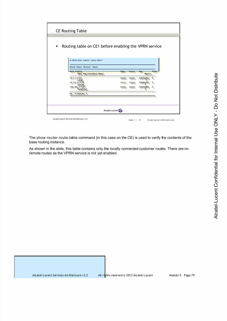
7/21/2019 Services Architecture v3.2 Student Guide Download
http://slidepdf.com/reader/full/services-architecture-v32-student-guide-download 355/429
Alcatel-Lucent Services Architecture v3.2 All rights reserved © 2012 Alcatel-Lucent Module 5 – Page 79
Module 5 | 79 All rights reserved © 2012 Alcatel-LucentAlcatel-Lucent Services Architecture v3.2
Routing table on CE1 before enabling the VPRN service
CE Routing Table
A:CE1# show router route-table
===============================================================================
Route Table (Router: Base)
===============================================================================
Dest Prefix Type Proto Age Pref
Next Hop[Interface Name] Metric
-------------------------------------------------------------------------------
10.1.3.0/27 Local Local 01h35m30s 0
toPE1 0
10.10.10.3/32 Local Local 05d04h01m 0
system 0
192.168.1.0/27 Local Local 01h14m50s 0
BlueSite1 0
-------------------------------------------------------------------------------
No. of Routes: 6
===============================================================================
The show router route-table command (in this case on the CE) is used to verify the contents of the
base routing instance.
As shown in the slide, this table contains only the locally connected customer routes. There are no
remote routes as the VPRN service is not yet enabled.

7/21/2019 Services Architecture v3.2 Student Guide Download
http://slidepdf.com/reader/full/services-architecture-v32-student-guide-download 356/429
Alcatel-Lucent Services Architecture v3.2 All rights reserved © 2012 Alcatel-Lucent Module 5 – Page 80
Module 5 | 80 All r ights reserved ©2012 Alcatel-LucentAlcatel-Lucent Services Architecture v3.2
Complete the VPRN service configuration on PE1 forCustomer Blue.
Enabling the VPRN Service
*A:PE1# conf i gure servi ce vprn 10*A: PE1>confi g>servi ce>vprn# i nfo#- - - - - - - - - - - - - - - - - - - - - - - - - - - - -- - - - - - - - - - - - - - - - - - - - -
servi cevprn 10 customer 10 create
descri pti on "Cust omer Bl ue"router- i d 10. 10. 10. 1autonomous- syst em64496route-di sti nguisher 64496:1auto- bind ldpvrf -t arget target: 64496:10i nterf ace "t oR3" create
address 10.1. 3.1/ 27sap 1/ 1/3 createexi t
exi tbgp
group "t oCE1"neighbor 10.1.3.3
export "mbgp- bgp"peer- as 64497
exi texi t
exi tno shut down
*A:PE1# conf i gure servi ce vprn 10*A: PE1>confi g>servi ce>vprn# i nfo#- - - - - - - - - - - - - - - - - - - - - - - - - - - - - - - - - - - - - - - - - - - - - - - - - -
servi cevprn 10 customer 10 create
descri pti on "Customer Bl ue"router- i d 10. 10. 10. 1autonomous- syst em64496route-di sti nguisher 64496:1auto- bind ldpvrf -t arget target: 64496:10i nterf ace "t oR3" create
address 10.1.3. 1/27sap 1/ 1/3 createexi t
exi tbgp
group "t oCE1"neighbor 10. 1.3.3
export "mbgp- bgp"peer- as 64497
exi texi t
exi tno shut down
To enable the VPRN service, no shutdown command is used. The slide shows the complete VPRN
configuration on PE1 for customer Blue. Similar configurations are on PE2 as shown below:
- - - - - - - - - - - - - - - - - - - - - - - - - - - - - - - - - - - - - - - -
vpr n 10 cust omer 10 create
descri pt i on "Cust omer Bl ue"
r out er - i d 10. 10. 10. 2
aut onomous- syst em 64496r out e- di st i ngui sher 64496: 1
aut o- bi nd l dp
vrf - t ar get t ar get : 64496: 10
i nt er f ace "t oR4" cr eat e
addr ess 10. 2. 4. 2/ 27
sap 1/ 1/ 3 cr eat e
exi t
exi t
bgp
group "t oCE2"
nei ghbor 10. 2. 4. 4expor t "mbgp- bgp"
peer - as 64498
exi t
exi t
exi t
no shutdown
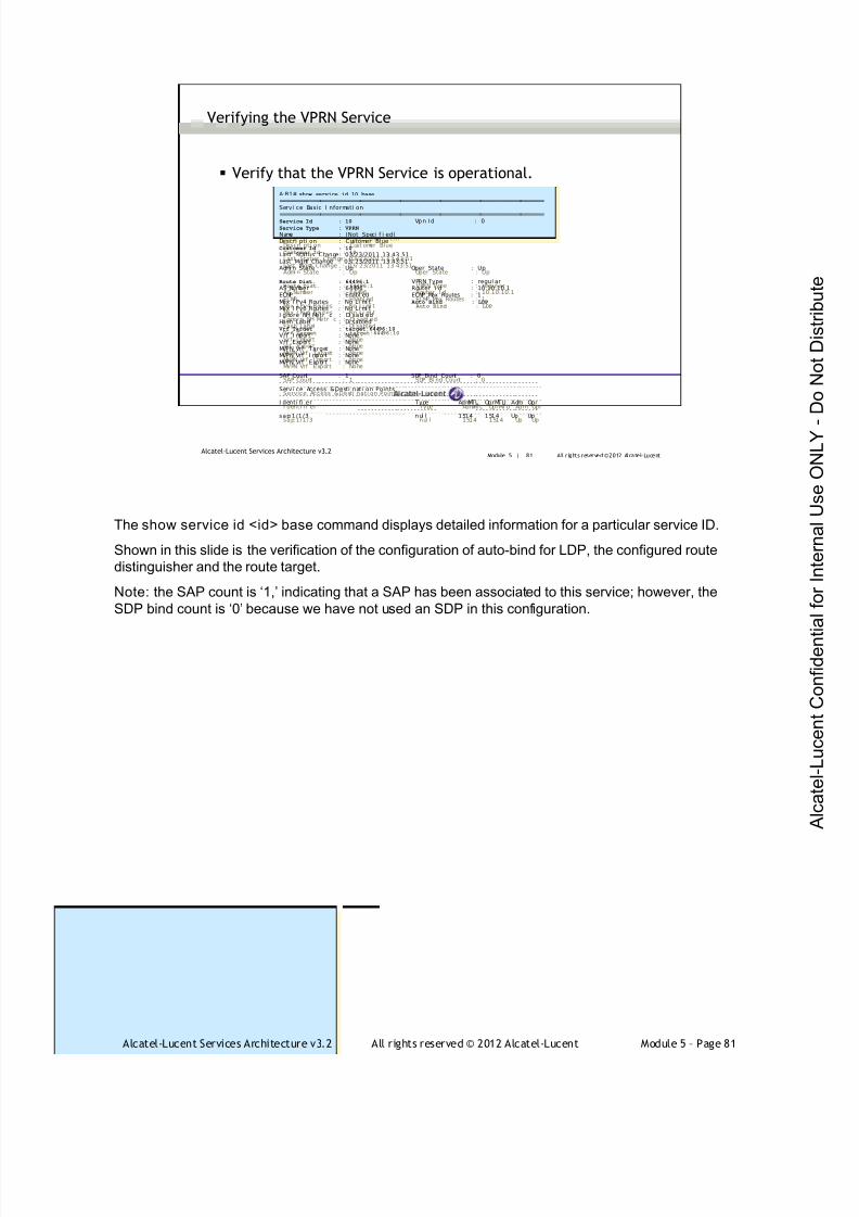
7/21/2019 Services Architecture v3.2 Student Guide Download
http://slidepdf.com/reader/full/services-architecture-v32-student-guide-download 357/429
Alcatel-Lucent Services Architecture v3.2 All rights reserved © 2012 Alcatel-Lucent Module 5 – Page 81
Module 5 | 81 All r ights reserved ©2012 Alcatel-LucentAlcatel-Lucent Services Architecture v3.2
Verify that the VPRN Service is operational.
Verifying the VPRN Service
A:R1# show service id 10 base
===============================================================================
Service Basi c I nformati on===============================================================================Service Id : 10 Vpn Id : 0Service Type : VPRN
Name : (Not Speci f i ed)Descri pti on : Cust omer BlueCustomer Id : 10
Last Status Change: 03/23/2011 13: 43:51Last Mgmt Change : 03/ 23/2011 13: 43:51Admi n State : Up Oper State : Up
Route Dist. : 64496:1 VPRN Type : regul arAS Number : 64496 Router I d : 10.10.10.1ECMP : Enabl ed ECMP Max Routes : 1Max I Pv4 Routes : No Li mi t Auto Bind : LDP
Max I Pv6 Routes : No Li mi tI gnore NH Metri c : Di sabl edHash Label : Di sabled
Vrf Target : target:64496:10
Vrf I mport : NoneVrf Export : NoneMVPN Vrf Target : NoneMVPN Vrf I mport : NoneMVPN Vrf Export : None
SAP Count : 1 SDP Bi nd Count : 0- - - - - - - - - - - - -- - - - - - - - - - - -- - - - - - - - - - - -- - - - - - - - - - - -- - - - - - - - - - -- - - - - - - - - - - -- - - - - - -Service Access &Desti nati on Points- - - - - - - - - - - - -- - - - - - - - - - - -- - - - - - - - - - - -- - - - - - - - - - - -- - - - - - - - - - -- - - - - - - - - - - -- - - - - - -I denti fi er Type AdmMTU OprMTU Adm Opr- - - - - - - - - - - - -- - - - - - - - - - - -- - - - - - - - - - - -- - - - - - - - - - - -- - - - - - - - - - -- - - - - - - - - - - -- - - - - - -sap:1/1/3 nul l 1514 1514 Up Up
A:R1# show service id 10 base
===============================================================================Servi ce Basic I nformati on
===============================================================================Service Id : 10 Vpn Id : 0Service Type : VPRN
Name : (Not Speci f i ed)Descri pti on : Customer BlueCustomer Id : 10
Last Status Change: 03/23/2011 13: 43: 51Last Mgmt Change : 03/ 23/2011 13: 43:51Admi n State : Up Oper State : Up
Route Dist. : 64496:1 VPRN Type : regul arAS Number : 64496 Router I d : 10.10.10.1ECMP : Enabl ed ECMP Max Routes : 1Max I Pv4 Routes : No Li mi t Auto Bind : LDP
Max I Pv6 Routes : No Li mi tI gnore NH Metri c : Di sabl edHash Label : Di sabled
Vrf Target : target:64496:10
Vrf I mport : NoneVrf Export : NoneMVPN Vrf Target : NoneMVPN Vrf I mport : NoneMVPN Vrf Export : None
SAP Count : 1 SDP Bind Count : 0- - - - - - - - - - - -- - - - - - - - - - - -- - - - - - - - - - - -- - - - - - - - - - - -- - - - - - - - - - - -- - - - - - - - - - - -- - - - - - -Servi ce Access &Desti nati on Points- - - - - - - - - - - -- - - - - - - - - - - -- - - - - - - - - - - -- - - - - - - - - - - -- - - - - - - - - - - -- - - - - - - - - - - -- - - - - - -I denti fi er Type AdmMTU OprMTU Adm Opr- - - - - - - - - - - -- - - - - - - - - - - -- - - - - - - - - - - -- - - - - - - - - - - -- - - - - - - - - - - -- - - - - - - - - - - -- - - - - - -sap:1/1/3 nul l 1514 1514 Up Up
The show service id <id> base command displays detailed information for a particular service ID.
Shown in this slide is the verification of the configuration of auto-bind for LDP, the configured route
distinguisher and the route target.
Note: the SAP count is ‘1,’ indicating that a SAP has been associated to this service; however, the
SDP bind count is ‘0’ because we have not used an SDP in this configuration.
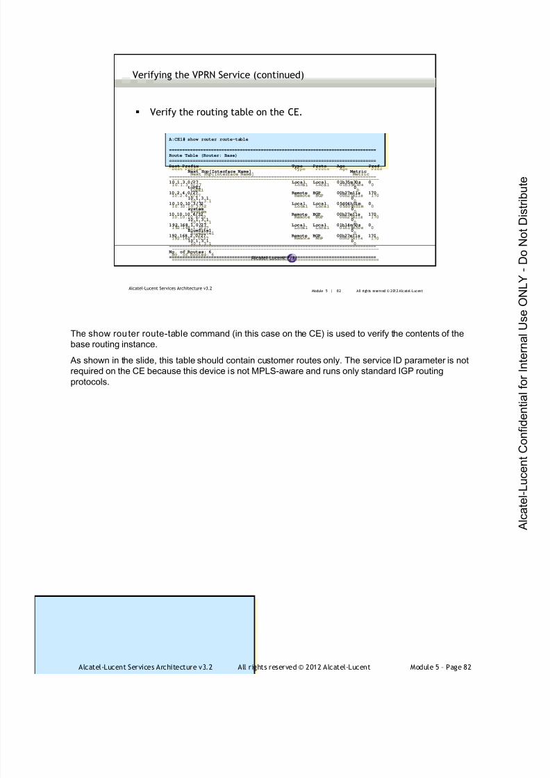
7/21/2019 Services Architecture v3.2 Student Guide Download
http://slidepdf.com/reader/full/services-architecture-v32-student-guide-download 358/429
Alcatel-Lucent Services Architecture v3.2 All rights reserved © 2012 Alcatel-Lucent Module 5 – Page 82
Module 5 | 82 All rights reserved © 2012 Alcatel-LucentAlcatel-Lucent Services Architecture v3.2
A:CE1# show router route-table
===============================================================================
Route Table (Router: Base)
===============================================================================
Dest Prefix Type Proto Age Pref
Next Hop[Interface Name] Metric
-------------------------------------------------------------------------------
10.1.3.0/27 Local Local 01h35m30s 0
toPE1 0
10.2.4.0/27 Remote BGP 00h27m11s 170
10.1.3.1 0
10.10.10.3/32 Local Local 05d04h01m 0
system 0
10.10.10.4/32 Remote BGP 00h27m11s 170
10.1.3.1 0
192.168.1.0/27 Local Local 01h14m50s 0
BlueSite1 0
192.168.2.0/27 Remote BGP 00h27m11s 170
10.1.3.1 0
-------------------------------------------------------------------------------
No. of Routes: 6
===============================================================================
Verify the routing table on the CE.
Verifying the VPRN Service (continued)
The show router route-table command (in this case on the CE) is used to verify the contents of the
base routing instance.
As shown in the slide, this table should contain customer routes only. The service ID parameter is not
required on the CE because this device is not MPLS-aware and runs only standard IGP routing
protocols.

7/21/2019 Services Architecture v3.2 Student Guide Download
http://slidepdf.com/reader/full/services-architecture-v32-student-guide-download 359/429
Alcatel-Lucent Services Architecture v3.2 All rights reserved © 2012 Alcatel-Lucent Module 5 – Page 83
Module 5 | 83 All rights reserved © 2012 Alcatel-LucentAlcatel-Lucent Services Architecture v3.2
A:PE1# show router 10 route-table
===============================================================================
Route Table (Service: 1)
===============================================================================
Dest Prefix Type Proto Age Pref
Next Hop[Interface Name] Metric
-------------------------------------------------------------------------------
10.1.3.0/27 Local Local 00h26m35s 0
toCE1 0
10.2.4.0/27 Remote BGP VPN 00h40m13s 170
10.10.10.2 (tunneled) 0
10.10.10.3/32 Remote BGP 00h25m45s 170
10.1.3.3 0
10.10.10.4/32 Remote BGP VPN 00h39m29s 170
10.10.10.2 (tunneled) 0
192.168.1.0/27 Remote BGP 00h25m45s 170
10.1.3.3 0
192.168.2.0/27 Remote BGP VPN 00h39m29s 170
10.10.10.2 (tunneled) 0
-------------------------------------------------------------------------------
No. of Routes: 6
===============================================================================
Verify the VPRN service’s routing table on the PE.
Verifying the VPRN Service (continued)
The show router <service-id> route-table command is used to verify the contents of the routing
instance for the specified service.
As shown in the slide, this table should contain customer routes such as physical links to the PE
devices, system interfaces of the CE devices, and internal customer LAN networks.
The prefixes received from the local CE will be learned from the configured PE-CE protocol (BGP), while
the prefixes received from the remote CE will be learned from the BGP VPN (MP-BGP) protocol.

7/21/2019 Services Architecture v3.2 Student Guide Download
http://slidepdf.com/reader/full/services-architecture-v32-student-guide-download 360/429
Alcatel-Lucent Services Architecture v3.2 All rights reserved © 2012 Alcatel-Lucent Module 5 – Page 84
Module 5 | 84 All r ights reserved ©2012 Alcatel-LucentAlcatel-Lucent Services Architecture v3.2
Verifying the VPRN Service (continued)
Verify the MPLS labels with an active binding
The label owned by VPRN is the VPN label for the service.
The label owned by LDP is the transport tunnel label for the service.
If RSVP were configured, the label owned by RSVP would be the LSPlabel.
A: PE1#show router mpls l abel 32 131071 i n-use
=================================================================MPLS Label s f r om32 to 131071 (I n-use)=================================================================Label Label Type Label Owner- - - - - - - - - - - - - - - - - - - - - - - - - - - - - - - - - - - - - - - - - - - - - - - - - - - - - - - - - - - - - - - - -131068 dynami c VPRN131069 dynami c VPRN131070 dynami c I LDP131071 dynami c I LDP- - - - - - - - - - - - - - - - - - - - - - - - - - - - - - - - - - - - - - - - - - - - - - - - - - - - - - - - - - - - - - - - -I n-use l abels (Owner: Al l ) i n speci f i ed range : 4I n-use l abels i n enti re range : 4=================================================================
A: PE1# show router mpls l abel 32 131071 i n-use
=================================================================MPLS Label s f rom 32 to 131071 (I n-use)=================================================================Label Label Type Label Owner- - - - - - - - - - - - - - - - - - - - - - - - - - - - - - - - - - - - - - - - - - - - - - - - - - - - - - - - - - - - - - - - -131068 dynami c VPRN131069 dynami c VPRN131070 dynami c I LDP131071 dynami c I LDP- - - - - - - - - - - - - - - - - - - - - - - - - - - - - - - - - - - - - - - - - - - - - - - - - - - - - - - - - - - - - - - - -I n-use l abels (Owner: Al l ) i n speci f i ed range : 4I n-use l abels i n enti re range : 4=================================================================
The show router mpls label command displays the bindings of the in-use MPLS labels and their
owner. In this case, there should be labels bound to LDP as a result of the transport tunnel signaling
and labels bound to the VPRN as a result of MP-BGP service label signaling.
ILDP is an interface LDP and refers to the transport tunnel (LSP) label, while VPRN refers to the inner
(VPN) label.
Although it is considered optional to configure MPLS when using LDP as the label signaling protocol,
any show router mpls command can be available when MPLS is enabled.
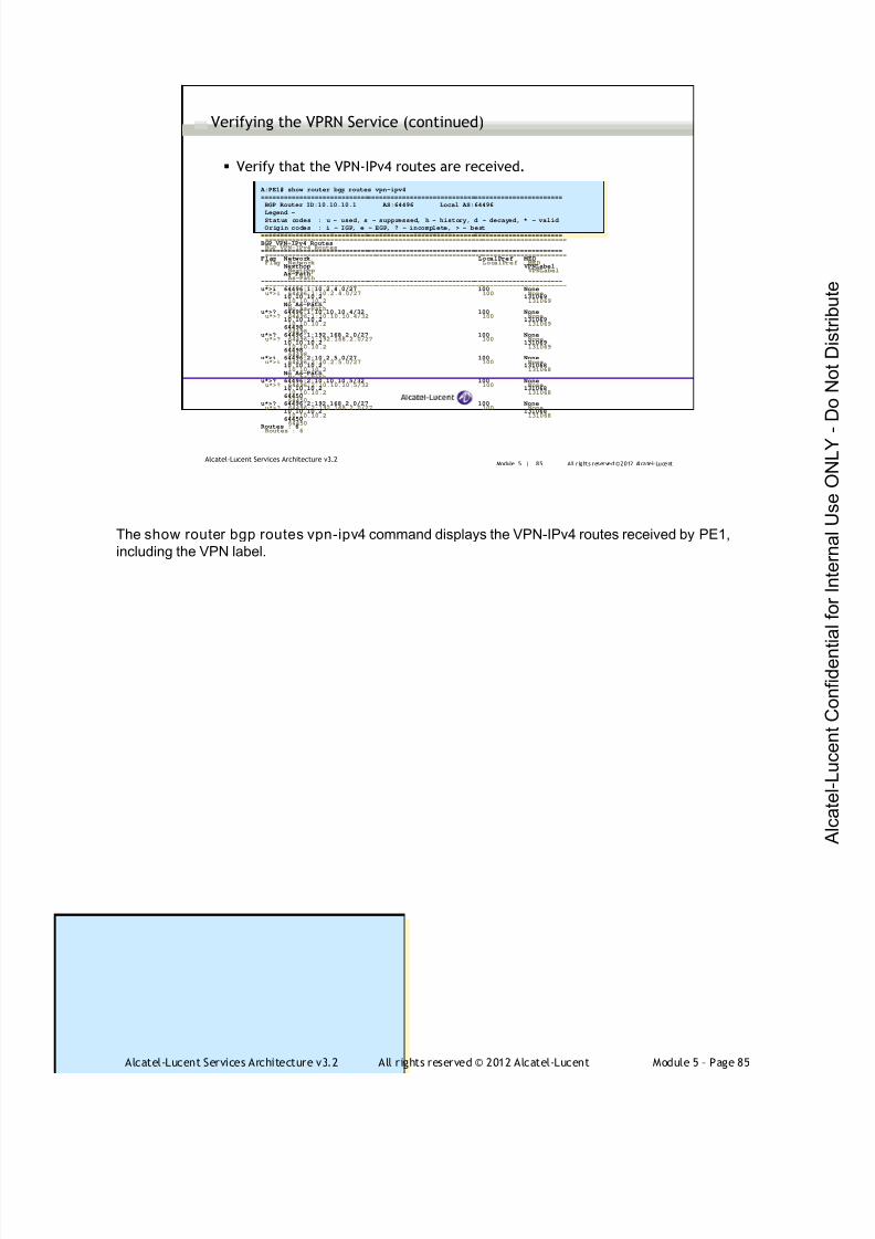
7/21/2019 Services Architecture v3.2 Student Guide Download
http://slidepdf.com/reader/full/services-architecture-v32-student-guide-download 361/429
Alcatel-Lucent Services Architecture v3.2 All rights reserved © 2012 Alcatel-Lucent Module 5 – Page 85
Module 5 | 85 All r ights reserved ©2012 Alcatel-LucentAlcatel-Lucent Services Architecture v3.2
Verifying the VPRN Service (continued)
Verify that the VPN-IPv4 routes are received.
A:PE1# show router bgp routes vpn-ipv4
===============================================================================
BGP Router ID:10.10.10.1 AS:64496 Local AS:64496
Legend -Status codes : u - used, s - suppressed, h - history, d - decayed, * - valid
Origin codes : i - IGP, e - EGP, ? - incomplete, > - best
===============================================================================
BGP VPN-IPv4 Routes
===============================================================================
Flag Network LocalPref MED
Nexthop VPNLabel
As-Path
-------------------------------------------------------------------------------
u*>i 64496:1:10.2.4.0/27 100 None
10.10.10.2 131069
No As-Path
u*>? 64496:1:10.10.10.4/32 100 None
10.10.10.2 131069
64498
u*>? 64496:1:192.168.2.0/27 100 None
10.10.10.2 131069
64498
u*>i 64496:2:10.2.5.0/27 100 None
10.10.10.2 131068
No As-Path
u*>? 64496:2:10.10.10.5/32 100 None
10.10.10.2 131068
64450
u*>? 64496:2:192.168.2.0/27 100 None
10.10.10.2 131068
64450
Routes : 6
A:PE1# show router bgp routes vpn-ipv4
===============================================================================
BGP Router ID:10.10.10.1 AS:64496 Local AS:64496
Legend -
Status codes : u - used, s - suppressed, h - history, d - decayed, * - valid
Origin codes : i - IGP, e - EGP, ? - incomplete, > - best
===============================================================================
BGP VPN-IPv4 Routes
===============================================================================
Flag Network LocalPref MED
Nexthop VPNLabel
As-Path
-------------------------------------------------------------------------------
u*>i 64496:1:10.2.4.0/27 100 None
10.10.10.2 131069
No As-Path
u*>? 64496:1:10.10.10.4/32 100 None
10.10.10.2 131069
64498
u*>? 64496:1:192.168.2.0/27 100 None
10.10.10.2 131069
64498
u*>i 64496:2:10.2.5.0/27 100 None
10.10.10.2 131068
No As-Path
u*>? 64496:2:10.10.10.5/32 100 None
10.10.10.2 131068
64450
u*>? 64496:2:192.168.2.0/27 100 None
10.10.10.2 131068
64450
Routes : 6
The show router bgp routes vpn-ipv4 command displays the VPN-IPv4 routes received by PE1,
including the VPN label.

7/21/2019 Services Architecture v3.2 Student Guide Download
http://slidepdf.com/reader/full/services-architecture-v32-student-guide-download 362/429
Alcatel-Lucent Services Architecture v3.2 All rights reserved © 2012 Alcatel-Lucent Module 5 – Page 86
Module 5 | 86 All r ights reserved ©2012 Alcatel-LucentAlcatel-Lucent Services Architecture v3.2
Verifying the VPRN Service (continued)
Verify the IP and MPLS forwarding information.
A:PE1# show router 10 fib 1===============================================================================
FIB Display
===============================================================================
Prefix Protocol
NextHop
-------------------------------------------------------------------------------
10.1.3.0/27 LOCAL
10.1.3.0 (toCE1)
10.2.4.0/27 BGP_VPN
10.10.10.2 (VPRN Label:131069 Transport:LDP)
10.10.10.3/32 BGP
10.1.3.3 Indirect (toCE1)
10.10.10.4/32 BGP_VPN
10.10.10.2 (VPRN Label:131069 Transport:LDP)
192.168.1.0/27 BGP
10.1.3.3 Indirect (toCE1)
192.168.2.0/27 BGP_VPN
10.10.10.2 (VPRN Label:131069 Transport:LDP)
-------------------------------------------------------------------------------
Total Entries : 6
-------------------------------------------------------------------------------
A:PE1# show router 10 fib 1
===============================================================================FIB Display
===============================================================================
Prefix Protocol
NextHop
-------------------------------------------------------------------------------
10.1.3.0/27 LOCAL
10.1.3.0 (toCE1)
10.2.4.0/27 BGP_VPN
10.10.10.2 (VPRN Label:131069 Transport:LDP)
10.10.10.3/32 BGP
10.1.3.3 Indirect (toCE1)
10.10.10.4/32 BGP_VPN
10.10.10.2 (VPRN Label:131069 Transport:LDP)
192.168.1.0/27 BGP
10.1.3.3 Indirect (toCE1)
192.168.2.0/27 BGP_VPN
10.10.10.2 (VPRN Label:131069 Transport:LDP)
-------------------------------------------------------------------------------
Total Entries : 6
-------------------------------------------------------------------------------
The show router <service id> fib command can be used to verify the contents of the FIB.
Prefixes learned from traditional routing mechanisms are listed and associated with the traditional IP
forwarding parameters of the next-hop address and egress interface.
Prefixes learned from MP-BGP as VPN-IPv4 routes are listed and associated with the egress label
and MPLS forwarding and LSP parameters.
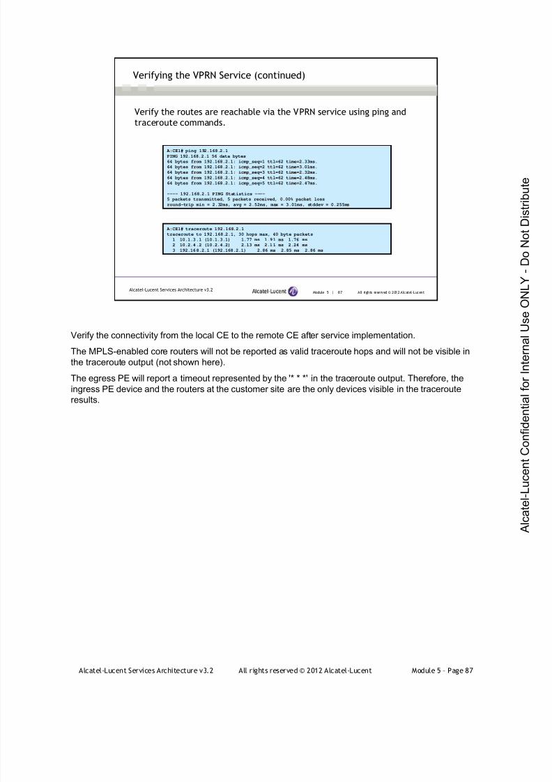
7/21/2019 Services Architecture v3.2 Student Guide Download
http://slidepdf.com/reader/full/services-architecture-v32-student-guide-download 363/429
Alcatel-Lucent Services Architecture v3.2 All rights reserved © 2012 Alcatel-Lucent Module 5 – Page 87
Module 5 | 87 All rights reserved © 2012 Alcatel-LucentAlcatel-Lucent Services Architecture v3.2
A:CE1# ping 192.168.2.1
PING 192.168.2.1 56 data bytes
64 bytes from 192.168.2.1: icmp_seq=1 ttl=62 time=2.33ms.
64 bytes from 192.168.2.1: icmp_seq=2 ttl=62 time=3.01ms.
64 bytes from 192.168.2.1: icmp_seq=3 ttl=62 time=2.32ms.
64 bytes from 192.168.2.1: icmp_seq=4 ttl=62 time=2.48ms.
64 bytes from 192.168.2.1: icmp_seq=5 ttl=62 time=2.47ms.
---- 192.168.2.1 PING Statistics ----
5 packets transmitted, 5 packets received, 0.00% packet loss
round-trip min = 2.32ms, avg = 2.52ms, max = 3.01ms, stddev = 0.255ms
Verifying the VPRN Service (continued)
A:CE1# traceroute 192.168.2.1
traceroute to 192.168.2.1, 30 hops max, 40 byte packets
1 10.1.3.1 (10.1.3.1) 1.77 ms 1.91 ms 1.76 ms
2 10.2.4.2 (10.2.4.2) 2.13 ms 2.11 ms 2.24 ms
3 192.168.2.1 (192.168.2.1) 2.86 ms 2.85 ms 2.86 ms
Verify the routes are reachable via the VPRN service using ping and
traceroute commands.
Verify the connectivity from the local CE to the remote CE after service implementation.
The MPLS-enabled core routers will not be reported as valid traceroute hops and will not be visible in
the traceroute output (not shown here).
The egress PE will report a timeout represented by the '* * *' in the traceroute output. Therefore, the
ingress PE device and the routers at the customer site are the only devices visible in the traceroute
results.

7/21/2019 Services Architecture v3.2 Student Guide Download
http://slidepdf.com/reader/full/services-architecture-v32-student-guide-download 364/429
Alcatel-Lucent Services Architecture v3.2 All rights reserved © 2012 Alcatel-Lucent Module 5 – Page 88
Module 5 | 88 All r ights reserved ©2012 Alcatel-LucentAlcatel-Lucent Services Architecture v3.2
Verifying the VPRN using OAM tools
A:PE1# oam vprn-trace 1 source 10.1.3.1 destination 10.2.4.2
TTL Seq Rcvd-on Repl y- Pat h RTT- - - - - - - - - - - - - - - - - - - - - - - - - - - - - - - - - - - - - - - - - - - - - - - - - - - - - - - - - - - - - - - - - - - - - - - - - - - -[ Send request TTL: 1, Seq. 1. ]1 1 cpm I n- Band 0. 826msNode-I d 10. 10. 10. 2
Requestor 10. 10.10. 1Route: 10.2.4.0/27
Vpn Label: 131069 Met r i cs 0 Pref 170 Owner bgpVpn Next Hops: [1] ldp tunnel
Route Targets: [1]: target:64496:10
Responder 10. 10.10. 2Route: 10. 2.4. 2/32Vpn Label : 0 Metri cs 0 Pref 0 Owner l ocalNext Hops: [1] i f I dx 2 nextHopI p 10. 2. 4. 2
A:PE1# oam vprn-trace 1 source 10.1.3.1 destination 10.2.4.2
TTL Seq Rcvd-on Repl y- Pat h RTT- - - - - - - - - - - - - - - - - - - - - - - - - - - - - - - - - - - - - - - - - - - - - - - - - - - - - - - - - - - - - - - - - - - - - - - - - - - -[ Send r equest TTL: 1, Seq. 1.]1 1 cpm I n- Band 0. 826msNode-I d 10. 10. 10. 2
Requestor 10. 10.10. 1Route: 10.2.4.0/27
Vpn Label: 131069 Met r i cs 0 Pref 170 Owner bgpVpn Next Hops: [1] ldp tunnel
Route Targets: [1]: target:64496:10
Responder 10. 10.10. 2Route: 10. 2.4. 2/32Vpn Label : 0 Metri cs 0 Pref 0 Owner l ocalNext Hops: [1] i f I dx 2 nextHopI p 10. 2. 4. 2
A:PE1# oam vprn-trace 2 source 10.1.6.1 destination 10.2.5.2
TTL Seq Rcvd-on Repl y- Pat h RTT- - - - - - - - - - - - - - - - - - - - - - - - - - - - - - - - - - - - - - - - - - - - - - - - - - - - - - - - - - - - - - - - - - - - - - - - - - - -[ Send request TTL: 1, Seq. 1. ]1 1 cpm I n- Band 0. 915msNode-I d 10. 10. 10. 2
Requestor 10. 10. 10. 1Route: 10.2.5.0/27
Vpn Label: 131068 Met r i cs 0 Pref 170 Owner bgpVpn Next Hops: [1] ldp tunnel
Route Targets: [1]: target:64496:20
Responder 10. 10. 10. 2Route: 10. 2.5. 2/32Vpn Label : 0 Metri cs 0 Pref 0 Owner l ocal
Next Hops: [1] i f I dx 2 nextHopI p 10. 2. 5. 2
A:PE1# oam vprn-trace 2 source 10.1.6.1 destination 10.2.5.2
TTL Seq Rcvd-on Repl y- Pat h RTT- - - - - - - - - - - - - - - - - - - - - - - - - - - - - - - - - - - - - - - - - - - - - - - - - - - - - - - - - - - - - - - - - - - - - - - - - - - -[ Send r equest TTL: 1, Seq. 1.]1 1 cpm I n- Band 0. 915msNode-I d 10. 10. 10. 2
Requestor 10. 10.10. 1Route: 10.2.5.0/27
Vpn Label: 131068 Met r i cs 0 Pref 170 Owner bgpVpn Next Hops: [1] ldp tunnel
Route Targets: [1]: target:64496:20
Responder 10. 10.10. 2Route: 10. 2.5. 2/32Vpn Label : 0 Metri cs 0 Pref 0 Owner l ocalNext Hops: [1] i f I dx 2 nextHopI p 10. 2. 5. 2
In order to verify that a service is operational, a set of in-band, packet-based operation, administration,
and maintenance (OAM) tools is required with the ability to test each of the individual packet
operations.
For in-band testing, the OAM packets closely resemble customer packets to effectively test the
customer's forwarding path, but they are distinguishable from customer packets so they are kept
within the service provider's network and not forwarded to the customer.
The suite of OAM diagnostics supplements the basic IP ping and traceroute operations withdiagnostics specialized for the different levels in the service delivery model.
The oam vprn-ping command is used to verify that the customer VPRN service is operational. The
oam vprn-trace command is used to verify the path taken for the customer VPRN service and the
tunneling mechanism used across the provider core.
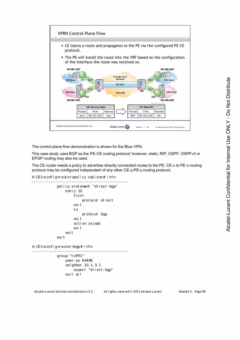
7/21/2019 Services Architecture v3.2 Student Guide Download
http://slidepdf.com/reader/full/services-architecture-v32-student-guide-download 365/429
Alcatel-Lucent Services Architecture v3.2 All rights reserved © 2012 Alcatel-Lucent Module 5 – Page 89
Module 5 | 89 All r ights reserved ©2012 Alcatel-LucentAlcatel-Lucent Services Architecture v3.2
VPRN Control Plane Flow
CE learns a route and propagates to the PE via the configured PE-CE
protocol.
The PE will install the route into the VRF based on the configuration
of the interface the route was received on.
The control plane flow demonstration is shown for the Blue VPN.
This case study uses BGP as the PE-CE routing protocol; however, static, RIP, OSPF, OSPFv3 or
EPGP routing may also be used.
The CE router needs a policy to advertise directly connected routes to the PE. CE-x to PE-x routing
protocol may be configured independent of any other CE-y-PE-y routing protocol.
A: CE1>conf i g>r out er>pol i cy- opt i ons# i nf o- - - - - - - - - - - - - - - - - - - - - - - - - - - - - - - - - - - - - - - - - - - - - -
pol i cy- st at ement "di r ect - bgp"
ent r y 10
f rom
prot ocol di rect
exi t
t o
pr otocol bgp
exi t
act i on accept
exi t
exi t
exi t
A: CE1>conf i g>r outer>bgp# i nf o
- - - - - - - - - - - - - - - - - - - - - - - - - - - - - - - - - - - - - - - - - - - - - -
group "t oPE1"
peer - as 64496
nei ghbor 10. 1. 3. 1
expor t "di r ect - bgp"
exi t al l
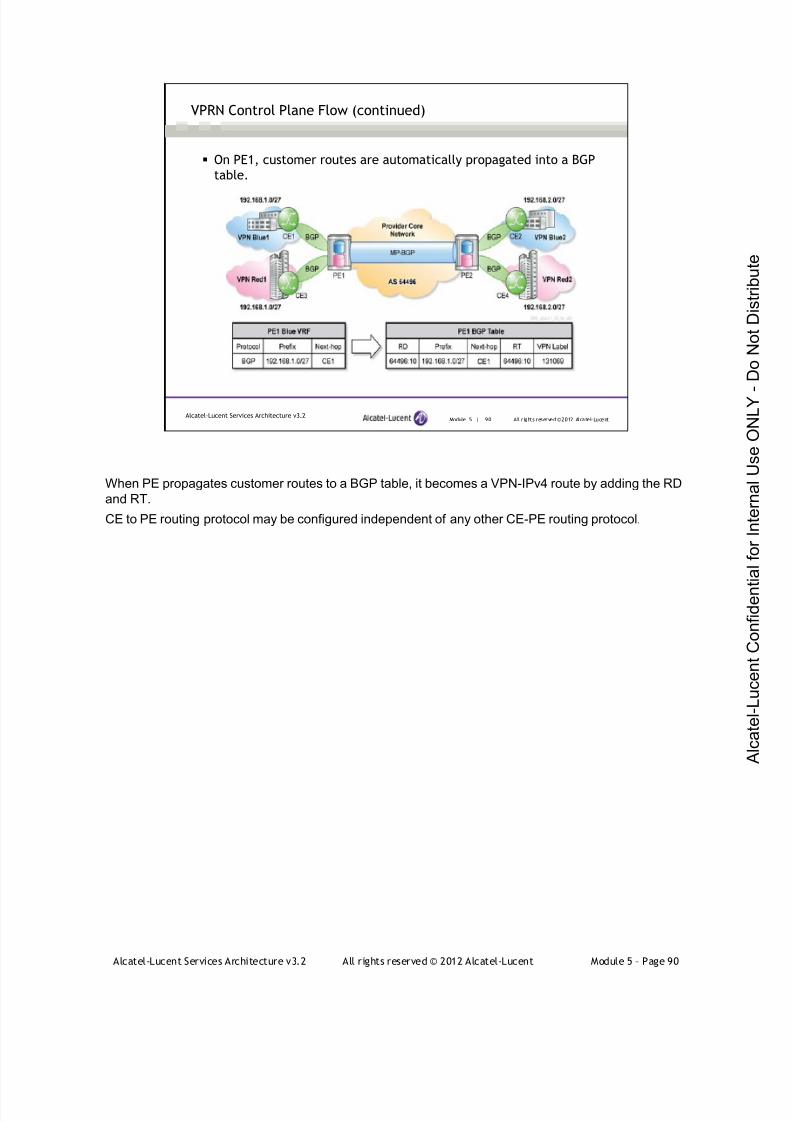
7/21/2019 Services Architecture v3.2 Student Guide Download
http://slidepdf.com/reader/full/services-architecture-v32-student-guide-download 366/429
Alcatel-Lucent Services Architecture v3.2 All rights reserved © 2012 Alcatel-Lucent Module 5 – Page 90
Module 5 | 90 All r ights reserved ©2012 Alcatel-LucentAlcatel-Lucent Services Architecture v3.2
VPRN Control Plane Flow (continued)
On PE1, customer routes are automatically propagated into a BGP
table.
When PE propagates customer routes to a BGP table, it becomes a VPN-IPv4 route by adding the RD
and RT.
CE to PE routing protocol may be configured independent of any other CE-PE routing protocol.
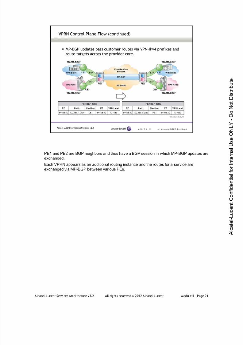
7/21/2019 Services Architecture v3.2 Student Guide Download
http://slidepdf.com/reader/full/services-architecture-v32-student-guide-download 367/429
Alcatel-Lucent Services Architecture v3.2 All rights reserved © 2012 Alcatel-Lucent Module 5 – Page 91
Module 5 | 91 All r ights reserved ©2012 Alcatel-LucentAlcatel-Lucent Services Architecture v3.2
VPRN Control Plane Flow (continued)
MP-BGP updates pass customer routes via VPN-IPv4 prefixes and
route targets across the provider core.
PE1 and PE2 are BGP neighbors and thus have a BGP session in which MP-BGP updates are
exchanged.
Each VPRN appears as an additional routing instance and the routes for a service are
exchanged via MP-BGP between various PEs.

7/21/2019 Services Architecture v3.2 Student Guide Download
http://slidepdf.com/reader/full/services-architecture-v32-student-guide-download 368/429
Alcatel-Lucent Services Architecture v3.2 All rights reserved © 2012 Alcatel-Lucent Module 5 – Page 92
Module 5 | 92 All r ights reserved ©2012 Alcatel-LucentAlcatel-Lucent Services Architecture v3.2
VPRN Control Plane Flow (continued)
The receiving PE (egress PE) installs the VPN-IPv4 routes into a VRF
based on the route target in the MP-BGP update.
VPN LabelPrefix
131069192.168.1.0/27
PE2 FIB
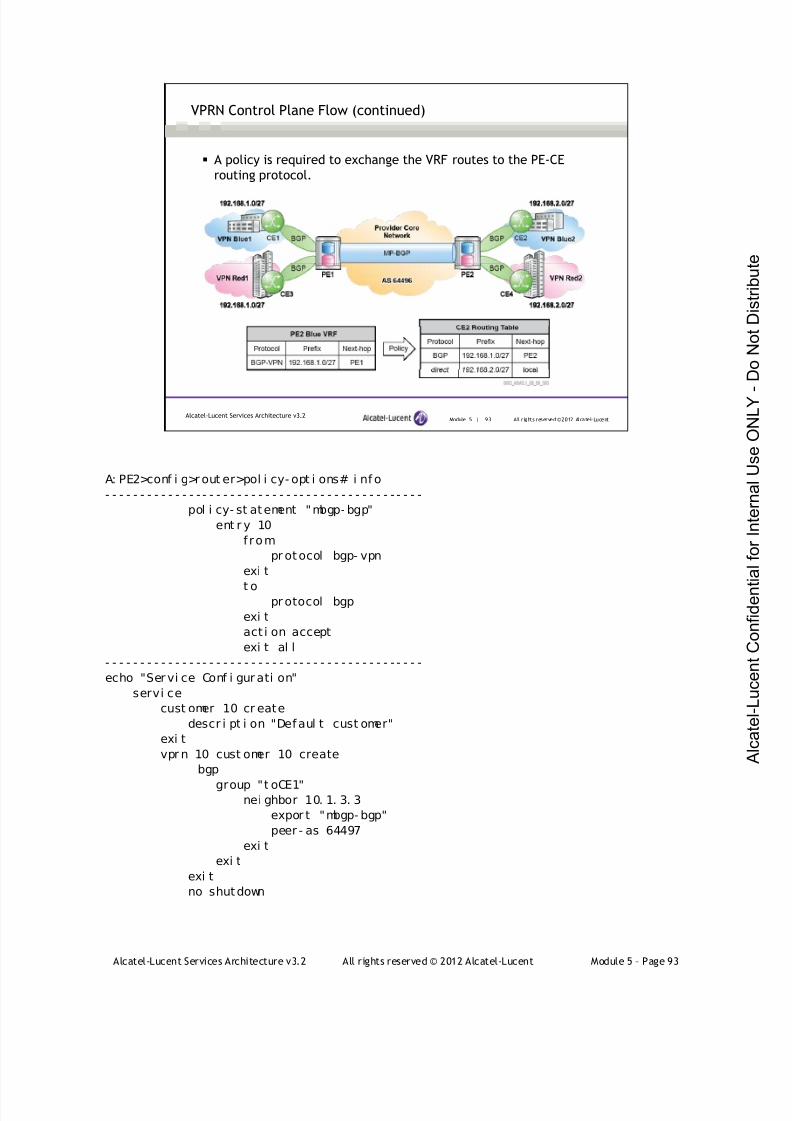
7/21/2019 Services Architecture v3.2 Student Guide Download
http://slidepdf.com/reader/full/services-architecture-v32-student-guide-download 369/429
Alcatel-Lucent Services Architecture v3.2 All rights reserved © 2012 Alcatel-Lucent Module 5 – Page 93
Module 5 | 93 All r ights reserved ©2012 Alcatel-LucentAlcatel-Lucent Services Architecture v3.2
VPRN Control Plane Flow (continued)
A policy is required to exchange the VRF routes to the PE-CE
routing protocol.
A: PE2>conf i g>r out er>pol i cy- opt i ons# i nf o
- - - - - - - - - - - - - - - - - - - - - - - - - - - - - - - - - - - - - - - - - - - - - -
pol i cy- st atement "mbgp- bgp"
ent r y 10
f rom
pr otocol bgp- vpn
exi t
t opr otocol bgp
exi t
act i on accept
exi t al l
- - - - - - - - - - - - - - - - - - - - - - - - - - - - - - - - - - - - - - - - - - - - - -
echo "Ser vi ce Conf i gur ati on"
servi ce
cust omer 10 cr eate
descr i pt i on "Defaul t cust omer"
exi t
vpr n 10 cust omer 10 create
bgp
group "t oCE1"nei ghbor 10. 1. 3. 3
expor t "mbgp- bgp"
peer - as 64497
exi t
exi t
exi t
no shutdown

7/21/2019 Services Architecture v3.2 Student Guide Download
http://slidepdf.com/reader/full/services-architecture-v32-student-guide-download 370/429
Alcatel-Lucent Services Architecture v3.2 All rights reserved © 2012 Alcatel-Lucent Module 5 – Page 94
Module 5 | 94 All r ights reserved ©2012 Alcatel-LucentAlcatel-Lucent Services Architecture v3.2
VPRN Control Plane Flow (continued)
Return Path
A bi-directional route exchange must occur across the core
Similarly, route exchanges must occur in the opposite direction. CE2 learns a route and propagates to
PE2 via the configured PE-CE protocol (BGP). PE2 will then install the route into the VRF based on
the configuration of the interface the route is received on. Customer routes are then automatically
propagated into the BGP table on the PE2.
MP-BGP updates pass the customer routes via VPN-IPv4 prefixes and route targets across the
provider core. The receiving PE (PE1) places all VPN-IPv4 routes into the VRFs corresponding to the
proper route targets. The VRF routes are then exchanged to the PE1-CE1 routing protocol via policy.
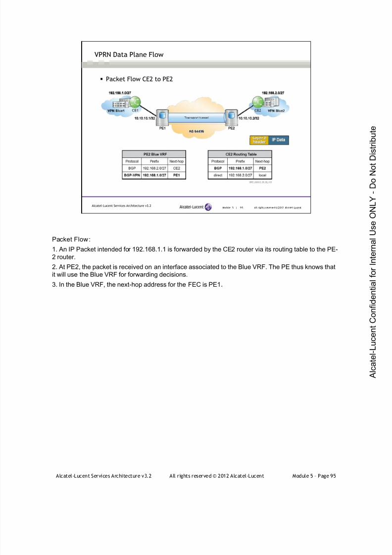
7/21/2019 Services Architecture v3.2 Student Guide Download
http://slidepdf.com/reader/full/services-architecture-v32-student-guide-download 371/429
Alcatel-Lucent Services Architecture v3.2 All rights reserved © 2012 Alcatel-Lucent Module 5 – Page 95
Module 5 | 95 All r ights reserved ©2012 Alcatel-LucentAlcatel-Lucent Services Architecture v3.2
VPRN Data Plane Flow
Packet Flow CE2 to PE2
Packet Flow:
1. An IP Packet intended for 192.168.1.1 is forwarded by the CE2 router via its routing table to the PE-
2 router.
2. At PE2, the packet is received on an interface associated to the Blue VRF. The PE thus knows that
it will use the Blue VRF for forwarding decisions.
3. In the Blue VRF, the next-hop address for the FEC is PE1.
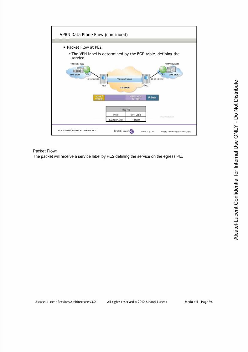
7/21/2019 Services Architecture v3.2 Student Guide Download
http://slidepdf.com/reader/full/services-architecture-v32-student-guide-download 372/429
Alcatel-Lucent Services Architecture v3.2 All rights reserved © 2012 Alcatel-Lucent Module 5 – Page 96
Module 5 | 96 All r ights reserved ©2012 Alcatel-LucentAlcatel-Lucent Services Architecture v3.2
VPRN Data Plane Flow (continued)
Packet Flow at PE2
The VPN label is determined by the BGP table, defining theservice
VPN LabelPrefix
131069192.168.1.0/27
PE2 FIB
Packet Flow:
The packet will receive a service label by PE2 defining the service on the egress PE.

7/21/2019 Services Architecture v3.2 Student Guide Download
http://slidepdf.com/reader/full/services-architecture-v32-student-guide-download 373/429
Alcatel-Lucent Services Architecture v3.2 All rights reserved © 2012 Alcatel-Lucent Module 5 – Page 97
Module 5 | 97 All r ights reserved ©2012 Alcatel-LucentAlcatel-Lucent Services Architecture v3.2
VPRN Data Plane Flow (continued)
Packet Flow at PE2
The transport label is determined by the LFIB for the next-hop,defining the transport tunnel
Packet Flow:
1. A label will be determined for the next-hop address from the LFIB. The label associated to
10.10.10.1 is 131071.
2. The packet will be labeled by PE2 with a transport label of 131071, which defines the transport
tunnel to the egress PE.
Note: Packet flow at P routers (not shown in the slide): each P router along the path will swap the LSP
label and label switches the packet towards the egress PE. There are no changes to the IP header orthe VPN label in the core network. The packet will be label switched across the provider core until it
reaches the egress PE.
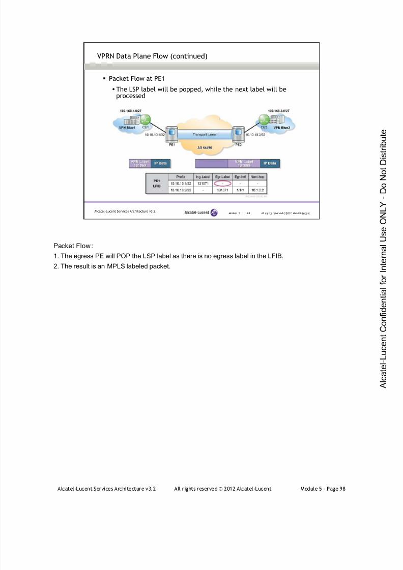
7/21/2019 Services Architecture v3.2 Student Guide Download
http://slidepdf.com/reader/full/services-architecture-v32-student-guide-download 374/429
Alcatel-Lucent Services Architecture v3.2 All rights reserved © 2012 Alcatel-Lucent Module 5 – Page 98
Module 5 | 98 All r ights reserved ©2012 Alcatel-LucentAlcatel-Lucent Services Architecture v3.2
VPRN Data Plane Flow (continued)
Packet Flow at PE1
The LSP label will be popped, while the next label will beprocessed
Packet Flow:
1. The egress PE will POP the LSP label as there is no egress label in the LFIB.
2. The result is an MPLS labeled packet.

7/21/2019 Services Architecture v3.2 Student Guide Download
http://slidepdf.com/reader/full/services-architecture-v32-student-guide-download 375/429
Alcatel-Lucent Services Architecture v3.2 All rights reserved © 2012 Alcatel-Lucent Module 5 – Page 99
Module 5 | 99 All r ights reserved ©2012 Alcatel-LucentAlcatel-Lucent Services Architecture v3.2
VPRN Data Plane Flow (continued)
Packet Flow at PE1
The VPN label will be popped, while the unlabeled packet will be sentout to the interface corresponding to the longest match lookup
algorithm
VPN LabelPrefix
131069192.168.1.0/27
PE1 FIB
Packet Flow:
1. The egress PE will reference the VPN label and determine the associated VRF as there is a unique
one-to-one association between a VPN label and a VRF.
2. The VPN label is popped and results in an unlabeled packet forwarded via the VRF based on the
longest match lookup algorithm.
3. The next-hop is identified as being external to the MPLS domain. The packet will be forwarded by
PE1 to CE1.
4. CE1 receives an unlabeled packet for destination 192.168.1.1 and will route the unlabeled packet
via its routing table.
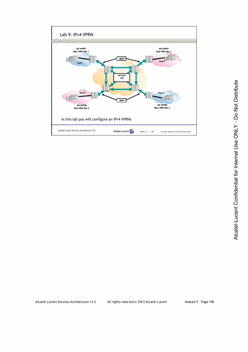
7/21/2019 Services Architecture v3.2 Student Guide Download
http://slidepdf.com/reader/full/services-architecture-v32-student-guide-download 376/429
Alcatel-Lucent Services Architecture v3.2 All rights reserved © 2012 Alcatel-Lucent Module 5 – Page 100
Module 5 | 100 All rights reserved ©2012 Alcatel-LucentAlcatel-Lucent Services Architecture v3.2
Lab 9: IPv4 VPRN
In this lab you will configure an IPv4 VPRNs
AS 64497
Blue VPN Site 1
AS 64500
Red VPN Site 2
AS 64499
Red VPN Site 1
AS 64498
Blue VPN Site 2
BGP
BGP
MP-BGP
LDP
Pod 1 Pod 2
Pod 3 Pod 4

7/21/2019 Services Architecture v3.2 Student Guide Download
http://slidepdf.com/reader/full/services-architecture-v32-student-guide-download 377/429
Alcatel-Lucent Services Architecture v3.2 All rights reserved © 2012 Alcatel-Lucent Module 5 – Page 101
Module 5 — Layer 3 VPNs
Section 6 — IPv6 VPRN

7/21/2019 Services Architecture v3.2 Student Guide Download
http://slidepdf.com/reader/full/services-architecture-v32-student-guide-download 378/429
Alcatel-Lucent Services Architecture v3.2 All rights reserved © 2012 Alcatel-Lucent Module 5 – Page 102
Module 5 | 102 All rights reserved ©2012 Alcatel-LucentAlcatel-Lucent Services Architecture v3.2
Section Objectives
After successfully completing this section, you will be able to:
Describe the operation of 6VPE
Configure and verify a basic 6VPE
Complete Lab 10 – Configure and verify an IPv6 VPRN using
BGP as the PE-CE routing protocol and LDP for signaling in the
IPv4 core
7/21/2019 Services Architecture v3.2 Student Guide Download
http://slidepdf.com/reader/full/services-architecture-v32-student-guide-download 379/429
Alcatel-Lucent Services Architecture v3.2 All rights reserved © 2012 Alcatel-Lucent Module 5 – Page 103
Module 5 | 103 All rights reserved ©2012 Alcatel-LucentAlcatel-Lucent Services Architecture v3.2
Transition from IPv4 to IPv6
Internet Protocol version 6 (IPv6) is a replacement of IPv4
IPv6 is deployed in phases
Currently, the main body of the Internet is still using IPv4, whereas
IPv6 is only deployed in a few IPv6 backbone networks
How can we enable those isolated IPv6 networks to communicate
with each other?
Tunneling technologies are used to connect separated IPv6
networks
Internet Protocol version 6 (IPv6) is a replacement of IPv4. The industry believes that IPv6 will
boost the development of a series of new services and technologies, particularly in mobile
communications and digital home appliances.
IPv6 cannot be deployed in one action. IPv4 is currently a dominant protocol of the Internet in which
almost all applications on the IP network are based on it. Thus, the applications of IPv6 are to be
developed step-by-step.
Currently, the main body of the Internet is still using IPv4, whereas IPv6 is deployed in merely a fewIPv6 backbone networks such as the CNGI in China and the e-Japan in Japan. The primary issue is
how to enable those isolated IPv6 networks to communicate with each other.
There are many issues involved when interconnecting IPv4 and IPv6 networks, as well as many
strategies for transitioning to IPv6. Tunneling technologies are used to connect separated IPv6
networks.
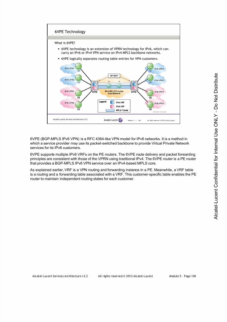
7/21/2019 Services Architecture v3.2 Student Guide Download
http://slidepdf.com/reader/full/services-architecture-v32-student-guide-download 380/429
Alcatel-Lucent Services Architecture v3.2 All rights reserved © 2012 Alcatel-Lucent Module 5 – Page 104
Module 5 | 104 All rights reserved ©2012 Alcatel-LucentAlcatel-Lucent Services Architecture v3.2
6VPE Technology
What is 6VPE?
6VPE technology is an extension of VPRN technology for IPv6, which cancarry an IPv6 or IPv4 VPN service on IPv4 MPLS backbone networks.
6VPE logically separates routing table entries for VPN customers.
6VPE (BGP-MPLS IPv6 VPN) is a RFC 4364-like VPN model for IPv6 networks. It is a method in
which a service provider may use its packet-switched backbone to provide Virtual Private Network
services for its IPv6 customers.
6VPE supports multiple IPv6 VRFs on the PE routers. The 6VPE route delivery and packet forwarding
principles are consistent with those of the VPRN using traditional IPv4. The 6VPE router is a PE router
that provides a BGP-MPLS IPv6 VPN service over an IPv4-based MPLS core.
As explained earlier, VRF is a VPN routing and forwarding instance in a PE. Meanwhile, a VRF tableis a routing and a forwarding table associated with a VRF. This customer-specific table enables the PE
router to maintain independent routing states for each customer.
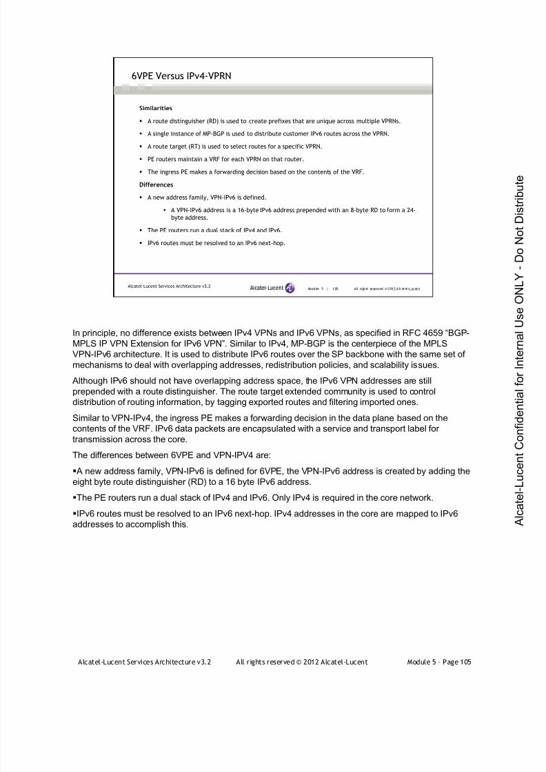
7/21/2019 Services Architecture v3.2 Student Guide Download
http://slidepdf.com/reader/full/services-architecture-v32-student-guide-download 381/429
Alcatel-Lucent Services Architecture v3.2 All rights reserved © 2012 Alcatel-Lucent Module 5 – Page 105
Module 5 | 105 All rights reserved ©2012 Alcatel-LucentAlcatel-Lucent Services Architecture v3.2
6VPE Versus IPv4-VPRN
Similarities
A route distinguisher (RD) is used to create prefixes that are unique across multiple VPRNs.
A single instance of MP-BGP is used to distribute customer IPv6 routes across the VPRN.
A route target (RT) is used to select routes for a specific VPRN.
PE routers maintain a VRF for each VPRN on that router.
The ingress PE makes a forwarding decision based on the contents of the VRF.
Differences
A new address family, VPN-IPv6 is defined.
A VPN-IPv6 address is a 16-byte IPv6 address prepended with an 8-byte RD to form a 24-
byte address.
The PE routers run a dual stack of IPv4 and IPv6.
IPv6 routes must be resolved to an IPv6 next-hop.
In principle, no difference exists between IPv4 VPNs and IPv6 VPNs, as specified in RFC 4659 “BGP-
MPLS IP VPN Extension for IPv6 VPN”. Similar to IPv4, MP-BGP is the centerpiece of the MPLS
VPN-IPv6 architecture. It is used to distribute IPv6 routes over the SP backbone with the same set of
mechanisms to deal with overlapping addresses, redistribution policies, and scalability issues.
Although IPv6 should not have overlapping address space, the IPv6 VPN addresses are still
prepended with a route distinguisher. The route target extended community is used to control
distribution of routing information, by tagging exported routes and filtering imported ones.Similar to VPN-IPv4, the ingress PE makes a forwarding decision in the data plane based on the
contents of the VRF. IPv6 data packets are encapsulated with a service and transport label for
transmission across the core.
The differences between 6VPE and VPN-IPV4 are:
A new address family, VPN-IPv6 is defined for 6VPE, the VPN-IPv6 address is created by adding the
eight byte route distinguisher (RD) to a 16 byte IPv6 address.
The PE routers run a dual stack of IPv4 and IPv6. Only IPv4 is required in the core network.
IPv6 routes must be resolved to an IPv6 next-hop. IPv4 addresses in the core are mapped to IPv6
addresses to accomplish this.
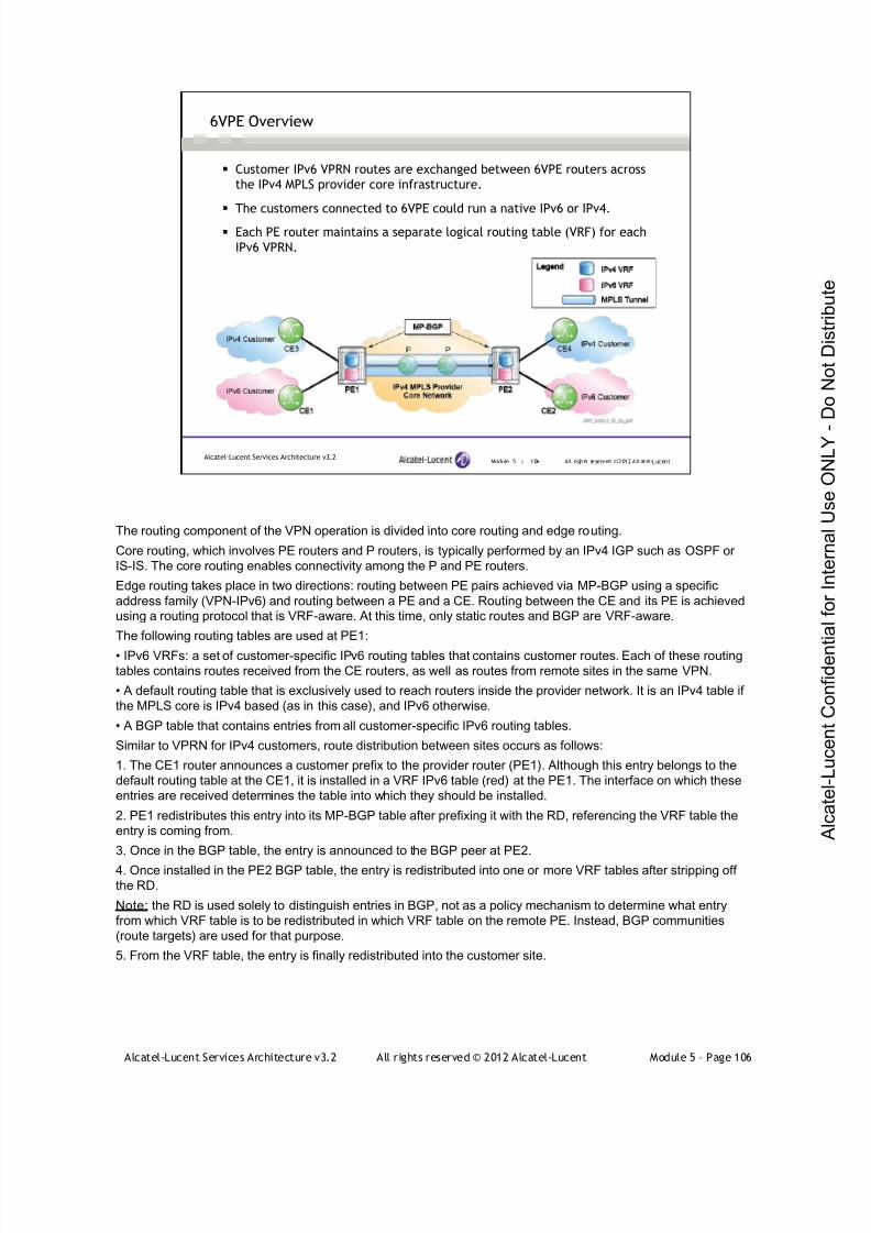
7/21/2019 Services Architecture v3.2 Student Guide Download
http://slidepdf.com/reader/full/services-architecture-v32-student-guide-download 382/429
Alcatel-Lucent Services Architecture v3.2 All rights reserved © 2012 Alcatel-Lucent Module 5 – Page 106
Module 5 | 106 All rights reserved ©2012 Alcatel-LucentAlcatel-Lucent Services Architecture v3.2
6VPE Overview
Customer IPv6 VPRN routes are exchanged between 6VPE routers across
the IPv4 MPLS provider core infrastructure.
The customers connected to 6VPE could run a native IPv6 or IPv4.
Each PE router maintains a separate logical routing table (VRF) for each
IPv6 VPRN.
The routing component of the VPN operation is divided into core routing and edge routing.
Core routing, which involves PE routers and P routers, is typically performed by an IPv4 IGP such as OSPF or
IS-IS. The core routing enables connectivity among the P and PE routers.
Edge routing takes place in two directions: routing between PE pairs achieved via MP-BGP using a specific
address family (VPN-IPv6) and routing between a PE and a CE. Routing between the CE and its PE is achievedusing a routing protocol that is VRF-aware. At this time, only static routes and BGP are VRF-aware.
The following routing tables are used at PE1:
• IPv6 VRFs: a set of customer-specific IPv6 routing tables that contains customer routes. Each of these routing
tables contains routes received from the CE routers, as well as routes from remote sites in the same VPN.
• A default routing table that is exclusively used to reach routers inside the provider network. It is an IPv4 table if
the MPLS core is IPv4 based (as in this case), and IPv6 otherwise.
• A BGP table that contains entries from all customer-specific IPv6 routing tables.
Similar to VPRN for IPv4 customers, route distribution between sites occurs as follows:
1. The CE1 router announces a customer prefix to the provider router (PE1). Although this entry belongs to the
default routing table at the CE1, it is installed in a VRF IPv6 table (red) at the PE1. The interface on which these
entries are received determines the table into which they should be installed.
2. PE1 redistributes this entry into its MP-BGP table after prefixing it with the RD, referencing the VRF table the
entry is coming from.
3. Once in the BGP table, the entry is announced to the BGP peer at PE2.
4. Once installed in the PE2 BGP table, the entry is redistributed into one or more VRF tables after stripping off
the RD.
Note: the RD is used solely to distinguish entries in BGP, not as a policy mechanism to determine what entry
from which VRF table is to be redistributed in which VRF table on the remote PE. Instead, BGP communities
(route targets) are used for that purpose.
5. From the VRF table, the entry is finally redistributed into the customer site.

7/21/2019 Services Architecture v3.2 Student Guide Download
http://slidepdf.com/reader/full/services-architecture-v32-student-guide-download 383/429
Alcatel-Lucent Services Architecture v3.2 All rights reserved © 2012 Alcatel-Lucent Module 5 – Page 107
Module 5 | 107 All rights reserved ©2012 Alcatel-LucentAlcatel-Lucent Services Architecture v3.2
6VPE Label Stack
The IPv6 VPRN Service, similar to IPv4 VPRNs, uses a label stack consisting
of two labels.
The outer label is known as the top, transport, or LSP label that identifies
the transport tunnel between PE’s.
Signaled via LDP or RSVP
The inner label is known as the service, VC, or VPN label that identifies
the customer VPRN.
Signaled via MP-BGP
These labels are applied on the IPv6 packet directly (no additional headers
are needed although the core is IPv4)
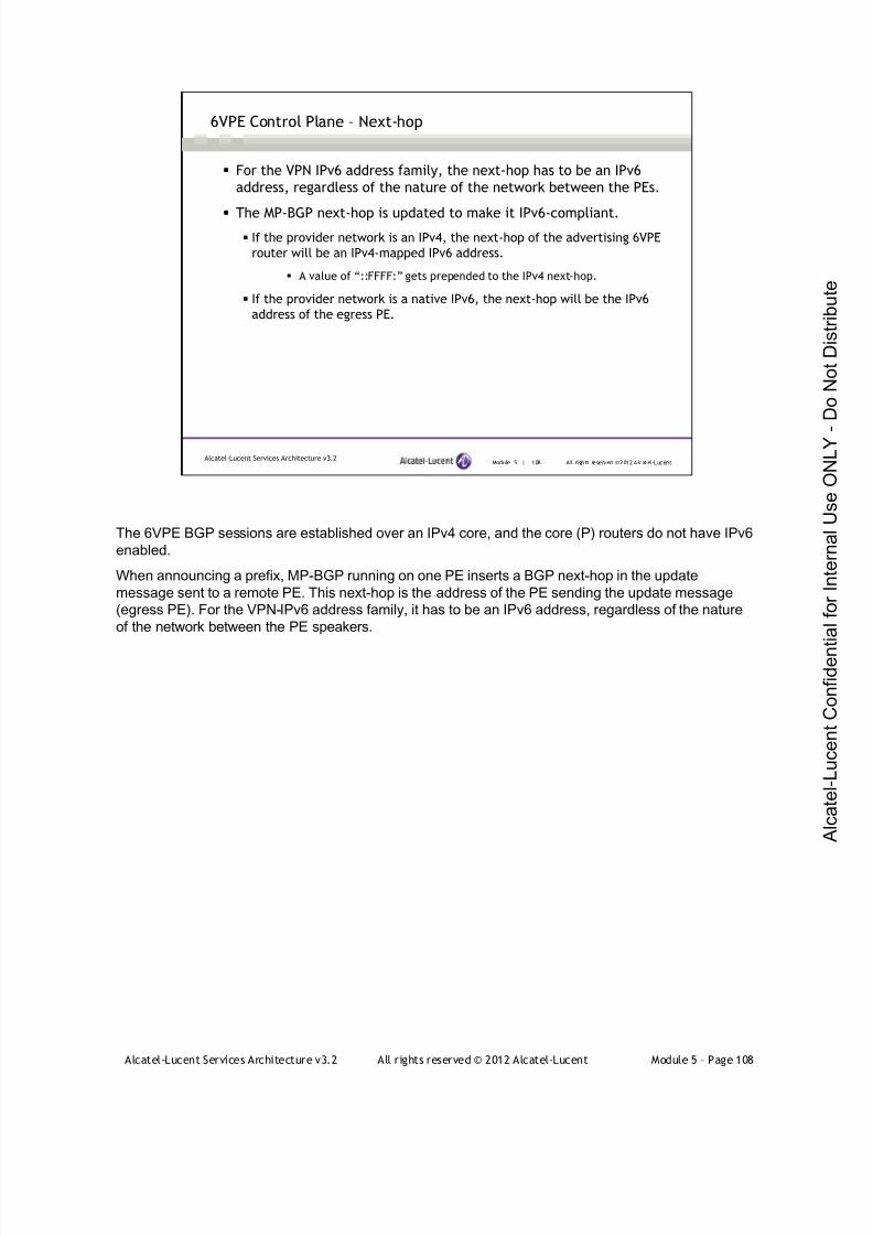
7/21/2019 Services Architecture v3.2 Student Guide Download
http://slidepdf.com/reader/full/services-architecture-v32-student-guide-download 384/429
Alcatel-Lucent Services Architecture v3.2 All rights reserved © 2012 Alcatel-Lucent Module 5 – Page 108
Module 5 | 108 All rights reserved ©2012 Alcatel-LucentAlcatel-Lucent Services Architecture v3.2
6VPE Control Plane – Next-hop
For the VPN IPv6 address family, the next-hop has to be an IPv6
address, regardless of the nature of the network between the PEs.
The MP-BGP next-hop is updated to make it IPv6-compliant. If the provider network is an IPv4, the next-hop of the advertising 6VPE
router will be an IPv4-mapped IPv6 address.
A value of “::FFFF:” gets prepended to the IPv4 next-hop.
If the provider network is a native IPv6, the next-hop will be the IPv6
address of the egress PE.
The 6VPE BGP sessions are established over an IPv4 core, and the core (P) routers do not have IPv6
enabled.
When announcing a prefix, MP-BGP running on one PE inserts a BGP next-hop in the update
message sent to a remote PE. This next-hop is the address of the PE sending the update message
(egress PE). For the VPN-IPv6 address family, it has to be an IPv6 address, regardless of the nature
of the network between the PE speakers.

7/21/2019 Services Architecture v3.2 Student Guide Download
http://slidepdf.com/reader/full/services-architecture-v32-student-guide-download 385/429
Alcatel-Lucent Services Architecture v3.2 All rights reserved © 2012 Alcatel-Lucent Module 5 – Page 109
Module 5 | 109 All rights reserved ©2012 Alcatel-LucentAlcatel-Lucent Services Architecture v3.2
6VPE Data Plane – Ingress 6VPE Router
When the ingress 6VPE router receives an IPv6 packet, it looks for the destination
address in the VRF table.
This destination prefix is either local to the 6VPE (which is another interface participating inthe VPN) or a remote ingress 6VPE router.
For the prefix learned through the remote 6VPE router, the ingress router does a
lookup in the VPN-IPv6 forwarding table.
The VPN-IPv6 route has an associated MPLS label to a MBGP next-hop and an
associated VPRN service label.
The ingress 6VPE router needs to push two MPLS labels in order to send the packets
to the egress 6VPE router.
The top label is an MPLS IPv4 label that is used to reach the egress 6VPE router.
The bottom label is an MPLS label that is advertised in MBGP by the remote 6VPE router for
the IPv6 prefixes in the VRF.
7/21/2019 Services Architecture v3.2 Student Guide Download
http://slidepdf.com/reader/full/services-architecture-v32-student-guide-download 386/429
Alcatel-Lucent Services Architecture v3.2 All rights reserved © 2012 Alcatel-Lucent Module 5 – Page 110
Module 5 | 110 All rights reserved ©2012 Alcatel-LucentAlcatel-Lucent Services Architecture v3.2
6VPE Data Plane – Egress 6VPE Router
The provider core (P) routers label switch the packets to the correct
egress 6VPE via the transport label.
The egress 6VPE router receives label-stacked packets from the core.
The egress 6VPE router pops the top transport label.
The egress 6VPE router pops the bottom IPv6 VPRN service label and
identifies the target VRF and the address family.
A further Layer 3 lookup is performed in the target VRF and the IPv6
packet is sent toward the proper customer edge router in the IPv6 domain.
The egress 6VPE forwards unlabeled packets to the customer
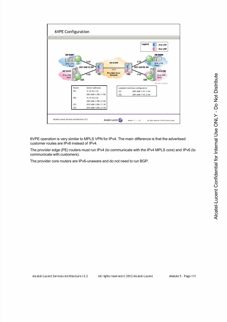
7/21/2019 Services Architecture v3.2 Student Guide Download
http://slidepdf.com/reader/full/services-architecture-v32-student-guide-download 387/429
Alcatel-Lucent Services Architecture v3.2 All rights reserved © 2012 Alcatel-Lucent Module 5 – Page 111
Module 5 | 111 All rights reserved ©2012 Alcatel-LucentAlcatel-Lucent Services Architecture v3.2
6VPE Configuration
Router System addresses
PE1 10.10.10.1/32
2001:db8:1:100::1/128
PE2 10.10.10.2/32
2001:db8:1:100::2/128
CE1 2001:db8:1:200::1/128
CE2 2001:db8:1:200::2/128
Loopback interfaces configured on
CE1 2001:db8:1:1f1::1/64
CE2 2001:db8:1:1f2::2/64
6VPE operation is very similar to MPLS VPN for IPv4. The main difference is that the advertised
customer routes are IPv6 instead of IPv4.
The provider edge (PE) routers must run IPv4 (to communicate with the IPv4 MPLS core) and IPv6 (to
communicate with customers).
The provider core routers are IPv6-unaware and do not need to run BGP.
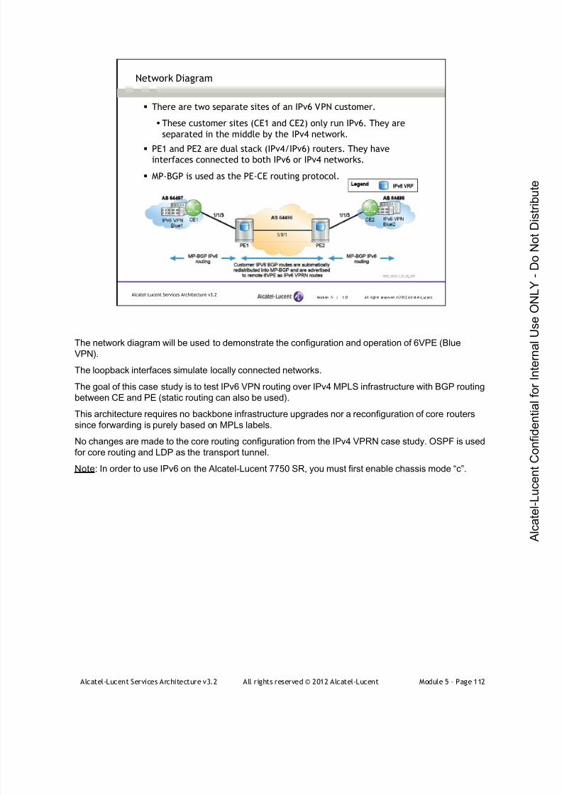
7/21/2019 Services Architecture v3.2 Student Guide Download
http://slidepdf.com/reader/full/services-architecture-v32-student-guide-download 388/429
Alcatel-Lucent Services Architecture v3.2 All rights reserved © 2012 Alcatel-Lucent Module 5 – Page 112
Module 5 | 112 All rights reserved ©2012 Alcatel-LucentAlcatel-Lucent Services Architecture v3.2
Network Diagram
There are two separate sites of an IPv6 VPN customer.
These customer sites (CE1 and CE2) only run IPv6. They are
separated in the middle by the IPv4 network.
PE1 and PE2 are dual stack (IPv4/IPv6) routers. They have
interfaces connected to both IPv6 or IPv4 networks.
MP-BGP is used as the PE-CE routing protocol.
The network diagram will be used to demonstrate the configuration and operation of 6VPE (Blue
VPN).
The loopback interfaces simulate locally connected networks.
The goal of this case study is to test IPv6 VPN routing over IPv4 MPLS infrastructure with BGP routing
between CE and PE (static routing can also be used).
This architecture requires no backbone infrastructure upgrades nor a reconfiguration of core routerssince forwarding is purely based on MPLs labels.
No changes are made to the core routing configuration from the IPv4 VPRN case study. OSPF is used
for core routing and LDP as the transport tunnel.
Note: In order to use IPv6 on the Alcatel-Lucent 7750 SR, you must first enable chassis mode “c”.

7/21/2019 Services Architecture v3.2 Student Guide Download
http://slidepdf.com/reader/full/services-architecture-v32-student-guide-download 389/429
Alcatel-Lucent Services Architecture v3.2 All rights reserved © 2012 Alcatel-Lucent Module 5 – Page 113
Module 5 | 113 All rights reserved ©2012 Alcatel-LucentAlcatel-Lucent Services Architecture v3.2
PE-CE BGP IPv6 Routing Configuration
CE1 BGP Configuration (Similar to CE2).
#- - - - - - - - - - - - - - - - - - - - - - - - - - - - - - - - - - - - - - - - - - - - - - - - - -echo "BGP Conf i gur ati on"#- - - - - - - - - - - - - - - - - - - - - - - - - - - - - - - - - - - - - - - - - - - - - - - - - -
bgpl ocal - as 64497group "t oPE1"
f ami l y i pv6neighbor 2001: db8:12:: 2
export "di rect- bgp"peer - as 64496
exi texi t
exi texi t
#- - - - - - - - - - - - - - - - - - - - - - - - - - - - - - - - - - - - - - - - - - - - - - - - - -echo "BGP Conf i gurat i on"#- - - - - - - - - - - - - - - - - - - - - - - - - - - - - - - - - - - - - - - - - - - - - - - - - -
bgpl ocal - as 64497group "t oPE1"
f ami l y i pv6nei ghbor 2001: db8:12:: 2
export "di rect- bgp"peer - as 64496
exi texi t
exi texi t
BGP is used as a PE-CE protocol. The BGP configuration is pretty straightforward with an “ipv6”
family and the use of an IPv6 address for neighbor declaration. No changes are needed for the policy
configuration, which are used to redistribute customer routes into BGP.
#- - - - - - - - - - - - - - - - - - - - - - - - - - - - - - - - - - - - - - - - - - - - - - - - - -
echo "Pol i cy Conf i gur at i on"
#- - - - - - - - - - - - - - - - - - - - - - - - - - - - - - - - - - - - - - - - - - - - - - - - - -
pol i cy- opt i ons
begi n
pol i cy- st at ement "di r ect - bgp"
ent r y 10
f rom
prot ocol di rect
exi t
t o
pr otocol bgp
exi t
act i on accept
exi t
exi t
exi t
commi t
exi t

7/21/2019 Services Architecture v3.2 Student Guide Download
http://slidepdf.com/reader/full/services-architecture-v32-student-guide-download 390/429
Alcatel-Lucent Services Architecture v3.2 All rights reserved © 2012 Alcatel-Lucent Module 5 – Page 114
Module 5 | 114 All rights reserved ©2012 Alcatel-LucentAlcatel-Lucent Services Architecture v3.2
PE-CE BGP IPv6 Routing Configuration (continued)
PE1 VPRN BGP Configuration (similar to PE2).
vprn 10 customer 10 create
descr i pti on "Cust omer Bl ue"router- i d 10. 10. 10. 1autonomous- syst em 64496route-di sti nguis her 64496:1auto- bi nd l dpvrf - tar get t arget: 64496:10i nterf ace "t oR3" create
i pv6address 2001: db8:12:: 2/64
exi tsap 1/1/ 3 cr eat eexi t
exi tbgp
group "t oCE1"f ami l y ipv6expor t "mpbgp- bgp"nei ghbor 2001:db8:12:: 1
peer- as 64497exi t
exi texi tno shut down
exi t
vprn 10 customer 10 create
descr i pti on "Cust omer Bl ue"router- i d 10. 10. 10. 1autonomous- syst em 64496route-di sti nguisher 64496:1auto- bi nd l dpvrf - tar get t arget : 64496:10i nterf ace "t oR3" create
i pv6address 2001: db8:12:: 2/64
exi tsap 1/1/ 3 creat eexi t
exi tbgp
group "t oCE1"f ami l y i pv6expor t "mpbgp- bgp"nei ghbor 2001: db8:12:: 1
peer - as 64497exi t
exi texi tno shut down
exi t
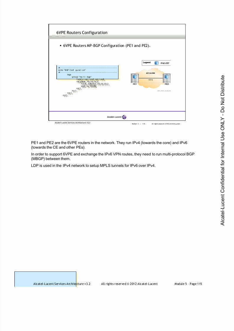
7/21/2019 Services Architecture v3.2 Student Guide Download
http://slidepdf.com/reader/full/services-architecture-v32-student-guide-download 391/429
Alcatel-Lucent Services Architecture v3.2 All rights reserved © 2012 Alcatel-Lucent Module 5 – Page 115
Module 5 | 115 All rights reserved ©2012 Alcatel-LucentAlcatel-Lucent Services Architecture v3.2
6VPE Routers Configuration
6VPE Routers MP-BGP Configuration (PE1 and PE2).
#- - - - - - - - - - - - - - - - - - - - - - - - - - - - - - - - - - - - - - - - - - - - - - - - - -echo "BGP Conf i gur ati on"#- - - - - - - - - - - - - - - - - - - - - - - - - - - - - - - - - - - - - - - - - - - - - - - - - -
bgpgroup "mul t i - bgp"
f ami l y vpn-i pv4 vpn-i pv6neighbor 10. 10. 10. 2
l ocal - address 10. 10. 10. 1peer - as 64496
exi texi t
exi texi t
#- - - - - - - - - - - - - - - - - - - - - - - - - - - - - - - - - - - - - - - - - - - - - - - - - -echo "BGP Conf i gurat i on"#- - - - - - - - - - - - - - - - - - - - - - - - - - - - - - - - - - - - - - - - - - - - - - - - - -
bgpgroup "mul t i - bgp"
f ami l y vpn-i pv4 vpn-i pv6nei ghbor 10. 10. 10. 2
l ocal - address 10. 10. 10. 1peer - as 64496
exi texi t
exi texi t
PE1 and PE2 are the 6VPE routers in the network. They run IPv4 (towards the core) and IPv6
(towards the CE and other PEs).
In order to support 6VPE and exchange the IPv6 VPN routes, they need to run multi-protocol BGP
(MBGP) between them.
LDP is used in the IPv4 network to setup MPLS tunnels for IPv6 over IPv4.

7/21/2019 Services Architecture v3.2 Student Guide Download
http://slidepdf.com/reader/full/services-architecture-v32-student-guide-download 392/429

7/21/2019 Services Architecture v3.2 Student Guide Download
http://slidepdf.com/reader/full/services-architecture-v32-student-guide-download 393/429
Alcatel-Lucent Services Architecture v3.2 All rights reserved © 2012 Alcatel-Lucent Module 5 – Page 117
Module 5 | 117 All rights reserved ©2012 Alcatel-LucentAlcatel-Lucent Services Architecture v3.2
6VPE Verification
Verify that the BGP session to CE is established and VPN IPv6 routes
are exchanged.
*A:PE1# show router 10 bgp summary===============================================================================BGP Rout er I D: 10. 10.10. 1 AS: 64496 Local AS: 64496
===============================================================================BGP Admi n Stat e : Up BGP Oper St ate : Up
Total Peer Gr oups : 1 Total Peer s : 1 Total BGP Pat hs : 6 Total Pat h Memory : 760 Total I Pv4 Remot e Rts : 0 Total I Pv4 Rem. Act i ve Rts : 0Total IPv6 Remote Rts : 3 Total IPv6 Rem. Active Rts : 2
Total Supres sed Rts : 0 Total Hi st . Rts : 0 Total Decay Rts : 0===============================================================================BGP Summar y===============================================================================Nei ghbor
AS PktRcvd I nQ Up/Down State| Rcv/Act/ Sent (Addr Fami l y)PktSent OutQ
- - - - - - - - - - - - - - - - - - - - - - - - - - - - - - - - - - - - - - - - - - - - - - - - - - - - - - - - - - - - - - - - - - - - - - - - - - - - - - -2001:db8:12::1
64497 244 0 01h17m27s 3/ 2/ 3 (IPv6)
238 0===============================================================================
*A:PE1# show router 10 bgp summary===============================================================================BGP Router I D: 10. 10.10. 1 AS: 64496 Local AS: 64496
===============================================================================BGP Admi n Stat e : Up BGP Oper St ate : Up
Tot al Peer Gr oups : 1 Tot al Peers : 1 Tot al BGP Pat hs : 6 Tot al Pat h Memory : 760 Tot al I Pv4 Remot e Rts : 0 Tot al I Pv4 Rem. Act i ve Rts : 0Total IPv6 Remote Rts : 3 Total IPv6 Rem. Active Rts : 2
Tot al Supres sed Rts : 0 Tot al Hi st . Rts : 0 Tot al Decay Rts : 0===============================================================================BGP Summar y===============================================================================Nei ghbor
AS PktRcvd I nQ Up/Down State| Rcv/Act/ Sent (Addr Fami l y)PktSent OutQ
- - - - - - - - - - - - - - - - - - - - - - - - - - - - - - - - - - - - - - - - - - - - - - - - - - - - - - - - - - - - - - - - - - - - - - - - - - - - - - -2001:db8:12::1
64497 244 0 01h17m27s 3/ 2/ 3 (IPv6)
238 0===============================================================================
After the configuration, both IPv6 networks are visible to each other via the 6VPE routers.
The show router 10 bgp summary command can be used at the PE to verify that the BGP session to
CE is established and that VPN IPv6 routes are exchanged.
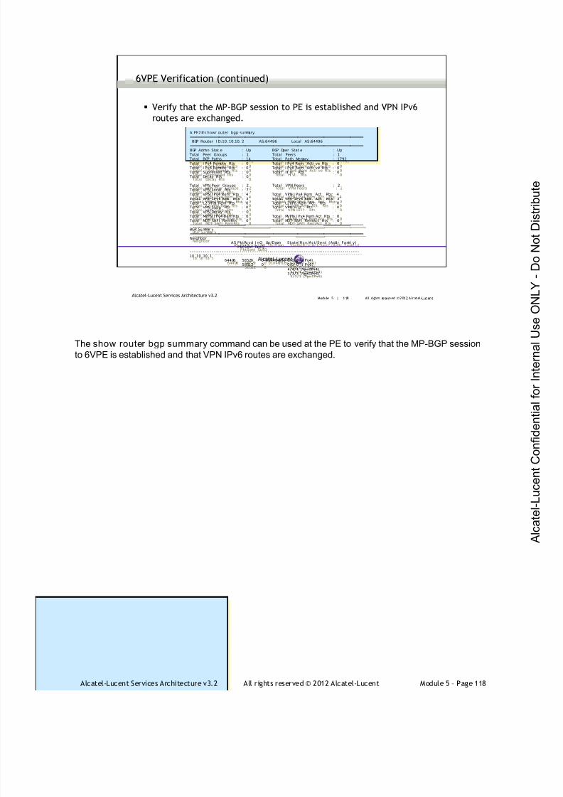
7/21/2019 Services Architecture v3.2 Student Guide Download
http://slidepdf.com/reader/full/services-architecture-v32-student-guide-download 394/429
Alcatel-Lucent Services Architecture v3.2 All rights reserved © 2012 Alcatel-Lucent Module 5 – Page 118
Module 5 | 118 All rights reserved ©2012 Alcatel-LucentAlcatel-Lucent Services Architecture v3.2
6VPE Verification (continued)
Verify that the MP-BGP session to PE is established and VPN IPv6
routes are exchanged.
A:PE2#show router bgp summary
===============================================================================BGP Router I D:10. 10.10. 2 AS:64496 Local AS:64496
===============================================================================BGP Admi n Stat e : Up BGP Oper Stat e : Up
Total Peer Groups : 1 Total Peers : 1 Total BGP Paths : 14 Total Path Memory : 1792 Total I Pv4 Remote Rts : 0 Total I Pv4 Rem. Acti ve Rts : 0 Total I Pv6 Remote Rts : 0 Total I Pv6 Rem. Acti ve Rts : 0 Total Supressed Rts : 0 Total Hi st . Rts : 0 Total Decay Rts : 0
Total VPN Peer Groups : 2 Total VPN Peers : 2 Total VPN Local Rts : 7 Total VPN- I Pv4 Rem. Rts : 4 Total VPN- I Pv4 Rem. Act. Rts: 4Total VPN-IPv6 Rem. Rts : 3 Total VPN-IPv6 Rem. Act. Rts: 3
Total L2-VPN Rem. Rts : 0 Total L2VPN Rem. Act. Rts : 0 Total VPN Supp. Rts : 0 Total VPN His t. Rts : 0 Total VPN Decay Rts : 0 Total MVPN- I Pv4 Rem Rts : 0 Total MVPN- I Pv4 Rem Act Rts : 0 Total MDT- SAFI RemRts : 0 Total MDT- SAFI RemAct Rts : 0===============================================================================BGP Summar y===============================================================================Neighbor
AS PktRcvd I nQ Up/Down State|Rcv/Act/Sent (Addr Fami l y)PktSent OutQ
- - - - - - - - - - -- - - - - - - - - - - -- - - - - - - - - - - -- - - - - - - - - - - -- - - - - - - - - - - - -- - - - - - - - - - - -- - - - - - -10.10.10.1
64496 58529 0 01h46m16s 0/ 0/ 0 (I Pv4)58512 0 0/0/ 0 (I Pv6)
4/4/4 (VpnIPv4)
3/3/3 (VpnIPv6)
A:PE2#s howr outer bgp summary===============================================================================BGP Router I D:10. 10.10. 2 AS:64496 Local AS:64496
===============================================================================BGP Admi n Stat e : Up BGP Oper Stat e : Up
Total Peer Groups : 1 Total Peers : 1 Total BGP Paths : 14 Total Path Memory : 1792 Total I Pv4 Remote Rts : 0 Total I Pv4 Rem. Acti ve Rts : 0 Total I Pv6 Remote Rts : 0 Total I Pv6 Rem. Acti ve Rts : 0 Total Supressed Rts : 0 Total Hi st . Rts : 0 Total Decay Rts : 0
Total VPN Peer Groups : 2 Total VPN Peers : 2 Total VPN Local Rts : 7 Total VPN- I Pv4 Rem. Rts : 4 Total VPN- I Pv4 Rem. Act. Rts: 4Total VPN-IPv6 Rem. Rts : 3 Total VPN-IPv6 Rem. Act. Rts: 3
Total L2-VPN Rem. Rts : 0 Total L2VPN Rem. Act. Rts : 0 Total VPN Supp. Rts : 0 Total VPN Hi st . Rts : 0 Total VPN Decay Rts : 0 Total MVPN- I Pv4 Rem Rts : 0 Total MVPN- I Pv4 Rem Act Rts : 0 Total MDT- SAFI RemRts : 0 Total MDT- SAFI RemAct Rts : 0===============================================================================BGP Summar y===============================================================================Neighbor
AS PktRcvd I nQ Up/Down State|Rcv/Act/Sent (Addr Fami l y)PktSent OutQ
- - - - - - - - - - - - -- - - - - - - - - - - -- - - - - - - - - - - - -- - - - - - - - - - -- - - - - - - - - - - -- - - - - - - - - - - -- - - - - -10.10.10.1
64496 58529 0 01h46m16s 0/ 0/ 0 ( I Pv4)58512 0 0/0/ 0 (I Pv6)
4/4/4 (VpnIPv4)
3/3/3 (VpnIPv6)
The show router bgp summary command can be used at the PE to verify that the MP-BGP session
to 6VPE is established and that VPN IPv6 routes are exchanged.
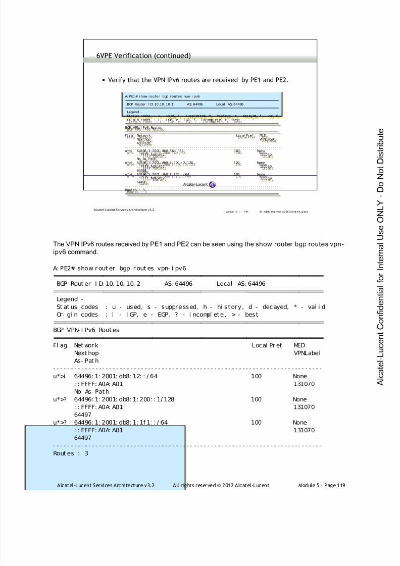
7/21/2019 Services Architecture v3.2 Student Guide Download
http://slidepdf.com/reader/full/services-architecture-v32-student-guide-download 395/429
Alcatel-Lucent Services Architecture v3.2 All rights reserved © 2012 Alcatel-Lucent Module 5 – Page 119
Module 5 | 119 All rights reserved ©2012 Alcatel-LucentAlcatel-Lucent Services Architecture v3.2
6VPE Verification (continued)
Verify that the VPN IPv6 routes are received by PE1 and PE2.
A: PE1# show router bgp routes vpn- i pv6===============================================================================BGP Router I D: 10. 10. 10. 1 AS:64496 Local AS: 64496
===============================================================================Legend -Sta tus codes : u - used, s - suppressed, h - hi s to ry, d - decayed, * - val i dOr i gi n codes : i - I GP , e - EGP, ? - i ncompl ete , > - bes t
===============================================================================BGP VPN- I Pv6 Rout es===============================================================================Flag Network Local Pref MED
Next hop VPNLabelAs-Path
- - - - - - - - - - - - - - - - - - - - - - - - - - - - - - - - - - - - - - - - - - - - - - - - - - - - - - - - - - - - - - - - - - - - - - - - - - - - - - -u*>i 64496: 1: 2001: db8: 56:: / 64 100 None
: : FFFF: A0A:A02 131069No As- Path
u*>? 64496: 1: 2001: db8: 1: 200: : 2/ 128 100 None: : FFFF: A0A:A02 13106964498
u*>? 64496: 1: 2001: db8: 1: 1f2: : / 64 100 None: : FFFF: A0A:A02 13106964498
- - - - - - - - - - - - - - - - - - - - - - - - - - - - - - - - - - - - - - - - - - - - - - - - - - - - - - - - - - - - - - - - - - - - - - - - - - - - - - -Rout es : 3===============================================================================
A: PE1# show router bgp routes vpn- i pv6===============================================================================BGP Router I D: 10.10. 10. 1 AS: 64496 Local AS:64496
===============================================================================Legend -Sta tus codes : u - used, s - suppressed, h - hi s to ry, d - decayed, * - val i dOr i gi n codes : i - I GP, e - EGP, ? - i ncomplete, > - best
===============================================================================BGP VPN- I Pv6 Rout es===============================================================================Flag Network Local Pref MED
Next hop VPNLabelAs-Path
- - - - - - - - - - - - - - - - - - - - - - - - - - - - - - - - - - - - - - - - - - - - - - - - - - - - - - - - - - - - - - - - - - - - - - - - - - - - - - -u*>i 64496: 1: 2001: db8: 56:: / 64 100 None
: : FFFF: A0A:A02 131069No As- Path
u*>? 64496: 1: 2001: db8: 1: 200: : 2/ 128 100 None: : FFFF: A0A:A02 13106964498
u*>? 64496: 1: 2001: db8: 1: 1f2: : / 64 100 None: : FFFF: A0A:A02 13106964498
- - - - - - - - - - - - - - - - - - - - - - - - - - - - - - - - - - - - - - - - - - - - - - - - - - - - - - - - - - - - - - - - - - - - - - - - - - - - - - -Rout es : 3===============================================================================
The VPN IPv6 routes received by PE1 and PE2 can be seen using the show router bgp routes vpn-
ipv6 command.
A: PE2# show r out er bgp r out es vpn- i pv6
=============================================================================
BGP Rout er I D: 10. 10. 10. 2 AS: 64496 Local AS: 64496
=============================================================================
Legend -St at us codes : u - used, s - suppressed, h - hi story, d - decayed, * - val i d
Or i gi n codes : i - I GP, e - EGP, ? - i ncompl ete , > - best
=============================================================================
BGP VPN- I Pv6 Routes
=============================================================================
Fl ag Net wor k Local Pr ef MED
Next hop VPNLabel
As- Pat h
- - - - - - - - - - - - - - - - - - - - - - - - - - - - - - - - - - - - - - - - - - - - - - - - - - - - - - - - - - - - - - - - - - - - - - - - - - - - -
u*>i 64496: 1: 2001: db8: 12: : / 64 100 None
: : FFFF: A0A: A01 131070
No As- Path
u*>? 64496: 1: 2001: db8: 1: 200: : 1/ 128 100 None
: : FFFF: A0A: A01 131070
64497
u*>? 64496: 1: 2001: db8: 1: 1f 1: : / 64 100 None
: : FFFF: A0A: A01 131070
64497
- - - - - - - - - - - - - - - - - - - - - - - - - - - - - - - - - - - - - - - - - - - - - - - - - - - - - - - - - - - - - - - - - - - - - - - - - - - - -
Rout es : 3
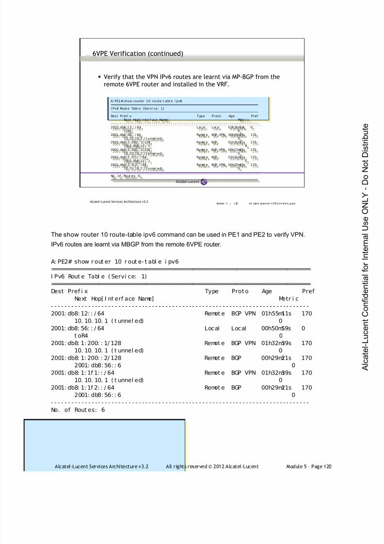
7/21/2019 Services Architecture v3.2 Student Guide Download
http://slidepdf.com/reader/full/services-architecture-v32-student-guide-download 396/429
Alcatel-Lucent Services Architecture v3.2 All rights reserved © 2012 Alcatel-Lucent Module 5 – Page 120
Module 5 | 120 All rights reserved ©2012 Alcatel-LucentAlcatel-Lucent Services Architecture v3.2
6VPE Verification (continued)
Verify that the VPN IPv6 routes are learnt via MP-BGP from the
remote 6VPE router and installed in the VRF.
A:PE1# show router 10 route-t abl e i pv6===============================================================================I Pv6 Rout e Tabl e (Servi ce: 1)===============================================================================Dest Prefi x Type Proto Age Pref
Next Hop[ I nter f ace Name] Metr i c- - - - - - - - - - - - - - - - - - - - - - - - - - - - - - - - - - - - - - - - - - - - - - - - - - - - - - - - - - - - - - - - - - - - - - - - - - - - - - -2001: db8:12: : / 64 Local Local 02h16m34s 0
t oR3 02001: db8: 56: : / 64 Remot e BGP VPN 00h49m29s 170
10. 10. 10. 2 ( t unnel ed) 02001: db8:1: 200: : 1/ 128 Remot e BGP 01h31m32s 170
2001: db8:12:: 1 02001: db8: 1: 200: : 2/ 128 Remot e BGP VPN 00h27m49s 170
10. 10. 10. 2 ( t unnel ed) 02001: db8:1: 1f 1: : / 64 Remot e BGP 01h31m32s 170
2001: db8:12:: 1 02001: db8:1: 1f 2: : / 64 Remot e BGP VPN 00h27m49s 170
10. 10. 10. 2 ( t unnel ed) 0- - - - - - - - - - - - - - - - - - - - - - - - - - - - - - - - - - - - - - - - - - - - - - - - - - - - - - - - - - - - - - - - - - - - - - - - - - - - - - -No. of Routes: 6===============================================================================
A: PE1#show router 10 route-t abl e i pv6===============================================================================I Pv6 Rout e Tabl e (Servi ce: 1)===============================================================================Dest Prefi x Type Proto Age Pref
Next Hop[ I nter f ace Name] Metr i c- - - - - - - - - - - - - - - - - - - - - - - - - - - - - - - - - - - - - - - - - - - - - - - - - - - - - - - - - - - - - - - - - - - - - - - - - - - - - - -2001: db8:12: : / 64 Local Local 02h16m34s 0
t oR3 02001: db8: 56: : / 64 Remot e BGP VPN 00h49m29s 170
10. 10. 10. 2 ( t unnel ed) 02001: db8:1: 200: : 1/ 128 Remot e BGP 01h31m32s 170
2001: db8:12:: 1 02001: db8: 1: 200: : 2/ 128 Remot e BGP VPN 00h27m49s 170
10. 10. 10. 2 ( t unnel ed) 02001: db8:1: 1f 1: : / 64 Remot e BGP 01h31m32s 170
2001: db8:12:: 1 02001: db8:1: 1f 2: : / 64 Remot e BGP VPN 00h27m49s 170
10. 10. 10. 2 ( t unnel ed) 0- - - - - - - - - - - - - - - - - - - - - - - - - - - - - - - - - - - - - - - - - - - - - - - - - - - - - - - - - - - - - - - - - - - - - - - - - - - - - - -No. of Rout es: 6===============================================================================
The show router 10 route-table ipv6 command can be used in PE1 and PE2 to verify VPN.
IPv6 routes are learnt via MBGP from the remote 6VPE router.
A: PE2# show r out er 10 r out e- t abl e i pv6
=============================================================================
I Pv6 Rout e Tabl e ( Servi ce: 1)
=============================================================================Dest Pref i x Type Prot o Age Pref
Next Hop[ I nt erf ace Name] Metr i c
- - - - - - - - - - - - - - - - - - - - - - - - - - - - - - - - - - - - - - - - - - - - - - - - - - - - - - - - - - - - - - - - - - - - - - - - - - - - -
2001: db8: 12: : / 64 Remot e BGP VPN 01h55m11s 170
10. 10. 10. 1 ( t unnel ed) 0
2001: db8: 56: : / 64 Local Local 00h50m59s 0
t oR4 0
2001: db8: 1: 200: : 1/ 128 Remot e BGP VPN 01h32m39s 170
10. 10. 10. 1 ( t unnel ed) 0
2001: db8: 1: 200: : 2/ 128 Remot e BGP 00h29m21s 170
2001: db8: 56: : 6 0
2001: db8: 1: 1f 1: : / 64 Remot e BGP VPN 01h32m39s 170
10. 10. 10. 1 ( t unnel ed) 02001: db8: 1: 1f 2: : / 64 Remot e BGP 00h29m21s 170
2001: db8: 56: : 6 0
- - - - - - - - - - - - - - - - - - - - - - - - - - - - - - - - - - - - - - - - - - - - - - - - - - - - - - - - - - - - - - - - - - - - - - - - - - - - -
No. of Rout es: 6
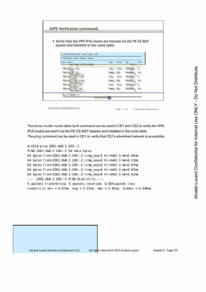
7/21/2019 Services Architecture v3.2 Student Guide Download
http://slidepdf.com/reader/full/services-architecture-v32-student-guide-download 397/429
Alcatel-Lucent Services Architecture v3.2 All rights reserved © 2012 Alcatel-Lucent Module 5 – Page 121
Module 5 | 121 All rights reserved ©2012 Alcatel-LucentAlcatel-Lucent Services Architecture v3.2
6VPE Verification (continued)
Verify that the VPN IPv6 routes are learned via the PE-CE BGP
session and installed in the route table.
A: CE1# show router route-t abl e i pv6===============================================================================I Pv6 Route Tabl e ( Rout er: Base)===============================================================================Dest Prefi x Type Proto Age Pref
Next Hop[ I nterf ace Name] Metr i c- - - - - - - - - - - - - - - - - - - - - - - - - - - - - - - - - - - - - - - - - - - - - - - - - - - - - - - - - - - - - - - - - - - - - - - - - - - - - - -2001: db8:12: : / 64 Local Local 02h06m09s 0
t oR1 02001:db8: 56: : / 64 Remot e BGP 00h46m54s 170
2001: db8:12:: 2 02001: db8:1:200:: 1/128 Local Local 01h29m24s 0
system 02001: db8: 1: 200: : 2/ 128 Remot e BGP 00h25m21s 170
2001: db8:12:: 2 02001: db8: 1: 1f1:: / 64 Local Local 01d02h10m 0
Bl ueSit e1 02001: db8: 1: 1f 2: : / 64 Remot e BGP 00h25m21s 170
2001: db8:12:: 2 0- - - - - - - - - - - - - - - - - - - - - - - - - - - - - - - - - - - - - - - - - - - - - - - - - - - - - - - - - - - - - - - - - - - - - - - - - - - - - - -No. of Rout es: 6===============================================================================
A: CE1# show router route-t abl e i pv6===============================================================================I Pv6 Route Tabl e ( Rout er: Base)===============================================================================Dest Prefi x Type Proto Age Pref
Next Hop[ I nterf ace Name] Metr i c- - - - - - - - - - - - - - - - - - - - - - - - - - - - - - - - - - - - - - - - - - - - - - - - - - - - - - - - - - - - - - - - - - - - - - - - - - - - - - -2001: db8:12: : / 64 Local Local 02h06m09s 0
t oR1 02001: db8: 56: : / 64 Remot e BGP 00h46m54s 170
2001: db8:12:: 2 02001: db8:1:200: : 1/128 Local Local 01h29m24s 0
system 02001: db8: 1: 200: : 2/ 128 Remot e BGP 00h25m21s 170
2001: db8:12:: 2 02001: db8:1:1f1: : / 64 Local Local 01d02h10m 0
BlueSi te1 02001: db8: 1: 1f 2: : / 64 Remot e BGP 00h25m21s 170
2001: db8:12:: 2 0- - - - - - - - - - - - - - - - - - - - - - - - - - - - - - - - - - - - - - - - - - - - - - - - - - - - - - - - - - - - - - - - - - - - - - - - - - - - - - -No. of Routes: 6===============================================================================
The show router route-table ipv6 command can be used in CE1 and CE2 to verify the VPN.
IPv6 routes are learnt via the PE-CE BGP session and installed in the route table.
The ping command can be used in CE1 to verify that CE2’s advertised network is accessible.
A: CE1# pi ng 2001: db8: 1: 200: : 2
PI NG 2001: db8: 1: 200: : 2 56 dat a byt es
64 byt es f r om 2001: db8: 1: 200: : 2 i cmp_seq=1 hl i m=62 t i me=2. 80ms.
64 byt es f r om 2001: db8: 1: 200: : 2 i cmp_seq=2 hl i m=62 t i me=3. 13ms.
64 byt es f r om 2001: db8: 1: 200: : 2 i cmp_seq=3 hl i m=62 t i me=2. 67ms.
64 byt es f r om 2001: db8: 1: 200: : 2 i cmp_seq=4 hl i m=62 t i me=3. 82ms.
64 byt es f r om 2001: db8: 1: 200: : 2 i cmp_seq=5 hl i m=62 t i me=3. 61ms.
- - - - 2001: db8: 1: 200: : 2 PI NG St at i sti cs - - - -
5 packet s t r ansmi t t ed, 5 packet s r ecei ved, 0. 00% packet l oss
r ound- t r i p mi n = 2. 67ms, avg = 3. 21ms, max = 3. 82ms, st ddev = 0. 448ms

7/21/2019 Services Architecture v3.2 Student Guide Download
http://slidepdf.com/reader/full/services-architecture-v32-student-guide-download 398/429
Alcatel-Lucent Services Architecture v3.2 All rights reserved © 2012 Alcatel-Lucent Module 5 – Page 122
Module 5 | 122 All rights reserved ©2012 Alcatel-LucentAlcatel-Lucent Services Architecture v3.2
6VPE Verification (continued)
Verify that the IPv6 route is learned via M-BGP over the IPv4 core.
*A:PE1# show rout er bgp rout es 64496:1: 2001: db8: 1:200: : 2/128 hunt===============================================================================BGP Router I D: 10.10. 10. 1 AS: 64496 Local AS:64496
===============================================================================Legend -Sta tus codes : u - used, s - suppressed, h - hi s to ry, d - decayed, * - val i dOr i gi n codes : i - I GP, e - EGP, ? - i ncompl ete , > - bes t
===============================================================================BGP VPN- I Pv6 Rout es- - - - - - - - - - - - - - - - - - - - - - - - - - - - - - - - - - - - - - - - - - - - - - - - - - - - - - - - - - - - - - - - - - - - - - - - - - - - - - -RI B I n Entr i es- - - - - - - - - - - - - - - - - - - - - - - - - - - - - - - - - - - - - - - - - - - - - - - - - - - - - - - - - - - - - - - - - - - - - - - - - - - - - - -Network : 2001: db8:1: 200:: 2/128
Nexthop : ::FFFF:A0A:A02
Route Di st . : 64496: 1 VPN Label : 131069From : 10. 10. 10. 2Res . Next hop : n/ aLocal Pref . : 100 I nterf ace Name : NotAvai l abl eAggregat or AS : None Aggregat or : NoneAtomi c Aggr. : Not Atomi c MED : NoneCommuni t y : t arget : 64496: 10Cl ust er : No Cl ust er MembersOri ginator I d : None Peer Router I d : 10. 10. 10. 2Fl ags : Used Val i d Best I ncompl eteAS- Path : 64498VPRN I mport ed : 1- - - - - - - - - - - - - - - - - - - - - - - - - - - - - - - - - - - - - - - - - - - - - - - - - - - - - - - - - - - - - - - - - - - - - - - - - - - - - - -
*A:PE1# show router bgp rout es 64496:1: 2001: db8:1: 200:: 2/128 hunt===============================================================================
BGP Rout er I D: 10. 10. 10. 1 AS: 64496 Local AS: 64496===============================================================================Legend -Sta tus codes : u - used, s - suppressed, h - hi s to ry, d - decayed, * - val i dOr i gi n codes : i - I GP, e - EGP, ? - i ncompl ete, > - best
===============================================================================BGP VPN- I Pv6 Routes- - - - - - - - - - - - - - - - - - - - - - - - - - - - - - - - - - - - - - - - - - - - - - - - - - - - - - - - - - - - - - - - - - - - - - - - - - - - - - -RI B In Entr i es- - - - - - - - - - - - - - - - - - - - - - - - - - - - - - - - - - - - - - - - - - - - - - - - - - - - - - - - - - - - - - - - - - - - - - - - - - - - - - -Network : 2001: db8:1: 200:: 2/128
Nexthop : ::FFFF:A0A:A02
Route Di st . : 64496: 1 VPN Label : 131069From : 10. 10. 10. 2Res . Next hop : n/ aLocal Pref. : 100 I nterf ace Name : NotAvail abl eAggregat or AS : None Aggregat or : NoneAtomi c Aggr . : Not Atomi c MED : NoneCommuni t y : t arget : 64496: 10Cl ust er : No Cl ust er MembersOri ginator I d : None Peer Router I d : 10. 10. 10. 2Fl ags : Used Val i d Best I ncompl eteAS- Path : 64498VPRN I mpor t ed : 1- - - - - - - - - - - - - - - - - - - - - - - - - - - - - - - - - - - - - - - - - - - - - - - - - - - - - - - - - - - - - - - - - - - - - - - - - - - - - - -
The show router bgp routes 64496:1:2001:db8:1:200::2/128 hunt command can be used to verify
that the IPv6 route is learnt via M-BGP over the IPv4 core.
The next-hop for the route is an IPv4-mapped IPv6 route.
This command also displays the VPN label 131069 used for 6VPE (remember from IPv4 MPLS VPNs
that we use platform-based labeling).
Note: that BGP must have a valid next hop for the route before it is installed in the route table. If theMPLS transport in the VPRN (auto-bind ldp in this case) has not been configured, then the route will
be marked as Invalid and not used by BGP as there is no transport tunnel to the next hop.

7/21/2019 Services Architecture v3.2 Student Guide Download
http://slidepdf.com/reader/full/services-architecture-v32-student-guide-download 399/429
Alcatel-Lucent Services Architecture v3.2 All rights reserved © 2012 Alcatel-Lucent Module 5 – Page 123
Module 5 | 123 All rights reserved ©2012 Alcatel-LucentAlcatel-Lucent Services Architecture v3.2
Lab 10: IPv6 VPRN
In this lab you will configure and verify IPv6 VPRNs
AS 64497
Blue VPN Site 1
AS 64500
Red VPN Site 2
AS 64499
Red VPN Site 1
AS 64498
Blue VPN Site 2
BGP
BGP
MP-BGP
LDP
Pod 1Pod 2
Pod 3 Pod 4
In this lab, students will configure and verify IPv6 VPN (6VPE) routing over IPv4 MPLS infrastructure
with BGP routing between CE and PE.
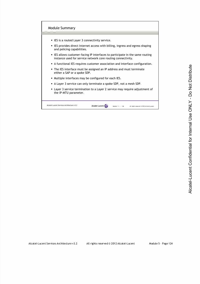
7/21/2019 Services Architecture v3.2 Student Guide Download
http://slidepdf.com/reader/full/services-architecture-v32-student-guide-download 400/429
Alcatel-Lucent Services Architecture v3.2 All rights reserved © 2012 Alcatel-Lucent Module 5 – Page 124
Module 5 | 124 All rights reserved ©2012 Alcatel-LucentAlcatel-Lucent Services Architecture v3.2
Module Summary
IES is a routed Layer 3 connectivity service.
IES provides direct Internet access with billing, ingress and egress shaping
and policing capabilities.
IES allows customer-facing IP interfaces to participate in the same routing
instance used for service network core routing connectivity.
A functional IES requires customer association and interface configuration.
The IES interface must be assigned an IP address and must terminate
either a SAP or a spoke SDP.
Multiple interfaces may be configured for each IES.
A Layer 3 service can only terminate a spoke SDP, not a mesh SDP.
Layer 3 service termination to a Layer 2 service may require adjustment of
the IP-MTU parameter.
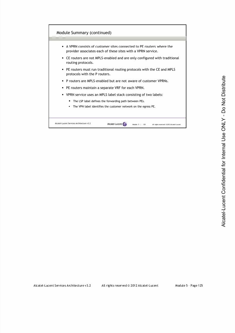
7/21/2019 Services Architecture v3.2 Student Guide Download
http://slidepdf.com/reader/full/services-architecture-v32-student-guide-download 401/429
Alcatel-Lucent Services Architecture v3.2 All rights reserved © 2012 Alcatel-Lucent Module 5 – Page 125
Module 5 | 125 All rights reserved ©2012 Alcatel-LucentAlcatel-Lucent Services Architecture v3.2
Module Summary (continued)
A VPRN consists of customer sites connected to PE routers where the
provider associates each of these sites with a VPRN service.
CE routers are not MPLS-enabled and are only configured with traditionalrouting protocols.
PE routers must run traditional routing protocols with the CE and MPLS
protocols with the P routers.
P routers are MPLS-enabled but are not aware of customer VPRNs.
PE routers maintain a separate VRF for each VPRN.
VPRN service uses an MPLS label stack consisting of two labels:
The LSP label defines the forwarding path between PEs.
The VPN label identifies the customer network on the egress PE.

7/21/2019 Services Architecture v3.2 Student Guide Download
http://slidepdf.com/reader/full/services-architecture-v32-student-guide-download 402/429
Alcatel-Lucent Services Architecture v3.2 All rights reserved © 2012 Alcatel-Lucent Module 5 – Page 126
Module 5 | 126 All rights reserved ©2012 Alcatel-LucentAlcatel-Lucent Services Architecture v3.2
Module Summary (continued)
VPN-IPv4 addresses were created to extend BGP’s ability to carry
overlapping routing information.
VPN-IPv4 addresses are carried only across the provider's backbone by theMP-BGP protocol.
A VPN-IPv4 address is a 12-byte value consisting of an 8-byte route
distinguisher (RD) and a 4-byte IPv4 prefix.
The 8-byte route target (RT) is a BGP-extended community attribute used
as the VPN identifier.
LSP label signaling is exchanged between provider core routers via RSVP-
TE or LDP.
PE routers exchange the routing information learned from all customer
sites via MP-BGP.
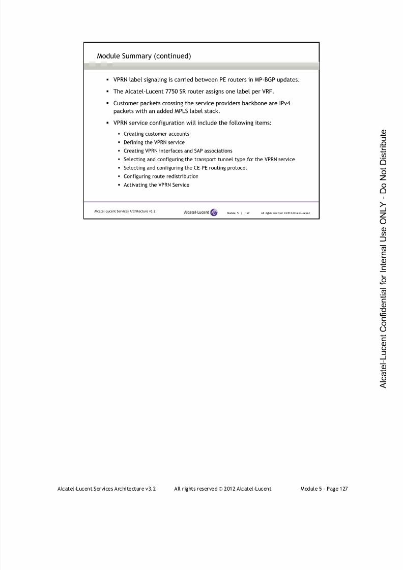
7/21/2019 Services Architecture v3.2 Student Guide Download
http://slidepdf.com/reader/full/services-architecture-v32-student-guide-download 403/429
Alcatel-Lucent Services Architecture v3.2 All rights reserved © 2012 Alcatel-Lucent Module 5 – Page 127
Module 5 | 127 All rights reserved ©2012 Alcatel-LucentAlcatel-Lucent Services Architecture v3.2
Module Summary (continued)
VPRN label signaling is carried between PE routers in MP-BGP updates.
The Alcatel-Lucent 7750 SR router assigns one label per VRF.
Customer packets crossing the service providers backbone are IPv4
packets with an added MPLS label stack.
VPRN service configuration will include the following items:
Creating customer accounts
Defining the VPRN service
Creating VPRN interfaces and SAP associations
Selecting and configuring the transport tunnel type for the VPRN service
Selecting and configuring the CE-PE routing protocol
Configuring route redistribution
Activating the VPRN Service

7/21/2019 Services Architecture v3.2 Student Guide Download
http://slidepdf.com/reader/full/services-architecture-v32-student-guide-download 404/429
Alcatel-Lucent Services Architecture v3.2 All rights reserved © 2012 Alcatel-Lucent Module 5 – Page 128
Module 5 | 128 All rights reserved ©2012 Alcatel-LucentAlcatel-Lucent Services Architecture v3.2
Module Summary (continued)
6VPE is a tunneling technology that makes use of MPLS tunnels to
transport IPv6 information over the IPv4 MPLS infrastructure.
In 6VPE, the PE routers run a dual stack of IPv4/IPv6 and exchange the
IPv6 routes using MP-BGP.
As in IPv4 VPRN, MP-BGP is used to distribute routes from an IPv6 VPN site
to all the other PE routers connected to a site of the same IPv6 VPN.
PEs use VPN routing and forwarding tables (VRFs) to maintain the
reachability and forwarding information for each IPv6 VPN separately.

7/21/2019 Services Architecture v3.2 Student Guide Download
http://slidepdf.com/reader/full/services-architecture-v32-student-guide-download 405/429
Alcatel-Lucent Services Architecture v3.2 All rights reserved © 2012 Alcatel-Lucent Module 5 – Page 129
Module 5 | 129 All rights reserved ©2012 Alcatel-LucentAlcatel-Lucent Services Architecture v3.2
Learning Assessment
1. Verify whether the following statement is true or false: An IES must
be configured with a SAP and an SDP.
2. Verify whether the following statement is true or false: An IES maybe configured to either a SAP or on a network port.
3. When an IES is used to provide a Layer 3 termination for a SAP,
what extra configuration is necessary within the SAP?
4. When an IES is used to terminate the spoke SDP of a VPLS, what
extra configuration must be done on the VPLS side?
5. When an IES is used to terminate the spoke SDP of a VPLS, what
extra configuration must be done on the IES side?
6. When an IES is used to terminate the spoke SDP of a VPLS, what
MAC address appears in the VPLS FDB for the IES interface?
1. Verify whether the following statement is true or false: An IES is configured with a SAP and a SDP.
False
2. Verify whether the following statement is true or false: An IES may configured to either a
SAP or on a network port.
False; it cannot be configured on a network port.
3. When an IES is used to provide a Layer 3 termination for a SAP, what extra configuration is
necessary within the SAP?
No extra configuration is required for the SAP.
4. When an IES is used to terminate the spoke SDP of a VPLS, what extra configuration must be done
on the VPLS side?
No extra configuration is required within the VPLS.
5. When an IES is used to terminate the spoke SDP of a VPLS, what extra configuration must done on
the IES side?
The VC MTU must match on both sides of the spoke SDP, so it will typically be necessary to
define the IP-MTU setting for each interface within the IES.
6. When an IES is used to terminate the spoke SDP of a VPLS, what MAC address appears in the
VPLS FDB for the IES interface?
The MAC address of the IES corresponds to the base chassis MAC address of the IES router.
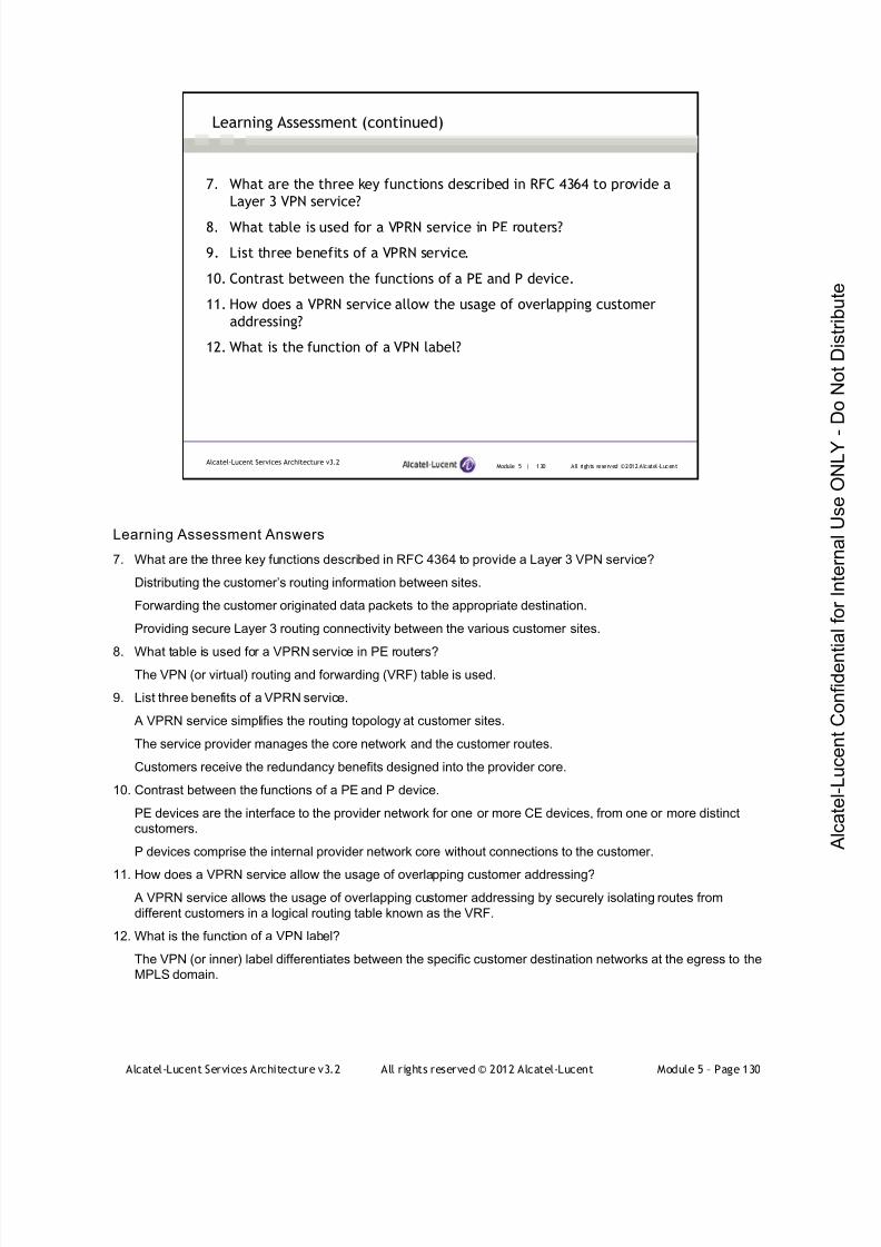
7/21/2019 Services Architecture v3.2 Student Guide Download
http://slidepdf.com/reader/full/services-architecture-v32-student-guide-download 406/429
Alcatel-Lucent Services Architecture v3.2 All rights reserved © 2012 Alcatel-Lucent Module 5 – Page 130
Module 5 | 130 All rights reserved ©2012 Alcatel-LucentAlcatel-Lucent Services Architecture v3.2
Learning Assessment (continued)
7. What are the three key functions described in RFC 4364 to provide a
Layer 3 VPN service?
8. What table is used for a VPRN service in PE routers?
9. List three benefits of a VPRN service.
10. Contrast between the functions of a PE and P device.
11. How does a VPRN service allow the usage of overlapping customer
addressing?
12. What is the function of a VPN label?
Learning Assessment Answers
7. What are the three key functions described in RFC 4364 to provide a Layer 3 VPN service?
Distributing the customer’s routing information between sites.
Forwarding the customer originated data packets to the appropriate destination.
Providing secure Layer 3 routing connectivity between the various customer sites.
8. What table is used for a VPRN service in PE routers?The VPN (or virtual) routing and forwarding (VRF) table is used.
9. List three benefits of a VPRN service.
A VPRN service simplifies the routing topology at customer sites.
The service provider manages the core network and the customer routes.
Customers receive the redundancy benefits designed into the provider core.
10. Contrast between the functions of a PE and P device.
PE devices are the interface to the provider network for one or more CE devices, from one or more distinct
customers.
P devices comprise the internal provider network core without connections to the customer.
11. How does a VPRN service allow the usage of overlapping customer addressing?
A VPRN service allows the usage of overlapping customer addressing by securely isolating routes from
different customers in a logical routing table known as the VRF.
12. What is the function of a VPN label?
The VPN (or inner) label differentiates between the specific customer destination networks at the egress to the
MPLS domain.
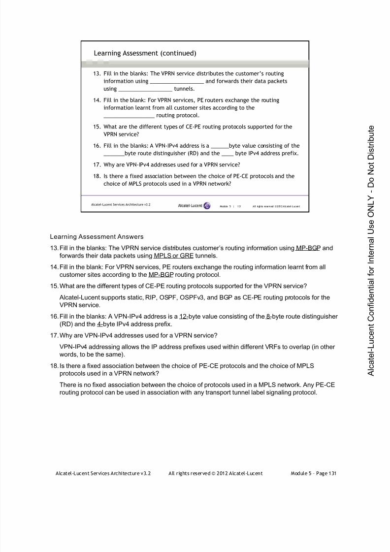
7/21/2019 Services Architecture v3.2 Student Guide Download
http://slidepdf.com/reader/full/services-architecture-v32-student-guide-download 407/429
Alcatel-Lucent Services Architecture v3.2 All rights reserved © 2012 Alcatel-Lucent Module 5 – Page 131
Module 5 | 131 All rights reserved ©2012 Alcatel-LucentAlcatel-Lucent Services Architecture v3.2
Learning Assessment (continued)
13. Fill in the blanks: The VPRN service distributes the customer’s routing
information using __________________ and forwards their data packets
using __________________ tunnels.
14. Fill in the blank: For VPRN services, PE routers exchange the routing
information learnt from all customer sites according to the
_________________ routing protocol.
15. What are the different types of CE-PE routing protocols supported for the
VPRN service?
16. Fill in the blanks: A VPN-IPv4 address is a ______byte value consisting of the
_______byte route distinguisher (RD) and the ____ byte IPv4 address prefix.
17. Why are VPN-IPv4 addresses used for a VPRN service?
18. Is there a fixed association between the choice of PE-CE protocols and the
choice of MPLS protocols used in a VPRN network?
Learning Assessment Answers
13.Fill in the blanks: The VPRN service distributes customer’s routing information using MP-BGP and
forwards their data packets using MPLS or GRE tunnels.
14.Fill in the blank: For VPRN services, PE routers exchange the routing information learnt from all
customer sites according to the MP-BGP routing protocol.
15.What are the different types of CE-PE routing protocols supported for the VPRN service?
Alcatel-Lucent supports static, RIP, OSPF, OSPFv3, and BGP as CE-PE routing protocols for the
VPRN service.
16.Fill in the blanks: A VPN-IPv4 address is a 12-byte value consisting of the 8-byte route distinguisher
(RD) and the 4-byte IPv4 address prefix.
17.Why are VPN-IPv4 addresses used for a VPRN service?
VPN-IPv4 addressing allows the IP address prefixes used within different VRFs to overlap (in other
words, to be the same).
18. Is there a fixed association between the choice of PE-CE protocols and the choice of MPLS
protocols used in a VPRN network?
There is no fixed association between the choice of protocols used in a MPLS network. Any PE-CErouting protocol can be used in association with any transport tunnel label signaling protocol.
7/21/2019 Services Architecture v3.2 Student Guide Download
http://slidepdf.com/reader/full/services-architecture-v32-student-guide-download 408/429
Alcatel-Lucent Services Architecture v3.2 All rights reserved © 2012 Alcatel-Lucent Module 5 – Page 132
Module 5 | 132 All rights reserved ©2012 Alcatel-LucentAlcatel-Lucent Services Architecture v3.2
Learning Assessment (continued)
19. What is the purpose of a route target (RT)?
20. How is a BGP session configured to carry VPN-IPv4 prefixes?
21. Will the VPRN PE-CE interface be operationally active if the routedistinguisher is not configured?
22. What is a dual stack router?
23. What routing tables are used by a 6VPE router?
Learning Assessment Answers
19. What is the purpose of a route target (RT)?
The route target (RT) provides the ability for MP-BGP to install the routes into the correct egress VRF table.
20. How is a BGP session configured to carry VPN-IPv4 prefixes?
A BGP session is configured to carry VPN-IPv4 prefixes by defining the 'family vpn-ipv4‘ parameter
under the BGP configuration.21. Will the VPRN service be operationally active if the route distinguisher is not configured?
A route distinguisher must be defined in order for VPRN PE-CE interface to be operationally active.
22. What is a dual stack router?
Dual stack means that a router can support both IPv4 and IPv6 protocol stacks. Such a router can
communicate with an IPv4 and IPv6 router directly. Therefore, it can be regarded as a connection point
between IPv4 and IPv6 networks.
23. What routing tables are used by a 6VPE router?
IPv6 VRFs: a set of customer-specific IPv6 routing tables that contains customer routes. Each of these routing
tables contains routes received from the CE routers as well as routes from remote sites in the same VPN.
A defaul t routing table that is exclusively used to reach routers inside the provider network.
A BGP table that contains entries from all the customer-specific IPv6 routes.

7/21/2019 Services Architecture v3.2 Student Guide Download
http://slidepdf.com/reader/full/services-architecture-v32-student-guide-download 409/429
Alcatel-Lucent Services Architecture v3.2 All rights reserved © 2012 Alcatel-Lucent Module 5 – Page 133
Appendix — IPv6
This appendix is provided as supplementary material for students who did not take the latest IRP course
version. Its material is not part of the services exam.

7/21/2019 Services Architecture v3.2 Student Guide Download
http://slidepdf.com/reader/full/services-architecture-v32-student-guide-download 410/429
Alcatel-Lucent Services Architecture v3.2 All rights reserved © 2012 Alcatel-Lucent Module 5 – Page 134
Module 5 | 134 All rights reserved ©2012 Alcatel-LucentAlcatel-Lucent Services Architecture v3.2
Appendix Overview
IPv6 addressing
ICMPv6
Configuring IPv6 interfaces on Alcatel-Lucent 7750 SR
Alcatel-Lucent Services Archi tecture
This course is part of the Alcatel-Lucent Service Routing Certification (SRC) program. Refer to the
Alcatel-Lucent website located at www.alcatel-lucent.com/src for more information on the SRC program.
To locate additional information relating to the topics presented in this manual, refer to the following:
• Technical Practices for the specific product
• Internet standards documentation such as protocol standards bodies, RFCs, and IETF drafts
• Technical support pages of the Alcatel-Lucent website located at http://www.alcatel-
lucent.com/support
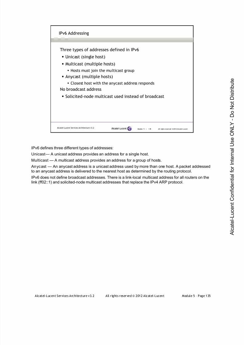
7/21/2019 Services Architecture v3.2 Student Guide Download
http://slidepdf.com/reader/full/services-architecture-v32-student-guide-download 411/429
Alcatel-Lucent Services Architecture v3.2 All rights reserved © 2012 Alcatel-Lucent Module 5 – Page 135
Module 5 | 135 All rights reserved ©2012 Alcatel-LucentAlcatel-Lucent Services Architecture v3.2
IPv6 Addressing
Three types of addresses defined in IPv6
Unicast (single host)
Multicast (multiple hosts)
Hosts must join the multicast group
Anycast (multiple hosts)
Closest host with the anycast address responds
No broadcast address
Solicited-node multicast used instead of broadcast
IPv6 defines three different types of addresses:
Unicast — A unicast address provides an address for a single host.
Multicast — A multicast address provides an address for a group of hosts.
Anycast — An anycast address is a unicast address used by more than one host. A packet addressed
to an anycast address is delivered to the nearest host as determined by the routing protocol.
IPv6 does not define broadcast addresses. There is a link-local multicast address for all routers on the
link (ff02::1) and solicited-node multicast addresses that replace the IPv4 ARP protocol.

7/21/2019 Services Architecture v3.2 Student Guide Download
http://slidepdf.com/reader/full/services-architecture-v32-student-guide-download 412/429
Alcatel-Lucent Services Architecture v3.2 All rights reserved © 2012 Alcatel-Lucent Module 5 – Page 136
Module 5 | 136 All rights reserved ©2012 Alcatel-LucentAlcatel-Lucent Services Architecture v3.2
IPv6 Addressing
IPv6 is 128 bits, expressed in groups of 4 hex digits
Eg. 2001:0db8:0000:0000:0021:0000:4ab9:0300
One or more groups of consecutive zeroes can be omitted
Only one group can be omitted
Eg. 2001:0db8::0021:0000:4ab9:0300
Leading zeroes can be omitted
Eg. 2001:db8::21:0:4ab9:300
Since the IPv6 address is 128 bits, there are a number of conventions used to shorten them as much as
possible.
1. Addresses are written in groups of 4 hex digits, separated by a single colon. For example
2001:0db8:0000:0000:0021:0000:4ab9:0300.
2. One or more groups of zeroes can be replaced by two colons. The number above becomes
2001:0db8::0021:0000: 4ab9:0300.
3. Only one group of zeroes can be replaced with double colons. Otherwise it would not possible to tellwhere the zeroes are located. However, leading zeroes in a group can also be omitted. The address
above becomes 2001:db8::21:0: 4ab9:300.

7/21/2019 Services Architecture v3.2 Student Guide Download
http://slidepdf.com/reader/full/services-architecture-v32-student-guide-download 413/429
Alcatel-Lucent Services Architecture v3.2 All rights reserved © 2012 Alcatel-Lucent Module 5 – Page 137
Module 5 | 137 All rights reserved ©2012 Alcatel-LucentAlcatel-Lucent Services Architecture v3.2
Unicast Addresses
64 bits for routing prefix
48 bit global prefix
16 bit subnet
2000::/3 is reserved as the global routing prefix
64 bits for interface identifier
May be derived from MAC address
Regular IPv6 unicast addressing uses a fixed structure where 64 bits are defined as the routing prefix
and 64 bits are defined as the interface identifier. For a globally routed address, 48 bits of the routing
prefix are used as the global routing prefix and 16 bits are the local routing prefix (or subnet).
The allocation for globally routed IPv6 addresses is the address space 2000::/3. This represents one
eighth of the entire address space and is all addresses beginning with the bit pattern 001. An ISP is
typically allocated a network assignment of /32 or larger (larger means a smaller prefix such as /31 or 30
and hence a larger network range). An individual enterprise typically receives a /48 or larger. Since a /48
has 16 bits available for the local subnet, this provides 65,536 individual subnets.
The interface ID portion of the address is locally assigned, but can be automatically derived from the 48
bit MAC address. It might also be assigned from a DHCPv6 server, through an auto-discovery
mechanism or manually assigned.
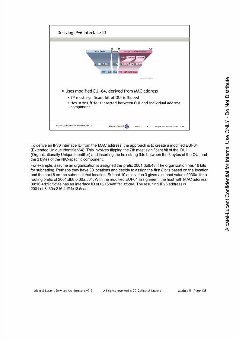
7/21/2019 Services Architecture v3.2 Student Guide Download
http://slidepdf.com/reader/full/services-architecture-v32-student-guide-download 414/429
Alcatel-Lucent Services Architecture v3.2 All rights reserved © 2012 Alcatel-Lucent Module 5 – Page 138
Module 5 | 138 All rights reserved ©2012 Alcatel-LucentAlcatel-Lucent Services Architecture v3.2
Deriving IPv6 Interface ID
Uses modified EUI-64, derived from MAC address
7th most significant bit of OUI is flipped
Hex string ff:fe is inserted between OUI and individual addresscomponent
To derive an IPv6 interface ID from the MAC address, the approach is to create a modified EUI-64
(Extended Unique Identifier-64). This involves flipping the 7th most significant bit of the OUI
(Organizationally Unique Identifier) and inserting the hex string ff:fe between the 3 bytes of the OUI and
the 3 bytes of the NIC-specific component.
For example, assume an organization is assigned the prefix 2001:db8/48. The organization has 16 bits
for subnetting. Perhaps they have 30 locations and decide to assign the first 8 bits based on the location
and the next 8 on the subnet at that location. Subnet 10 at location 3 gives a subnet value of 030a, for a
routing prefix of 2001:db8:0:30a::/64. With the modified EUI-64 assignment, the host with MAC address00:16:4d:13:5c:ae has an interface ID of 0216:4dff:fe13:5cae. The resulting IPv6 address is
2001:db8::30a:216:4dff:fe13:5cae.

7/21/2019 Services Architecture v3.2 Student Guide Download
http://slidepdf.com/reader/full/services-architecture-v32-student-guide-download 415/429
Alcatel-Lucent Services Architecture v3.2 All rights reserved © 2012 Alcatel-Lucent Module 5 – Page 139
Module 5 | 139 All rights reserved ©2012 Alcatel-LucentAlcatel-Lucent Services Architecture v3.2
Special IPv6 Addresses
::/128 is the unspecified host address
::1/128 is the loopback address
::/0 is the default route (same as IPv4)
fe80::/64 is the prefix for link-local addresses
All interfaces automatically have a link-local address
fc00::/7 defines Unique Local Address (ULA) range
Similar to private addresses in IPv4
::ffff:0:0/96 is a prefix to map IPv4 addresses
May use notation such as ::ffff:0:0:192.168.1.0
There are a number of other unicast addresses in IPv6 that have special meaning.
::/128 is the unspecified host address (all zeroes). This address might be used until an address is
assigned to the device.
::1/128 is the loopback address (all zeroes except the last bit). This corresponds to the address
127.0.0.1 in IPv4.
::/0 is the default unicast route (the same as 0.0.0.0/0 in IPv4).
fe80::/64 is the prefix for the link-local address (binary 1111111010 followed by 54 zeroes). IPv6requires that every IPv6 interface have a link-local address. This is not a valid routing prefix and is only
used for communications on the local link.
Typically the link-local interface ID is assigned the same value as the global interface ID which means
using the modified EUI-64 address. For the global address 2001:db8:0:30a:216:4dff:fe13:5cae, the link
local address would be fe80::216:4dff:fe13:5cae.
fc00::/7 defines a range known as Unique Local Addresses (ULA, RFC 4193). These are addresses
intended to be used on a private network and not routed on the global Internet (similar to private
addresses in IPv4). The ULA range is split into two ranges, depending on the value of the eighth bit.
fd00::/8 is intended to be used as a 48-bit prefix with the remaining 40 bits self-assigned using a
pseudo-random generator. This means that even though addresses are self-assigned, the probability of
two networks sharing the same prefix is very small. This is intended to make it easier to interconnect
privately-addressed networks.
fc00::/8 addresses are intended to have the remaining 40 bits allocated by a registrar to provide
globally unique private addresses, although the mechanism is yet to be defined (draft-hain-ipv6-ulac-02)
at the time of writing.
::ffff:0:0/96 is a prefix for IPv4-mapped IPv6 addresses. This provides an IPv6 address space that can
be used by native IPv4 applications. It is acceptable to use the standard IPv4 notation for the low order
32 bits of the address. For example 192.168.0.1 is mapped to the IPv6 address ::ffff:0:0:192.168.0.1.
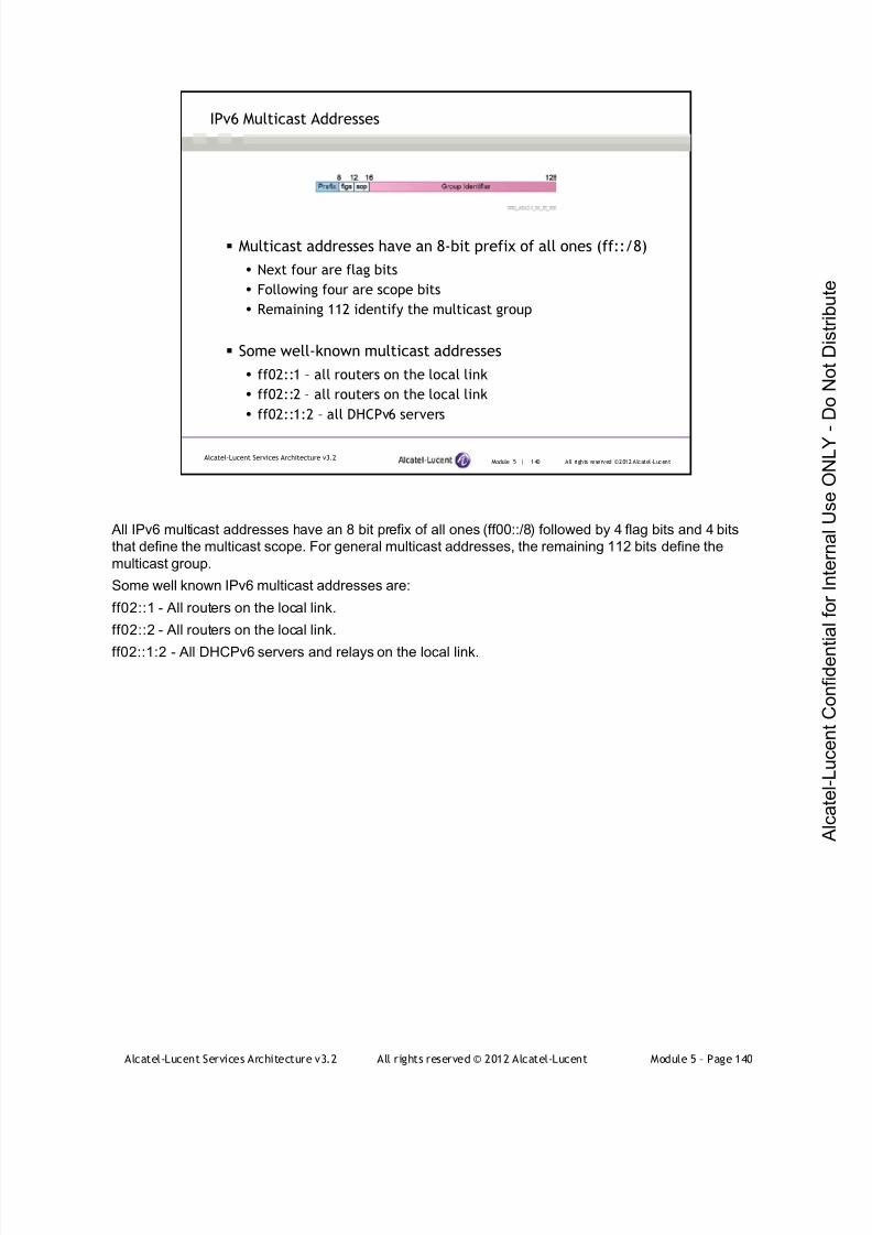
7/21/2019 Services Architecture v3.2 Student Guide Download
http://slidepdf.com/reader/full/services-architecture-v32-student-guide-download 416/429
Alcatel-Lucent Services Architecture v3.2 All rights reserved © 2012 Alcatel-Lucent Module 5 – Page 140
Module 5 | 140 All rights reserved ©2012 Alcatel-LucentAlcatel-Lucent Services Architecture v3.2
IPv6 Multicast Addresses
Multicast addresses have an 8-bit prefix of all ones (ff::/8)
Next four are flag bits
Following four are scope bits
Remaining 112 identify the multicast group
Some well-known multicast addresses
ff02::1 – all routers on the local link
ff02::2 – all routers on the local link
ff02::1:2 – all DHCPv6 servers
All IPv6 multicast addresses have an 8 bit prefix of all ones (ff00::/8) followed by 4 flag bits and 4 bits
that define the multicast scope. For general multicast addresses, the remaining 112 bits define the
multicast group.
Some well known IPv6 multicast addresses are:
ff02::1 - All routers on the local link.
ff02::2 - All routers on the local link.
ff02::1:2 - All DHCPv6 servers and relays on the local link.

7/21/2019 Services Architecture v3.2 Student Guide Download
http://slidepdf.com/reader/full/services-architecture-v32-student-guide-download 417/429
Alcatel-Lucent Services Architecture v3.2 All rights reserved © 2012 Alcatel-Lucent Module 5 – Page 141
Module 5 | 141 All rights reserved ©2012 Alcatel-LucentAlcatel-Lucent Services Architecture v3.2
IPv6 Solicited-Node Multicast
Replaces the broadcast address from IPv4
In 112-bit field, 79 zeroes followed by 9 ones, then 24 bitsfrom the unicast address
Last 24 bits are last 24 bits of unicast address being solicited
03-03-xx-xx-xx-xx reserved by IEEE for IPv6 multicast
MAC multicast address formed from last 32 bits of IPv6multicast address
IPv6 also defines a group of multicast addresses called ‘solicited-node multicast.’ The sixteen bits of the
prefix, flags and scope are followed by 79 zeroes and 9 ones. The remaining 24 bits are taken from the
last 24 bits of the unicast address (or addresses) that is being solicited. If the destination router has the
address 2001:db8::30a:216:4dff:fe13:5cae, then the solicited-node multicast address becomes
ff02::1:ff13:5cae.
The IEEE provides the range of multicast addresses of 03-03-xx-xx-xx-xx for IPv6, where the xx-xx-xx-
xx string is the 32 low-order bits of the multicast IP address. Each IPv6 node on Ethernet automatically
joins the multicast groups corresponding to their solicited-node address and the all-routers address.Thus, the host in this example will receive the Ethernet multicast groups:
03-03-ff-13-5c-ae and
03-03-00-00-00-01
The use of solicited-node multicast for host address resolution is described in the ICMPv6 section.

7/21/2019 Services Architecture v3.2 Student Guide Download
http://slidepdf.com/reader/full/services-architecture-v32-student-guide-download 418/429
Alcatel-Lucent Services Architecture v3.2 All rights reserved © 2012 Alcatel-Lucent Module 5 – Page 142
Module 5 | 142 All rights reserved ©2012 Alcatel-LucentAlcatel-Lucent Services Architecture v3.2
Anycast Addresses
Anycast address is a special use of a unicast address
Any unicast address can be used for anycast
Packets with an anycast address are routed to closest deviceassigned the address
Useful for redundant services such as DNS
RFC 2526 reserves the highest 128 addresses on every subnetas anycast addresses
Must not be assigned as unicast addresses
Anycast addresses are used in limited situations in IPv4, but IPv6 formally incorporates the concept of
an anycast addresses. Think of an anycast address as a virtual unicast address shared by multiple
hosts. An IPv6 packet sent to an anycast address is routed to the nearest reachable host assigned the
anycast address. This is a useful mechanism for providing a redundant service, such as a DNS server.
An anycast address can be formed from any unicast address. In addition, RFC 2526 defines a range of
anycast addresses to be reserved on every subnet for well-known services. This range is the highest
128 interface addresses on the subnet. These addresses must never be assigned as unicast addresses.
It’s similar to the concept in IPv4 of reserving the highest address as the broadcast address on a subnet,except that a range of 128 addresses (from 0 to 127) is reserved for anycast in IPv6. To date, only one
address in this range has been assigned - the value 126, for Mobile IPv6 Home Agents.
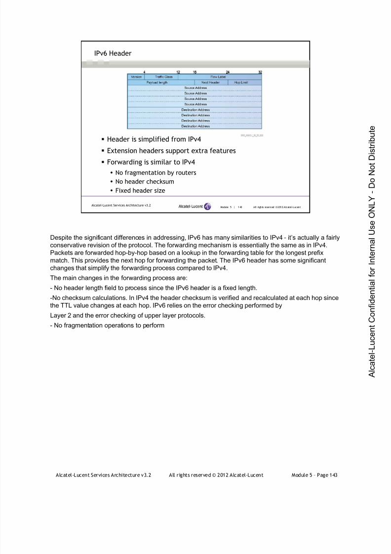
7/21/2019 Services Architecture v3.2 Student Guide Download
http://slidepdf.com/reader/full/services-architecture-v32-student-guide-download 419/429
Alcatel-Lucent Services Architecture v3.2 All rights reserved © 2012 Alcatel-Lucent Module 5 – Page 143
Module 5 | 143 All rights reserved ©2012 Alcatel-LucentAlcatel-Lucent Services Architecture v3.2
IPv6 Header
Header is simplified from IPv4
Extension headers support extra features
Forwarding is similar to IPv4
No fragmentation by routers
No header checksum
Fixed header size
Despite the significant differences in addressing, IPv6 has many similarities to IPv4 - it’s actually a fairly
conservative revision of the protocol. The forwarding mechanism is essentially the same as in IPv4.
Packets are forwarded hop-by-hop based on a lookup in the forwarding table for the longest prefix
match. This provides the next hop for forwarding the packet. The IPv6 header has some significant
changes that simplify the forwarding process compared to IPv4.
The main changes in the forwarding process are:
- No header length field to process since the IPv6 header is a fixed length.-No checksum calculations. In IPv4 the header checksum is verified and recalculated at each hop since
the TTL value changes at each hop. IPv6 relies on the error checking performed by
Layer 2 and the error checking of upper layer protocols.
- No fragmentation operations to perform
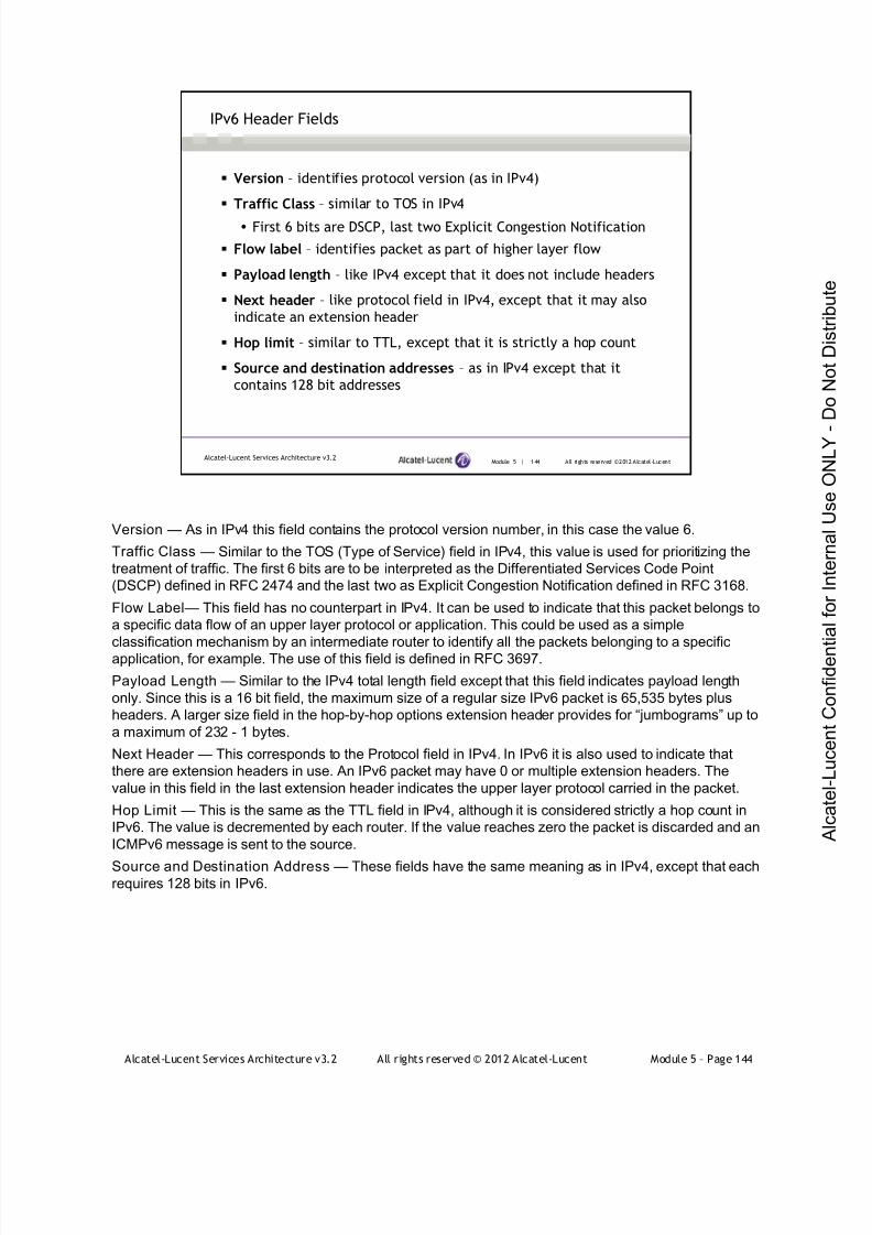
7/21/2019 Services Architecture v3.2 Student Guide Download
http://slidepdf.com/reader/full/services-architecture-v32-student-guide-download 420/429
Alcatel-Lucent Services Architecture v3.2 All rights reserved © 2012 Alcatel-Lucent Module 5 – Page 144
Module 5 | 144 All rights reserved ©2012 Alcatel-LucentAlcatel-Lucent Services Architecture v3.2
IPv6 Header Fields
Version – identifies protocol version (as in IPv4)
Traffic Class – similar to TOS in IPv4
First 6 bits are DSCP, last two Explicit Congestion Notification
Flow label – identifies packet as part of higher layer flow
Payload length – like IPv4 except that it does not include headers
Next header – like protocol field in IPv4, except that it may also
indicate an extension header
Hop limit – similar to TTL, except that it is strictly a hop count
Source and destination addresses – as in IPv4 except that it
contains 128 bit addresses
Version — As in IPv4 this field contains the protocol version number, in this case the value 6.
Traffic Class — Similar to the TOS (Type of Service) field in IPv4, this value is used for prioritizing the
treatment of traffic. The first 6 bits are to be interpreted as the Differentiated Services Code Point
(DSCP) defined in RFC 2474 and the last two as Explicit Congestion Notification defined in RFC 3168.
Flow Label — This field has no counterpart in IPv4. It can be used to indicate that this packet belongs to
a specific data flow of an upper layer protocol or application. This could be used as a simple
classification mechanism by an intermediate router to identify all the packets belonging to a specificapplication, for example. The use of this field is defined in RFC 3697.
Payload Length — Similar to the IPv4 total length field except that this field indicates payload length
only. Since this is a 16 bit field, the maximum size of a regular size IPv6 packet is 65,535 bytes plus
headers. A larger size field in the hop-by-hop options extension header provides for “jumbograms” up to
a maximum of 232 - 1 bytes.
Next Header — This corresponds to the Protocol field in IPv4. In IPv6 it is also used to indicate that
there are extension headers in use. An IPv6 packet may have 0 or multiple extension headers. The
value in this field in the last extension header indicates the upper layer protocol carried in the packet.
Hop Limit — This is the same as the TTL field in IPv4, although it is considered strictly a hop count in
IPv6. The value is decremented by each router. If the value reaches zero the packet is discarded and an
ICMPv6 message is sent to the source.
Source and Destination Address — These fields have the same meaning as in IPv4, except that eachrequires 128 bits in IPv6.

7/21/2019 Services Architecture v3.2 Student Guide Download
http://slidepdf.com/reader/full/services-architecture-v32-student-guide-download 421/429
Alcatel-Lucent Services Architecture v3.2 All rights reserved © 2012 Alcatel-Lucent Module 5 – Page 145
Module 5 | 145 All rights reserved ©2012 Alcatel-LucentAlcatel-Lucent Services Architecture v3.2
IPv6 Next Header Field
Value Description
0 IPv6 Hop-by-hop options
6 Upper layer protocol – TCP
17 Upper layer protocol – UDP
41 IPv6 Encapsulation header (tunneling)
43 Routing extension header
44 Fragment extension header
50 Encapsulating Security Payload (ESP)
51 Authentication Header (AH)
58 ICMPv6
59 IPv6 No next header
60 Destination options
In general, only the IPv6 header is used by intermediate routers for forwarding, and the extension
headers are only processed at the destination. The exception is the hop-by-hop options header that
must be processed by each intermediate router. Therefore, if it exists, it must be the first extension
header after the IPv6 header. The extension headers described below must be supported by all IPv6
routers.
Hop-by-hop options — These are a grouping of options that must be processed by intermediate
routers. These include the option for jumbograms (RFC 2675) and the Router Alert option (RFC 2711).
Routing extension header — This provides the ability for source routing. RFC 2460 defines a Type 0
routing header (RH0) for loose source, but this was deprecated in RFC 5095 because of security
concerns. Mobility support in IPv6 (RFC 3775) defines a Type 2 routing header (RH2).
Fragment extension header — IPv6 routers do not fragment IPv6 packets, but the fragment extension
header allows the source router to fragment packets in case the payload supplied by the upper layer
protocol is too large for the link or path MTU. This should not be a common occurrence.
ESP header — The ESP header (RFC 2402) is an IPsec header that provides security for IPv6 and
IPv4. ESP provides authentication, data integrity and data confidentiality for all fields after the ESP
header, but not for the IPv6 header.
AH header — The AH header (RFC 2406) is an IPsec header that provides authentication for IPv6 and
IPv4. AH provides authentication and data integrity services for the entire packet, except for the fields of
the header that might change in transit (Traffic Class, Flow Label and Hop Limit).Destination options — The destination extension header defines options that are to be examined only
by the destination router. Mobility support in IPv6 (RFC 3775) defines a Type 201 destination option for
carrying the Home Address of a mobile router.
Except for the hop-by-hop options header, the extension headers have no impact of the forwarding of
IPv6 packets and are not discussed any further in this course.
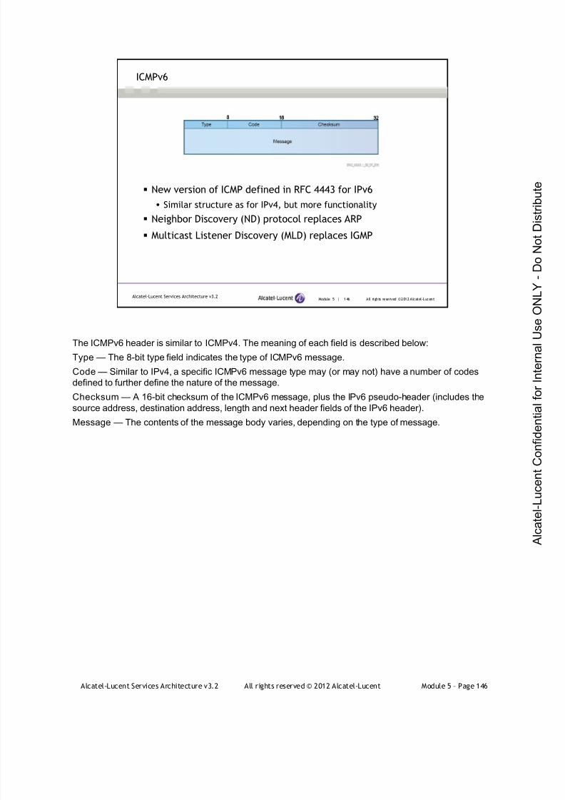
7/21/2019 Services Architecture v3.2 Student Guide Download
http://slidepdf.com/reader/full/services-architecture-v32-student-guide-download 422/429
Alcatel-Lucent Services Architecture v3.2 All rights reserved © 2012 Alcatel-Lucent Module 5 – Page 146
Module 5 | 146 All rights reserved ©2012 Alcatel-LucentAlcatel-Lucent Services Architecture v3.2
ICMPv6
New version of ICMP defined in RFC 4443 for IPv6
Similar structure as for IPv4, but more functionality
Neighbor Discovery (ND) protocol replaces ARP
Multicast Listener Discovery (MLD) replaces IGMP
The ICMPv6 header is similar to ICMPv4. The meaning of each field is described below:
Type — The 8-bit type field indicates the type of ICMPv6 message.
Code — Similar to IPv4, a specific ICMPv6 message type may (or may not) have a number of codes
defined to further define the nature of the message.
Checksum — A 16-bit checksum of the ICMPv6 message, plus the IPv6 pseudo-header (includes the
source address, destination address, length and next header fields of the IPv6 header).
Message — The contents of the message body varies, depending on the type of message.
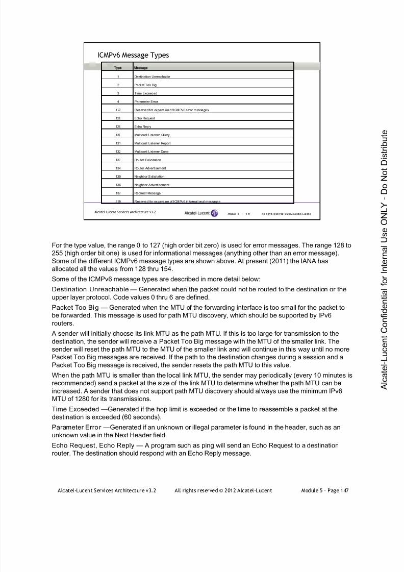
7/21/2019 Services Architecture v3.2 Student Guide Download
http://slidepdf.com/reader/full/services-architecture-v32-student-guide-download 423/429
Alcatel-Lucent Services Architecture v3.2 All rights reserved © 2012 Alcatel-Lucent Module 5 – Page 147
Module 5 | 147 All rights reserved ©2012 Alcatel-LucentAlcatel-Lucent Services Architecture v3.2
ICMPv6 Message Types
ype essage
1 Destination Unreachable
2 Packet Too Big
3 Time Exceeded
4 Parameter Error
127 Reserved for expansion of ICMPv6 error messages
128 Echo Request
129 Echo Reply
130 Multicast Listener Query
131 Multicast Listener Report
132 Multicast Listener Done
133 Router Solicitation
134 Router Advertisement
135 Neighbor S olicitation
136 Neighbor Advert isement
137 Redirect Message
255 Reserved for expansion of ICMPv6 informational messages
For the type value, the range 0 to 127 (high order bit zero) is used for error messages. The range 128 to
255 (high order bit one) is used for informational messages (anything other than an error message).
Some of the different ICMPv6 message types are shown above. At present (2011) the IANA has
allocated all the values from 128 thru 154.
Some of the ICMPv6 message types are described in more detail below:
Destination Unreachable — Generated when the packet could not be routed to the destination or the
upper layer protocol. Code values 0 thru 6 are defined.Packet Too Big — Generated when the MTU of the forwarding interface is too small for the packet to
be forwarded. This message is used for path MTU discovery, which should be supported by IPv6
routers.
A sender will initially choose its link MTU as the path MTU. If this is too large for transmission to the
destination, the sender will receive a Packet Too Big message with the MTU of the smaller link. The
sender will reset the path MTU to the MTU of the smaller link and will continue in this way until no more
Packet Too Big messages are received. If the path to the destination changes during a session and a
Packet Too Big message is received, the sender resets the path MTU to this value.
When the path MTU is smaller than the local link MTU, the sender may periodically (every 10 minutes is
recommended) send a packet at the size of the link MTU to determine whether the path MTU can be
increased. A sender that does not support path MTU discovery should always use the minimum IPv6
MTU of 1280 for its transmissions.Time Exceeded —Generated if the hop limit is exceeded or the time to reassemble a packet at the
destination is exceeded (60 seconds).
Parameter Error —Generated if an unknown or illegal parameter is found in the header, such as an
unknown value in the Next Header field.
Echo Request, Echo Reply — A program such as ping will send an Echo Request to a destination
router. The destination should respond with an Echo Reply message.

7/21/2019 Services Architecture v3.2 Student Guide Download
http://slidepdf.com/reader/full/services-architecture-v32-student-guide-download 424/429
Alcatel-Lucent Services Architecture v3.2 All rights reserved © 2012 Alcatel-Lucent Module 5 – Page 148
Module 5 | 148 All rights reserved ©2012 Alcatel-LucentAlcatel-Lucent Services Architecture v3.2
Neighbor Discovery Functions
Router discovery – find routers on a link
Prefix discovery – find address prefixes on a link
Parameter discovery – find link parameters
Address autoconfiguration – automatically configure an address
Address resolution – resolve IPv6 address to a link layer address
Next-hop determination – find next-hop address for a destination
Neighbor unreachability – determine that the neighbor is not
reachable
Duplicate address detection – identify duplicate addresses on a link
Redirect – inform host of a better next hop
The neighbor discovery (ND) protocol for IPv6 (RFC 4861) provides the capabilities handled in IPv4 by
ARP, router discovery and router redirect and quite a few additional capabilities as well. The functions
handled by ND are:
Router discovery — Find routers on a link.
Prefix discovery — Find the address prefixes for a link.
Parameter discovery — Find link parameters such as MTU or hop Limit.
Address autoconfigurat ion —Mechanism that allows an interface to configure its own address (defined
in RFC 4862).
Address resolut ion — Resolve a destination IP address to a link layer address.
Next-hop determination — Map an IP address into the next-hop address that the packet should be
sent to.
Neighbor unreachability detection — Mechanism to determine that the neighbor is no longer
reachable. If this is the default router, the host can change its default to another router.
Duplicate address detection — Mechanism to identify duplicate addresses on the link.
Redirect — Allow a router to inform a host of a better next hop to a destination.
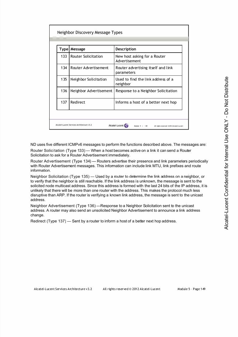
7/21/2019 Services Architecture v3.2 Student Guide Download
http://slidepdf.com/reader/full/services-architecture-v32-student-guide-download 425/429
Alcatel-Lucent Services Architecture v3.2 All rights reserved © 2012 Alcatel-Lucent Module 5 – Page 149
Module 5 | 149 All rights reserved ©2012 Alcatel-LucentAlcatel-Lucent Services Architecture v3.2
Neighbor Discovery Message Types
Type Message Description
133 Router Solicitation New host asking for a Router
Advertisement
134 Router Advertisement Router advertising itself and link
parameters
135 Neighbor Solicitation Used to find the link address of a
neighbor
136 Neighbor Advertisement Response to a Neighbor Solicitation
137 Redirect Informs a host of a better next hop
ND uses five different ICMPv6 messages to perform the functions described above. The messages are:
Router Solici tation (Type 133) — When a host becomes active on a link it can send a Router
Solicitation to ask for a Router Advertisement immediately.
Router Advertisement (Type 134) — Routers advertise their presence and link parameters periodically
with Router Advertisement messages. This information can include link MTU, link prefixes and route
information.
Neighbor Solicitation (Type 135) — Used by a router to determine the link address on a neighbor, orto verify that the neighbor is still reachable. If the link address is unknown, the message is sent to the
solicited node multicast address. Since this address is formed with the last 24 bits of the IP address, it is
unlikely that there will be more than one router with the address. This makes the protocol much less
disruptive than ARP. If the router is verifying a known link address, the message is sent to the unicast
address.
Neighbor Advertisement (Type 136) —Response to a Neighbor Solicitation sent to the unicast
address. A router may also send an unsolicited Neighbor Advertisement to announce a link address
change.
Redirect (Type 137) — Sent by a router to inform a host of a better next hop address.

7/21/2019 Services Architecture v3.2 Student Guide Download
http://slidepdf.com/reader/full/services-architecture-v32-student-guide-download 426/429
Alcatel-Lucent Services Architecture v3.2 All rights reserved © 2012 Alcatel-Lucent Module 5 – Page 150
Module 5 | 150 All rights reserved ©2012 Alcatel-LucentAlcatel-Lucent Services Architecture v3.2
MAC Address Discovery
Router sends Neighbor Solicitation to solicited-node multicast
address (03-03-ff-0e-93-31)
Neighbor responds with Neighbor Advertisement to unicast address
Neighbor Discovery replaces the ARP protocol in IPv4. A device that wants to resolve an IPv6 address
to a MAC address sends a Neighbor Solicitation message containing the IPv6 address. This message is
sent to the solicited node multicast address formed from the desired unicast address. The neighbor that
has this unicast address is likely the only one listening to this multicast group. It responds with a
Neighbor Advertisement message containing its MAC address. ND is more efficient than ARP since
other hosts on the network do not have to process a broadcast message.
The flags in the Neighbor Advertisement message have the following meaning:
Router — The advertisement message was sent by a router.
Solicited —The advertisement was sent in response to a Neighbor Solicitation message.
Override —The advertisement should override an existing cache entry.

7/21/2019 Services Architecture v3.2 Student Guide Download
http://slidepdf.com/reader/full/services-architecture-v32-student-guide-download 427/429
Alcatel-Lucent Services Architecture v3.2 All rights reserved © 2012 Alcatel-Lucent Module 5 – Page 151
Module 5 | 151 All rights reserved ©2012 Alcatel-LucentAlcatel-Lucent Services Architecture v3.2
Configuring IPv6 Interfaces
Link-local address automatically created from MAC address
Global routing addresses can be assigned as needed
Router must have chassis-mode ‘c’ or higher
*A: R1# configure system chassis-mode c force
*A: R1# configure router
*A: R1>conf i g>r out er# interface "toR2" ipv6
*A: R1>conf i g>r outer >i f >i pv6# exit
*A: R1>conf i g>r out er# interface "toR3" ipv6
*A: R1>conf i g>r out er>i f >i pv6# exit
*A: R1>conf i g>r out er# interface "system" ipv6
*A: R1>conf i g>r out er>i f >i pv6# address 2001:db8:1:100::1/128
*A: R1>conf i g>r out er>i f >i pv6# exit
Configuring IPv6 interfaces and routing for IPv6 is very similar to configuration of IPv4. The most
obvious difference is the use of IPv6 addresses. IPv6 and IPv4 can be configured in parallel on the
same network.
In order to use IPv6 on the Alcatel-Lucent 7750 SR, you must first enable chassis mode “c” or higher.
IPv6 is only supported on IOM2s or newer. As soon as we enable IPv6 on the interface, a link local
address is automatically assigned based on the modified EUI-64 address. If it’s not necessary to route to
the interfaces, we don’t need to assign them global routing addresses - we can simply use the link local
addresses.
In this example, the enterprise has been allocated a prefix from their service provider, 2001:db8:1::/48.
The enterprise decides to subnet the prefix using the first 8 bits to identify a specific location and the
second 8 bits to identify subnets at that location. The router in this example is at location 01. System
interfaces are addressed using subnet 00 at all locations. The system address for this router is thus
2001:db8:1:100::1/128, which is assigned to the system interface.
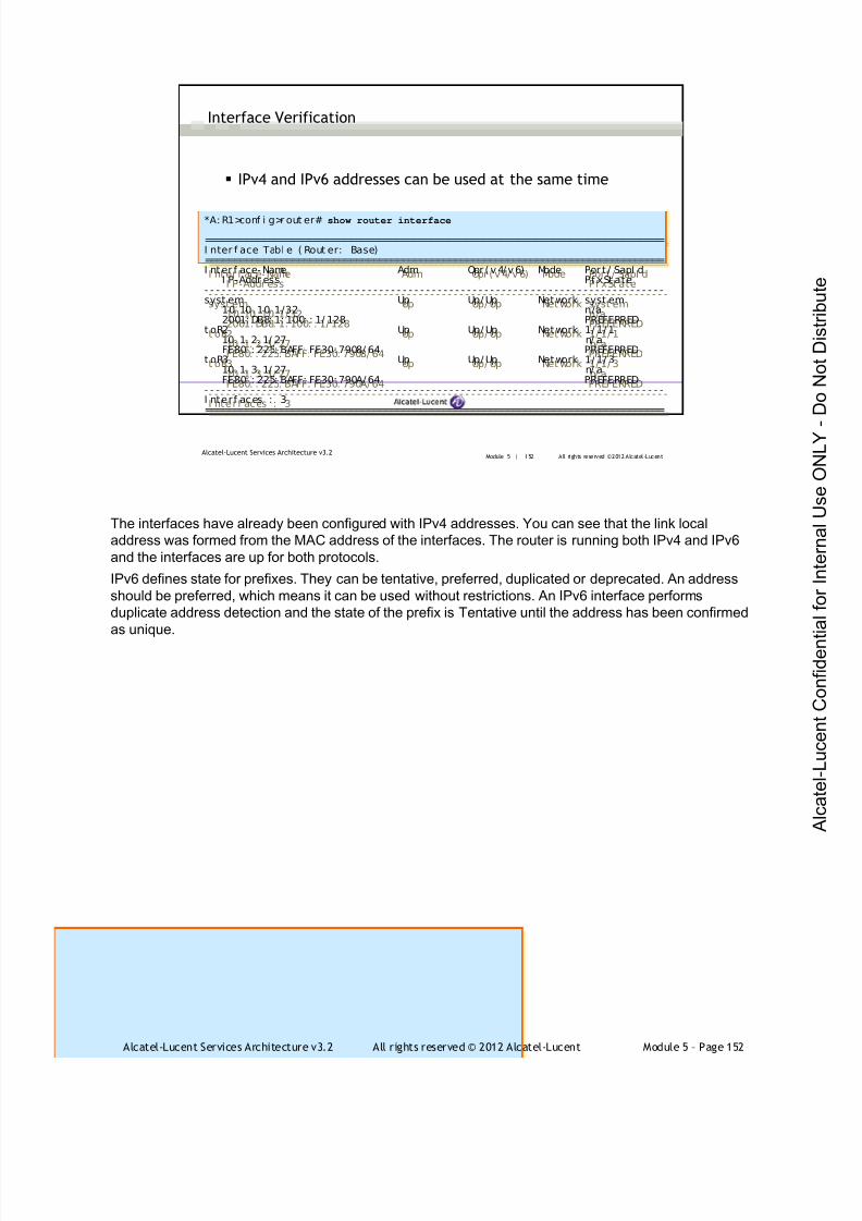
7/21/2019 Services Architecture v3.2 Student Guide Download
http://slidepdf.com/reader/full/services-architecture-v32-student-guide-download 428/429
Alcatel-Lucent Services Architecture v3.2 All rights reserved © 2012 Alcatel-Lucent Module 5 – Page 152
Module 5 | 152 All rights reserved ©2012 Alcatel-LucentAlcatel-Lucent Services Architecture v3.2
Interface Verification
IPv4 and IPv6 addresses can be used at the same time
*A: R1>conf i g>r out er# show router interface
===============================================================================I nter f ace Tabl e ( Rout er: Base)===============================================================================I nter f ace- Name Adm Opr (v4/ v6) Mode Por t / SapI d
I P-Addr ess Pf xSt ate- - - - - - - - - - - - - - - - - - - - - - - - - - - - - - - - - - - - - - - - - - - - - - - - - - - - - - - - - - - - - - - - - - - - - - - - - - - - - - -syst em Up Up/ Up Network syst em
10. 10. 10. 1/32 n/a2001: DB8: 1: 100: : 1/ 128 PREFERRED
t oR2 Up Up/ Up Network 1/ 1/ 110. 1. 2. 1/ 27 n/ aFE80: : 225: BAFF: FE30: 7908/ 64 PREFERRED
t oR3 Up Up/ Up Network 1/ 1/ 310. 1. 3. 1/ 27 n/ aFE80: : 225: BAFF: FE30: 790A/ 64 PREFERRED
- - - - - - - - - - - - - - - - - - - - - - - - - - - - - - - - - - - - - - - - - - - - - - - - - - - - - - - - - - - - - - - - - - - - - - - - - - - - - - -I nterf aces : 3===============================================================================
The interfaces have already been configured with IPv4 addresses. You can see that the link local
address was formed from the MAC address of the interfaces. The router is running both IPv4 and IPv6
and the interfaces are up for both protocols.
IPv6 defines state for prefixes. They can be tentative, preferred, duplicated or deprecated. An address
should be preferred, which means it can be used without restrictions. An IPv6 interface performs
duplicate address detection and the state of the prefix is Tentative until the address has been confirmed
as unique.

7/21/2019 Services Architecture v3.2 Student Guide Download
http://slidepdf.com/reader/full/services-architecture-v32-student-guide-download 429/429
Module 5 | 153 All rights reserved ©2012 Alcatel-LucentAlcatel-Lucent Services Architecture v3.2
Interface Verification (continued)
Link-local addresses never appear in the route table
Router can route both IPv4 and IPv6
*A: R1>conf i g>r out er# show router route-table ipv6
===============================================================================I Pv6 Rout e Tabl e (Router : Base)===============================================================================Dest Pref i x Type Prot o Age Pref
Next Hop[ I nterf ace Name] Metr i c- - - - - - - - - - - - - - - - - - - - - - - - - - - - - - - - - - - - - - - - - - - - - - - - - - - - - - - - - - - - - - - - - - - - - - - - - - - - - - -2001: DB8: 1: 100: : 1/ 128 Local Local 00h08m56s 0
system 0- - - - - - - - - - - - - - - - - - - - - - - - - - - - - - - - - - - - - - - - - - - - - - - - - - - - - - - - - - - - - - - - - - - - - - - - - - - - - - -No. of Rout es: 1===============================================================================*A: R1>conf i g>r out er#
*A: R1>conf i g>r out er# show router route-table ipv6
===============================================================================I Pv6 Rout e Tabl e (Router : Base)===============================================================================Dest Pref i x Type Prot o Age Pref
Next Hop[ I nt erf ace Name] Metr i c- - - - - - - - - - - - - - - - - - - - - - - - - - - - - - - - - - - - - - - - - - - - - - - - - - - - - - - - - - - - - - - - - - - - - - - - - - - - - - -2001: DB8: 1: 100: : 1/ 128 Local Local 00h08m56s 0
system 0- - - - - - - - - - - - - - - - - - - - - - - - - - - - - - - - - - - - - - - - - - - - - - - - - - - - - - - - - - - - - - - - - - - - - - - - - - - - - - -No. of Rout es: 1===============================================================================*A: R1>conf i g>r out er#
The interfaces have already been configured with IPv4 addresses. You can see that the link local
address was formed from the MAC address of the interfaces. The router is running both IPv4 and IPv6
and the interfaces are up for both protocols.