service-modul sm01 mgc microdrive · service-modul sm01 . mgc microdrive . ... the zip-file...
TRANSCRIPT
Technical Manual
Service-Modul SM01 MGC MicroDrive
This technical manual is a supplement to the operating instructions "Barrier MHTMTM MicroDrive" (5815,5001) and describes the service module.
Before using the service module, read this manual and the operating instructions "Barrier MHTMTM MicroDrive" carefully!
Doc-ID: 5815,0002EN
Version: 04

Web: www.MagneticGateOpeners.com Phone: (800) 878-7829Fax: (330) 650-9004Email: [email protected]
2 5815,0002EN / Version 04

Service-Modul SM01 MGC MicroDrive
Contents
5815,0002EN / Version 04 3
Contents
1 General....................................................................................5 1.1 Pictogram explanation ...................................................5 1.2 Scope of delivery ...........................................................6
2 Safety ......................................................................................7 2.1 Intended use ..................................................................7 2.2 Requirements to the specialists.....................................7
3 Technical data ........................................................................8 3.1 Supported operating systems........................................8 3.2 Environmental conditions...............................................8
4 Design and function...............................................................8 4.1 Design............................................................................8 4.2 Function .........................................................................9 4.3 Status indicators (LEDs) ................................................9
5 Perform update.....................................................................10 5.1 Required steps.............................................................10 5.2 ZIP file structure...........................................................11 5.3 Connect service module to the PC ..............................11 5.4 Copy files onto the service module
and select language for the service module ................12 5.5 Installing firmware on the service module ...................13 5.6 Write down current parameter settings
and connect service module to control unit .................13 5.7 Install new firmware on the control unit
and the plug-in modules ..............................................16 5.8 Assume Firmware factory settings for the
control unit and enter the noted parameter settings....17 5.9 MicroDrive Toll HighSpeed –
installing new firmware on the motor ...........................17
6 Operation ..............................................................................19 6.1 Setting service mode, opening barrier.........................19 6.2 Logger functions ..........................................................19
6.2.1 Start and stop logger ....................................19 6.2.2 Call log files ..................................................21
6.3 Copying parameterisation from one barrier to other barriers – Copy paste function.....................................21 6.3.1 Copy .............................................................22 6.3.2 Configurations file "CC.dat"..........................23
6.4 Install parameter file ....................................................23 6.5 Manage and inspect log file .........................................25
6.5.1 Read error storage .......................................26
Index..............................................................................................27

Service-Modul SM01 MGC MicroDrive
4 5815,0002EN / Version 04
Service-Modul SM01 MGC MicroDrive
Contents
1 General
1.1 Pictogram explanation
Warning notes Warning notes are characterised by pictograms in these operating instructions. The warning notes are prelude by signal words expressing the scale of the hazard.
It is absolutely essential to observe the notes and to proceed with caution in order to prevent accidents as well as bodily injuries and property damage.
WARNING!
WARNING!
… … points to a potentially dangerous situation, which can lead to death or severe injuries if it is not avoided.
Hints and recommendations
NOTE!
… highlights useful hints and recommendations as well as information for an efficient and trouble-free operation.
5815,0002EN / Version 04 5
Service-Modul SM01 MGC MicroDrive
Contents
1.2 Scope of delivery
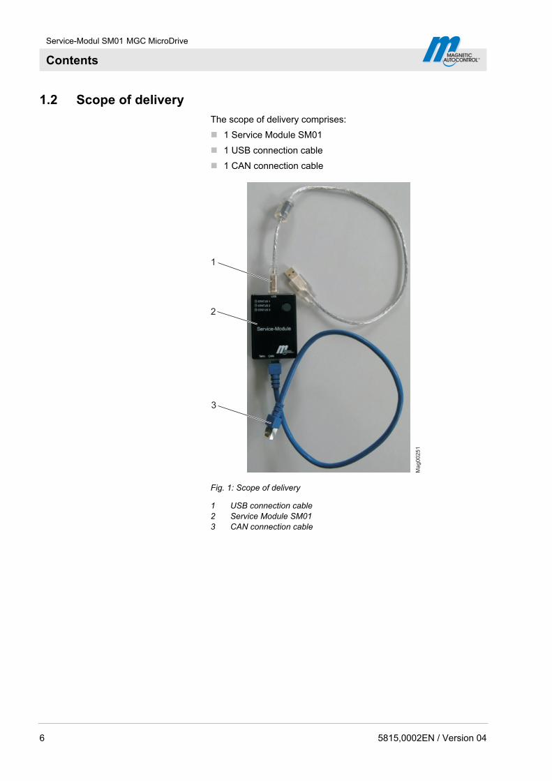
The scope of delivery comprises:
1 Service Module SM01
1 USB connection cable
1 CAN connection cable
Mag00251
1
2
3
Fig. 1: Scope of delivery
1 USB connection cable 2 Service Module SM01 3 CAN connection cable
6 5815,0002EN / Version 04
Service-Modul SM01 MGC MicroDrive
Contents
2 Safety
2.1 Intended use
The service module SM01 is solely meant to install software on control units of the series MGC, MGC-Pro and their plug-in modules.
Any types of claims due to damage arising from improper use are excluded. The operator alone shall be responsible for any damage arising from improper use.
2.2 Requirements to the specialists
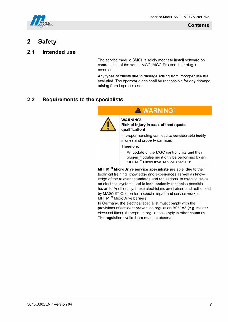
WARNING!
WARNING! Risk of injury in case of inadequate qualification!
Improper handling can lead to considerable bodily injuries and property damage.
Therefore:
– An update of the MGC control units and their plug-in modules must only be performed by an MHTMTM MicroDrive service specialist.
MHTMTM MicroDrive service specialists are able, due to their technical training, knowledge and experiences as well as know-ledge of the relevant standards and regulations, to execute tasks on electrical systems and to independently recognise possible hazards. Additionally, these electricians are trained and authorised by MAGNETIC to perform special repair and service work at MHTMTM MicroDrive barriers. In Germany, the electrical specialist must comply with the provisions of accident prevention regulation BGV A3 (e.g. master electrical fitter). Appropriate regulations apply in other countries. The regulations valid there must be observed.
5815,0002EN / Version 04 7
Service-Modul SM01 MGC MicroDrive
Contents
3 Technical data
3.1 Supported operating systems
The service module SM01 has been tested with the following operating systems:
Windows XP
Windows Vista
Windows 7
3.2 Environmental conditions
Unit Value
Ambient temperature range °C –20 to +50
Table 1: Technical data
4 Design and function
4.1 Design
24
3
1M
ag
00
25
5
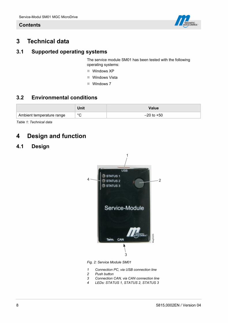
Fig. 2: Service Module SM01
1 Connection PC, via USB connection line 2 Push button 3 Connection CAN, via CAN connection line 4 LEDs: STATUS 1, STATUS 2, STATUS 3
8 5815,0002EN / Version 04
Service-Modul SM01 MGC MicroDrive
Contents
5815,0002EN / Version 04 9
4.2 Function
The service module SM01 can be used to install software easily and comfortably on control units of the series MGC, MGC-Pro and their plug-on modules.
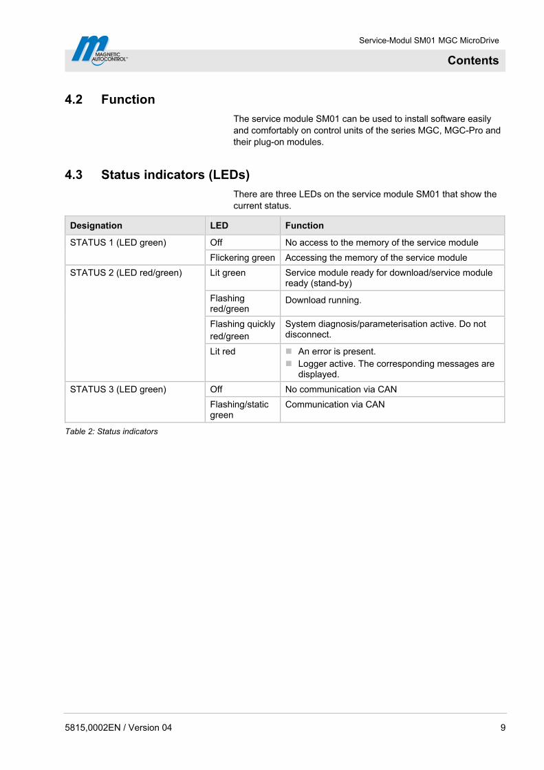
4.3 Status indicators (LEDs)
There are three LEDs on the service module SM01 that show the current status.
Designation LED Function
Off No access to the memory of the service module STATUS 1 (LED green)
Flickering green Accessing the memory of the service module
Lit green Service module ready for download/service module ready (stand-by)
Flashing red/green
Download running.
Flashing quicklyred/green
System diagnosis/parameterisation active. Do not disconnect.
STATUS 2 (LED red/green)
Lit red An error is present. Logger active. The corresponding messages are
displayed.
Off No communication via CAN STATUS 3 (LED green)
Flashing/static green
Communication via CAN
Table 2: Status indicators
Service-Modul SM01 MGC MicroDrive
Contents
10 5815,0002EN / Version 04
5 Perform update
5.1 Required steps
The service module SM01 is delivered with up-to-date files:
If a newer software is available, the required files are sent by email as a ZIP file.
Connect service module to the PC. See page 11, chapter 5.3.
Copy files onto the service module and select language for the service module. See page 12, chapter 5.4.
If required, install firmware for the service module on the service module. See page 13, chapter 5.5.
Write down current parameter settings and connect service module to control unit. See page 13, chapter 5.6.
Install new firmware on the control unit and the plug-in modules. See page 16, chapter 5.7.
Assume firmware works settings for the control unit and enter the noted parameter settings. See page 19, chapter 5.8.

Service-Modul SM01 MGC MicroDrive
Contents
5.2 ZIP file structure
Do not change files
NOTE!
The configuration file "cls.ini" and the file names must not be changed. If the files are changed, no update can be performed.
ZIP-file "SMP-MGC-xxx_xx-xxx" The ZIP-file "SMP-MGC-xxx_xx-xxx" contains the following files:
Configurations file: "cls.ini"
Application files for control unit and plug-in modules "*.bin"
ZIP-file "49153005_SM01-Firmware" – update.hex
You will receive the ZIP-file "49153005_SM01-Firmware" if you have to perform an update for the service module SM 01. The ZIP-file "49153005_SM01-Firmware" contains the firmware file "update.hex" in the following languages:
DA: Danish/English
DE: German/English
ES: Spanish/English
ET: Estonian/English
FI: Finnish/English
FR: French/English
IT: Italian/English
NL: Dutch/English
NO: Norwegian/English
PT: Portuguese/English
SV: Swedish/English
5.3 Connect service module to the PC
The new files for the control unit MGC and the associated plug-in modules are located on a PC.
1. Connect the service module to the PC via the included USB connection cable.
2. Wait for some minutes if required. If the service module is connected to the PC for the first time, the required drivers are automatically installed on the PC. This process may take up to three minutes.
3. The PC reports that new hardware has been installed.
4. The service module registers at the PC as a removable drive.
5815,0002EN / Version 04 11
Service-Modul SM01 MGC MicroDrive
Contents
5.4 Copy files onto the service module and select language for the service module
Back up old files
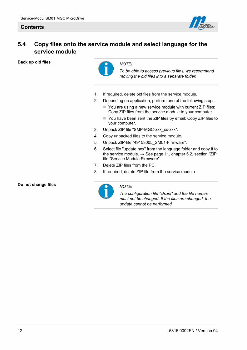
NOTE!
To be able to access previous files, we recommend moving the old files into a separate folder.
1. If required, delete old files from the service module.
2. Depending on application, perform one of the following steps:
You are using a new service module with current ZIP files: Copy ZIP files from the service module to your computer.
You have been sent the ZIP files by email: Copy ZIP files to your computer.
3. Unpack ZIP file "SMP-MGC-xxx_xx-xxx".
4. Copy unpacked files to the service module.
5. Unpack ZIP-file "49153005_SM01-Firmware".
6. Select file "update.hex" from the language folder and copy it to the service module. See page 11, chapter 5.2, section "ZIP file "Service Module Firmware".
7. Delete ZIP files from the PC.
8. If required, delete ZIP file from the service module.
Do not change files
NOTE!
The configuration file "cls.ini" and the file names must not be changed. If the files are changed, the update cannot be performed.
12 5815,0002EN / Version 04
Service-Modul SM01 MGC MicroDrive
Contents
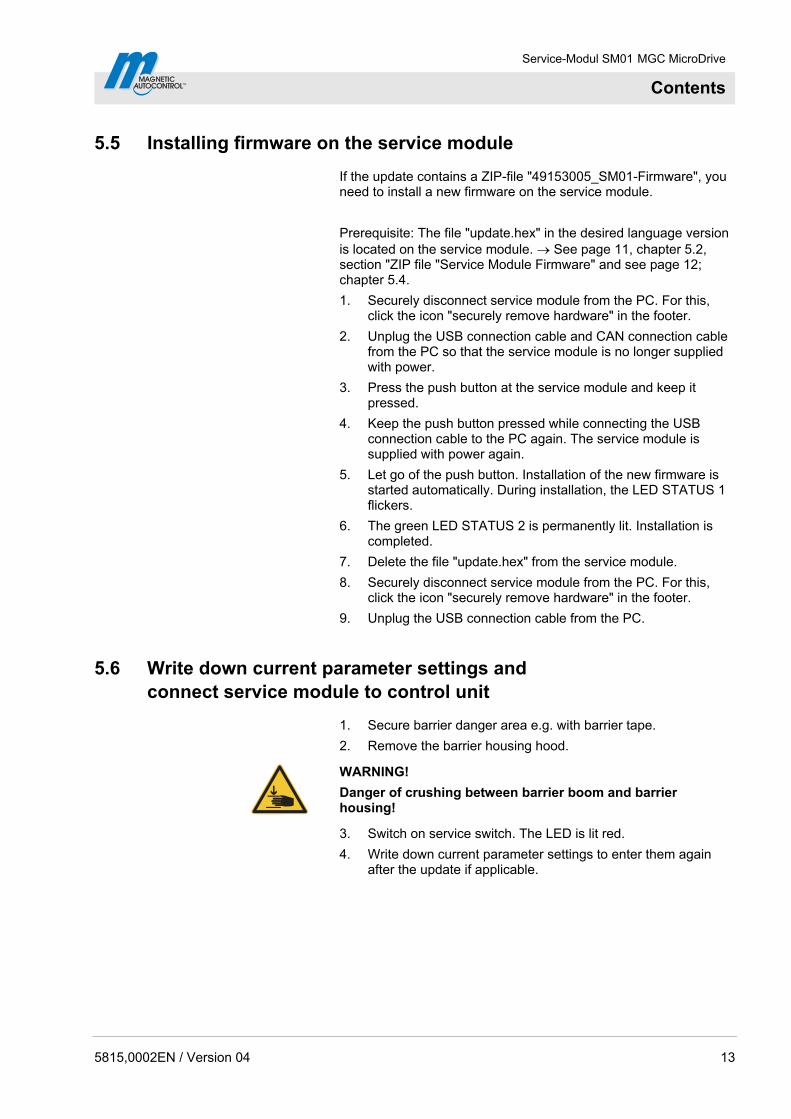
5.5 Installing firmware on the service module
If the update contains a ZIP-file "49153005_SM01-Firmware", you need to install a new firmware on the service module.
Prerequisite: The file "update.hex" in the desired language version is located on the service module. See page 11, chapter 5.2, section "ZIP file "Service Module Firmware" and see page 12; chapter 5.4.
1. Securely disconnect service module from the PC. For this, click the icon "securely remove hardware" in the footer.
2. Unplug the USB connection cable and CAN connection cable from the PC so that the service module is no longer supplied with power.
3. Press the push button at the service module and keep it pressed.
4. Keep the push button pressed while connecting the USB connection cable to the PC again. The service module is supplied with power again.
5. Let go of the push button. Installation of the new firmware is started automatically. During installation, the LED STATUS 1 flickers.
6. The green LED STATUS 2 is permanently lit. Installation is completed.
7. Delete the file "update.hex" from the service module.
8. Securely disconnect service module from the PC. For this, click the icon "securely remove hardware" in the footer.
9. Unplug the USB connection cable from the PC.
5.6 Write down current parameter settings and connect service module to control unit
1. Secure barrier danger area e.g. with barrier tape.
2. Remove the barrier housing hood.
WARNING!
Danger of crushing between barrier boom and barrier housing!
3. Switch on service switch. The LED is lit red.
4. Write down current parameter settings to enter them again after the update if applicable.
5815,0002EN / Version 04 13

Service-Modul SM01 MGC MicroDrive
Contents
NOTE!
If the EEPROM structure has changed between the new and previous firmware, the current settings are overwritten by the default values during an update. The control unit reports "0x6104 FW default values restored". In this case, you need to re-enter the user-specific settings.
5. Manually open the barrier with the middle left button at the control unit.
6. Unplug plug X11 for the light barrier connection from the control unit.
14 5815,0002EN / Version 04
NOTE!
For the barrier to remain securely opened, we recommend pulling the plugs X11 at the control unit.
7. Switch off the barrier's voltage supply.
8. Plug the included CAN connection cable into the RJ-45 socket at the service module.
9. Plug the CAN connection cable into the RJ-45 socket (X9) at the control unit MGC.
10. Switch on the barrier's voltage supply. The LED STATUS 2 is lit green. LED STATUS 3 flashes green or lit green.
Service-Modul SM01 MGC MicroDrive
Contents
Mag00253
1
2
3
4
5
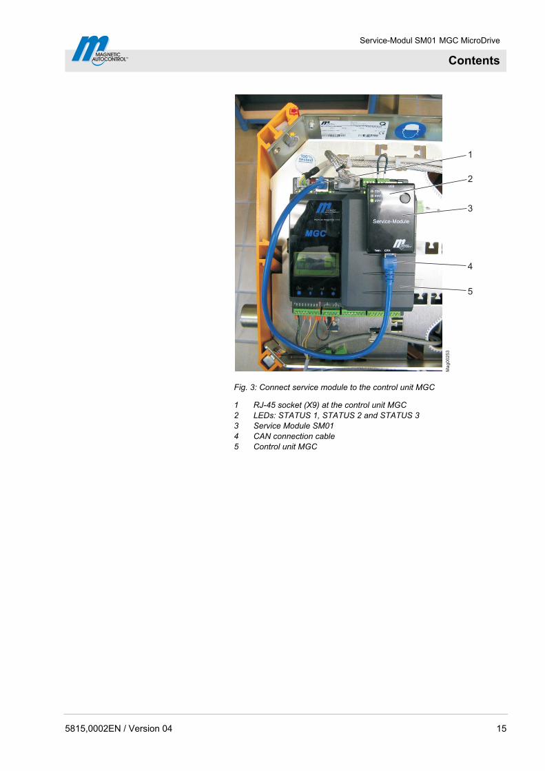
Fig. 3: Connect service module to the control unit MGC
1 RJ-45 socket (X9) at the control unit MGC 2 LEDs: STATUS 1, STATUS 2 and STATUS 3 3 Service Module SM01 4 CAN connection cable 5 Control unit MGC
5815,0002EN / Version 04 15
Service-Modul SM01 MGC MicroDrive
Contents
5.7 Install new firmware on the control unit and the plug-in modules
NOTE!
The entire installation process may take several minutes. The duration also depends on the number of modules plugged in.
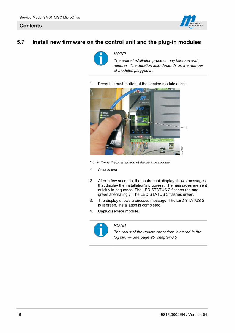
1. Press the push button at the service module once.
Mag00254
1
Fig. 4: Press the push button at the service module
1 Push button
2. After a few seconds, the control unit display shows messages that display the installation's progress. The messages are sent quickly in sequence. The LED STATUS 2 flashes red and green alternatingly. The LED STATUS 3 flashes green.
3. The display shows a success message. The LED STATUS 2 is lit green. Installation is completed.
4. Unplug service module.
NOTE!
The result of the update procedure is stored in the log file. See page 25, chapter 6.5.
16 5815,0002EN / Version 04
Service-Modul SM01 MGC MicroDrive
Contents
5.8 Assume Firmware factory settings for the control unit and enter the noted parameter settings
If the EEPROM structure has changed between the new and previous firmware, the current settings are overwritten by the default values of the firmware during an update. The control unit reports "0x6104 FW default values restored". In this case, you need to re-enter the user-specific settings.
5.9 MicroDrive Toll HighSpeed – installing new firmware on the motor
Motors of the barrier type Toll HighSpeed cannot be updated right by the MGC control unit.
If an update is necessary, the display shows the warning "0xFF38 Please update motor firmware". Depending on the change in the firmware, you can also continue to operate the barrier without the update.
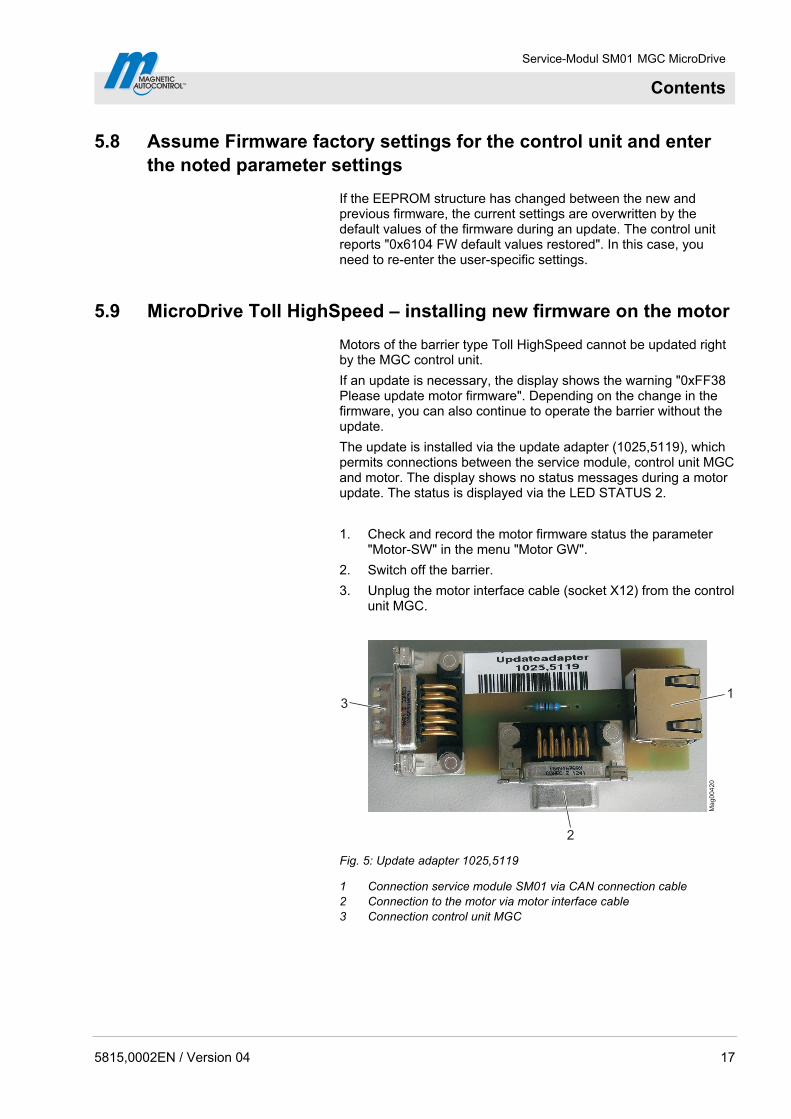
The update is installed via the update adapter (1025,5119), which permits connections between the service module, control unit MGC and motor. The display shows no status messages during a motor update. The status is displayed via the LED STATUS 2.
1. Check and record the motor firmware status the parameter "Motor-SW" in the menu "Motor GW".
2. Switch off the barrier.
3. Unplug the motor interface cable (socket X12) from the control unit MGC.
1
2
3M
ag
00
42
0
Fig. 5: Update adapter 1025,5119
1 Connection service module SM01 via CAN connection cable 2 Connection to the motor via motor interface cable 3 Connection control unit MGC
5815,0002EN / Version 04 17
Service-Modul SM01 MGC MicroDrive
Contents
18 5815,0002EN / Version 04
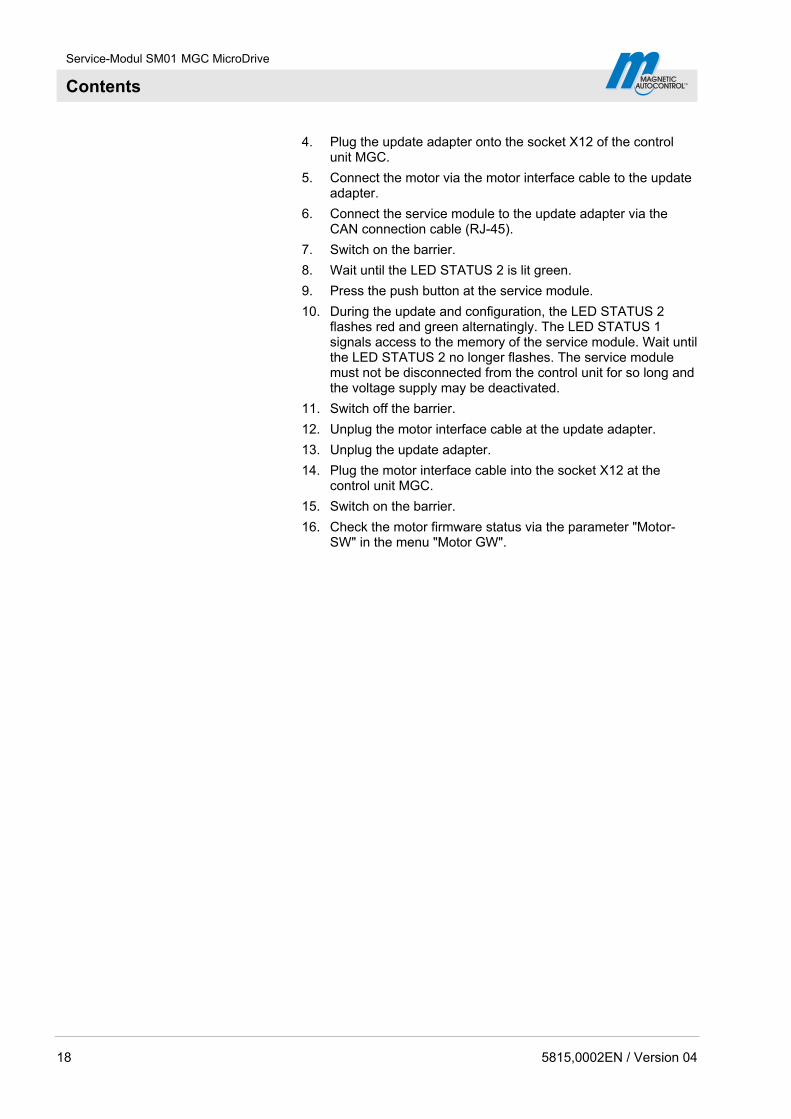
4. Plug the update adapter onto the socket X12 of the control unit MGC.
5. Connect the motor via the motor interface cable to the update adapter.
6. Connect the service module to the update adapter via the CAN connection cable (RJ-45).
7. Switch on the barrier.
8. Wait until the LED STATUS 2 is lit green.
9. Press the push button at the service module.
10. During the update and configuration, the LED STATUS 2 flashes red and green alternatingly. The LED STATUS 1 signals access to the memory of the service module. Wait until the LED STATUS 2 no longer flashes. The service module must not be disconnected from the control unit for so long and the voltage supply may be deactivated.
11. Switch off the barrier.
12. Unplug the motor interface cable at the update adapter.
13. Unplug the update adapter.
14. Plug the motor interface cable into the socket X12 at the control unit MGC.
15. Switch on the barrier.
16. Check the motor firmware status via the parameter "Motor-SW" in the menu "Motor GW".

Service-Modul SM01 MGC MicroDrive
Contents
6 Operation
6.1 Setting service mode, opening barrier
1. Secure barrier danger area e.g. with barrier tape.
2. Remove the barrier housing hood.
WARNING!
Danger of crushing between barrier boom and barrier housing!
3. Switch on service switch. The LED is lit red.
4. Manually open the barrier with the middle left button at thecontrol unit .
5. Unplug plug X11 for the light barrier connection from thecontrol unit.
5815,0002EN / Version 04 19
NOTE!
For the barrier to remain securely opened, we recommend pulling the plugs X11 at the control unit.
6. Switch off the barrier's voltage supply.
7. Plug the included CAN connection cable into the RJ-45 socketat the service module.
8. Plug the CAN connection cable into the RJ-45 socket (X9) atthe control unit MGC.
9. Switch on the barrier's voltage supply. The LED STATUS 2 islit green. LED STATUS 3 flashes or is lit green statically.
10. Wait briefly until the starting process of the control unit MGChas been completed.
6.2 Logger functions
6.2.1 Start and stop logger
Functions not available during logging
During logging of the CAN messages of the barrier, the following functions are not available:
Copying and inserting parameters via the service module.
Update of the firmware or parameterisation of the control unitand plug-in modules via the service module.
USB interface of the service module.

Service-Modul SM01 MGC MicroDrive
Contents
Start logger 1. Set service mode and open barrier according to chapter 6.1. See page 19, chapter 6.1.
2. The operating view is displayed. Press the right operating button at the control unit.
3. The "Main menu" menu is displayed.
4. Select the menu "Service Module" with the two middle buttons , .
5. Confirm selection with the right control button .
6. Select the parameter "Start/stop logger" with the two middle buttons , .
7. Confirm selection with the right control button . The message that the logger has been started appears on the display.
8. Press left operating button . The display shows the parameter "Start/stop logger" together with the icon [X]. The LED STATUS 2 is lit red. The logger is activated.
Once logged CAN messages are written to the SD card, the LED STATUS 1 flickers green.
NOTE!
During logging, the voltage supply must not be shut off. Deactivation of the voltage supply leads to data loss.
Stop logger 1. The operating view is displayed. Press the right operating button at the control unit.
2. The "Main menu" menu is displayed.
3. Select the menu "Service Module" with the two middle buttons , .
4. Confirm selection with the right control button .
5. Select the parameter "Start/stop logger" with the two middle buttons , .
6. Confirm selection with the right control button . The message that the logger has been stopped appears on the display.
7. Press left operating button . The display shows the parameter "Start/stop logger" together with the icon [ ]. The LED STATUS 2 is lit green. The logger is deactivated.
20 5815,0002EN / Version 04
Service-Modul SM01 MGC MicroDrive
Contents
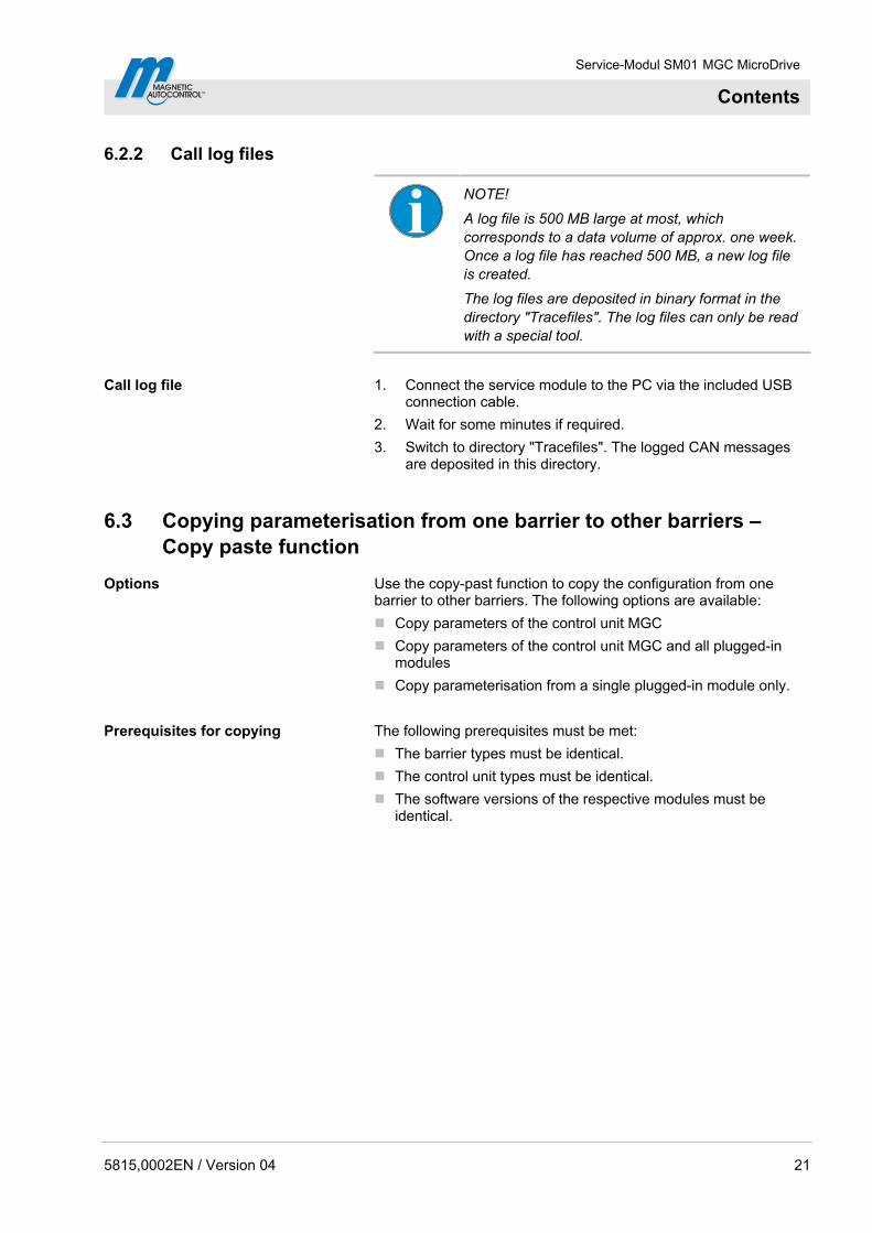
6.2.2 Call log files
5815,0002EN / Version 04 21
NOTE!
A log file is 500 MB large at most, which corresponds to a data volume of approx. one week. Once a log file has reached 500 MB, a new log file is created.
The log files are deposited in binary format in the directory "Tracefiles". The log files can only be read with a special tool.
Call log file 1. Connect the service module to the PC via the included USB connection cable.
2. Wait for some minutes if required.
3. Switch to directory "Tracefiles". The logged CAN messages are deposited in this directory.
6.3 Copying parameterisation from one barrier to other barriers – Copy paste function
Options Use the copy-past function to copy the configuration from one barrier to other barriers. The following options are available:
Copy parameters of the control unit MGC
Copy parameters of the control unit MGC and all plugged-in modules
Copy parameterisation from a single plugged-in module only.
Prerequisites for copying The following prerequisites must be met:
The barrier types must be identical.
The control unit types must be identical.
The software versions of the respective modules must be identical.
Service-Modul SM01 MGC MicroDrive
Contents
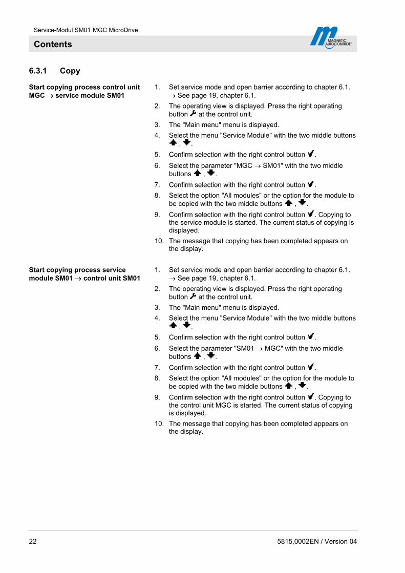
6.3.1 Copy
Start copying process control unit MGC service module SM01
1. Set service mode and open barrier according to chapter 6.1. See page 19, chapter 6.1.
2. The operating view is displayed. Press the right operating button at the control unit.
3. The "Main menu" menu is displayed.
4. Select the menu "Service Module" with the two middle buttons , .
5. Confirm selection with the right control button .
6. Select the parameter "MGC SM01" with the two middle buttons , .
7. Confirm selection with the right control button .
8. Select the option "All modules" or the option for the module to be copied with the two middle buttons , .
9. Confirm selection with the right control button . Copying to the service module is started. The current status of copying is displayed.
10. The message that copying has been completed appears on the display.
Start copying process service module SM01 control unit SM01
1. Set service mode and open barrier according to chapter 6.1. See page 19, chapter 6.1.
2. The operating view is displayed. Press the right operating button at the control unit.
3. The "Main menu" menu is displayed.
4. Select the menu "Service Module" with the two middle buttons , .
5. Confirm selection with the right control button .
6. Select the parameter "SM01 MGC" with the two middle buttons , .
7. Confirm selection with the right control button .
8. Select the option "All modules" or the option for the module to be copied with the two middle buttons , .
9. Confirm selection with the right control button . Copying to the control unit MGC is started. The current status of copying is displayed.
10. The message that copying has been completed appears on the display.
22 5815,0002EN / Version 04
Service-Modul SM01 MGC MicroDrive
Contents
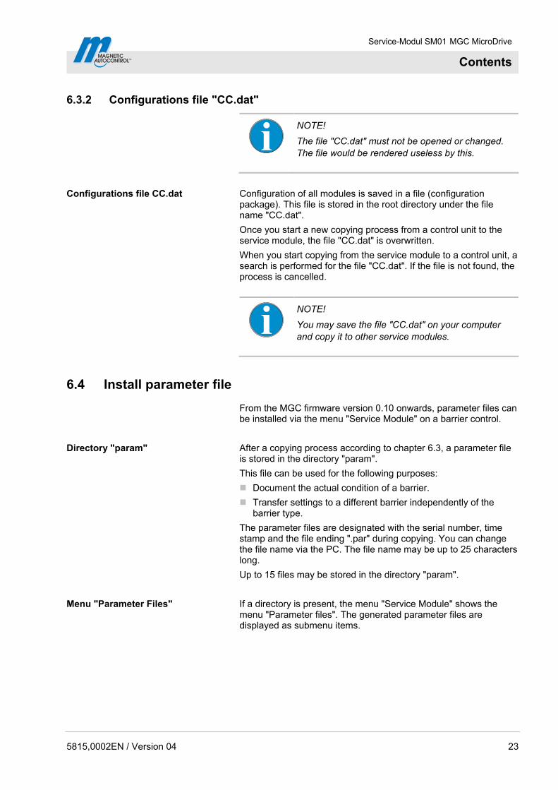
6.3.2 Configurations file "CC.dat"
5815,0002EN / Version 04 23
NOTE!
The file "CC.dat" must not be opened or changed. The file would be rendered useless by this.
Configurations file CC.dat Configuration of all modules is saved in a file (configuration package). This file is stored in the root directory under the file name "CC.dat".
Once you start a new copying process from a control unit to the service module, the file "CC.dat" is overwritten.
When you start copying from the service module to a control unit, a search is performed for the file "CC.dat". If the file is not found, the process is cancelled.
NOTE!
You may save the file "CC.dat" on your computer and copy it to other service modules.
6.4 Install parameter file
From the MGC firmware version 0.10 onwards, parameter files can be installed via the menu "Service Module" on a barrier control.
Directory "param" After a copying process according to chapter 6.3, a parameter file is stored in the directory "param".
This file can be used for the following purposes:
Document the actual condition of a barrier.
Transfer settings to a different barrier independently of the barrier type.
The parameter files are designated with the serial number, time stamp and the file ending ".par" during copying. You can change the file name via the PC. The file name may be up to 25 characters long.
Up to 15 files may be stored in the directory "param".
Menu "Parameter Files" If a directory is present, the menu "Service Module" shows the menu "Parameter files". The generated parameter files are displayed as submenu items.

Service-Modul SM01 MGC MicroDrive
Contents
Install parameter file on a barrier control
1. Set service mode and open barrier according to chapter 6.1. See to page 19, chapter 6.1.
2. The operating view is displayed. Press the right operating button at the control unit.
3. The "Main menu" menu is displayed.
4. Select the menu "Service Module" with the two middle buttons , .
5. Confirm selection with the right control button .
6. Select the menu "Parameter files" via the two middle buttons , .
7. Confirm selection with the right control button .
8. Select the desired parameter file with the two middle buttons , .
9. Confirm selection with the right control button . The settings of the parameter file are installed on the control unit.
Only the parameters are written that are present in the parameter record and the control unit. If the parameter set or the control unit comprises additional parameters, they are not written. The display shows a corresponding message.
Check and adjust parameters for induction loops
After copying, check the following parameters and just them for the induction loops if required:
Parameter "Sensitivity" in the menu "Detector"
Parameter "Freq. shift" in the menu "Frequency setting"
24 5815,0002EN / Version 04
Service-Modul SM01 MGC MicroDrive
Contents
5815,0002EN / Version 04 25
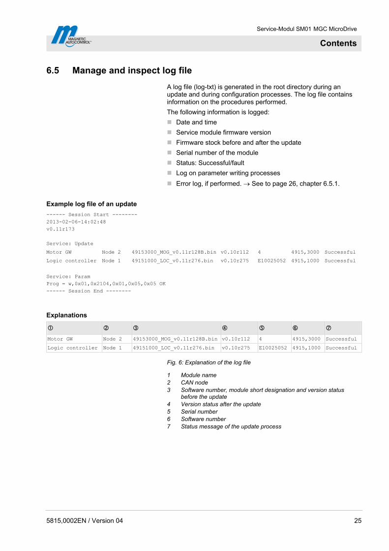
6.5 Manage and inspect log file
A log file (log-txt) is generated in the root directory during an update and during configuration processes. The log file contains information on the procedures performed.
The following information is logged:
Date and time
Service module firmware version
Firmware stock before and after the update
Serial number of the module
Status: Successful/fault
Log on parameter writing processes
Error log, if performed. See to page 26, chapter 6.5.1.
Example log file of an update
------ Session Start -------- 2013-02-06-14:02:48 v0.11r173 Service: Update
Motor GW Node 2 49153000_MOG_v0.11r128B.bin v0.10r112 4 4915,3000 Successful
Logic controller Node 1 49151000_LOC_v0.11r276.bin v0.10r275 E10025052 4915,1000 Successful
Service: Param Prog = w,0x01,0x2104,0x01,0x05,0x05 OK ------ Session End --------
Explanations
Motor GW Node 2 49153000_MOG_v0.11r128B.bin v0.10r112 4 4915,3000 Successful
Logic controller Node 1 49151000_LOC_v0.11r276.bin v0.10r275 E10025052 4915,1000 Successful
Fig. 6: Explanation of the log file
1 Module name 2 CAN node 3 Software number, module short designation and version status
before the update 4 Version status after the update 5 Serial number 6 Software number 7 Status message of the update process
Service-Modul SM01 MGC MicroDrive
Contents
26 5815,0002EN / Version 04
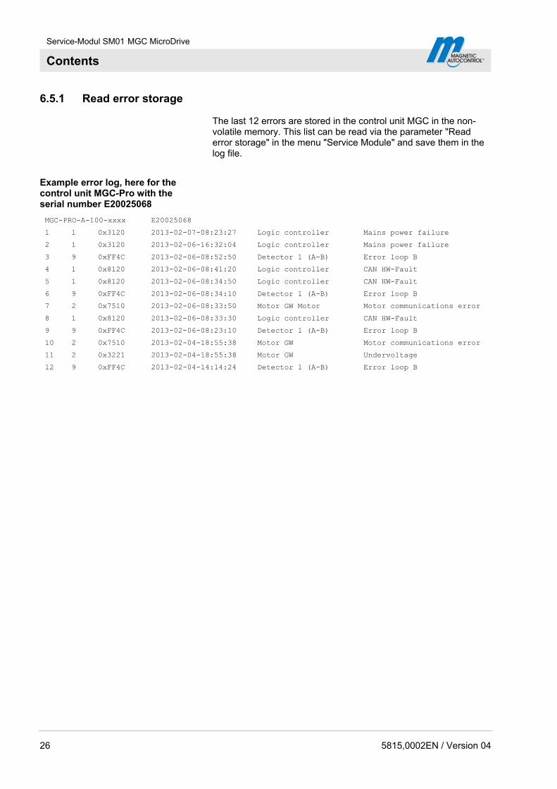
6.5.1 Read error storage
The last 12 errors are stored in the control unit MGC in the non-volatile memory. This list can be read via the parameter "Read error storage" in the menu "Service Module" and save them in the log file.
Example error log, here for the control unit MGC-Pro with the serial number E20025068
MGC-PRO-A-100-xxxx E20025068
1 1 0x3120 2013-02-07-08:23:27 Logic controller Mains power failure
2 1 0x3120 2013-02-06-16:32:04 Logic controller Mains power failure
3 9 0xFF4C 2013-02-06-08:52:50 Detector 1 (A-B) Error loop B
4 1 0x8120 2013-02-06-08:41:20 Logic controller CAN HW-Fault
5 1 0x8120 2013-02-06-08:34:50 Logic controller CAN HW-Fault
6 9 0xFF4C 2013-02-06-08:34:10 Detector 1 (A-B) Error loop B
7 2 0x7510 2013-02-06-08:33:50 Motor GW Motor Motor communications error
8 1 0x8120 2013-02-06-08:33:30 Logic controller CAN HW-Fault
9 9 0xFF4C 2013-02-06-08:23:10 Detector 1 (A-B) Error loop B
10 2 0x7510 2013-02-04-18:55:38 Motor GW Motor communications error
11 2 0x3221 2013-02-04-18:55:38 Motor GW Undervoltage
12 9 0xFF4C 2013-02-04-14:14:24 Detector 1 (A-B) Error loop B
Service-Modul SM01 MGC MicroDrive
Index
5815,0002EN / Version 04 27
Index
A
Application file ....................................................11
C
CC.dat.................................................................23Configurations file...............................................11 Copy parameterisation .......................................21 Copy paste function............................................21 Copying
Prerequisites ...................................................21 Copying process control unit MGC service module SM01.................................22
Copying process service module SM01 control unit MGC ........................................22
D
Design...................................................................8 Directory param ..................................................23
E
Environmental conditions .....................................8 Error log..............................................................26 Error storage
Read................................................................26
F
Firmware Control unit......................................................16 MicroDrive Toll HighSpeed .............................17 Plug-in modules ..............................................16 Service module ...............................................13
Function................................................................9
G
General .................................................................5
I
Intended use.........................................................7
L
LEDs.....................................................................9 Log file ................................................................21 Log File
Error log ..........................................................26 Manage ...........................................................25
Logger Start.................................................................20 Stop .................................................................20
M
MicroDrive Toll HighSpeed Installing new Motor Firmware ........................17
O
Operating systems................................................8
P
param..................................................................23 Parameter files....................................................23 Parameter settings
Write down ......................................................13 Pictogram explanation ..........................................5
S
Safety....................................................................7 Scope of delivery ..................................................6 Service module
Connect to the PC...........................................11 Install new firmware ........................................13 Install update.hex ............................................13 Select language ........................................11, 12
Status indicators ...................................................9
T
Technical data ......................................................8 Tracefiles ............................................................21
U
Update ................................................................10 Update adapter ...................................................17 update.hex ..........................................................11
W
Warning Notes ......................................................5
Z
ZIP file.................................................................11

Web: www.MagneticGateOpeners.com Phone: (800) 878-7829Fax: (330) 650-9004Email: [email protected]