service manual new electronics cooking 2006servicenet.indesitcompany.com/data/img_sm/sm27721.pdf ·...
TRANSCRIPT

SERVICE MANUAL
New Electronics Cooking 2006
SERVICE MANUAL
New Electronics Cooking 2006
GB
All the parts included in this document are the property of Indesit Company S.p.A.
All rights reserved. This document and the information it contains are supplied without liability for pos-sible errors or omissions; no part of this document can be reproduced, used or copied without written permission or without being authorised by the terms of a contract clause.
Service ManualNew Electronics - 2006
Edition2006.03.13
LanguageEnglish
GB
2
Service ManualNew Electronics - 2006
Edition2006.03.30
LanguageEnglish
CONTENTS OF THE MANUAL: NOTE FOR THE TECHNICIAN.This manual is a supporting document for technical personnel. It contains a description of the various pro-duct types, the general working principle, and indications regarding assistance.
Technical personnel should consult the specifi c model(www.servicenet.indesitcompany.com) for data and updates on wiring diagrams, technical infor-mation and spare parts.

GB
3
Service ManualNew Electronics - 2006
Edition2006.03.30
LanguageEnglish
CONTENTS
1. PRODUCT TYPE 4-8 Key - Ariston 4 Key - Scholtes 4 Key - Hot Point 4 U.I. interface. Base Pirò 5 Interface E1 6 David Lewis Piezo Pirò Interface 7-8
2. OPERATING LOGIC 9-11 Product features and innovations 9-11 Cooking programmes 11
3. COMPONENTS 12-13
4. WIRING DIAGRAMS 14-15
5. ASSISTANCE 16-26 Hardware key access port 16 U.I. interface. Base - Auto Test - Demo Mode 17 E1 interface – Self-Test - Demo Mode 18 David Lewis Interface – Self-Test - Demo Mode 19 Troubleshooting 20-21 Sensors table 22 Removal of U.I. Base E1 23 David Lewis removal 24-25
6. DAVID LEWIS EXPLODED VIEWS 26-27
7. APPENDICES 28-44 PTC sensors value 28 Multi 10--E1 7.1 development PTC SENSOR VALUES: 29-32 David Lewis F48 cycles 33-44

PR
OD
UC
T
GB
4
LanguageEnglish
Service ManualNew Electronics - 2006
Edition2006.03.13
TYPEF= B.I. free-standing ovensH=B.I. built-in ovensP=MultifunctionD=Double ovenM=Maxioven
PRODUCTS LINEB= StyleC=ClassD=DiamondR=DecòT=TraditionZ=ExperienceQ=Glass experienceG=Gas
COOKING FUNCTIONS1=Static2=Static+turnspit3=Fan4=Fan +turnspit5=Multi 56=Multi 5+turnspit7=6-functions + turnspit8=Multi 79=Multi 7+ turnspit10=Multi 10
TYPE OF TIMER0= None1=timer2=Timer+end of cooking4=Clock5=Analogue Timer6=Electronic timer7=Integral timer: Time + Temperature8=Digital9=E0
CLEANINGC=CatalyticP=Self-cleaning (Pyrolysis)B= Manual
ENERGY CLASS1=Class A2=Class B3=Class C
COLOURAN=AnthraciteIX=S/steelMI= S/steel Miroir MA=Anthracite Miroir WH=WhiteBK= BlackICE=GreyGR= Graphite
ELECTRONICSY= electronics 2005
The ovens listed below have the same aesthetics and commercial code; they are equipped with the new electronics; the Y after the model identifi es them
Original description FZ 62 P.1 IXFZ 61 P.1 IXH60 V P.1 IX
New descriptionFZ 62 P.1 IX / YFZ 61 P.1 IX / YH60V P.1 IX / Y
Unchanged codes340113157233090
TYPEF= OVENS
PRODUCT LINEX=AXIOMM= PRISM
G=GALBE
L=LEWIS
ELECTRONICS TYPE3=9 cooking functions (Creation)4=9 cooking functions(creation) & 9 automatic (Success)6=12 cooking functions (creation) & 11 automatic (success)
TYPES= SINGLE OVEND= DOUBLE OVENE=Experience
PRODUCT LINEC=ClassD=Diamone
Y=Style
USER INTERFACE100=“touch” control
CLEANING TYPEP=Pyrolyticb=Manual
TYPES= SINGLE OVEND= DOUBLE OVEN
PRODUCTS LINEC=ClassD=DiamoneE= ExperienceY=Style
COOKING FUNCTIONS8=multi 86=multi 65=multi 53= Fan2=gas
USER INTERFACE8= Smart display7=DAC6=Digital timer5=Analogue timer2=End of cooking timer1=Timer
CLEANING TYPEP=Pyrolyticb=Manual
1. PRODUCT TYPE:
1.1. KEY - ARISTON PRODUCTS:
F Z 6 1 P .1 IX Y
1.2. KEY - SCHOLTES PRODUCTS:
F L 4 6 .1 IX
1.3. KEY - HOT POINT PRODUCTS:
S E 100 P
S E 8 7 P
CLEANING TYPE4=Manual5=Catalytic
6=Self-cleaning (Pyrolysis)
ENERGY CLASS.1 = Class A.2 = Class B
.3 = Class C
COLOURAN=AnthraciteIX=S/steel
MI=S/steel Miroir
MA=Anthracite MiroirWH=WhiteGI=Gris Iceberg (grey)VA=Vert Amazone (green)BA=Bleu Atol (light blue)MT= MirrorBK= Black

PR
OD
UC
T
GB
5
LanguageEnglish
Service ManualNew Electronics - 2006
Edition2006.03.13
1.3 U.I. PRODUCT TYPE PIRO’ BASE:It is equipped with the main board with the new electronics, mechanical/electromechanical timer and two potentiometers.
The left LED indicates an active cooking cycle, whe-reas the right LED indicates if the door is locked.
Both LEDs are used to signal possible faults by simul-taneously emitting a series of fl ashes interrupted by a pause (similar to Washing-machine and Dishwasher).
DATA PLATE
Dimensionswidth 43.5 cmheight 32 cmdepth 41,5 cm
Volume lt. 58
Electricalconnections
voltage: 220-240V ~ 50/60Hzmaximum power absorbed2800W
ENERGY LABEL
Directive 2002/40/EC on the labelof electric ovens.Standard EN 50304
Energy consumption for Naturalconvection – heating mode:Convection mode.
Declared energy consumption forForced convection Class – heatingmode: Baking.
This appliance conforms to thefollowing European EconomicCommunity directives:73/23/EEC of 19/02/73 (LowVoltage) and subsequentamendments;- 89/336/EEC of 03/05/89(Electromagnetic Compatibility) andsubsequent amendments;- 93/68/EEC of 22/07/93 andsubsequent amendments.- 2002/96/EC
KnobPROGRAMMES
KnobTIMER*
KnobTHERMOSTAT
Light- PREHEATING (flashing)- PROGRAMME IN PROGRESS (fixed)- ERROR SIGNAL (rapid flashing)
LightDOOR LOCKED*
position 5position 4position 3position 2position 1
Control panel
GRILL shelf
DRIP TRAY shelf
RUNNERSfor shelves
Control panel
Control panel

PR
OD
UC
T
GB
6
LanguageEnglish
Service ManualNew Electronics - 2006
Edition2006.03.13
1.3 PRODUCT TYPE E1:
All settings are carried out by pressing the PIEZO icons.
Selection of functions is supported by “PIEZO” te-chnology; lightly pressing the icon corresponding to the required function generates a potential difference that is processed by the MAIN board.
Control panel
position 5position 4position 3position 2position 1
Control panel
GRILL shelf
DRIP TRAY shelf
RUNNERSfor shelves
DATA PLATE
Dimensions
Dimensions
Electrical
connections
ENERGY
LABEL
width 43.5 cm
height 32 cmdepth 40 cm
lt. 56
width 43.5 cm
height 32 cmdepth 41,5 cm
lt. 58
voltage: 220-240V ~ 50/60
Hzmaximum power absorbed
2800W
Directive 2002/40/EC
on the labelof electric ovens.
Standard EN 50304
Declared energy consumption
forForced convection Class –
heatingmode: Browning.
This appliance conforms to thefollowing
European Economic Community
directives: 73/23/EEC of 19/02/73
(LowVoltage) and subsequentamend-
ments;- 89/336/EEC of
03/05/89(Electromagnetic Compatibility)
andsubsequent amendments;-
93/68/EEC of 22/07/93 andsubsequent
amendments.- 2002/96/EC

PR
OD
UC
T
GB
7
LanguageEnglish
Service ManualNew Electronics - 2006
Edition2006.03.13
1.3 OVEN TYPE DAVID LEWIS 48 CM PIEZO PIRO’:
Function selection technology is “PIEZO” type. The board is PIRO’ type, since the “door lock” safety function is always present
The pyrolysis function is activated by the correspon-ding icon. The button for switching on/off the light inside the oven is on appliances without this function (non-pyrolytic products).
Drop Down type control panel
Example of display in cooking phase:
17.10 0:45
210° C
CREATION Tradition PRESS START
TIMEDURATION
Indication ofMenu selected
Suggests what to do or what the oven is doing
Selected cooking time icon/recommendedcooking shelf icon
Temperature indication
Preheatingindicators
IndicationTIME;COOKING DURATION;END OF COOKING;TIMER
CrèationProgrammes selection
Times adjustment
Downarrow
Uparrow
START/STOP
Settingsbutton
ON/OFF
NextProgrammes selection
Temperature control
DISPLAY OKbutton Pyrolysis
or Lightbutton
Controls lockbutton
oLuce

PR
OD
UC
T
GB
8
LanguageEnglish
Service ManualNew Electronics - 2006
Edition2006.03.13
LATERAL DOOR control panel
Control panel Drop Down
Display
17.10 0:45
210° C
CREATION Tradition PRESS START
TIMEDURATION
Indication ofMenu selected
Suggests what to do or what the oven is doing
Selected cooking time icon/recommendedcooking shelf icon
Temperature indication
Preheatingindicators
IndicationTIME;COOKING DURATION;END OF COOKING;TIMER
CrèationProgrammes selection
Times adjustment
Downarrow
Uparrow
START/STOP
Settingsbutton
ON/OFF
NextProgrammes selection
Temperature control
DISPLAY OKbutton Pyrolysis
or Lightbutton
Controls lockbutton
TABLE OF CHARACTERISTICS
Dimensions *width 43.5 cmheight 32 cmdepth 41.5 cm
Volume * 58 l
Electricalconnections
voltage: 220-240V ~ 50Hz /maximum power absorbed 2560 -3050 W
ENERGYLABEL *
Directive 2002/40/EC on the labelof electric ovens.Standard EN 50304
Energy consumption for Natural
convection – heating mode: Traditional mode;
Declared energy consumption forForced convection Class – heating
mode: Rotisserie.This appliance conforms to thefollowing European EconomicCommunity directives:73/23/EEC dated 19/02/73 (LowVoltage) and subsequentamendments;89/336/EEC dated 03/05/89(Electromagnetic Compatibility) andsubsequent amendments;93/68/EEC dated 22/07/93 andsubsequent amendments.2002/96/EEC

OP
ER
AT
ING
GB
9
LanguageEnglish
Service ManualNew Electronics - 2006
Edition2006.03.13
2. OPERATING LOGIC:
2.1. PRODUCT FEATURES AND TECHNOLOGICAL INNOVATIONS:
MAIN BOARD:
Like the refrigerator/washing machine/dishwasher mo-dels it is equipped with a power module and micropro-cessor module and is shared by all platforms, whereas the board is specifi c for the Hot 2005 product.
• UI-Base Pirò/ E0 Pirò/E1 Pirò/ D.L. Pirò/ D.L. non-Pirò (sc. code 16200120501)
• UI-Base non-Pirò/ E0 non-Pirò/E1 non-Pirò/ (sc. code 16200136100)
• UK double oven
• The PIRO’ board is also equipped with a main relay in compliance with regulations.
The non-PIRO’ board and the double oven do not have a safety relay because the pyrolysis function is not present.
The main relay disconnects the power to the heating elements in the presence of risk temperatures:
1. Temperature too high Main Board F04 85°C
2. Temperature too high Visual Board (for E0 only) F05 80°C
3. Temperature too high during cooking cycle F06 subc 01 360°C
4. Temperature too high during pyrolysis cycle F06 subc 02 550°C
All the main boards are equipped with a hardware key input for activating the connection with a han-dheld/PC
POTENTIOMETERSBoth potentiometers have three common outputs and two communication points RH/LH. The measurement is performed by checking the ohmic integrity of the tracks.
The check is performed by selecting the different PRO-GRAMMES/TEMPERATURE and measuring the ohmic values between the common contact and RH/LH
– they are used as a function selector on UI-Base, E0, double oven (version with selector)
– they are used to set temperatures on UI-base and double oven for top chamber (continuous adjust-ment version) POTENTIOMETERS
PULSE LOCK DOOR AND DOOR CLOSED MICROSWITCHThe door lock device is present in all PIRO’ ovens and some non-PIRO’ ovens (e.g. all D. L. non-PIRO’ models).
In addition to locking the door in PYROLYSIS fun-ction, it is also used for communicating with the electronics if the door is closed or open. If the door is open, in any function, the power to the heating elements and internal fan is disconnected
MAIN RELAY

OP
ER
AT
ING
GB
10
LanguageEnglish
Service ManualNew Electronics - 2006
Edition2006.03.13
The “fl oor” heating element has been eliminated.
The optimum distribution of heat inside the oven chamber is in any case guaranteed by the new shape of the internal fan protection.
DOOR SEAL ON D.L. 48 AND ALL FULL GLASS DOORS
The lower part is free to facilitate the fl ow of supe-rheated air
The upper part has profi les to block the fl ow of supe-rheated air and facilitate the fl ow in the lower part
It is housed on the oven chamber and no longer on the oven door.
NEW FULL DOORExclusively for DAVID LEWIS models Scholtes FULL GLASS type, houses the oven controls on the handle.
HEATING ELEMENTS AND OPTIMISING HEAT DISTRIBUTION INSIDE THE OVEN

OP
ER
AT
ING
GB
11
LanguageEnglish
Service ManualNew Electronics - 2006
Edition2006.03.13
COOKING PROGRAMME MANAGEMENTThe new electronics enable management of manual programmes (CREATION). Described below are all the cooking cycles, from which it will be noted that:
• The preheating programme stops when the temperature reached is approx. 10°C lower than the set temperature
• The grill and circular heating elements are fed according to the attached diagram, like during the cooking cycle.
• The cooking duration is infi nite. In any case, the user can set a cooking time up to a max. of 23 hours and 59 minutes.
AUTOMATIC PROGRAMMESThe automatic programmes are defi ned as SUCCESS programmes.
They are designed and optimised to offer good cooking results according to the food for which they were created.
The SUCCESS programme features a preset time within which the following are activated:
• Preheating• cooking • possible recovery time.Preheating can occur very quickly if the oven is already hot from previous cooking. In any case the cooking cycle will end at the preset time. If the oven temperature is higher than that required by the new cooking programme, preheating is not carried out.
2.2. COOKING PROGRAMMES:
Temperature Time Tangential Turbine
Floor a 0
Grill b 100
Circ k 0
Floor a 4
Grill b 50
Circ k 0
Floor a 4
Grill b 50
Circ k 0
* When function is started: If Oven Temp. < 120°C -->, Cooking time 35'
If Oven Temp. > 120°C -->, Cooking time 30'
** The duration of the recovery phase depends on the time employed in the preheating phase to bring the oven
up to the preset temperature, and on the cooking time.
The total duration of the cooking cycle will always be 45', including preheating.
Param.
GV
GV
CAKES Automatic 2R PyroCycling
Cooking 190 No
change
35' *
30'MV
Preheating Turnspit =
OFFMV
OFF
Lighting = ON
Turnspit = OFF
Recovery 50 No
change
10' **
15'MV

CO
MP
ON
EN
TS
GB
12
LanguageEnglish
Service ManualNew Electronics - 2006
Edition2006.03.13
3. COMPONENTS:
MAIN BOARD1 HW key connection port
2 Safety relay (PIRO’ only)
3 Power module
E1 DISPLAY BOARD1 Communication with main board
2 PIEZO controls support
3 Communication cable between PIEZO controls and board
4 Steam protection
2
3
5
4
1
4 Microprocessor module
5 SAT Eeprom socket
2
3
4
1

CO
MP
ON
EN
TS
GB
13
LanguageEnglish
Service ManualNew Electronics - 2006
Edition2006.03.13
HEATING ELEMENTSThe “FLOOR” heating element has been eliminated; therefore the following are installed:
1 Roof heating element (Grill)
2 Circular heating element
DOOR LOCK AND DOOR OPEN/CLOSED SENSOR1 Door open/closed switch2 Door locking pulse device
DOOR SEAL
D.L. FULL GLASS DOOR
POTENTIOMETERS
2
1
21

DIA
GR
AM
S
GB
14
LanguageEnglish
Service ManualNew Electronics - 2006
Edition2006.03.13
4. WIRING DIAGRAMS:
Blo
cco
porta
J6/J
5
H5
H6
H4
H2
SO
ND
AT
EM
PE
RA
TU
RA
H8
H1
Spie
LE
D
Display
Co
nta
ttote
rra
Sele
ttore
funzio
ni
Pote
nzio
metro
tem
pera
tura
I²Cp
rogra
mm
azio
ne
sch
ed
a
So
nda
fum
i
/So
nd
a to
p o
ve
n
Lu
ce
54
32
13
21
1
Ta
ng
enzia
le
Gira
rrosto
Mo
tove
ntila
tore
J1
J2
J3
J4
J8/J
14
J9
J10
J13
J12
J16
I²Csonde
J11
J17 B
J7
11
1
1
1
1
1
1
1
1
L N
TANG
TP
2
L
Cielo
Circ.
LF
J17 A
1
MV
FUS.
FUS.
BLOCCO PORTA
portabloccata
portachiusa
L
N
1
8TP
3
4
5
6
1
2LED BLOCCOPORTA
LED FUNZ. TERMOST.
FINE COTTURA
FUNZIONI
POTENZIOMETRO
SONDA
CHIAVE HW
4.1. PIRÒ / UI BASE / E0 / E1 / DL DIAGRAM
DIA
GR
AM
S
GB
15
LanguageEnglish
Service ManualNew Electronics - 2006
Edition2006.03.13
J6/J
5
H5
H6
H4
H2
SO
ND
AT
EM
PE
RA
TU
RA
H8
H1
Sp
ie L
ED
Display
Co
nta
ttote
rra
Se
letto
re fu
nzio
ni
Pote
nzio
me
trote
mp
era
tura
I²Cpro
gra
mm
azio
ne
sched
a
So
nd
a fu
mi
/So
nda
top
ove
n
Luce
54
32
13
21
1
Ta
ng
enzia
le
Gira
rrosto
Moto
ventila
tore
J1
J2
J3
J4
J8/J
14
J9
J10
J13
J12
J16
I²Csonde
J11
J17 B
J7
11
1
1
1
1
1
1
1
1
L N
TANG
MV
TP
2
L
Cielo
Circ.
LF
J17 A
1
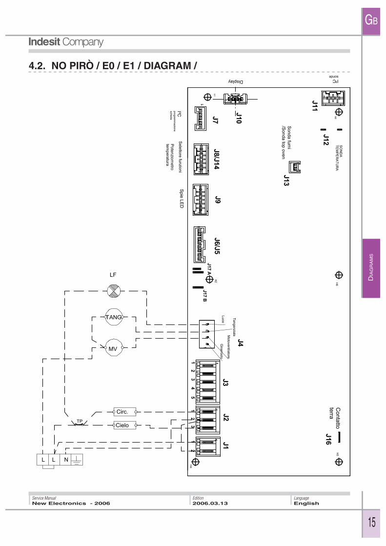
4.2. NO PIRÒ / E0 / E1 / DIAGRAM /
AS
SIS
TA
NC
E
GB
16
LanguageEnglish
Service ManualNew Electronics - 2006
Edition2006.03.13
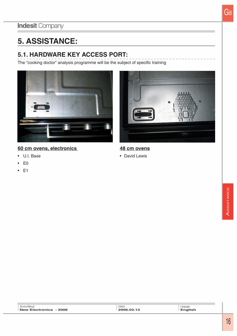
60 cm ovens, electronics • U.I. Base
• E0
• E1
48 cm ovens • David Lewis
5. ASSISTANCE:
5.1. HARDWARE KEY ACCESS PORT:The “cooking doctor” analysis programme will be the subject of specifi c training

AS
SIS
TA
NC
E
GB
17
LanguageEnglish
Service ManualNew Electronics - 2006
Edition2006.03.13
5.2. BASIC INTERFACE (UIBASE):
5.2.1 Display of FaultsThe fault is displayed by fast simultaneous fl ashing of LED1 and LED2 (Ton = 300 ms , Toff = 300 ms). The number of fl ashes indicates the fault number, the series of fl ashes is interrupted by a 1.2 sec pause.
5.2. 2. Self-TestThe self-test cycle activation sequence is as follows:
Step 0 Pot1 and Pot2 are both set to MAX. The start/end cooking switch (S/E Cooking) is set to 20/30 min.
Step 1 Turn the S/E Cooking switch from: 20/30 min � Off (dot) � ON (hand)
Step 2 Turn Pot2 from: Max 0 � Max � 0 � Max
Step 3 Turn Pot1 from: Max � 1 passing through all intermediate positions (“pause” on intermediate positions of approx. 1 sec)
The sequence will be interrupted if the time between any of the transitions is more than 10 sec, or if a tran-sition different from those described is carried out.
If the S/E Cooking switch is not present, skip step 1
At the same time as starting of the self-test the last fault (LastFault) is displayed three times (3 sequences of fl ashes), after which the LastFault is deleted.
The self-test cycle consists of:
5.2. 3. DemoUIBase ovens are not equipped with Demo mode.
DoorLock Tangent. fan Oven fan Lamp TurnspitGrill
Step 1 8sec
X(pirò only)
X(max speed)
Step 2 8sec
X(max speed)
Step 3 15sec
X X(max speed)
X X
Step 4 15sec
X(max speed)
X XX
Circ. h.e.

AS
SIS
TA
NC
E
GB
18
LanguageEnglish
Service ManualNew Electronics - 2006
Edition2006.03.13
5.2. E1 INTERFACE:
5.2.1 Display of FaultsThe fault is displayed in the left digits: “FXX” fl ashes (XX=fault number).
5.2. 2. Self-TestL During the self-test cycle the message “Sat” is displayed in the right digits.
The self-test cycle activation sequence is as follows:
Press all buttons from right to left, then press the second from the right again:+_times -_times Clock FastClean/Lamp AutoRecipes Temperature+ Temperature- Ma-nualRecipes On/Off +_times Start/Stop -_timesThe sequence will be interrupted if the time between any of the transitions is more than 2 sec.At the same time as starting of the self-test the last fault (LastFault) is displayed six times (6 fl ashes).
The self-test cycle consists of:
5.2. 3. DemoDemo mode is not currently available in E1 ovens but will implemented in the future:
It starts from ON status
Activation: On/Off � Start �+_times
Deactivation: On/Off � -_times
N.B.: The time between pressing buttons for activation must not exceed 1 second.The time between pressing buttons for deactivation must not exceed 5 seconds.
DoorLock Tangent. fan Oven fan Lamp TurnspitGrill
Step 1 8sec
X(pirò only)
X(max speed)
Step 2 8sec
X(max speed)
Step 3 15sec
X X(max speed)
X X
Step 4 15sec
X(max speed)
X XX
Circ. h.e.
FXX SAT
AS
SIS
TA
NC
E
GB
19
LanguageEnglish
Service ManualNew Electronics - 2006
Edition2006.03.13
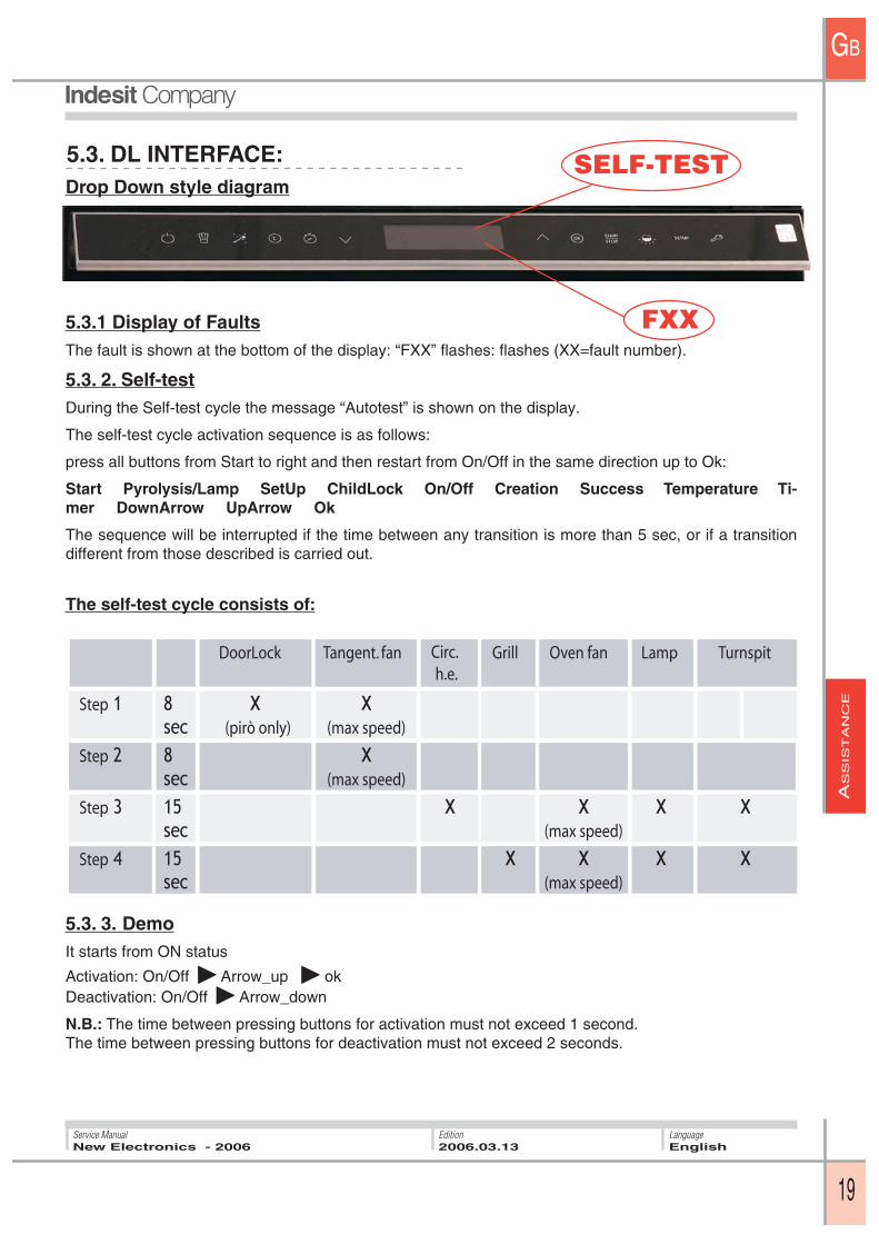
5.3. DL INTERFACE:
5.3.1 Display of FaultsThe fault is shown at the bottom of the display: “FXX” fl ashes: fl ashes (XX=fault number).
5.3. 2. Self-testDuring the Self-test cycle the message “Autotest” is shown on the display.
The self-test cycle activation sequence is as follows:
press all buttons from Start to right and then restart from On/Off in the same direction up to Ok:
Start Pyrolysis/Lamp SetUp ChildLock On/Off Creation Success Temperature Ti-mer DownArrow UpArrow Ok
The sequence will be interrupted if the time between any transition is more than 5 sec, or if a transition different from those described is carried out.
The self-test cycle consists of:
5.3. 3. DemoIt starts from ON status
Activation: On/Off � Arrow_up � okDeactivation: On/Off � Arrow_down
N.B.: The time between pressing buttons for activation must not exceed 1 second.The time between pressing buttons for deactivation must not exceed 2 seconds.
Drop Down style diagram
DoorLock Tangent. fan Oven fan Lamp TurnspitGrill
Step 1 8sec
X(pirò only)
X(max speed)
Step 2 8sec
X(max speed)
Step 3 15sec
X X(max speed)
X X
Step 4 15sec
X(max speed)
X XX
Circ. h.e.
SELF-TEST
FXX

AS
SIS
TA
NC
E
GB
20
LanguageEnglish
Service ManualNew Electronics - 2006
Edition2006.03.13
FAULT ANALYSISSUBCODE
F01
F01
F01
5.4. FAULTS TABLE:
The electronics periodically check for the presence of anomalous situations regarding:
• Loads
• Values of inputs
• Correct communication between boards
If an anomalous situation lasts for a predetermined time, the application switches to fault status and the majority of functions, including the cooking cycle, are stopped. In fault status, the safety procedures (tan-gential fan control) and signalling procedures (fan control and fault display on user interface) are activated. If the cause of the fault does not reappear for a predetermined time, an automatic reset is performed; in which case the fault is stored and the appliance will be available for use. A special case where the fault can be reset automatically is that of faults that are blocking only for certain functions, e.g.:
• door lock fault, which is reset if a cycle other than pyrolysis is set.
Monitoring of faults also enables the identifi cation of warnings that do not involve the transition to fault status: the warnings are not displayed but can be monitored during assistance with the aid of handheld/PC.
L’identifi catore del fault è composto da 2 parti:
• CODE used for the display on the user interface
• SUBCODE, used for detailed information and accessible only with the aid of the handheld/PC
The faults can be grouped by type:
CODE DETAIL
Main board sensor
Setting File
Heat ing ele-ment circui t :Triac in short circuit or relay stuck
Heat ing ele-ment circui t :Triac open or relay not clo-sing
F01
01020304
1112
41424344454647
51525354555657
SCOCIrregularUnstable
MainVisual
Chamber Main fl oor heating el.Chamber Main circular heating elChamber Main grill heating el.Chamber Main steam heating el.Chamber Top fl oor heating el.Chamber top grill 1 heating el.Chamber top grill 2 heating el
Chamber Main fl oor heating el.Chamber Main circular heating el.Chamber Main grill heating el.Chamber Main steam heating el.Chamber Top fl oor heating el.Chamber top grill 1 heating el.Chamber top grill 2 heating el.
Reprogramme the eeprom
5.4.1 FAULTS relevant to the MAIN board:
AS
SIS
TA
NC
E
GB
21
LanguageEnglish
Service ManualNew Electronics - 2006
Edition2006.03.13
FAULT ANALYSISSUBCODE
F02
F02
CODE DETAIL
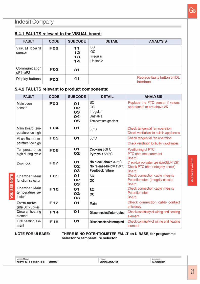
Visual board sensor
Communication uP1-uP2
Display buttons
F02
11121314
31
41
SCOCIrregularUnstable
5.4.1 FAULTS relevant to the VISUAL board:
FAULT ANALYSISSUBCODE
F07
F05
F06
CODE DETAIL
Main oven sensor
Main Board tem-perature too high
Visual Board tem-perature too high
Temperature too high during cycle
Door lock
Chamber Main function selector
Chamber Main temperature se-lector
Communication(after 30’’ x 5 times)Circular heating element
Grill heating ele-ment
F04
0102030405
01
01
0102
01020301020301020301
01
01
SCOCIrregularUnstableTemperature gradient
85°C
80°C
Cooking 360°CPyrolysis 550°C
No block-above 325°CNo release-below 150°CFeedback failure
SCOC
SCOC
Main
Disconnected/interrupted
Disconnected/interrupted
Replace the PTC sensor if values approach 0 or are above 2K
Check tangential fan operationCheck ventilation for built-in appliances
Check tangential fan operation
Check ventilation for built-in appliances
Positioning of PTCPTC ohm measurementBoardCheck door lock system operation (SELF-TEST)Check PTC ohm (Integrity check)BoardCheck connection cable integrityPotentiometer (Integrity check)BoardCheck connection cable integrityPotentiometerBoard
Check connection cable contact effi ciency
Check continuity of wiring and heating element
Check continuity of wiring and heating element
5.4.2 FAULTS relevant to product components:
F12
F10
F09
F03
F15
F14
NOTE FOR UI BASE: THERE IS NO POTENTIOMETER FAULT on UIBASE, for programme selector or temperature selector
Replace faulty button on DL interface
YOU
SE
E N
OTE

AS
SIS
TA
NC
E
GB
22
LanguageEnglish
Service ManualNew Electronics - 2006
Edition2006.03.13
5.5. U.I.BASE/E1 REMOVAL:U.I.BASE/E1 MAIN BOARD:
2. Remove the oven roof, making sure to disconnect cable Hk
3. Position connector HK in order to prevent a pos-sible short circuit.
4. Remove the connectors from board and remove the board from seat.
U.I.BASE/E1 DISPLAY CARD:
2. Remove the oven roof, making sure to disconnect cable Hk
3. Disconnect the fl at cable and the main board connection cable
4. Release the hooks holding the display card and replace the card.
1. Disconnect the power supply
1. Disconnect the power supply
AS
SIS
TA
NC
E
GB
23
LanguageEnglish
Service ManualNew Electronics - 2006
Edition2006.03.13
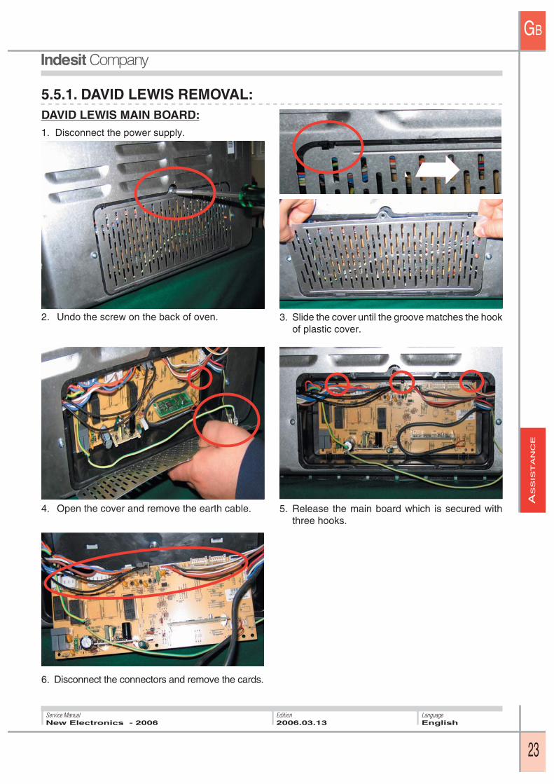
5.5.1. DAVID LEWIS REMOVAL:DAVID LEWIS MAIN BOARD:1. Disconnect the power supply.
6. Disconnect the connectors and remove the cards.
2. Undo the screw on the back of oven. 3. Slide the cover until the groove matches the hook of plastic cover.
4. Open the cover and remove the earth cable. 5. Release the main board which is secured with three hooks.

AS
SIS
TA
NC
E
GB
24
LanguageEnglish
Service ManualNew Electronics - 2006
Edition2006.03.13
2. Remove the two connectors through the slot in the base.
3. Block the hinge and remove the door.
1. Open the hatch at the bottom left and disconnect the cables.
DAVID LEWIS FULL GLASS DOOR RE-MOVAL:
Remove the oven door N.B.: To refi t the door, make sure to use the fi rst recess shown in the fi gure
DAVID LEWIS DISPLAY BOARD REMO-VAL:
1. Access fi xing screws (under door handle).
2. Remove the 4 visual board support fixing screws.
3. Disconnect the fl at cable and replace the visual board.

EX
PLO
DE
DV
IEW
S
GB
25
LanguageEnglish
Service ManualNew Electronics - 2006
Edition2006.03.13
6. David Lewis 48 CM EXPLODED VIEWS:
1 oven roof2 right side panel 3 side handle 4 oven front panel 5 oven door seal 6 door glass right trim 7 3-glass door seal 8 inside glass 9 oven door hinge 10 door handle bracket 11 handle structure 12 oven door outside glass 13 door glass bracket
Ref. description
14 inside glass rubber 15 side seal 16 oven door third glass 17 oven door left trim 18 upper trim19 oven fl oor20 oven fl oor defl ector 21 side trap 22 connector support 23 left side panel 24 oven fi xing bracket 25 oven back 26 back trap
Ref. description
1
2
3
4
5
6
7
8
9
10
11
12
13
8
14
9
15
16
17
18
19
20
21
22
3
23
24
25
26

EX
PLO
DE
DV
IEW
S
GB
26
LanguageEnglish
Service ManualNew Electronics - 2006
Edition2006.03.13
1 fume conduit 2 ducting upper part 3 pyro fl ue fi lter 4 fume fl ue 5 ducting lower part 6 back insulation 7 oven insulation 8 right side defl ector 9 right hinge support 10 drip tray handle 11 turnspit frame 12 prongs 13 turnspit 14 turnspit knob 15 oven rack
1
2
3
4
5
6
7
8
9
10
11
12
13
14
15
16
17
18
19
20
21
22
23
24
25
26
27
28
29
30
Ref. description
16 drip tray 17 deep drip tray18 wire runners 19 schock metal runners assembly20 fi xing insert 21 pizza plate 22 pizza shovel 23 bulkhead screw 24 bulkhead 25 left hinge support 26 wire runners frame pawl 27 lamp support 28 left side panel defl ector 29 oven chamber 30 bracket
Ref. description

EX
PLO
DE
DV
IEW
S
GB
27
LanguageEnglish
Service ManualNew Electronics - 2006
Edition2006.03.13
1
2
3
4
5
6
7
8
9
10
11
12
13
14
15
16
17
18
19
20
21
22
23
24
25
26
1 hardware key cap 2 hardware key adapter 3 hardware key wiring 4 tangential fan 5 door lock 6 thermostat 7 thermostat 8. turnspit motor 9 oven wiring 10 fuses 11 temperature sensor 12 grill heating element 13 circular heating element 14 display card
Ref. description
15 handle fi xing screw 16 handle structure 17 display wiring 18 touch glass assembly 19 housing+lamp 20 lamp seal 21 lamp glass 22 oven fan 23 main board support 24 main board 25 eeprom 26 power cable 27 terminal board
Ref. description
AP
PE
ND
IX
GB
28
LanguageEnglish
Service ManualNew Electronics - 2006
Edition2006.03.13
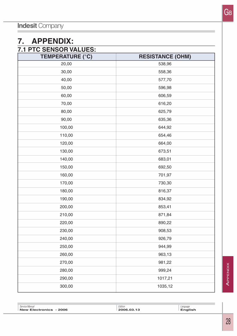
7. APPENDIX:
TEMPERATURE (°C) RESISTANCE (OHM) 20,00 538,96
30,00 558,36
40,00 577,70
50,00 596,98
60,00 606,59
70,00 616,20
80,00 625,79
90,00 635,36
100,00 644,92
110,00 654,46
120,00 664,00
130,00 673,51
140,00 683,01
150,00 692,50
160,00 701,97
170,00 730,30
180,00 816,37
190,00 834,92
200,00 853,41
210,00 871,84
220,00 890,22
230,00 908,53
240,00 926,79
250,00 944,99
260,00 963,13
270,00 981,22
280,00 999,24
290,00 1017,21
300,00 1035,12
7.1 PTC SENSOR VALUES:
AP
PE
ND
IX
GB
29
LanguageEnglish
Service ManualNew Electronics - 2006
Edition2006.03.13
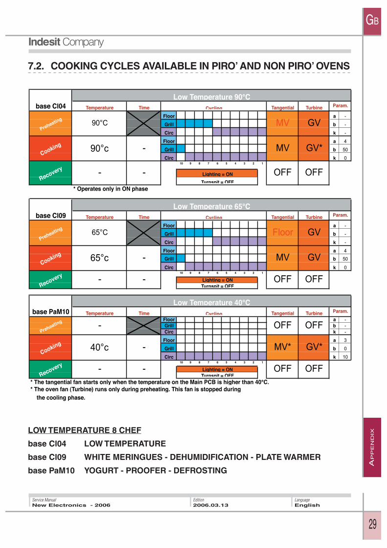
7.2. COOKING CYCLES AVAILABLE IN PIRO’ AND NON PIRO’ OVENS
base Cl04 Temperature Time Tangential Turbine
Floor a -
Grill b -
Circ k -
Floor a 4
Grill b 50
Circ k 010 9 8 7 6 5 4 3 2 1
* Operates only in ON phase
base Cl09 Temperature Time Tangential Turbine
Floor a -
Grill b -
Circ k -
Floor a 4
Grill b 50
Circ k 010 9 8 7 6 5 4 3 2 1
base PaM10 Temperature Time Tangential TurbineFloor a -
Grill b -
Circ k -
Floor a 3
Grill b 0
Circ k 1010 9 8 7 6 5 4 3 2 1
* The tangential fan starts only when the temperature on the Main PCB is higher than 40°C. * The oven fan (Turbine) runs only during preheating. This fan is stopped during the cooling phase.
Low Temperature 65°C
OFFOFFLighting = ON
Turnspit = OFF
Cycling Param.
Low Temperature 40°C
OFF
Cycling Param.
GV
GV
OFF
MV*
OFF
Recovery - -
Low Temperature 90°CCycling Param.
Preheating90°C MV
Cooking 90°c - MV GV*
GV
GV*
Preheating- OFF
Cooking 40°c -
Recovery - - OFFLighting = ONTurnspit = OFF
Preheating65°C Floor
Cooking 65°c - MV
Recovery - - OFFLighting = ONTurnspit = OFF
LOW TEMPERATURE 8 CHEF
base Cl04 LOW TEMPERATURE
base Cl09 WHITE MERINGUES - DEHUMIDIFICATION - PLATE WARMER
base PaM10 YOGURT - PROOFER - DEFROSTING
AP
PE
ND
IX
GB
30
LanguageEnglish
Service ManualNew Electronics - 2006
Edition2006.03.13
7.2.1. COOKING CYCLES AVAILABLE IN PIRO’ AND NON PIRO’ OVENS
Cl13 This function is used for obtaining Class A power consumption
Cl09Temperature Time Tangential Turbine
Base a -
Grill b -
Circ k -
Base a 4
Grill b 50
Circ k 010 9 8 7 6 5 4 3 2 1
* Medium speed is maintained for the first 12 minutes after start-up, then the tangential fan switches to max. speed
Cl13Temperature Time Tangential Turbine
Floor a -
Grill b -
Circ k -
Floor a 3
Grill b 30
Circ k 1510 9 8 7 6 5 4 3 2 1
* Medium speed is maintained for the first 12 minutes after start-up, then the tangential fan switches to max. speed
ViM07% power Time Tangential Turbine
Floor a -
Grill b -
Circ k -
Floor a -
Grill b -
Circ k -10 9 8 7 6 5 4 3 2 1
OFFLighting = ONTurnspit = ON
Cooking 100%5% - 100%
Recovery - - OFF
-
OFF
GV
TURNSPIT GRILL PyroCycling Param.
OFF
OFF
210 40 -
250
Preheating-
- GV
Recovery - - OFF OFFLighting = ON
Turnspit = ON
Cooking
Multilevels 40°-250° 2R PyroCycling Param.
GV
Cooking 20040 - 250
- GV GV
Preheating190 MV*
Recovery - - OFF OFFLighting = ONTurnspit = OFF
BROWNING 40°-250° PyroCycling Param.
Preheating200 MV* GV
GV

AP
PE
ND
IX
GB
31
LanguageEnglish
Service ManualNew Electronics - 2006
Edition2006.03.13
7.2.2. COOKING CYCLES AVAILABLE IN PIRO’ AND NON PIRO’ OVENS
base ViA02 Temperature Time Tangential Turbine
Floor a -
Grill b -
Circ k -
Floor a 3
Grill b 0
Circ k 10
Floor a 3
Grill b 0
Circ k 10
Floor a 3
Grill b 0
Circ k 1010 9 8 7 6 5 4 3 2 1
* The duration of phase 3 is variable by +/- 10mn, the total duration will therefore be 70mn +/- 10mn
Temperature Time Tangential Turbine
Floor a 0
Grill b 100
Circ k 0
Floor a 4
Grill b 50
Circ k 0
Floor a 4
Grill b 50
Circ k 0
* When function is started: If Oven Temp. < 120°C -->, Cooking time 35'
If Oven Temp. > 120°C -->, Cooking time 30'
** The duration of the recovery phase depends on the time employed in the preheating phase to bring the oven
up to the preset temperature, and on the cooking time.
The total duration of the cooking cycle will always be 45', including preheating.
Param.
GV
GV
OFF
Lighting = ON
Turnspit = OFF
CAKES Automatic 2R PyroCycling
Recovery 50
No change10' PV
GV
Cooking 160 No
change50'* PV GV
Cooking 235 No
change10' PV
VEAL ROAST AUTO PyroCycling Param.
Preheating 210 No
changePV GV
Cooking 190 No
change
35' *
30'MV
Preheating Turnspit =
OFFMV
OFF
Lighting = ON
Turnspit = OFF
Recovery 50 No
change
10' **
15'MV

AP
PE
ND
IX
GB
32
LanguageEnglish
Service ManualNew Electronics - 2006
Edition2006.03.13
7.2.3. COOKING CYCLES AVAILABLE IN D.L. PIRO’ AND NON PIRO’ OVENS
base Pai01 Temperature Time Tangential Turbine
Floor a 3
Grill b 35
Circ k 0
Floor a 0
Grill b 100
Circ k 0
Floor a 3
Grill b 35
Circ k 0
Floor a 4
Grill b 50
Circ k 0
Floor a 3
Grill b 35
Circ k 010 9 8 7 6 5 4 3 2 1
* the oven must be equipped with two drip trays, one for the bread and the other for the water close to the grillThe duration of the cycle is 50 minutes
base Piz03 Temperature Time Tangential Turbine
Floor a -
Grill b -
Circ k -
Floor a 4
Grill b 50
Circ k 010 9 8 7 6 5 4 3 2 1
* The duration of phase 2 is variable by +/- 5mn, the total duration will therefore be 28mn +/- 5mn
GVLighting = ON
Turnspit = OFF
Phase 5 210
No change
Phase 6 - 5' MV
GV
Phase 3 100
No change
GV
Phase 1 60 No
change
10' MV
Phase 4 220
No change15' MV
Phase 2 100
No change- MV
10' MV
GV
GV
GV
10' MV
BREAD Automatic 2R Pyro *Cycling Param.
Phase 1 220
No change- MV
25'* MV
PIZZA AUTO cold oven 2R PyroCycling Param.
GV
Lighting = ON
Turnspit = OFF
GV
Phase 3 - 3' MV OFF
Phase 2 180
No change

AP
PE
ND
IX
GB
33
LanguageEnglish
Service ManualNew Electronics - 2006
Edition2006.03.13
7.2.4. COOKING CYCLES AVAILABLE IN D. L. PIRO’ AND NON PIRO’ OVENS Note: the D.L. ovens feature two confi gurations: “Comfort” more cycles, “Standard2 less cycles.
base Cl09 Temperature Time Tangential Turbine
Floor a -
Grill b -
Circ k -
Floor a 4
Grill b 50
Circ k 010 9 8 7 6 5 4 3 2 1
* the speed of the tangential fan in preheating is low until the oven reaches 160°cAbove 160°C the tangential fan runs at medium speed
GV
Recovery - - OFF OFFLighting = ONTurnspit = OFF
Cooking 20030 - 300
MULTILEVELS 30°-300° F48-2R PyroCycling Param.
GVPreheating
190 PV*
- MV
base Cl13 Temperature Time Tangential Turbine
Floor a -
Grill b -
Circ k -
Floor a 4
Grill b 50
Circ k 010 9 8 7 6 5 4 3 2 1
Preheating200 MV
MV
BROWNING 40°-250° F48-2R PyroCycling Param.
GV
GV
OFFLighting = ON
Turnspit = OFF
Cooking
Recovery - - OFF
210 40 -
250-
ViM06Temperature Time Tangential Turbine
Floor a -
Grill b -
Circ k -
Floor a 3
Grill b 50
Circ k 010 9 8 7 6 5 4 3 2 1
BARBECUE PyroCycling Param.
OFF
Cooking 300 30 -
300- MV OFF
Preheating- OFF
Recovery - - OFF OFFLighting = ONTurnspit = OFF
base ViM04 Temperature Time Tangential Turbine
Floor a -
Grill b -
Circ k -
Floor a 4
Grill b 50
Circ k 010 9 8 7 6 5 4 3 2 1
TURNSPIT F48-2R Pyro
Preheating230 PV
MV
Cycling Param.
GV
OFF
OFFLighting = ONTurnspit = ON
Cooking 27030 - 300
Recovery - - OFF
-

AP
PE
ND
IX
GB
34
LanguageEnglish
Service ManualNew Electronics - 2006
Edition2006.03.13
base Cl13 Temperature Time Tangential Turbine
Floor a -
Grill b -
Circ k -
Floor a 4
Grill b 50
Circ k 010 9 8 7 6 5 4 3 2 1
Cl04Temperature Time Tangential Turbine
Floor a -
Grill b -
Circ k -
Floor a 4
Grill b 50
Circ k 010 9 8 7 6 5 4 3 2 1
* Functions exclusively in ON phase with circular heating element active
Preheating200 MV
MV
BROWNING 40°-250° F48-2R PyroCycling Param.
GV
GV
OFFLighting = ON
Turnspit = OFF
Cooking
Recovery - - OFF
210 40 -
250-
Preheating180 PV
MV
TRADITIONAL 40°-250° 2R PyroCycling Param.
GV
GV*
OFFLighting = ON
Turnspit = OFF
Cooking 190 40 -
250
Recovery - - OFF
-
Cl04Temperature Time Tangential Turbine
Floor a -
Grill b -
Circ k -
Floor a 4
Grill b 50
Circ k 010 9 8 7 6 5 4 3 2 1
* Functions exclusively in ON phase with circular heating element active
base ViM01 Temperature Time Tangential Turbine
Floor a -
Grill b -
Circ k -
Floor a 4
Grill b 50
Circ k 010 9 8 7 6 5 4 3 2 1
Preheating180 PV
MV
TRADITIONAL 40°-250° 2R PyroCycling Param.
GV
GV*
OFFLighting = ON
Turnspit = OFF
Cooking 190 40 -
250
Recovery - - OFF
-
Preheating- OFF
PV t<50m MV t>50m
ROTISSERIE F48-2R PyroCycling Param.
OFF
GV
OFFLighting = ONTurnspit = OFF
Cooking 210 30 -
300
Recovery - - OFF
-

AP
PE
ND
IX
GB
35
LanguageEnglish
Service ManualNew Electronics - 2006
Edition2006.03.13
base ViM01 Temperature Time Tangential Turbine
Floor a -
Grill b -
Circ k -
Floor a 4
Grill b 50
Circ k 010 9 8 7 6 5 4 3 2 1
Preheating- OFF
PV t<50m MV t>50m
ROTISSERIE F48-2R PyroCycling Param.
OFF
GV
OFFLighting = ONTurnspit = OFF
Cooking 210 30 -
300
Recovery - - OFF
-
base Cl09 Temperature Time Tangential Turbine
Floor a -
Grill b -
Circ k -
Floor a 4
Grill b 50
Circ k 010 9 8 7 6 5 4 3 2 1
base Cl09 Temperature Time Tangential Turbine
Floor a -
Grill b -
Circ k -
Floor a 4
Grill b 50
Circ k 010 9 8 7 6 5 4 3 2 1
base Cl09 Temperature Time Tangential Turbine
Floor a -
Grill b -
Circ k -
Floor a 4
Grill b 50
Circ k 010 9 8 7 6 5 4 3 2 1
Preheating160 PV*
MV
Above 160°C the Tangential runs at medium speedCycling Param.
GV
GV
OFFLighting = ONTurnspit = OFF
Cooking 180140 - 220
OFF - - Recover
-
Preheating- OFF
MV
MERINGUES F48-2R PyroCycling Param.
OFF
GV
OFFLighting = ONTurnspit = OFF
Cooking 70 nochange
Recovery - - OFF
-
Preheating- OFF
MV
BROWN MERINGUES F48-2R PyroCycling Param.
OFF
GV
OFFLighting = ONTurnspit = OFF
Cooking 110
no change
Recovery - - OFF
-
AP
PE
ND
IX
GB
36
LanguageEnglish
Service ManualNew Electronics - 2006
Edition2006.03.13
Rec01Temperature Time Tangential Turbine
Floor a -
Grill b -
Circ k -
Floor a 0
Grill b 0
Circ k 010 9 8 7 6 5 4 3 2 1
* The Tangential starts only when the temperature on the Main PCB is higher than 40°C.
Temperature Time Tangential Turbine
Floor a -
Grill b -
Circ k -
Floor a 4
Grill b 35
Circ k 010 9 8 7 6 5 4 3 2 1
Temperature Time Tangential Turbine
Floor a -
Grill b -
Circ k -
Floor a 4
Grill b 35
Circ k 010 9 8 7 6 5 4 3 2 1
Preheating- OFF
MV*
DEFROSTINGCycling Param.
OFF
GV
OFFLighting = ONTurnspit = OFF
Cooking -
Recovery - - OFF
-
PreheatingPV GV
65 no
change
LOW TEMPERATURE COOKING 85°C F48-2R PyroCycling Param.
GV
OFFLighting = ONTurnspit = OFF
85 no
change
- - OFF
- PVCooking
Preheating 75 no
change
Recovery
PV
- PV
LOW TEMPERATURE COOKING 95°C F48-2R PyroCycling Param.
GV
GV
OFFLighting = ONTurnspit = OFF
Cooking 95 no
change
Recovery - - OFF
Temperature Time Tangential Turbine
Floor a -
Grill b -
Circ k -
Floor a 4
Grill b 50
Circ k 010 9 8 7 6 5 4 3 2 1
GV
LOW TEMPERATURE COOKING 120°C F48-2R PyroCycling Param.
GVPreheating 100 no
changePV
Cooking 120 no
change- PV
Recovery - - OFF OFFLighting = ONTurnspit = OFF
AP
PE
ND
IX
GB
37
LanguageEnglish
Service ManualNew Electronics - 2006
Edition2006.03.13
Temperature Time Tangential Turbine
Floor a -
Grill b -
Circ k -
Floor a 4
Grill b 50
Circ k 010 9 8 7 6 5 4 3 2 1
Temperature Time Tangential Param.
Floor a -
Grill b -
Circ k -
Floor a 4
Grill b 50
Circ k 010 9 8 7 6 5 4 3 2 1
Cooking 140 no
change- PV
PREPARATORY HEATING F48-2R PyroCycling Turbine
Preheating
Cooking 110 90-
130
140 no
changePV GV
GV
Recovery
Turnspit = OFF- - OFF OFFLighting = ON
PASTEURISATION F48-2R PyroCycling Param.
GV
- PV
Preheating 90 no
changePV
GV
Recovery - - OFF OFFLighting = ONTurnspit = OFF

AP
PE
ND
IX
GB
38
LanguageEnglish
Service ManualNew Electronics - 2006
Edition2006.03.13
SUCCESS FUNCTIONSAs for the current Scholtes Lev. 6, always request confirmation when executing automatic programmes
As for the current Scholtes Lev. 6, when executing automatic programmes always request confirmation
automatic cooking times.
Important, write the following on the handbook: WHEN PERFORMING AUTOMATIC COOKING PROGRAMMES DO NOT OPEN
THE OVEN DOOR TO AVOID INTERFERING WITH COOKING TIMES AND TEMPERATURES.
base ViA01 Temperature Time Tangential Turbine
Floor a -
Grill b -
Circ k -
Floor a 4
Grill b 50
Circ k 0
Floor a 4
Grill b 50
Circ k 0
Floor a 4
Grill b 50
Circ k 010 9 8 7 6 5 4 3 2 1
* The total duration of the cooking cycle including browning will be 55' ±20'
(the ±20' tolerance in cooking time duration will always impact on "Cooking 2")** The duration in the recovery phase depends on the time employed in the preheating phase to bring the oven
up to the required temperature.
base ViA02 Temperature Time Tangential Turbine
Floor a -
Grill b -
Circ k -
Floor a 4
Grill b 50
Circ k 0
Floor a 4
Grill b 50
Circ k 0
Floor a 4
Grill b 50
Circ k 010 9 8 7 6 5 4 3 2 1
up to the required temperature.
* The duration of the recovery phase depends on the time employed in the preheating phase to bring the oven
The total duration of the cooking cycle will always be 70'.
OFF
Lighting = ON
Turnspit = OFF
GV
Cooking 2 160 no
change50' PV GV
Cooking 1 235 no
change10' PV
Cycling Param.
Preheating 210 no
changePV GV
OFF
Lighting = ON
Turnspit = OFF
VEAL ROAST AUTO 2R Pyro
Recovery 50 no
change10'** PV
GV
Cooking 2 160 no
change35'* PV GV
Cooking 1 235 no
change10' PV
Preheating 210 no
changePV GV
BEEF ROAST AUTO 2R PyroCycling Param.
Recovery 50 no
change10'* PV
AP
PE
ND
IX
GB
39
LanguageEnglish
Service ManualNew Electronics - 2006
Edition2006.03.13
base ViA03 Temperature Time Tangential Turbine
Floor a -
Grill b -
Circ k -
Floor a 4
Grill b 50
Circ k 0
Floor a 4
Grill b 50
Circ k 0
Floor a 4
Grill b 50
Circ k 010 9 8 7 6 5 4 3 2 1
* The duration of the recovery phase depends on the time employed in the preheating phase to bring the oven
up to the required temperature.
The total duration of the cooking cycle will always be 90'.
base ViA04 Temperature Time Tangential Turbine
Floor a -
Grill b -
Circ k -
Floor a 4
Grill b 50
Circ k 0
Floor a 4
Grill b 50
Circ k 010 9 8 7 6 5 4 3 2 1
* The duration of the recovery phase depends on the time employed in the preheating phase to bring the oven
up to the preset temperature.
The total duration of the cooking cycle will always be 65'.
Cycling Param.
GV
OFF
Lighting = ON
Turnspit = OFF
GV
PORK ROAST AUTO 2R Pyro
10'* PV
Cooking 2 160 nochange 70' PV
Recovery 50 nochange
GV
Preheating 210 nochange PV
Cooking 1 235 nochange 10' PV
ROAST CHICKEN AUTO 2R PyroCycling Param.
Preheating 230 nochange PV GV
GVCooking 205
no change 55' PV
Recovery 50no change 10'* PV OFF
Lighting = ON
Turnspit = OFF

AP
PE
ND
IX
GB
40
LanguageEnglish
Service ManualNew Electronics - 2006
Edition2006.03.13
base ViA05 Temperature Time Tangential Turbine
Floor a -
Grill b -
Circ k -
Floor a 4
Grill b 50
Circ k 0
Floor a 4
Grill b 50
Circ k 0
Floor a 4
Grill b 50
Circ k 010 9 8 7 6 5 4 3 2 1
* The total duration of the cooking cycle including browning will be 70' ±25'
(the ±25' tolerance in cooking time duration will always impact on "Cooking 2")** The duration in the recovery phase depends on the time employed in the preheating phase to bring the oven
up to the preset temperature.
Temperature Time Tangential Turbine
Floor a -
Grill b 100
Circ k -
Floor a 4
Grill b 50
Circ k 0
Floor a 4
Grill b 50
Circ k 0
* When function is started: If Oven Temp. < 120°C -->Preheating 210°C, Cooking 220°C
If Oven Temp. > 120°C -->Preheating 200°C, Cooking 210°C
** The duration of the recovery phase depends on the time employed in the preheating phase to bring the oven
up to the preset temperature.
The total duration of the cooking cycle will always be 45', including preheating.
OK for one shelf with hot or cold oven and on two shelves (L2 and L4) exclusively with cold oven
Turnspit = OFF
OFF
Lighting = ON
GV
Recovery 50 no
change10'** MV
Cooking 210-220*no change 35' MV
Cycling Param.
Preheating 200-210*no change MV GV
LEG OF LAMB 2R PyroCycling Param.
Preheating 210no change PV GV
GV
Cooking 2 160no change 50'* PV GV
Cooking 1 235no change 10' PV
Recovery 50no change 10'** PV OFF
Lighting = ON
Turnspit = OFF
TARTS AUTO 2R Pyro

AP
PE
ND
IX
GB
41
LanguageEnglish
Service ManualNew Electronics - 2006
Edition2006.03.13
Temperature Time Tangential Turbine
Floor a 0
Grill b 100
Circ k 0
Floor a 4
Grill b 50
Circ k 10
Floor a 4
Grill b 50
Circ k 1010 9 8 7 6 5 4 3 2 1
* When function is started: If Oven Temp. < 120°C -->Preheating 180°C, Cooking duration 25'
If Oven Temp. > 120°C -->Preheating 175°C, Duration 20'
** The duration of the recovery phase depends on the time employed in the preheating phase to bring the oven
up to the preset temperature, and on the cooking time.
The total duration of the cooking cycle will always be 40', including preheating.
Temperature Time Tangential Turbine
Floor a 0
Grill b 100
Circ k 0
Floor a 4
Grill b 50
Circ k 0
Floor a 4
Grill b 50
Circ k 0
* When function is started: If Oven Temp. < 120°C -->Cooking time 35'
If Oven Temp. > 120°C -->, Duration 30'
** The duration of the recovery phase depends on the time employed in the preheating phase to bring the oven
up to the preset temperature, and on the cooking time.
The total duration of the cooking cycle will always be 45', including preheating.
CROISSANTS AUTO 2R PyroCycling Param.
Preheating 120 no
changePV GV
GV
Recovery 50 no
change
15'**
20'PV OFF
Cooking 180-175*no change
25'*
20'PV
Lighting = ON
Turnspit = OFF
CAKES Automatic 2R PyroCycling Param.
GV
Cooking 190 no
change
35' *
30'MV GV
Preheating 120 no
changeMV
Recovery 50 no
change
10' **
15'MV OFF
Lighting = ON
Turnspit = OFF

AP
PE
ND
IX
GB
42
LanguageEnglish
Service ManualNew Electronics - 2006
Edition2006.03.13
base PaA03 Temperature Time Tangential Turbine
Floor a 0
Grill b 100
Circ k 0
Floor a 4
Grill b 50
Circ k 0
Floor a 4
Grill b 50
Circ k 010 9 8 7 6 5 4 3 2 1
* When function is started: If Oven Temp. < 120°C -->, Cooking time 180°C
If Oven Temp. > 120°C -->, Cooking 175°C
** The duration of the recovery phase depends on the time employed in the preheating phase to bring the oven
up to the preset temperature, and on the cooking time.
The total duration of the cooking cycle will always be 65', including preheating.
base Piz03 Temperature Time Tangential Turbine
Floor a -
Grill b -
Circ k -
Floor a 4
Grill b 50
Circ k 010 9 8 7 6 5 4 3 2 1
* The duration of phase 2 is variable by +/- 5mn, the total duration will therefore be 28mn +/- 5mnCooking on one shelf, level 2 on drip tray
Phase 2 180 no
change25'* MV
Phase 3 - 3' MV
Cycling Param.
Phase 1 220 no
change- MV GV
PIZZA AUTO cold oven 2R Pyro
GV
OFFLighting = ON
Turnspit = OFF
PLUM-CAKES Automatic 2R Pyro
Preheating 120 no
changePV
50' PV
Cycling Param.
GV
Lighting = ON
Turnspit = OFF
GV
Recovery 160 no
change15' PV OFF
Cooking 180-175*no change

AP
PE
ND
IX
GB
43
LanguageEnglish
Service ManualNew Electronics - 2006
Edition2006.03.13
Temperature Time Tangential Turbine
Floor a 0
Grill b 100
Circ k 0
315 a 10
Grill b 50
Circ k 0
Floor a 10
Grill b 50
Circ k 0
Floor a 10
Grill b 50
Circ k 010 9 8 7 6 5 4 3 2 1
Phase 1: "Preheating of stone" (must be indicated on oven display as on current Lev. 6)When temperature is reached programme goes toPhase 2: "Oven loading confirmation" (maintains temperature on stone, continuous beep to warn user
that it is time to load the pizza, must be shown on display as on current Lev.6)Oven loading confirmed, go to Phase 3: "Cooking in progress" (pizza cooked, on Lev. 6 oven duration 3 minutes, must be indicated on
display as on current Lev.6)When cooking is terminated oven switches to Phase 4: Browning in progress" (once surface cooking of pizza has been performed, continuous beep to
remind the user to extract the pizza as soon as the surface cooking is considered to be sufficient, must be indicated on the display)
The user opens the oven door to remove the pizza. As soon as the door is closed the oven returns to Phase 1 and the cycle restarts so that another pizza can be cooked.
* Cooking 1 shelf level 3 on stonepreheating time approx. 32 mncooking time, mini = 3mn, maxi = 4mnstone heating time = approx. 4mn
Cycling Param.
GV
GV
GV
GV
PIZZERIA 2R *
Phase 1 310
no changePV
Phase 3 315 no
change3' MV
Phase 2 315 no
change- PV
OFFLighting = ONTurnspit = OFFRecovery - - OFF
Phase 4 315
no change- MV
AP
PE
ND
IX
GB
44
LanguageEnglish
Service ManualNew Electronics - 2006
Edition2006.03.13
Temperature Time Tangential Turbine
Floor a 3
Grill b 35
Circ k 0
Floor a 0
Grill b 100
Circ k 0
Floor a 3
Grill b 35
Circ k 0
Floor a 4
Grill b 50
Circ k 0
Floor a 3
Grill b 35
Circ k 010 9 8 7 6 5 4 3 2 1
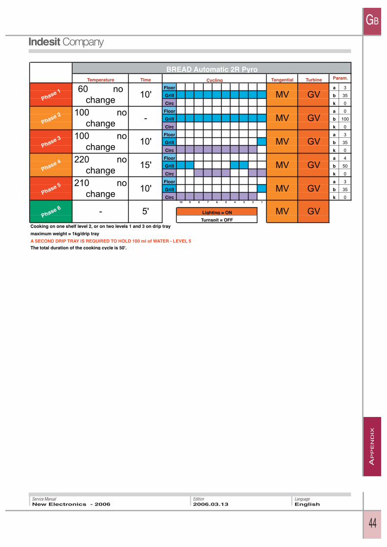
Cooking on one shelf level 2, or on two levels 1 and 3 on drip tray
maximum weight = 1kg/drip tray
A SECOND DRIP TRAY IS REQUIRED TO HOLD 100 ml of WATER - LEVEL 5The total duration of the cooking cycle is 50'.
GV
Phase 6 - 5' MV GVLighting = ON
Turnspit = OFF
Phase 5 210 no
change10' MV
GV
Phase 4 220 no
change15' MV GV
Phase 3 100 no
change10' MV
GV
Phase 2 100 no
change- MV GV
Phase 1 60 no
change10' MV
BREAD Automatic 2R PyroCycling Param.

GB
Indesit Companyviale Aristide Merloni, 4760044 Fabriano - Italytel. +39 0732 66 11 - telex 560196 - fax +39 0732 66 2954 - www.indesitcompany.com
LanguageEnglish
Service ManualNew Electronics - 2006
Edition2006.03.13