service manual - · pdf fileservice manual model: wst12mc16s ... it is an important part of...
TRANSCRIPT
Willis Air Conditioning
Service Manual
MODEL: WST12MC16SWST09MH16SWST12MH16S
Summary and features..................................................................................1
Part 1 Safety Precautions..........................................................................................2
Part 2 Specifications.....................................................................................................3
2.1 Unit Specifications..................................................................................................3
2.3 CapacityVariation Ratio AccordingtoTemperature...............................................152.2 Operation Characteristic Curve............................................................................15
2.4 Operation Date.....................................................................................................162.5 Noise criteria curve tables for both models..........................................................16
Part 3 Construction Views......................................................................................17
3.1 Indoor Unit ...........................................................................................................173.2 Outdoor Unit ........................................................................................................17
Part 4 Refrigerant System Diagram...................................................................18
5.1 Electrical Data......................................................................................................195.2 Electrical Wiring....................................................................................................195.2 Printed Circuit Board ............................................................................................21
Part 5 Schematic Diagram......................................................................................19
6.1 Remote Control Operations..................................................................................266.2 Changing Batteries and Notices ..........................................................................286.3 Description of Each Control Operation.................................................................286.4 Unit ON/OFF button..............................................................................................28
Part 6 Function and Control...................................................................................26
Part 7 Installation Manual........................................................................................36
7.1 Installation Dimension Diagram............................................................................36
7.5 Test Operation......................................................................................................41
7.2 Installation Position Selection..............................................................................367.3 Installation of Indoor Unit......................................................................................367.4 Installation of Outdoor Unit...................................................................................40
Table of Contents

Part 8 Exploded Views and Parts List..............................................................42
Part 9 Troubleshooting...............................................................................................57
9.1 Precautions Before Performing Inspection or Repair...........................................579.2 Confirmation.........................................................................................................579.3 Judgement by Flashing LED of Indoor/Outdoor Unit...........................................579.4 How to Check Simply the Main Part.....................................................................599.5 2-way, 3-way Valve Appearance..........................................................................63
8.1 Indoor unit.............................................................................................................42
8.2 Outdoor unit..........................................................................................................49
Part10 Removal Procedure.......................................................................................70
10.1 Removal Procedure of Indoor Unit.....................................................................70
10.2 Removal Procedure of Outdoor Unit...................................................................84
Part11 Care and Cleaning..........................................................................................89
11.1 ................................................................................89
11.2 ................................................................................89
Table of Contents
Cleaning of cooling system
Cleaning of heat exchanger

1
Summary and featuresIndoor Unit
Remote control window
YB1F2F
Summary and features
WST12MC16SWST09MH16SWST12MH16S
Outdoor Unit
WST12MC16SWST09MH16SWST12MH16S
FAN AUTOOPER
HEALTHAIR
FILTERTURBO
ON/OFF
X-FAN
HOUR
HUMIDITY
ON/OFF MODE
FAN
X-FAN
TURBO
TEMP TIMER
SLEEP LIGHT

2
1.Safety Precautions
Safety Precautions
Important!
This air conditioning system meets strict safety andoperating standards. As the installer or service person,it is an important part of your job to install or service thesystem so it operates safely and efficiently.
Follow each installation or repair step exactly as shown.Observe all local, state, and national electrical codes.Pay close attention to all warning and caution noticesgiven in this manual.
To prevent injury to the user or other people andproperty damage, the following instructions mustbe followed.
About the pictures:Erroneous handing gives a high possi-bility to induce serious results such asdeath or heavy injury.
Erroneous handing may induce seriousinjury depending on the situation.
Do not supply power to the unit until all wiring and tubingare completed or reconnected and checked.Highly dangerous electrical voltages are used in thissystem. Carefully refer to the wiring diagram and theseinstructions when wiring. Improper connections and inad-equate grounding can cause accidental injury or death.Ground the unit following local electrical codes.Connect all wiring tightly. Loose wiring may cause over-heating at connection points and a possible fire hazard.
All electric work must be performed by licensed technician, ac-cording to local regulations and the instructions given in thismanual.
There is risk of fire, electric shock, explosion, or injury.
Ask your dealer or specialized subcontractor for installation orrepair work.
Make sure the ceiling/wall is strong enough to hold theunit’s weight. The outdoor unit should be installed in alocation where air and noise emitted by the unit will notdisturb the neighbors.Properly insulate any tubing run inside a room to prevent"sweating" that can cause dripping and water damage towalls and floors.The outdoor unit must be installed on stable, level surface,in a place where there is no accumulation of snow, leaves
or rubbish.The unit should be installed according to the instructionsin order to minimize the risk of damage from earthquakes,typhoons or strong winds.When the refrigerant touches the fire etc., it was decomposedand a poisonous gas is generated.Use only the specified refrigerant to charge the refrigerantcircuit.Do not mix it with any other refrigerant and do not allow air toremain in the circuit.Air enclosed in the circuit can cause high pressure resultingin a rupture and other hazards.After completing installation work, make sure that refriger-ant gas has not leaked.The limit density is made not to be exceeded even if the refrig-erant leaks by any chance.Turn the power off at the main power box (mains) before open-ing the unit to check or repair electrical parts and wiring.Keep your fingers and clothing away from any moving parts.Clean up the site after you finish, remembering to check thatno metal scraps or bits of wiring have been left inside the unitbeing serviced.The unit must be properly earth connected.
Caution
Warning
Warning
Caution
Never install on the place where a combustible gas mightleak. The gas may ignite or explode when the gas leaks andcollects in surround of the unit.When the unit is installed at telecommunication centers orhospitals, take a proper provision against noise.When installing at a watery place, provide an electric leakbreaker.Do not wash the unit with water.Be very careful about unit transportation. The unit should notbe carried by only one person if it is more than 20kg. It occasion-ally causes the damage of the unit and health to be impaired.Do not touch the heat exchanger fins with your hands.Doing so may cut your hands.Do not touch the compressor or refrigerant piping withoutwearing glove on your hands. Touching directly such part cancause a burn or frostbite as it becomes high or low temperatureaccording to the refrigerant state.Do not operate the air conditioner without the air filter setplace. Dust may accumulate, and cause a failure.At emergency (if you smell something burning), stop opera-tion and turn the power source switch off.

3
2.Specifications
2.1 Unit Specifications
Specifications

7
Specifications

13
Unit
WST12MC16S WST12MH16S
CB409002101 CB409N02100 CB409002201 CB409N02200Rated Voltage V 208~230 208~230Rated Frequency Hz 60 60Phases 1 1
outdoor outdoorBtu/h 12000(3300 12500) 12000(3300 12500)Btu/h - 12000(3400 12500)
W 1160(260 1340) 1160(260 1340)W - 950(260 1000)A 5.48 5.48A - 4.35W 1340 1340A 5.94 5.94
m3/h 580 580L/h 1.4 1.4
Btu/w.h 10.34 10.34Btu/w.h - 12.63Btu/w.h 16.00 16.00Btu/w.h - 8.50
m2 16-24 16-24Model of indoor unit WST12MC16S WST12MH16SFan Type Cross-flow Cross-flowDiameter Length(DXL) mm 92X595.5 92X595.5Fan Motor Cooling Speed(SH/H/M/L)
r/min 1350/1150/950/750 1350/1150/950/750
Fan Motor Heating Speed(SH/H/M/L) r/min - 1350/1200/100/850
Output of Fan Motor W 15 15Fan Motor RLA A 0.19 0.19Fan Motor Capacitor F 1.2 1.2Input of Heater W - -Evaporator Form Aluminum Fin-copper Tube Aluminum Fin-copper TubePipe Diameter mm 7 7Row-fin Gap mm 2-1.4 2-1.4Coil Length (LXDXW) mm 610X24X294 610X24X294Swing Motor Model MP24BA MP24BAOutput of Swing Motor W 1.5 1.5Fuse A PCB3.15A PCB3.15ASound Pressure Level(SH/H/M/L)
dB (A) 44/39/33/28 44/39/33/28
Sound Power Level (SH/H/M/L) dB (A) 54/49/43/38 54/49/43/38Dimension (WXHXD) mm 770X283X201 770X283X201Dimension of Carton Box(L/W/H)
mm 844X261X342 844X261X342
Dimension of Package (L/W/H) mm 847X264X357 847X264X357Net Weight kg 9 9Gross Weight kg 12 12
IndoorUnit
Value
COPSEERHSPFApplication Area
Rated CurrentAir Flow Volume(SH/H/M/L)Dehumidifying VolumeEER
Heating Power Input (Min Max)Cooling Power CurrentHeating Power CurrentRated Input
Power Supply ModeCooling Capacity (Min Max)Heating Capacity (Min Max)Cooling Power Input (Min Max)
Parameter
Model
Product Code
PowerSupply
Specifications

15
50
60
70
80
90
100
110
32 33 34 35 36 37 38 39 40 41 42 43 44 45 46
Cap
acity
ratio
(%)
ConditionIndoor:DB27℃ WB19℃Indoor air flow: Super HighPipe length:7.5m
Outdoor temp. (°C)
0
20
40
60
80
100
120
-15 -10 -5 0 5 10
Cap
acity
ratio
(%)
ConditionIndoor:DB20℃Indoor air flow: Super HighPipe length:7.5m
Outdoor temp. (°C)
Cooling Heating
0
1
2
3
4
5
6
7
8
9
10
0 20 40 60 80 100 120
ConditionIndoor:DB 27 WB19Indoor air flow: Super HighPipe length:7.5mVoltage:230V
Compressor Speed(rps)
0
1
2
3
4
5
6
7
8
0 20 40 60 80 100 120
ConditionIndoor:DB 20Indoor air flow: Super HighPipe length:7.5mVoltage:230V
Compressor Speed(rps)
Cooling Heating
Cur
rent
(A)
Cur
rent
(A)
2.2 Operation Characteristic Curve
2.3 Capacity Variation Ratio According to Temperature
Specifications

16
Indoor Outdoor09K 0.9 to 1.1 5312K 0.8 to 1.0 72
OutdoorFan Mode
CompressorRevolution(rps)
27/19 35/24 Super High 930rpm
Temp. Condition( )Model Standard
Pressure(Mpa)Indoor Fan
Mode
Indoor Outdoor09K 2.3 to 2.5 7212K 2.4 to 2.6 78
OutdoorFan Mode
CompressorRevolution(rps)
20/- 7/6 Super High 930rpm
Temp. Condition( )Model Standard
Pressure(Mpa)Indoor Fan
Mode
Cooling
Heating
NOTES :
(2) Connecting piping condition : 7.5 m
2.4 Operation Date
Specifications
2.5 Noise criteria curve tables for both models
40
30
20
Indoor side noise when blowing
Indoor fan motor rotating speed
Low Middle High
12K
09K
40
42
44
46
48
50
52
54
20 4030 50 60 70 80
Compressor frequency(Hz)
Noi
se d
B(A
)
Heating
CoolingNoi
se/d
B(A
)
Disacharge pressure
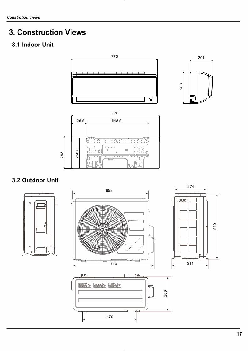
17
3. Construction Views3.1 Indoor Unit
3.2 Outdoor Unit
710
658274
550
318
470
299
Constrction views
258.
5
126.5 548.5
283
770
770 201
283

18
4. Refrigerant System Diagram
INDOOR UNIT OUTDOOR UNIT
HEATEXCHANGE(EVAPORATOR)
HEATEXCHANGE(CONDENSER)
COMPRESSOR
GAS SIDE
3-WAY VALVE
LIQUID SIDE
2-WAY VALVE
COOLINGHEATING
Accumlator
Discharge
Suction
Muffler4-Way valve
CapillaryStrainer Strainer
Refrigerant pipe diameterLiquid : 1/4" (6 mm)Gas : 3/8" (9.52 mm)
INDOOR UNIT OUTDOOR UNIT
HEATEXCHANGE(EVAPORATOR)
HEATEXCHANGE(CONDENSER)
COMPRESSOR
GAS SIDE
3-WAY VALVE
LIQUID SIDE
2-WAY VALVE
COOLING
Accumlator
Discharge
Suction
Muffler
CapillaryStrainer Strainer
(1)Cooling Only Models
(2)Cooling & Heating Models
Refrigerant System Diagram
19
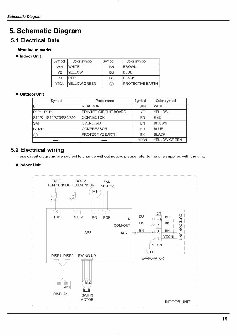
Symbol Color symbol Symbol Color symbol WH WHITE BN BROWN YE YELLOW BU BLUE RD RED BK BLACK
YEGN YELLOW GREEN PROTECTIVE EARTH
Symbol Parts name Symbol Color symbol L1 REACROR WH WHITE PCB1~PCB2 PRINTED CIRCUIT BOARD YE YELLOW S10/S11S40/S70/S80/S90 CONNECTOR RD RED SAT OVERLOAD BN BROWN COMP COMPRESSOR BU BLUE
PROTECTIVE EARTH BK BLACK YEGN YELLOW GREEN
5. Schematic Diagram5.1 Electrical Date
5.2 Electrical wiring
Outdoor Unit
These circuit diagrams are subject to change without notice, please refer to the one supplied with the unit.
Indoor Unit
Indoor Unit
Schematic Diagram
0
TUBE ROOM N
M2
N(1)
XTBU
3YEGN
2
RT1
DISP1
0RT2
BK
BN
PE
YEGN
COM-OUTBK
BN
BU
AP1
AC-L
DISP2 SWING-UD
PGF
M1
PG
MOTORFAN
TEM.SENSORROOM
TEM.SENSORTUBE
OU
TDO
OR
UN
IT
DISPLAY SWINGMOTOR INDOOR UNIT
EVAPORATOR
AP2

20
Outdoor Unit
Schematic Diagram
N(1)XT
32
BK
PE
BN
BUPCB1AC2
S
AC1
E1
E2
YEGN
PCB2
U V W
0RT3
0RT4 RT5
0
S90
S11S10
HL2
HN2HN3
HL3
L1
HR2HR1
FAN
S70
COMP.
HA1
HA2
SAT
YE
PE
S40
PE
M
OG
PEPE
BURDX1
WH
YEGN
YEGN
BU
BNBU
YEGN
WHYERD BU
YEGN
YEGN
OG
OUTDOOR UNIT
IND
OO
R U
NIT
ELECTRICAL BOX
MOTOR
SUB-ASSYCLAPBOARD
L2
L1
L2L1
U V W
POWER
S80S80
4YF4YF
21
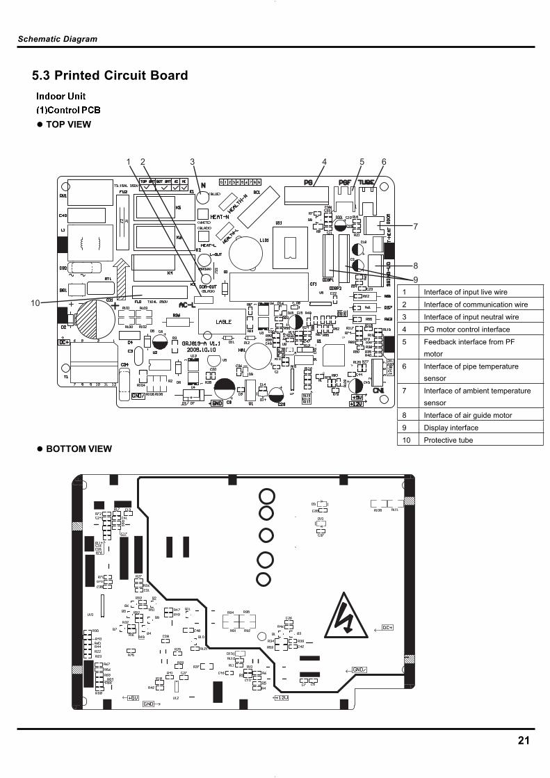
5.3 Printed Circuit Board
TOP VIEW
BOTTOM VIEW
Schematic Diagram
1 2 3 4 5 6
7
89
101 Interface of input live wire
2 Interface of communication wire
3 Interface of input neutral wire
4 PG motor control interface
5 Feedback interface from PF motor
6 Interface of pipe temperature sensor
7 Interface of ambient temperature sensor
8 Interface of air guide motor
9 Display interface
10 Protective tube
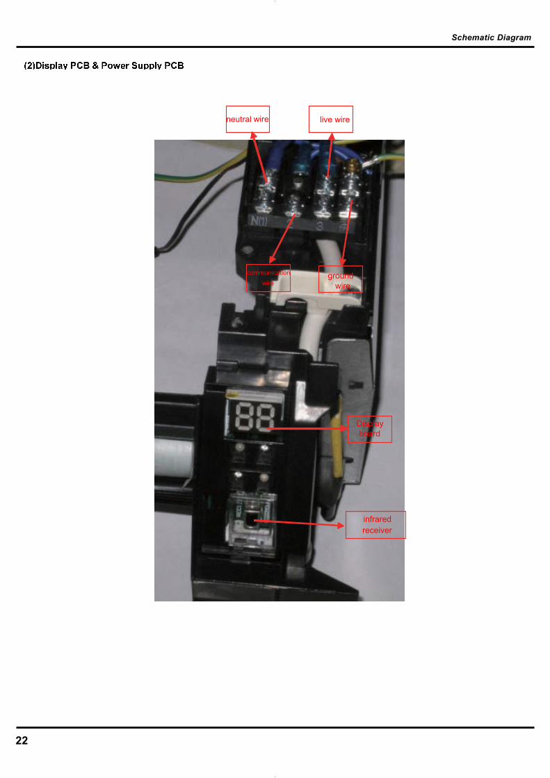
22
Schematic Diagram
wire live wire
communication wire
groundwire
Displayboard
infraredreceiver
neutral
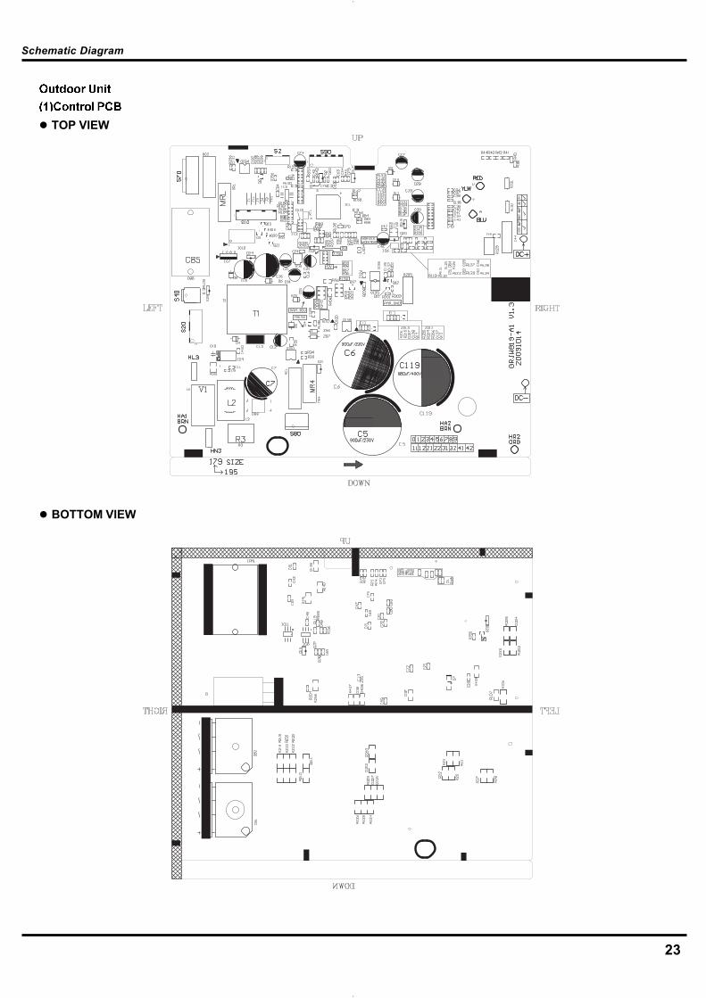
23
TOP VIEW
BOTTOM VIEW
Schematic Diagram

24
FRONT VIEW
BOTTOM VIEW
Schematic Diagram

25
TOP VIEW
BOTTOM VIEW
Schematic Diagram

26
6. Function and Control6.1 Remote Controller Description
Function and Control
Press this button to start or stop operation.ON/OFF
MODE
+
-
Press it to select operation mode(AUTO/COOL/DRY/FAN/HEAT).
: Press it to increase temperature setting.
: Press it to decrease temperature setting.
FA
HEALTH SAVE
N
Press it to set up &down swing angle.
TIMER
X-FAN(X-FAN is the alternative expression of BLOW for thepurpose of understanding.)
Press it to select health mode on or off.
TEMP
TURBO
SLEEP
LIGHT
Press it to set fan speed.
Press it set auto-on timer/auto-off timer.
1
2
7
4
3
5
6
Press it to set left & right swing angle.8
11
9
10
12
13
14
FAN AUTOOPER
HEALTHAIR
FILTERTURBO
ON/OFF
X-FAN
HOUR
HUMIDITY
ON/OFF MODE
FAN
X-FAN
TURBO
TEMP TIMER
SLEEP LIGHT
2
11
7
10
13
9
43
12
8
6
14
5
1
Press it to turn on/off the light.
Remote controller description
ON/OFF :
MODE :
1
2
Press this button to start the unit operation .Press this button again to stop the unit operation.
Each time you press this button,a mode is selected in a sequence that goes from AUTO, COOL,DRY, FAN,and HEAT*, as the following:
AUTO COOL DRY FAN HEAT *
*Note:Only for models with heating function.
After energization, AUTO mode is defaulted. In AUTO mode, the set temperature will not be displayed on the mode in accordance with the room temp
erature to make indoor room comfortable.LCD, and the unit will automatically select the suitable operation
27
Function and Control
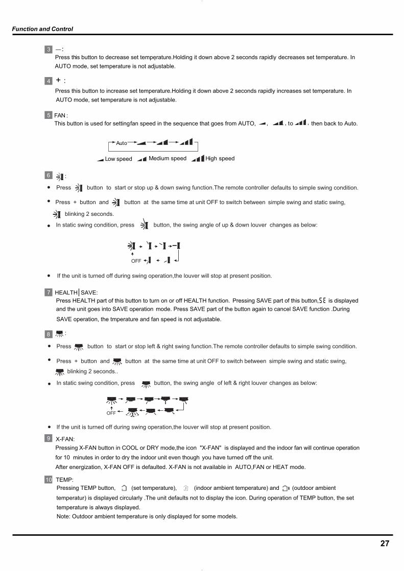
+ :
FAN :
4
3
5
Press this button to decrease set temperature.Holding it down above 2 seconds rapidly. decreases set temperature. In
Press this button to increase set temperature.Holding it down above 2 seconds rapidly increases set temperature. In
This button is used for setting fan speed in the sequence that goes from AUTO, , to then back to Auto., ,
Auto
Low speed Medium speed High speed
:6
Press button to start or stop up & down swing function.The remote controller defaults to simple swing condition.
Press + button and button at the same time at unit OFF to switch between simple swing and static swing,
blinking 2 seconds.
In static swing condition, press
If the unit is turned off during swing operation,the louver will stop at present position.
button, the swing angle of up & down louver changes as below:
●
●
●
●
AUTO mode, set temperature is not adjustable.
AUTO mode, set temperature is not adjustable.
HEALTH SAVE:Press HEALTH part of this button to turn on or off HEALTH function.
7
X-FAN:9
10 TEMP:
:8
Pressing X-FAN button in COOL or DRY mode,the icon "X-FAN" is displayed and the indoor fan will continue operation
for 10 minutes in order to dry the indoor unit even though you have turned off the unit.
After energization, X-FAN OFF is defaulted. X-FAN is not available in AUTO,FAN or HEAT mode.
Pressing TEMP button, (set temperature), (indoor ambient temperature) and (outdoor ambient
temperatur) is displayed circularly .The unit defaults not to display the icon. During operation of TEMP button, the set temperature is always displayed.Note: Outdoor ambient temperature is only displayed for some models.
Pressing SAVE part of this button, and the unit goes into SAVE operation mode. Press SAVE part of the button again to cancel SAVE function .During
SAVE operation, the tmperature and fan speed is not adjustable.
is displayed
Press + button and button at the same time at unit OFF to switch between simple swing and static swing,
Press button to start or stop left & right swing function.The remote controller defaults to simple swing condition.
blinking 2 seconds..
In static swing condition, press button, the swing angle of left & right louver changes as below:
●
●
●
If the unit is turned off during swing operation,the louver will stop at present position.●

28
Function and Control
Press TIMER button at unit ON to set TIMER OFF, HOUR OFF blinking. Press TIMER button at unit OFF to set TIMER
ON, HOUR ON blinking. In this case, pressing + or - button changes time setting. Holding down either button rapidly changes time setting (time setting range 0.5-24hours). Press TIMER button again to confirm setting, HOUR ON/OFF
stopping blink. If there is not any operation of button within 5 seconds during HOUR ON/OFF blinking, TIMER setting
TIMER:11
TURBO:12Press this button to activate / deactivate the Turbo function which enables the unit to reach the preset temperature in shortest time. In COOL mode, the unit will blow strong cooling air at super high fan speed. In HEAT mode, the unit will blow strong heating air at super high fan speed. (This function is not applicable for some models).
will be canceled.
SLEEP :
LIGHT:
13
14
Press this button to go into the SLEEP operation mode. Press it again to cancel. This function is available in COOL , HEAT (Only for models with heating function) or DRY mode to maintain the most comfortable temperature for you.
Press LIGHT button to turn on the display's light and press this button again to turn off the display's light. If the light is tunrned on, is displayed. If the light is tunrned off disappears.
Press "+ " and "-" buttons simultaneously to lock or unlock the keypad. If the remote controller is locked, is displayed.
At unit OFF, press "MODE" and " - " buttons simultaneously to switch between and . About switch between fahrenheit and cenrigrade
3 About lock :
and
In this case, pressing any button, blinks three times.
2
3 and
23
4 3
6.2 Replacement of Batteries1.Remove the battery cover plate from the rear of the remote controller. (As shown in the figure).2.Take out the old batteries.3.Insert two new AAA1.5V dry batteries, and pay attention to the polarity.4. Replace the battery cover plate.
Notes:
When replacing the batteries, do not use old or different batteries,otherwise, it may cause malfunction.If the wireless remote controller will not be used for a long time,please remove batteries to prevent damage from leaking batteries.The operation should be performed in its receiving range.It should be kept 1m away from the TV set or stereo sound sets.If the wireless remote controller does not operate normally, pleasetake the batteries out and replace them after 30 seconds. If still notoperating properly, replace the batteries. Sketch map for
replacing batteries
29
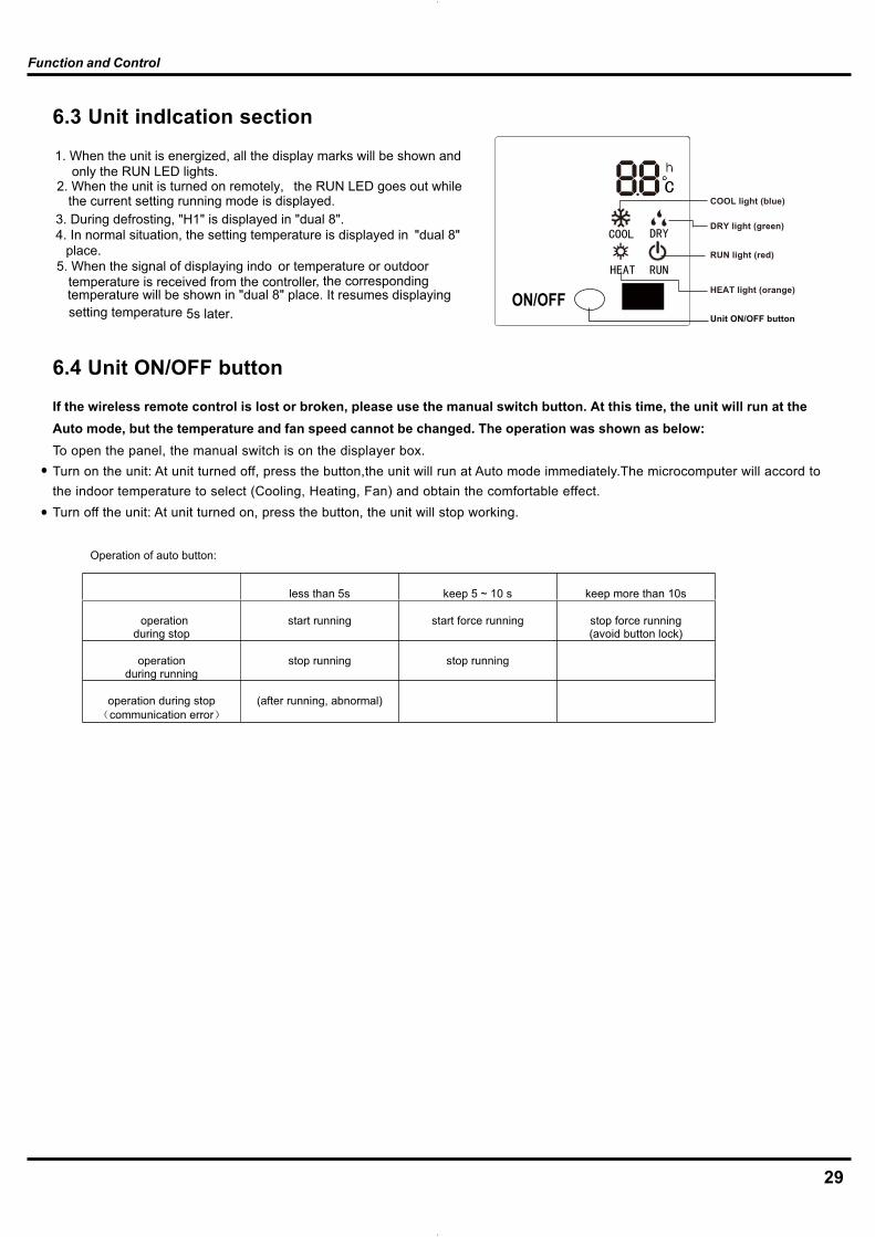
6.3 Unit indlcation section
ON/OFF
RUN light (red)
HEAT light (orange)
COOL light (blue)
DRY light (green)
Unit ON/OFF button
6.4 Unit ON/OFF button
If the wireless remote control is lost or broken, please use the manual switch button. At this time, the unit will run at theAuto mode, but the temperature and fan speed cannot be changed. The operation was shown as below:To open the panel, the manual switch is on the displayer box.Turn on the unit: At unit turned off, press the button,the unit will run at Auto mode immediately.The microcomputer will accord tothe indoor temperature to select (Cooling, Heating, Fan) and obtain the comfortable effect.Turn off the unit: At unit turned on, press the button, the unit will stop working.
Function and Control
1. When the unit is energized, all the display marks will be shown andonly the RUN LED lights.
2. When the unit is turned on remotely, the RUN LED goes out whilethe current setting running mode is displayed.
3. During defrosting, "H1" is displayed in "dual 8".4. In normal situation, the setting temperature is displayed in "dual 8"
place.5. When the signal of displaying indo or temperature or outdoor
temperature is received from the controller, the corresponding temperature will be shown in "dual 8" place. It resumes displaying setting temperature 5s later.
Operation of auto button:
less than 5s keep 5 ~ 10 s keep more than 10s
operationduring stop
start running start force running stop force running(avoid button lock)
operationduring running
stop running stop running
operation during stopcommunication error
(after running, abnormal)

Function and Control
DESCRIPTION OF EACH CONTROL OPERATION
C
B
A
C
B
A
Coolingoperation
Heatingoperation
Coolingoperation
With compressor capacity suppliedWith no compressor capacity supplied
1300 1100 900 7001300 1140 980 8201350 1150 950 7501350 1190 1020 850
1 09K
2 12K
1. In this mode, the fan motor runs at low fan speed while swing worksaccording to setting state. The range of setting temperature is 16~30 oC(61~86¨H). 2. When outdoor malfunction or protection stoppage happen,the indoor fan will remain the original running state and the error LED will light.
1. In this mode, the indoor fan may run at high, medium, low and automatic speed. The compressor, outdoor fan and 4-way valve all stop running.2. In this mode, the range of setting temperature is 16~30 o C (61~86¨H).
1. Heating modeWhen setting temperature-indoor temperature<= -1.5
o C,
the unit will stop heating. Both outdoor fan and indoor fan will stop later.When setting temperature-indoor temperature>-1.5 o C and it lasts for acertain period, the unit will start heating. In that case, indoor fan, outdoor fanand compressor will start running. The indoor fan works according to theanti-cold air.
* In this mode, the range of setting temperature is 16~30 o C (61~86¨H).
Setting temperature- indoor temperature
2. Protection function: in heating mode, when the compressor stops asa result of malfunction, the indoor fan blows residual heat.3. Defrosting control: when the defrosting signal is revived, thedefrosting mark H1 will be shown. The e-heater and indoor fan stop.
* Anti-cold air functionThe rotational speed of indoor electromotor is decided based on theindoor pipe temperature. The indoor fan can run at low speed or stop
running. This function will terminate after the unit runs for 3min or thepipe temperature reached certain value.
During heating, if the indoor pipe temperature is lower than certain value.
The running speed of indoor fan will decrease automatically base on thepipe temperature and ensure that the outlet air is hot.
In auto fan speed mode, the rotational speed of the fan for indoor unit isdecided by the differential temperature between ambient temperature andsetting temperature. In dehumidifying mode, the automatic fan speed isforced to be low.
No. of jumper
cap
Super-high
fan speedHigh fan
speed
Medium
fan speed
Low fan
speed
Rotational speed during cooling
Rotational speed during heating
Rotational speed during cooling
Rotational speed during heating
Indoor temperature-object temperature
1. When room temperature-preset temperature -2 , the unit stops running;the outdoor fan will delay the stop running, indoor fan runs at the preset fanspeed;
2. When room temperature-preset temperature -2 , during a certain period,if (room temperature-preset temperature) -2 for a long time, the unitstart to run, and the indoor fan, outdoor fan and compressor runs, indoor fanruns at the preset fan speed.
* Under this mode, fan and swing runs at preset state, the temperature settingranges is 16-30 (61-86 ).* If there is malfunction of outdoor unit or stop, the indoor unit keeps the originalstate and display malfunction indication.
* Residual heat blowing functionDuring heating, when the stopping condition for the compressor is reached, the compressor and the outdoor fan motor stop running while the upper and lower air deflector rotate to level L. the indoor fan will stop after running for 60s at setting speed.
In this mode, the system selects the running mode (cooling, heating, and fan) automatically according to the ambient temperature. The display shows the actual running mode and setting temperature. There will be 30s delay for mode conversion. The protection function is the same as that of other modes. 1. When T amb>=25 o C, the cooling mode is selected.2. for heat pump unit: when Tamb<=22 o C, the unit runs in heating mode3. for cooling only unit: when Tamb < 22o C, the unit runs in fan mode. .4. When 22 o C <T indoor amb< 25 o C, upon initial startup, the unit willenter auto mode and run in automatic fan mode. If the other mode changes into auto mode, the previous running mode will remain.
30
Function and Control
LABCD
O(0°)
set
set
setset
1h 2h About 2h
Set temp. T
set
set
set
set
1h 2h About 2h
Set temp. T
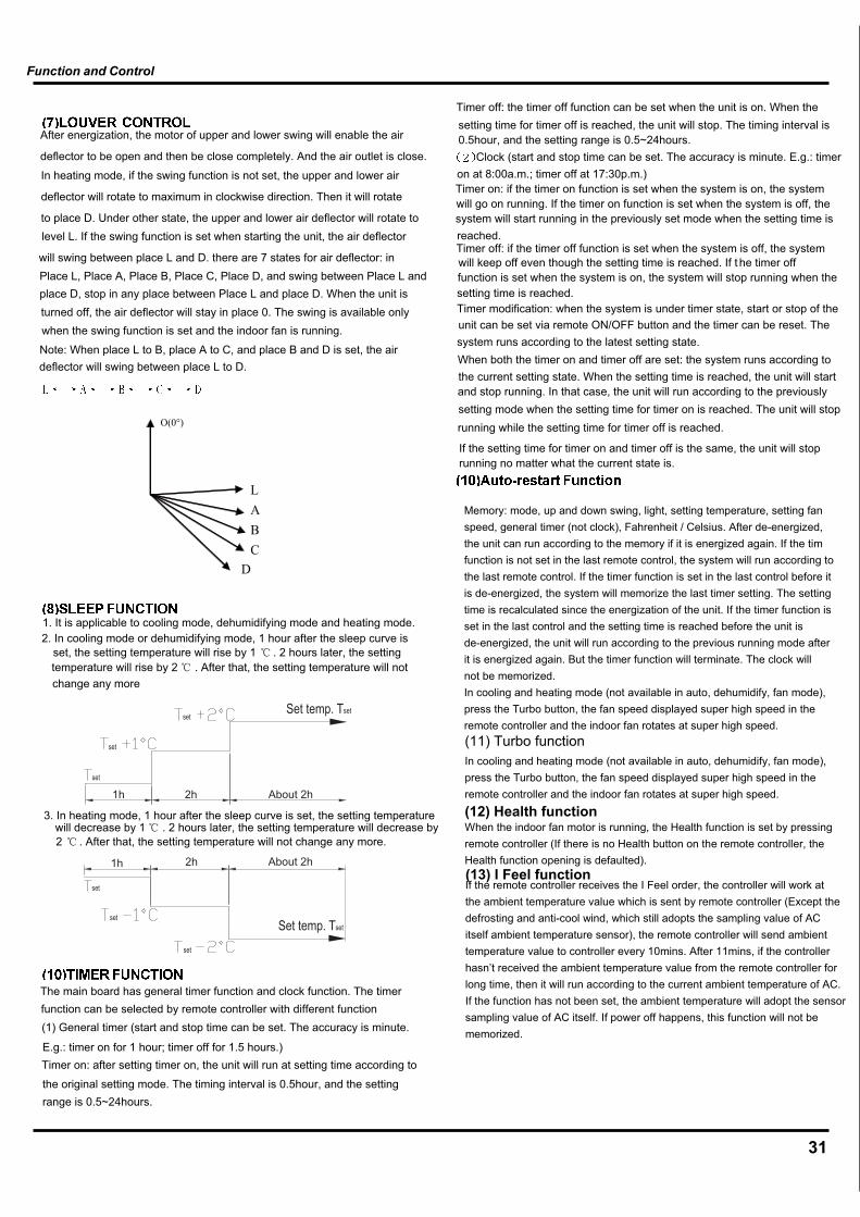
After energization, the motor of upper and lower swing will enable the air
deflector to be open and then be close completely. And the air outlet is close.
In heating mode, if the swing function is not set, the upper and lower air
deflector will rotate to maximum in clockwise direction. Then it will rotate
to place D. Under other state, the upper and lower air deflector will rotate tolevel L. If the swing function is set when starting the unit, the air deflector
will swing between place L and D. there are 7 states for air deflector: in Place L, Place A, Place B, Place C, Place D, and swing between Place L andplace D, stop in any place between Place L and place D. When the unit isturned off, the air deflector will stay in place 0. The swing is available onlywhen the swing function is set and the indoor fan is running.
Note: When place L to B, place A to C, and place B and D is set, the air deflector will swing between place L to D.
1. It is applicable to cooling mode, dehumidifying mode and heating mode.2. In cooling mode or dehumidifying mode, 1 hour after the sleep curve is
set, the setting temperature will rise by 1 . 2 hours later, the settingtemperature will rise by 2 . After that, the setting temperature will notchange any more
3. In heating mode, 1 hour after the sleep curve is set, the setting temperaturewill decrease by 1 . 2 hours later, the setting temperature will decrease by2 . After that, the setting temperature will not change any more.
The main board has general timer function and clock function. The timer function can be selected by remote controller with different function(1) General timer (start and stop time can be set. The accuracy is minute.
E.g.: timer on for 1 hour; timer off for 1.5 hours.)Timer on: after setting timer on, the unit will run at setting time according to
the original setting mode. The timing interval is 0.5hour, and the settingrange is 0.5~24hours.
Timer off: the timer off function can be set when the unit is on. When thesetting time for timer off is reached, the unit will stop. The timing interval is0.5hour, and the setting range is 0.5~24hours.
Clock (start and stop time can be set. The accuracy is minute. E.g.: timeron at 8:00a.m.; timer off at 17:30p.m.)Timer on: if the timer on function is set when the system is on, the systemwill go on running. If the timer on function is set when the system is off, the system will start running in the previously set mode when the setting time isreached.Timer off: if the timer off function is set when the system is off, the systemwill keep off even though the setting time is reached. If t he timer offfunction is set when the system is on, the system will stop running when thesetting time is reached.Timer modification: when the system is under timer state, start or stop of theunit can be set via remote ON/OFF button and the timer can be reset. Thesystem runs according to the latest setting state.When both the timer on and timer off are set: the system runs according to the current setting state. When the setting time is reached, the unit will startand stop running. In that case, the unit will run according to the previouslysetting mode when the setting time for timer on is reached. The unit will stoprunning while the setting time for timer off is reached.
If the setting time for timer on and timer off is the same, the unit will stop running no matter what the current state is.
If the remote controller receives the I Feel order, the controller will work at the ambient temperature value which is sent by remote controller (Except the defrosting and anti-cool wind, which still adopts the sampling value of AC itself ambient temperature sensor), the remote controller will send ambient temperature value to controller every 10mins. After 11mins, if the controller hasn’t received the ambient temperature value from the remote controller for long time, then it will run according to the current ambient temperature of AC. If the function has not been set, the ambient temperature will adopt the sensor sampling value of AC itself. If power off happens, this function will not be memorized.
(11) Turbo function In cooling and heating mode (not available in auto, dehumidify, fan mode), press the Turbo button, the fan speed displayed super high speed in the remote controller and the indoor fan rotates at super high speed.
(12) Health function When the indoor fan motor is running, the Health function is set by pressing remote controller (If there is no Health button on the remote controller, the Health function opening is defaulted). (13) I Feel function
Memory: mode, up and down swing, light, setting temperature, setting fan speed, general timer (not clock), Fahrenheit / Celsius. After de-energized, the unit can run according to the memory if it is energized again. If the timfunction is not set in the last remote control, the system will run according to the last remote control. If the timer function is set in the last control before it is de-energized, the system will memorize the last timer setting. The setting time is recalculated since the energization of the unit. If the timer function isset in the last control and the setting time is reached before the unit is de-energized, the unit will run according to the previous running mode after it is energized again. But the timer function will terminate. The clock will not be memorized. In cooling and heating mode (not available in auto, dehumidify, fan mode), press the Turbo button, the fan speed displayed super high speed in the remote controller and the indoor fan rotates at super high speed.
31

32
Frequency Control
<Outline>When starting the compressor, or when conditions are varied due to the change of the room, the frequency must be initialized accordingto the D value of the indoor unit and the Q value of the indoor unit.Q value: Indoor unit output determined from indoor unit volume, air flow rate and other factors.
1. P controlCalculate D value in each sampling time (20 seconds), and adjust the frequency according to its difference from the frequencypreviously calculated.2. I controlIf the operating frequency is not change more than a certain fixed time, adjust the frequency up and down according to the D value,obtaining the fixed D value.When the D value is small...lower the frequency.When the D value is large...increase the frequency.3. Frequency management when other controls are functioningWhen frequency is drooping;Frequency management is carried out only when the frequency droops.For limiting lower limitFrequency management is carried out only when the frequency rises.4. Upper and lower limit of frequency by PI controlThe frequency upper and lower limits are set depending on indoor unit.When low noise commands come from the indoor unit or when outdoor unit low noise or quiet commands come from indoor unit, theupper limit frequency must be lowered than the usual setting.
3-minutes StandbyProhibit to turn ON the compressor for 3 minutes after turning it off.(except when defrosting)
Compressor Protection FunctionWhen turning the compressor from OFF to ON, the upper limit of frequency must be set as follows. (The function must not be used whendefrosting.)
FCG 3
FCG 2
FCG 1
TCG1
TCG2
TCG3
88
64
48
240
360
180TCG 1sec TCG 2sec TCG 3sec Time
Frequency
FCG3FCG2FCG1
Function and Control
(1) Indoor temperature sensorDetect malfunctions of temperature sensor any time.
(2) Indoor pipe temperature sensor In defrosting period, the temperature sensor malfunction will not be detected. 5 min after finishing defrosting, the system begins to detect the temperature sensor malfunction. In other times, the temperature sensor malfunction will be detected.
(3) Protection of temperature sensor1. When short-circuit occurs to the temperature sensor for 30s:The temperature sensor overheats. In this case, the complete unit will stop for protection. At the same time, the temperature protection and temperature sensor malfunction will be shown.2. When break-circuit occurs to the temperature sensor for 30s:The unit will stop and the temperature sensor malfunction will be displayed
Temperature sensor malfunction detection
33
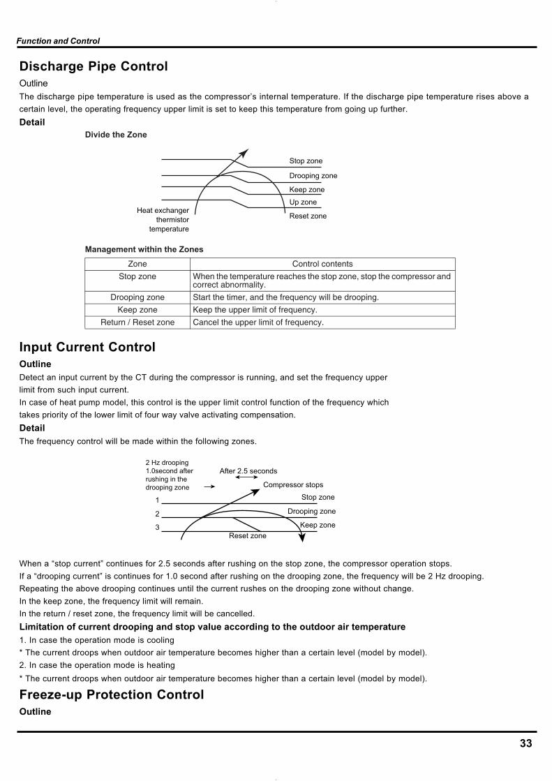
Discharge Pipe ControlOutlineThe discharge pipe temperature is used as the compressor’s internal temperature. If the discharge pipe temperature rises above acertain level, the operating frequency upper limit is set to keep this temperature from going up further.Detail
Input Current ControlOutlineDetect an input current by the CT during the compressor is running, and set the frequency upperlimit from such input current.In case of heat pump model, this control is the upper limit control function of the frequency whichtakes priority of the lower limit of four way valve activating compensation.DetailThe frequency control will be made within the following zones.
When a “stop current” continues for 2.5 seconds after rushing on the stop zone, the compressor operation stops.If a “drooping current” is continues for 1.0 second after rushing on the drooping zone, the frequency will be 2 Hz drooping.Repeating the above drooping continues until the current rushes on the drooping zone without change.In the keep zone, the frequency limit will remain.In the return / reset zone, the frequency limit will be cancelled.Limitation of current drooping and stop value according to the outdoor air temperature1. In case the operation mode is cooling* The current droops when outdoor air temperature becomes higher than a certain level (model by model).2. In case the operation mode is heating* The current droops when outdoor air temperature becomes higher than a certain level (model by model).
Freeze-up Protection ControlOutline
Divide the Zone
Management within the Zones
stnetnoclortnoCenoZ
Stop zone When the temperature reaches the stop zone, stop the compressor and correct abnormality.
Drooping zone Start the timer, and the frequency will be drooping.
Keep zone Keep the upper limit of frequency.
Return / Reset zone Cancel the upper limit of frequency.
Heat exchangerthermistor
temperature
Stop zone
Drooping zone
Keep zone
Up zone
Reset zone
2 Hz drooping1.0second afterrushing in thedrooping zone
After 2.5 seconds
Compressor stops
Stop zone
Drooping zone
Keep zoneReset zone
1
2
3
Function and Control

34
During cooling operation, the signals being sent from the indoor unit allow the operating frequency limitation and then prevent freezingof the indoor heat exchanger. (The signal from the indoor unit must be divided into the zones as the followings.)DetailConditions for Start ControllingJudge the controlling start with the indoor heat exchanger temperature after 2 sec from operation start.Control in Each Zone
Heating Peak-cut ControlOutlineHeat Pump OnlyDuring heating operation, the signals being sent from the indoor unit allow the operating frequency limitation and prevent abnormalhigh pressure. (The signal from the indoor unit must be divided as follows.)DetailConditions for Start ControllingJudge the controlling start with the indoor heat exchanger temperature after 2 sec. from operation start.Control in Each ZoneThe heat exchange intermediate temperature of indoor unit controls the following.
Defrost ControlOutlineHeat Pump OnlyDefrosting is carried out by the cooling cycle (reverse cycle). The defrosting time or outdoor heat exchanger temperature must be morethan its fixed value when finishing.DetailConditions for Starting DefrostThe starting conditions must be made with the outdoor air temperature and heat exchanger temperature. Under the conditions that thesystem is in heating operation, 6 minutes after the compressor is started and more than 44 minutes of accumulated time pass sincethe start of the operation or ending the defrosting.Conditions for Canceling DefrostThe judgment must be made with heat exchanger temperature. (39°F~72°F)
AB
C
D
E
Return/Reset zone
Up zone
Keep zoneDrooping zone
Stop zone
Heat exchangerthermistor temperature
Reset zone
Up zoneKeep zoneDrooping zone
Stop zone
Heat exchangerthermistor temperature
Function and Control
35
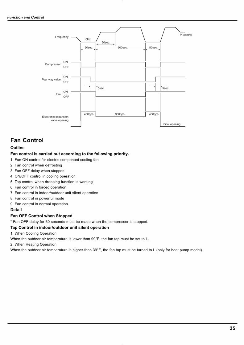
Fan ControlOutlineFan control is carried out according to the following priority.1. Fan ON control for electric component cooling fan2. Fan control when defrosting3. Fan OFF delay when stopped4. ON/OFF control in cooling operation5. Tap control when drooping function is working6. Fan control in forced operation7. Fan control in indoor/outdoor unit silent operation8. Fan control in powerful mode9. Fan control in normal operationDetailFan OFF Control when Stopped* Fan OFF delay for 60 seconds must be made when the compressor is stopped.Tap Control in indoor/outdoor unit silent operation1. When Cooling OperationWhen the outdoor air temperature is lower than 99°F, the fan tap must be set to L.2. When Heating OperationWhen the outdoor air temperature is higher than 39°F, the fan tap must be turned to L (only for heat pump model).
Frequency
Compressor
Four way valve
Fan
Electronic expansionvalve opening
ON
OFF
ON
OFF
ON
OFF
0Hz
5sec.
350pps 450pps450pps
Initial opening
PI control
5sec.
50sec.50sec. 600sec.
60sec.
Function and Control

36
7. Installation Manual Important Notices
1. The unit installation work must be done by qualifiedpersonnel according to the local rules and thismanual.2. Before installating, please contact with localauthorized maintenance center, if unit is not installedby the authorized maintenance center, the malfunctionmay not solved, due to discommodious contacts.3. When removing the unit to the o.ther place, pleasefirstly contact with the authorized MaintenanceCenter in the local area.
Basic Requirements For InstallationPositionInstall in the following place may cause malfunction. If it isunavoidable contact with service center please:* Place where strong heat sources, vapors, flammable gas orvolatile object are emitted.* Place where high-frequency waves are generated by radioequipment, welders and medical equipment.* Place where a lot of salinities such as coast exists.* Place where the oil (machine oil) is contained in the air.* Place where a sulfured gas such as the hot spring zones isgenerated.* Other place with special circumstance.
7.1 Tools Required for Installation(not supplied)1. Gauge manifold2.Electronic balance for refrigerant charging3. Phillips head screwdriver4. Knife or wire stripper5. Carpenter’s level9. Hammer10. Drill11. Tube cutter12. Tube flaring tool13. Torque wrench14. Adjustable wrench15. Reamer (for deburring)16. Vacuum pump (For R410A)17. Gas leakage detector
7.2 Installation Position Selection
(1)The air inlet and outlet vent should be far from the obstruction,make sure that the air can be blown through the whole room.(2)Select a position where the condensing water can be easilydrained out, and the place is easily connected for outdoor unit.(3)Select a location where the children can not reach.(4)Can select the place where is strong enough to withstand thefull weight and vibration of the unit. And will not increase the noise.(5)Be sure to leave enough space to allow access for routinemaintenance. The height of the installed location should be250cm or more from the floor.(6)Select a place about 1m or more away from TVset or any otherelectric appliances.(7)Select a place where the filter can be easily taken out.(8)Make sure that the indoor unit installation should accord withinstallation dimension diagram requirements.(9)Do not use the unit in the immediate surroundings of a laun-dry a bath a shower or a swimming pool.
(1)Select a location from which noise and outflow air emitted byunit will not inconvenience neighbors, animals, plants.(2)Select a location where there should be sufficient ventilation.(3)Select a location where there should be no obstructions coverthe inlet and outlet vent.(4)The location should be able to withstand the full weight andvibration of the outdoor unit and permit safe installation.(5)Select a dry place, but do not expose under the direct sunlightor strong wind.(6)Make sure that the outdoor unit installation dimension shouldaccord with installation dimension diagram, convenient formaintenance, repair.(7)The height difference of connecting the tubing within 5m, thelength of connecting the tubing within 10m.(8)Select a place where it is out of reach for the children.(9)Select a place where will not block the passage and do notinfluence the city appearance.
7.3 Installation of Indoor Unit
The mounting plate should be installed on a wall which can sup-port the weight of the indoor unit.1) Temporarily secure the mounting plate to the wall, make surethat the panel is completely level, and mark the boring points onthe wall.2) Secure the mounting plate to the wall with screws.
Installation Manual
37
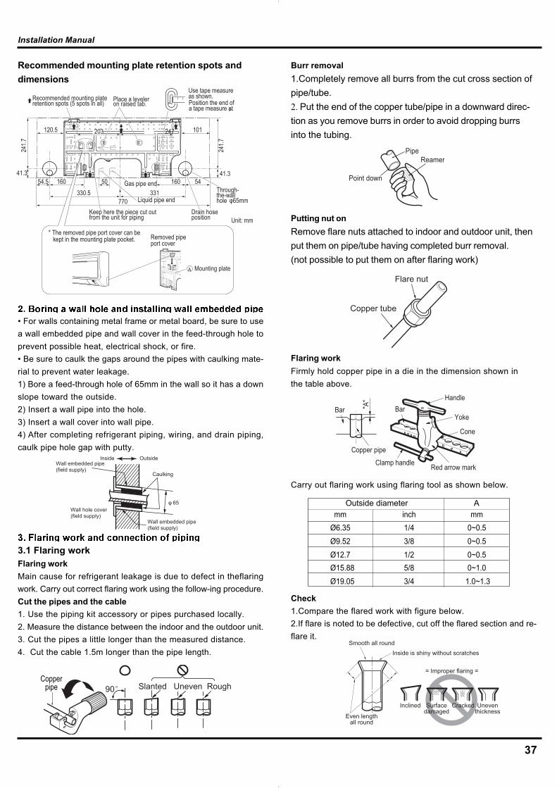
Burr removal1.Completely remove all burrs from the cut cross section ofpipe/tube.2. Put the end of the copper tube/pipe in a downward direc-tion as you remove burrs in order to avoid dropping burrsinto the tubing.
Putting nut onRemove flare nuts attached to indoor and outdoor unit, thenput them on pipe/tube having completed burr removal.(not possible to put them on after flaring work)
Flaring workFirmly hold copper pipe in a die in the dimension shown inthe table above.
Carry out flaring work using flaring tool as shown below.
Check1.Compare the flared work with figure below.2.If flare is noted to be defective, cut off the flared section and re-flare it.
• For walls containing metal frame or metal board, be sure to usea wall embedded pipe and wall cover in the feed-through hole toprevent possible heat, electrical shock, or fire.• Be sure to caulk the gaps around the pipes with caulking mate-rial to prevent water leakage.1) Bore a feed-through hole of 65mm in the wall so it has a downslope toward the outside.2) Insert a wall pipe into the hole.3) Insert a wall cover into wall pipe.4) After completing refrigerant piping, wiring, and drain piping,caulk pipe hole gap with putty.
3.1 Flaring workFlaring workMain cause for refrigerant leakage is due to defect in theflaringwork. Carry out correct flaring work using the follow-ing procedure.Cut the pipes and the cable1. Use the piping kit accessory or pipes purchased locally.2. Measure the distance between the indoor and the outdoor unit.3. Cut the pipes a little longer than the measured distance.4. Cut the cable 1.5m longer than the pipe length.
Recommended mounting plate retention spots anddimensions
770
Use tape measure as shown.Position the end of a tape measure at .
Keep here the piece cut out from the unit for piping Unit: mm
Gas pipe endThrough-the-wall hole φ65mm
Recommended mounting plate retention spots (5 spots in all) Place a leveler
on raised tab.
41.341.3
241.7
54330.5
241.7
16054.5 50160
101120.5
331
203 247
Drain hose position
Liquid pipe end
* The removed pipe port cover can be kept in the mounting plate pocket. Removed pipe
port cover
A Mounting plate
Copperpipe 90 Slanted Uneven Rough
PipeReamer
Point down
Flare nut
Copper tube
Bar
Copper pipe
Clamp handle Red arrow mark
Cone
Yoke
HandleBar"A
"
mm inch mmØ6.35 1/4 0~0.5Ø9.52 3/8 0~0.5Ø12.7 1/2 0~0.5Ø15.88 5/8 0~1.0Ø19.05 3/4 1.0~1.3
Outside diameter A
Inclined
Inside is shiny without scratchesSmooth all round
Even lengthall round
Surfacedamaged
Cracked Uneventhickness
= Improper flaring =
Installation Manual
Inside Outside
Caulking
Wall embedded pipe (field supply)
Wall hole cover(field supply)
Wall embedded pipe (field supply)
φ 65

38
3.2 Connection of piping1.Align the center of the pipes and sufficiently tighten the flare nutby hand.
2.Tighten the flare nut with a wrench.
If drain hose extension or embedded drain piping is required,use appropriate parts that match the hose front end.Insert drain hose into the handle of drain pan, and joindrain hose and connecting hose according to the figure by.
Wiring the connecting cable can be carried out without remov-ing the front panel.1. Remove the air inlet grille. Open the air inlet grille upward andpull it toward you.2. Remove the terminal cover and cord clamp.3. Insert the connecting cable (or as according to local regula-tions/codes) into the pipe hole on the wall.4. Pull the connecting cable through the cable slot on the rearpanel so that it protrudes about 15 cm out of the front.
Insulation (Drain hose)
Drain hose
CAUTION
Insert the drain hose and drain cap into the drain port, mak-ing sure that it comes in contact with the back of the drainport, and then mount it. If the drain hose is not connectedproperly, leaking will occur.
• Attach the Insulation (Drain hose) to the drain hose.
CAUTION
Indoor unit tubing Flare nut Pipes
Wrench
Indoor unit tubing
Open-end wrench (fixed)
Connection pipe
Flare nut
mm inch kg.mØ6.35 1/4 1.8Ø9.52 3/8 4.2Ø12.7 1/2 5.5Ø15.88 5/8 6.6Ø19.05 3/4 6.6
Outside diameter Torque
Shield pipe
Extension drain hoseInside the roomDrain hose
5. Insert the connecting cable fully into the terminal block andsecure it tightly with screws.6. Tightening torque: 1.2 N•m (0.12 kgf•m).7. Secure the connecting cable with the cord clamp.8. Attach the terminal cover, rear plate bushing and air inlet grilleon the indoor unit.
ScrewScrew
Terminal cover
Cord clamp
Terminal block
Earth wire
Connecting cable
Terminal block
Connecting cable
About 15 cm
Earth line
70 mm
10 mm
10 mm50 mm
• Be sure to refer to the wiring system diagramlabeled inside the front panel.• Check local electrical regulations for anyspecific wiring instructions or limitations.
CAUTION
Installation Manual

39
1.After making slits on the front panel with a knife or similar tool,cut them out with a pair of nippers or an equivalent tool.
2.Overlap the connection pipe insulation material and the indoorunit pipe insulation material. Bind them together with vinyl tapeso that there is no gap.
3.Wrap the area which accommodates the rear piping housingsection with vinyl tape.
4.Bundle the piping and drain hose together by wrapping themwith vinyl tape for enough to cover where they fit into the rearpiping housing section.Indoor unit installation1) Pass the drain hose and refrigerant pipes through the wallhole, then set the indoor unit on the mounting plate hooks byusing the markings at the top of the indoor unit as a guide.
In the case of bending or curing refrigerant pipes, keep the fol-lowing precautions in mind.Abnormal sound may be generated if improper work is conducted.1) Do not strongly press the refrigerant pipes onto the bottomframe.2) Do not strongly press the refrigerant pipes on the front grille,either.
The piping can be lead out from right, right rear, left left rear.Right-side, right-back, or right-bottom piping1)After making slits on the front panel with a knife or similar tool,cut them out with a pair of nippers or an equivalent tool. Attach the drain hose to the underside of the refrigerant pipeswith an adhesive vinyl tape.2) Wrap the refrigerant pipes and drain hose together with aninsulation tape.
Left-side, left-back, or left-bottom piping• Interchange the drain cap and the drain hose.
1)
2)
Right pipingBind with vinyl tape
Indoor unit drain hose(bottom)
Pipe (top)Rear piping
Bottompiping
Drain capIndoor unitdrain hose
Remove the drain cap by pullingat the projection at the end ofthe cap with pliers, etc.
For left outlet piping, cut off thepiping outlet cutting groovewith a hacksaw.
CAUTION(1) In order to align the drain hose and drain cap, be
sure to insert securely and vertically. Incline inser-tion will cause water leakage.
(2) When inserting, be sure not to attach any materialbesides water. If any other material is attached, itwill cause deterioration and water leakage.
(3) After removing drain hose, be sure not to forgetmounting drain cap.
(4) Be sure to fix the drain hose with tape to the bottomof piping.
(5) Prevent drain water frozen under low tempera-ture environment.When installing indoor unit's drain hose outdoors, necessarymeasure for frost protection should be taken to prevent drainwater frozen.• Under low temperature environment (when outdoor tem-
perature under 32 °F), after cooling operation is executed,water in the drain hose could be frozen.Once drain water is frozen, the drain hose will be blockedand water leakage may be resulted for indoor unit.
Slit
Plastic bands Insulation material
Connectionpipe
Vinyl tape(wide)
Wrap with vinyl tape
Indoorunit pipe
Wrap with vinyl tape
Drain hose
Pipe
Vinyl tape(wide)
Installationplate
Indoor unit
Connectingcable
Auxiliary pipes
Installation Manual
How to replace the drain plug and drain hose• How to remove the drain capClamp drain cap with needle-nose pliers, and pull out.
• How to remove the drain hoseThe drain hose is secured in place by a screw.Remove the screw securing the drain hose, thenpull out the drain hose.
• How to attach the drain cap1. Insert hexagonal wrench (4 mm).
2. Firmly insert drain cap.
• How to attach the drain hoseInsert the drain hose firmly until the connector contacts the insulation, thensecure it in place using the original screw.
esohniarD
Insulationfixing screw
Do not apply lubricating oil (refrigerant machine oil) when inserting the drain cap. If applied, deterioration and leakage of the drain plug may occur.
Insert a hexagon wrench (4 mm)
No gap

40
Remove the Valve cover from the unit by loosening the screw.Align the center of the pipings and sufficiently tighten the flarenut by hand.
Finally, tighten the flare nut with torque wrench until the wrenchclicks.
2.Overlap the connection pipe insulation material and the indoorunit pipe insulation material. Bind them together with vinyl tapeso that there is no gap.
After the piping has been connected to the indoor unit, performthe air purge.
Air purging with vacuum pumpBe sure to use a vacuum pump with counter-flow preventionfunction so that oil inside the pump does not flow back into theair conditioner pipes when the pump stops. (If oil inside thevacuum pump enters into the air conditioner circuit which usesR410A, trouble with the refrigeration system may develop.)
2) Swing the indoor unit to right and left to confirm that it is firmlyhooked on the installation plate.3)While pressing the indoor unit onto the wall, hook it at the lowerpart on the installation plate.Pull the indoor unit toward you to confirm that it is firmlyhooked on the installation plate.For detaching the indoor unit from the installation plate pull theindoor unit toward you while pushing the bottom up at thespecified places.
4)Run the drain hose at a downward sloped angle.
5)Put water in the drain pan and make sure that the water isbeing drained outside.Caution:Install the drain pipe for proper drainage. Improper drainage canresult in water dripping inside the room.
7.4 Installation of Outdoor Unit
* Holes are provided on the base plate of the outdoor unit toensure that the defrost water produced during heating opera-tions is drained off efficiently.* If a centralized drain is required when installing the unit on abalcony or wall.* If the drain port is covered by a mounting base or floor surface,place additional foot bases of at least 30mm in height under theoutdoor unit’s feet.* In cold areas, do not use a drain hose with the outdoor unit.(Otherwise, drain water may freeze, impair ing heatingperformance.)
Push Push
50 mmor more
Do not rise the drain hose. Do not form the drain hose into the waved shape.
Do not put the drain hose end into water.
Do not put the drain hose end in the drainage ditch.
Drain-water hole
Bottom frame
Drain plug
Hose (available commercially,inner dia. 16mm)
Liquid side piping
Outdoor unit
Gas side piping(Bigger diameter)
(Smaller diameter)
Torque wrench
AIR PURGEEvacuate the air in the connecting pipes and in the indoorunit using a vacuum pump.Do not use the refrigerant in the outdoor unit.For details, see the vacuum pump manual.
Installation Manual
Mounting plateA
Marking

41
1. Connect the charge hose from the manifold valve to the serviceport of the gas side packed valve.2. Connect the charge hose to the port of the vacuum pump.3. Open fully the low pressure side handle of the gauge manifoldvalve.4. Operate the vacuum pump to begin evacuating. Perform evacu-ating for about 15 minutes if the piping length is 20 meters (15minutes for 20 meters) (assuming a pump capacity of 27 litersper minute). Confirm that the compound pressure gauge read-ing is –101 kPa (–76 cmHg).5. Close the low pressure valve handle of gauge manifold.6. Open fully the valve stem of the packed valves (both sides ofGas and Liquid).7. Remove the charging hose from the service port.8. Securely tighten the caps on the packed valves.
CAUTION• IMPORTANT POINTS FOR PIPING WORK1. Keep dust and moisture from entering the pipes.2. Tighten connections carefully (between pipes and unit).3. Evacuate the air in the connecting pipes using a VACUUMPUMP.4. Check for gas leaks at all connections.Packed Valve handling precautions• Open the valve stem all the way; but do not try to open it beyondthe stopper.• Securely tighten the valve stem cap with torque in the followingtable:
Hexagon wrench(4mm)Cap
Compoundpressuregauge
Pressure gauge
Manifold valveHandle Hi(Keep full closed)
Charge hose(For R410A only)
Vacuum pump adapter for counter-flowprevention(For R410A only)
Packed valve at liquid side
Packed valve at gas side
Service port (Valve core (Setting pin))
Connectingpipe
Handle Lo
Charge hose(For R410A only)
-101kPa(-76cmHg)
Vacuum pump
1) Strip the insulation from the wire (20mm).2) Connect the connection wires between the indoor and outdoorunits so that the terminal numbers match. Tighten the terminalscrews securely.The screws are packed with the terminal board.
7.5 Test Operation1. Check that all tubing and wiring have been properly connected.2. Check that the gas and liquid side service valves are fullyopen.
Check the flare nut connections for gas leaks with a gas leakdetector and/or soapy water.
1)Switch on power, press “ON/OFF” button on the wireless re-mote control to start the operation.2)Press MODE button, to select the COOL, HEAT (Cooling onlyunit is not available), FAN to check whether the operation is nor-mal or not.Perform test operation and check items 1 and 2 below.1. INDOOR UNIT(1) Is operation of each button on the remote control unit normal?(2) Does each lamp light normally?(3) Do the air flow-direction louver operate normally?(4) Is the drain normal?2. OUTDOOR UNIT(1) Is there any abnormal noise and vibration during operation?(2) Will noise, wind, or drain water from the unit disturb theneighbors?(3) Is there any gas leakage?
Gas side (Ø9.52 mm)
Liquid side (Ø6.35 mm)
Service port
33 to 42 N•m (3.3 to 4.2 kgf •m)
14 to 18 N•m (1.4 to 1.8 kgf •m)
14 to 18 N•m (1.4 to 1.8 kgf •m)
Check places for flare nut connections(indoor unit)
Valve cover
Check places for outdoor unit
Electric parts
Installation Manual
Terminal block
power wire
wire clamp
power connect wire
wire clamp
42
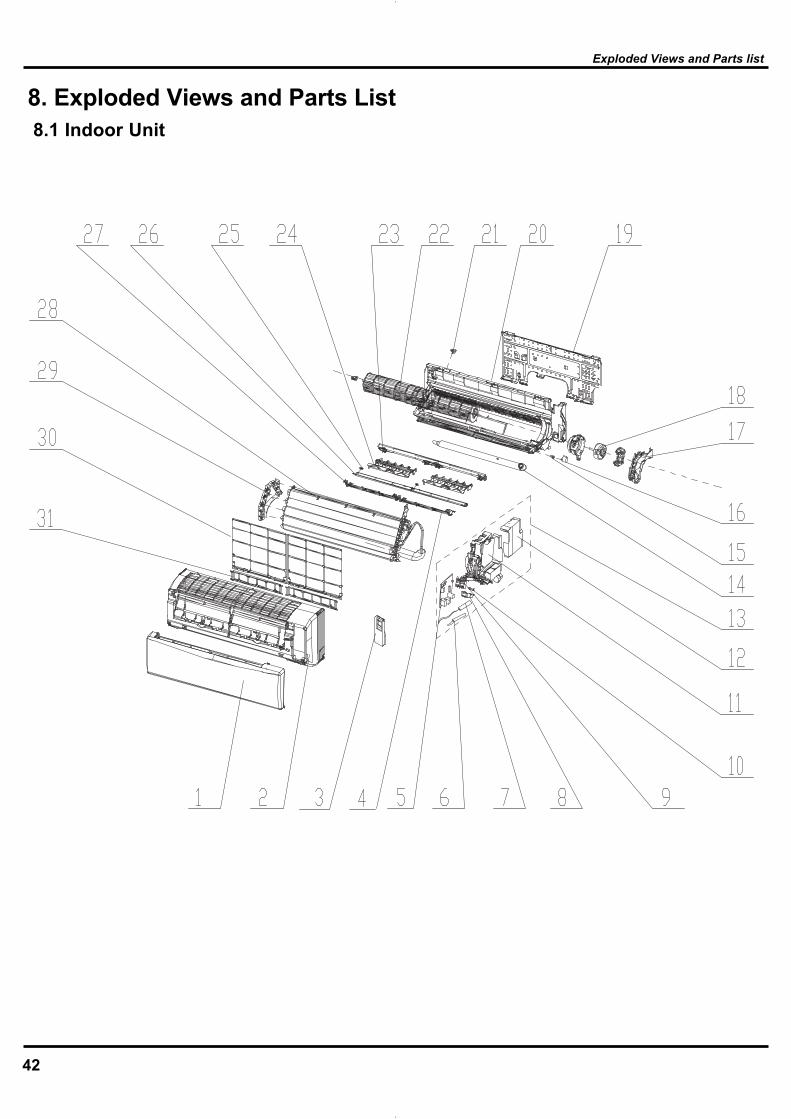
8. Exploded Views and Parts List 8.1 Indoor Unit
Exploded Views and Parts list

45
Exploded Views and Parts list

48
WST12MC16S WST12MH16S
Product Code CB146N0540 CB146N0550 1 Front panel 2 2001251001 2001251001 12 Front Case 2001237501 2001237501 13 Remote Controller 30510062 30510062 14 Rear grill sub-assy 2 11002001 11002001 15 Main Board 30138131 30138129 16 Ambient Temperature Sensor 390000453 39000305 17 Temperature Sensor 39000305 390000453 18 Indicator Light Cover 22242084 22242084 19 Terminal Board 42011233 42011233 110 Indicator shield cover 22242083 22242083 111 Electric Box Sub-Assy 2020227702 2020221703 112 Electric Box Cover Sub-Assy 20122109 20122109 113 Electric Box Assy 2020227602 2020217403 114 Drainage Pipe Sub-assy 0523204101 0523204101 115 Crank 73012005 73012005 116 Step Motor 1521210701 1521210701 117 Motor Press Plate 26112191 26112191 118 Fan Motor 1501209301 1501209301 119 Wall Mounting Frame 0125201801 0125201801 120 Rear Case assy 2220211902 2220211902 121 Pipe plug (outlet) 76712020 76712020 122 Cross Flow Fan 10352423 10352423 123 Helicoid tongue 26112486 26112486 124 Air Louver 10512160 10512160 225 Shaft of guide louver 1054202001 1054202001 226 Guide Louver 10512119 10512119 127 Rear grill sub-assy 24212911 24212911 128 Evaporator Assy 01002745 01002745 129 Evaporator Support 24212108 24212108 130 Filter Sub-Assy 1112208201 1112208201 231 Support of catechin 24212910 24212910 2
NODescription
PartCodeQty
The above data are subject to be changed without notice.
Exploded Views and Parts list
49
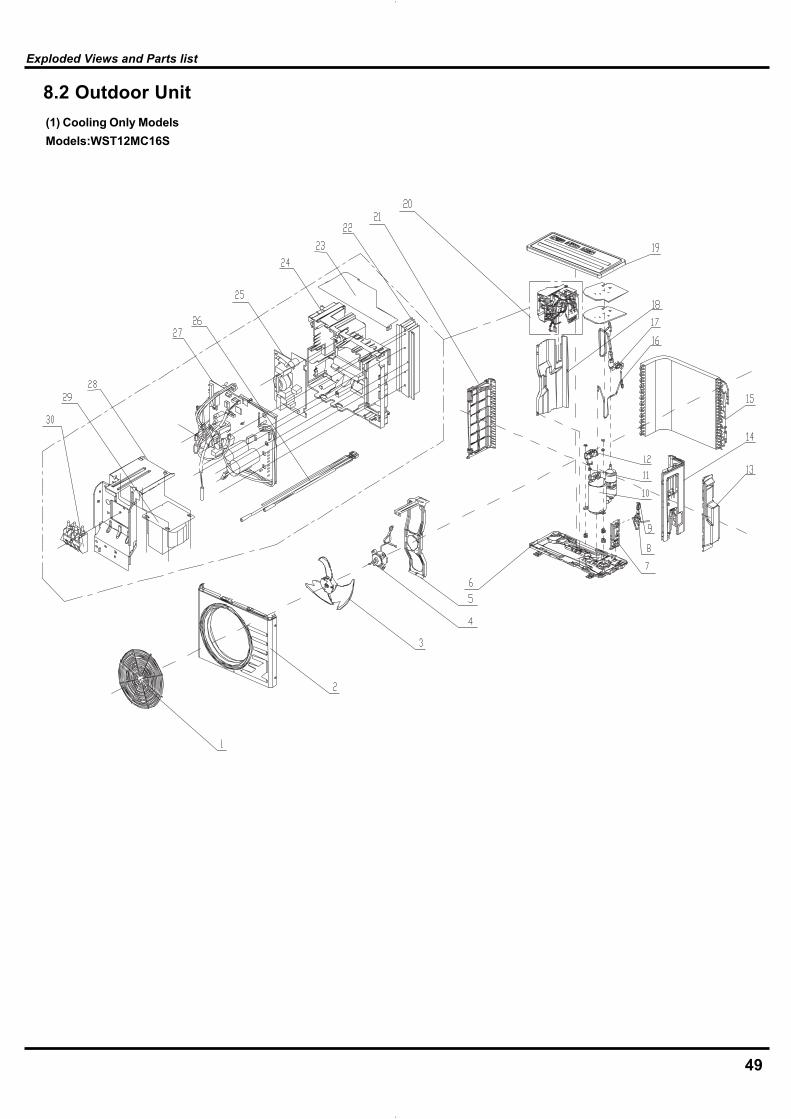
(1) Cooling Only Models Models:WST12MC16S
Exploded Views and Parts list
8.2 Outdoor Unit
53
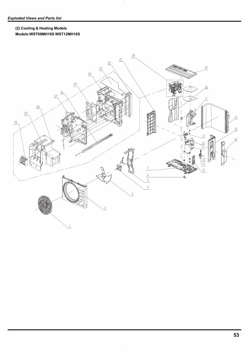
(2) Cooling & Heating Models Models:WST09MH16S WST12MH16S
Exploded Views and Parts list

57
9. Troubleshooting9.1 Precautions before Performing Inspection or Repair
Take sufficient care to avoid directly touching any of the circuit parts without first turning off the power.At times such as when the circuit board is to be replaced, place the circuit board assembly in a vertical position.Normally,diagnose troubles according to the trouble diagnosis procedure as described below.(Refer to the check points in servicingwritten on the wiring diagrams attached to the indoor/outdoor units.)
Precautions when inspecting the control section of the outdoorunit:A large-capacity electrolytic capacitor is used in the outdoor unit controller(inverter).Therefore,if the power supply is turned off,charge(charging volt-age DC280V to 380V)remains and discharging takes a lot of time.. Afterturning off the power source,if touching the charging section beforedischarging, an electrical shock may be caused.
9.2 Confirmation(1)Confirmation of Power SupplyConfirm that the power breaker operates(ON) normally;(2)Confirmation of Power VoltageConfirm that power voltage is AC 208~230 ± 10%.If power voltage is not in this range, the unit may not operate normally.
9.3 Judgement by Flashing LED of Indoor/Outdoor Unit
Troubleshooting
No. Troubleshooting procedure
1 Confirmation
2 Judgement by Flashing LED of Indoor/Outdoor Unit
3 How to Check simply the main part
Be cautious during installation and maintenance. Do operation following the regulations to avoid electric shock and casualty or even death due to drop
from high attitude.* Static maintenance is the maintenance during de-energization of the air conditioner.For static maintenance, make sure that the unit is de-energized and the plug is disconnected.
*dynamic maintenance is the maintenance during energization of the unit.Before dynamic maintenance, check the electricity and ensure that there is ground wire on the site. Check if there is electricity on the housing and connection copper pipe of the air conditioner with voltage tester. After ensure insulation place and the safety, the maintenance can be performed.
The outdoor unit can not be started up until the unit is de-energized for 20min

58
Troubleshooting
Error display Error display code malfunction
Dual 8 display
LED
Repair method code malfunction
Dual 8 display
LED
Repair method
1 Storage slug EE HeatingLED-pause 3s and blink 15 times
Replace indoor main board
15 Sync failure H7 Heating LED-pause 3s and blink 7 times
Check if the resistance of compressor and resistance to ground is normal. If the compressor is normal, the outdoor main boar d may be wrong.
2 Indoor PCB malfunction
EE HeatingLED-pause 3s and blink 15 times
Replace indoor main board
16 Current diction malfunction of complete unit
U5 CoolingLED-pause 3s and blink 13 times
Replace outdoor main board
3 Anti-freezing protection
E2 Running LED- pause 3s and blink 2 times
Outdoor ambient temperature is too low
17 Outdoor ambient temperature sensor malfunction
F3 CoolingLED-pause 3s and blink 3 times
Is it loose? Measure the resistance value with universal meter
4 Overload of system
H4 HeatingLED-pause 3s and blink 4 times
System is abnormal, check if the evaporator and condenser is dirty and blocked
18 Discharge protection of compressor
E4 RunningLED-pause 3s and blink 4 times
Is it loose? Measure the resistance value with universal meter
5 No motor of indoor unit feedback
H6 Running LED- pause 3s and blink 11 times
Is electromotor mounted normally?
19 Break-circuit and short-circuit of outdoor discharge temperature sensor
F5 cooling LED- pause 3s and blink 5 times
Is it loose? Measure the resistance value with universal meter
6 Indoor pipe temperature sensor malfunction
F2 cooling LED- pause 3s and blink 2 times
Is it loose? Measure the resistance value with universal meter
20 Break-circuit and short-circuit of outdoor condenser temperature sensor
F4 cooling LED- pause 3s and blink 18 times
Is it loose? Measure the resistance value with universal meter
7 Internal ambient temperature sensor malfunction
F1 Cooling LED- pause 3s and blink 1 times
Is it loose? Measure the resistance value with universal meter
21 Overheat of carbon fin
P8 heating LED- pause 3s and blink 19 times
Is outdoor ambient temperature is too high? Is radiator mounted correctly?
8 Zero passage abnormal
UF Heating and cooling LED blinks 7 times at the same time
Replace indoor main board
22 DC overcurrent UU Heating and cooling LED blink 11 times at the same time
9 Overload of compressor
H3 heating LED- pause 3s and blink 3 times
Inspect connection state of the overload wire.
23 Temperature sensor malfunction of carbon fin
P7 heating LED- pause 3s and blink 18 times
Replace outdoor main board.
10 Startup failure Lc heating LED- pause 3s and blink 11 times
Check if the resistance of compressor and resistance to ground is normal. If the compressor is normal, the outdoor main boar d may be wrong.
24 Lack of Freon or block protection
F0 cooling LED-pause 3s and blink 10 times
11 No motor of outdoor unit feedback
UH Heating and cooling LED blink 8 times at the same time
This malfunction may happen when outdoor DCelectromotor is used.
25 DC input voltage is too high
PH cooling LED- pause 3s and blink 11 times
Is voltage of AC power supply normal?
12 Overcurrent protection
E5 Running LED- pause 3s and blink 5 times
Is electric network variable?
26 DC input voltage is too low
PL Heating LED- pause 3s and blink 21 times
Is voltage of AC power supply normal?
13 4-way valve conversion abnormal
U7 cooling LED- pause 3s and blink 20 times
Replace 4-way valve.
27 Communication malfunction
E6 Running LED- pause 3s and blink 6 times
Is outdoor connecting wire reliably connected?
14 Phase current detection malfunction of compressor
U1 Heating LED- pause 3s and blink 13 times
Replaceoutdoor main board.
28 Setting error, indoor and outdoor unit abnormal
UA Heating and cooling LED blink 12 times at the same time
Outdoor unit is not matched with indoor unit.
remarks
4min after protection stop of compressor, the malfunction is shown in error code. In other situation, the malfunction will be displayed by press the light button for 6 times within 4s.

Indoor fan does not rotate without feedback n detection point: Is the control panel reliably connected with the electromotor? Is it loose? Is the connecting sequence correct?
Is the input voltage within the normal range (measure the voltage between L and N of the wiring block XT with AC voltage gauge.)
Malfunction diagnosis process:
Mai
Y
Y
Y
N
N
N
Y
N
Energize the unit and start it
Voltage > 200V?
Voltage between L and N of indoor
wiring block
Check the connecting state of the
connecting terminal
Reliableconnection
Adjust
connecting state
Check power supplyReplace main
board of indoor unit
remove the error?
remove the error?
Replace motor
Finish
Temperature sensor malfunction
Main detection point:Is outdoor ambient temperature within the normal range?
Is indoor and outdoor fan running normally?
Is the radiating environment inside and outside the unit good enough?
Malfunction diagnosis process:
59
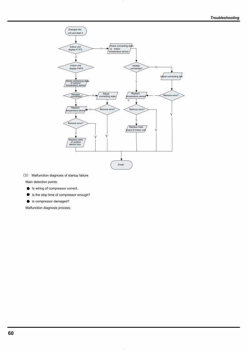
Troubleshooting
Y
Y
N
N
Y
N
N
Y
Y
N
N
N
YY
Y
Energize the unit and start it
Indoor unit display F1/F2
Check connecting state of indoor
temperature sensor
ndoor unitdisplay F4/F5I reliable
connected?
Check connecting stateof outdoor
temperature sensor
Adjust connecting stat
Reliableconnected?
Adjustconnecting state
Replacetemperature sensor Remove error?
Remove error? Remove error?
Remove error?
Replace temperature sensor?
Replace main board of indoor unit
Replace parts of outdoor
electric box
Finish
Malfunction diagnosis of startup failure
Main detection points:
Is wiring of compressor correct.
Is the stop time of compressor enough?
Is compressor damaged?
Malfunction diagnosis process:
60
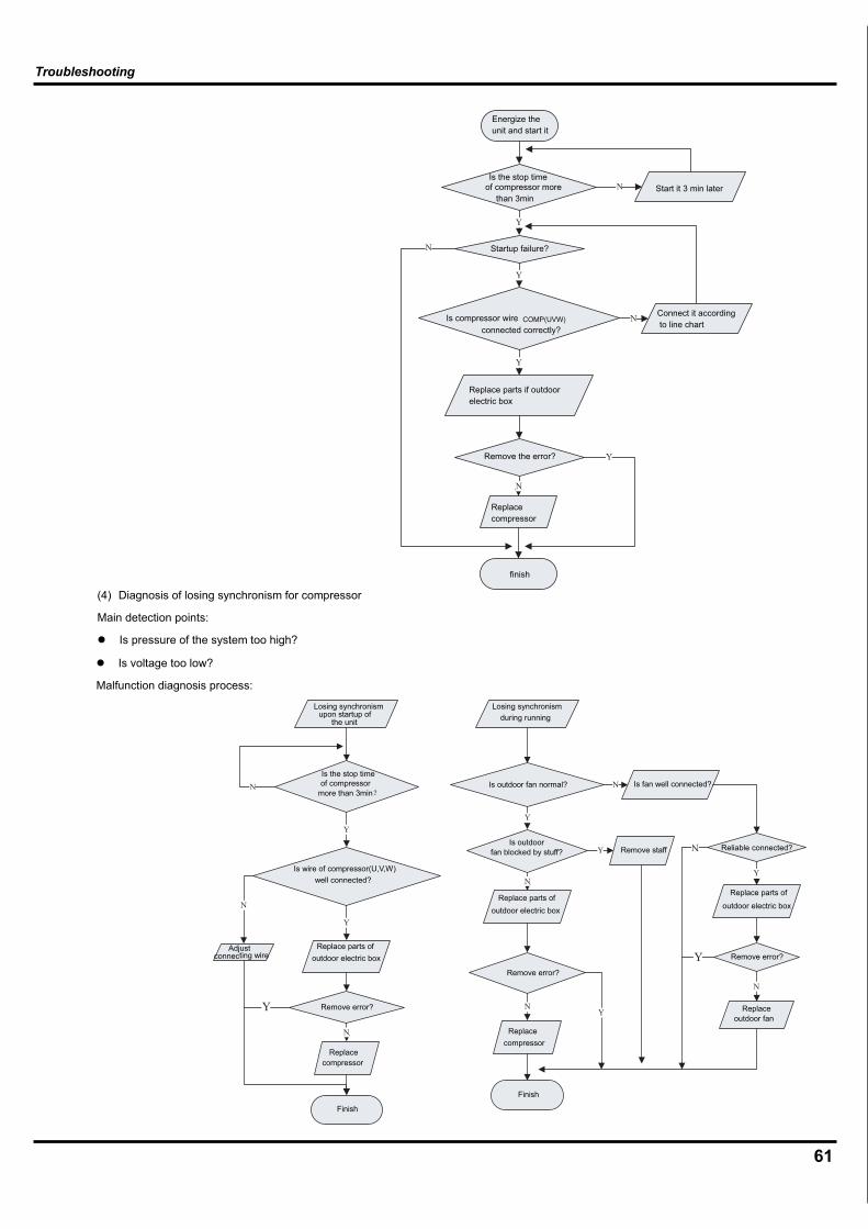
Troubleshooting
Y
N
N
N
Y
Y
Y
N
Y
N
N
Y
Y
N
N
Y
Y
N
Y
N
N
Y
Y
N
Energize the unit and start it
Is the stop timeof compressor more
than 3minStart it 3 min later
Startup failure?
Is compressor wire connected correctly?
Connect it according to line chart
Replace parts if outdoor electric box
Remove the error?
Replacecompressor
finish
(4) Diagnosis of losing synchronism for compressor
Main detection points:
Is pressure of the system too high?
Is voltage too low?
Malfunction diagnosis process:
COMP(UVW)
Finish
Finish
Losing synchronism upon startup of
the unit
Losing synchronism during running
Is the stop time of compressor
more than 3minIs outdoor fan normal? Is fan well connected?
Is wire of compressor(U,V,W) well connected?
Is outdoor fan blocked by stuff? Remove staff Reliable connected?
Replace parts of outdoor electric box
Replace parts of
outdoor electric box
Replace parts of outdoor electric box
Adjust connecting wire
Remove error?
Remove error?
Remove error?
Replacecompressor
Replacecompressor
Replace outdoor fan
61
Troubleshooting
N
N
N
Y
Y
Y
Y
N
Y
N
N
Y
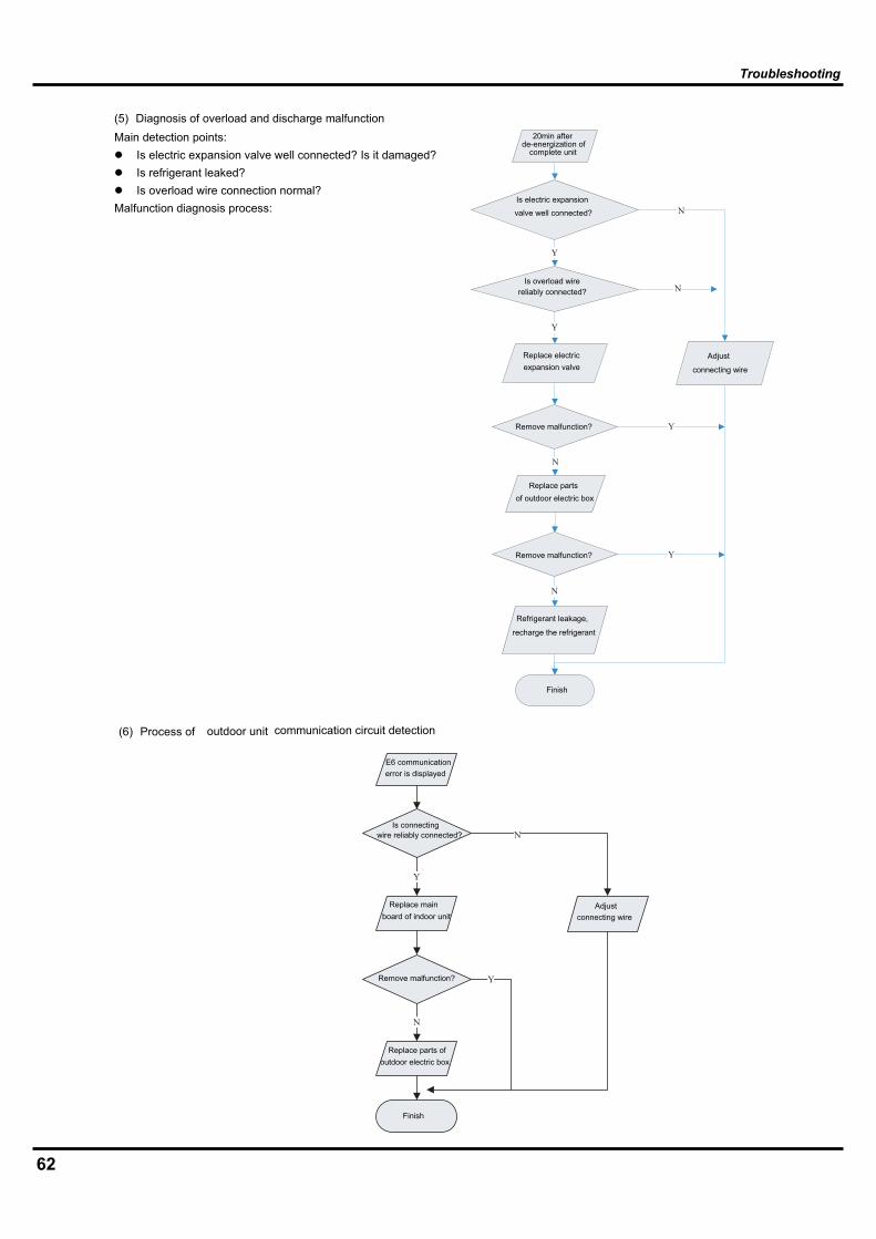
(5) Diagnosis of overload and discharge malfunction Main detection points:
Is electric expansion valve well connected? Is it damaged? Is refrigerant leaked? Is overload wire connection normal?
Malfunction diagnosis process:
(6) Process of communication circuit detection outdoor unit
Finish
Finish
20min after de-energization of
complete unit
Is electric expansion
valve well connected?
Is overload wire reliably connected?
Replace electric expansion valve
Adjust
connecting wire
Remove malfunction?
Replace parts of outdoor electric box
Remove malfunction?
Refrigerant leakage,
recharge the refrigerant
E6 communication error is displayed
Is connecting wire reliably connected?
Replace main board of indoor unit
Adjust connecting wire
Remove malfunction?
Replace parts of outdoor electric box
62

63
9.5 2-way, 3-way Valve Appearance
2-way Valve (Liquid Side) 3-way Valve (Gas Side)
Shaft position Shaft position Service port
desolCdesolCdesolC
desolC
(with valve cap) (with valve cap) (with cap)
nepOdesolC(clockwise)
desolCnepOnepO(with valve cap) (with valve cap) (with cap)
nepOnepOdesolC(clockwise) (counter-clockwise) (connected manifold
gauge)
nepOnepOnepO(with charging
cylinder)
nepOnepOnepO(with charging
cylinder)
nepOnepO
nepOnepO
Works
Shipping
Air purging(Installation)
Operation
Pumping down(Transfering)
Evacuation(Servicing)
Gas charging(Servicing)
Pressure check(Servicing)
Gas releasing(Servicing)
1.
2.
3.
4.
5.
6.
Valve capOpen positionClosed position
Pin
Serviceport
Serviceport cap
To outdoor unit
Flare nut
Topipingconnection
To outdoor unit
Hexagonal wrench (4mm)
Open positionClosed position
Topipingconnection
Flare nut
Open(with charging cylinder)
Open(with charging cylinder)
(with vacumm pump)(clockwise)
Troubleshooting

64
Liquid side
Outdoor unit
3-wayvalve
Gas side
Indoor unit
2-wayvalve
Clsed
Clsed
LoVacuum pump
CLOSEOPEN
* Procedure(1)Connect the charge hose from the manifold valve to the ser-vice port of the gas side packed valve.
(2)Connect the charge hose to the port of the vacuum pump.
(3) Open fully the low pressure side handle of the gauge mani-fold valve.
(4)Operate the vacuum pump to begin evacuating. Performevacuating for about 15 minutes if the piping length is 20 meters(15 minutes for 20 meters) (assuming a pump capacity of 27liters per minute). Confirm that the compound pressure gaugereading is –101 kPa (–76 cmHg).
(5)Close the low pressure valve handle of gauge manifold.– Check the flare connections for gas leakage.
(6)Use torque wrench to tighten the service port nut to a torqueof 1.8kg.cm.
(7)Set the 3-way valve to the back seat.
(8)Mount the valve stem nuts to the 2-way and 3-way valves.
(9)Check for gas leakage.– At this time, especially check for gas leakage from the 2-wayand 3-way valve’s stem nuts, and from the service port nut.
CAUTION: If gas leakage are discovered in step 5 above, take thefollowing mesures :If the gas leaks stop when the piping connections aretightened further, continue working from step 6. If thegas leaks do not stop when the connections areretightened, repair the location of the leak, dischargeall of the gas through the service port, and then rechargewith the specified amount of gas from a gas cylinder.
Troubleshooting
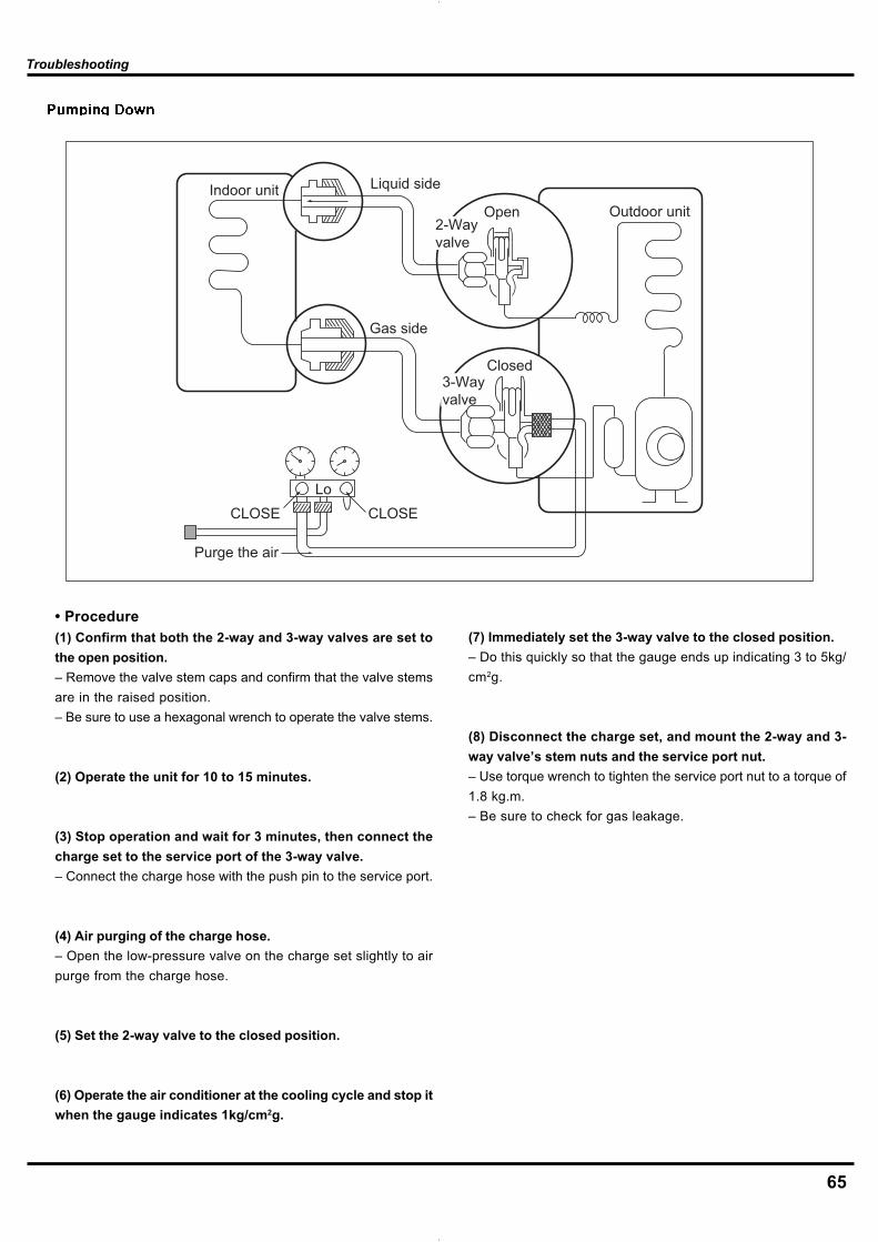
65
Lo
Closed
Purge the air
Outdoor unitIndoor unit Liquid side
Gas side
CLOSE
Open2-Wayvalve
3-Wayvalve
CLOSE
• Procedure(1) Confirm that both the 2-way and 3-way valves are set tothe open position.– Remove the valve stem caps and confirm that the valve stemsare in the raised position.– Be sure to use a hexagonal wrench to operate the valve stems.
(2) Operate the unit for 10 to 15 minutes.
(3) Stop operation and wait for 3 minutes, then connect thecharge set to the service port of the 3-way valve.– Connect the charge hose with the push pin to the service port.
(4) Air purging of the charge hose.– Open the low-pressure valve on the charge set slightly to airpurge from the charge hose.
(5) Set the 2-way valve to the closed position.
(6) Operate the air conditioner at the cooling cycle and stop itwhen the gauge indicates 1kg/cm2g.
(7) Immediately set the 3-way valve to the closed position.– Do this quickly so that the gauge ends up indicating 3 to 5kg/cm2g.
(8) Disconnect the charge set, and mount the 2-way and 3-way valve’s stem nuts and the service port nut.– Use torque wrench to tighten the service port nut to a torque of1.8 kg.m.– Be sure to check for gas leakage.
Troubleshooting
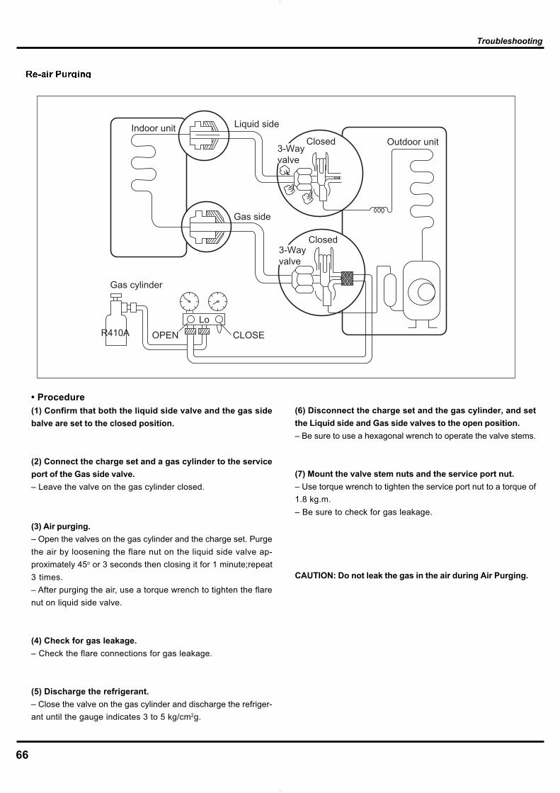
66
Lo
Closed
OPEN
Closed
Gas cylinder
R410A
Outdoor unitIndoor unit Liquid side
Gas side
CLOSE
3-Wayvalve
3-Wayvalve
• Procedure(1) Confirm that both the liquid side valve and the gas sidebalve are set to the closed position.
(2) Connect the charge set and a gas cylinder to the serviceport of the Gas side valve.– Leave the valve on the gas cylinder closed.
(3) Air purging.– Open the valves on the gas cylinder and the charge set. Purgethe air by loosening the flare nut on the liquid side valve ap-proximately 45o or 3 seconds then closing it for 1 minute;repeat3 times.– After purging the air, use a torque wrench to tighten the flarenut on liquid side valve.
(4) Check for gas leakage.– Check the flare connections for gas leakage.
(5) Discharge the refrigerant.– Close the valve on the gas cylinder and discharge the refriger-ant until the gauge indicates 3 to 5 kg/cm2g.
(6) Disconnect the charge set and the gas cylinder, and setthe Liquid side and Gas side valves to the open position.– Be sure to use a hexagonal wrench to operate the valve stems.
(7) Mount the valve stem nuts and the service port nut.– Use torque wrench to tighten the service port nut to a torque of1.8 kg.m.– Be sure to check for gas leakage.
CAUTION: Do not leak the gas in the air during Air Purging.
Troubleshooting
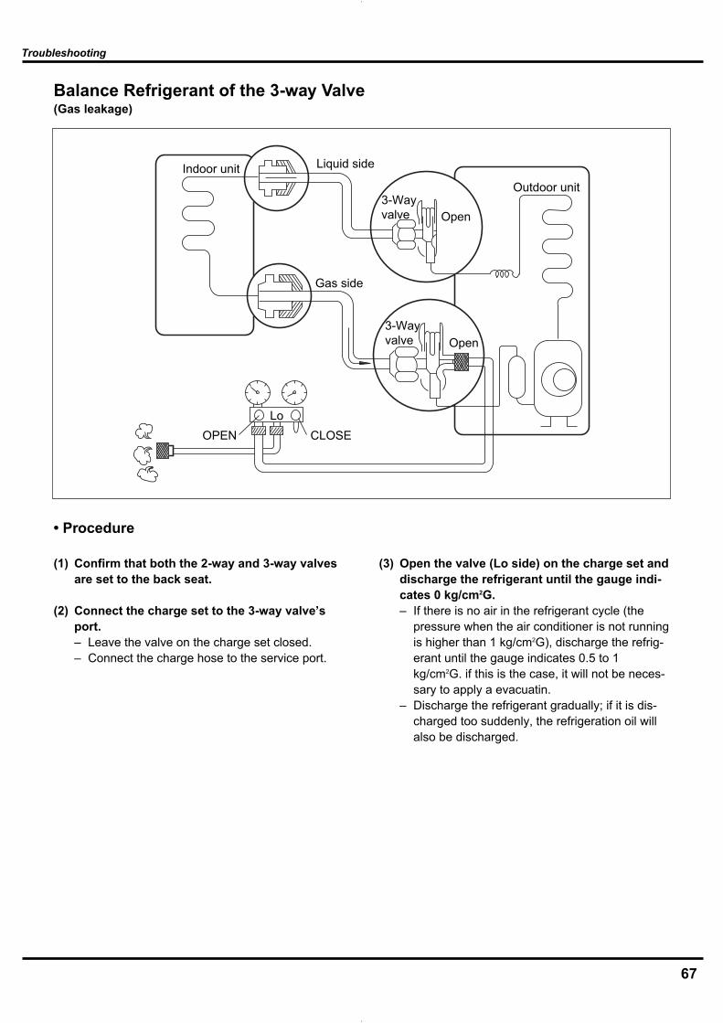
67
Troubleshooting
Balance Refrigerant of the 3-way Valve(Gas leakage)
• Procedure
(1) Confirm that both the 2-way and 3-way valvesare set to the back seat.
(2) Connect the charge set to the 3-way valve’sport.– Leave the valve on the charge set closed.– Connect the charge hose to the service port.
(3) Open the valve (Lo side) on the charge set anddischarge the refrigerant until the gauge indi-cates 0 kg/cm2G.– If there is no air in the refrigerant cycle (the
pressure when the air conditioner is not runningis higher than 1 kg/cm2G), discharge the refrig-erant until the gauge indicates 0.5 to 1kg/cm2G. if this is the case, it will not be neces-sary to apply a evacuatin.
– Discharge the refrigerant gradually; if it is dis-charged too suddenly, the refrigeration oil willalso be discharged.
Lo
Open
Open3-Wayvalve
3-Wayvalve
Gas side
CLOSEOPEN
Outdoor unit
Liquid sideIndoor unit

68
Troubleshooting
Evacuation (All amount of refrigerant leaked)
• Procedure
(1) Connect the vacuum pump to the center hoseof charge set center hose
(2) Evacuation for approximately one hour. – Confirm that the gauge needle has moved
toward -76 cmHg (vacuum of 4 mmHg or less).
(3) Close the valve (Lo side) on the charge set,turn off the vacuum pump, and confirm thatthe gauge needle does not move (approxima-tely 5 minutes after turning off the vacuumpump).
(4) Disconnect the charge hose from the vacuumpump.– Vacuum pump oil.
If the vacuum pump oil becomes dirty ordepleted, replenish as needed.
Lo
Open
Open
Vacuum pump
3-Wayvalve
Outdoor unit
Liquid sideIndoor unit
Gas side
3-Wayvalve
CLOSEOPEN
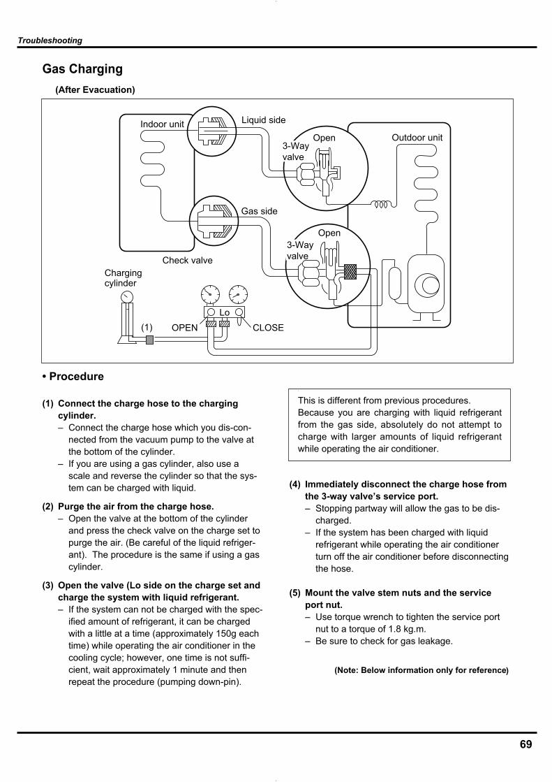
69
Troubleshooting
Gas Charging (After Evacuation)
• Procedure
(1) Connect the charge hose to the chargingcylinder.– Connect the charge hose which you dis-con-
nected from the vacuum pump to the valve atthe bottom of the cylinder.
– If you are using a gas cylinder, also use ascale and reverse the cylinder so that the sys-tem can be charged with liquid.
(2) Purge the air from the charge hose. – Open the valve at the bottom of the cylinder
and press the check valve on the charge set topurge the air. (Be careful of the liquid refriger-ant). The procedure is the same if using a gascylinder.
(3) Open the valve (Lo side on the charge set andcharge the system with liquid refrigerant.– If the system can not be charged with the spec-
ified amount of refrigerant, it can be chargedwith a little at a time (approximately 150g eachtime) while operating the air conditioner in thecooling cycle; however, one time is not suffi-cient, wait approximately 1 minute and thenrepeat the procedure (pumping down-pin).
(4) Immediately disconnect the charge hose fromthe 3-way valve’s service port. – Stopping partway will allow the gas to be dis-
charged.– If the system has been charged with liquid
refrigerant while operating the air conditionerturn off the air conditioner before disconnectingthe hose.
(5) Mount the valve stem nuts and the serviceport nut. – Use torque wrench to tighten the service port
nut to a torque of 1.8 kg.m.– Be sure to check for gas leakage.
\
This is different from previous procedures.Because you are charging with liquid refrigerantfrom the gas side, absolutely do not attempt tocharge with larger amounts of liquid refrigerantwhile operating the air conditioner.
Lo
Chargingcylinder
Outdoor unitIndoor unit Liquid side
Gas side
CLOSE
Open3-Wayvalve
3-Wayvalve
OPEN
Open
Check valve
(1)
(Note: Below information only for reference)

70
Removal Procedure
10. Removal Procedure10.1 Removal Procedure of Indoor Unit
Warning Be sure to wait 10 minutes or more after turningoff all power supplies before disassembling work.
1. External features
2. Removing air filters
If ON/OFF button is kept pushingfor 5 seconds, aforced cooling op-eration wil lbe carried out forapprox. 15minutes.
Pull protrusions on leftand right sides of panelwith fingers and openfront grille all the way.
1
Lift center section of airfilter and disengagehooks.
2
Left and right filters areinterchangeable.
To re-install, insert air filteralong the guide.
Remove air filter bypulling forward.
3
Hooks
Air filter

71
Removal Procedure
3. Opening and shuttingfront panel Support the front panel by onehand, while remove the rotationaxis at the upper center by theother hand.
Pull down horizontal bladeby pulling forward.
1
Left and right filters areinterchangeable.
To re-install, insert air filteralong the guide.
Remove horizontal blade bypulling forward.
2
And pull out the front panelforward to remove.
Hook a finger onto theprojection part providedon the both sides of theunit’s panel and openup the panel to theposition higher than itwill stop.
3
Left Rotary shaft
Rotary shaftRight
Horizontal blade
Remove the front panelfrom the unit.
4

72
Removal Procedure
Left CenterRight
Hooks
4. Opening and closing of service cover
Remove a servicecover mounting screw.Open service coverupward.
1
A switch for field setting isnot provided in particular.
5. Removal of front grille assembly
Screw stoppers inside theflap which were equipped inthe existing models are notprovided.
At the upper part there are 2hooks in the left and theright.
Remove the 3 screws,in the right and the left,which fix the main bodywith the front grille.
1
Disengage the hooks bypressing knobs with ascrewdriver.
screws
screws
Disengage the 3 hookson the upper part.In case that the hooksare not pressed fromabove, remove the frontpanel and then removethe grille while pushingthe hook through aclearance between thefront grille and the heatexchanger.
2
The front grille can beremoved in a manner topull out the upper partforward and lift up thelower part.
3

73
Removal Procedure
6. Remove the Vertical blade
A set of vertical blade has 6 fins as on ASSY.(It is impossible to replace only one fin.)The set of vertical blades is not marked for difference between right and left.
1 Unfasten the hooks at the upper 2 positions.
2 Unfasten the 3 hooks at the shaft mounting part by pressing them with a flat screwdriver.
3 Remove the vertical blade.
Repeat the same procedure to remove the vertical blade on the other side.
Hooks
Hooks
Vertical blade

74
Removal Procedure
7. Remove electrical box
Disconnect the Cableclamp
1
Disconnect theconnection wires.
2
Pay attention to the directionof the retainer of thethermistor so that theretainer will not touch theharness (same as theexisting models.)
Remove Temperature Sen-sor
3
Remove a screw on theterminal board.
4Screw
Earth wire
Take care not to lose the clip of thermistor.
Terminal board
Connectingwires
(R11244)
Heat exchanger thermistor
Clip
(R11268)
Heat exchanger thermistor
The electrical box can beremoved instead ofdisengaging the terminalboard.
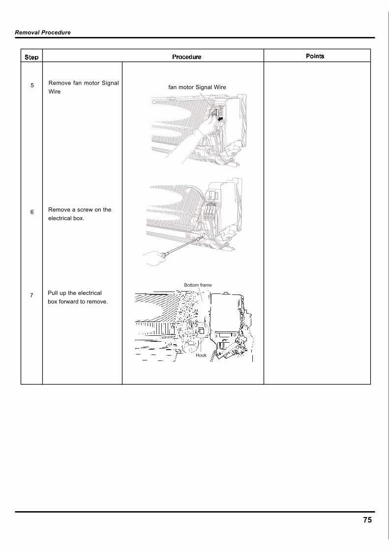
75
Removal Procedure
Remove a screw on theelectrical box.
6
Pull up the electricalbox forward to remove.
7
Remove fan motor SignalWire
5 fan motor Signal Wire
Hook
Bottom frame

76
Removal Procedure
8. Remove the shield plate.
Remove the electrical box according to the “Removal of Electrical Box”.
1 Unfasten the hooks at the upper 2 positions of the shield plate.
2 Unfasten the hook at the lower position, and remove the shield plate (1).
3 Lift the shield plate (2) and unfasten the 2 hooks.
4 Slide the shield plate (2) and remove it.
Hooks
shield plate (1)
Hook
Hooks
Shield plate (2)

77
Removal Procedure
Remove Display PCBSub-Assy.
3
Remove Swing motor.4
Take off Wiring terminal2
Swing motor
Display PCB ASSY
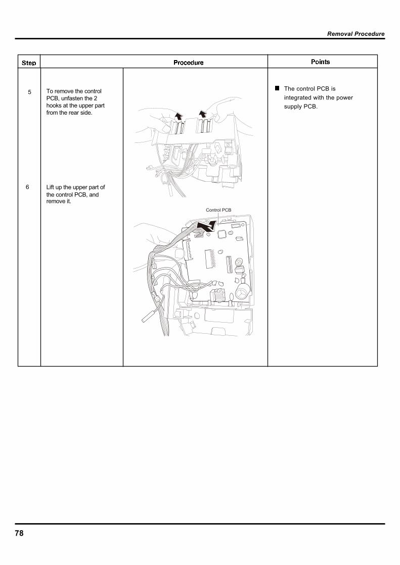
78
Removal Procedure
5 To remove the control PCB, unfasten the 2 hooks at the upper part from the rear side.
6 Lift up the upper part of the control PCB, and remove it.
Control PCB
The control PCB isintegrated with the powersupply PCB.
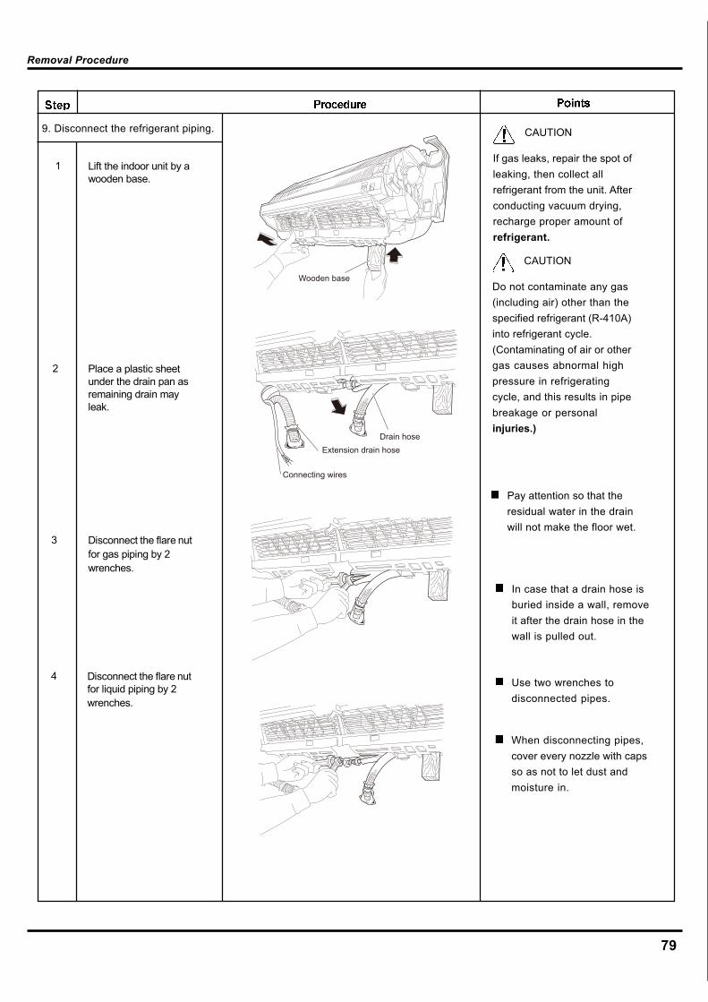
79
Removal Procedure
9. Disconnect the refrigerant piping.
In case that a drain hose isburied inside a wall, removeit after the drain hose in thewall is pulled out.
CAUTION
If gas leaks, repair the spot ofleaking, then collect allrefrigerant from the unit. Afterconducting vacuum drying,recharge proper amount ofrefrigerant.
CAUTION
Do not contaminate any gas(including air) other than thespecified refrigerant (R-410A)into refrigerant cycle.(Contaminating of air or othergas causes abnormal highpressure in refrigeratingcycle, and this results in pipebreakage or personalinjuries.)
When disconnecting pipes,cover every nozzle with capsso as not to let dust andmoisture in.
Wooden base
Drain hoseExtension drain hose
Connecting wires
Pay attention so that theresidual water in the drainwill not make the floor wet.
Use two wrenches todisconnected pipes.
4 Disconnect the flare nut for liquid piping by 2 wrenches.
1 Lift the indoor unit by a wooden base.
2 Place a plastic sheet under the drain pan as remaining drain may leak.
3 Disconnect the flare nut for gas piping by 2 wrenches.
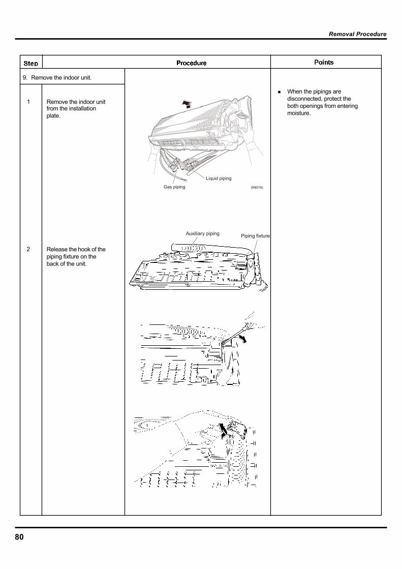
80
Removal Procedure
When the pipings aredisconnected, protect theboth openings from enteringmoisture.
9. Remove the indoor unit.
1 Remove the indoor unitfrom the installationplate.
2 Release the hook of thepiping fixture on theback of the unit.
Gas piping
Liquid piping
(R8019)
Auxiliary piping Piping fixture

81
Removal Procedure
Loosen the 2 screws,in the right and the left,which fix the EvaporatorAssy.
3
4 Widen the auxiliary piping to the extent of 10°~20°.
5 Pull the heat exchanger to the front side to undo the hooks completely, and then lift it.
Auxiliary piping
Heat exchanger
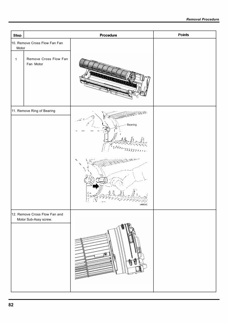
82
Removal Procedure
10. Remove Cross Flow Fan FanMotor
11. Remove Ring of Bearing
Bearing
Remove Cross Flow FanFan Motor
1
12. Remove Cross Flow Fan andMotor Sub-Assy screw.
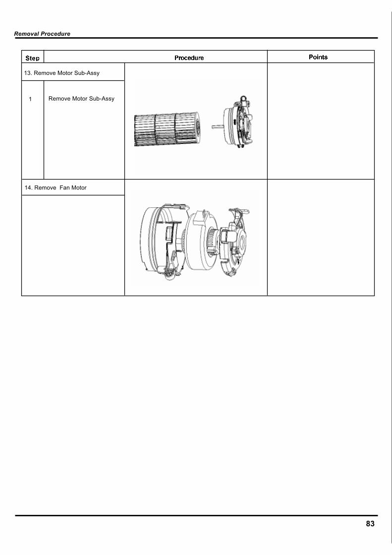
83
Removal Procedure
13. Remove Motor Sub-Assy
14. Remove Fan Motor
Remove Motor Sub-Assy1
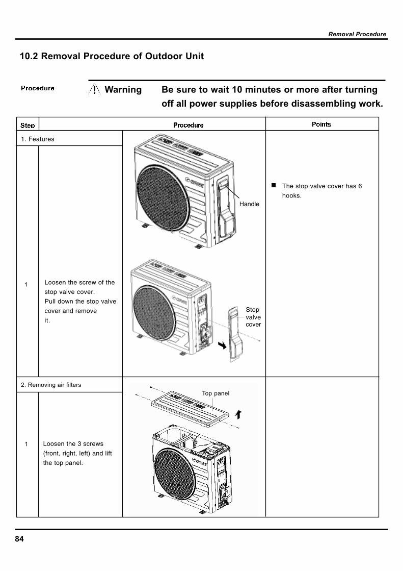
84
10.2 Removal Procedure of Outdoor Unit
Warning Be sure to wait 10 minutes or more after turningoff all power supplies before disassembling work.
1. Features
The stop valve cover has 6
hooks.
Loosen the screw of the
stop valve cover.
Pull down the stop valve
cover and remove
it.
1
Loosen the 3 screws
(front, right, left) and lift
the top panel.
1
Handle
Stopvalvecover
2. Removing air filtersTop panel
Removal Procedure

85
Loosen the 1 screws
and remove the
discharge grille.
2
Loosen the 5 screws of
the front panel.
3
1
Remove the fan motor The screw has reverse
winding.
Remove the propeller
fan.
Front panel.
Propeller fan.
Lift the front panel andremove it while pushing theright side panel inwards.Step Procedure Points
Removal Procedure
Remove the 5 screws from the edge between right-side
board and condenser and from valve. Lift to remove the right-side board subassembly.
Remove the screws of the fan bywren and then remove the
fan .ch
axial flow
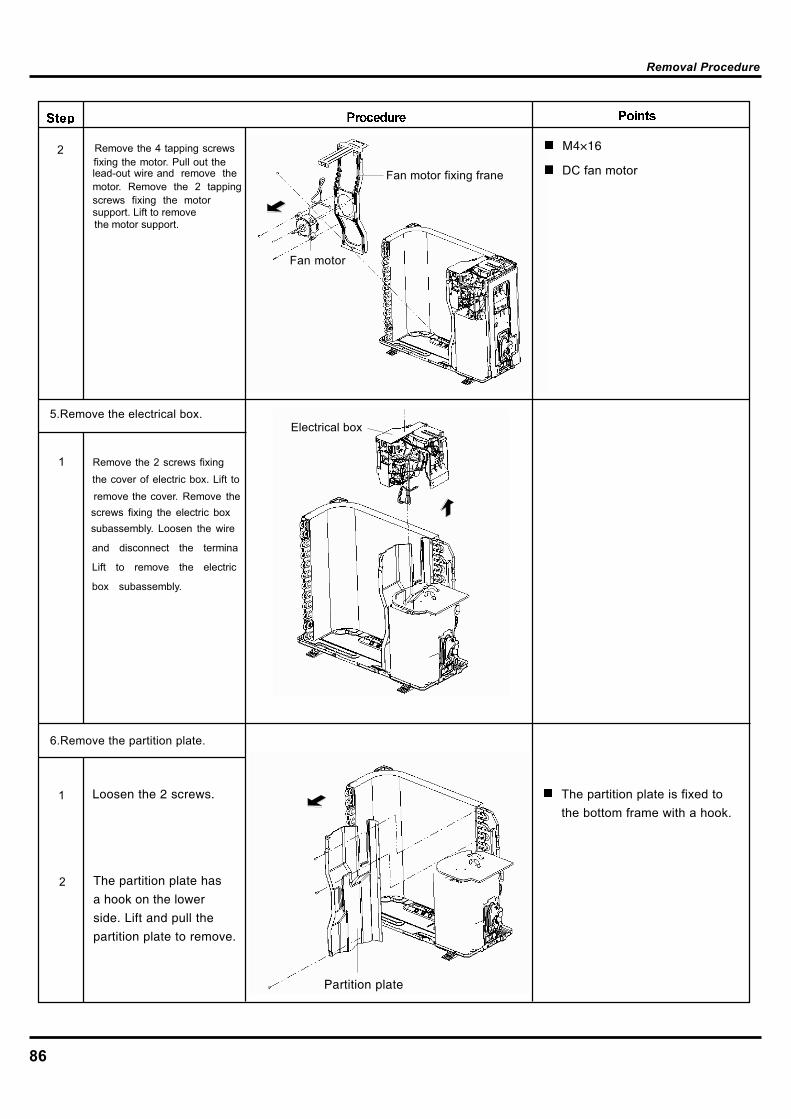
86
2
DC fan motor
M4×16
1
Fan motor
Fan motor fixing frane
Electrical box5.Remove the electrical box.
6.Remove the partition plate.
1 Loosen the 2 screws.
2 The partition plate has
a hook on the lower
side. Lift and pull the
partition plate to remove.
Partition plate
The partition plate is fixed tothe bottom frame with a hook.
Removal Procedure
Remove the 4 tapping screws fixing the motor. Pull out the lead-out wire and remove the motor. Remove the 2 tapping screws fixing the motor support. Lift to remove the motor support.
Remove the 2 screws fixingthe cover of electric box. Lift to
remove the cover. Remove the screws fixing the electric box subassembly. Loosen the wire
and disconnect the termina
Lift to remove the electric
box subassembly.
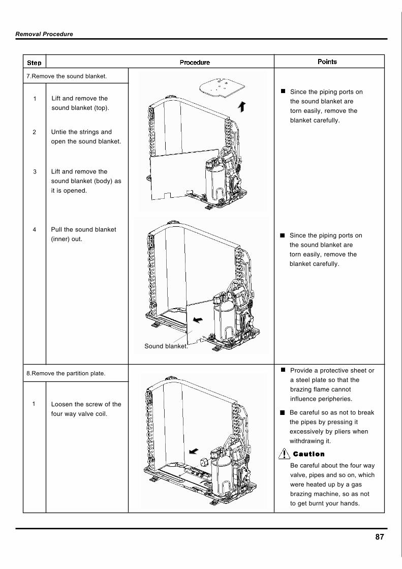
87
7.Remove the sound blanket.
Lift and remove the
sound blanket (top).
1
Untie the strings and
open the sound blanket.
2
3
1
8.Remove the partition plate.
Since the piping ports on
the sound blanket are
torn easily, remove the
blanket carefully.
Sound blanket.
Lift and remove the
sound blanket (body) as
it is opened.
4 Pull the sound blanket
(inner) out. Since the piping ports on
the sound blanket are
torn easily, remove the
blanket carefully.
Loosen the screw of the
four way valve coil.
Provide a protective sheet or
a steel plate so that the
brazing flame cannot
influence peripheries.
Be careful so as not to break
the pipes by pressing it
excessively by pliers when
withdrawing it.
CautionCautionCautionCautionCaution
Be careful about the four wayvalve, pipes and so on, whichwere heated up by a gasbrazing machine, so as notto get burnt your hands.
Removal Procedure

88
4
1
2
3
Removal Procedure
Solder off the welding spot of capillary and valve and outlet pipe of condenser.
Remove the 2 screws fixing thegas valve. Solder off the weldspot connecting gas valve and
air return pipe and remove thegas valve.(Note: it is necessary to warp
the gas valve when soldering off the welding spot.)
Remove the 2 screws fixing liquid valve. Solder off the welding spot connecting liquid
valve and remove the liquid valve.
Solder off the pipe connected
with the compressor.
Remove compressor
Remove the 3 footingscrews of the compressorand remove the compressor.

89
HEAT EXCHANGE(EVAPORATOR)
HEAT EXCHANGE(CONDENSER)
COMPRESSOR CAPLIARY
STRAINER
PUMP 槽
11. Care and Cleaning11 Cleaning Refrigeration System In addition to replacement of compressor, capillary and strainer, the whole refrigeration system
shall be completely cleaned, as the refrigerant in the system is contaminated by a lot of acid
oxydum generated from insulation breakdown, turn-to-turn short circuit or burning out of winding
of compressor’s motor during malfunction.
The refrigeration oil in the mild-contaminated refrigeration system shall be limpid when
discharging from the process pipe of compressor. It shall be faint yellow (normally white) if
testing by lacmus paper. While severe- contaminated, it is black and the testing lacmus paper
becomes red 5min later.
The abluent R113 is used to clean the system.
Confirm the contamination degree by checking color and smell of refrigerant before cleaning
the system, as shown in the figure.
Check the refrigeration oil for impurity by discharging a little of oil from the process pipe of
compressor.
Cleaning Procedure:
1. Charge the abluent R113 into the fluid bath. Start up the pump to clean the system about
1hr if mid-contaminated or 3-4hr if severe-contaminated. In order to avoid blockage of strainer,
the abluent and the strainer shall be replaced after long-time cleaning.
2. The abluent after cleaning of the system can be recovered from liquid pipe and it can be
reused after processing.
3. The refrigeration pipeline should be blown off by nitrogen and dried after cleaning.
Disconnect the parts in the broken frame with the pipeline and install blind plates on ring
flanges of liquid suction and pumping pipes before drying process. In order to quickly dry the
system, make vacuum pumping while blow off hot wind to external refrigeration pipeline.
Afterwards, reassemble the pipeline (charge nitrogen while welding) and replace the
compressor and strainer.
Cautions:
1. In order to avoid leakage of abluent, pressure hose should be adopted and joint parts
should be tightly wrapped.
2. The expansion valve adopted by the unit shall be replaced by by-pass pipe.
3. Remove the moisture contained in the refrigeration system.
4. Use nitrogen to blow off the acid generated from burning out of compressor
11.2 Cleaning of Heater Exchanger In order to improve energy efficiency, the heater exchanger, especially the condenser in the outdoor
unit, should be cleaned after operation of several years.
BATH

Willis Air Conditioning
Add:2105 chemin de la cote de liesse,Montréal, QC H4N 2M5 Canada.Tel: 514 735 7147