service manual - klimasbt.com©khűtős_rendszerek/1... · the daikin ewa(y)q005~007a*v3 air to...
TRANSCRIPT

Service ManualMINI-CHILLEREWA(Y)Q005~007A*V3
ESIE06-04
ESIE06-04.book Page 1 Thursday, November 2, 2006 11:01 AM

ESIE06-04.book Page 2 Thursday, November 2, 2006 11:01 AM
ESIE06-04
3
4
5
1Table of Contents
ESIE06-04.book Page i Thursday, November 2, 2006 11:01 AM
1 Introduction
1.1 About This Manual .................................................................................. i–i
Part 1System Outline
1 General Outline: Mini-chiller
1.1 What Is in This Chapter? ........................................................................ 1–31.2 EWA(Y)Q005~007A*V3: Outlook and Dimensions................................. 1–41.3 EWA(Y)Q005~007A*V3: Installation and Service Space........................ 1–5
2 Specifications
2.1 What Is in This Chapter? ........................................................................ 1–72.2 EWA(Y)Q005~007A*V3 .......................................................................... 1–8
3 Functional Diagrams
3.1 What Is in This Chapter? ........................................................................ 1–113.2 Pipe Connection Diameters .................................................................... 1–12
4 Piping Diagrams
4.1 What Is in This Chapter? ........................................................................ 1–134.2 EWA(Y)Q005~007A*V3 ......................................................................... 1–14
5 Switch Box Layout
5.1 What Is in This Chapter? ........................................................................ 1–175.2 EWA(Y)Q005~007A*V3 (Outdoor).......................................................... 1–185.3 EWA(Y)Q005~007A*V3 (Hydro-kit) ........................................................ 1–20
Table of Contents i
ESIE06-04
3
1
4
5
ESIE06-04.book Page ii Thursday, November 2, 2006 11:01 AM
6 Wiring Diagrams
6.1 What Is in This Chapter? ......................................................................... 1–216.2 EWA(Y)Q005~007A*V3........................................................................... 1–22
7 PCB Layout
7.1 What Is in This Chapter? ......................................................................... 1–257.2 EWA(Y)Q005~007A*V3 (Outdoor) .......................................................... 1–267.3 EWA(Y)Q005~007A*V3 (Hydro-kit) ......................................................... 1–30
Part 2Functional Description
1 General Functionality
1.1 What Is in This Chapter? ......................................................................... 2–31.2 Preheating Operation............................................................................... 2–41.3 Four Way Valve Switching ....................................................................... 2–51.4 Freeze-up Protection Control................................................................... 2–6
2 Hydro-kit Functional Concept
2.1 What Is in This Chapter? ......................................................................... 2–72.2 Defrost Control ........................................................................................ 2–82.3 Forced Operation Model .......................................................................... 2–9
3 Outdoor Unit Functional Concept
3.1 What Is in This Chapter? ......................................................................... 2–113.2 Frequency Principle ................................................................................. 2–123.3 Frequency Control ................................................................................... 2–143.4 Controls at Mode Changing / Start-up ..................................................... 2–163.5 Discharge Pipe Temperature Control ...................................................... 2–173.6 Input Current Control ............................................................................... 2–183.7 Heating Peak-cut Control......................................................................... 2–193.8 Fan Control .............................................................................................. 2–203.9 Liquid Compression Protection Function 2 .............................................. 2–213.10 Low Hz High Pressure Limit .................................................................... 2–223.11 Electronic Expansion Valve Controll ........................................................ 2–233.12 Malfunctions............................................................................................. 2–27
ii Table of Contents

ESIE06-04
3
4
5
1
ESIE06-04.book Page iii Thursday, November 2, 2006 11:01 AM
Part 3Troubleshooting
1 Troubleshooting
1.1 What Is in This Chapter? ........................................................................ 3–31.2 Procedure of Self-Diagnosis by Remote Controller ................................ 3–41.3 Fault-diagnosis by Remote Controller..................................................... 3–51.4 Overview of Error Codes......................................................................... 3–6
2 Error Codes: Hydro-kit
2.1 What Is in This Chapter? ........................................................................ 3–72.2 “A1” Hydro-kit PCB Abnormality............................................................... 3–82.3 “A5” Freeze-up Protection Control or High Pressure Control .................. 3–92.4 “C4, 81, 80” Thermistor or Related Abnormality (Hydro-kit) ...................... 3–10
3 Error Codes: Outdoor Units
3.1 What Is in This Chapter? ........................................................................ 3–113.2 “E1” Outdoor Unit PCB Abnormality ......................................................... 3–123.3 “E5” OL Activation (Compressor Overload)............................................. 3–133.4 “E6” Compressor Lock............................................................................. 3–153.5 “E7” DC Fan Lock .................................................................................... 3–163.6 “E8” Input Over Current Detection........................................................... 3–173.7 “EA” Four Way Valve Abnormality ........................................................... 3–193.8 “F3” Discharge Pipe Temperature Control............................................... 3–213.9 “F6” High Pressure Control in Cooling..................................................... 3–233.10 “H0” Compressor Sensor System Abnormality........................................ 3–253.11 “H6” Compressor Startup Failure ............................................................ 3–273.12 “H8” CT or Related Abnormality .............................................................. 3–293.13 “P4, J3, J6, H9” Thermistor or Related Abnormality (Outdoor Unit) .......... 3–313.14 “L3” Switch Box Temperature Rise.......................................................... 3–333.15 “L4” Radiation Fin Temperature Rise...................................................... 3–353.16 “L5” Output Over Current Detection ........................................................ 3–37
4 Error Codes: System Malfunctions
4.1 What Is in This Chapter? ........................................................................ 3–414.2 “U0” Insufficient Gas................................................................................ 3–424.3 “U2” Low-voltage Detection or Over-voltage Detection ........................... 3–444.4 “U4” Signal Transmission Error (between Hydro-kit and
Outdoor Units)......................................................................................... 3–454.5 “U7” Malfunction of Transmission between Remote Controller
and Control box....................................................................................... 3–47
Table of Contents iii

ESIE06-04
3
1
4
5
ESIE06-04.book Page iv Thursday, November 2, 2006 11:01 AM
5 Additional Checks for Troubleshooting
5.1 What Is in This Chapter? ......................................................................... 3–495.2 Fan Motor Connector Output Check ....................................................... 3–505.3 Electronic Expansion Valve Check .......................................................... 3–515.4 Four Way Valve Performance Check....................................................... 3–525.5 Thermistor Resistance Check.................................................................. 3–535.6 Installation Condition Check .................................................................... 3–555.7 Discharge Pressure Check ...................................................................... 3–565.8 Outdoor Unit Fan System Check (With DC Motor) .................................. 3–575.9 Power Supply Waveforms Check ............................................................ 3–585.10 Inverter Units Refrigerant System Check................................................. 3–595.11 Capacitor Voltage Check ......................................................................... 3–605.12 Power Transistor Check .......................................................................... 3–615.13 Main Circuit Electrolytic Capacitor Check................................................ 3–625.14 Turning Speed Pulse Input on the Outdoor Unit PCB Check .................. 3–635.15 “Inverter Checker” Check......................................................................... 3–64
Part 4Commissioning and Test Run
1 Pre-Test Run Checks
1.1 What Is in This Chapter? ......................................................................... 4–31.2 Test Run Checks for Water Pipework...................................................... 4–41.3 General Test Run Checks ....................................................................... 4–7
2 Field settings
2.1 What Is in This Chapter? ......................................................................... 4–92.2 How to Change the Field Settings with the Wired Remote Controller ..... 4–102.3 Overview of the Field Settings by Remote Control .................................. 4–122.4 Field Setting by Dip Switches from Hydro-kit........................................... 4–17
3 Operation Range and Test Operation
3.1 Operation Range ..................................................................................... 4–203.2 Test Operation ......................................................................................... 4–213.3 External Static Pressure Chart ................................................................ 4–22
iv Table of Contents

ESIE06-04 Introduction
ESIE06-04.book Page i Thursday, November 2, 2006 11:01 AM
Part 0
3
4
5
1 Introduction
1.1 About This Manual
Target group This service manual is intended for and should only be used by qualified engineers.
Purpose of this manual
This service manual contains all the information you need to carry out the necessary repair and maintenance tasks for the EWA(Y)Q005~007A*V3.
EWA(Y)Q005~007A*V3
The Daikin EWA(Y)Q005~007A*V3 air to water unit:
m Is designed for outdoor installation.
m Is used for cooling and heating applications.
m Is available in three standard sizes with nominal cooling capacities ranging from 5 kW to 7 kW.
Before starting Before starting up the unit for the first time, make sure it has been properly installed. ‘‘Pre-Test Run Checks” on page 4-3.
i

Introduction ESIE06-04
3
1
4
5
ESIE06-04.book Page ii Thursday, November 2, 2006 11:01 AM
ii

ESIE06-04
4
3
4
5
1
ESIE06-04.book Page 1 Thursday, November 2, 2006 11:01 AM
Part 1System Outline
What is in this part? This part contains the following chapters:
Chapter See page
1–General Outline: Mini-chiller 1–3
2–Specifications 1–7
3–Functional Diagrams 1–11
4–Piping Diagrams 1–13
5–Switch Box Layout 1–17
6–Wiring Diagrams 1–21
7–PCB Layout 1–25
Part 1 – System Outline 1–1

ESIE06-04
3
11
5
ESIE06-04.book Page 2 Thursday, November 2, 2006 11:01 AM
1–2 Part 1 – System Outline
ESIE06-04 General Outline: Mini-chiller
1
ESIE06-04.book Page 3 Thursday, November 2, 2006 11:01 AM
Part 1
3
4
5
1 General Outline: Mini-chiller
1.1 What Is in This Chapter?
Introduction This chapter contains the following information on the Mini-chiller:
m Outlook and dimensions
m Installation and service space
m Components
General outline This chapter contains the following general outlines:
General outline See page
1.2–EWA(Y)Q005~007A*V3: Outlook and Dimensions 1–4
1.3–EWA(Y)Q005~007A*V3: Installation and Service Space 1–5
Part 1 – System Outline 1–3

General Outline: Mini-chiller ESIE06-04
3
11
4
5
ESIE06-04.book Page 4 Thursday, November 2, 2006 11:01 AM
1.2 EWA(Y)Q005~007A*V3: Outlook and Dimensions
Outlook and dimensions
The illustration below shows the outlook and the dimensions of the unit (mm).
Components The table below contains the different components of the unit.
13
15
11 12 14
124356
10
9
8
7
330 15
137 69
12
125
154 x holes foranchor bolts(M8 pr M10)
580
1170
805
360
149
1590
1189
drain outlet ∅18
323
80
367
g p
example ofposition
1" Male BSP
No. Component
1 Water inlet 1” MBSP
2 Water outlet 1” MBSP
3 Remocon cable intake
4 Power supply intake
5 Drain and fill valve
6 Blow off valve
7 Pump + switch for speed setting
8 Expansion vessel service valve
9 Pressure gauge
10 Water filter
11 Air purge
12 Main switch
13 Switchbox connection terminals
14 Outdoor air thermistor
15 Shut off valve (delivered with unit)
1–4 Part 1 – System Outline

ESIE06-04 General Outline: Mini-chiller
3
1
4
5
ESIE06-04.book Page 5 Thursday, November 2, 2006 11:01 AM
1.3 EWA(Y)Q005~007A*V3: Installation and Service Space
Installing near a wall or obstacle
m Where a wall or other obstacle is in the path of the outdoor unit air intake or exhaust airflow, follow the installation guidelines below.
m For any of the installation patterns below, the wall height on the exhaust side should be 1200 mm or less.
Wall facing one side (unit: mm)
Walls facing two sides (unit: mm)
Walls facing three sides (unit: mm)
Remark: m Back to back: 300 mm
m Front to front: 5000 mm
>100 >350
<1
200
>50>50
>350>100
>100
>350>50
Part 1 – System Outline 1–5

General Outline: Mini-chiller ESIE06-04
3
11
4
5
ESIE06-04.book Page 6 Thursday, November 2, 2006 11:01 AM
1–6 Part 1 – System Outline

ESIE06-04 Specifications
1
ESIE06-04.book Page 7 Thursday, November 2, 2006 11:01 AM
Part 1
3
4
5
2 Specifications
2.1 What Is in This Chapter?
Introduction This chapter contains the following information:
m Technical specifications
m Electrical specifications
Mini-chiller This chapter contains the following specifications:
Specifications See page
2.2–EWA(Y)Q005~007A*V3 1–8
Part 1 – System Outline 1–7

Specifications ESIE06-04
3
11
4
5
ESIE06-04.book Page 8 Thursday, November 2, 2006 11:01 AM
2.2 EWA(Y)Q005~007A*V3
Technical specifications
The table below contains the technical specifications.
Specification EWAQ005AAV3P EWAQ006AAV3P EWAQ007AAV3P EWYQ005AAV3P EWYQ006AAV3P EWYQ007AAV3P
Capacity Cooling (min-nom-max) (1) 4.01-5.2-5.2 kW 4.01-6.0-6.0 kW 4.01-7.1-7.1 kW 4.01-5.2-5.2 kW 4.01-6.0-6.0 kW 4.01-7.1-7.1 kW
Heating (min-nom-max) (2) - 4.5-6.1-7.27 kW 4.5-6.8-8.58 kW 4.5-8.2-9.18 kW
Heating (min-nom-max) (3) - 4.09-5.85-6.83 kW 4.09-6.35-8.13 kW 4.09-7.75-8.73 kW
Input Cooling (nom) 1.89 kW 2.35 kW 2.95 kW 1.89 kW 2.35 kW 2.95 kW
Heating (nom) (2) - - - 1.60 kW 1.84 kW 2.36 kW
Heating (nom) (3) - - - 1.97 kW 2.24 kW 2.83 kW
EER & COP EER 2.75 2.55 2.41 2.75 2.55 2.41
COP (2) - - - 3.81 3.70 3.47
COP (3) - - - 2.87 2.83 2.74
Casing Colour Ivory white
Material Polyester painted galvanised steel
Dimensions Unit - height 805 mm
Unit - width 1190 mm
Unit - depth 360 mm
Unit with packing - height 915 mm
Unit with packing - width 1265 mm
Unit with packing - depth 442 mm
Weight Machine weight 100 kg
Operating weight 104 kg
Gross weight 108 kg
Water heat exchanger Type Brazed plate
Filter - Type Brass Y-strainer
Filter - Diameter perforations 1 mm
Minimum water volume in the system
10 l
Water flow rate - min. 12 l/min 12 l/min 12 l/min 12 l/min 12 l/min 12 l/min
Nominal water flow - cooling 14.9 l/min 17.2 l/min 20.4 l/min 14.9 l/min 17.2 l/min 20.4 l/min
Nominal water flow - heating - - - 17.5 l/min 19.5 l/min 23.5 l/min
Insulation material PE foam
Model ACH30-48
Model quantity 1
Air heat exchanger Type Tube type
Rows 2
Stages 32
Fin pitch 1.8 mm
Pump Type Water cooled
Quantity 1
Model RS 25/7 3 PL 130 3
Nominal static height unit - cooling
49.4 kPa 45.1 kPa 38.3 kPa 49.4 kPa 45.1 kPa 38.3 kPa
Nominal static height unit - heating
- - - 44.5 kPa 40.3 kPa 30.7 kPa
Hydraulic components Antifreeze heater (optional) 75 W
Expansion vessel - volume 6 l
Expansion vessel - pre-pressure 1 bar
Water filter 1” inch
Safety valve 3 bar
1–8 Part 1 – System Outline

ESIE06-04 Specifications
3
1
4
5
ESIE06-04.book Page 9 Thursday, November 2, 2006 11:01 AM
Fan Type Propeller
Nominal air flow - cooling 48.9 m³/min 50.9 m³/min 59.4 m³/min 48.9 m³/min 50.9 m³/min 59.4 m³/min
Nominal air flow - heating - - - 45 m³/min 46.3 m³/min 52.2 m³/min
Model - Quantity 1
Model - Speed - cooling 780 rpm 810 rpm 940 rpm 780 rpm 810 rpm 940 rpm
Model - Speed - heating - - - 720 rpm 740 rpm 830 rpm
Model - Motor output 53 W
Model - Discharge direction Horizontal
Compressor Type Hermetically sealed swing compressor
Refrigerant oil type FVC50K
Refrigerant oil charge 0.75 l 0.75 l 0.75 l 0.75 l 0.75 l 0.75 l
Model 2YC63BXD#C 2YC63BXD#C 2YC63BXD#C 2YC63BXD#C 2YC63BXD#C 2YC63BXD#C
Model - Quantity 1
Sound level Sound power - cooling 63 dBA 64 dBA 66 dBA 63 dBA 64 dBA 66 dBA
Sound pressure (front of unit - free field condition - 1 m) :
- cooling 47 dBA 47 dBA 53 dBA 47 dBA 47 dBA 53 dBA
- heating - - - 48 dBA 48 dBA 52 dBA
Refrigerant circuit Refrigerant type R410A
Refrigerant charge 1.7 kg
No. of circuits 1
Refrigerant control Inverter
Piping connections Water heat exchanger inlet/out-let
1” MBSP
Water heat exchanger drain Hose nipple 1/2” FBSP
NOTES (1) Tamb 35°C - LWE 7°C (DT = 5°C)
(2) DB/WB 7°C/6°C - LWC 35°C (DT = 5°C)
(3) DB/WB 7°C/6°C - LWC 45°C (DT = 5°C)
Specification EWAQ005AAV3P EWAQ006AAV3P EWAQ007AAV3P EWYQ005AAV3P EWYQ006AAV3P EWYQ007AAV3P
Part 1 – System Outline 1–9

Specifications ESIE06-04
3
11
4
5
ESIE06-04.book Page 10 Thursday, November 2, 2006 11:01 AM
Electrical specifications
The table below contains the electrical specifications.
Specification EWAQ005AAV3P EWAQ006AAV3P EWAQ007AAV3P EWYQ005AAV3P EWYQ006AAV3P EWYQ007AAV3P
Power supply Name V3
Phase 1~
Frequency 50 Hz
Voltage 230 V
Voltage tolerance - min. 10 %
Voltage tolerance - max. 10 %
Unit
Zmax list No requirements
Maximum running current 17.3 A 19 A
Recommended fuses according to IEC standard 269-2
20
Fans Quantity 1
Phase 1~
Voltage 230 V
Pump Phase 1~
Power input 0.13 kW
Speed 1050 / 2250 / 2450 rpm
Voltage 230 V
Maximum running current 0.58 A
Evaporator heater tape Supply voltage 230 V
Capacity 75 W
Voltage tolerance min. 10 %
Voltage tolerance max. 10 %
Recommended fuses (1) 20 A 20 A 20 A 25 A 25 A 25 A
NOTE (1) Fuse value valid for complete unit
1–10 Part 1 – System Outline

ESIE06-04 Functional Diagrams
1
ESIE06-04.book Page 11 Thursday, November 2, 2006 11:01 AM
Part 1
3
4
5
3 Functional Diagrams
3.1 What Is in This Chapter?
Introduction This chapter contains the following information:
m Pipe connection diameters.
Functional diagrams
This chapter contains the following functional diagrams:
Functional diagram See page
3.2–Pipe Connection Diameters 1–12
Part 1 – System Outline 1–11

Functional Diagrams ESIE06-04
3
11
4
5
ESIE06-04.book Page 12 Thursday, November 2, 2006 11:01 AM
3.2 Pipe Connection Diameters
Hydro-kit + water side
The table below contains the water inlet/outlet connection diameters.
1: MBSP = male British standard pipe
Model ∅ Gas pipe (flare) ∅ Liquid pipe (flare)
EWA(Y)Q005~007A*V3 1 inch (MBSP)1 1 inch (MBSP)1
1–12 Part 1 – System Outline
ESIE06-04 Piping Diagrams
1
ESIE06-04.book Page 13 Thursday, November 2, 2006 11:01 AM
Part 1
3
4
5
4 Piping Diagrams
4.1 What Is in This Chapter?
Introduction This chapter contains the following information:
m Piping diagrams
Piping diagrams This chapter contains the following piping diagrams:
Functional diagram See page
4.2–EWA(Y)Q005~007A*V3 1–14
Part 1 – System Outline 1–13

Piping Diagrams ESIE06-04
3
11
4
5
ESIE06-04.book Page 14 Thursday, November 2, 2006 11:01 AM
4.2 EWA(Y)Q005~007A*V3
11
10
9
8 7
6
442
1
5
3
6
RE
FR
.S
IDE
WA
TE
R S
IDE
FIE
LDIN
STA
LLA
TIO
N
FIE
LDIN
STA
LLA
TIO
N
R4T t >
R1Tt >
DR
AIN
1–14 Part 1 – System Outline

ESIE06-04 Piping Diagrams
3
1
4
5
ESIE06-04.book Page 15 Thursday, November 2, 2006 11:01 AM
Components The table below contains the different components of the functional diagrams.
No. Name
1 Expansion vessel
2 Pressure gauge
3 Pump
4 Drain valve
5 Safety valve
6 Shut off valve
7 Outlet
8 Inlet
9 Flowswitch
10 Air purge
11 Filter
Part 1 – System Outline 1–15

Piping Diagrams ESIE06-04
3
11
4
5
ESIE06-04.book Page 16 Thursday, November 2, 2006 11:01 AM
1–16 Part 1 – System Outline
ESIE06-04 Switch Box Layout
1
ESIE06-04.book Page 17 Thursday, November 2, 2006 11:01 AM
Part 1
3
4
5
5 Switch Box Layout
5.1 What Is in This Chapter?
Introduction This chapter shows the switch box components.
Mini-chiller This chapter contains the following switch box layouts:
Switch box layout See page
5.2–EWA(Y)Q005~007A*V3 (Outdoor) 1–18
5.3–EWA(Y)Q005~007A*V3 (Hydro-kit) 1–20
Part 1 – System Outline 1–17

Switch Box Layout ESIE06-04
3
11
4
5
ESIE06-04.book Page 18 Thursday, November 2, 2006 11:01 AM
5.2 EWA(Y)Q005~007A*V3 (Outdoor)
The illustration below shows the outdoor switch box 1 layout:
Item Description
PCB1 Printed circuit board (main)
L1R Reactor coil
1–18 Part 1 – System Outline

ESIE06-04 Switch Box Layout
3
1
4
5
ESIE06-04.book Page 19 Thursday, November 2, 2006 11:01 AM
The illustration below shows the outdoor switch box 2 layout:
Item Description
PCB2 Printed circuit board
X1M Terminal strip: Power supply
X2M Terminal strip: Communication
Part 1 – System Outline 1–19

Switch Box Layout ESIE06-04
3
11
4
5
ESIE06-04.book Page 20 Thursday, November 2, 2006 11:01 AM
5.3 EWA(Y)Q005~007A*V3 (Hydro-kit)
The illustration below shows the Hydro-kit switch box layout:
Item Description
A1P Printed circuit board
S1M Main switch
TR1 Transformer (220 V/24 V)
X3M Terminal strip
1–20 Part 1 – System Outline
ESIE06-04 Wiring Diagrams
1
ESIE06-04.book Page 21 Thursday, November 2, 2006 11:01 AM
Part 1
3
4
5
6 Wiring Diagrams
6.1 What Is in This Chapter?
Introduction This chapter contains the wiring diagrams of the Mini-chiller.
Mini-chiller: This chapter contains the following wiring diagrams:
Wiring diagram See page
6.2–EWA(Y)Q005~007A*V3 1–22
Part 1 – System Outline 1–21
Wiring Diagrams ESIE06-04
3
11
4
5
ESIE06-04.book Page 22 Thursday, November 2, 2006 11:01 AM
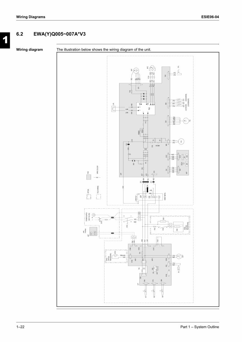
6.2 EWA(Y)Q005~007A*V3
Wiring diagram The illustration below shows the wiring diagram of the unit.
12
34
ON OFF
SS2
13
24
BLK
BRN
ORG
PNK GR
Y
BLK
BRN
WHTWHT/RED 3
1
BRNBLU
BLUBRN
POW
ER S
UPPL
Y
X15A 1
3
SA2
GRN
Y1EM
Y1R
(CON
DENS
OR)
(DIS
CHAR
GE)
(OUT
DOOR
)R1
TBLK
R2Tt
GRY
BLU
21X8
AR4
Tt
S40
15 BLK
BLK
M1F
M1C
BLU
YLW
RED
X11A
BLU
YLW
REDW
HTOR
GBR
NBL
U
RED
OP10
(OPT
ION
HEAT
ERTA
PE)
L
32
1
S1M
321
X2M
X1M N
REDBRNBLUORGYLWWHT
BLKBLK
BLUBLUBLUBLUBLU
GRNWHTBLKRED
3S8
01
1
S90
66
SW4
A3P
LED
A
SW1
S2
51
S52
S102
15
S20
15
1S1
01S5
11
51
8
X10A
254
1X1
8A
Q1DI
230V
1N~
50Hz
NL
21
S1L
X4A
M1P
1
X14A KP
R
t
R3T
tR3
T
R1T
t
X7A
X5A
user
inter
face
P2P1R1
T
X2A
X19A
TR1
X1A
M
1 1 22
1 5
OPTI
ON
FIEL
D W
IRIN
G
PCB
BRN
WIR
E CO
LOUR
BLK
WHT
BRN
BLU
RED
GRN/
YLW
1S1
0
AC2
AC1
FU1
E1GR
N
E2
Z1C
MRM
10
MRM
20
1 2
98
6(P)
7(N)
5 4 3
HR1
HR2
MRC/W
FU2
V6V1
1
V3 V5
PM1
A4P
WHT
WHT
L1R
SHEE
T M
ETAL
M
M 3
FU3
S70
17
U V W
++
+
FU1
A2P
A1P
Q1L
Z2C
Z4C
Z3C
K4R
X17A
1 7
BLK
1 5
K1M
7
E6H
6
E5H
OP10
(OPT
ION
HEAT
ERTA
PE)
K1M
4 3
FU2
1–22 Part 1 – System Outline
ESIE06-04 Wiring Diagrams
3
1
4
5
ESIE06-04.book Page 23 Thursday, November 2, 2006 11:01 AM
Notes
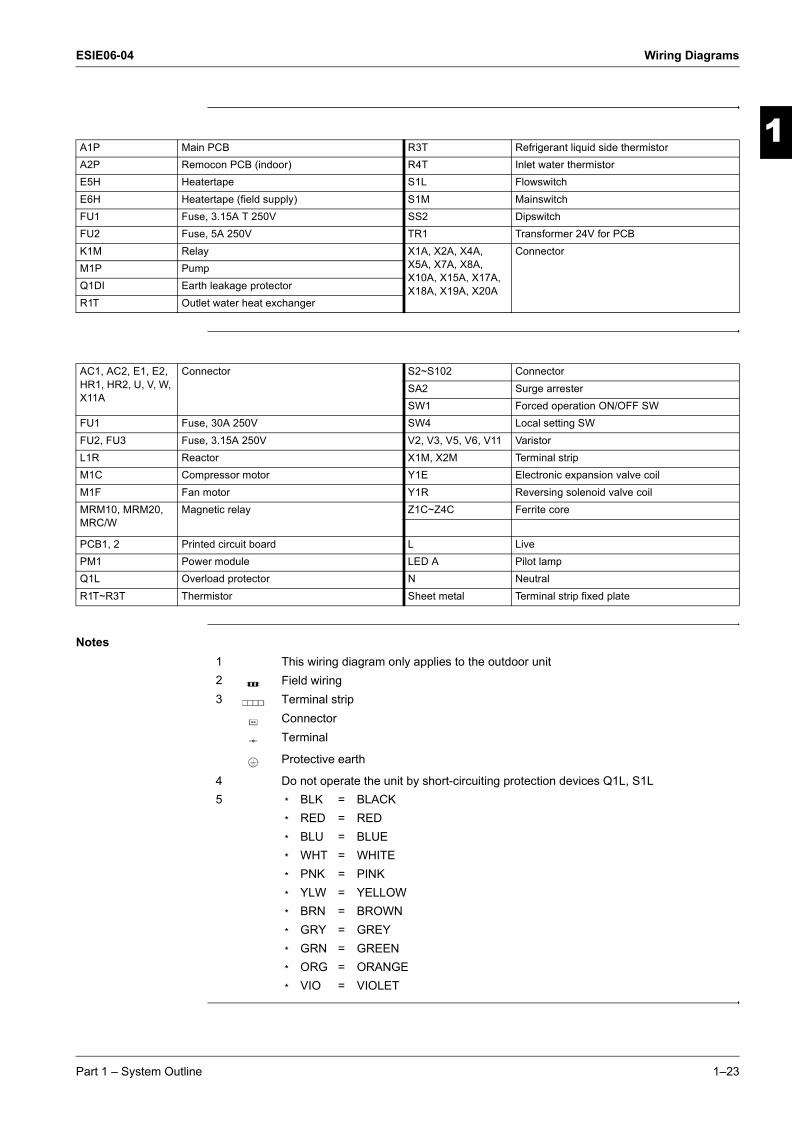
A1P Main PCB R3T Refrigerant liquid side thermistorA2P Remocon PCB (indoor) R4T Inlet water thermistorE5H Heatertape S1L FlowswitchE6H Heatertape (field supply) S1M MainswitchFU1 Fuse, 3.15A T 250V SS2 DipswitchFU2 Fuse, 5A 250V TR1 Transformer 24V for PCBK1M Relay X1A, X2A, X4A,
X5A, X7A, X8A, X10A, X15A, X17A, X18A, X19A, X20A
ConnectorM1P PumpQ1DI Earth leakage protectorR1T Outlet water heat exchanger
AC1, AC2, E1, E2, HR1, HR2, U, V, W, X11A
Connector S2~S102 ConnectorSA2 Surge arresterSW1 Forced operation ON/OFF SW
FU1 Fuse, 30A 250V SW4 Local setting SWFU2, FU3 Fuse, 3.15A 250V V2, V3, V5, V6, V11 VaristorL1R Reactor X1M, X2M Terminal stripM1C Compressor motor Y1E Electronic expansion valve coilM1F Fan motor Y1R Reversing solenoid valve coilMRM10, MRM20, MRC/W
Magnetic relay Z1C~Z4C Ferrite core
PCB1, 2 Printed circuit board L LivePM1 Power module LED A Pilot lampQ1L Overload protector N NeutralR1T~R3T Thermistor Sheet metal Terminal strip fixed plate
1 This wiring diagram only applies to the outdoor unit2 Field wiring3 Terminal strip
ConnectorTerminal
Protective earth
4 Do not operate the unit by short-circuiting protection devices Q1L, S1L5 m BLK = BLACK
m RED = REDm BLU = BLUEm WHT = WHITEm PNK = PINKm YLW = YELLOWm BRN = BROWNm GRY = GREYm GRN = GREENm ORG = ORANGEm VIO = VIOLET
Part 1 – System Outline 1–23

Wiring Diagrams ESIE06-04
3
11
4
5
ESIE06-04.book Page 24 Thursday, November 2, 2006 11:01 AM
1–24 Part 1 – System Outline
ESIE06-04 PCB Layout
1
ESIE06-04.book Page 25 Thursday, November 2, 2006 11:01 AM
Part 1
3
4
5
7 PCB Layout
7.1 What Is in This Chapter?
Introduction This chapter contains the following information:
m It describes which unit uses which PCB types
m It shows the PCB connectors.
Outdoor units This chapter contains the following PCB layouts:
PCB layout See page
7.2–EWA(Y)Q005~007A*V3 (Outdoor) 1–26
7.3–EWA(Y)Q005~007A*V3 (Hydro-kit) 1–30
Part 1 – System Outline 1–25
PCB Layout ESIE06-04
3
11
4
5
ESIE06-04.book Page 26 Thursday, November 2, 2006 11:01 AM
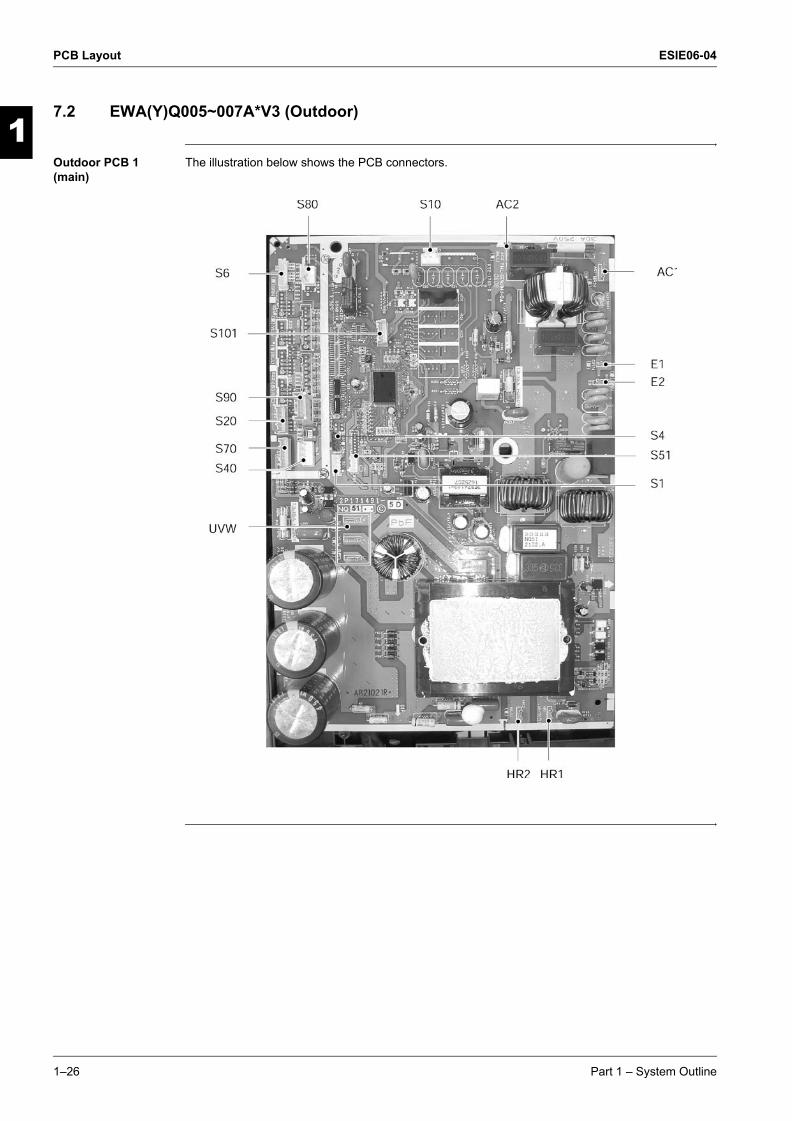
7.2 EWA(Y)Q005~007A*V3 (Outdoor)
Outdoor PCB 1 (main)
The illustration below shows the PCB connectors.
1–26 Part 1 – System Outline

ESIE06-04 PCB Layout
3
1
4
5
ESIE06-04.book Page 27 Thursday, November 2, 2006 11:01 AM
Connectors The table below describes the PCB connectors.
Connector Connected to Description
S1S4S6S10 X2M Terminal strip: CommunicationS20 Y1E Electronic expansion valveS40 Q1L Overload protectorS51 PCB2 (S52) Printed circuit boardS70 M1F Fan motorS80 Y1R 4-Way valveS90 R1T Thermistor (Discharge)
R2T Thermistor (Condensor)R3T Thermistor (Outdoor)
S101 PCB2 (S102) Printed circuit boardAC1 X1M Terminal strip: Power supplyAC2HR1 L1R Reactor coilHR2UVW M1C Inverter compressor
Part 1 – System Outline 1–27

PCB Layout ESIE06-04
3
11
4
5
ESIE06-04.book Page 28 Thursday, November 2, 2006 11:01 AM
Outdoor PCB 2 The illustration below shows the PCB connectors.
1–28 Part 1 – System Outline

ESIE06-04 PCB Layout
3
1
4
5
ESIE06-04.book Page 29 Thursday, November 2, 2006 11:01 AM
Connectors The table below describes the PCB connectors.
Connector Connected to Description
S2 Not applicableS52 PCB 1 (S51) Printed circuit boardS102 PCB 1 (S101) Printed circuit boardSW1 - Forced operation On/OffSW4 - Dip switch
Part 1 – System Outline 1–29

PCB Layout ESIE06-04
3
11
4
5
ESIE06-04.book Page 30 Thursday, November 2, 2006 11:01 AM
7.3 EWA(Y)Q005~007A*V3 (Hydro-kit)
Main PCB The illustration below shows the PCB connectors.
1–30 Part 1 – System Outline

ESIE06-04 PCB Layout
3
1
4
5
ESIE06-04.book Page 31 Thursday, November 2, 2006 11:01 AM
Connectors The table below describes the PCB connectors for the Hydro-kit:
Connector Connected to Terminal nr. Description
X1A TR1 - Transformer (220 V/24 V)X2A TR1 - Transformer (220 V/24 V)X3A Q1L 24-25 Not ApplicableX4A S1L - FlowswitchX5A R1T (A1P) - Outlet water heat exchanger thermistorX6A R2T - Not ApplicableX7A R3T - Refrigerant liquid side thermistorX8A R4T - Inlet water thermistorX9A R5T - Not ApplicableX10A - - VRV checker connectionX11A K1M - Not ApplicableX12A K2M - Not ApplicableX13A K3M - Not ApplicableX14A - - Not ApplicableX15A M1P - PumpX16A M3S 19-20 Not ApplicableX17A PCB (A3P) 13-15-17-23 Not ApplicableX18A PCB (A2P) - Remote controler PCBX19A ERYQ 9-10-11 Therminal nr. 9-11: internal wiring to outdoorX20A M2S 14-16-18 Not ApplicableX21A Q2L 21-22 Not Applicable
Part 1 – System Outline 1–31

PCB Layout ESIE06-04
3
11
4
5
ESIE06-04.book Page 32 Thursday, November 2, 2006 11:01 AM
1–32 Part 1 – System Outline

ESIE06-04
4
3
4
5
2
ESIE06-04.book Page 1 Thursday, November 2, 2006 11:01 AM
Part 2Functional Description
What is in this part? This part contains information on the functions used to control the system. Understanding these functions is vital when diagnosing a malfunction that is related to the functional control.
Overview This part contains the following chapters:
Chapter See page
1–General Functionality 2–3
2–Hydro-kit Functional Concept 2–7
3–Outdoor Unit Functional Concept 2–11
Part 2 – Functional Description 2–1

ESIE06-04
3
1
2
5
ESIE06-04.book Page 2 Thursday, November 2, 2006 11:01 AM
2–2 Part 2 – Functional Description

ESIE06-04 General Functionality
1
ESIE06-04.book Page 3 Thursday, November 2, 2006 11:01 AM
Part 2
3
4
5
2
1 General Functionality
1.1 What Is in This Chapter?
Introduction This chapter will explain all functions not related to the compressor frequency control, outdoor unit fan control and expansion valve control. These functions have been programmed to ensure the unit's reliability and lifetime, enable the operation in case of malfunction.
Overview This chapter contains the following topics:
Topic See page
1.2–Preheating Operation 2–4
1.3–Four Way Valve Switching 2–5
1.4–Freeze-up Protection Control 2–6
Part 2 – Functional Description 2–3
General Functionality ESIE06-04
3
1
2
4
5
ESIE06-04.book Page 4 Thursday, November 2, 2006 11:01 AM
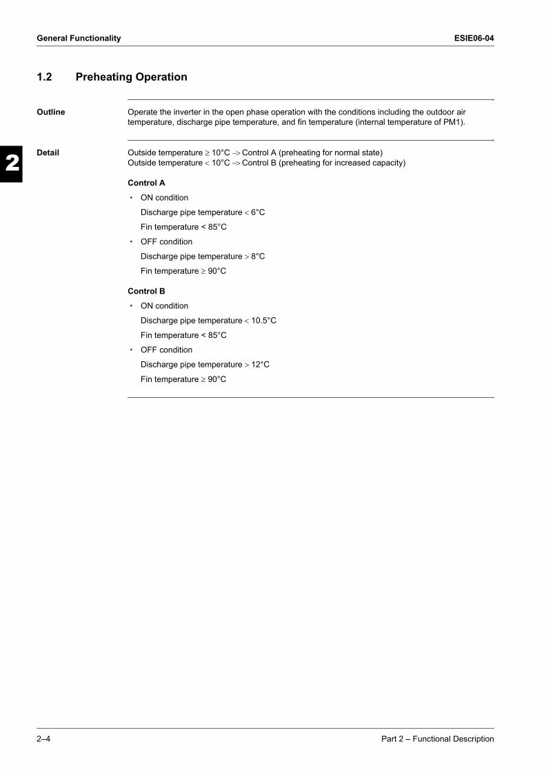
1.2 Preheating Operation
Outline Operate the inverter in the open phase operation with the conditions including the outdoor air temperature, discharge pipe temperature, and fin temperature (internal temperature of PM1).
Detail Outside temperature ≥ 10°C −> Control A (preheating for normal state)Outside temperature < 10°C −> Control B (preheating for increased capacity)
Control A
m ON condition
Discharge pipe temperature < 6°C
Fin temperature < 85°C
m OFF condition
Discharge pipe temperature > 8°C
Fin temperature ≥ 90°C
Control B
m ON condition
Discharge pipe temperature < 10.5°C
Fin temperature < 85°C
m OFF condition
Discharge pipe temperature > 12°C
Fin temperature ≥ 90°C
2–4 Part 2 – Functional Description
ESIE06-04 General Functionality
3
2
4
5
1
ESIE06-04.book Page 5 Thursday, November 2, 2006 11:01 AM
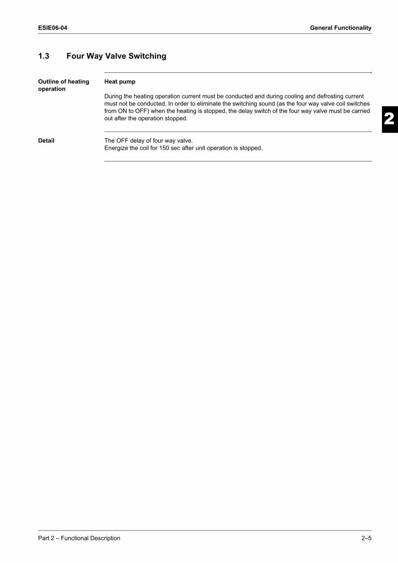
1.3 Four Way Valve Switching
Outline of heating operation
Heat pump
During the heating operation current must be conducted and during cooling and defrosting current must not be conducted. In order to eliminate the switching sound (as the four way valve coil switches from ON to OFF) when the heating is stopped, the delay switch of the four way valve must be carried out after the operation stopped.
Detail The OFF delay of four way valve.Energize the coil for 150 sec after unit operation is stopped.
Part 2 – Functional Description 2–5

General Functionality ESIE06-04
3
1
2
4
5
ESIE06-04.book Page 6 Thursday, November 2, 2006 11:01 AM
1.4 Freeze-up Protection Control
Outline During cooling operation, the signals being sent from the Hydro-kit allow the operating frequency limitation and then prevent freezing of the indoor heat exchanger. (The signal from the Hydro-kit must be divided into the zones as the followings.
Conditions for start controlling
Judge the controlling start with the indoor heat exchanger temperature after 2 sec from operation start.
Control in each zone
A
Heat exchangerthermistor temperature Return / Reset zone
Up zone
Keep zone
Drooping zone
Stop zone
B
C
D
E
2–6 Part 2 – Functional Description
ESIE06-04 Hydro-kit Functional Concept
1
ESIE06-04.book Page 7 Thursday, November 2, 2006 11:01 AM
Part 2
3
4
5
2
2 Hydro-kit Functional Concept
2.1 What Is in This Chapter?
Introduction This chapter will explain more details about the various functions that are programmed for the Hydro-kit.
Overview This chapter contains the following topics:
Topic See page
2.2–Defrost Control 2–8
2.3–Forced Operation Model 2–9
Part 2 – Functional Description 2–7

Hydro-kit Functional Concept ESIE06-04
3
1
2
4
5
ESIE06-04.book Page 8 Thursday, November 2, 2006 11:01 AM
2.2 Defrost Control
Outline Heat pump
Defrosting is carried out by the cooling cycle (reverse cycle). The defrosting time or outdoor heat exchanger temperature must be more than its fixed value when finishing.
Conditions for starting defrost
The starting conditions must be made with the outdoor air temperature and heat exchanger temperature. Under the conditions that the system is in heating operation, 6 minutes after the compressor is started and more than 44 minutes of accumulated time pass since the start of the operation or ending the defrosting.
Conditions for canceling defrost
The judgment must be made with heat exchanger temperature. (4°C~12°C).
Frequency
Compressor
Four way valve
Fan
Electronic expansionvalve opening
ON
OFF
ON
OFF
ON
OFF
0Hz
55Hz
2YC63 : 74Hz
5sec.
450pps450pps450ppsInitial opening
PI control
5sec.
50sec.60sec. 340 sec.
120sec.
2–8 Part 2 – Functional Description
ESIE06-04 Hydro-kit Functional Concept
3
2
4
5
1
ESIE06-04.book Page 9 Thursday, November 2, 2006 11:01 AM
2.3 Forced Operation Model
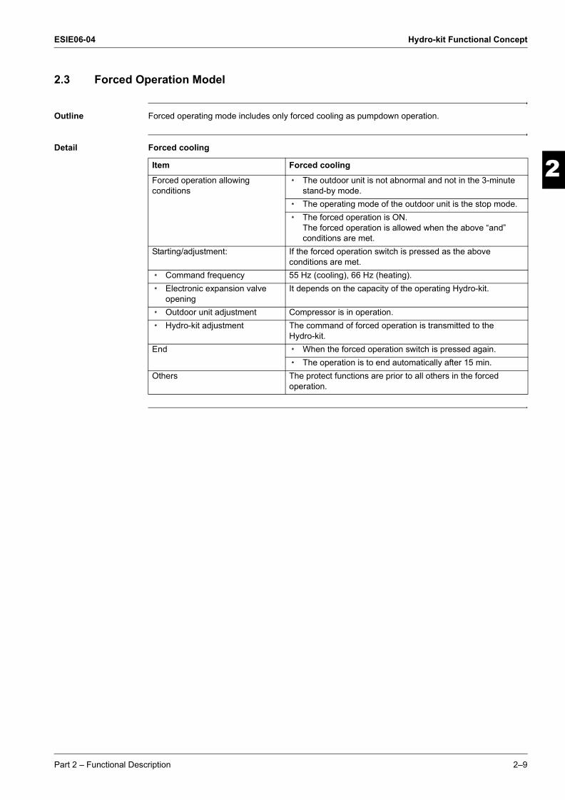
Outline Forced operating mode includes only forced cooling as pumpdown operation.
Detail Forced cooling
Item Forced cooling
Forced operation allowing conditions
m The outdoor unit is not abnormal and not in the 3-minute stand-by mode.
m The operating mode of the outdoor unit is the stop mode.m The forced operation is ON.
The forced operation is allowed when the above “and” conditions are met.
Starting/adjustment: If the forced operation switch is pressed as the above conditions are met.
m Command frequency 55 Hz (cooling), 66 Hz (heating).m Electronic expansion valve
openingIt depends on the capacity of the operating Hydro-kit.
m Outdoor unit adjustment Compressor is in operation.m Hydro-kit adjustment The command of forced operation is transmitted to the
Hydro-kit.End m When the forced operation switch is pressed again.
m The operation is to end automatically after 15 min.Others The protect functions are prior to all others in the forced
operation.
Part 2 – Functional Description 2–9
Hydro-kit Functional Concept ESIE06-04
3
1
2
4
5
ESIE06-04.book Page 10 Thursday, November 2, 2006 11:01 AM
2–10 Part 2 – Functional Description

ESIE06-04 Outdoor Unit Functional Concept
1
ESIE06-04.book Page 11 Thursday, November 2, 2006 11:01 AM
Part 2
3
2
4
5
3 Outdoor Unit Functional Concept
3.1 What Is in This Chapter?
Introduction This chapter will explain more details about the various functions that are programmed for the sky-air R410A inverter outdoor units.
Overview This chapter contains the following topics:
Topic See page
3.2–Frequency Principle 2–12
3.3–Frequency Control 2–14
3.4–Controls at Mode Changing / Start-up 2–16
3.5–Discharge Pipe Temperature Control 2–17
3.6–Input Current Control 2–18
3.7–Heating Peak-cut Control 2–19
3.8–Fan Control 2–20
3.9–Liquid Compression Protection Function 2 2–21
3.10–Low Hz High Pressure Limit 2–22
3.11–Electronic Expansion Valve Controll 2–23
3.12–Malfunctions 2–27
Part 2 – Functional Description 2–11

Outdoor Unit Functional Concept ESIE06-04
3
1
2
4
5
ESIE06-04.book Page 12 Thursday, November 2, 2006 11:01 AM
3.2 Frequency Principle
Main control parameters
The compressor is frequency-controlled during normal operation. The target frequency is set by the following 2 parameters coming from the operating Hydro-kit:
m The load condition of the operating Hydro-kit
m The difference between the water temperature and the set temperature
Additional control parameters
The target frequency is adapted by additional parameters in the following cases:
m Frequency restrictions
m Initial settings
m Forced cooling operation
Inverter principle To regulate the capacity, a frequency control is needed. The inverter makes it possible to vary the rotation speed of the compressor. The following table explains the conversion principle:
Drawing of inverter The following drawing shows a schematic view of the inverter principle:
Phase Description
1 The supplied AC power source is converted into the DC power source for the present.2 The DC power source is reconverted into the three phase AC power source with varia-
ble frequency.
m When the frequency increases, the rotation speed of the compressor increases resulting in an increased refrigerant circulation. This leads to a higher amount of the heat exchange per unit.
m When the frequency decreases, the rotation speed of the compressor decreases resulting in a decreased refrigerant circulation. This leads to a lower amount of the heat exchange per unit.
50 Hz
Refrigerant circulation rate (high)
Amount of heatexchanged (large)
Amount of heatexchanged (small)
AC
pow
er
freq=constant
DC
pow
er
Amount of heatexchanged (large)
Amount of heatexchanged (small)
high f
low f
freq=variable capacity=variable
Refrigerant circulation rate (low)
high speed
low speed
2–12 Part 2 – Functional Description

ESIE06-04 Outdoor Unit Functional Concept
3
2
4
5
1
ESIE06-04.book Page 13 Thursday, November 2, 2006 11:01 AM
Inverter features The inverter provides the following features:
m The regulating capacity can be changed according to the changes in the outside temperature and cooling/heating load.
m Quick heating and quick cooling
The compressor rotational speed is increased when starting the heating (or cooling). This enables a quick set temperature.
m Energy saving heating and cooling
Once the set temperature is reached, the energy saving operation enables to maintain the room temperature at low power.
Frequency limits The following table shows the functions that define the minimum and maximum frequency:
60 120 300
T˚C
Dischargetemperature
inverter
normal heat pump
Start seconds
Frequency limits Limited during the activation of following functions
Low m Four way valve operation compensation. Refer to page 2–16.High m Input current control. Refer to page 2–18.
m Compressor protection function. Refer to page 2–16.
m Heating peak-cut control. Refer to page 2–19.
Part 2 – Functional Description 2–13

Outdoor Unit Functional Concept ESIE06-04
3
1
2
4
5
ESIE06-04.book Page 14 Thursday, November 2, 2006 11:01 AM
3.3 Frequency Control
Outline Frequency will be determined according to the difference between water and set temperature.The function is explained as follows.
m How to determine frequency.
m Frequency command from a Hydro-kit (the difference between the water temperature and the temperature set by the remote controller).
m Frequency command from a Hydro-kit.
m Frequency initial setting.
m PI control.
How to determine frequency
The compressor’s frequency will finally be determined by taking the following steps.
For heat pump model
m Determine command frequency
Command frequency will be determined in the following order of priority.m Limiting frequency by drooping function
Input current, discharge pipes, low Hz high pressure limit, peak cutting, freeze prevention, fin thermistor temperature.
m Limiting defrost control timem Forced coolingm Indoor frequency command
m Determine upper limit frequency
Set a minimum value as an upper limit frequency among the frequency upper limits of the following functions:Compressor protection, input current, discharge pipes, Low Hz high pressure, peak cutting, freeze prevention, defrost.
m Determine lower limit frequency
Set a maximum value as an lower limit frequency among the frequency lower limits of the following functions: Four way valve operating compensation, pressure difference upkeep.
m Determine prohibited frequency
There is a certain prohibited frequency such as a power supply frequency.
Command frequency Limit frequency Skip control
Upper limit functionCompressor protection function
Lower limit functionFour-way valve operating compensation, etc.
Initial frequency PI control
Defrost control
Drooping functionInput current control, etc.
Upper limit frequencyFMAX
Lower limit frequency
Target frequency
Command frequency X repeats when frequency becomes lower
Frequency changes by PI control < repeats when frequency becomes lower
2–14 Part 2 – Functional Description

ESIE06-04 Outdoor Unit Functional Concept
3
2
4
5
1
ESIE06-04.book Page 15 Thursday, November 2, 2006 11:01 AM
Indoor frequency command (∆D signal)
The difference between the outlet water temperature and the temperature set by the remote controller will be taken as the “∆D signal” and is used for frequency command.
Frequency initial setting
When starting the compressor, or when conditions are varied due to the change of the room, the frequency must be initialized according to the total of a maximum ∆D value of the Hydro-kit and the Q value of the Hydro-kit.
Q value: Hydro-kit output determined from Hydro-kit.
PI Control (determine frequency up/down by ∆D signal)
m P control
Calculate ∆D value in each sampling time (20 seconds), and adjust the frequency according to its difference from the frequency previously calculated.
m I control
If the operating frequency is not change more than a certain fixed time, adjust the frequency up and down according to the ∆D value, obtaining the fixed ∆D value.When the ∆D value is small...lower the frequency.When the ∆D value is large...increase the frequency.
m Limit of frequency variation width
When the difference between input current and input current drooping value is less than 1.5 A, the frequency increase width must be limited.
m Frequency management when other controls are functioningm When frequency is drooping;
Frequency management is carried out only when the frequency droops.m For limiting lower limit
Frequency management is carried out only when the frequency rises.
m Upper and lower limit of frequency by PI control
The frequency upper and lower limits are set depending on Hydro-kit.When outdoor unit low noise or quiet commands come from Hydro-kit, the upper limit frequency must be lowered than the usual setting.
Part 2 – Functional Description 2–15

Outdoor Unit Functional Concept ESIE06-04
3
1
2
4
5
ESIE06-04.book Page 16 Thursday, November 2, 2006 11:01 AM
3.4 Controls at Mode Changing / Start-up
Four way valve operation compensation
Heat pump
At the beginning of the operation as the four way valve is switched, acquire the differential pressure required for activating the four way valve by having output the operating frequency, which is more than a certain fixed frequency, for a certain fixed time.
Starting conditions
m The MRC/W turns ON when the compressor starts for heating after the MRC/W has been OFF with compressor halted.
m The MRC/W turns OFF when the compressor starts for cooling after the MRC/W has been ON with compressor running.
m The compressor starts for the first time after reset.
m The compressor starts after suspension caused by the trouble of cooling/heating changeover. Set the lower limit frequency to 48 Hz for 70 seconds with any conditions 1 through 4 above.
3 minutes stand-by Prohibit to turn ON the compressor for 3 minutes after turning it off. Except when defrosting.
Compressor protection function
When turning the compressor from OFF to ON, the upper limit of frequency must be set as follows. The function must not be used when defrosting.
FCG 3 85FCG 2 70FCG 1 55
Frequency
FCG3FCG2FCG1
TimeTCG470 secTCG200 secTCG120 sec
2–16 Part 2 – Functional Description

ESIE06-04 Outdoor Unit Functional Concept
3
2
4
5
1
ESIE06-04.book Page 17 Thursday, November 2, 2006 11:01 AM
3.5 Discharge Pipe Temperature Control
Outline The discharge pipe temperature is used as the compressor's internal temperature. If the discharge pipe temperature rises above a certain level, the operating frequency upper limit is set to keep this temperature from going up further.
Divide the zone
Management within the zones
50/60/71 classA 120B 111C 109D 107E 107
A˚C
B˚C
C˚C
D˚C
E˚CReset zone
Keep zone
Drooping zone
Stop zone
Discharge pipe temperature
Zone Control contents
Stop zone When the temperature reaches the stop zone, stop the compressor and cor-rect abnormality.
Drooping zone Start the timer, and the frequency will be drooping.Keep zone Keep the upper limit of frequency.Reset zone Cancel the upper limit of frequency.
Part 2 – Functional Description 2–17

Outdoor Unit Functional Concept ESIE06-04
3
1
2
4
5
ESIE06-04.book Page 18 Thursday, November 2, 2006 11:01 AM
3.6 Input Current Control
Outline The microcomputer calculates the input current during the compressor is running, and set the frequency upper limit from such input current.
This control is the upper limit control function of the frequency which takes priority of the lower limit of four way valve activating compensation.
Graph
Frequency control in each zone
m Drooping zonem The maximum limit of the compressor frequency in this control is defined as operation frequency
- 2Hz.m After this, the output frequency is pulled down by 2Hz every second until it reaches the steady
zone.
m Keep zonem The present maximum frequency goes on.
m Reset zonem Limit of the frequency is cancelled.
m Stop zonem After 2.5 s in this zone, the compressor is stopped.
Limitation of current drooping and stop value according to the outdoor air temperature
m In case the operation mode is cooling
The current droops when outdoor air temperature becomes higher than a certain level.
m In case the operation mode is heating
The current droops when outdoor air temperature becomes higher than a certain level.
Compressor Stop
Drooping Zone
Stop Zone
Keep Zone
Reset Zone
I4
I3
I3 –Iα
Cooling Heating
50 class 60 class 71 class 50 class 60 class 71 classI4 (A) 20 20I3 (A) Normal mode - - 15.75 - - 17.5I3-Iα (A) Normal mode - - 14.75 - - 16.5
2–18 Part 2 – Functional Description

ESIE06-04 Outdoor Unit Functional Concept
3
2
4
5
1
ESIE06-04.book Page 19 Thursday, November 2, 2006 11:01 AM
3.7 Heating Peak-cut Control
Outline Heat pump only
During heating operation, the signals being sent from the Hydro-kit allow the operating frequency limitation and prevent abnormal high pressure (the signal from the Hydro-kit must be divided as follows).
Conditions for start controlling
Judge the controlling start with the indoor heat exchanger temperature after 5 sec from operation start.
Control in each zone
The heat exchange intermediate temperature of Hydro-kit controls the following.
Heat exchangerthermistor temperature
Return / Reset zone
Up zone
Keep zone
Drooping zone
Stop zone
Part 2 – Functional Description 2–19

Outdoor Unit Functional Concept ESIE06-04
3
1
2
4
5
ESIE06-04.book Page 20 Thursday, November 2, 2006 11:01 AM
3.8 Fan Control
Outline Fan control is carried out according to the following priority:
m Fan ON control for electric component cooling fan
m Fan control when defrosting
m Fan OFF delay when stopped
m Fan control for maintaining pressure difference
m Fan control when the compressor starts for heating
m Fan control in forced operation
m Fan control in powerful mode
m Fan control in low noise operation
m Fan control in silent mode
Fan OFF control when stopped
Fan OFF delay for 60 seconds must be made when the compressor is stopped.
2–20 Part 2 – Functional Description
ESIE06-04 Outdoor Unit Functional Concept
3
2
4
5
1
ESIE06-04.book Page 21 Thursday, November 2, 2006 11:01 AM
3.9 Liquid Compression Protection Function 2
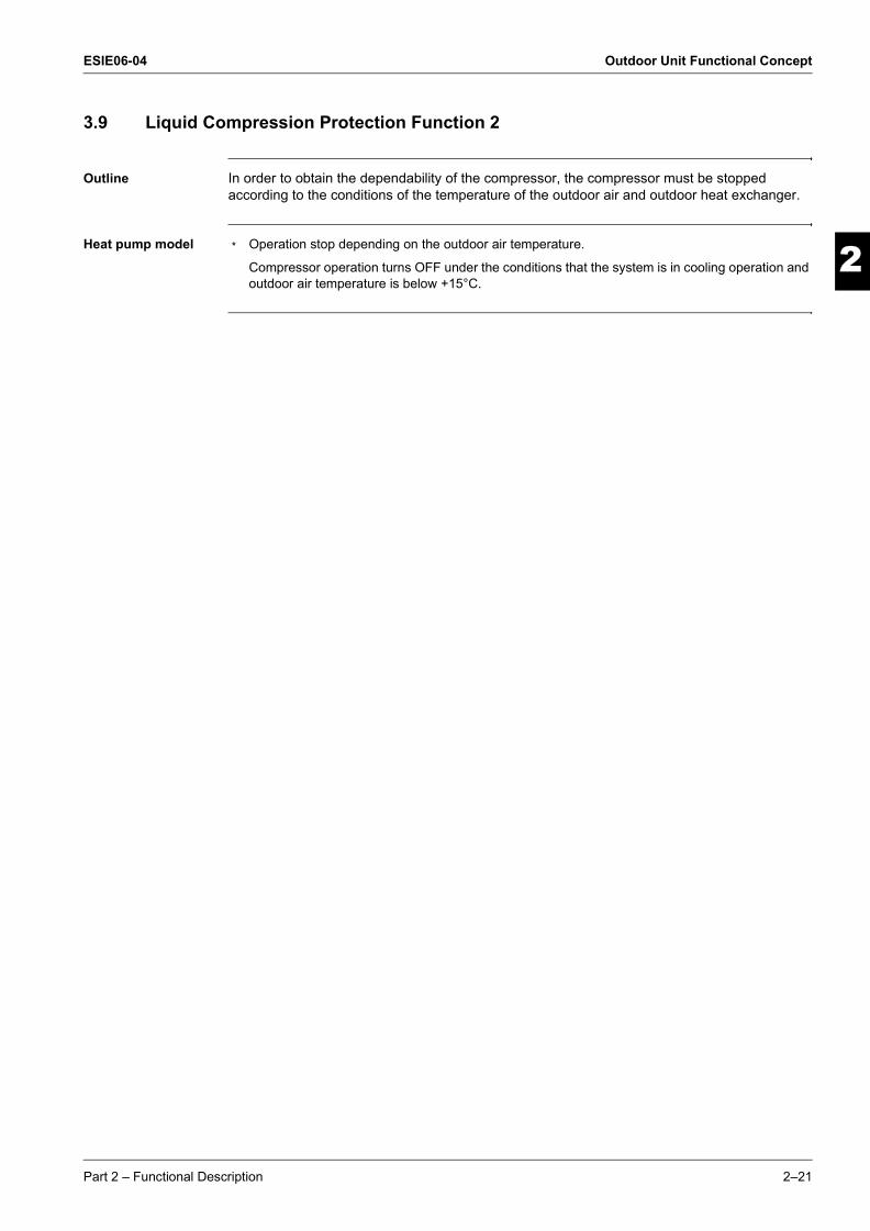
Outline In order to obtain the dependability of the compressor, the compressor must be stopped according to the conditions of the temperature of the outdoor air and outdoor heat exchanger.
Heat pump model m Operation stop depending on the outdoor air temperature.
Compressor operation turns OFF under the conditions that the system is in cooling operation and outdoor air temperature is below +15°C.
Part 2 – Functional Description 2–21

Outdoor Unit Functional Concept ESIE06-04
3
1
2
4
5
ESIE06-04.book Page 22 Thursday, November 2, 2006 11:01 AM
3.10 Low Hz High Pressure Limit
Outline Heat Pump Only
Set the upper limit of high pressure in a low Hz zone. Set the upper limit of the indoor heat exchanger temperature by its operating frequency of Hz. Separate into three zones, reset zone, unchanged zone and drooping zone and the frequency control must be carried out in such zones.
Separate into zones
Note Drooping: The system stops after staying in the drooping zone for 2 minutes.
Highest heatexchangertemperatureamong theoperating rooms
Reset zone
60˚C
59˚C
56˚CUnchangedzone
Drooping zone
2–22 Part 2 – Functional Description

ESIE06-04 Outdoor Unit Functional Concept
3
2
4
5
1
ESIE06-04.book Page 23 Thursday, November 2, 2006 11:01 AM
3.11 Electronic Expansion Valve Controll
Overview This chapter contains the following topics:
Outline The following items are included in the electronic expansion valve control.
m Electronic expansion valve is fully closedm Electronic expansion valve is fully closed when turning on the power.m Pressure equalizing control
m Open Controlm Electronic expansion valve control when starting operationm Control when frequency changedm Control for defrostingm Control when a discharge pipe temperature is abnormally highm Control when the discharge pipe thermistor is disconnected
m Feedback Controlm Discharge pipe temperature control
Topic See page
3.11.1–Fully Closing with Power ON 2–24
3.11.2–Pressure Equalization Control 2–25
3.11.3–Opening Limit 2–25
3.11.4–Starting Operation Control 2–25
3.11.5–High Temperature of the Discharge Pipe 2–25
3.11.6–Disconnection of the Discharge Pipe Thermistor 2–25
3.11.7–Control when frequency is changed 2–26
3.11.8–Target Discharge Pipe Temperature Control 2–26
Part 2 – Functional Description 2–23

Outdoor Unit Functional Concept ESIE06-04
3
1
2
4
5
ESIE06-04.book Page 24 Thursday, November 2, 2006 11:01 AM
Detail The followings are the examples of control which function in each mode by the electronic expansion valve control.
3.11.1 Fully Closing with Power ON
Initialize the electronic expansion valve when turning on the power, set the opening position and develop pressure equalizing.
Fully closed when power is turned ON
Open control when starting
(Control of target discharge pipe temperature)
Pressure equalizing control
Open control when starting
(Control of target discharge pipe temperature)
(Defrost control FD=1)
Pressure equalizing control
Open control when starting
Pressure equalizing control
When power is turned ON
Cooling operation
Stop
Heating operation
Stop
Heating operation
Control of discharge pipe thermistor disconnection
Stop
×
×
×
×
×
×
×
×
×
×
×
×
×
×
×
Con
trol
whe
n fr
eque
ncy
chan
ged
Con
trol
for
abno
rmal
ly h
igh
disc
harg
e pi
pe
tem
pera
tureOperation pattern
(only for heat pump model)
: function × : not function
(only for heat pump model)
Continue
2–24 Part 2 – Functional Description
ESIE06-04 Outdoor Unit Functional Concept
3
2
4
5
1
ESIE06-04.book Page 25 Thursday, November 2, 2006 11:01 AM
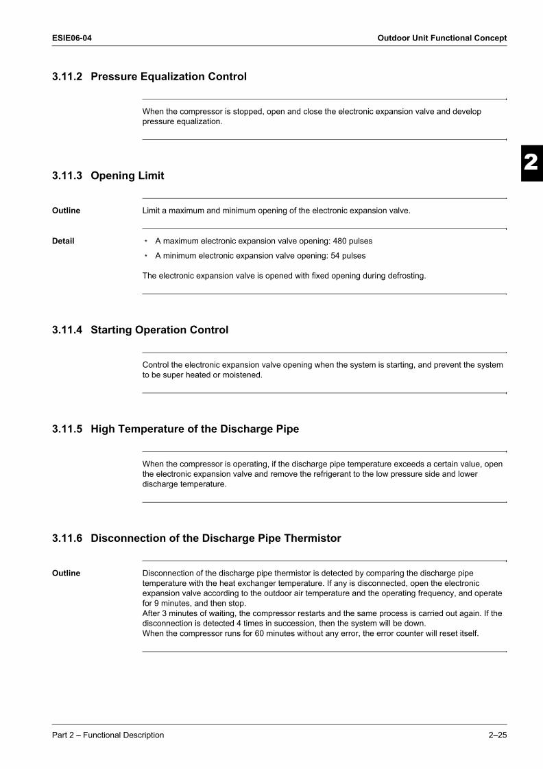
3.11.2 Pressure Equalization Control
When the compressor is stopped, open and close the electronic expansion valve and develop pressure equalization.
3.11.3 Opening Limit
Outline Limit a maximum and minimum opening of the electronic expansion valve.
Detail m A maximum electronic expansion valve opening: 480 pulses
m A minimum electronic expansion valve opening: 54 pulses
The electronic expansion valve is opened with fixed opening during defrosting.
3.11.4 Starting Operation Control
Control the electronic expansion valve opening when the system is starting, and prevent the system to be super heated or moistened.
3.11.5 High Temperature of the Discharge Pipe
When the compressor is operating, if the discharge pipe temperature exceeds a certain value, open the electronic expansion valve and remove the refrigerant to the low pressure side and lower discharge temperature.
3.11.6 Disconnection of the Discharge Pipe Thermistor
Outline Disconnection of the discharge pipe thermistor is detected by comparing the discharge pipe temperature with the heat exchanger temperature. If any is disconnected, open the electronic expansion valve according to the outdoor air temperature and the operating frequency, and operate for 9 minutes, and then stop.After 3 minutes of waiting, the compressor restarts and the same process is carried out again. If the disconnection is detected 4 times in succession, then the system will be down.When the compressor runs for 60 minutes without any error, the error counter will reset itself.
Part 2 – Functional Description 2–25

Outdoor Unit Functional Concept ESIE06-04
3
1
2
4
5
ESIE06-04.book Page 26 Thursday, November 2, 2006 11:01 AM
Detect disconnection
When the 630-seconds timer for open control is over, the following adjustment must be made.
m When the operation mode is cooling
When the following condition is fulfilled, the discharge pipe thermistor disconnection is ascertained.Discharge pipe temperature +6°C < outdoor heat exchanger temperature.
m When the operation mode is heating
When the following condition is fulfilled, the discharge pipe thermistor disconnection is ascertained.Discharge pipe temperature +6°C < indoor heat exchanger temperature.
3.11.7 Control when frequency is changed
When the target discharge pipe temperature control is active, if the target frequency is changed for a specified value in a certain time period, cancel the target discharge pipe temperature control and change the target opening of the electronic expansion valve according to the shift.
3.11.8 Target Discharge Pipe Temperature Control
Obtain the target discharge pipe temperature from the indoor and outdoor heat exchanger temperature, and adjust the electronic expansion valve opening so that the actual discharge pipe temperature become close to that temperature. (Indirect SH control using the discharge pipe temperature).
Determine a correction value of the electronic expansion valve compensation and drive it according to the deflection of the target discharge temperature and actual discharge temperature, and the discharge temperature variation by the 20 sec.
Set the target discharge pipetemperature as to become an aimingSH.Regard that the inclination cannot bechanged due to the operatingcondition.
SC
SH
2–26 Part 2 – Functional Description

ESIE06-04 Outdoor Unit Functional Concept
3
2
4
5
1
ESIE06-04.book Page 27 Thursday, November 2, 2006 11:01 AM
3.12 Malfunctions
Overview This chapter contains the following topics:
3.12.1 Sensor Malfunction Detection
General Sensor malfunction may occur either in the thermistor or current transformer (CT) system.
Relating to thermistor malfunction
m Outdoor heat exchanger thermistor
m Discharge pipe thermistor
m Fin thermistor
m Outside air thermistor
Relating to CT malfunction
When the output frequency is more than 55 Hz and the input current is less than 0.5A, carry out abnormal adjustment.
3.12.2 Detection of Overload and Over Current
Outline In order to protect the inverter, detect an excessive output current, and for protecting compressor, monitor the OL operation.
Detail If the OL (compressor head) temperature exceeds 120~130°C (depending on the model), the compressor gets interrupted.
If the inverter current exceeds 30 A, the compressor gets interrupted too.
Topic See page
3.12.1–Sensor Malfunction Detection 2–27
3.12.2–Detection of Overload and Over Current 2–27
3.12.3–Insufficient Gas Control 2–28
Part 2 – Functional Description 2–27

Outdoor Unit Functional Concept ESIE06-04
3
1
2
4
5
ESIE06-04.book Page 28 Thursday, November 2, 2006 11:01 AM
3.12.3 Insufficient Gas Control
Outline If a power consumption is below the specified value in which the frequency is higher than the specified frequency, it must be regarded as gas insufficient.
In addition to such conventional function, if the discharge temperature is higher than the target discharge pipe temperature, and the electronic expansion valve is fully open (450 pulses) more than the specified time, it is considered as an insufficient gas.
With the conventional function, a power consumption is weak comparing with that in the normal operation when gas is insufficient, and gas insufficiency is detected by checking a power consumption.
When operating with insufficient gas, although the rise of discharge pipe temperature is great and the electronic expansion valve is open, it is presumed as an insufficient gas if the discharge pipe temperature is higher than the target discharge pipe temperature.
Judgment by input current
When an output frequency is exceeds 40 Hz and the input current is less than specified value, the adjustment is made for insufficient gas.
Judgment by discharge pipe temperature
When discharge pipe temperature is 20~45°C (depending on the model or mode) higher than target value and the electronic expansion value opening is 480 pulse (max.), the adjustment is made for insufficient gas.
FrequencyP
ower
con
sum
ptio
n
Insufficient gas zone
55 Hz
Gas insufficientzone
2–28 Part 2 – Functional Description
ESIE06-04
4
3
4
5
3
ESIE06-04.book Page 1 Thursday, November 2, 2006 11:01 AM
Part 3Troubleshooting
What is in this part? This part contains the following chapters:
Chapter See page
1–Troubleshooting 3–3
2–Error Codes: Hydro-kit 3–7
3–Error Codes: Outdoor Units 3–11
4–Error Codes: System Malfunctions 3–41
5–Additional Checks for Troubleshooting 3–49
Part 3 – Troubleshooting 3–1

ESIE06-04
3
1
3
5
ESIE06-04.book Page 2 Thursday, November 2, 2006 11:01 AM
3–2 Part 3 – Troubleshooting

ESIE06-04 Troubleshooting
1
ESIE06-04.book Page 3 Thursday, November 2, 2006 11:01 AM
Part 3
33
4
5
1 Troubleshooting
1.1 What Is in This Chapter?
Introduction When a problem occurs, you have to check all possible malfunctions. This chapter gives a general idea of where to look for malfunctions.
Not all repair procedures are described. Some procedures are considered common practice.
Overview This chapter contains the following topics:
Topic See page
1.2–Procedure of Self-Diagnosis by Remote Controller 3–4
1.3–Fault-diagnosis by Remote Controller 3–5
1.4–Overview of Error Codes 3–6
Part 3 – Troubleshooting 3–3

Troubleshooting ESIE06-04
3
1
3
4
5
ESIE06-04.book Page 4 Thursday, November 2, 2006 11:01 AM
1.2 Procedure of Self-Diagnosis by Remote Controller
The inspection/test button
The following modes can be selected by using the [Inspection/Test Operation] button on the remote control.
Remark Above information is general. Not all settings are applicable for Mini-chiller.
System settings can be made.m Auto restartm Backup heater operationm Others
Service data can be obtained.m Malfunciton code historym Temperature data of various sections
Depress Inspection/Test Operation button for more than 4 seconds.
Following codes can be checked.m Malfunction codesm Indoor model codem Outdoor model code
Press Inspection/Test Operation button once.
Press Inspection/Test Operation button once.
Press Inspection/Test Operation button once.Or after 30 minutes.
Depress Inspection/Test Operation button for more than 4 seconds.
Press Inspection/Test Operation button once.
After 10 seconds
Thermostat is forcibly turned on.
Local setting mode
Service mode
Normal mode
Inspection mode
Test operation
mode
3–4 Part 3 – Troubleshooting
ESIE06-04 Troubleshooting
33
4
5
1
ESIE06-04.book Page 5 Thursday, November 2, 2006 11:01 AM
1.3 Fault-diagnosis by Remote Controller
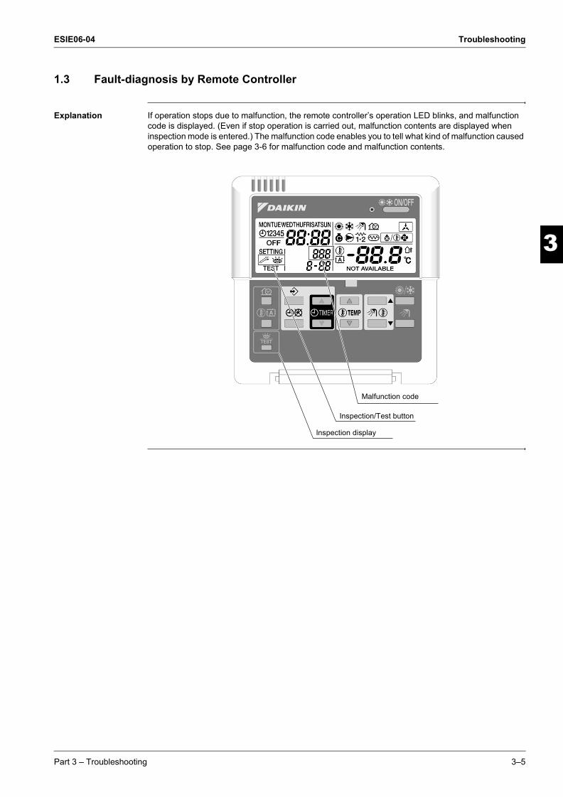
Explanation If operation stops due to malfunction, the remote controller’s operation LED blinks, and malfunction code is displayed. (Even if stop operation is carried out, malfunction contents are displayed when inspection mode is entered.) The malfunction code enables you to tell what kind of malfunction caused operation to stop. See page 3-6 for malfunction code and malfunction contents.
Inspection display
Inspection/Test button
Malfunction code
Part 3 – Troubleshooting 3–5

Troubleshooting ESIE06-04
3
1
3
4
5
ESIE06-04.book Page 6 Thursday, November 2, 2006 11:01 AM
1.4 Overview of Error Codes
Malfunction code Malfunction contents See page
Hyd
ro-k
it
80 Inlet water temperature thermistor abnormality 3–1081 Outlet water temperature thermistor abnormality 3–1089 Water heat exchanger freez-up abnormality ??7H Flow abnormality ??8H Outlet water temperature too high ??A1 Hydro-kit PCB abnormality 3–8A5 Freez-up protection or High pressure control 3–9C0 Flow switch abnormality ??C4 Heat exchanger thermistor abnormality 3–10
Out
door
Uni
t
E1 Outdoor unit PCB abnormality 3–12E5 OL Activation (compressor overload) 3–13E6 Compressor lock 3–15E7 DC fan lock 3–16E8 Input over current 3–17EA Heating / Cooling switching failure 3–19F3 Discharge pipe temperature control 3–21F6 Too high condensing pressure 3–23H0 Sensor abnormailty 3–25H6 Compressor start up failure 3–27H8 CT or related abnormailty 3–29H9 Outdoor temperature thermistor or related abnormality 3–31J3 Discharge pipe thermistor failure 3–31J6 Heat exchanger thermistor or related abnormality 3–31P4 Radiation fin thermistor or related abnormality 3–31L3 Switch box temperature rize 3–33L4 Radiation fin (power transistor) temperature rize 3–35L5 Output over current (inverter PCB) 3–37
Syst
em
mal
func
tions
U0 Refrigerant failure 3–42U2 Low-voltage or over-voltage detection 3–44U4 Signal transmission error (indoor outdoor unit) 3–45U7 Signal transmission error (indoor outdoor unit) 3–47UA Combination error (indoor outdoor unit) or spare parts PCB ??
3–6 Part 3 – Troubleshooting

ESIE06-04 Error Codes: Hydro-kit
1
ESIE06-04.book Page 7 Thursday, November 2, 2006 11:01 AM
Part 3
3
4
5
3
2 Error Codes: Hydro-kit
2.1 What Is in This Chapter?
Introduction In the first stage of the troubleshooting sequence, it is important to correctly interpret the error code on the remote controller display. The error code helps you to find the cause of the problem.
Shutdown For some errors, the system only shuts down when the error occurs several times. This means that you have to wait until the system shuts down to be able to see the flashing LED on the front panel and the error code on the remote controller.
Overview This chapter contains the following topics:
Topic See page
2.2–“A1” Hydro-kit PCB Abnormality 3–8
2.3–“A5” Freeze-up Protection Control or High Pressure Control 3–9
2.4–“C4, 81, 80” Thermistor or Related Abnormality (Hydro-kit) 3–10
Part 3 – Troubleshooting 3–7

Error Codes: Hydro-kit ESIE06-04
3
1
3
4
5
ESIE06-04.book Page 8 Thursday, November 2, 2006 11:01 AM
2.2 “A1” Hydro-kit PCB Abnormality
Error code A1
Method of malfunction detection
Evaluation of zero-cross detection of power supply by Hydro-kit.
Malfunction decision conditions
When there is no zero-cross detection in approximately 10 continuous seconds.
Supposed causes m Faulty Hydro-kit PCB
m Faulty connector connection
Troubleshooting
Caution Be sure to turn off power switch before connect or disconnect connector, or parts damage may be occurred.
Connector connection check(note).
NOIs it normal?
YES
Correct connections.
Replace PCBs.
3–8 Part 3 – Troubleshooting

ESIE06-04 Error Codes: Hydro-kit
4
5
1
3
ESIE06-04.book Page 9 Thursday, November 2, 2006 11:01 AM
2.3 “A5” Freeze-up Protection Control or High Pressure Control
Error code A5
Method of malfunction detection
m High pressure control (heat pump model only)
During heating operations, the temperature detected by the Hydro-kit heat exchanger thermistor is used for the high pressure control (stop, outdoor fan stop, etc.)
m The freeze-up protection control (operation halt) is activated during cooling operation according to the temperature detected by the Hydro-kit heat exchanger thermistor.
Malfunction decision conditions
m High pressure control
During heating operations, the temperature detected by the Hydro-kit heat exchanger thermistor is above 65°C
m Freeze-up protection
When the Hydro-kit heat exchanger temperature is below 0°C during cooling operation.
Supposed causes m Detection error due to faulty Hydro-kit heat exchanger thermistor.
m Detection error due to faulty Hydro-kit PCB.
Troubleshooting
See also "Check No.06" on page 3-53.
Caution Be sure to turn off power switch before connect or disconnect connector, or parts damage may be occurred.
Check No. 06Hydro-box heat exchanger
thermistor check
YESDoes it
conform to the thermistor characteristic
chart?
NO
Replace the hydro-box PCB.
Replace the thermistor (replace the hydro-box PCB).
Part 3 – Troubleshooting 3–9

Error Codes: Hydro-kit ESIE06-04
3
1
3
4
5
ESIE06-04.book Page 10 Thursday, November 2, 2006 11:01 AM
2.4 “C4, 81, 80” Thermistor or Related Abnormality (Hydro-kit)
Error code C4, 81, 80
Method of malfunction detection
The temperatures detected by the thermistors are used to determine thermistor errors.
Malfunction decision conditions
When the thermistor input is more than 4.96 V or less than 0.04 V during compressor operation*. * (reference)
When above about 212°C (less than 120 ohms) or below about –50°C (more than 1,860 kohms).
Note: The values vary slightly in some models.
Supposed causes m Faulty connector connection
m Faulty thermistor
m Faulty PCB
Troubleshooting
C4: Hydro-kit heat exchanger thermistor81: Outlet water temperature thermistor80: Inlet water temperature thermistor
See also "Check No.06" on page 3-53.
Correct the connection.
Replace the thermistor.(Replace the hydro-box PCB.)
Replace the hydro-box PCB.
YES
NO
YES
NO
Check No. 06Thermistor resistance check
Check the connector connection.
Is it normal?
Is it normal?
3–10 Part 3 – Troubleshooting

ESIE06-04 Error Codes: Outdoor Units
1
ESIE06-04.book Page 11 Thursday, November 2, 2006 11:01 AM
Part 3
33
4
5
3 Error Codes: Outdoor Units
3.1 What Is in This Chapter?
Introduction In the first stage of the troubleshooting sequence, it is important to correctly interpret the error code on the remote controller display. The error code helps you to find the cause of the problem.
Overview This chapter contains the following topics:
Topic See page
3.2–“E1” Outdoor Unit PCB Abnormality 3–12
3.3–“E5” OL Activation (Compressor Overload) 3–13
3.4–“E6” Compressor Lock 3–15
3.5–“E7” DC Fan Lock 3–16
3.6–“E8” Input Over Current Detection 3–17
3.7–“EA” Four Way Valve Abnormality 3–19
3.8–“F3” Discharge Pipe Temperature Control 3–21
3.9–“F6” High Pressure Control in Cooling 3–23
3.10–“H0” Compressor Sensor System Abnormality 3–25
3.11–“H6” Compressor Startup Failure 3–27
3.12–“H8” CT or Related Abnormality 3–29
3.13–“P4, J3, J6, H9” Thermistor or Related Abnormality (Outdoor Unit) 3–31
3.14–“L3” Switch Box Temperature Rise 3–33
3.15–“L4” Radiation Fin Temperature Rise 3–35
3.16–“L5” Output Over Current Detection 3–37
Part 3 – Troubleshooting 3–11

Error Codes: Outdoor Units ESIE06-04
3
1
3
4
5
ESIE06-04.book Page 12 Thursday, November 2, 2006 11:01 AM
3.2 “E1” Outdoor Unit PCB Abnormality
Error code E1
Method of malfunction detection
m Detect within the programme of the microcomputer that the programme is in normal running order.
Malfunction decision conditions
m When the programme of the microcomputer is in abnormal running order.
Supposed causes m Out of control of microcomputer caused by external factors
m Noise
m Momentary fall of voltage
m Momentary power loss
m Defective outdoor unit PCB
Troubleshooting
Caution Be sure to turn off power switch before connect or disconnect connector, or parts damage may be occurred.
Replace the outdoor unit PCB.
Carry out grounding work.
The cause can be external factors other than malfunction.Investigate the cause of noise.
Power on again
YES
NO
Error again?
Check to see that the machine is grounded.
NO
YES
Grounded?
3–12 Part 3 – Troubleshooting
ESIE06-04 Error Codes: Outdoor Units
33
4
5
1
ESIE06-04.book Page 13 Thursday, November 2, 2006 11:01 AM
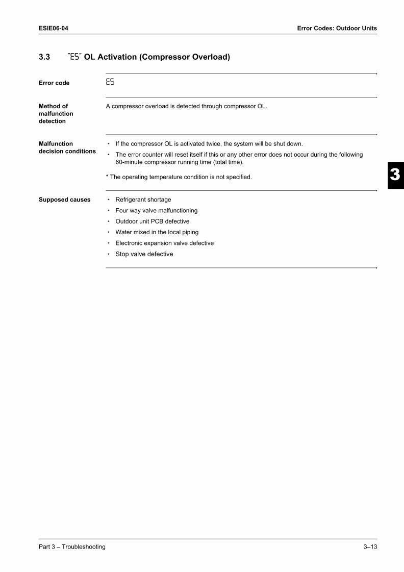
3.3 “E5” OL Activation (Compressor Overload)
Error code E5
Method of malfunction detection
A compressor overload is detected through compressor OL.
Malfunction decision conditions
m If the compressor OL is activated twice, the system will be shut down.
m The error counter will reset itself if this or any other error does not occur during the following 60-minute compressor running time (total time).
* The operating temperature condition is not specified.
Supposed causes m Refrigerant shortage
m Four way valve malfunctioning
m Outdoor unit PCB defective
m Water mixed in the local piping
m Electronic expansion valve defective
m Stop valve defective
Part 3 – Troubleshooting 3–13
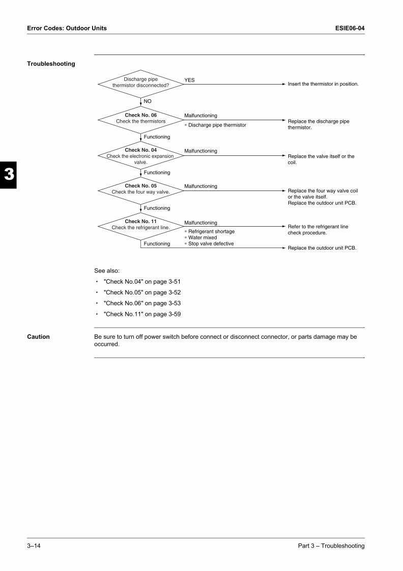
Error Codes: Outdoor Units ESIE06-04
3
1
3
4
5
ESIE06-04.book Page 14 Thursday, November 2, 2006 11:01 AM
Troubleshooting
See also:
m "Check No.04" on page 3-51
m "Check No.05" on page 3-52
m "Check No.06" on page 3-53
m "Check No.11" on page 3-59
Caution Be sure to turn off power switch before connect or disconnect connector, or parts damage may be occurred.
Insert the thermistor in position.
Replace the discharge pipe thermistor.
Replace the valve itself or the coil.
Replace the four way valve coil or the valve itself.Replace the outdoor unit PCB.
Refer to the refrigerant line check procedure.
Replace the outdoor unit PCB.
YES
Malfunctioning
∗ Discharge pipe thermistor
NO
Functioning
Functioning
Malfunctioning
∗ Refrigerant shortage∗ Water mixed∗ Stop valve defective
Discharge pipe thermistor disconnected?
Check No. 06Check the thermistors
Malfunctioning
Functioning
Check No. 04Check the electronic expansion
valve.
Malfunctioning
Functioning
Check No. 05Check the four way valve.
Check No. 11Check the refrigerant line.
3–14 Part 3 – Troubleshooting

ESIE06-04 Error Codes: Outdoor Units
33
4
5
1
ESIE06-04.book Page 15 Thursday, November 2, 2006 11:01 AM
3.4 “E6” Compressor Lock
Error code E6
Method of malfunction detection
A compressor lock is detected by checking the compressor running condition through the position detection circuit.
Malfunction decision conditions
m Judging from current waveform generated when high-frequency voltage is applied to the compressor.
m The system will be shut down if the error occurs 16 times.
m Clearing condition: Continuous run for about 5 minutes (normal)
Supposed causes m Compressor locked
Troubleshooting
Caution Be sure to turn off power switch before connect or disconnect connector, or parts damage may be occurred.
∗ Inverter checker Part No.: 1225477
Replace the compressor.
Replace the compressor.
Correct the power supply or replace the PM1. (Replace the outdoor unit PCB.)
Check the electronic expansion valve. Replace it as required.
NO
YES
YES
NO
NO
Normal?
System shut down after errors repeated
several times?
Turn off the power. Disconnect the harnesses U, V and W.
YESEmergency stopwithout compressor
running?
Check with the inverter checker (∗).
Turn off the power and reconnect the harnesses. Turn on the power again and get the system restarted.
Part 3 – Troubleshooting 3–15

Error Codes: Outdoor Units ESIE06-04
3
1
3
4
5
ESIE06-04.book Page 16 Thursday, November 2, 2006 11:01 AM
3.5 “E7” DC Fan Lock
Error code E7
Method of malfunction detection
A fan motor or related error is detected by checking the high-voltage fan motor rpm being detected by the Hall IC.
Malfunction decision conditions
m The fan does not start in 30 seconds even when the fan motor is running.
m The system will be shut down if the error occurs 16 times.
m Clearing condition: Continuous run for about 5 minutes (normal)
Supposed causes m Fan motor breakdown
m Harness or connector disconnected between fan motor and PCB or in poor contact
m Foreign matters stuck in the fan
Troubleshooting
See also: "Check No.15" on page 3-63
Caution Be sure to turn off power switch before connect or disconnect connector, or parts damage may be occurred.
Turn off the power and reconnect the connector.
Remove.
Replace the outdoor unit fan motor.
Replace the outdoor unit PCB.
YES
YES
NO
YES
NO
NO
Fan motor connector disconnected?
Foreign matters in or around the fan?
Pulse signal inputted?
Get started.
Check No. 15Check the outdoor unit PCB rpm pulse input.
3–16 Part 3 – Troubleshooting
ESIE06-04 Error Codes: Outdoor Units
33
4
5
1
ESIE06-04.book Page 17 Thursday, November 2, 2006 11:01 AM
3.6 “E8” Input Over Current Detection
Error code E8
Method of malfunction detection
An input over-current is detected by checking the input current value being detected by CT with the compressor running.
Malfunction decision conditions
m The following CT input with the compressor running continues for 2.5 seconds.
CT input: Above 20 A
m The system will be shut down if the error occurs 16 times.
m Clearing condition: Continuous run for about 5 minutes (normal)
Supposed causes m Over-current due to compressor failure
m Over-current due to defective power transistor
m Over-current due to defective inverter main circuit electrolytic capacitor
m Over-current due to defective outdoor unit PCB
m Error detection due to outdoor unit PCB
m Over-current due to short-circuit
Part 3 – Troubleshooting 3–17

Error Codes: Outdoor Units ESIE06-04
3
1
3
4
5
ESIE06-04.book Page 18 Thursday, November 2, 2006 11:01 AM
Troubleshooting An input over-current may result from wrong internal wiring. If the wires have been disconnected and reconnected for part replacement, for example, and the system is interrupted by an input over-current, take the following procedure:
See also:
m "Check No.07" on page 3-55
m "Check No.08" on page 3-56
m "Check No.14" on page 3-62
Caution Be sure to turn off power switch before connect or disconnect connector, or parts damage may be occurred.
Replace the outdoor unit PCB.
Replace the electrolytic capacitor.
∗ Inverter checker Part No.: 1225477
Correct the power supply or replace the PM1.(Replace the outdoor unit PCB.)
NO
YES
Input current flowing above its stop level?
NO
YES
Normal?
YES
NO
Any LED off?
Check with the inverter checker (∗).
Turn off the power, and reconnect the harnesses. Turn on the power again and get restarted.
Turn off the power and disconnect the harnesses U, V and W.
Get restarted and measure the input current.
Check No. 08Check the discharge pressure.
Check No. 07Check the installation condition.
Check No. 14Check the main circuit electrolytic capacitor.
3–18 Part 3 – Troubleshooting

ESIE06-04 Error Codes: Outdoor Units
33
4
5
1
ESIE06-04.book Page 19 Thursday, November 2, 2006 11:01 AM
3.7 “EA” Four Way Valve Abnormality
Error code EA
Method of malfunction detection
The indoor air temperature thermistor, the Hydro-kit heat exchanger thermistor, the outdoor temperature thermistor and the outdoor unit heat exchanger thermistor are checked to see if they function within their normal ranges in the operating mode.
Malfunction decision conditions
A following condition continues over 10 minute after operating 5 minutes.
m Cooling
(Outlet water temperature – Hydro-kit heat exchanger temperature) < -10°C
m Heating
(Hydro-kit heat exchanger temperature – Outlet water temperature) < -10°C
Supposed causes m Connector in poor contact
m Thermistor defective
m Outdoor unit PCB defective
m Four way valve coil or harness defective
m Four way valve defective
m Foreign substance mixed in refrigerant
m Insufficient gas
Part 3 – Troubleshooting 3–19

Error Codes: Outdoor Units ESIE06-04
3
1
3
4
5
ESIE06-04.book Page 20 Thursday, November 2, 2006 11:01 AM
Troubleshooting
See also:
m "Check No.05" on page 3-52
m "Check No.06" on page 3-53
m "Check No.11" on page 3-59
Caution Be sure to turn off power switch before connect or disconnect connector, or parts damage may be occurred.
Reconnect.
Replace the four way valve coil.
YES
NO
NO
Harness out of connector?
Correct.YESFour way valve coil
disconnected (loose)?
NO
YES
Disconnect the harness from the connector.
Resistance between harnesses about 3kΩ±0.5kΩ?
Replace the outdoor unit PCB.Malfunctioning
Functioning
Check No. 5Check the four way valve
switching output.
Reconnect in position.YES
NO
Any thermistor disconnected?
Replace a defective thermistor.Malfunctioning
Functioning
Check No. 6Check the thermistors.
Refer to the refrigerant line check procedure.
Malfunctioning
∗Insufficient gas∗Water mixed∗Stop valve defective
Functioning
Replace the four way valve (defective or dust-clogged).
Check No. 11Check the refrigerant line.
Check the continuity of the four way valve coil and harness.
3–20 Part 3 – Troubleshooting

ESIE06-04 Error Codes: Outdoor Units
33
4
5
1
ESIE06-04.book Page 21 Thursday, November 2, 2006 11:01 AM
3.8 “F3” Discharge Pipe Temperature Control
Error code F3
Method of malfunction detection
The discharge pipe temperature control (stop, frequency drooping, etc.) is checked with the temperature being detected by the discharge pipe thermistor.
Malfunction decision conditions
m If a stop takes place 6 times successively due to abnormal discharge pipe temperature, the system will be shut down.
m If the temperature being detected by the discharge pipe thermistor rises above °C, the
compressor will stop. (The error is cleared when the temperature has dropped below °C.
m The error counter will reset itself if this or any other error does not occur during the following 60-minute compressor running time (total time).
Supposed causes m Refrigerant shortage
m Four way valve malfunctioning
m Discharge pipe thermistor defective
(heat exchanger or outdoor temperature thermistor defective)
m Outdoor unit PCB defective
m Water mixed in the local piping
m Electronic expansion valve defective
m Stop valve defective
50/60/71 class120
107
Part 3 – Troubleshooting 3–21

Error Codes: Outdoor Units ESIE06-04
3
1
3
4
5
ESIE06-04.book Page 22 Thursday, November 2, 2006 11:01 AM
Troubleshooting
See also:
m "Check No.04" on page 3-51
m "Check No.06" on page 3-53
m "Check No.11" on page 3-59
Caution Be sure to turn off power switch before connect or disconnect connector, or parts damage may be occurred.
Replace the outdoor unit PCB.
Malfunctioning
Functioning
Check No. 6Check the thermistors. Replace a defective thermistor.
Malfunctioning
Functioning
Check No. 4Check the electronic expansion
valve.
Refer to the refrigerant line check procedure.
Malfunctioning
∗Refrigerant shortage∗Four way valve malfunctioning∗Water mixed∗Stop valve defective
∗Discharge pipe thermistor∗Outdoor unit heat exchanger thermistor∗Outdoor themperature thermistor
Functioning
Replace the valve itself or the coil.
Check No. 11Check the refrigerant line.
3–22 Part 3 – Troubleshooting

ESIE06-04 Error Codes: Outdoor Units
33
4
5
1
ESIE06-04.book Page 23 Thursday, November 2, 2006 11:01 AM
3.9 “F6” High Pressure Control in Cooling
Error code F6
Method of malfunction detection
High-pressure control (stop, frequency drop, etc.) is activated in the cooling mode if the temperature being sensed by the heat exchanger thermistor exceeds the limit.
Malfunction decision conditions
Activated when the temperature being sensed by the heat exchanger thermistor rises above 60°C. (Deactivated when the said temperature drops below 50°C)
Supposed causes m The installation space is not large enough.
m Faulty outdoor unit fan
m Faulty electronic expansion valve
m Faulty defrost thermistor
m Faulty outdoor unit PCB
m Faulty stop valve
m Dirty heat exchanger
Part 3 – Troubleshooting 3–23

Error Codes: Outdoor Units ESIE06-04
3
1
3
4
5
ESIE06-04.book Page 24 Thursday, November 2, 2006 11:01 AM
Troubleshooting
See also:
m "Check No.04" on page 3-51
m "Check No.06" on page 3-53
m "Check No.07" on page 3-55
m "Check No.09" on page 3-57
Caution Be sure to turn off power switch before connect or disconnect connector, or parts damage may be occurred.
AbnormalCheck No. 7Installation condition check Change the air outlet grille
position.Change the installation location.Clean the heat exchanger.
Abnormal
Normal
Check No. 9Outdoor fan check Replace fan motor.
Repair the connector or fan motor lead wires.
Check the installation space.
Check No. 4Electronic expansion valve check
AbnormalJudgment Replace the electronic expansion valve or coil. Replace the PCB.
Normal
Check No. 6Heat exchanger thermistor check
Abnormal
Normal
Judgment Replace the heat exchanger thermistor.
Replace PCB.
Normal
3–24 Part 3 – Troubleshooting

ESIE06-04 Error Codes: Outdoor Units
33
4
5
1
ESIE06-04.book Page 25 Thursday, November 2, 2006 11:01 AM
3.10 “H0” Compressor Sensor System Abnormality
Error code H0
Method of malfunction detection
m Fault condition is identified by the supply voltage and the DC voltage which is detected before the compressor startup.
m Fault condition is identified by compressor current which is detected right after the compressor startup.
Malfunction decision conditions
m The detected valve of the supply voltage and the DC voltage is obviously low or high.
m The compressor current doesn't run when the compressor is started.
Supposed causes m Reactor disconnection
m Compressor disconnection
m Outdoor unit PCB defective
m Compressor defective
Part 3 – Troubleshooting 3–25
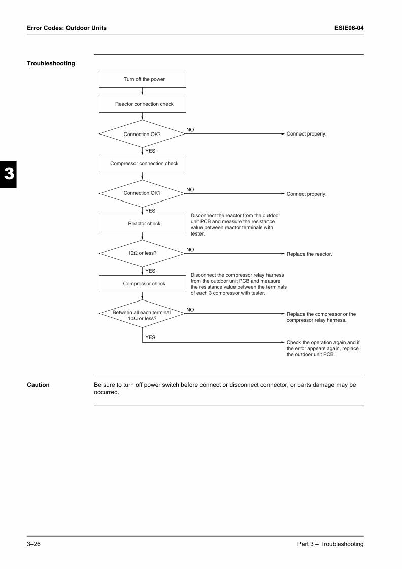
Error Codes: Outdoor Units ESIE06-04
3
1
3
4
5
ESIE06-04.book Page 26 Thursday, November 2, 2006 11:01 AM
Troubleshooting
Caution Be sure to turn off power switch before connect or disconnect connector, or parts damage may be occurred.
NOConnection OK? Connect properly.
Reactor connection check
Turn off the power
Compressor connection check
NOConnection OK? Connect properly.
YES
Reactor check
NO10Ω or less? Replace the reactor.
Replace the compressor or the compressor relay harness.
Disconnect the compressor relay harness from the outdoor unit PCB and measure the resistance value between the terminals of each 3 compressor with tester.
Disconnect the reactor from the outdoor unit PCB and measure the resistance value between reactor terminals with tester.
Check the operation again and if the error appears again, replace the outdoor unit PCB.
YES
Compressor check
NO
YES
Between all each terminal 10Ω or less?
YES
3–26 Part 3 – Troubleshooting

ESIE06-04 Error Codes: Outdoor Units
33
4
5
1
ESIE06-04.book Page 27 Thursday, November 2, 2006 11:01 AM
3.11 “H6” Compressor Startup Failure
Error code H6
Method of malfunction detection
A compressor startup failure is detected by checking the compressor running condition through the position detection circuit.
Malfunction decision conditions
m The compressor fails to start in about 15 seconds after the compressor run command signal is sent.
m Clearing condition: Continuous run for about 5 minutes (normal)
m The system will be shut down if the error occurs 8 times.
Supposed causes m Compressor relay cable disconnected
m Compressor itself defective
m Outdoor unit PCB defective
m Stop valve closed
m Input voltage out of specification
Part 3 – Troubleshooting 3–27

Error Codes: Outdoor Units ESIE06-04
3
1
3
4
5
ESIE06-04.book Page 28 Thursday, November 2, 2006 11:01 AM
Troubleshooting
See also: "Check No.13" on page 3-61
Caution Be sure to turn off power switch before connect or disconnect connector, or parts damage may be occurred.
Replace the outdoor unit PCB, outdoor unit fan.
Replace the outdoor unit PCB.
Reconnect as specified.
∗ Inverter checker Part No.: 1225477
Correct the power supply or replace the outdoor unit PCB.
Replace the compressor.
NO
NO
NO
YES
YES
NO
YES
Normal
DC320±30V?
Electricalsor compressor harnesses
connected asspecified?
Any LED off?
Check the electrolytic capacitor voltage.
Check with the inverter checker (∗).
Turn off the power. Disconnect the harnesses U, V and W.
Check No. 13Check for short-circuit.
3–28 Part 3 – Troubleshooting
ESIE06-04 Error Codes: Outdoor Units
33
4
5
1
ESIE06-04.book Page 29 Thursday, November 2, 2006 11:01 AM
3.12 “H8” CT or Related Abnormality
Error code H8
Method of malfunction detection
A CT or related error is detected by checking the compressor running frequency and CT-detected input current.
Malfunction decision conditions
The compressor running frequency is below 55 Hz and the CT input is below 0.1 V.(The input current is also below 0.5 A.)
m If this error repeats 4 times, the system will be shut down.
m The error counter will reset itself if this or any other error does not occur during the following 60-minute compressor running time (total time).
Supposed causes m Power transistor defective
m Internal wiring broken or in poor contact
m Reactor defective
m Outdoor unit PCB defective
Part 3 – Troubleshooting 3–29
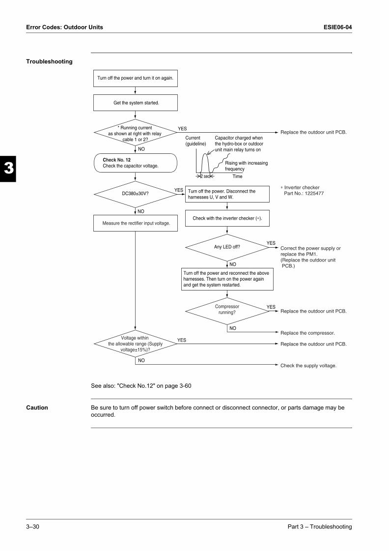
Error Codes: Outdoor Units ESIE06-04
3
1
3
4
5
ESIE06-04.book Page 30 Thursday, November 2, 2006 11:01 AM
Troubleshooting
See also: "Check No.12" on page 3-60
Caution Be sure to turn off power switch before connect or disconnect connector, or parts damage may be occurred.
Replace the outdoor unit PCB.
Check the supply voltage.
Replace the outdoor unit PCB.
Replace the compressor.
Replace the outdoor unit PCB.
Correct the power supply or replace the PM1.(Replace the outdoor unit PCB.)
∗ Inverter checker Part No.: 1225477
YES
Current (guideline)
2 sec Time
Rising with increasingfrequency
Capacitor charged when the hydro-box or outdoorunit main relay turns onNO
NO
YES
YES
NO
* Running current as shown at right with relay
cable 1 or 2?
DC380±30V?
Any LED off?
YES
NO
YES
NO
Compressor running?
Voltage within the allowable range (Supply
voltage±15%)?
Turn off the power and turn it on again.
Get the system started.
Measure the rectifier input voltage.
Turn off the power. Disconnect the harnesses U, V and W.
Check with the inverter checker (∗).
Turn off the power and reconnect the above harnesses. Then turn on the power again and get the system restarted.
Check No. 12Check the capacitor voltage.
3–30 Part 3 – Troubleshooting

ESIE06-04 Error Codes: Outdoor Units
33
4
5
1
ESIE06-04.book Page 31 Thursday, November 2, 2006 11:01 AM
3.13 “P4, J3, J6, H9” Thermistor or Related Abnormality (Outdoor Unit)
Error code P4, J3, J6, H9
Method of malfunction detection
This type of error is detected by checking the thermistor input voltage to the microcomputer.[A thermistor error is detected by checking the temperature.]
Malfunction decision conditions
The thermistor input is above 4.96 V or below 0.04 V with the power on.Error J3 is judged if the discharge pipe thermistor temperature is smaller than the condenser thermistor temperature.
Supposed causes m Connector in poor contact
m Thermistor defective
m Outdoor unit PCB defective
m Hydro-kit PCB defective
m Condenser thermistor defective in the case of J3 error (outdoor unit heat exchanger thermistor in the cooling mode, or Hydro-kit heat exchanger thermistor in the heating mode)
Part 3 – Troubleshooting 3–31

Error Codes: Outdoor Units ESIE06-04
3
1
3
4
5
ESIE06-04.book Page 32 Thursday, November 2, 2006 11:01 AM
Troubleshooting
P4: Radiation fin thermistorJ3: Discharge pipe thermistorJ6: Outdoor heat exchanger thermistorH9: Outdoor air thermistor
See also: "Check No.06" on page 3-53
Caution Be sure to turn off power switch before connect or disconnect connector, or parts damage may be occurred.
Reconnect.
Reconnect.
Replace the following thermistor.• Hydro-box heat exchanger thermistor
Replace the outdoor unit PCB. (Replace the hydro-box PCB.)
Replace defective one(s) of the following thermistors.• Radiation fin thermistor• Discharge pipe temperature thermistor• Outdoor unit heat exchanger temperature thermistor• Outdoor air thermistor
NO
YES
YES
YES
NO
NO
Error displayed again on remote controller?
Connector or thermistor disconnected?
NO
YES
Normal?
hydro-box heat exchanger thermistor
functioning?
Turn on the power again.
Check No. 06Check the thermistor resistance value.
Check No. 06Check the hydro-box heat exchanger thermistor resistance value in the heating mode.
3–32 Part 3 – Troubleshooting

ESIE06-04 Error Codes: Outdoor Units
33
4
5
1
ESIE06-04.book Page 33 Thursday, November 2, 2006 11:01 AM
3.14 “L3” Switch Box Temperature Rise
Error code L3
Method of malfunction detection
An electrical box temperature rise is detected by checking the radiation fin thermistor with the compressor off.
Malfunction decision conditions
With the compressor off, the radiation fin temperature is above 95°C. (Reset is made when the temperature drops below 80°C.)
Supposed causes m Fin temperature rise due to defective outdoor unit fan
m Fin temperature rise due to short-circuit
m Fin thermistor defective
m Connector in poor contact
m Outdoor unit PCB defective
Part 3 – Troubleshooting 3–33

Error Codes: Outdoor Units ESIE06-04
3
1
3
4
5
ESIE06-04.book Page 34 Thursday, November 2, 2006 11:01 AM
Troubleshooting
See also:
m "Check No.06" on page 3-53
m "Check No.07" on page 3-55
m "Check No.09" on page 3-57
Caution Be sure to turn off power switch before connect or disconnect connector, or parts damage may be occurred.
Replace the outdoor unit PCB.
Replace the fan motor.Correct the connectors and fan motor leads.Replace the outdoor unit PCB.
Clean up the radiation fin.
YES
NO
Slightly dirty
Malfunctioning
Too dirty
Functioning
Error again or outdoor unit fan activated?
Check No. 09Check the outdoor unit
fan or related.
NO
YES
Above 95˚C?
Radiation fin dirty?
Turn off the power and turn it on again.
Check the radiation fin temperature.
Check No. 07Check the installation condition.
WARNING
To cool down the electricals, the outdoor unit fan gets started when the radiation fin temperature rises above 95˚C and stops itself when it drops below 80˚C.
3–34 Part 3 – Troubleshooting
ESIE06-04 Error Codes: Outdoor Units
33
4
5
1
ESIE06-04.book Page 35 Thursday, November 2, 2006 11:01 AM
3.15 “L4” Radiation Fin Temperature Rise
Error code L4
Method of malfunction detection
A radiation fin temperature rise is detected by checking the radiation fin thermistor with the compressor on.
Malfunction decision conditions
m If the radiation fin temperature with the compressor on is above 105°C,
m The error is cleared when the temperature drops below 99°C.
m If a radiation fin temperature rise takes place 4 times successively, the system will be shut down.
m The error counter will reset itself if this or any other error does not occur during the following 60-minute compressor running time (total time).
Supposed causes m Fin temperature rise due to defective outdoor unit fan
m Fin temperature rise due to short-circuit
m Fin thermistor defective
m Connector in poor contact
Part 3 – Troubleshooting 3–35

Error Codes: Outdoor Units ESIE06-04
3
1
3
4
5
ESIE06-04.book Page 36 Thursday, November 2, 2006 11:01 AM
Troubleshooting
See also:
m "Check No.06" on page 3-53
m "Check No.07" on page 3-55
m "Check No.09" on page 3-57
Caution Be sure to turn off power switch before connect or disconnect connector, or parts damage may be occurred.
Check the power transistor and fin for looseness. If they are found to be fit tightly, replace the PCB or the power transistor.
Replace the fan motor.Correct the connectors and fan motor leads.Replace the outdoor unit PCB.
Clean up the radiation fin.
YES
NO
Slightly dirty
Malfunctioning
Too dirty
Functioning
Error displayed again?
Check No. 09Check the outdoor unit
fan or related.
NO
YES
Above 105˚C?
Radiation fin dirty?
Turn off the power and turn it on again to get the system started.
Check the radiation fin temperature.
Check No. 07Check the installation condition.
3–36 Part 3 – Troubleshooting
ESIE06-04 Error Codes: Outdoor Units
33
4
5
1
ESIE06-04.book Page 37 Thursday, November 2, 2006 11:01 AM
3.16 “L5” Output Over Current Detection
Error code L5
Method of malfunction detection
An output over-current is detected by checking the current that flows in the inverter DC section.
Malfunction decision conditions
m A position signal error occurs while the compressor is running.
m A speed error occurs while the compressor is running.
m An output over-current input is fed from the output over-current detection circuit to the microcomputer.
m The system will be shut down if the error occurs 16 times.
m Clearing condition: Continuous run for about 5 minutes (normal)
Supposed causes m Over-current due to defective power transistor
m Over-current due to wrong internal wiring
m Over-current due to abnormal supply voltage
m Over-current due to defective PCB
m Error detection due to defective PCB
m Over-current due to closed stop valve
m Over-current due to compressor failure
m Over-current due to poor installation condition
Part 3 – Troubleshooting 3–37
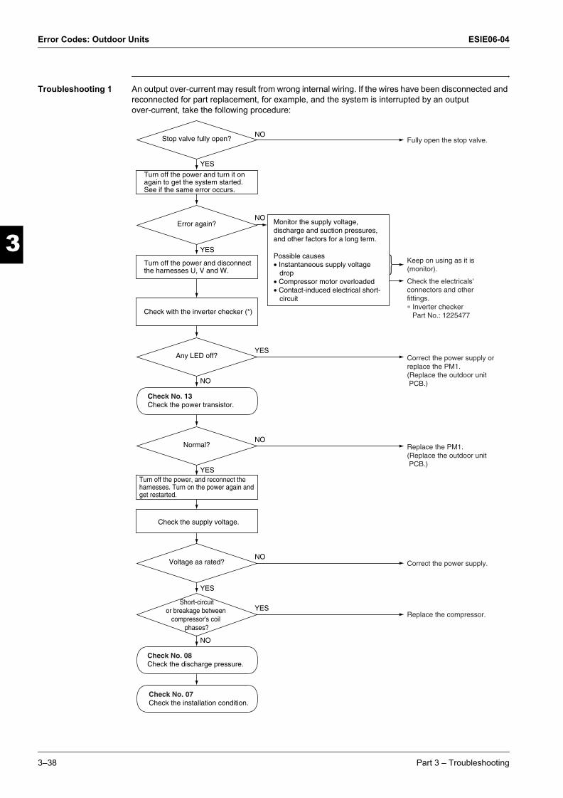
Error Codes: Outdoor Units ESIE06-04
3
1
3
4
5
ESIE06-04.book Page 38 Thursday, November 2, 2006 11:01 AM
Troubleshooting 1 An output over-current may result from wrong internal wiring. If the wires have been disconnected and reconnected for part replacement, for example, and the system is interrupted by an output over-current, take the following procedure:
Replace the compressor.
Correct the power supply.
Replace the PM1.(Replace the outdoor unit PCB.)
Correct the power supply or replace the PM1.(Replace the outdoor unit PCB.)
Check the electricals' connectors and other fittings.∗ Inverter checker Part No.: 1225477
Keep on using as it is (monitor).
Fully open the stop valve.NO
YES
NO
YES
Stop valve fully open?
Error again?
NO
YES
Voltage as rated?
YES
NO
Short-circuitor breakage between
compressor's coil phases?
NO
YES
Normal?
YES
NO
Any LED off?
Turn off the power and turn it on again to get the system started. See if the same error occurs.
Turn off the power and disconnect the harnesses U, V and W.
Check with the inverter checker (*)
Monitor the supply voltage, discharge and suction pressures, and other factors for a long term.
Possible causes• Instantaneous supply voltage drop• Compressor motor overloaded• Contact-induced electrical short- circuit
Turn off the power, and reconnect the harnesses. Turn on the power again and get restarted.
Check the supply voltage.
Check No. 13Check the power transistor.
Check No. 08Check the discharge pressure.
Check No. 07Check the installation condition.
3–38 Part 3 – Troubleshooting

ESIE06-04 Error Codes: Outdoor Units
33
4
5
1
ESIE06-04.book Page 39 Thursday, November 2, 2006 11:01 AM
See also:
m "Check No.07" on page 3-55
m "Check No.08" on page 3-56
m "Check No.13" on page 3-61
Caution Be sure to turn off power switch before connect or disconnect connector, or parts damage may be occurred.
Part 3 – Troubleshooting 3–39
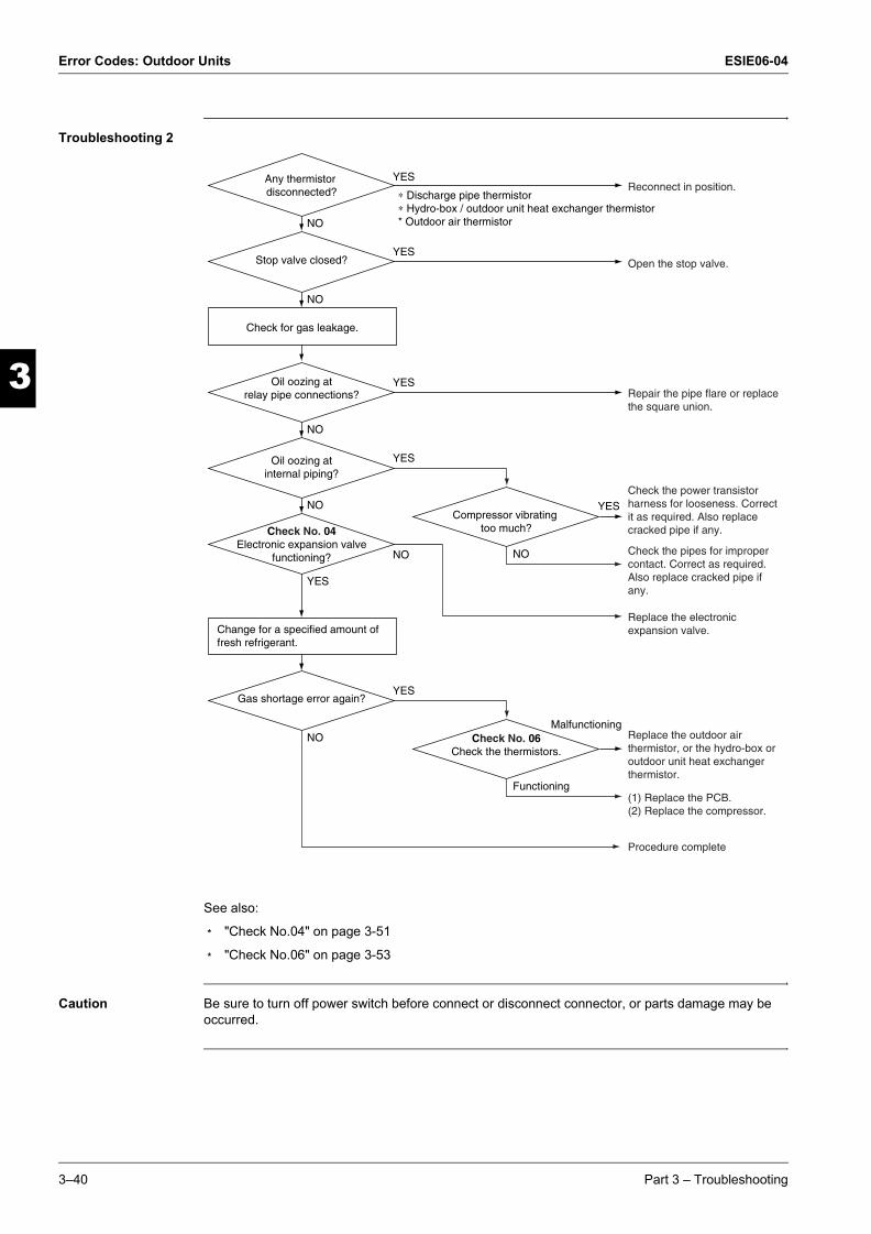
Error Codes: Outdoor Units ESIE06-04
3
1
3
4
5
ESIE06-04.book Page 40 Thursday, November 2, 2006 11:01 AM
Troubleshooting 2
See also:
m "Check No.04" on page 3-51
m "Check No.06" on page 3-53
Caution Be sure to turn off power switch before connect or disconnect connector, or parts damage may be occurred.
Reconnect in position.
Open the stop valve.
Repair the pipe flare or replace the square union.
Check the power transistor harness for looseness. Correct it as required. Also replace cracked pipe if any.
Check the pipes for improper contact. Correct as required. Also replace cracked pipe if any.
Replace the electronic expansion valve.
Replace the outdoor air thermistor, or the hydro-box or outdoor unit heat exchanger thermistor.
(1) Replace the PCB.(2) Replace the compressor.
Procedure complete
YES
Malfunctioning
NO
NO
YES
Any thermistor disconnected?
Stop valve closed?
YES
NO
Gas shortage error again?
Functioning
Check No. 06Check the thermistors.
YESOil oozing at internal piping?
NO
YES
Check No. 04Electronic expansion valve
functioning?
YES
NO
Oil oozing at relay pipe connections?
Check for gas leakage.
Change for a specified amount of fresh refrigerant.
NO
YESCompressor vibrating
too much?
∗ Discharge pipe thermistor∗ Hydro-box / outdoor unit heat exchanger thermistor* Outdoor air thermistor
NO
3–40 Part 3 – Troubleshooting

ESIE06-04 Error Codes: System Malfunctions
1
ESIE06-04.book Page 41 Thursday, November 2, 2006 11:01 AM
Part 3
33
4
5
4 Error Codes: System Malfunctions
4.1 What Is in This Chapter?
Introduction In the first stage of the troubleshooting sequence, it is important to correctly interpret the error code on the remote controller display. The error code helps you to find the cause of the problem.
Overview This chapter contains the following topics:
Topic See page
4.2–“U0” Insufficient Gas 3–42
4.3–“U2” Low-voltage Detection or Over-voltage Detection 3–44
4.4–“U4” Signal Transmission Error (between Hydro-kit and Outdoor Units) 3–45
4.5–“U7” Malfunction of Transmission between Remote Controller and Control box 3–47
Part 3 – Troubleshooting 3–41
Error Codes: System Malfunctions ESIE06-04
3
1
3
4
5
ESIE06-04.book Page 42 Thursday, November 2, 2006 11:01 AM
4.2 “U0” Insufficient Gas
Error code U0
Method of malfunction detection
Gas shortage detection I:
A gas shortage is detected by checking the CT-detected input current value and the compressor running frequency.
Gas shortage detection II:
A gas shortage is detected by checking the difference between Hydro-kit heat exchanger temperature and room temperature as well as the difference between outdoor unit heat exchanger temperature and room temperature.
Malfunction decision conditions
Gas shortage detection I :
DC current ≤ (A/Hz) × Output frequency +However, when the status of running frequency > 55 (Hz) is kept on for a certain time.
Note: The values are different from model to model.
Gas shortage detection II :
If a gas shortage error takes place 4 times successively, the system will be shut down. The error counter will reset itself if this or any other error does not occur during the following 60-minute compressor running time (total time).
Supposed causes m Refrigerant shortage (refrigerant leakage)
m Poor compression performance of compressor
m Discharge pipe thermistor disconnected, or Hydro-kit or outdoor unit heat exchanger thermistor disconnected, room or outside air temperature thermistor disconnected
m Stop valve closed
m Electronic expansion valve defective
50/60/71 class 27 / 1000 2.5
3–42 Part 3 – Troubleshooting

ESIE06-04 Error Codes: System Malfunctions
33
4
5
1
ESIE06-04.book Page 43 Thursday, November 2, 2006 11:01 AM
Troubleshooting
See also:
m "Check No.04" on page 3-51
m "Check No.06" on page 3-53
Caution Be sure to turn off power switch before connect or disconnect connector, or parts damage may be occurred.
∗ Discharge pipe thermistor∗ Hydro-box / outdoor unit heat exchanger thermistor∗ Room temperature thermistor∗ Outdoor air thermistor
Reconnect in position.
Open the stop valve.
Repair the pipe flare or replace the square union.
Check the power transistor harness for looseness. Correct it as required. Also replace cracked pipe if any.
Check the pipes for improper contact. Correct as required. Also replace cracked pipe if any.
Replace the electronic expansion valve.
Replace the room temperature or outdoor air thermistor, or the hydro-box or outdoor unit heat exchanger thermistor.
(1) Replace the PCB.(2) Replace the compressor.
Procedure complete.
YES
Malfunctioning
NO
NO
YES
Any thermistor disconnected?
Stop valve closed?
YES
NO
Gas shortage error again?
Functioning
Check No. 06Check the thermistors.
YES Oil oozing at internal piping?
NO
YES
Check No. 04Electronic expansion valve
functioning?
YES
NO
Oil oozing at relay pipe connections?
Check for gas leakage.
Change for a specified amount of fresh refrigerant.
NO
YESCompressor vibrating too much?
NO
Part 3 – Troubleshooting 3–43

Error Codes: System Malfunctions ESIE06-04
3
1
3
4
5
ESIE06-04.book Page 44 Thursday, November 2, 2006 11:01 AM
4.3 “U2” Low-voltage Detection or Over-voltage Detection
Error code U2
Method of malfunction detection
An abnormal voltage rise or drop is detected by checking the detection circuit or DC voltage detection circuit.
Malfunction decision conditions
m An over-voltage signal is fed from the over-voltage detection circuit to the microcomputer, or the voltage being detected by the DC voltage detection circuit is judged to be below 150 V for 0.1 second.
m The system will be shut down if the error occurs 16 times.
m Clearing condition: Continuous run for about 60 minutes (normal)
Supposed causes m Supply voltage not as specified
m Over-voltage detector or DC voltage detection circuit defective
m PAM control part(s) defective
Troubleshooting
Caution Be sure to turn off power switch before connect or disconnect connector, or parts damage may be occurred.
Correct the power supply.
Check for such factors for a long term.∗ Try to get restarted a couple of times.
Replace the PM1.(Replace the outdoor unit PCB.)
NO
YES
NO
Repeat a couple of times.
Supply voltage as specified?
Turn on the power again.System restarted?
YES
Check the supply voltage.
Disturbance factors∗ Noise ∗ Power supply distortion
(Precaution before turning on the power again)Make sure the power has been off for at least 30 seconds.
3–44 Part 3 – Troubleshooting

ESIE06-04 Error Codes: System Malfunctions
33
4
5
1
ESIE06-04.book Page 45 Thursday, November 2, 2006 11:01 AM
4.4 “U4” Signal Transmission Error (between Hydro-kit and Outdoor Units)
Error code U4
Method of malfunction detection
The data received from the outdoor unit in Hydro-kit-outdoor unit signal transmission is checked whether it is normal.
Malfunction decision conditions
When the data sent from the outdoor unit cannot be received normally, or when the content of the data is abnormal.
Supposed causes m Faulty outdoor unit PCB.
m Faulty Hydro-kit PCB.
m Hydro-kit-outdoor unit signal transmission error due to wiring error.
m Hydro-kit-outdoor unit signal transmission error due to disturbed power supply waveform.
m Hydro-kit-outdoor unit signal transmission error due to breaking of wire in the connection wires between the Hydro-kit and outdoor units.
Part 3 – Troubleshooting 3–45

Error Codes: System Malfunctions ESIE06-04
3
1
3
4
5
ESIE06-04.book Page 46 Thursday, November 2, 2006 11:01 AM
Troubleshooting
See also: "Check No.10" on page 3-58
Caution Be sure to turn off power switch before connect or disconnect connector, or parts damage may be occurred.
Correct the hydro-box - outdoor unit connection wires.
Diagnose the outdoor unit.
Replace hydro-box control PCB.
Replace the connection wires between the indoor and outdoor units.
Locate the cause of the disturbance of the power supply waveform, and correct it.
YES
YES
NO
NO
YES
YES
NO
NO
Check No. 10Check power supply waveform.
Check the hydro-box - outdoor unit connection wires.
Check the outdoor unit's LED A.
Check the voltage of the hydro-box - outdoor unit connection wires between No. 1 and No. 2, and between No 2 and No. 3.
Is there any wiring error?
Is LED A flashing?
Is the voltage 0 V?
Is there any disturbance?
3–46 Part 3 – Troubleshooting

ESIE06-04 Error Codes: System Malfunctions
33
4
5
1
ESIE06-04.book Page 47 Thursday, November 2, 2006 11:01 AM
4.5 “U7” Malfunction of Transmission between Remote Controller and Control box
Error code U7
Method of malfunction detection
Communication error between microcomputer mounted on the main microcomputer and PM1.
Malfunction decision conditions
m When the data sent from the PM1 can not be received successively for 9 sec.
m The abnormality is determined if the above fault conditions occurs once.
m Fault counter is reset when the data from the PM1 can be successfully received.
Supposed causes m Defective outdoor unit PCB
Troubleshooting
Caution Be sure to turn off power switch before connect or disconnect connector, or parts damage may be occurred.
Replace the outdoor unit PCB.
The cause can be an external factor other than the malfunction.Monitor in long term.
NO
Error again?YES
Turn the power off and turn it on again.
Part 3 – Troubleshooting 3–47

Error Codes: System Malfunctions ESIE06-04
3
1
3
4
5
ESIE06-04.book Page 48 Thursday, November 2, 2006 11:01 AM
3–48 Part 3 – Troubleshooting

ESIE06-04 Additional Checks for Troubleshooting
1
ESIE06-04.book Page 49 Thursday, November 2, 2006 11:01 AM
Part 3
33
4
5
5 Additional Checks for Troubleshooting
5.1 What Is in This Chapter?
Introduction This chapter explains how you must check the units to carry out troubleshooting correctly.
Overview This chapter contains the following topics:
Topic See page
5.2–Fan Motor Connector Output Check 3–50
5.3–Electronic Expansion Valve Check 3–51
5.4–Four Way Valve Performance Check 3–52
5.5–Thermistor Resistance Check 3–53
5.6–Installation Condition Check 3–55
5.7–Discharge Pressure Check 3–56
5.8–Outdoor Unit Fan System Check (With DC Motor) 3–57
5.9–Power Supply Waveforms Check 3–58
5.10–Inverter Units Refrigerant System Check 3–59
5.11–Capacitor Voltage Check 3–60
5.12–Power Transistor Check 3–61
5.13–Main Circuit Electrolytic Capacitor Check 3–62
5.14–Turning Speed Pulse Input on the Outdoor Unit PCB Check 3–63
5.15–“Inverter Checker” Check 3–64
Part 3 – Troubleshooting 3–49

Additional Checks for Troubleshooting ESIE06-04
3
1
3
4
5
ESIE06-04.book Page 50 Thursday, November 2, 2006 11:01 AM
5.2 Fan Motor Connector Output Check
Check No.01 1 Check connector connection.
2 Check motor power supply voltage output (pins 4-7).
3 Check motor control voltage (pins 4-3).
4 Check rotation command voltage output (pins 4-2).
5 Check rotation pulse input (pins 4-1).
7654321
Motor power supply voltageUnusedUnusedP.0V (reference potential)Motor control voltage (15 VDC)Rotation command voltage (1~ 6 VDC)Rotation pulse input
S1
3–50 Part 3 – Troubleshooting

ESIE06-04 Additional Checks for Troubleshooting
33
4
5
1
ESIE06-04.book Page 51 Thursday, November 2, 2006 11:01 AM
5.3 Electronic Expansion Valve Check
Check No.04 Conduct the followings to check the electronic expansion valve (EV).
1 Check to see if the EV connector is correctly inserted in the PCB. Compare the EV unit and the connector number.
2 Turn the power off and back on again, and check to see if all the EVs generate latching sound.
3 If any of the EVs does not generate latching noise in the above step 2, disconnect that connector and check the conductivity using a tester.
Check the conductivity between pins 1, 3 and 6, and between pins 2, 4 and 5. If there is no conductivity between the pins, the EV coil is faulty.
4 If no EV generates latching sound in the above step 2, the outdoor unit PCB is faulty.
5 If the conductivity is confirmed in the above step 2, mount a good coil (which generated latching sound) in the EV unit that did not generate latching sound, and check to see if that EV generates latching sound.
m If latching sound is generated, the outdoor unit PCB is faulty.
m If latching sound is not generated, the EV unit is faulty.
Note Please note that the latching sound varies depending on the valve type.
Harness 6P
6P Connector Check
5-25-46-16-3
1 2 3 4 5 6
Part 3 – Troubleshooting 3–51

Additional Checks for Troubleshooting ESIE06-04
3
1
3
4
5
ESIE06-04.book Page 52 Thursday, November 2, 2006 11:01 AM
5.4 Four Way Valve Performance Check
Check No.05
Replace the four way valve coil.
Replace the outdoor unit PCB.
Replace the four way valve.
NO
∗ Four way valve coil Cooling / dry : No continuity Heating : Continuity
YES
YES
NO
S80 voltageat DC 220-240 V with
compressor on? (Fig. 1)
Four way valvecoil resistance at
1500 ohms?
Turn off the power and turn it on again.
Start the heating-mode run.
Disconnect the four way valve coil from the connector and check the continuity.
Voltage at S80
DC220-240V
CompressorON Time
3–52 Part 3 – Troubleshooting

ESIE06-04 Additional Checks for Troubleshooting
33
4
5
1
ESIE06-04.book Page 53 Thursday, November 2, 2006 11:01 AM
5.5 Thermistor Resistance Check
Check No.06 Remove the connectors of the thermistors on the PCB, and measure the resistance of each thermistor using tester.
The relationship between normal temperature and resistance is shown in the graph and the table below:
Hydro-kit
3SA48002
R25°C=20kΩ
B=3990
-20 197.8 kΩ
-15 148.2 kΩ
-10 112.0 kΩ
-5 85.52 kΩ
0 65.84 kΩ
5 51.05 kΩ
10 39.91 kΩ
15 31.44 kΩ
20 24.95 kΩ
25 19.94 kΩ
30 16.04 kΩ
35 12.99 kΩ
40 10.58 kΩ
45 8.669 kΩ
50 7.143 kΩ
Part 3 – Troubleshooting 3–53
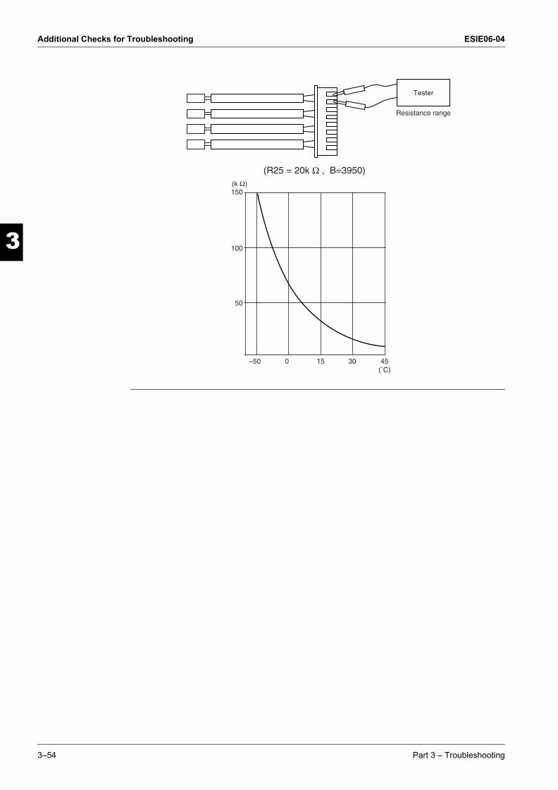
Additional Checks for Troubleshooting ESIE06-04
3
1
3
4
5
ESIE06-04.book Page 54 Thursday, November 2, 2006 11:01 AM
Tester
Resistance range
(R25 = 20k Ω , B=3950)(k Ω)150
100
50
–50 0 15 30 45(˚C)
3–54 Part 3 – Troubleshooting

ESIE06-04 Additional Checks for Troubleshooting
33
4
5
1
ESIE06-04.book Page 55 Thursday, November 2, 2006 11:01 AM
5.6 Installation Condition Check
Check No.07
Change the position of the air discharge grille or the installation location.
Change the position of the air discharge grille or the installation location.
Clean the heat exchanger.
Check the outside air temperature (temperature of air taken in by the outdoor unit). (The outside air temperature shall be 43˚C or lower.)
Change the installation location or direction.
Normal
Abnormal
YES
YES
YES
NO
NO
NO
Installation condition check
Check the allowable
dimensions of the air suctionand discharge
area.
Is the heat exchangervery dirty?
Isthe air flow
blocked by obstacles orwinds blowing in theopposite direction?
Doesthe discharged
air from other outdoorunit cause an increase of
the suction airtemperature?
Part 3 – Troubleshooting 3–55

Additional Checks for Troubleshooting ESIE06-04
3
1
3
4
5
ESIE06-04.book Page 56 Thursday, November 2, 2006 11:01 AM
5.7 Discharge Pressure Check
Check No.08
Replace compessor.
Open the stop valve.
Replace the pipe installed at the site.
Clean.
Replace the compressor.YES
YES
YES
NO
NO
NO
NO
Discharge pressure check
Is the stop valve open?
YES
High
Is theconnection pipe
deformed?
Are the heat exchanger and
air filter dirty?
3–56 Part 3 – Troubleshooting
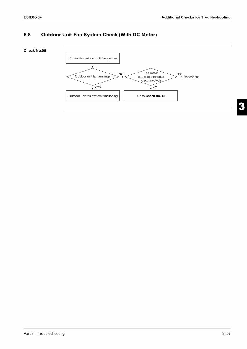
ESIE06-04 Additional Checks for Troubleshooting
33
4
5
1
ESIE06-04.book Page 57 Thursday, November 2, 2006 11:01 AM
5.8 Outdoor Unit Fan System Check (With DC Motor)
Check No.09
Reconnect.
YES
Outdoor unit fan running?Fan motor
lead wire connector disconnected?
YESNO
NO
Check the outdoor unit fan system.
Outdoor unit fan system functioning. Go to Check No. 15.
Part 3 – Troubleshooting 3–57

Additional Checks for Troubleshooting ESIE06-04
3
1
3
4
5
ESIE06-04.book Page 58 Thursday, November 2, 2006 11:01 AM
5.9 Power Supply Waveforms Check
Check No.10 Measure the power supply waveform between pins 1 and 3 on the terminal board, and check the waveform disturbance.
m Check to see if the power supply waveform is a sine wave.
m Check to see if there is waveform disturbance near the zero cross (sections circled).
3–58 Part 3 – Troubleshooting

ESIE06-04 Additional Checks for Troubleshooting
33
4
5
1
ESIE06-04.book Page 59 Thursday, November 2, 2006 11:01 AM
5.10 Inverter Units Refrigerant System Check
Check No.11
Correct the problem.
Conduct vacuum drying.
Replace the refrigerant.
Conduct the check after operating theequipment for a sufficient length of time.
YES
YES
YES
NO
NO
Refrigerant system check
Check for gas leaks.See the section on insufficient gas detection.
Isthe discharge
thermistor disconnected fromthe holder?
Is any moisturefound in sight glass?
Part 3 – Troubleshooting 3–59

Additional Checks for Troubleshooting ESIE06-04
3
1
3
4
5
ESIE06-04.book Page 60 Thursday, November 2, 2006 11:01 AM
5.11 Capacitor Voltage Check
Check No.12 Before this checking, be sure to check the main circuit for short-circuit.
m Checking the capacitor voltage
m With the circuit breaker still on, measure the voltage according to the drawing of the model in question. Be careful never to touch any live parts
OL lead wire
Thermistor lead wire
Fan motor lead wireElectronic expansion valvelead wire
Reversing solenoid valve lead wire(Heat pump type only)
Compressor lead wire
Reactor lead wire
Multimeter(DC voltage range)
3–60 Part 3 – Troubleshooting
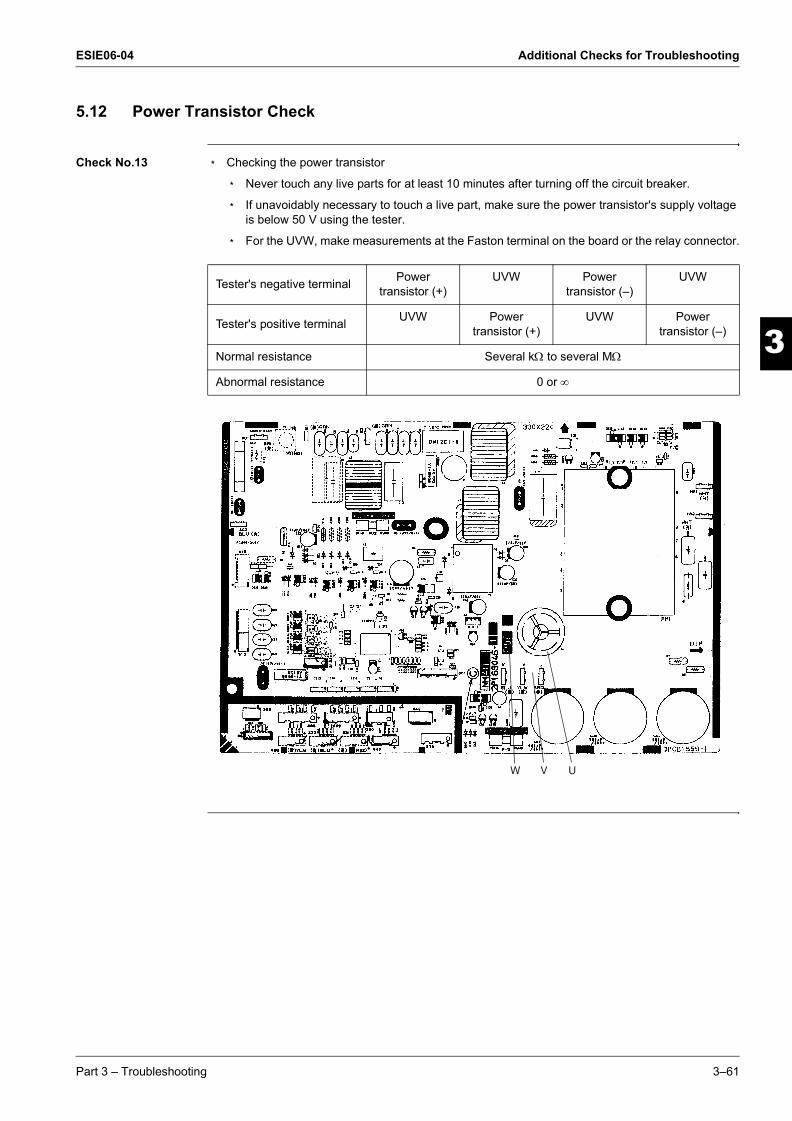
ESIE06-04 Additional Checks for Troubleshooting
33
4
5
1
ESIE06-04.book Page 61 Thursday, November 2, 2006 11:01 AM
5.12 Power Transistor Check
Check No.13 m Checking the power transistor
m Never touch any live parts for at least 10 minutes after turning off the circuit breaker.
m If unavoidably necessary to touch a live part, make sure the power transistor's supply voltage is below 50 V using the tester.
m For the UVW, make measurements at the Faston terminal on the board or the relay connector.
Tester's negative terminal Power transistor (+)
UVW Power transistor (–)
UVW
Tester's positive terminal UVW Power transistor (+)
UVW Power transistor (–)
Normal resistance Several kΩ to several MΩ
Abnormal resistance 0 or ∞
W V U
Part 3 – Troubleshooting 3–61

Additional Checks for Troubleshooting ESIE06-04
3
1
3
4
5
ESIE06-04.book Page 62 Thursday, November 2, 2006 11:01 AM
5.13 Main Circuit Electrolytic Capacitor Check
Check No.14 m Checking the main circuit electrolytic capacitor
m Never touch any live parts for at least 10 minutes after turning off the circuit breaker.
m If unavoidably necessary to touch a live part, make sure there is no DC voltage using the tester.
m Check the continuity with the tester. Reverse the pins and make sure there is continuity.
If the pointer does not swing at all,or if it swings all the waybut does not return,it means the capacitor malfunction.
When the pointer swings,it means the capacitorfunctions.
Keep the tester in theresistance measuring range.
3–62 Part 3 – Troubleshooting

ESIE06-04 Additional Checks for Troubleshooting
33
4
5
1
ESIE06-04.book Page 63 Thursday, November 2, 2006 11:01 AM
5.14 Turning Speed Pulse Input on the Outdoor Unit PCB Check
Check No.15 Propeller fan motor
Make sure the voltage of 320±30V is being applied.
1 Stop the operation first and then the power off, and disconnect the connector S70.
2 Make sure there is about DC 320 V between pins 4 and 7.
3 With the system and the power still off, reconnect the connector S70.
4 Make a turn of the fan motor with a hand, and make sure the pulse (0-15 V) appears twice at pins 1 and 4.
If the fuse for fan motor protection is blown out, the outdoor-unit fan may also be in trouble. Check the fan too.
If the voltage in Step (2) is not applied, it means the PCB is defective. Replace the PCB.
If the pulse in Step (4) is not available, it means the Hall IC is defective. Replace the DC fan motor.If there are both the voltage (2) and the pulse (4), replace the PCB.
∗Propeller fan motor: S70
1234567 DC320V
S70
PCB
Turning speed pulse input (0-15 V)
15V
Part 3 – Troubleshooting 3–63

Additional Checks for Troubleshooting ESIE06-04
3
1
3
4
5
ESIE06-04.book Page 64 Thursday, November 2, 2006 11:01 AM
5.15 “Inverter Checker” Check
Check No.16
Characteristics If an abnormal stop occurs due to compressor startup failure or overcurrent output when using the inverter unit, it is difficult to judge whether it results from the compressor failure or another failure (control PC Board, power transistor, etc.). The inverter analyzer makes it possible to judge the cause of trouble easily and securely. (Connect this analyzer as a quasi compressor instead of a compressor and check the output of the inverter.)
Operation method 1 Be sure to turn the power off.
2 Install the inverter analyzer instead of a compressor.
Note: Make sure the charged voltage of the built-in smoothing electrolytic capacitor drops to 10 VDC or below before carrying out the service work.
Reference:
If the connector terminal of the compressor is not a faston terminal (difficult to remove the wire on the terminal), it is possible to connect a wire available on site to the unit from the output side of the PCB. (Do not connect it to the compressor at the same time, otherwise it may result in incorrect detection.)
3 Turn the power on and operate the air conditioner.
(1) Remove the faston terminalsfrom the terminal block ofthe compressor.
(2) Connect the faston terminalsto the terminals of the InverterAnalyzer.
Be careful not to touch the terminals(U,V,W) with each other. Otherwise, high voltage is applied.
Compressor
Inverter Analyzer
3–64 Part 3 – Troubleshooting

ESIE06-04 Additional Checks for Troubleshooting
33
4
5
1
ESIE06-04.book Page 65 Thursday, November 2, 2006 11:01 AM
Diagnose method Diagnose can be made according to 6 LEDs lighting status as follows:
1 When all LEDs are lit uniformly, a compressor malfunction (to be replaced) has occured.
2 When some of the LEDs are not lit (LEDs are not lit or go off, etc.), check the individual power transistor. (See "Check No.15")
m When the power transistor and the control PCB are integrated, replace the control PCB.
m When the power transistor can be checked individually, check the resistance value. (See "Check No.15")
If NG, the power transistor may have a failure. Replace the power transistor.
If the power transistor is normal, check if there is any solder cracking on the filter PCB.
m If any solder cracking is found, replace the filter PCB (or repair the soldered section)
m If the filter PCB is normal, replace the control PCB.
Caution m When the output frequency is low, yhe LED flashes slowly. As the frequency increases, the LED flashes quickly. (It looks like the LED is lit.)µ
m If the operation is carried out with no load (the condition of the compressor is disconnected), some of the units may stop operation with “CT system error” (due to no electric current) or “startup failure” (because the compressor does not turn). In this case, check if the LED is flashing during “operation” to “malfunction stop”. (Refer to the Service Manual of each air conditioner to check whether the alarm LEDs for CT system, startup failure, etc. are provided or not.)
m On completion of diagnose by this checker, be sure to re-crimp the faston terminal before restting the system. (Otherwise, the terminal may be burned due to loosening.)
This size is shortenedby “crimp”.
Direction of crimp
Faston terminal
Part 3 – Troubleshooting 3–65

Additional Checks for Troubleshooting ESIE06-04
3
1
3
4
5
ESIE06-04.book Page 66 Thursday, November 2, 2006 11:01 AM
3–66 Part 3 – Troubleshooting

ESIE06-04
4
3
4
5
4
ESIE06-04.book Page 1 Thursday, November 2, 2006 11:01 AM
Part 4Commissioning and
Test Run
What is in this part? This part contains the following chapters:
Chapter See page
1–Pre-Test Run Checks 4–3
2–Field settings 4–9
3–Operation Range and Test Operation 4–19
Part 4 – Commissioning and Test Run 4–1

ESIE06-04
3
1
4
5
ESIE06-04.book Page 2 Thursday, November 2, 2006 11:01 AM
4–2 Part 4 – Commissioning and Test Run

ESIE06-04 Pre-Test Run Checks
1
ESIE06-04.book Page 3 Thursday, November 2, 2006 11:01 AM
Part 4
3
4
5
1 Pre-Test Run Checks
1.1 What Is in This Chapter?
Introduction This chapter contains the following information:
m Checking the water circuit
m Checking the water volume and expansion vessel pre-pressure
m Checks before test run
m Test run checks
Overview This chapter contains the following topics:
Topic See page
1.2–Test Run Checks for Water Pipework 4–4
1.3–General Test Run Checks 4–7
Part 4 – Commissioning and Test Run 4–3
Pre-Test Run Checks ESIE06-04
3
1
4
5
ESIE06-04.book Page 4 Thursday, November 2, 2006 11:01 AM
1.2 Test Run Checks for Water Pipework
Checking the water circuit
The units have a water inlet and water outlet for connection to a water circuit. This circuit must be provided by a licensed technician and must comply with all relevant European and national regulations.
Caution !
The unit is only to be used in a closed water system. Application in an open water circuit can lead to excessive corrosion of the water piping.
Before continuing the installation of the unit, check the following points:
m Two shut-off valves are delivered with the unit. To facilitate service and maintenance, install one at the water inlet and one at the water outlet of the unit.
m Drain taps must be provided at all low points of the system to permit complete drainage of the circuit. Two drain valves are provided inside the unit.
m Air vents must be provided at all high points of the system. The vents should be located at points which are easily accessible for servicing. An automatic air purge is provided inside the unit. Check that this air purge valve is not tightened too much so that automatic release of air in the water circuit remains possible.
m Take care that the components installed in the field piping can withstand the water pressure.
Checking the water volume and expansion vessel pre-pressure
The unit is equipped with an expansion vessel of 6 litre which has a default pre-pressure of 1 bar.
To assure proper operation of the unit, the pre-pressure of the expansion vessel might need to be adjusted and the minimum and maximum water volume must be checked.
1 Check that the total water volume in the installation is 10 l minimum.
Note: m In most air conditioning applications this minimum water volume will have a satisfying result.m In critical processes or in rooms with a high heat load though, extra water volume might be
required.
2 Using the table below, determine if the expansion vessel pre-pressure requires adjustment.
4–4 Part 4 – Commissioning and Test Run

ESIE06-04 Pre-Test Run Checks
3
4
5
1
ESIE06-04.book Page 5 Thursday, November 2, 2006 11:01 AM
3 Using the table and instructions below, determine if the total water volume in the installation is below the maximum allowed water volume.
(a) Installation height difference: height difference (m) between the highest point of the water circuit and the unit. If the unit is located at the highest point of the installation, the installation height is considered 0 m.
Calculating the pre-pressure of the expansion vessel
The pre-pressure (Pg) to be set depends on the maximum installation height difference (H) and is calculated as below:
Pg = (H/10+0.3) bar
Checking the maximum allowed water volume
To determine the maximum allowed water volume in the entire circuit, proceed as follows:
1 Determine for the calculated pre-pressure (Pg) the corresponding maximum water volume using the graph below.
2 Check that the total water volume in the entire water circuit is lower than this value.
If this is not the case, the expansion vessel inside the unit is too small for the installation.
Installation height difference(a)
Water volume
< 300 l (EWAQ)< 170 l (EWYQ)
> 300 l (EWAQ)> 170 l (EWYQ)
< 7 m No pre-pressure adjustment required Actions required:
m pre-pressure must be decreased, calculate according to "Calculating the pre-pressure of the expansion vessel"
m check if the water volume is lower than maximum allowed water volume (use graph below)
> 7 m Actions required:
m pre-pressure must be increased, calculate according to "Calculating the pre-pressure of the expansion vessel"
m check if the water volume is lower than maximum allowed water volume (use graph below)
Expansion vessel of the unit too small for the installation.
0.30.5
1
1.5
2
2.5
100500 10 150 200 250 300 350 400 450maximum water volume [l]
pre-
pres
sure
[bar
]
EWAQ
EWYQ
Part 4 – Commissioning and Test Run 4–5
Pre-Test Run Checks ESIE06-04
3
1
4
5
ESIE06-04.book Page 6 Thursday, November 2, 2006 11:01 AM
Example 1
A heat pump model is installed 5 m below the highest point in the water circuit. The total water volume in the water circuit is 100 l.
In this example, no action or adjustment is required.
Example 2
A heat pump model is installed 4 meter below the highest point in the water circuit. The total water volume in the water circuit is 190 l.
Result:
m Since 190 l is higher than 170 l, the pre-pressure must be decreased (see table above).
m The required pre-pressure is: Pg = (H/10 + 0.3) bar = (4/10 + 0.3) bar = 0.7 bar
m The corresponding maximum water volume can be read from the graph: approximately 200 l.
m Since the total water volume (190 l) is below the maximum water volume (200 l), the expansion vessel suffices for the installation.
4–6 Part 4 – Commissioning and Test Run

ESIE06-04 Pre-Test Run Checks
3
4
5
1
ESIE06-04.book Page 7 Thursday, November 2, 2006 11:01 AM
1.3 General Test Run Checks
Checks before test run
Before carrying out a test run, proceed as follows:
Test run checks To carry out a test run, check the following:
m Check that the temperature setting of the remote controller is at the lowest level in cooling/heating mode or use test mode.
m Go through the following checklist:
Step Action
1 Make sure the voltage at the primary side of the safety breaker is:
m 230 V ± 10% for 1-phase units
m 400 V ± 10% for 3-phase units
2 Fully open the liquid and the gas stop valve.
3 Full open shut-off valves.
Checkpoints Cautions or warnings
Are all units securely installed? m Dangerous for turning over during storm.
m Possible damage to pipe connections.
Is the earth wire installed according to the applicable local standard?
Dangerous if electric leakage occurs.
Are all air inlets and outlets of the outdoor unit unobstructed?
Poor performance.
Does the drain flow out smoothly? Water leakage.
Is piping adequately heat-insulated? Water leakage.
Have the connections been checked for gas leakage?
m Poor performance.
m Stop.
Is the supply voltage conform to the specifications on the name plate?
Incorrect operation.
Are the cable sizes as specified and according to local regulations?
Damage of cables.
Are the remote controller signals received by the unit?
No operation.
Be sure that minimum waterflow of 12 litres/min. is garantueed.
System stop error code.
Be sure to install an earth leakage protector. Failure to do so may cause electrical shock.
Be sure to use a dedicated power supply for each appliance (outdoor, ...)
Make sure shut off valves are correctly installed.
Operating the system with closed valves will damage pump. System stop.
Part 4 – Commissioning and Test Run 4–7
Pre-Test Run Checks ESIE06-04
3
1
4
5
ESIE06-04.book Page 8 Thursday, November 2, 2006 11:01 AM
4–8 Part 4 – Commissioning and Test Run

ESIE06-04 Field settings
1
ESIE06-04.book Page 9 Thursday, November 2, 2006 11:01 AM
Part 4
3
4
5
2 Field settings
2.1 What Is in This Chapter?
Introduction This chapter contains the following information:
m How to change the field settings
m Overview of the field settings
m Field settings by Dip Switches
Overview This chapter contains the following topics:
Topic See page
2.2–How to Change the Field Settings with the Wired Remote Controller 4–10
2.3–Overview of the Field Settings by Remote Control 4–12
2.4–Field Setting by Dip Switches from Hydro-kit 4–17
Part 4 – Commissioning and Test Run 4–9

Field settings ESIE06-04
3
1
4
5
ESIE06-04.book Page 10 Thursday, November 2, 2006 11:01 AM
2.2 How to Change the Field Settings with the Wired Remote Controller
Installation conditions
The field settings have to be changed with the remote controller according to the installation conditions.
Wired remote controller (ARC448A2)
The illustration below shows the wired remote controller.
Components The table below contains the components of the wired remote controller.
11735 6 248
13
25
26
111921
14
47
9
1210
22
34
27
28
23 20
33
32
31
29
30
2161815
No. Component No. Component1 Cooling/heating ON/OFF button o 19 Outdoor temperature display u 2 Operation LED 0 20 Weather dependent set point icon a 3 Operation mode icons hcws 21 Temperature icon b 4 External control icon e 22 Test operation icon t 5 Day of the week indicator
1234567 23 Field set code ;24 Error code :
6 Clock display 8 25 Space heating/cooling button = 7 Schedule timer icon p 26 Sanitary water heating button w (not appli-
cable)8 Action icons q 27 Weather dependent set point button ba 9 OFF icon x 28 Inspection/test operation button z 10 Inspection required k and l 29 Programming button < 11 Set temperature display 9 30 Schedule timer button r/p 12 Setting $ 31 Time adjust buttons pi and pj 13 Not available n 32 Temperature adjust buttons bi and
bj 14 Defrost/startup mode icon d 15 Compressor icon ç 33 Sanitary temperature adjust buttons
wbi and wbj (not applicable)16 Backup heater step one ( or step two § 17 Booster heater icon m 34 Silent mode button s 18 Pump icon é
4–10 Part 4 – Commissioning and Test Run
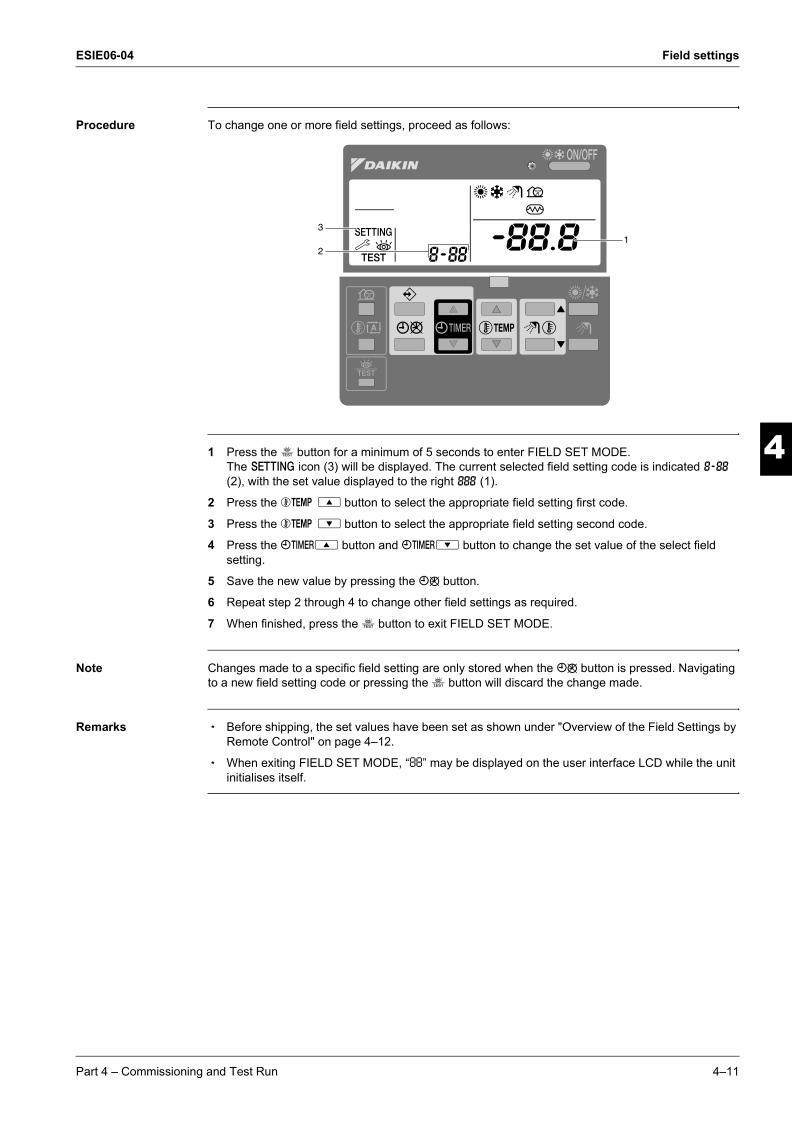
ESIE06-04 Field settings
3
4
5
1
ESIE06-04.book Page 11 Thursday, November 2, 2006 11:01 AM
Procedure To change one or more field settings, proceed as follows:
1 Press the z button for a minimum of 5 seconds to enter FIELD SET MODE.The $ icon (3) will be displayed. The current selected field setting code is indicated ; (2), with the set value displayed to the right : (1).
2 Press the bgi button to select the appropriate field setting first code.
3 Press the bgj button to select the appropriate field setting second code.
4 Press the pfi button and pfj button to change the set value of the select field setting.
5 Save the new value by pressing the pr button.
6 Repeat step 2 through 4 to change other field settings as required.
7 When finished, press the z button to exit FIELD SET MODE.
Note Changes made to a specific field setting are only stored when the pr button is pressed. Navigating to a new field setting code or pressing the z button will discard the change made.
Remarks m Before shipping, the set values have been set as shown under "Overview of the Field Settings by Remote Control" on page 4–12.
m When exiting FIELD SET MODE, “88” may be displayed on the user interface LCD while the unit initialises itself.
2
31
Part 4 – Commissioning and Test Run 4–11

Field settings ESIE06-04
3
1
4
5
ESIE06-04.book Page 12 Thursday, November 2, 2006 11:01 AM
2.3 Overview of the Field Settings by Remote Control
Overview This chapter contains the following topics:
Overview field settings
Topic See page
2.3.1–Setting [0] User Permission Level 4–13
2.3.2–Setting [1] Weather Dependent Set Point (Heating Operation only) 4–14
2.3.3–Setting [3] Auto Restart 4–15
2.3.4–Setting [9] Cooling and Heating Setpoint Limitation 4–16
First code
Second code
Setting name Default value
Range Step Unit
0 User permission level00 User permission level 3 2~3 1 —
1 Weather dependent set point00 Low ambient temperature (Lo_A) -10 -20~5 1 °C01 High ambient temperature (Hi_A) 15 10~20 1 °C02 Set point at low ambient temperature (Lo_TI) 40 25~55 1 °C03 Set point at high ambient temperature (Hi_TI) 25 25~55 1 °C
3 Auto restart00 Status 0 (ON) 0/1 — —
9 Cooling and heating set point ranges00 Heating set point upper limit 55 37~55 1 °C01 Heating set point lower limit 30 30~37 1 °C02 Cooling set point upper limit 20 18~20 1 °C03 Cooling set point lower limit 7 7~18 1 °C
4–12 Part 4 – Commissioning and Test Run

ESIE06-04 Field settings
3
4
5
1
ESIE06-04.book Page 13 Thursday, November 2, 2006 11:01 AM
2.3.1 Setting [0] User Permission Level
Outline If required, certain user interface buttons can be made unavailable for the user.
Procedure Three permission levels are defined (see the table below). Switching between level 1 and level 2/3 is done by pressing the buttons pfi and pfj immediately followed by the buttons s, ba for at least 5 seconds (in normal mode). Note that no indication on the user interface is given. When level 2/3 is selected, the actual permission level — either level 2 or level 3 — is determined by the field setting [0-00].
Overview
Button
Permission level
1 2 3Silent mode button s operable — —Weather dependent set point button ba operable — —Schedule timer enable/disable button pr operable operable —Programming button < operable — —Time adjust buttons pfi
pfj
operable — —
Inspection/test operation button z operable — —
Part 4 – Commissioning and Test Run 4–13
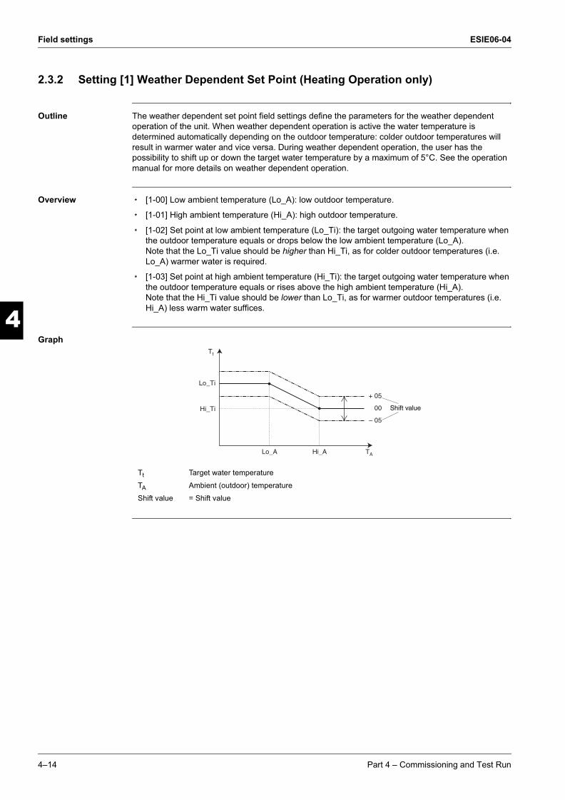
Field settings ESIE06-04
3
1
4
5
ESIE06-04.book Page 14 Thursday, November 2, 2006 11:01 AM
2.3.2 Setting [1] Weather Dependent Set Point (Heating Operation only)
Outline The weather dependent set point field settings define the parameters for the weather dependent operation of the unit. When weather dependent operation is active the water temperature is determined automatically depending on the outdoor temperature: colder outdoor temperatures will result in warmer water and vice versa. During weather dependent operation, the user has the possibility to shift up or down the target water temperature by a maximum of 5°C. See the operation manual for more details on weather dependent operation.
Overview m [1-00] Low ambient temperature (Lo_A): low outdoor temperature.
m [1-01] High ambient temperature (Hi_A): high outdoor temperature.
m [1-02] Set point at low ambient temperature (Lo_Ti): the target outgoing water temperature when the outdoor temperature equals or drops below the low ambient temperature (Lo_A). Note that the Lo_Ti value should be higher than Hi_Ti, as for colder outdoor temperatures (i.e. Lo_A) warmer water is required.
m [1-03] Set point at high ambient temperature (Hi_Ti): the target outgoing water temperature when the outdoor temperature equals or rises above the high ambient temperature (Hi_A). Note that the Hi_Ti value should be lower than Lo_Ti, as for warmer outdoor temperatures (i.e. Hi_A) less warm water suffices.
Graph
Tt Target water temperature
TA Ambient (outdoor) temperature
Shift value = Shift value
+ 05
00
– 05
Lo_Ti
Lo_A Hi_A TA
Tt
Hi_Ti Shift value
4–14 Part 4 – Commissioning and Test Run

ESIE06-04 Field settings
3
4
5
1
ESIE06-04.book Page 15 Thursday, November 2, 2006 11:01 AM
2.3.3 Setting [3] Auto Restart
Outline When power returns after a power supply failure, the auto restart function reapplies the user interface settings at the time of the power supply failure.
Overview m [3-00] Status: defines whether the auto restart function is turned on (0) or off (1).
Remark It is therefor recommended to leave the auto restart function enabled.
Note that with the function disabled the schedule timer will not be activated when power returns to the unit after a power supply failure. Press the pr button to enable the schedule timer again.
Part 4 – Commissioning and Test Run 4–15

Field settings ESIE06-04
3
1
4
5
ESIE06-04.book Page 16 Thursday, November 2, 2006 11:01 AM
2.3.4 Setting [9] Cooling and Heating Setpoint Limitation
Outline The purpose of this field setting is to prevent the user from selecting a wrong (i.e., too hot or too cold) leaving water temperature. Thereto the heating temperature set point range and the cooling temperature set point range available to the user can be configured.
Overview m [9-00] Heating set point upper limit: maximum leaving water temperature for heating operation.
m [9-01] Heating set point lower limit: minimum leaving water temperature for heating operation.
m [9-02] Cooling set point upper limit: maximum leaving water temperature for cooling operation.
m [9-03] Cooling set point lower limit: minimum leaving water temperature for cooling operation.
Remark m In case of a floor heating application, it is important to limit the maximum leaving water temperature at heating operation according to the specifications of the floor heating installation.
m In case of a floor cooling application, it is important to limit the minimum leaving water temperature at cooling operation to 16°C to prevent condensation on the floor.
4–16 Part 4 – Commissioning and Test Run

ESIE06-04 Field settings
3
4
5
1
ESIE06-04.book Page 17 Thursday, November 2, 2006 11:01 AM
2.4 Field Setting by Dip Switches from Hydro-kit
General overview
Remark Switch off the power supply before opening the switch box service panel and making any changes to the DIP switch settings.
1234OF
FO
N
Dip switch SS2 Description ON OFF
1 Not used — (Default)2 Not used — (Default)3 Not used — (Default)4 Not used — (Default)
Part 4 – Commissioning and Test Run 4–17

Field settings ESIE06-04
3
1
4
5
ESIE06-04.book Page 18 Thursday, November 2, 2006 11:01 AM
4–18 Part 4 – Commissioning and Test Run

ESIE06-04 Operation Range and Test Operation
1
ESIE06-04.book Page 19 Thursday, November 2, 2006 11:01 AM
Part 4
3
4
5
3 Operation Range and Test Operation
Introduction This chapter contains the following information:
m Operation ranges
m Test operation
m External static pressure chart
Overview This chapter contains the following topics:
Topic See page
3.1–Operation Range 4–20
3.2–Test Operation 4–21
3.3–External Static Pressure Chart 4–22
Part 4 – Commissioning and Test Run 4–19

Operation Range and Test Operation ESIE06-04
3
1
4
5
ESIE06-04.book Page 20 Thursday, November 2, 2006 11:01 AM
3.1 Operation Range
Operation range: Cooling mode
The illustration below shows the operation range: Cooling mode.
Operation range: Heating mode
The illustration below shows the operation range: Heating mode.
outdoor temp. (˚CDB)
CO
OLI
NG
MO
DE
leaving evaporatorwater temperature (˚C)
43
15
7 20
outdoor temp. (˚CDB)
HE
ATIN
G M
OD
E
leaving condensorwater temperature (˚C)
25
0
– 20
30 55
4–20 Part 4 – Commissioning and Test Run
ESIE06-04 Operation Range and Test Operation
3
4
5
1
ESIE06-04.book Page 21 Thursday, November 2, 2006 11:01 AM
3.2 Test Operation
Introduction To prevent any trouble in the period of installation at site, the system is provided with a test operation mode enabling check for incorrect wiring, stop valve left in closed, and judgment of refrigerant shortage.
Procedure 1 Push the z button 4 times so the t icon will be displayed.
2 Depending on the Hydro-kit model, heating operation, cooling operation or both must be tested as follows (when no action is performed, the user interface will return to normal mode after 10 seconds or by pressing the z button once):m To test the heating operation push the hc button so the h icon is displayed. To start the test
run operation press the o button. m To test the cooling operation push the hc button so the c icon is displayed. To start the test
run operation press the o button.
3 The test run operation will end automatically after 30 minutes or when reaching the set temperature. The test run operation can be stopped manually by pressing the z button once. If there are misconnections or malfunctions, an error code will be displayed on the user interface. Otherwise, the user interface will return to normal operation.
4 To resolve the error codes, see "Overview of Error Codes" on page 3–6.
Remarks m To display the last resolved error code, push the z button 1 time. Push the z button again 4 times to return to normal mode.
m It is not possible to test run if a forced operation from the outdoor unit is in progress. Should forced operation be started during a test run, the test run will be aborted.
Part 4 – Commissioning and Test Run 4–21

Operation Range and Test Operation ESIE06-04
3
1
4
5
ESIE06-04.book Page 22 Thursday, November 2, 2006 11:01 AM
3.3 External Static Pressure Chart
Chart The illustration below shows the External static pressure chart.
ES
P [m
H2 O
]
7
6
5
4
3
2
1
0
12 14 16 18
I II III
20 22 24
Flow [l/min]
26 28 30 32 34 36
4–22 Part 4 – Commissioning and Test Run

ESIE06-04
3
4
5
1Index
ESIE06-04.book Page i Thursday, November 2, 2006 11:01 AM
Numerics80 . . . . . . . . . . . . . . . . . . . . . . . . . . . . . . . . . . . . . . . . . .. . . . . . . . . . . . . . . . . . . . . . . . . . . . . . . . . . . . k 3–1081 . . . . . . . . . . . . . . . . . . . . . . . . . . . . . . . . . . . . . . . . . .. . . . . . . . . . . . . . . . . . . . . . . . . . . . . . . . . . . . k 3–10
AA1 . . . . . . . . . . . . . . . . . . . . . . . . . . . . . . . . . . . . . . . . . .. . . . . . . . . . . . . . . . . . . . . . . . . . . . . . . . . . . . . k 3–8A5 . . . . . . . . . . . . . . . . . . . . . . . . . . . . . . . . . . . . . . . . . .. . . . . . . . . . . . . . . . . . . . . . . . . . . . . . . . . . . . . k 3–9
CC4 . . . . . . . . . . . . . . . . . . . . . . . . . . . . . . . . . . . . . . . . . .. . . . . . . . . . . . . . . . . . . . . . . . . . . . . . . . . . . . k 3–10check
capacitor voltage ( No. 12) . . . . . . . . . . . . . . . . . . . . . . . . . . . . . . . . . . . . . . . . . . . . . . . . . . . . . k 3–60discharge pressure (No. 08) . . . . . . . . . . . . . . . . . . . . . . . . . . . . . . . . . . . . . . . . . . . . . . . . . . . . k 3–56electronic expansion valve (No. 04) . . . . . . . . . . . . . . . . . . . . . . . . . . . . . . . . . . . . . . . . . . . . . . k 3–51fan motor connector output (No. 01) . . . . . . . . . . . . . . . . . . . . . . . . . . . . . . . . . . . . . . . . . . . . . . k 3–50four way valve performance (No. 05) . . . . . . . . . . . . . . . . . . . . . . . . . . . . . . . . . . . . . . . . . . . . . k 3–52installation condition (No. 07) . . . . . . . . . . . . . . . . . . . . . . . . . . . . . . . . . . . . . . . . . . . . . . . . . . . k 3–55inverter checker ( No. 16) . . . . . . . . . . . . . . . . . . . . . . . . . . . . . . . . . . . . . . . . . . . . . . . . . . . . . . k 3–64inverter units refrigerant system ( No. 11). . . . . . . . . . . . . . . . . . . . . . . . . . . . . . . . . . . . . . . . . . k 3–59main circuit electrolytic capacitor ( No. 14) . . . . . . . . . . . . . . . . . . . . . . . . . . . . . . . . . . . . . . . . . k 3–62outdoor unit fan system check (With DC Motor) (No. 09) . . . . . . . . . . . . . . . . . . . . . . . . . . . . . . k 3–57power supply waveforms ( No. 10) . . . . . . . . . . . . . . . . . . . . . . . . . . . . . . . . . . . . . . . . . . . . . . . k 3–58power transistor ( No. 13) . . . . . . . . . . . . . . . . . . . . . . . . . . . . . . . . . . . . . . . . . . . . . . . . . . . . . . k 3–61thermistor resistance (No. 06). . . . . . . . . . . . . . . . . . . . . . . . . . . . . . . . . . . . . . . . . . . . . . . . . . . k 3–53turning speed pulse input on the outdoor unit PCB ( No. 15) . . . . . . . . . . . . . . . . . . . . . . . . . . . k 3–63
componentsfunctional diagrams . . . . . . . . . . . . . . . . . . . . . . . . . . . . . . . . . . . . . . . . . . . . . . . . . . . . . . . . . . . k 1–11PCB layout . . . . . . . . . . . . . . . . . . . . . . . . . . . . . . . . . . . . . . . . . . . . . . . . . . . . . . . . . . . . . . . . . k 1–25piping. . . . . . . . . . . . . . . . . . . . . . . . . . . . . . . . . . . . . . . . . . . . . . . . . . . . . . . . . . . . . . . . . . . . . . k 1–13switch box layout. . . . . . . . . . . . . . . . . . . . . . . . . . . . . . . . . . . . . . . . . . . . . . . . . . . . . . . . . . . . . k 1–17wired remote controller . . . . . . . . . . . . . . . . . . . . . . . . . . . . . . . . . . . . . . . . . . . . . . . . . . . . . . . . k 4–10wiring diagrams . . . . . . . . . . . . . . . . . . . . . . . . . . . . . . . . . . . . . . . . . . . . . . . . . . . . . . . . . . . . . . k 1–21
controlat mode changing . . . . . . . . . . . . . . . . . . . . . . . . . . . . . . . . . . . . . . . . . . . . . . . . . . . . . . . . . . . . k 2–16at start-up . . . . . . . . . . . . . . . . . . . . . . . . . . . . . . . . . . . . . . . . . . . . . . . . . . . . . . . . . . . . . . . . . . k 2–16defrost . . . . . . . . . . . . . . . . . . . . . . . . . . . . . . . . . . . . . . . . . . . . . . . . . . . . . . . . . . . . . . . . . . . . . . k 2–8discharge pipe temperature . . . . . . . . . . . . . . . . . . . . . . . . . . . . . . . . . . . . . . . . . . . . . . . . . . . . k 2–17electronic expansion valve . . . . . . . . . . . . . . . . . . . . . . . . . . . . . . . . . . . . . . . . . . . . . . . . . . . . . k 2–23fan . . . . . . . . . . . . . . . . . . . . . . . . . . . . . . . . . . . . . . . . . . . . . . . . . . . . . . . . . . . . . . . . . . . . . . . . k 2–20freeze-up protection . . . . . . . . . . . . . . . . . . . . . . . . . . . . . . . . . . . . . . . . . . . . . . . . . . . . . . . . . . . k 2–6frequency . . . . . . . . . . . . . . . . . . . . . . . . . . . . . . . . . . . . . . . . . . . . . . . . . . . . . . . . . . . . . . . . . . k 2–14heating peak-cut . . . . . . . . . . . . . . . . . . . . . . . . . . . . . . . . . . . . . . . . . . . . . . . . . . . . . . . . . . . . . k 2–19input current . . . . . . . . . . . . . . . . . . . . . . . . . . . . . . . . . . . . . . . . . . . . . . . . . . . . . . . . . . . . . . . . k 2–18PI control . . . . . . . . . . . . . . . . . . . . . . . . . . . . . . . . . . . . . . . . . . . . . . . . . . . . . . . . . . . . . . . . . . . k 2–15
Ddiameters, pipe connections . . . . . . . . . . . . . . . . . . . . . .. . . . . . . . . . . . . . . . . . . . . . . . . . . . . . . . . . . . k 1–12dimensions
EWA(Y)Q005~007A*V3 . . . . . . . . . . . . . . . . . . . . . . . . . . . . . . . . . . . . . . . . . . . . . . . . . . . . . . . . k 1–4
Index i

ESIE06-04
3
1
4
5
ESIE06-04.book Page ii Thursday, November 2, 2006 11:01 AM
EE1 . . . . . . . . . . . . . . . . . . . . . . . . . . . . . . . . . . . . . . . . . .. . . . . . . . . . . . . . . . . . . . . . . . . . . . . . . . . . . . k 3–12E5 . . . . . . . . . . . . . . . . . . . . . . . . . . . . . . . . . . . . . . . . . .. . . . . . . . . . . . . . . . . . . . . . . . . . . . . . . . . . . . k 3–13E6 . . . . . . . . . . . . . . . . . . . . . . . . . . . . . . . . . . . . . . . . . .. . . . . . . . . . . . . . . . . . . . . . . . . . . . . . . . . . . . k 3–15E7 . . . . . . . . . . . . . . . . . . . . . . . . . . . . . . . . . . . . . . . . . .. . . . . . . . . . . . . . . . . . . . . . . . . . . . . . . . . . . . k 3–16E8 . . . . . . . . . . . . . . . . . . . . . . . . . . . . . . . . . . . . . . . . . .. . . . . . . . . . . . . . . . . . . . . . . . . . . . . . . . . . . . k 3–17EA . . . . . . . . . . . . . . . . . . . . . . . . . . . . . . . . . . . . . . . . . .. . . . . . . . . . . . . . . . . . . . . . . . . . . . . . . . . . . . k 3–19electrical specifications . . . . . . . . . . . . . . . . . . . . . . . . . .. . . . . . . . . . . . . . . . . . . . . . . . . . . . . . . . . . . . . k 1–7error codes
hydro-box. . . . . . . . . . . . . . . . . . . . . . . . . . . . . . . . . . . . . . . . . . . . . . . . . . . . . . . . . . . . . . . . . . . . k 3–7outdoor units . . . . . . . . . . . . . . . . . . . . . . . . . . . . . . . . . . . . . . . . . . . . . . . . . . . . . . . . . . . . . . . . k 3–11overview . . . . . . . . . . . . . . . . . . . . . . . . . . . . . . . . . . . . . . . . . . . . . . . . . . . . . . . . . . . . . . . . . . . . k 3–6system malfunctions . . . . . . . . . . . . . . . . . . . . . . . . . . . . . . . . . . . . . . . . . . . . . . . . . . . . . . . . . . k 3–41
FF3. . . . . . . . . . . . . . . . . . . . . . . . . . . . . . . . . . . . . . . . . . .. . . . . . . . . . . . . . . . . . . . . . . . . . . . . . . . . . . . k 3–21F6. . . . . . . . . . . . . . . . . . . . . . . . . . . . . . . . . . . . . . . . . . .. . . . . . . . . . . . . . . . . . . . . . . . . . . . . . . . . . . . k 3–23fault-diagnosis by remote controller. . . . . . . . . . . . . . . . .. . . . . . . . . . . . . . . . . . . . . . . . . . . . . . . . . . . . . k 3–5field settings
dip switches from hydro-box . . . . . . . . . . . . . . . . . . . . . . . . . . . . . . . . . . . . . . . . . . . . . . . . . . . . k 4–17overview remote control . . . . . . . . . . . . . . . . . . . . . . . . . . . . . . . . . . . . . . . . . . . . . . . . . . . . . . . k 4–12wired remote controller . . . . . . . . . . . . . . . . . . . . . . . . . . . . . . . . . . . . . . . . . . . . . . . . . . . . . . . . k 4–10
four way valve switching . . . . . . . . . . . . . . . . . . . . . . . . .. . . . . . . . . . . . . . . . . . . . . . . . . . . . . . . . . . . . . k 2–5frequency principle. . . . . . . . . . . . . . . . . . . . . . . . . . . . . .. . . . . . . . . . . . . . . . . . . . . . . . . . . . . . . . . . . . k 2–12
HH0 . . . . . . . . . . . . . . . . . . . . . . . . . . . . . . . . . . . . . . . . . .. . . . . . . . . . . . . . . . . . . . . . . . . . . . . . . . . . . . k 3–25H6 . . . . . . . . . . . . . . . . . . . . . . . . . . . . . . . . . . . . . . . . . .. . . . . . . . . . . . . . . . . . . . . . . . . . . . . . . . . . . . k 3–27H8 . . . . . . . . . . . . . . . . . . . . . . . . . . . . . . . . . . . . . . . . . .. . . . . . . . . . . . . . . . . . . . . . . . . . . . . . . . . . . . k 3–29H9 . . . . . . . . . . . . . . . . . . . . . . . . . . . . . . . . . . . . . . . . . .. . . . . . . . . . . . . . . . . . . . . . . . . . . . . . . . . . . . k 3–31
Iinstallation space
EWA(Y)Q005~007A*V3 . . . . . . . . . . . . . . . . . . . . . . . . . . . . . . . . . . . . . . . . . . . . . . . . . . . . . . . . k 1–5
JJ3 . . . . . . . . . . . . . . . . . . . . . . . . . . . . . . . . . . . . . . . . . . .. . . . . . . . . . . . . . . . . . . . . . . . . . . . . . . . . . . . k 3–31J6 . . . . . . . . . . . . . . . . . . . . . . . . . . . . . . . . . . . . . . . . . . .. . . . . . . . . . . . . . . . . . . . . . . . . . . . . . . . . . . . k 3–31
LL3. . . . . . . . . . . . . . . . . . . . . . . . . . . . . . . . . . . . . . . . . . .. . . . . . . . . . . . . . . . . . . . . . . . . . . . . . . . . . . . k 3–33L4. . . . . . . . . . . . . . . . . . . . . . . . . . . . . . . . . . . . . . . . . . .. . . . . . . . . . . . . . . . . . . . . . . . . . . . . . . . . . . . k 3–35L5. . . . . . . . . . . . . . . . . . . . . . . . . . . . . . . . . . . . . . . . . . .. . . . . . . . . . . . . . . . . . . . . . . . . . . . . . . . . . . . k 3–37liquid compression protection function 2 . . . . . . . . . . . . .. . . . . . . . . . . . . . . . . . . . . . . . . . . . . . . . . . . . k 2–21locating
functional diagrams . . . . . . . . . . . . . . . . . . . . . . . . . . . . . . . . . . . . . . . . . . . . . . . . . . . . . . . . . . . k 1–11PCB layout. . . . . . . . . . . . . . . . . . . . . . . . . . . . . . . . . . . . . . . . . . . . . . . . . . . . . . . . . . . . . . . . . . k 1–25piping . . . . . . . . . . . . . . . . . . . . . . . . . . . . . . . . . . . . . . . . . . . . . . . . . . . . . . . . . . . . . . . . . . . . . . k 1–13switch box layout . . . . . . . . . . . . . . . . . . . . . . . . . . . . . . . . . . . . . . . . . . . . . . . . . . . . . . . . . . . . . k 1–17wired remote controller components . . . . . . . . . . . . . . . . . . . . . . . . . . . . . . . . . . . . . . . . . . . . . . k 4–10wiring diagrams . . . . . . . . . . . . . . . . . . . . . . . . . . . . . . . . . . . . . . . . . . . . . . . . . . . . . . . . . . . . . . k 1–21
low Hz high pressure limit . . . . . . . . . . . . . . . . . . . . . . . .. . . . . . . . . . . . . . . . . . . . . . . . . . . . . . . . . . . . k 2–22
ii Index

ESIE06-04
3
4
5
1
ESIE06-04.book Page iii Thursday, November 2, 2006 11:01 AM
Mmalfunctions . . . . . . . . . . . . . . . . . . . . . . . . . . . . . . . . . .. . . . . . . . . . . . . . . . . . . . . . . . . . . . . . . . . . . . k 2–27
Ooperation
forced . . . . . . . . . . . . . . . . . . . . . . . . . . . . . . . . . . . . . . . . . . . . . . . . . . . . . . . . . . . . . . . . . . . . . . k 2–9preheating . . . . . . . . . . . . . . . . . . . . . . . . . . . . . . . . . . . . . . . . . . . . . . . . . . . . . . . . . . . . . . . . . . . k 2–4range . . . . . . . . . . . . . . . . . . . . . . . . . . . . . . . . . . . . . . . . . . . . . . . . . . . . . . . . . . . . . . . . . . . . . . k 4–20test . . . . . . . . . . . . . . . . . . . . . . . . . . . . . . . . . . . . . . . . . . . . . . . . . . . . . . . . . . . . . . . . . . . . . . . k 4–21
outlookEWA(Y)Q005~007A*V3 . . . . . . . . . . . . . . . . . . . . . . . . . . . . . . . . . . . . . . . . . . . . . . . . . . . . . . . . k 1–4
PP4 . . . . . . . . . . . . . . . . . . . . . . . . . . . . . . . . . . . . . . . . . .. . . . . . . . . . . . . . . . . . . . . . . . . . . . . . . . . . . . k 3–31PCB layout . . . . . . . . . . . . . . . . . . . . . . . . . . . . . . . . . . .. . . . . . . . . . . . . . . . . . . . . . . . . . . . . . . . . . . . k 1–25PI Control . . . . . . . . . . . . . . . . . . . . . . . . . . . . . . . . . . . .. . . . . . . . . . . . . . . . . . . . . . . . . . . . . . . . . . . . k 2–15piping
EWA(Y)Q005~007A*V3 . . . . . . . . . . . . . . . . . . . . . . . . . . . . . . . . . . . . . . . . . . . . . . . . . . . . . . . k 1–14pre-test run checks . . . . . . . . . . . . . . . . . . . . . . . . . . . . .. . . . . . . . . . . . . . . . . . . . . . . . . . . . . . . . . . . . . k 4–3procedure of self-diagnosis by remote controller . . . . . .. . . . . . . . . . . . . . . . . . . . . . . . . . . . . . . . . . . . . k 3–4
Sself-diagnosis by wired remote controller . . . . . . . . . . . .. . . . . . . . . . . . . . . . . . . . . . . . . . . . . . . . . . . . . k 3–5service space
EWA(Y)Q005~007A*V3 . . . . . . . . . . . . . . . . . . . . . . . . . . . . . . . . . . . . . . . . . . . . . . . . . . . . . . . . k 1–5settings by remote control
auto restart . . . . . . . . . . . . . . . . . . . . . . . . . . . . . . . . . . . . . . . . . . . . . . . . . . . . . . . . . . . . . . . . . k 4–15cooling and heating setpoint limitation . . . . . . . . . . . . . . . . . . . . . . . . . . . . . . . . . . . . . . . . . . . . k 4–16user permission level . . . . . . . . . . . . . . . . . . . . . . . . . . . . . . . . . . . . . . . . . . . . . . . . . . . . . . . . . k 4–13weather dependent set point. . . . . . . . . . . . . . . . . . . . . . . . . . . . . . . . . . . . . . . . . . . . . . . . . . . . k 4–14
specifications. . . . . . . . . . . . . . . . . . . . . . . . . . . . . . . . . .. . . . . . . . . . . . . . . . . . . . . . . . . . . . . . . . . . . . . k 1–7switch boxes . . . . . . . . . . . . . . . . . . . . . . . . . . . . . . . . . .. . . . . . . . . . . . . . . . . . . . . . . . . . . . . . . . . . . . k 1–17
Ttechnical specifications . . . . . . . . . . . . . . . . . . . . . . . . . .. . . . . . . . . . . . . . . . . . . . . . . . . . . . . . . . . . . . . k 1–7test run checks
for water pipework. . . . . . . . . . . . . . . . . . . . . . . . . . . . . . . . . . . . . . . . . . . . . . . . . . . . . . . . . . . . . k 4–4general . . . . . . . . . . . . . . . . . . . . . . . . . . . . . . . . . . . . . . . . . . . . . . . . . . . . . . . . . . . . . . . . . . . . . k 4–7
troubleshootingadditional checks. . . . . . . . . . . . . . . . . . . . . . . . . . . . . . . . . . . . . . . . . . . . . . . . . . . . . . . . . . . . . k 3–49general . . . . . . . . . . . . . . . . . . . . . . . . . . . . . . . . . . . . . . . . . . . . . . . . . . . . . . . . . . . . . . . . . . . . . k 3–3
UU0 . . . . . . . . . . . . . . . . . . . . . . . . . . . . . . . . . . . . . . . . . .. . . . . . . . . . . . . . . . . . . . . . . . . . . . . . . . . . . . k 3–42U2 . . . . . . . . . . . . . . . . . . . . . . . . . . . . . . . . . . . . . . . . . .. . . . . . . . . . . . . . . . . . . . . . . . . . . . . . . . . . . . k 3–44U4 . . . . . . . . . . . . . . . . . . . . . . . . . . . . . . . . . . . . . . . . . .. . . . . . . . . . . . . . . . . . . . . . . . . . . . . . . . . . . . k 3–45U7 . . . . . . . . . . . . . . . . . . . . . . . . . . . . . . . . . . . . . . . . . .. . . . . . . . . . . . . . . . . . . . . . . . . . . . . . . . . . . . k 3–47
Wwiring diagrams . . . . . . . . . . . . . . . . . . . . . . . . . . . . . . . .. . . . . . . . . . . . . . . . . . . . . . . . . . . . . . . . . . . . k 1–21
Index iii

ESIE06-04
3
1
4
5
ESIE06-04.book Page iv Thursday, November 2, 2006 11:01 AM
iv Index