service & installation manual · 2017-11-07 · pool and spa/hot tub heaters h150fd, h200fd,...
TRANSCRIPT

FOR YOUR SAFETY
WARNING: If the information in these instructions is not followed exactly, a fire or explosion may result causing property damage, injury, or death.
- Do not store or use gasoline or other flam-mable vapors or liquids in the vicinity of this or any other appliance.
WHAT TO DO IF YOU SMELL GAS: • Do not try to light any appliance. • Do not touch any electrical switch; do not use
any phone in your building. • Immediately call your gas supplier from a
neighbor’s phone. Follow the gas supplier’s instructions.
• If you cannot reach your gas supplier, call the fire department.
- Installation and service must be performed by a qualified installer, service agency, or the gas supplier.
POOL AND SPA/HOT TUB HEATERSH150FD, H200FD, H250FD, H300FD,
H350FD, H400FD & H500FD MODELS
SERVICE & INSTALLATION MANUAL
FOR YOUR SAFETYThis product must be installed and serviced by authorized personnel, qualified in pool/
spa heater installation. Improper installation and/or operation can create carbon monoxide gas and flue gases that can cause serious injury, property damage, or death.
1301623301 Rev T 0117See www.hayward-pool.com/patent for U.S. andCanadian patent information

Pomona, CA Clemmons, NC Nashville, TNTel: 908-355-7995 www.hayward-pool.com
USE ONLY HAYWARD GENUINE REPLACEMENT PARTS
2 CONTENTS
Safety Information .............................................. 3
Section I General information ........................... 7 Introduction .................................................... 7 Warranty ........................................................ 7 Maintaining proper water chemistry ............... 7
Section II Installation ......................................... 9 Equipment inspection .................................... 9 Important notice ............................................. 9 Conformance with codes ............................... 9 Altitude of installation ..................................... 9 Uncrating the heater .................................... 11 Locating the heater ....................................... 11 Flooring ........................................................ 13 Tie-Down Brackets ....................................... 13 Indoor Installation and Venting ..................... 14 Clearances ................................................... 14 Air Supply ..................................................... 14 Vertical Venting ............................................. 16 Horizontal or Vertical Venting ....................... 17 Reversible water connections ...................... 19 Gas supply and piping ................................. 21 Water piping ................................................. 24 Installation above pool surface .................... 26 Chlorinator/chemical feeder ......................... 26 Drain valve installation (ASME Models) ....... 27 Pressure relief valve .................................... 27 Electricalspecifications ................................ 27 Electrical connections .................................. 28 Remote control connection .......................... 29
Section III Check-out & Start-up ..................... 32 General ........................................................ 32 Gas line testing ............................................ 33 Gas pressure testing ................................... 33 Water pressure switch ................................. 35 Two-speed pump ......................................... 35 Temperature adjustment .............................. 36 Temperature lock-out ................................... 37 Fahrenheit v. Celsius ................................... 37 Heating mode .............................................. 37 Retry (Failure of light) .................................. 38 Recycle(Lossofflame) ............................... 38 Keypad inputs .............................................. 38 Automatic reset time .................................... 39 Periodic inspection ...................................... 39 Winterization ................................................ 39 Draining the heat exchanger ....................... 40 Spring start-up ............................................. 40
Section IV Technician Service ........................ 41 General ........................................................ 41 Maintenance ................................................ 41 Heat exchanger inspection and cleaning ..... 41 Combustion chamber .................................. 42 Burner inspection and cleaning ................... 42 Burner removal and replacement ................ 42 Gas valve replacement ................................ 43 Igniter ........................................................... 43 Flame sensor ............................................... 44 Burnerorifices ............................................. 44 Gas conversion ............................................ 44 Electrical wiring ............................................ 44 Ignition control system ................................. 44 Blower vacuum switch .................................. 45 High limit switch ........................................... 45 Thermistor .................................................... 46 Water pressure switch ................................. 47 Transformer ................................................. 47 Blower .......................................................... 48 By-pass service cartridge ............................ 48
Section V Troubleshooting ............................. 49 General ........................................................ 49 Automatic reset time .................................... 49 Supply wiring ............................................... 49 Internal wiring .............................................. 49 Fusespecifications ...................................... 50 Error codes ................................................... 51 Troubleshooting ........................................... 53 Warranty ....................................................... 59 Service Parts ................................................ 61

Pomona, CA Clemmons, NC Nashville, TNTel: 908-355-7995 www.hayward-pool.com
USE ONLY HAYWARD GENUINE REPLACEMENT PARTS
3SAFETy INFORMATION
Basic safety precautions should always be followed, including the following: Failure to follow instructions can cause severe injury and/or death.
This is the safety-alert symbol. When you see this symbol on your equipment or in this manual, look for one of the following signal words and be alert to the potential for personal injury.
WARNING warns about hazards that could cause serious personal injury, death or major property damage and if ignored presents a potential hazard.
CAUTION warns about hazards that will or can cause minor or moderate personal injury and/or property damage and if ignored presents a potential hazard. It can also make consumers aware of actions that are unpredictable and unsafe.
ATTENTION indicates special instructions that are important but not related to hazards.
READ AND FOLLOW ALL INSTRUCTIONS IN THIS OWNER’SMANUAL AND ON EQUIPMENT.
IMPORTANT SAFETy INSTRUCTIONSBefore installing or servicing this electrical equipment, turn power supply OFF.
KEEP SAFETy LABELS IN GOOD CONDITION AND REPLACE IF MISSING OR DAMAGED.
WARNING – To reduce risk of injury, do not permit children to use or climb on the heater, pumps or filters. Closely supervise children at all times. Components such as the filtration system, pumps, and heaters must be positioned to prevent children from using them as a means of access to the pool.
CAUTION – This heater is intended for use on permanently installed swimming pools and may also be used with spas. Do NOT use with storable pools. A permanently installed pool is constructed in or on the ground or in a building such that it cannot be readily disassembled for storage. A storable pool is constructed so that it is capable of being readily disassembled for storage and reassembled to its origi-nal integrity.
Though this product is designed for outdoor use, it is strongly recommended to protect the electrical components from the weather. Select a well drained area, one that will not flood when it rains. It requires free circulation of air for cooling. Do not install in a damp or non-ventilated location.
WARNING – It is required that licensed electricians do all electrical wiring. Risk of Electric Shock. Hazardous voltage can shock, burn, cause death or serious property damage. To reduce the risk of electric shock, do NOT use an extension cord to connect unit to electric supply. Provide a properly located outlet. All electrical wiring MUST be in conformance with applicable local and national codes and regulations. Before work-ing on this unit, turn off power supply to the heater.
WARNING – To reduce the risk of electric shock replace damaged wiring immediately. Locate conduit to prevent abuse from lawn mowers, hedge trimmers and other equipment.
WARNING – Failure to bond to pool structure will increase risk for electrocution and could result in injury or death. To reduce the risk of electric shock, the electrician must comply with installation instructions and must bond the heater accordingly. In addition, the licensed electrician must also con-form to local electrical codes for bonding requirements.

Pomona, CA Clemmons, NC Nashville, TNTel: 908-355-7995 www.hayward-pool.com
USE ONLY HAYWARD GENUINE REPLACEMENT PARTS
4
NOTES TO THE ELECTRICIAN:Use a solid copper conductor, size 8 or larger. Run a continuous wire from external bonding lug to rein-
forcing rod or mesh. Connect a No. 8 AWG solid copper bonding wire to the grounding lug provided on the heater and to all metal parts of swimming pool or spa, and to all electrical equipment, metal piping (except gas piping), and conduit within 5 ft. (1.5 m) of inside walls of swimming pool or spa. IMPORTANT -Refer-ence NEC codes for all wiring standards including, but not limited to, grounding, bonding and other general wiring procedures.
WARNING – Suction Entrapment Hazard.Suction in suction outlets and/or suction outlet covers which are damaged, broken, cracked, missing, or unsecured can cause severe injury and/or death due to the following entrapment hazards:
Hair Entrapment- Hair can become entangled in suction outlets.
Limb Entrapment- A limb inserted into an opening of a suction outlet or suction outlet cover that is damaged, broken, cracked, missing, or not securely attached can result in a mechanical bind or swelling of the limb.
Body Suction Entrapment- A differential pressure applied to a large portion of the body or limbs can result in an entrapment.
Evisceration/ Disembowelment - A vacuum applied directly to the intestines through an unprotected suction outlet sump or suction outlet cover which is damaged, broken, cracked, missing, or unsecured can result in evisceration (disembowelment).
Mechanical Entrapment- There is potential for jewelry, swimsuit, hair decorations, finger, toe or knuck-le to be caught in an opening of a suction outlet or suction outlet cover resulting in mechanical entrap-ment.
WARNING - To reduce the risk of entrapment hazards:• When suction outlets are less than a 18” x 23” equivalent, a minimum of two
functioning suction outlets per pump must be installed. Suction outlets in the same plane (i.e. floor or wall), must be installed a minimum of three feet (3’) [1 meter] apart, as measured from near point to near point.
• Dual suction outlets shall be placed in such locations and distances to avoid “dual blockage” by a user.
• Dual suction fittings shall not be located on seating areas or on the backrest for such seating areas.
• The maximum system flow rate shall not exceed the flow rating of any listed (per current revision of ASME/ANSI A112.19.8) suction outlet cover installed.
• Never use the Pool or Spa if any suction outlet component is damaged, broken, cracked, missing, or not securely attached.
• Replace damaged, broken, cracked, missing, or not securely attached suction outlet components imme-diately.
• Install two or more suction outlets per pump in accordance with latest APSP (formally NSPI) Standards and CPSC guidelines. Follow all applicable National, State, and Local codes.

Pomona, CA Clemmons, NC Nashville, TNTel: 908-355-7995 www.hayward-pool.com
USE ONLY HAYWARD GENUINE REPLACEMENT PARTS
5
WARNING – Failure to remove pressure test plugs and/or plugs used in winterization of the pool/spa from the suction outlets can result in an increase potential for suction entrapment as described above.
WARNING – Failure to keep suction outlet components clear of debris, such as leaves, dirt, hair, paper and other material can result in an increase potential for suction entrapment as described above.
WARNING – Suction outlet components have a finite life, the cover/grate should be inspected fre-quently and replaced at least every ten years or if found to be damaged, broken, cracked, missing, or not securely attached.
WARNING – All suction and discharge valves MUST be OPEN when starting the circulation system. Failure to do so could result in severe personal injury and/or property damage. All drains and suction outlets MUST have properly installed covers, securely attached using the screws supplied with the covers. If screws are lost, order replacement parts from your supplier.
WARNING – Hazardous Pressure. Pool and spa water circulation systems operate under hazardous pressure during start up, normal operation, and after pump shut off. Stand clear of circulation system equipment during start up. Fail-ure to follow safety and operation instructions could result in violent separation of the pump housing and cover due to pressure in the system, which could cause property damage, severe personal injury, or death. Before servicing pool and spa water circulation system, all system and pump controls must be in off position and filter manual air relief valve must be in open position. Before starting system pump, all system valves must be set in a position to allow system water to return back to the pool. Do not change filter control valve position while system pump is running. Before starting system pump, fully open filter manual air relief valve. Do not close filter manual air relief valve until a steady stream of water (not air or air and water) is discharged.
WARNING – Separation Hazard. Failure to follow safety and operation in-structions could result in violent separation of pump components. Strainer cover must be properly secured to pump housing with strainer cover lock ring. Before servicing pool and spa circulation system, manual air relief valve must be in open position. Do not operate pool and spa circulation system if a system component is not assembled properly, damaged, or missing. Do not operate pool and spa circu-lation system unless filter air relief valve body is in locked position in filter upper body.
WARNING – Never operate or test the circulation system at more than 40 PSI.
WARNING – Fire and burn hazard. Motors operate at high temperatures and if they are not properly isolated from any flammable structures or foreign debris they can cause fires, which may cause severe personal injury or death. It is also necessary to allow the motor to cool for at least 20 minutes prior to maintenance to minimize the risk of burns.
WARNING – Failure to install according to defined instructions may result in severe personal injury or death.

Pomona, CA Clemmons, NC Nashville, TNTel: 908-355-7995 www.hayward-pool.com
USE ONLY HAYWARD GENUINE REPLACEMENT PARTS
6
WARNING – The following “Safety Rules for Hot Tubs” recommended by the U.S. Consumer Product Safety Commission should be observed when using the spa.
1. Spa or hot tub water temperatures should never exceed 104°F [40°C]. A temperature of 100°F [38°C] is considered safe for a healthy adult. Special caution is suggested for young children. Prolonged im-mersion in hot water can induce hyperthermia.
2. Drinking of alcoholic beverages before or during spa or hot tub use can cause drowsiness, which could lead to unconsciousness and subsequently result in drowning.
3. Pregnant women beware! Soaking in water above 100°F [38°C] can cause fetal damage during the first three months of pregnancy (resulting in the birth of a brain-damaged or deformed child). Pregnant women should adhere to the 100°F [38°C] maximum rule.
4. Before entering the spa or hot tub, users should check the water temperature with an accurate ther-mometer; spa or hot tub thermostats may err in regulating water temperatures by as much as 4°F (2.2°C).
5. Persons taking medications, which induce drowsiness, such as tranquilizers, antihistamines or antico-agulants, should not use spas or hot tubs.
6. If the pool/spa is used for therapy, it should be done with the advice of a physician. Always stir pool/spa water before entering the pool/spa to mix in any hot surface layer of water that might exceed healthful temperature limits and cause injury. Do not tamper with controls, because scalding can result if safety controls are not in proper working order.
7. Persons with a medical history of heart disease, circulatory problems, diabetes or blood pressure prob-lems should obtain a physicians advice before using spas or hot tubs.
8. Hyperthermia occurs when the internal temperature of the body reaches a level several degrees above normal body temperature of 98.6°F [37°C]. The symptoms of Hyperthermia include: drowsiness, leth-argy, dizziness, fainting, and an increase in the internal temperature of the body.
The effects of Hyperthermia include:1. Unawareness of impending danger.2. Failure to perceive heat.3. Failure to recognize the need to leave the spa.4. Physical inability to exit the spa.5. Fetal damage in pregnant women.6. Unconsciousness resulting in danger of drowning.
DEFINITIONS:Suction Outlet – The term Suction Outlet is a fitting, fitting assembly, cover/grate and related
components that provide a means for water to exit the pool and into the pump circulating system.
Inches of Mercury (in Hg) - A unit for measuring pressure below atmospheric (“suction” or “vacuum”) (1.0 inch Hg = .491 PSI)
Main Drain – See Suction Outlet
PSI – An abbreviation for pounds per square inch.

Pomona, CA Clemmons, NC Nashville, TNTel: 908-355-7995 www.hayward-pool.com
USE ONLY HAYWARD GENUINE REPLACEMENT PARTS
7
INTRODUCTION:This manual contains instructions for installation, operation, maintenance, troubleshooting, and parts lists
for the safe use of the swimming pool/spa/hot tub heaters. Hayward strongly recommends that the installer read the manual before installing the swimming pool/spa/hot tub heater. If after reviewing the manual any questions remain unanswered, contact the factory or local representative. Following heater installation, the installer should leave all manuals with the consumer for future reference.
LIMITED WARRANTy SUMMARy:Hayward warrants the pool/spa/hot tub heater to be free from defects in materials and workmanship, and
will within one year from date of installation for all users, for the original purchaser, repair or, at our option, replace without charge any defective part. Hayward further warrant that if the heat exchanger or exchanger headers (water-containing section) leak within one year from date of such installation for all users, due to defects in materials and workmanship, Hayward will provide a replacement part. Cost of freight, installation, fuel, and service labor (after one year) is at user’s expense. For full details of warranty agreement, see war-ranty certificate included in this manual.
ATTENTION: If the pool/spa/hot tub heater is damaged or destroyed by improper maintenance, exces-sive water hardness, incorrect water chemistry, or freezing it is not covered under the manufacturer’s warranty.
MAINTAINING PROPER WATER CHEMISTRy:
WARNING: Failure to maintain proper water chemistry may cause premature heat exchanger damage or failure.
The heat exchanger in your Hayward pool heater is made from the highest quality of copper and nickel (Cupronickel) materials. The premium materials and the exacting processes used in the manufacture of the heat exchanger is state of the art in pool heater design and manufacture. Yet, it remains vital that the heat ex-changer be protected from damaging or corrosive chemicals, insufficient water flow or improperly balanced water chemistry. Heat exchanger damage or failure resulting from improper flow, improperly balanced pool water or the improper addition of sanitizer into the water is NOT covered under the terms of your warranty.
The following factors are critical to heat exchanger protection. Follow these guidelines to help prevent pre-mature damage or failure to your heater and heat exchanger.
1. WATER FLOW THROUGH HEATER Water must be flowing through the heater at the minimum rated flow rate during operation. Check that the pump is operating and the system is filled with water and purged of all air prior to starting the heater. The minimum rated flow rates are listed on page 25. Some installations may require an adjustment to the water pressure switch for proper low-flow protection. Test your system and if necessary, adjust the water pressure switch as described on page 35.
SECTION I. GENERAL INFORMATION

Pomona, CA Clemmons, NC Nashville, TNTel: 908-355-7995 www.hayward-pool.com
USE ONLY HAYWARD GENUINE REPLACEMENT PARTS
8
2. POOL/SPA WATER CHEMISTRy The chemistry balance and mineral content of swimming pool water changes daily due to the addition of pool and sanitizing chemicals, bather loads, rain, runoff and the amount of sun - to name a few. Improper chem-istry balance and mineral content can cause scaling and deposits to form on pool walls, in the filtration system, in the heat exchanger tubes and additionally can promote corrosive action to all metals in the water path. Chang-ing spa water regularly and maintaining the correct chemical balance in your pool/spa will keep the pool/spa safe and sanitary, and will help protect the heat exchanger. Use a 4-way pool/spa water test kit to check your water frequently (at least weekly). Use the following guidelines to help protect your heater’s heat exchanger:
3. SKIMMER CHLORINATION Placing chlorine or bromine tablets directly into the skimmer may result in high chemical concentrations flowing through the heater. DO NOT place chlorine or bromine tablets in the skimmer.
4. CHLORINATOR INSTALLATION Chlorinators must be installed downstream of the heater, and a check valve must be installed between the heater and chlorinator to prevent high chemical concentrations from back flowing into the heater. Make sure your piping arrangement meets the chlorinator installation requirements shown on page 26.
5. ByPASS Until water chemistry is properly balanced, and if your piping has a bypass valve installed for the heater, open the bypass so that corrosive and potentially damaging water will not flow through the heater and there-fore the heat exchanger. Close the bypass valve once the water is properly balanced. Failure to close the bypass valve when attempting to operate the heater will result in extensive damage to the heat exchanger. Ensure water flow through the heater is restored before operating the heater. A bypass feature is also advanta-geous for service needs and for the ability to remove the heater from the water path when not heating. Refer to page 25 for further information.
Recommended Level Effect of Low Levels Effect of High Levels
Chlorine 1 - 3 ppmBromine 2 - 4 ppm
pH 7.4 - 7.6 corrosive to heat exchanger, swimmer irritation
cloudy water, scaling of heat exchanger, reduced sanitizer effectiveness
Total Alkalinity 80 - 120 ppm corrosive to heat exchanger, large fluctuations in pH scaling of heat exchanger
Calcium Hardness 200 - 400 ppm corrosive to heat exchanger scaling of heat exchanger
Salt 2700 - 5000 ppm poor salt chlorinator performance corrosive to heat exchanger
hazy water, algea growth, bacteria causing infections
swimmer irritation, bleaching of clothes/hair, corrosive to heat exchanger

Pomona, CA Clemmons, NC Nashville, TNTel: 908-355-7995 www.hayward-pool.com
USE ONLY HAYWARD GENUINE REPLACEMENT PARTS
9
EQUIPMENT INSPECTION:On receipt of the heater, inspect the heater carton(s) for damage. If any carton(s) is damaged, note it when
signing for it. Remove the heater from the carton(s) inspect it and advise the carrier of any damages at once.
IMPORTANT NOTICE:The installation instructions are intended for the use of a qualified technician, specifically trained and
experienced in the installation of this type of heating equipment. Some states or provinces require that instal-lation be licensed. If this is the case in the state or province where heater is located, the contractor must be properly licensed.
WARNING: Failure to comply with the appliance and vent package installation instructions and service instructions in this manual may result in equipment damage, fire, asphyxiation, or carbon monoxide poisoning. Exposure to products of incomplete combustion (carbon monoxide) can cause cancer and birth defects or other reproductive harm.
CONFORMANCE WITH CODES:The heater shall be installed in accordance with all local and state codes. The heater installation must con-
form to the latest edition of the National Fuel Gas Code (ANSI Z223.1/NFPA 54) and with the requirements of the authority having jurisdiction. Design certification of the heater is in compliance with ANSI Z21.56/CSA 4.7.
For Canadian installations, the heater is to be installed in accordance with the standards CAN/CGA B149.1 and B149.2 – Installation Codes for Gas Burning Appliances and Equipment and/or local codes and, if appli-cable, CSA C22.1 – Canadian Electrical Code, Part I.
ALTITUDE OF INSTALLATION:Heaters may be installed at any altitude up to 10,100 ft above sea level, provided the appropriate
modification(s) are performed. The altitudes which require modification vary depending on the model. Parts necessary to convert the heater for outdoor installation at altitudes up to 7,700 ft (minimum) are included with the heater. Conversion is accomplished by replacement of the blower air inlet plate, and for indoor ap-plications, installation of the appropriate vent pressure switch. The blower air inlet plates are clearly marked with the compatible heater model(s), vent configuration(s), and altitude range(s). Care should be taken to verify the correct plate and vent pressure switch is being used to ensure proper heater performance. The vent pressure switch should be provided with the indoor adapter kit, or if you have an older indoor adapter kit, order p/n FDXLVPS1931 for the high-altitude indoor vent pressure switch.
High-Altitude Conversion Procedure:1. Identify the altitude of the installation site. This may be done using a GPS device, or by looking up the
altitude for the geographic location. Altitudes for all locations in the United States and Canada may be found using the zip/postal code database at www.zip-codes.com. If the altitude for the installation site is greater than 10,100 ft, the heater may not be installed. Note that if installing outdoors, some Universal H-Series heaters may be compatible with your altitude without modification. Table 1 lists the altitude ranges for heaters without modification. All indoor heaters installed above 2,000 ft require a special vent pressure switch.
2. Select the appropriate blower air inlet plate to use based on the heater model, vent configuration (outdoor or indoor), and altitude needed. Extra plate(s) are included with the heater, packaged in the plastic bag with this manual. Each plate has a label which identifies which model(s), vent configuration(s), and altitude range(s) for which it is designed. Table 1 lists the maximum installation altitudes using the included conversion plate(s). If installing above 7,700 ft, the high-altitude kit
SECTION II. INSTALLATION

Pomona, CA Clemmons, NC Nashville, TNTel: 908-355-7995 www.hayward-pool.com
USE ONLY HAYWARD GENUINE REPLACEMENT PARTS
10
FDXLHAK1930 (sold separately) may be necessary.3. If installing indoors, select the appropriate high-altitude indoor vent pressure switch from the indoor
adapter kit or from the FDXLVPS1931 kit. Each switch has a label which identifies which model(s) and altitude range(s) for which it is designed.
4. If connected, turn pump, main gas valve, and heater power off.5. Remove heater front access door.6. Remove the 4 #10 hex head screws that fasten the blower air inlet plate to the blower, and remove the
blower air plate and discard. Save the 4 screws as they will be needed to install the new plate. See Figure 26 (page 47).
7. Install the appropriate blower plate from the kit using the 4 screws. It may be helpful to drive the screws in and out of the plate outside of the heater first to “thread” the holes before installing it in the heater.
8. If the installation is configured for indoor venting, a special high-altitude vent pressure switch must be installed. Follow the instructions for vent kit installation (page 17), but use the appropriate blower air
inlet plate and vent pressure switch for your altitude.9. Re-install heater front door.10. If connected, turn pump, main gas valve, and heater power back on.11. Activate heater and check for proper function.
Table 1 lists the maximum altitudes for which each model is designed with: a) no modifications, b) the included conversion plate installed, and c) the accessory conversion kit FDXLHAK1930 installed (sold sepa-rately).
TABLE 1
Heater Model Gas
Maximum Installation AltitudeOutdoor Installation Indoor Installation *
No Modifica-tions to Heater
Included Con-version Plate Installed on
Heater
Conversion kit FDXLHAK1930
Installed on Heater
No Modifica-tions to Heater
Included Con-version Plate Installed on
Heater
Conversion kit FDXLHAK1930
Installed on Heater
H150FDN NAT 7,700 ft N/A 10,100 ft 10,100 ft N/A N/A
H150FDP LP 7,700 ft N/A 10,100 ft 2,000 ft 10,100 ft N/A
H200FDN NAT 10,100 ft N/A N/A 10,100 ft N/A N/A
H200FDP LP 5,400 ft 10,100 ft N/A 2,000 ft 10,100 ft N/A
H250FDN NAT 5,400 ft 10,100 ft N/A 2,000 ft 10,100 ft N/A
H250FDP LP 2,000 ft 7,700 ft 10,100 ft 2,000 ft 7,700 ft 10,100 ft
H300FDN NAT 10,1001 ft N/A N/A 10,100 ft N/A N/A
H300FDP LP 2,000 ft 10,100 ft N/A 2,000 ft 10,100 ft N/A
H350FDN NAT 2,000 ft 10,100 ft N/A 2,000 ft 10,100 ft N/A
H350FDP LP 2,000 ft 7,700 ft 10,100 ft 2,000 ft 7,700 ft 10,100 ft
H400FDN NAT 10,100 ft N/A N/A 10,100 ft N/A N/A
H400FDP LP 2,000 ft 7,700 ft 10,100 ft 2,000 ft 7,700 ft 10,100 ft
H500FDN NAT 10,100 ft N/A N/A 10,100 ft N/A N/A
H500FDP LP 5,400 ft 7,700 ft 10,100 ft 5,400 ft 7,700 ft 10,100 ft
* All indoor installations at altitudes above 2,000 ft require a vent pressure switch to be installed in addition to the blower inlet plate. The vent pressure switch is included with the appropriate indoor vent kit (UHXNEGVT1xxx or UHX-POSHZ1xxxx), or the high-altitude vent pressure switch kit FDXLVPS1931.

Pomona, CA Clemmons, NC Nashville, TNTel: 908-355-7995 www.hayward-pool.com
USE ONLY HAYWARD GENUINE REPLACEMENT PARTS
11
LOCATING THE HEATER:Locate the pool/spa/hot tub heater in an area where leakage of the heat exchanger or connections will not
result in damage to the area adjacent to the heater or to the structure. When such locations cannot be avoided, it is recommended that a suitable drain pan, with drain outlet, be installed under the heater. The pan must not restrict airflow.
This heater must be installed at least (5) feet from the inside wall of a pool (in-ground or above-ground)/ spa/hot tub unless separated from the pool/spa/hot tub by a solid barrier.
The heater must be installed such that the location of the exhaust gas vent assembly outlet relative to adjacent public walkways, adjacent buildings, openable windows, and building openings complies with the National Fuel Gas Code (ANSI Z223.1/NFPA 54) and/or CAN/CGA B149 installation codes. Outdoor instal-lation and service clearances:
The heater must be installed outdoors such that the installation and service clearances from combustible materials shown in Table 2 are maintained. This heater may be installed on combustible floors.
1. The heater is self-venting when installed outdoors and does not require additional vent piping.2. Do not install in a location where growing shrubs may in time obstruct a heater’s combustion air and
venting areas.3. Do not install this appliance under an overhang less than (3) feet from the top of the appliance. The
area under the overhang must be open on (3) sides.4. Do not install the heater where water spray from ground sprinkler can contact the heater. The water
could splash on the controls causing electrical damage.5. Do not install under a deck.
Figure 2: Shipping Screws Inside Front Access Panel
Remove the (2) shipping screws and discard bottom corrugated tray.
The screw through the rear shipping bracket is located in this area. Remove the screw.
It is not necessary to remove the bracket or the rear louvered panel.
Figure 1: Pallet Mounting Bracket LocationUNCRATING THE HEATER:To remove the shipping carton from the heater:1. Remove the corrugated carton from the
heater. The carton, top pad, bottom pad, and the four corner posts can be recycled.
2. There are three (3) screws total used to secure the heater to the wood pallet. All three must be removed to separate the heater from the pallet. One (1) is located in the lower rear of the heater as shown in Figure 1.
3. To access the other two (2) screws, open the front access panel by remov-ing the black phillips-head screw. Then remove the two (2) screws which hold the heater base pan to the pallet as shown in Figure 2.
4. Lift the heater clear of the corrugat-ed bottom pad and off of the pallet.
ATTENTION: Do not drop the heater from a pickup truck tailgate to the ground. This may damage the heater.

Pomona, CA Clemmons, NC Nashville, TNTel: 908-355-7995 www.hayward-pool.com
USE ONLY HAYWARD GENUINE REPLACEMENT PARTS
12
Table 2Outdoor Installation Clearances
Heater Panel Required ClearanceTop Unobstructed
Front 18 inchesBack 6 inches
Water Connection Side 12 inchesSide Opposite Water Connec-
tion 6 inches
6. Do not install within 24” of any outdoor HVAC equipment.
7. Do not install where water may run-off a roof into the heater. A gutter may be need-ed to protect the heater.
8. Any enclosure around the heater must provide a combustion air vent commenc-ing within 12 inches of the bottom of the enclosure. The vent opening shall have a minimum free area of 1 square inch per 4,000 Btu/hr input rating of all gas appli-ances in the enclosure. See Table 5.
9. If the heater is to be installed in front of an exterior wall with vinyl siding, increase the clearance from the back of the unit shown in Table 2 to 12 inches.
10. For minimum exhaust vent clearances for all building openings, including but not limited to vented eaves, doors, windows, or gravity inlets, see Figure 3. In Canada, the heater must be installed with the top of the vent at least 10 feet (3m) below, or to either side of, any opening into a building.
4 ft Minimum
4 ft Minimum
3 ft Minimum
10 ft Minimum
4 ft Minimum
Figure 3: Minimum Clearances
Forced Air Inlet

Pomona, CA Clemmons, NC Nashville, TNTel: 908-355-7995 www.hayward-pool.com
USE ONLY HAYWARD GENUINE REPLACEMENT PARTS
13
FLOORING:This heater may be installed on either non-combustible or combustible flooring. Ultralite™ or equiva-
lent concrete-over-foam HVAC pads are acceptable.
TIE-DOWN BRACKETS:The heater is equipped for installation of factory-supplied tie-down brackets if required by local
codes. The brackets are shipped in the consumer kit. You will need the following to complete the installa-tion:
1. Tie-down brackets (FACTORy-SUPPLIED, quantity = 4)2. Sheet metal screws (FACTORy-SUPPLIED, quantity = 4)3. Concrete tapping screws (Tapcons®) (field-supplied, stainless steel, quantity = 4, size to be ¼”
diameter with a minimum length of 1-1/2”)4. Fender washers (field supplied, stainless steel, quantity = 4, size to be 1-1/2”)
INSTALLING TIE-DOWN BRACKETS:1. Locate the tie-down brackets and the sheet metal screws.2. Obtain the Tapcons®. Be sure the overall
length of the concrete tapping screw is at least 1-1/2”.
3. Remove the front access panel (1 screw).4. Remove the rear access panel (4 screws).5. Position the heater on the pad so that all
Tapcons® can “bite” into the pad. Observe local codes regarding pad construction, some jurisdictions specify a minimum thickness for concrete pads.
6. Slip the tie-down brackets into the slots in the front of the heater base pan from under-side of the heater, so that they are positioned as shown in Figure 4. Install the sheet metal screws through the holes in the bracket to secure the bracket to the heater base pan.
7. Install the Tapcons® through the inner set of holes in the tie-down brackets into the pad.
8. Repeat Steps 6 & 7 at the rear of the heater.9. Installation is completed when (4) brackets
are secured to the heater and the pad. Install the access panels when complete.
Equipment pad
Install sheet metal screws (supplied) at these locations (front and rear)
Install concrete tapping screws and washers (field-supplied) at these locations (front and rear)
Figure 4: Hurricane Tie-Down Installation
Use 2nd holefor Tie DownBrackets with2 Holes

14
INDOOR INSTALLATION AND VENTING:
POSITIVE AND NEGATIVE PRESSURE VENTING SySTEMSThe heater is designed such that it may be vented using either a negative-pressure or a positive-pressure
venting system. The appropriate system of venting for a particular site will depend on many factors such as vent termination needs (horizontal/vertical), and the cost of venting system. Table 3 lists the indoor vent-ing kits available and the limitations of each system. Multiple forced- or induced-draft units should never be vented using common venting or vent terminations. Never common vent this heater with other gas-burning appliances.
Table 3Indoor Vent Kits and Limitations of Venting Systems
Indoor Vent Kit Part Number Description
For Use With Heater Models
Vent Pipe Limitations Vent Pipe Material
Vent Termination Requirement
UHXNEGVT11501
Indoor Vent Adapter Kit, Negative Pressure, Vertical Venting Applications
H150FD50 ft max vertical height, 25 ft max horizontal length (horizontal length cannot exceed 1/2 of vertical height), 3 elbows max
Single or Double Wall Galvanized Non-Sealed Vent Pipe
Vertical Only, Termination Above Roof of House/Building
UHXNEGVT12001 H200FD
UHXNEGVT12501 H250FD
UHXNEGVT13001 H300FD
UHXNEGVT13501 H350FD
UHXNEGVT14001 H400FD
UHXNEGVT15001 H500FD
UHXPOSHZ11501
Indoor Vent Adapter Kit, Positive Pressure, Horizontal or Vertical Venting Applications
H150FD
50 ft max with 1 elbow, 40 ft max with 2 elbows, or 30 ft max with 3 elbows (horizontal or vertical)
Single or Double Wall Stainless Steel Sealed Vent Pipe
Horizontal or Vertical, Termina-tion Immediately Outside Wall of House/Building
UHXPOSHZ12001 H200FD
UHXPOSHZ12501UHXPOSHZ12502
H250FD
UHXPOSHZ13001 H300FD
UHXPOSHZ13501 H350FD
UHXPOSHZ14001UHXPOSHZ14002
H400FD
UHXPOSHZ15002 H500FD
CLEARANCES:The heater must be installed such that the installation and
service clearances from combustible materials shown in Table 4 are maintained. This heater may be installed on combustible floors. Do not install heater in a closet.AIR SUPPLy:
Indoor installations and outdoor shelters (confined spaces) must be provided with adequate combustion and ventilation air vents to assure proper heater operation. These vents must be sized according to the requirements stated in paragraph A or B below (whichever applies to the installation). These vents must never be obstructed when heater is in operation.
When air blowers are used in spa/hot tub installations and are located in proximity to the heater, caution must be observed to ensure sufficient combustion air is available to the heater for proper combustion. A separate blower air duct is recommended.
Table 4Indoor Installation Clearances
Heater Panel Required ClearanceTop 36 inches
Front 18 inchesBack 6 inches
Water Connection Side 12 inchesSide Opposite Water
Connection6 inches

Pomona, CA Clemmons, NC Nashville, TNTel: 908-355-7995 www.hayward-pool.com
USE ONLY HAYWARD GENUINE REPLACEMENT PARTS
15
(A) ALL AIR SUPPLy FROM INSIDE THE BUILDING:The confined space shall be provided with 2 permanent openings communicating directly with an addi-
tional room(s) of sufficient volume so that the combined volume of all spaces meets the criteria for an uncon-fined space (a space whose volume is not less than 50 cubic feet per 1,000 btu/hr). The total input of all gas utilization equipment installed in the combined space shall be considered in making the determination. Each opening shall have a minimum free area of 1 square inch per 1,000 btu/hr of the total input rating of all gas utilization equipment in the confined space, but not less than 100 square inches. See Table 5. One opening shall be within 12 inches of the top and and one within 12 inches of the bottom of the enclosure.
(B) ALL AIR SUPPLy FROM OUTDOORS:The confined space shall be provided with 2 permanent
openings, one commencing within 12 inches of the bot-tom and one commencing within 12 inches of the top of the enclosure. The opening shall communicate directly, or by ducts, with the outdoors or spaces (crawl or attic) that freely communicate with the outdoors.1. When communicating with the outdoors (either directly
or through vertical ducts), each opening shall have a minimum free area of 1 square inch per 4,000 btu/hr of total input rating of all equipment in the enclosure. See Table 5. When installing a heater below ground (in a pit), combustion and ventilation air openings must be provided as shown in Figure 5.
2. When communicating with the outdoors through hori-zontal ducts, each opening shall have a minimum free area of 1 square inch per 2,000 btu/hr of total input rat-ing of all equipment in the enclosure. See Table 5.
3. When ducts are used, they shall be of the same cross-sectional area as the free area of the openings to which they connect. The minimum dimension of rectangu-lar air ducts shall not be less than 3 inches.
For more detailed methods of provid-ing air for combustion and ventilation, refer to the latest edition of the National Fuel Gas Code (ANSI Z223.1/NFPA 54).
Figure 5: Below-Ground (Pit) Installation
Ground LevelVentilation
AirCombustion
Air
Air D
uct f
rom
G
roun
d to
Bas
e
Drip Tee
Gas Cock
Sediment Trap Level Flooring or Slab
Rise of 1 inch per foot
Vent Cap
Table 5: Combustion and Ventilation Air Requirements
Free Area per Btu Requirement
Total Input(Btu/hr)
Combustion Air Free Area Required
(sq. in.)
Ventilation Air Free Area Required
(sq. in.)
1 sq. in. per 1,000 Btu/hr(paragraph A)
150,000 150 150200,000 200 200250,000 250 250300,000 300 300350,000 350 350400,000 400 400500,000 500 500
1 sq. in. per 2,000 Btu/hr(paragraph B-2)
150,000 75 75200,000 100 100250,000 125 125300,000 150 150350,000 175 175400,000 200 200500,000 250 250
1 sq. in. per 4,000 Btu/hr(paragraph B-1)
150,000 37.5 37.5200,000 50 50250,000 62.5 62.5300,000 75 75350,000 87.5 87.5400,000 100 100500,000 125 125

Pomona, CA Clemmons, NC Nashville, TNTel: 908-355-7995 www.hayward-pool.com
USE ONLY HAYWARD GENUINE REPLACEMENT PARTS
16
Listedcap
Listed gasvent
12
Roof pitch is x/12
Lowest discharge opening
H (minimum)-Minimum height from roofto lowest discharge opening
x
VERTICAL VENTING – NEGATIVE PRESSURE:
VENT SIzINGSize the vent pipe according to the venting
tables in the National Fuel Gas Code (ANSI Z223.1/NFPA 54) for a Category I gas appliance using single-wall or double-wall (Type B) gas vent. Vent pipe diameter should not be less than the size of the vent pipe adapter on the heater (see Table 6). The maximum vent height can-not exceed 50 ft. The total lateral (horizontal) length cannot exceed 1/2 of the total vent height. The system may have up to 3 90-degree elbows maximum. Single-wall vent may be used in conditioned spaces only. Clearance to combus-tible materials for single-wall vent is 9 inches. Double-wall (Type B) vent must be used in non-conditioned spaces.
VENT TERMINATIONVent extending through a roof or wall must be listed double-wall (Type B) vent, and pass through an
approved roof jack, or roof thimble. A listed vent cap must be used. Gas vents that are spaced less than 8 ft horizontally from a vertical wall or similar obstruction shall terminate not less than 2 ft above any portion of a building within 10 ft. Gas vents that are spaced 8 ft or more horizontally from a vertical wall or similar obstruction shall terminate above the roof a distance H based on the roof pitch. Using the roof pitch, find the minimum value of H using Figure 6 and Table 7.
Table 6Vent Pipe Diameters for
Negative-Pressure Indoor Vent KitsIndoor Vent Kit Part Number Heater Model
Vent Pipe Diameter
UHXNEGVT11501 H150FD 6 inch
UHXNEGVT12001 H200FD 6 inch
UHXNEGVT12501 H250FD 6 inch
UHXNEGVT13001 H300FD 8 inch
UHXNEGVT13501 H350FD 8 inch
UHXNEGVT14001 H400FD 8 inch
UHXNEGVT15001 H500FD 6 inch
Figure 6: Minimum Height from Roof for Vent Cap
Table 7Height Requirements for Vent Caps
(see Figure 5)
Roof SlopeMin. Height H from Roof to
Lowest Discharge Opening
Flat to 6/12 1.0 ftOver 6/12 to 7/12 1.25 ftOver 7/12 to 8/12 1.5 ftOver 8/12 to 9/12 2.0 ft
Over 9/12 to 10/12 2.5 ftOver 10/12 to 11/12 3.25 ftOver 11/12 to 12/12 4.0 ftOver 12/12 to 14/12 5.0 ftOver 14/12 to 16/12 6.0 ftOver 16/12 to 18/12 7.0 ftOver 18/12 to 20/12 7.5 ftOver 20/12 to 21/12 8.0 ft

Pomona, CA Clemmons, NC Nashville, TNTel: 908-355-7995 www.hayward-pool.com
USE ONLY HAYWARD GENUINE REPLACEMENT PARTS
17
HORIzONTAL OR VERTICAL VENTING – POSITIVE PRESSURE:
When installed according to the following instructions, UHS heaters meet the criteria for cateogry III venting.
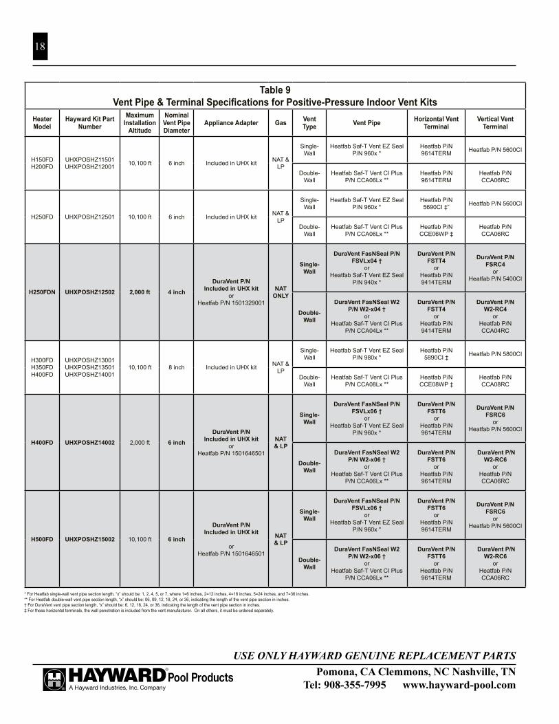
VENT SIzINGVent pipe diameter must match the vent pipe diameter on the heater (see Table 9). The vent pipe must be
single or double-wall stainless steel sealed vent as listed in Table 9. Double-wall vent must be used in non-conditioned spaces. The maximum total length of vent pipe, and number of 90-degree elbows cannot exceed the limits specified in Table 8.
The venting system must be installed in accordance with the vent manufacturer’s installation instructions and guidelines. The installer is urged to visit the vent system manufacturer’s website (see below) and review the installation information found there.
VENT TERMINATIONThe vent system must terminate with a vent terminal approved for this pool heater. Termination may be
either horizontal or vertical. See Table 9 for vent terminals which are approved.
OBTAINING VENT PIPE AND TERMINALSHayward offers a variety of double-wall vent components, including terminals, elbows, and straight
lengths, which will satisfy the needs of most applications. The available parts are listed in the service parts section in the back of this manual. Also, Hayward publishes an instruction sheet which can be used as a guide in specifying installations. It can be obtained on Hayward’s website at www.hayward-pool.com. If you need more specialized fittings, you may order them directly from the manufacturer, or one of their authorized deal-ers. To locate an authorized dealer for venting parts, contact the appropriate manufacturer at:
M&G DuraVent Inc. Selkirk Corporation6 Jupiter Ln. Heatfab DivisionColonie, Ny 12205 OR 130 Industrial Blvd(800) 835-4429 Turners Falls, MA 01376www.duravent.com (800) 772-0739
www.heatfab.com
Number of 90-degree Elbows
Maximum Vent Pipe Length
(horizontal & vertical)0 50 ft1 50 ft2 40 ft3 30 ft
Table 8Maximum Vent Pipe Length and Number of Elbows for
Positive-Pressure Vent Systems
Pomona, CA Clemmons, NC Nashville, TNTel: 908-355-7995 www.hayward-pool.com
USE ONLY HAYWARD GENUINE REPLACEMENT PARTS
18
Table 9Vent Pipe & Terminal Specifications for Positive-Pressure Indoor Vent Kits
Heater Model
Hayward Kit Part Number
Maximum Installation
Altitude
Nominal Vent Pipe Diameter
Appliance Adapter Gas Vent Type Vent Pipe Horizontal Vent
TerminalVertical Vent
Terminal
H150FDH200FD
UHXPOSHZ11501UHXPOSHZ12001 10,100 ft 6 inch Included in UHX kit NAT &
LP
Single-Wall
Heatfab Saf-T Vent EZ Seal P/N 960x *
Heatfab P/N 9614TERM Heatfab P/N 5600CI
Double-Wall
Heatfab Saf-T Vent CI Plus P/N CCA06Lx **
Heatfab P/N 9614TERM
Heatfab P/N CCA06RC
H250FD UHXPOSHZ12501 10,100 ft 6 inch Included in UHX kit NAT & LP
Single-Wall
Heatfab Saf-T Vent EZ Seal P/N 960x *
Heatfab P/N 5690CI ‡” Heatfab P/N 5600CI
Double-Wall
Heatfab Saf-T Vent CI Plus P/N CCA06Lx **
Heatfab P/N CCE06WP ‡
Heatfab P/N CCA06RC
H250FDN UHXPOSHz12502 2,000 ft 4 inch
DuraVent P/N Included in UHX kit
orHeatfab P/N 1501329001
NAT ONLy
Single-Wall
DuraVent FasNSeal P/N FSVLx04 †
orHeatfab Saf-T Vent EZ Seal
P/N 940x *
DuraVent P/N FSTT4
orHeatfab P/N 9414TERM
DuraVent P/N FSRC4
orHeatfab P/N 5400CI
Double-Wall
DuraVent FasNSeal W2 P/N W2-x04 †
orHeatfab Saf-T Vent CI Plus
P/N CCA04Lx **
DuraVent P/N FSTT4
orHeatfab P/N 9414TERM
DuraVent P/N W2-RC4
orHeatfab P/N CCA04RC
H300FDH350FDH400FD
UHXPOSHZ13001UHXPOSHZ13501UHXPOSHZ14001
10,100 ft 8 inch Included in UHX kit NAT & LP
Single-Wall
Heatfab Saf-T Vent EZ Seal P/N 980x *
Heatfab P/N 5890CI ‡ Heatfab P/N 5800CI
Double-Wall
Heatfab Saf-T Vent CI Plus P/N CCA08Lx **
Heatfab P/N CCE08WP ‡
Heatfab P/N CCA08RC
H400FD UHXPOSHz14002 2,000 ft 6 inch
DuraVent P/N Included in UHX kit
orHeatfab P/N 1501646501
NAT & LP
Single-Wall
DuraVent FasNSeal P/N FSVLx06 †
orHeatfab Saf-T Vent EZ Seal
P/N 960x *
DuraVent P/N FSTT6
orHeatfab P/N 9614TERM
DuraVent P/N FSRC6
orHeatfab P/N 5600CI
Double-Wall
DuraVent FasNSeal W2 P/N W2-x06 †
orHeatfab Saf-T Vent CI Plus
P/N CCA06Lx **
DuraVent P/N FSTT6
orHeatfab P/N 9614TERM
DuraVent P/N W2-RC6
orHeatfab P/N CCA06RC
H500FD UHXPOSHz15002 10,100 ft 6 inch
DuraVent P/N Included in UHX kit
orHeatfab P/N 1501646501
NAT & LP
Single-Wall
DuraVent FasNSeal P/N FSVLx06 †
orHeatfab Saf-T Vent EZ Seal
P/N 960x *
DuraVent P/N FSTT6
orHeatfab P/N 9614TERM
DuraVent P/N FSRC6
orHeatfab P/N 5600CI
Double-Wall
DuraVent FasNSeal W2 P/N W2-x06 †
orHeatfab Saf-T Vent CI Plus
P/N CCA06Lx **
DuraVent P/N FSTT6
orHeatfab P/N 9614TERM
DuraVent P/N W2-RC6
orHeatfab P/N CCA06RC
* For Heatfab single-wall vent pipe section length, “x” should be: 1, 2, 4, 5, or 7, where 1=6 inches, 2=12 inches, 4=18 inches, 5=24 inches, and 7=36 inches.** For Heatfab double-wall vent pipe section length, “x” should be: 06, 09, 12, 18, 24, or 36, indicating the length of the vent pipe section in inches.† For DuraVent vent pipe section length, “x” should be: 6, 12, 18, 24, or 36, indicating the length of the vent pipe section in inches.‡ For these horizontal terminals, the wall penetration is included from the vent manufacturer. On all others, it must be ordered separately.

Pomona, CA Clemmons, NC Nashville, TNTel: 908-355-7995 www.hayward-pool.com
USE ONLY HAYWARD GENUINE REPLACEMENT PARTS
19
REVERSIBLE WATER CONNECTIONS:This heater is designed so that it can be installed with the water connections located on either the right or
left side. Heaters are factory-shipped with right-side water connections. To move the connections to the left side follow the instructions below. A trained service technician should perform these steps before the heater is installed.
PROCEDURE:1. Before beginning, be aware that it is not necessary to re-
move the water header from the heat exchanger. When this procedure is complete, the water inlet will be located at the BACK of the heater. The water outlet will be lo-cated at the FRONT.
2. Remove screws and remove both of the upper plastic heater side panels (see Figure 7 and Figure 8). Note the wires that pass through a hole in the heater side panel go through a split-bushing, which will allow separation of the wires from the panel without disconnecting them.
3. Disconnect the 2 wires connecting the heater wire har-ness to the heat exchanger header. One is located on the water pressure switch and one is located on the tempera-ture limit switch, both on the top of the header. Pull these wires into the heater cabinet from the hole in the right-hand metal side panel in the heater, and re-route them out through the left-hand metal side panel in the heater.
4. Remove countersunk screws on the heater top and remove louvered exhaust panel on heater top (see Figure 88).
5. Remove the heater top flue cover by removing 3 screws on each side of the heater (see Figure 8).6. Remove screws and remove rain shield assembly (see Figure 8). Note that there are screws which hold the
rain shield assembly to the heat exchanger tube sheets, which also must be removed.7. Remove the front access panel (see Figure 8).8. Disconnect water temperature sensor plug from the ignition control board located inside the heater (see
Figure 8).9. Pull the water temperature sensor wires out of the heater cabinet through the hole in the right-hand metal
side panel.10. Lift and rotate the heat exchanger. Do not flip. Use care when setting the heat exchanger in place not to
damage the white sealing gaskets or combustion chamber.11. Route the water temperature sensor wires into the heater cabinet through the hole in the left-hand metal side
panel, and re-connect to the ignition control board.12. Re-connect the heater wire harness to the water pressure switch and temperature limit.13. Reverse the above steps to reassemble the heater.
Figure 14
Screw Locations
Figure 7: Screw locations on side of unit

Pomona, CA Clemmons, NC Nashville, TNTel: 908-355-7995 www.hayward-pool.com
USE ONLY HAYWARD GENUINE REPLACEMENT PARTS
20
1303264301 rev BPage 2 of 2
Front Access Panel
Ignition Control Circuit Board
Drain Plug or Valve
Temperature Limit Switches
Upper Plastic Heater Side Panel
Upper Plastic Heater Side Panel
Heat ExchangerAssembly
Pressure Switch Port
Rain Shield Assembly
Top Flue Cover
Louvered Exhaust Panel
Figure 2
Figure 8: Sub-Assemblies

Pomona, CA Clemmons, NC Nashville, TNTel: 908-355-7995 www.hayward-pool.com
USE ONLY HAYWARD GENUINE REPLACEMENT PARTS
21
GAS SUPPLy AND PIPING:To properly size the gas piping for the heater, refer to Tables 10, 11, 12, and 13, depending on natural
or propane gas, and single-stage or 2-stage regulation. Follow local gas codes for proper gas line material selection (copper, iron, plastic, etc.). It is VERy IMPORTANT when installing a propane heater on a 2-stage regulation system to follow the gas line sizing data in Table 13 without exception.
Distance from Gas Meter to Heater Gas
Valve Inlet
Model H150FDN H200FDN H250FDN H300FDN H350FDNbtu/hr input 150,000 200,000 250,000 300,000 350,000
Line MaterialI ron or Plastic PipeI ron or Plastic Pipe Iron or Plastic Pipe Iron or Plastic Pipe Iron or Plastic Pipe
0 to 50 ft 3/4" 1" 1" 1-1/4" 1-1/4" "50 to 100 ft 1" 1" 1-1/4" 1-1/4" 1-1/4" "
100 to 200 ft 1-1/4" 1-1/4" 1-1/4" 1-1/2" 1-1/2" "200 to 300 ft 1-1/4" 1-1/4" 1-1/2" 2" 2"
H400FDN400,000
Iron or Plastic Pipe
1-1/41-1/41-1/2
2"
Table 10Natural Gas Pipe Sizing, Low-Pressure, Single-Stage Regulation
Table 11Propane Gas Pipe Sizing, Low-Pressure, Single-Stage Regulation
Table 12Natural Gas Pipe Sizing, High-Pressure, 2-Stage Regulation
Based upon an inlet gas pressure of 0.5 psig or less at a pressure drop of 0.5 in-wc
Distance from Tank Regulator
Outlet to Heater Gas Valve Inlet
Model H150FDP H200FDP H250FDP H300FDP H350FDP H400FDPbtu/hr input 150,000 200,000 250,000 300,000 350,000 400,000
Line Material Iron Pipe Tubing Iron Pipe Tubing Iron Pipe Tubing Iron Pipe Tubing Iron Pipe Tubing Iron Pipe Tubing
0 to 50 ft 3/4" 7/8" 3/4" 7/8" 1" 1-1/8" 1" 1-1/8" 1" 1-1/8" 1" ---50 to 100 ft 3/4" 1-1/8" 1" 1-1/8" 1" 1-1/8" 1" --- 1-1/4" --- 1-1/4" ---100 to 200 ft 1" 1-1/8" 1" --- 1-1/4" --- 1-1/4" --- 1-1/4" --- 1-1/4" ---200 to 300 ft 1" --- 1-1/4" --- 1-1/4" --- 1-1/4" --- 1-1/4" --- 1-1/2" ---
Based upon an inlet gas pressure of 11 in-wc at a pressure drop of 0.5 inch w.c.
Distance from Outlet of 1st Stage Regulator to Inlet of 2nd Stage
Regulator
Model H150FDN H200FDN H250FDN H300FDN H350FDN H400FDNbtu/hr input 150,000 200,000 250,000 300,000 350,000 400,000
Line Material Iron or Plastic Pipe
Iron or Plastic Pipe
Iron or Plastic Pipe
Iron or Plastic Pipe
Iron or Plastic Pipe
Iron or Plastic Pipe
First Stage *0 to 50 ft 1/2" 1/2" 1/2" 1/2" 1/2" 1/2"
50 to 100 ft 1/2" 1/2" 1/2" 1/2" 3/4" 3/4"100 to 150 ft 1/2" 1/2" 1/2" 3/4" 3/4" 3/4"
Second Stage ** 0 to 10 ft 3/4" 3/4" 3/4" 3/4" 3/4" 3/4"
* Based upon an inlet gas pressure of 2 psig at a pressure drop of 1 psi** Based upon an inlet gas pressure of 10 in-wc at a pressure drop of 0.5 in-wc
H500FDN500,000
Iron or Plastic Pipe
2"2"
"1-1/2"1-1/4
H500FDN500,000
Iron Pipe Tubing
1"1-1/4"1-1/4"1-1/2"
---------
H500FDN500,000
Iron or Plastic Pipe1/2"3/4"3/4"
1"
---

Pomona, CA Clemmons, NC Nashville, TNTel: 908-355-7995 www.hayward-pool.com
USE ONLY HAYWARD GENUINE REPLACEMENT PARTS
22
Table 13Propane Gas Pipe Sizing, High-Pressure, 2-Stage Regulation
* Based upon an inlet gas pressure of 10 psig at a pressure drop of 1 psi** Based upon an inlet gas pressure of 11 in-wc at a pressure drop of 0.5 in-wc
Distance from
Tank Regulator
Outlet to
Heater Gas
Valve Inlet
Model H150FDP H200FDP H250FDP H300FDP H350FDP H400FDPbtu/hr input 150,000 200,000 250,000 300,000 350,000 400,000
Line Material
Iron Pipe Tubing Iron
Pipe Tubing Iron Pipe Tubing
Iron Pipe
TubingIron Pipe
TubingIron Pipe
Tubing
First Stage *0 to 50 ft 1/2" 1/2" 1/2" 1/2" 1/2" 1/2" 1/2" 1/2" 1/2" 1/2" 1/2" 1/2"
50 to 100 ft 1/2" 1/2" 1/2" 1/2" 1/2" 1/2" 1/2" 1/2" 1/2" 5/8" 1/2" 5/8"100 to 150 ft 1/2" 1/2" 1/2" 1/2" 1/2" 1/2" 1/2" 5/8" 1/2" 5/8" 1/2" 5/8"
Second
Stage ** 0 to 10 ft 1/2" 5/8" 1/2" 5/8" 1/2" 3/4" 3/4" 3/4" 3/4" 7/8" 3/4" 7/8"
H500FDP500,000
Iron Pipe
Tubing
1/2" 1/2"1/2" 5/8"1/2" 5/8"
3/4" 1"

Pomona, CA Clemmons, NC Nashville, TNTel: 908-355-7995 www.hayward-pool.com
USE ONLY HAYWARD GENUINE REPLACEMENT PARTS
23
GAS SUPPLy INSTALLATION:The heater is shipped from the factory with the gas connection
located on the left-hand side of the heater cabinet. Insert the pipe to the gas valve through the grommet in the cabinet side (see Figure 10.) A union should be installed outside the heater cabinet for easy removal of the gas manifold assembly during service.
A CSA certified main gas shutoff valve must be installed outside the cabinet and within 6 feet of the heater. This valve must have an I.D. large enough to supply the proper amount of gas volume to the heater. See Figure 9.
ATTENTION: Apply joint compound (pipe dope) sparingly and only to the male threads of pipe joints. Do not apply joint compound to the first two threads. Use joint compounds resistant to the action of liquefied petroleum gas. Do not overtighten the gas inlet pipe or damage may result.
ATTENTION : Do not use flexible appliance connectors on any gas connections unless the con-nector is CSA approved for outdoor installation, is marked with BTUH capacity (which must be equal to or greater than the heater rated input) and the type of gas (natural or LP).
Reduction of gas supply pipe or tubing to the inlet of the heater gas valve must be made at the valve only and must match the valve inlet size (3/4” or 1” NPT).
If more than one appliance is installed on the gas line, consult the local gas company for the proper gas line size.
Questions on the installation of the proper gas line size can be directed to Hayward Technical Service.
NATURAL GAS:The gas meter must have the capacity to supply enough gas to the pool heater and any other gas appli-
ances if they are on the same pipeline (Example: 225 meter = 225,000 BTUH). If doubt exists as to the meter size, consult the local gas utility for assistance. Natural gas must be “pipeline quality” supplied from a natural gas utility company. Hayward will not be responsible for heaters that soot up due to improper meter and gas line sizing resulting in improper gas volume, or heaters that are damaged in any way if connected to a natural gas well.
PROPANE GAS:All propane gas tanks must be located outdoors and away from pool/spa structure and in accordance with
the standard for storage and handling of propane gas, ANSI/NFPA 58 (latest edition) and applicable local codes. If the propane gas tank is installed underground, the discharge of the regulator vent must be above the highest probable water level.
Propane tanks must have sufficient capacity to provide adequate vaporization for the full capacity of the equipment at the lowest expected temperatures. Consult a propane company expert for correct sizing.
Gas Inlet
Supply voltage inlet
Low voltage inlet
Bonding lug
Figure 10: Junction Box Cover
Figure 9: Gas Piping

Pomona, CA Clemmons, NC Nashville, TNTel: 908-355-7995 www.hayward-pool.com
USE ONLY HAYWARD GENUINE REPLACEMENT PARTS
24
ATTENTION: Whenever a high-pressure double regulation system is utilized for propane gas, consult a propane expert for accurate pipe and pressure sizing. Make sure that 1st and 2nd stage regulators are large enough to handle the BTUH input listed for the heater(s) being used. Hayward will not be responsible for heaters that soot up due to improper gas line or propane tank siz-ing resulting in improper gas volume.
WATER PIPING:The heater is designed for use with pool and spa/hot tub water only, as furnished by municipal water dis-
tribution systems. The warranty does not cover heater use with mineral water, seawater (PPM>5000), or other non-potable waters.
Do not install any restriction in the water pipe between the heater outlet and the pool/spa with the exception of:
1. three-way switching valve2. in-line chlorinator3. chlorinator check valve
WARNING: EXPLOSION HAZARD Blockage of water flow from heater return to pool may result in fire or explosion causing property damage, personal injury, or loss of life.
The heater is equipped with CPVC flanged pipe nip-ples to accommodate water piping to and from the pool or spa. These pipe nipples will accept piping by solvent welding (PVC glue). The fittings will accept either a 2” pipe, or a 2 1/2” pipe fitting, and seal to the heater header with rubber gaskets. On plastic headers, the fittings are secured in place with plastic union nuts, and on bronze headers (ASME models), the fittings are secured in place with bolts. Assemble these parts to the heater prior to plumbing. Tighten union nuts (or bolts) securely before gluing fittings to the ends of the pipe nipples. See Figure 11.
The CPVC flanged pipe nipples must be installed on the heater inlet and outlet without modification. Pipe, fittings, valves, and any other element of the filter system may be made of plastic materials, if acceptable to the authority having jurisdiction.
Heat sinks, heat tapes, firemen switches, and check valves are not required on the heater. However, if there is any chance of “back-siphoning” of hot water when the pump stops running, it is suggested that a check valve be used on the heater inlet pipe.
The built-in bypass inside the header will maintain proper flow through the heat exchanger if the flow rate is within the range for the heater. See Table 14. The minimum flow rate is to be calculated or measured with the in-floor cleaning system in use, if the pool is so equipped, as well as any other jets or other demands on the water flow.
Gaskets Fittings BoltsHeaterHeader
Bronze Header (ASME)
Plastic Header
Gaskets Fittings Union NutsHeaterHeader
Figure 11: Pipe nipples

Pomona, CA Clemmons, NC Nashville, TNTel: 908-355-7995 www.hayward-pool.com
USE ONLY HAYWARD GENUINE REPLACEMENT PARTS
25
If the normal pump and filter system flow rate exceeds 125 gpm then a manual bypass valve must be installed as shown in Figure 12. Damage caused by flow rates outside this range will void the manufacturer’s warranty.
The installation is as follows:1. Install a flow meter on the outlet line of the heater.2. Adjust the manual bypass valve until the flow
rate is within the flow rate range specified for the heater.
3. Once the valve is set, note the position and remove the valve handle to prevent further adjustment.
ATTENTION: Improperly adjusted manual bypass valves will result in damage to the heater if the flow rates are not maintained as specified in Table 14 under all operating conditions. The heat exchang-er will fail and this damage will not be covered under the Hayward warranty.
Table 14: Allowable Water Flow Rate Range
Model Minimum Flow Rate (GPM)
Maximum Flow Rate (GPM)
H150FD H200FD 20 125
H250FD H300FD 25 125
H350FD H400FD 30 125
H500FD 40 125
Figure 12: Manual Bypass valve

Pomona, CA Clemmons, NC Nashville, TNTel: 908-355-7995 www.hayward-pool.com
USE ONLY HAYWARD GENUINE REPLACEMENT PARTS
26
INSTALLATION ABOVE POOL/SPA SURFACE:If the heater is installed less than three (3) feet above the sur-
face of the pool/spa water, install eyeball fittings or directional flow fittings on the end of the return water line to the pool/spa to create adequate back pressure at the heater to operate the pressure safety switch when the filter pump is running.
If the heater is installed more than three (3) feet above the surface of the pool/spa water, install a loop as shown in Figure 15 to prevent drainage of water in the heater during a filter change.
For installation below the pool/spa surface, refer to Section III.
Figure 13: Typical plumbing to pool Figure 14: Multiple heater system
Figure 16: Automatic chlorinator
Figure 15: Heater installationabove pool/spa
AUTOMATIC CHLORINATORS AND CHEMICAL FEEDERS:
If used, a chlorinator must be installed downstream from the heater in the pool return line and at a lower elevation than the heater as shown in Figure 16. Install a separate positive seal corrosion resistant check valve between the heater outlet and the chlorinator to prevent highly concentrated sanitizer from back siphoning into the heater. Back siphoning usually occurs when the pump is shut off and a pressure differential is created.
Figure 13 illustrates a typical pool piping diagram and layout for the pool equipment.Figure 14 illustrates a multiple heater installation for very large pools with and without a manual
bypass valve.
Pomona, CA Clemmons, NC Nashville, TNTel: 908-355-7995 www.hayward-pool.com
USE ONLY HAYWARD GENUINE REPLACEMENT PARTS
27
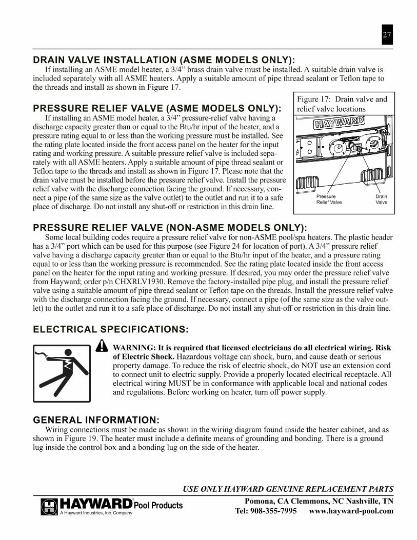
DRAIN VALVE INSTALLATION (ASME MODELS ONLy):If installing an ASME model heater, a 3/4” brass drain valve must be installed. A suitable drain valve is
included separately with all ASME heaters. Apply a suitable amount of pipe thread sealant or Teflon tape to the threads and install as shown in Figure 17.
PRESSURE RELIEF VALVE (ASME MODELS ONLy):If installing an ASME model heater, a 3/4” pressure-relief valve having a
discharge capacity greater than or equal to the Btu/hr input of the heater, and a pressure rating equal to or less than the working pressure must be installed. See the rating plate located inside the front access panel on the heater for the input rating and working pressure. A suitable pressure relief valve is included sepa-rately with all ASME heaters. Apply a suitable amount of pipe thread sealant or Teflon tape to the threads and install as shown in Figure 17. Please note that the drain valve must be installed before the pressure relief valve. Install the pressure relief valve with the discharge connection facing the ground. If necessary, con-nect a pipe (of the same size as the valve outlet) to the outlet and run it to a safe place of discharge. Do not install any shut-off or restriction in this drain line.
PRESSURE RELIEF VALVE (NON-ASME MODELS ONLy):Some local building codes require a pressure relief valve for non-ASME pool/spa heaters. The plastic header
has a 3/4” port which can be used for this purpose (see Figure 24 for location of port). A 3/4” pressure relief valve having a discharge capacity greater than or equal to the Btu/hr input of the heater, and a pressure rating equal to or less than the working pressure is recommended. See the rating plate located inside the front access panel on the heater for the input rating and working pressure. If desired, you may order the pressure relief valve from Hayward; order p/n CHXRLV1930. Remove the factory-installed pipe plug, and install the pressure relief valve using a suitable amount of pipe thread sealant or Teflon tape on the threads. Install the pressure relief valve with the discharge connection facing the ground. If necessary, connect a pipe (of the same size as the valve out-let) to the outlet and run it to a safe place of discharge. Do not install any shut-off or restriction in this drain line.
ELECTRICAL SPECIFICATIONS:
WARNING: It is required that licensed electricians do all electrical wiring. Risk of Electric Shock. Hazardous voltage can shock, burn, and cause death or serious property damage. To reduce the risk of electric shock, do NOT use an extension cord to connect unit to electric supply. Provide a properly located electrical receptacle. All electrical wiring MUST be in conformance with applicable local and national codes and regulations. Before working on heater, turn off power supply.
GENERAL INFORMATION:Wiring connections must be made as shown in the wiring diagram found inside the heater cabinet, and as
shown in Figure 19. The heater must include a definite means of grounding and bonding. There is a ground lug inside the control box and a bonding lug on the side of the heater.
PressureRelief Valve
DrainValve
Figure 34
Figure 17: Drain valve and relief valve locations

Pomona, CA Clemmons, NC Nashville, TNTel: 908-355-7995 www.hayward-pool.com
USE ONLY HAYWARD GENUINE REPLACEMENT PARTS
28
MAIN POWER:WARNING - Power connections supplied to the heater must be in accordance with National Electric Code (NEC) and local electric codes. The NEC contains no standards requiring Ground-Fault Interrup-tion protection (via GFI Circuit Breaker or otherwise) of “Fixed” or “Stationary” equipment, under article 680: Swimming Pools, Fountains, & Similar Installations.
BONDING:CAUTION - This heater must be connected to a bonding grid with a solid copper conductor wire gauge 8 AWG or larger. All Hayward heaters are designed for copper conductors only. The National Electrical Code (NEC), and most other codes require that all metallic components of a pool structure, including reinforcing steel, metal fittings and above ground equipment, be bonded together with a solid copper conductor wire gauge 8 AWG or larger. The heater, along with pumps and other pool equipment must be connected to this bonding grid. A bonding lug is provided on the side of the heater to ensure that this requirement is met.
ELECTRICAL CONNECTIONS:The heater is equipped with a hot surface ignition control system that automatically lights the burners. An
external power supply is required to power the control system. The electrical specifications for this heater are 120/240VAC, 60Hz, 1-phase, 5.5A maximum current. It is recommended that circuit protection for the heater circuit be rated at 15 Amperes.
The heater is shipped from the factory wired for use with 240VAC, 60 Hz field power supply. To convert the heater to 120VAC, 60 Hz operation remove the 240VAC voltage selector jumper from the ignition control board and replace it with the 120VAC jumper. These jumpers are tie-wrapped together and are located on the fuse board. See Figure 21 for location of the fuse board. All wiring connections to the heater must be made in accordance with the latest edition of the National Electrical Code ANSI/NFPA 70, unless local code require-ments specify otherwise. In Canada, follow CSA C22.1 Canadian Electrical Code, Part 1. The heater must be electrically grounded and bonded in accordance with local codes or, in the absence of local codes, with National Electrical Code, ANSI/NFPA 70. The heater may be installed with the electrical service and remote control entering the heater cabinet on either the left or right sides of the heater. The heater is equipped with (4) openings for electrical entry. Any unused openings must be plugged (these are supplied). Field power wiring connections are to be made to the terminal block located in the upper compartment inside the junction box (see Figure 18). The heater has 2 junction boxes (one on each side of the heater). Only one junction box should be used for field power wiring.

29
Pomona, CA Clemmons, NC Nashville, TNTel: 908-351-5400 www.haywardpool.com
USE ONLY HAYWARD GENUINE REPLACEMENT PARTS
2-WIRE REMOTE CONTROL CONNECTION:To configure the heater for 2- wire remote thermostat control, use the “MODE” key on the heater keypad
to put the control into “STANDBy” mode. Then press and hold both the “( - )” and “MODE” keys for 3 sec-onds until the display shows the code “bo”.
On the remote control wiring terminal block (Figure 18), connect the appropriate wires from the remote control to the terminals adjacent to the ORANGE wire (“POOL”) and WHITE wire (“24V”).
To operate the heater by remote thermostat, the heater’s control must be in either “POOL” or “SPA” mode. The display will show “bo”. The “POOL” or “SPA” LED will be illuminated. The remote thermostat will operate the heater. The heater’s thermostat will function to limit the water temperature to a maximum of 104°F.
3-WIRE REMOTE CONTROL CONNECTION:On the remote control wiring terminal block (Figure 18), connect the appropriate wires from the remote
control to the terminals adjacent to the ORANGE wire (“POOL”), WHITE wire (“24V”), and RED wire (“SPA”). To operate the heater with a remote 3-wire switch, the heater’s control must be in “STANDBy” mode. The “STANDBy” LED will be illuminated. When the remote switch is set to “Pool/Low” the “POOL” LED will be illuminated and the water temperature will be displayed. When the remote switch is set to “Spa/High” the “SPA” LED will be illuminated and the water temperature will be displayed. The heater will use its internal thermostat to regulate the water temperature to the set point of the mode selected.
L (120V)or
L1 (240V)
N (120V)or
L2 (240V) Ground
Field PowerWiring TerminalBlock
RemoteConnectionTerminal Block
Spa (RED) Common(WHITE)
Pool(ORANGE)
Figure 18: Junction Box connectionsREMOTE CONTROL CONNECTION:
The heater is equipped for con-nection to an external 2-wire remote thermostat or a 3-wire remote switch. A 2-wire thermostat has its own tempera-ture sensor for regulating water tempera-ture. A 3- wire remote switch allows the “POOL” or “SPA” models to be re-motely selected. Connect remote wiring to the terminal block located in the lower compartment inside the junction box (see Figure 18). The heater has 2 junction boxes (one on each side of the heater). Only one junction box should be used for remote wiring. Do not remove the wires connected to the remote connection ter-minal block. Remote wiring must be run in a separate conduit. Use 22 AWG wire for runs less than 30 feet. Use 20 AWG wire for runs over 30 feet. The maximum allowable run is 200 feet.

Pomona, CA Clemmons, NC Nashville, TNTel: 908-355-7995 www.hayward-pool.com
USE ONLY HAYWARD GENUINE REPLACEMENT PARTS
30
1303103801 rev L
Wiring C
onnection Diagram
/ Schéma de C
onnexion de Câblage
Forced Draft G
as Heaters / C
haudière Gas à Air pulsé
Flue Gas Tem
peratureLim
it Switch
Com
mutateur lim
iteur detem
pérature des gaz decom
bustion
Figure 19: Wiring connection diagram.

31
Figure 20: Lighting & Oper-ating Instructions label

Pomona, CA Clemmons, NC Nashville, TNTel: 908-355-7995 www.hayward-pool.com
USE ONLY HAYWARD GENUINE REPLACEMENT PARTS
32
(H150FD and H200FD models)
(H250FD, H300FD, H350FD, and H400FD models)
BlowerVacuumSwitch
Fuse Board
Gas Valve
Sight Glass
IgniterAccess Panel
Gas Manifold Flame Sensor
Air Box
Blower
Ignition ControlBoard
Transformer
Keypad
Flame Sensor
Air Box
Blower
Ignition ControlBoard
Transformer
Keypad
Blower VacuumSwitch Fuse Board
Gas Valve
Sight Glass
IgniterAccess Panel
Gas Manifold
(H500FD models)
Gas Manifold
IgniterAccess Panel Flame Sensor
Sight Glass
Air Box
Blower
Fuse Board
Ignition ControlBoard
Keypad
Gas Valve
Blower VacuumSwitch
Transformer
Vent PressureSwitch
Vent PressureSwitch
Vent PressureSwitch
Figure 21: Location of Components
GENERAL: Some of the following procedures will require the heater to be operating. Full lighting and shutdown instruc-
tions are included on the lighting and operating label affixed to the inside of the front access panel. The heater automatically lights in response to a call for heat, and automatically shuts down when that call for heat is satisfied.
Water must be flowing through the heater during operation. Check that the pump is operating and the system is filled with water and purged of all air prior to starting the heater.
SECTION III. INSTALLER CHECK-OUT AND START-UP

Pomona, CA Clemmons, NC Nashville, TNTel: 908-355-7995 www.hayward-pool.com
USE ONLY HAYWARD GENUINE REPLACEMENT PARTS
33
GAS LINE TESTING:The appliance and its gas connection must be leak tested before placing the appliance in operation. The
heater and its individual shutoff valve must be disconnected from the gas supply during any pressure testing of that system at test pressure in excess of ½ psig (3.45 kPa). The heater must be isolated from the gas sup-ply piping system by closing its individual manual shutoff valve during any pressure testing of the gas supply piping system at test pressure equal to or less than ½ psig (3.45 kPa).
Gas supply line must be capped when not connected. After pressure testing, reconnect the gas piping to the gas valve. Turn gas supply “ON” and test all pipe and tubing joints for leaks. Use a soap and water solution.
WARNING: EXPLOSIVE HAZARD. The use of an open flame to check for gas leaks could cause an explosion resulting in severe injury and/ or death. Shut off gas and fix even the smallest leak right away. Be sure to leak test the heater gas manifold fittings using the above procedure once the heater is in operation.
GAS PRESSURE TESTING:The following gas pressure requirements are important to the proper operation of the burners in gas heat-
ers. Improper gas pressure or gas volume will create the following conditions:1. Flame burns totally yellow.2. Flame lifts off burner.3. Heat exchanger soots up. The gas pressure regulator on all heaters is preset at the factory,
but the setting should be verified by the installer to ensure proper operation.
If gas pressure is inadequate, check for undersize piping between the gas meter and the heater or for a low-capacity gas meter.
GAS PRESSURE TEST PROCEDURE:Refer to Figure 22 for the location components used in this procedure on the specific model of UHS
heater being serviced.
INCREASE PRESSURE
DECREASE PRESSURE
For all valves, adjust regulator pressureby removing the screw cap and turningthe adjustment screw as shown below.
ON/OFFknob
Inletpressuretap plug
Manifoldpressuretap plug Electrical
terminals
Regulatoradjustmerntscrew underthis screwcap
Valve for H150FD, H200FD, H250FD, H300FD, H350FD, and H400FD models
ON/OFFknob
Inletpressuretap plug
Electricalterminals
Regulatoradjustmerntscrew underthis screwcap
Valve for H500FDN modelManifold pressure to be taken at the pressure tap located onthe gas manifold just after the gas valve for H500FDN units.
ON/OFFswitch
Inletpressuretap plug
Manifoldpressuretap plug
Electricalterminals
Regulatoradjustmerntscrew underthis screwcap
Valve for H500FDP model
Figure 22: Gas Valves

Pomona, CA Clemmons, NC Nashville, TNTel: 908-355-7995 www.hayward-pool.com
USE ONLY HAYWARD GENUINE REPLACEMENT PARTS
34
1. Obtain the necessary equipment:a. Manometer to read pressure in inches of water columnb. 1/8” pipe nipple (1/8” thread x 1” long)c. 3/16” hex wrenchd. Flat screwdriver
2. Remove the 1/8” plug from the gas valve.3. Install the 1/8” pipe nipple into the gas valve.4. Attach the manometer to the pipe nipple.5. Turn on the water system and start the heater following the lighting & operating instructions on the
label affixed inside the front access panel. If there is more than one pool/spa heater connected to the gas supply line, turn each of those appliances “ON” while testing the heater.
6. Take a pressure reading with the heater running, the value should agree with those in Table 15. If the pressure is within the range of 1.8” - 2.0” w.c. (natural) or 6.8” - 7.0” w.c. (propane), then no further adjustment is needed.
7. If the gas pressure does not meet the above requirements the regulator must be adjusted.
8. Gas pressure regulator adjustment procedure:a. Remove the screw cap over the regulator
adjustment screw (see Figure 22).b. Turn the regulator adjustment screw
clockwise to increase pressure and coun-terclockwise to decrease pressure.
c. Replace the screw cap over the regulator adjustment screw.
WARNING EXPLOSION HAZARD: Do not remove the 1/8” pipe nipple with the valve in the “ON” position. The valve must be in the “OFF” position when the nipple is removed. Removal of the nipple with the gas valve “on” could cause an explosion resulting in severe injury and/or death.
9. Remove the 1/8” pipe nipple and replace the 1/8” pipe plug. If proper pressure cannot be achieved by adjusting the gas valve regulator, the installer must contact the gas supplier and request that the inlet pressure to the heater be set to within the gas pressure range shown in Table 15.
WARNING EXPLOSION HAZARD: Gas pressures in excess of those listed in Table 15 could cause a gas leak or diaphragm rupture. Gas leakage could cause an explosion resulting in severe injury or death.
Table 15: Correct gas pressuresPressure, in. w.c. FDN FDPFuel Natural PropaneManifold 1.8” - 2.0” w.c. 6.8” - 7.0” w.c.Inlet, minimum 4.5” w.c. 10.0” w.c.Inlet, maximum 10.5” w.c. 13.0” w.c.

Pomona, CA Clemmons, NC Nashville, TNTel: 908-355-7995 www.hayward-pool.com
USE ONLY HAYWARD GENUINE REPLACEMENT PARTS
35
WATER PRESSURE SWITCH TEST / ADJUSTMENT PROCEDURE:The pressure switch is preset at the factory for most typical, deck level installations. When the heater is located
above or below the level of the pool or spa, the pressure switch may require adjustment to compensate for the change in static head pressure. The following procedure is recommended when the switch needs adjustment and/or is replaced:
For Installations with Heater Above Water Level:1. Be sure the filter is clean before making the adjustment.2. Turn “ON” the filter pump and ensure all air is out of the water lines, and ensure water flow rate is at
least the rated minimum (see Table 14).3. Turn “ON” the heater and adjust the thermostat to create a call for heat.4. If the heater does not light, adjust the pressure switch by turning the adjustment knob on the pressure
switch counter-clockwise, until the heater lights. Turning the adjustment knob counterclockwise decreases the pressure needed to close the switch.
5. Check the function of the pressure switch by turning the filter pump on and off several times. The pool heater should turn off immediately when the pump is turned off. Never allow the heater to operate with less than the minimum rated water flow rate.
For Installations with Heater Below Water Level:1. Be sure the filter is clean before making the adjustment.2. Turn “ON” the filter pump and ensure all air is out of the water lines, and ensure water flow rate is at
least the rated minimum (see Table 14).3. Turn “ON” the heater and adjust the thermostat to create a call for heat.4. Turn the adjustment knob on the pressure switch clockwise, until the heater turns off, then turn the knob
¼ turn counter-clockwise, so that the heater turns back on. Turning the adjustment knob clockwise increases the pressure needed to close the switch.
5. Check the function of the pressure switch by turning the filter pump on and off several times. The pool heater should turn off immediately when the pump is turned off. Never allow the heater to operate with less than the minimum rated water flow rate.
TWO-SPEED PUMP:In a few cases the pressure from a two-speed pump is below the 1- pound minimum required to operate the wa-
ter pressure switch on the heater. This is apparent when the pressure switch cannot be further adjusted. In these cases the pump must be run at high speed to operate the heater. If the pump and piping arrangement are such that the re-quired 1-pound minimum pressure cannot be obtained, do not attempt to operate the heater. Correct the installation.
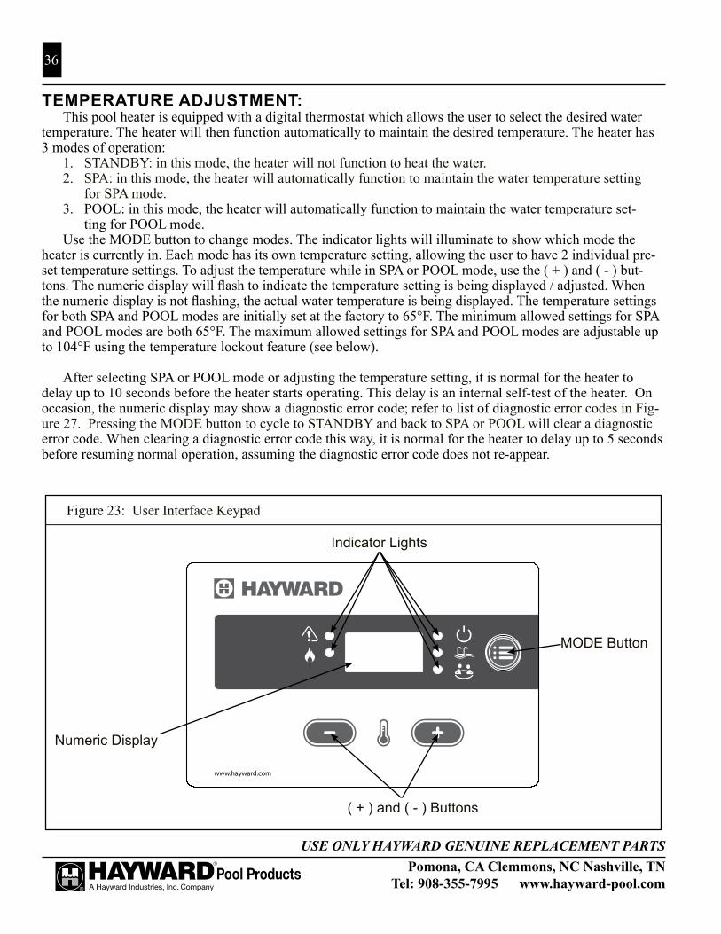
Pomona, CA Clemmons, NC Nashville, TNTel: 908-355-7995 www.hayward-pool.com
USE ONLY HAYWARD GENUINE REPLACEMENT PARTS
36
Figure 23: User Interface Keypad
TEMPERATURE ADJUSTMENT:This pool heater is equipped with a digital thermostat which allows the user to select the desired water
temperature. The heater will then function automatically to maintain the desired temperature. The heater has 3 modes of operation:
1. STANDBY: in this mode, the heater will not function to heat the water.2. SPA: in this mode, the heater will automatically function to maintain the water temperature setting
for SPA mode.3. POOL: in this mode, the heater will automatically function to maintain the water temperature set-
ting for POOL mode.Use the MODE button to change modes. The indicator lights will illuminate to show which mode the
heater is currently in. Each mode has its own temperature setting, allowing the user to have 2 individual pre-set temperature settings. To adjust the temperature while in SPA or POOL mode, use the ( + ) and ( - ) but-tons. The numeric display will flash to indicate the temperature setting is being displayed / adjusted. When the numeric display is not flashing, the actual water temperature is being displayed. The temperature settings for both SPA and POOL modes are initially set at the factory to 65°F. The minimum allowed settings for SPA and POOL modes are both 65°F. The maximum allowed settings for SPA and POOL modes are adjustable up to 104°F using the temperature lockout feature (see below).
After selecting SPA or POOL mode or adjusting the temperature setting, it is normal for the heater to delay up to 10 seconds before the heater starts operating. This delay is an internal self-test of the heater. On occasion, the numeric display may show a diagnostic error code; refer to list of diagnostic error codes in Fig-ure 27. Pressing the MODE button to cycle to STANDBY and back to SPA or POOL will clear a diagnostic error code. When clearing a diagnostic error code this way, it is normal for the heater to delay up to 5 seconds before resuming normal operation, assuming the diagnostic error code does not re-appear.
www.hayward.com
MODE Button
( + ) and ( - ) Buttons
Numeric Display
Indicator Lights

Pomona, CA Clemmons, NC Nashville, TNTel: 908-355-7995 www.hayward-pool.com
USE ONLY HAYWARD GENUINE REPLACEMENT PARTS
37
TEMPERATURE LOCK-OUT:The digital thermostat in this pool heater allows the user to lock the maximum temperature setting allowed.
This feature is useful for preventing unauthorized users from manually adjusting the temperature settings higher than desired. On a new heater, the maximum allowed temperature lock settings are initially set at the factory to 90°F for POOL mode, and 104°F for SPA mode. To adjust these settings, use the following procedure:
1. Use the MODE button to put the heater in STANDBY mode.2. Press and hold both the ( + ) and ( - ) buttons at the same time.3. After 3 seconds, the thermostat enters maximum temperature lock adjustment mode.4. The SPA indicator light illuminates and the numeric display shows the current SPA mode maximum
temperature lock setting. Both the SPA indicator light and the numeric display flashes rapidly when in adjustment mode.
5. Use the ( + ) and ( - ) buttons to set the desired maximum temperature lock setting. When finished, press the MODE button.
6. The POOL indicator light illuminates and the numeric display shows the current POOL mode maximum temperature lock setting. Both the POOL indicator light and the numeric display flashes rapidly when in adjustment mode.
7. Use the ( + ) and ( - ) buttons to set the desired maximum temperature lock. When finished, press the MODE button.
8. The heater will return to STANDBY mode
FAHRENHEIT VERSUS CELSIUS:The temperature can be displayed in Fahrenheit or Celsius. TO change the display, use the “MODE” but-
ton to place the heater in “STANDBy”. Then press and hold the “( + )” and “MODE” buttons until the display shows the °F/°C selection. Press the “( - )” button to toggle between selections. To accept the selection, press the “MODE” button. If the user does not act, the selection will be automatically accepted after 60 seconds.
HEATING MODE:The control continually compares the water temperature with the set point and the high limit temperature. When the water temperature is more than 1° below the set point a call for heat is generated and a heating cycle is initiated.
1. The control checks for open contacts at the blower vacuum switch.2. The control energizes the blower and the igniter. The igniter heat-up time is approximately 20 seconds.
The blower is running a pre-purge cycle during this time.3. The control checks for closed contacts at the blower vacuum switch.4. When the igniter reaches the proper temperature a 4-second trial for ignition begins. The control opens
the gas valve and monitors flame current. The igniter is turned off when flame is sensed or after 4 sec-onds.
5. The blower vacuum switch, the temperature limit switches, the vent pressure switch, the water pressure switch, the water temperature sensors, and the flame sensor are constantly monitored during a call for heat to assure the heater is operating properly.
6. When the thermostat is satisfied and the call for heat ends the control immediately de-energizes the gas valve. Flame is extinguished.
7. The control operates the blower during a 30-second post-purge period.

Pomona, CA Clemmons, NC Nashville, TNTel: 908-355-7995 www.hayward-pool.com
USE ONLY HAYWARD GENUINE REPLACEMENT PARTS
38
FAILURE TO LIGHT – RETRy:If the first ignition attempt fails during a normal heating cycle the control will make two (2) additional
ignition attempts:1. The control de-energizes the gas valve after the 4-second ignition trial ends.2. The control operates the blower during a 30-second post-purge period.3. The control monitors for open contacts at the blower vacuum switch.4. The control performs a gas valve relay check.5. A normal ignition sequence resumes with Item #2 in “Heating Mode” (above). If the third ignition
trial fails the control enters a safety lockout (or “hard” lockout) after the post purge period of the third failed trial.
6. The error code “IF” is displayed and the “SERVICE” indicator is illuminated.a. The control automatically resets and clears the “IF” error code without any user intervention after
60 minutes. If there is a call for heat after reset the control will make three (3) trials for ignition. If ignition is not established the control will again enter safety lockout for 60 minutes. This cycle will continue until ignition is established or the call for heat is removed.
b. The user can reset the control and clear the “IF” error code by pressing the “MODE” button to move through “STANDBy” and return to the previous mode (“SPA” or “POOL”).
LOSS OF FLAME – RECyCLE:If flame is established and then lost, the control will make ten (10) attempts at ignition. If flame is lost
within ten (10) seconds of ignition the control will respond within 2 seconds. If flame is lost more than ten (10) seconds after ignition the control will respond within 0.8 seconds.
1. The control de-energizes the gas valve and the blower.2. The control monitors for open contacts at the blower vacuum switch.3. The control performs a gas valve relay check.4. A normal ignition sequence resumes with Item #2 in “Heating Mode” (above).5. If the tenth ignition trial fails the control enters a safety lockout (or “hard” lockout) after the post-
purge period of the tenth failed trial.6. The error code “IF” is displayed and the “SERVICE” indicator is illuminated.
a. The control automatically resets after 60 minutes. If there is a call for heat after reset the control will make three (3) trials for ignition. If ignition is not established the control will again enter safety lockout for 60 minutes. If flame is established but is lost the control will make ten (10) attempts at ignition. This cycle will continue until ignition is established or the call for heat is removed.
b. The user can reset the control and clear the “IF” error code by pressing the “MODE” button to move through “STANDBy” and return to the previous mode (“SPA” or “POOL”).
KEyPAD INPUTS:The control accepts user inputs via the keypad on the front panel.
1. When changing the mode from “STANDBy” to either “SPA” or “POOL” there may be up to a 10- second delay for the blower fan to begin running. The control performs an internal self-test and then verifies that the blower vacuum switch contacts are open before energizing the blower.
2. It is normal for the heater to display a 1- to 2-second delay in responding to any keypad input.3. It is normal for the heater to display up to a 5-second delay when the keypad is used to reset the control
to clear an error code.4. The control will accept a mode change during lockout after 5 seconds. The control will continue to
display the error code and remain in lockout until it is reset. At reset the control will go to the last saved mode.

Pomona, CA Clemmons, NC Nashville, TNTel: 908-355-7995 www.hayward-pool.com
USE ONLY HAYWARD GENUINE REPLACEMENT PARTS
39
AUTOMATIC RESET TIME:The heater will automatically reset when an error condition is corrected and resume operation as detailed
in the table below. The heater can be manually reset using the keypad by cycling the mode button through “STANDBy” and back to the original operating mode (“SPA” or “POOL”).
PERIODIC INSPECTION:The heater is designed and built for long performance life when installed and operated according to the
manufacturer’s directions. Regular inspection by qualified service personnel is recommended to keep the heater working properly. The following inspection points are suggested to help maximize heater life.
1. Periodically check the venting on outdoor heaters. The heater’s venting areas (the louvered top panel) must never be obstructed in any way and minimum clearances must be observed to prevent restriction of combustion and ventilation air. Remember that shrubs grow and in time may obstruct a heater’s venting areas.
2. Check the venting of indoor heaters for looseness and possible leaks. Keep all openings for com-bustion and ventilation air clear and unobstructed.
3. Keep the entire pool heater area clean and free of all debris, combustible materials, gasoline, and other flammable vapors and liquids. Remove any leaves or paper from around the heater.
4. Do not store chlorine, other pool chemicals, or other corrosives in the vicinity of the heater.5. If the heater is operating on propane gas, the tank must not fall below 30% full or damage to the
heater may occur. Hayward will not be responsible for heaters that soot up due to improper gas level in the tank resulting in inadequate gas volume.
6. If another appliance is added to the gas line at a later date, consult the local gas company to be sure the gas line will have the capacity to supply both units at full input rating at the same time.
7. Do not use the heater if any part has been under water. Contact a qualified service technician to inspect the entire heater and replace any part of the control system or gas valve that was under water. If heater has been totally submerged in water it must be removed and the entire heater must be replaced.
8. An inspection program is a good preventative maintenance measure. Keep this manual in a safe place for future reference for yourself as well as for a service technician to consult when inspect-ing or servicing the heater. Additional inspection procedures to be performed by a qualified service technician are covered in Section VI of this manual.
WINTERIzATION:In moderate climates, the heater can continue to operate during short-term cold spells. Do not use the
heater to maintain the water temperature just above freezing or for freeze protection. Care must be taken to avoid freeze-up in the heater. When it is used during freezing weather, the pump must run continuously. The heater is not warranted against freeze-ups. In regions where freezing temperatures are encountered, all water must be drained from the heater when it is out of service, to prevent damage to the heater and piping. Drain-ing the heat exchanger is recommended as part of the season’s shutdown procedures.
ATTENTION: A heater damaged by freezing is not covered under the Hayward warranty.

Pomona, CA Clemmons, NC Nashville, TNTel: 908-355-7995 www.hayward-pool.com
USE ONLY HAYWARD GENUINE REPLACEMENT PARTS
40
Figure 24: Heat exchanger header components
CartridgeRetaining NutWater Pressure
Switch
Thermistor
Pressure Relief Valve Port
Drain Plug
Temperature Limits
Bypass Service Cartridge
Inlet/OutletHeader
DRAINING THE HEAT EXCHANGER:This procedure applies to installations where the heater is located higher than the pool water level. If it
is necessary to drain a pool heater located below the pool water level, you must either partially drain the pool, or isolate the pool heater from the pool using valves.
1. Set the heater to STANDBY mode using the keypad.2. Turn the electricity to the heater OFF at the circuit breaker panel.3. Turn the heater gas valve OFF using the knob or switch on the valve (see Figure 22).4. Turn the heater’s gas supply OFF at the main shut-off valve outside the heater cabinet.5. Be sure the circulating pump is OFF.6. On models with plastic headers, remove the plastic drain plug (see Figure 24). On models with
bronze headers (ASME models), open the brass drain valve located on the header (see Figure 17).7. Allow all water to drain from the heater.8. On models with plastic headers, re-install the plastic drain plug. On models with bronze headers
(ASME models), close the brass drain valve located on the header.
SPRING START-UP:1. Inspect and clean the heater, being sure the heater is free of leaves and debris prior to startup.2. Be sure inlet and outlet piping are properly attached to the heater and the drain valve is closed.3. Turn the filtration system pump “ON” and allow the system to run long enough to purge all the air
from the lines.4. Turn the gas supply to the heater “ON”.5. Set the temperature control using the keypad to “POOL” or “SPA” and adjust the set point to the
desired temperature setting.6. If operating difficulties are encountered, contact a qualified service company for assistance.
ATTENTION: Heater installation, checkout, and start-up should now be completed. BE SURE to leave the Owner’s Manual with the pool owner.

Pomona, CA Clemmons, NC Nashville, TNTel: 908-355-7995 www.hayward-pool.com
USE ONLY HAYWARD GENUINE REPLACEMENT PARTS
41
GENERAL:
ATTENTION: Only qualified service technicians, with appropriate test equipment, should be allowed to service the heater. Bear in mind that all of the components that comprise the system have an effect on heater operation. Before proceeding with heater related troubleshooting tips covered in Section VII, be certain that the pump is operating correctly, the filters and strainers are not blocked, the valves in the piping are properly positioned, and the time clocks are properly set.
WARNING: EXPLOSION HAZARD Do not attempt to repair any components of this heater. Do not modify the heater in any manner. To do so may result in a mal-function that could result in death, personal injury, or property damage. Check with the consumer to see if any part of the heater has been under water. Replace any part of the control system and any gas control that has been under water.
MAINTENANCE:The following inspection procedures are recommended to be performed as part of annual heater mainte-
nance and to ensure safe operation.1. External heat exchanger2. Internal heat exchanger3. Main burner flame patterns4. Main burner orifices5. Operating controls
EXTERNAL HEAT EXCHANGER INSPECTION AND CLEANING:Remove the louvered exhaust cover panel (see Figure 8) and inspect the external surfaces of the heat exchanger
for soot accumulation. If soot has accumulated, it must be removed by following the recommended procedure:1. Turn pump, main gas valve, and heater power “OFF”.2. If the heat exchanger must be removed, follow the procedure in Section II, under “Reversible Wa-
ter Connections”.
WARNING: BURN HAZARD Do not use a wire brush to remove soot from the heat exchanger. This could cause a spark and ignite the gases trapped within the soot.
3. Using a soft-tipped brush such as a paint brush, apply a degreaser to the entire heat exchanger sur-face (top and bottom). Allow the heat exchanger to sit for a period of time to allow the degreaser to loosen the soot. Wash the heat exchanger using a garden hose ensuring both the top and bottom surfaces are cleaned. Re-assemble the heater by reversing the disassembly steps.
Although the heat exchanger should be cleaned of soot and reinstalled, the fact that sooting occurred should be investigated, as it may indicate other problems such as:
• Insufficient air supply• Inadequate venting• High or low gas pressure
SECTION IV. QUALIFIED TECHNICIAN – MAINTENANCE & SERVICING

Pomona, CA Clemmons, NC Nashville, TNTel: 908-355-7995 www.hayward-pool.com
USE ONLY HAYWARD GENUINE REPLACEMENT PARTS
42
• Blockage of burner tubes or orifices• Blockage of blower inlet• Low voltage supply causing blower to “spin” slower• Improper heater location installation• Incorrect gas supply pipe size• Excessive water flow through heat exchanger• LP tank below 30% full
COMBUSTION CHAMBER:The combustion chamber is a single-piece casting. If damaged, the entire chamber must be replaced.
BURNER INSPECTION AND CLEANING:With the heater “ON”, remove the front access panel and make a visual inspection of the main burners
through the sight glass (see Figure 21.) The main burner flames should be about ½” to 2” in height and should not “lift” off the burner ports (see Figure 25).
A normal flame is blue, without yellow tips. yellow tips or a totally yellow or “lazy” flame may be an indi-cation of a fuel-rich mixture due to restricted air supply. Spider nests in the burner and/or gas orifices may also cause yellow tips.
BURNER REMOVAL AND REPLACEMENT:Refer to Figure 8, Figure 21, and Figure 22 as needed.
1. Turn pump, gas supply, and heater power “OFF”.2. Turn gas valve knob “OFF”.3. Remove the front access panel.4. Disconnect the union joint in the gas supply piping outside the heater cabinet.5. Disconnect the wiring terminals from the gas valve.6. Disconnect the wiring terminals from the blower.7. Remove the gas manifold assembly. It is attached
to the air box using (4) screws.8. Remove the screws from the igniter access panel and pull it out of the way. Do not disconnect the
wires.9. Remove the air box cover. Do not remove the blower from the air box cover.10. Remove the (2) screws securing each burner to the combustion chamber front.
Figure 25: Burner Flame characteristics

Pomona, CA Clemmons, NC Nashville, TNTel: 908-355-7995 www.hayward-pool.com
USE ONLY HAYWARD GENUINE REPLACEMENT PARTS
43
11. Pull the burners straight out of the heater.12. Reverse the above procedure to install the burners.13. Turn the gas supply “ON”. Use a soapy water solution to check for leaks.
Bubbles forming indicate a leak.
WARNING: EXPLOSION HAZARD The use of an open flame to check for gas leaks could cause an explosion resulting in severe injury and/or death
GAS VALVE REPLACEMENT:Refer to Figure 8, Figure 21, and Figure 22 as needed.
ATTENTION: Do not attempt to repair the gas valve. If found defective, replace the entire valve Attempts to repair it will void the warranty.
1. Turn pump, gas supply, and heater power “OFF”.2. Disconnect the union joint in the gas supply piping outside the heater cabinet.3. Remove the front access panel.4. Disconnect the wiring terminals from the gas valve.5. Remove the gas manifold assembly. It is attached to the air box using (4) screws.6. Unscrew the gas valve from the gas manifold pipe.7. Reassemble the gas manifold assembly using the new gas valve. Only use liquid pipe thread seal-
ant on the male threads of the gas manifold pipe. Do not place pipe dope on the first two threads of any joint.
8. Reverse the above procedure to re-install the gas manifold.
IGNITER REPLACEMENT:Refer to Figure 8 and Figure 21 as needed.
To remove the igniter:1. Turn pump, gas supply, and heater power “OFF”.2. Remove the front access panel. It is secured with (4) screws.3. Disconnect the igniter wires from the ignition control board.4. Remove the screws from the igniter access panel. Working from the underside of the panel, press
the bushing out of the hole in the sheet metal panel.5. Slide the igniter wires through the slot on the panel and pull the panel free.6. Remove the (2) screws that secure the igniter.7. Pull the igniter straight back until it is free of the combustion chamber, then out of the air box.8. Reverse the above procedure to install the igniter.

Pomona, CA Clemmons, NC Nashville, TNTel: 908-355-7995 www.hayward-pool.com
USE ONLY HAYWARD GENUINE REPLACEMENT PARTS
44
FLAME SENSOR REPLACEMENT:Refer to Figure 8 and Figure 21 as needed.
To remove the flame sensor: 1. Turn pump, gas supply, and heater power “OFF”. 2. Remove the front access panel (4 screws). 3. Disconnect the wire from the flame sensor. 4. Remove the screws that secure the flame sensor to remove the sensor. 5. Reverse the above procedure to install the flame sensor.
BURNER ORIFICE REPLACEMENT:Refer to Figure 8 and Figure 21 as needed.
To remove the burner orifices: 1. Turn pump, gas supply, and heater power “OFF”. 2. Disconnect the union joint in the gas supply piping outside the heater cabinet. 3. Remove the front access panel. It is secured with (4) screws. 4. Disconnect the wires from the terminals on the gas valve. 5. Remove the gas manifold assembly. It is attached to the air box using (4) screws. 6. Remove the orifices using a 7/16” wrench. 7. After cleaning or replacing orifices re-install into the gas manifold pipe being careful not to cross-
thread or over tighten as a leak may result.
ATTENTION: Do not enlarge orifice holes.
GAS CONVERSION:The factory-installed gas train, where appropriate, may be changed from natural gas to propane or from
propane to natural gas, using the appropriate conversion kits available from the factory. Gas conversions are to be performed only by a qualified service agency. Detailed instructions are included with each kit.
ELECTRICAL WIRING:
ATTENTION: If it is necessary to replace any of the original wiring, it must be replaced with Hay-ward supplied replacement parts.
IGNITION CONTROL SySTEM:The ignition control system in this heater consists of 3 printed circuit boards (the ignition control board,
the display board, and the fuse board) and a keypad. The locations of these components are shown in Figure 21. The ignition control system functions as the heater’s thermostat, safety control system, and controller for the gas combustion system.
To remove/replace the ignition control board or the fuse board:1. Turn pump, gas supply, and heater power OFF.2. Remove the front access panel.3. Disconnect all wires from the printed circuit board.

Pomona, CA Clemmons, NC Nashville, TNTel: 908-355-7995 www.hayward-pool.com
USE ONLY HAYWARD GENUINE REPLACEMENT PARTS
45
4. Detach the board from the sheet metal panel by compressing the plastic standoffs.5. Replace the board, and reverse the above steps to reassemble.
To remove/replace the display board or keypad:1. Turn pump, gas supply, and heater power OFF.2. Remove the front access panel.3. Unplug the display board ribbon cable from the ignition control board.4. Remove the 4 screws and remove the plastic bezel & keypad assembly from the sheet metal panel
on the front of the heater.5. The display board is attached to the back side of the bezel & keypad assembly. Unplug the keypad
ribbon cable from the display board.6. Detach the board from the plastic bezel by removing the 2 small screws.7. Replace the display board or bezel & keypad assembly, and reverse the above steps to reassemble.
BLOWER VACUUM SWITCH:The blower vacuum switch is a safety device that prevents the ignition sequence from continuing unless
the blower is developing sufficient airflow for combustion. Figure 21 shows the location of the blower vacu-um switch in the heater cabinet. When the blower achieves sufficient airflow, the negative pressure created in the blower housing closes the contacts on the blower vacuum switch, indicating to the ignition control board that it is safe to continue the ignition sequence. A silicone tube connects the blower vacuum switch with the blower as shown in Figure 21.
To remove the blower vacuum switch:1. Turn pump, gas supply, and heater power “OFF”.2. Remove the front access panel.3. Remove the wires from the vacuum switch.4. Pull the tubing from the hose barb on the switch.5. Remove the (2) screws that secure the pressure switch to the control panel.6. Reverse the above procedure to install the blower vacuum switch.
HIGH LIMIT SWITCHES:The high limit is an automatically resetting safety device wired in series with the thermostat and gas
valve. See Figure 24. The heater is equipped with two automatic high limits, located on the water header.If the water temperature exceeds the limit set point, the gas valve will be closed, shutting off gas supply to
the burners.
Erratic high limit operation is often an indication of a problem with water flow. Reduced flow may be caused by:1. Clogged filter or strainer.2. Excessive flow through the external bypass if one is used.3. Lime scale accumulation in the heat exchanger.
To replace a high limit switch:1. Turn pump, gas supply, and heater power “OFF”.2. Drain the heat exchanger of all water.3. Unplug the high limit wires from the wiring harness.

Pomona, CA Clemmons, NC Nashville, TNTel: 908-355-7995 www.hayward-pool.com
USE ONLY HAYWARD GENUINE REPLACEMENT PARTS
46
4. Unscrew the high limit switch from the header.5. Replace the high limit switch. Use new sealant on the high limit switch threads before reinstalling.6. Reverse the above procedure to install the high limit switch.
VENT PRESSURE SWITCH:The vent pressure switch is a safety device that disables the unit when the flue opening is blocked, which
prevents sufficient airflow through the unit. Figure 21 shows the location of the vent pressure switch in the heater cabinet. When the flue is blocked, pressure is created and opens the contacts on the vent pressure switch, indicating to the ignition control board to deactivate the unit. A silicone tube connects the vent pres-sure switch with the blower as shown in Figure 21.
To remove the vent pressure switch:1. Turn pump, gas supply, and heater power “OFF”.2. Remove the front access panel.3. Remove the wires from the pressure switch.4. Pull the tubing from the hose barb on the switch.5. Remove the (2) screws that secure the pressure switch to the control panel.6. Reverse the above procedure to install the vent pressure switch.
EXHAUST GAS TEMPERATURE LIMIT:The exhaust gas temperature limit monitors the flue gas temperature above the heat exchanger and trips if
temperature rises high enough to indicate that the heat exchanger has been damaged and is no longer transfer-ring heat to the pool water effectively. If this limit trips, effort must be made to rectify the situation that has damaged the heat exchanger. This is generally due to low water flow, poor water chemistry, or a combination of these and other factors. Replace the limit as well as the heat exchanger before operating the unit again. Running the unit without replacing the heat exchanger after this limit trips could damage the entire unit and will not be covered by Hayward’s warranty.
To replace the exhaust gas temperature limit:1. Turn pump, gas supply, and heater power “OFF”.2. Remove the upper end cap on the header side of the unit (see Figure 8).3. Unplug the two wires from the exhaust gas temperature limit located in the flue collector panel above
the middle of the header.4. Unscrew the (2) screws securing the limit to the panel and remove the limit and gasket.5. Place the new limit and gasket in place and reverse the above steps to complete the procedure.
THERMISTOR:The thermistor monitors the return water temperature. See Figure 24.
To replace the thermistor:1. Turn pump, gas supply, and heater power “OFF”.2. Drain the heat exchanger of all water.3. Remove the front access panel.4. Unplug the thermistor connector from the ignition control board.5. From outside the heater, pull the thermistor leads out of the control box and through the hole in the

Pomona, CA Clemmons, NC Nashville, TNTel: 908-355-7995 www.hayward-pool.com
USE ONLY HAYWARD GENUINE REPLACEMENT PARTS
47
heater chassis.6. Unscrew the thermistor from the inlet side of the header.7. Replace the thermistor. Use new sealant on the thermistor threads before re-installing. 8. Reverse steps above to complete the procedure.
WATER PRESSURE SWITCH: The water pressure switch (Figure 24) is preset at the factory for most typical, deck level installations. When the heater is located above or below the level of the pool or spa, the pressure switch may require adjustment to compensate for the change in static head pressure. If adjustment is needed, the procedure is detailed in Section III, under Water Pressure Switch Test / Adjustment Procedure.
ATTENTION: Do not operate the pool heater without the function of a properly adjusted pressure switch or flow switch.
To replace the pressure switch:1. Turn pump, gas supply, and heater power “OFF”.2. Unplug the high limit terminals from the main wire harness.3. Remove the (4) screws securing metal trim panel around the header.4. Remove the wires from the pressure switch.5. Using two ½” open-end wrenches disconnect the pressure switch from the pressure switch tubing.6. Replace the pressure switch. Use new sealant on the pressure switch threads before re-installing.7. Reverse steps above to complete the procedure.
TRANSFORMER: The transformer converts the field supply voltage (either 240 VAC or 120 VAC) to a 120 VAC output for blower and igniter power, and a 24 VAC output for powering the ignition control board, control circuits, and gas valve. See Figure 21 for its location.
To replace the transformer:1. Turn pump, gas supply, and heater power “OFF”.2. Remove the front access panel.3. Disconnect all wires from the transformer leads.4. Remove the (2) screws that secure the transformer to the control box.5. Replace the transformer. Reassembly is the reversal of steps above.

Pomona, CA Clemmons, NC Nashville, TNTel: 908-355-7995 www.hayward-pool.com
USE ONLY HAYWARD GENUINE REPLACEMENT PARTS
48
BLOWER: The blower provides the air that mixes with the gas at the main burners for the combustion process. The blower oper-ates during the pre-purge time (approximately 30 seconds) at the beginning of each ignition cycle, during the entire time the gas valve is open and the burners are firing, and for 30 sec-onds after the valve gas closes. See Figure 21 and Figure 26.
To replace the blower:1. Turn pump, gas supply, and heater power “OFF”.2. Remove the front access panel.3. Disconnect the blower wire harness from the ignition
control board.4. Disconnect the tubing from the hose barb on the
blower housing.5. Remove the blower air inlet plate from the blower (4
screws).6. Remove the blower from the air box cover (4 screws).7. Reverse the above steps to reassemble the blower. Be sure the blower outlet gasket is in place
before proceeding.
ByPASS SERVICE CARTRIDGE: The following procedure details how to remove and replace the internal pressure bypass valve in theheader. This procedure applies only to plastic (non-ASME) headers. On bronze (ASME) headers, the bypassservice cartridge is not field-replacable. Please contact Hayward technical support for more information.
1. Turn pump, main gas valve, and heater power off.2. Drain heat exchanger according to instructions in Section III of this manual.3. Remove 6 screws and remove the upper plastic heater side panel, to allow access to the header.4. Remove the cartridge retaining nut from end of header (see Figure 24).5. Slide out the bypass cartridge from the end of the header (see Figure 24).6. Check the function of the bypass valve to ensure the valve flaps rotate smoothly on the shaft, and the
spring fully closes the valve.7. Apply silicone o-ring grease (Hayward Jack’s 327 Multilube p/n SP032712, or equivalent) on o-ring
seals on the bypass cartridge before inserting into the header.8. Insert bypass cartridge into header with the arrow on the end of the cartridge pointing up.9. Re-install cartridge retaining nut. Nut should be tightened hand-tight only. DO NOT OVER-TIGHTEN.10. Re-install the upper plastic heater side panel.
Figure 30: Blower
Blower Air Inlet Plate
Blower
Air Box Cover
Blower Outlet Gasket
Figure 26: Blower

Pomona, CA Clemmons, NC Nashville, TNTel: 908-355-7995 www.hayward-pool.com
USE ONLY HAYWARD GENUINE REPLACEMENT PARTS
49
GENERAL:
ATTENTION: These instructions are intended for the use of qualified personnel trained and experi-enced in the installation and servicing of this type of heating equipment and its related system compo-nents. Some states may require installation and service personnel to be licensed. Persons not qualified should not attempt to repair this equipment according to these instructions. These instructions and procedures are not for the use of “do-it-yourself” consumers.
WARNING: BURN HAZARD The operation of the heater with the pump shut off could cause heater overheating and fire. Never operate heater with the pump shut off.
ATTENTION: As a preliminary check, make sure that all wire connections are clean and tight and that all wiring conforms to the wiring diagram.
AUTOMATIC RESET TIME:The heater will automatically reset when an error condition is corrected and resume operation. The heater
can be manually reset using the keypad by cycling the MODE button through “STANDBy” and back to the original operating mode (“POOL” or “SPA”).
ERROR CODES:
See Figure 27 on page 51 for an error code chart.
TROUBLESHOOTING:
See Figure 28 on page 53 for troubleshooting guide.
SUPPLy WIRING:If the heater is connected to the line side of the circuit it will be powered at all times. In this situation,
when the pump shuts down the heater will display a fault code of “LO”. If there is a call for heat and the pump then restarts there will be a 2-minute delay for the heater to fire. After the pump has been running for at least 2 minutes there is no delay for heater operation.
Wiring the heater to the load side of the timer or controller will not result in a 2-minute delay if the pump primes quickly enough to activate the heater’s water pressure switch. If the pump is slow to prime the heater may display an “LO” fault code and will take 2 minutes to automatically restart. If the pump has primed, this wait can be avoided by manually clearing the error code via the keypad by changing the mode through the “STANDBy” setting and returning to the initial setting (“SPA” or “POOL”).
When a heater is wired to the line side of the power circuit (continuous power) the blower will not operate when the pump is cycled via a time clock or other switch method.
INTERNAL WIRING:If the heater display is blank after the electrical has been installed, refer to Figure 27 and Figure 28 to de-
termine the cause. The ribbon cable between the display board and the ignition control board is polarized and cannot be inserted upside down if it was removed when electrical was done.
SECTION V. TROUBLESHOOTING

Pomona, CA Clemmons, NC Nashville, TNTel: 908-355-7995 www.hayward-pool.com
USE ONLY HAYWARD GENUINE REPLACEMENT PARTS
50
FUSE SPECIFICATIONS:The fuse designations are printed on the ignition board and the control board. See Figure 21 for board lo-
cations. Fuses are available as common hardware items or may be purchased from Hayward in a service parts kit. The fuse specifications are:
• F1 fuse (low voltage): 3A blade style fast-acting automotive fuse, type 257• FC1 & FC2 (transformer primary) and FC4 (transformer secondary):
3A slo-blo fuse, 5 x 20 mm

Pomona, CA Clemmons, NC Nashville, TNTel: 908-355-7995 www.hayward-pool.com
USE ONLY HAYWARD GENUINE REPLACEMENT PARTS
51
Code Description Information
bD Internal fault/power-uperror
On initial trial for ignition. Automatic reset is immediate once the gas valve relay check results are acceptable.
bDGas valve sensedas “ON” error
If valve is open when it should be closed the heater will shut down and go into lockout. Blower will operate until error condition is corrected. Automatic restart 2 minutes after error is corrected.
bDGas valve sensedas “OFF” error
If valve is closed but flame is sensed the blower will run for 5 s then start a new ignition sequence. If error occurs 10 times during a call for heat the control will go into lockout. Automatic reset is 60 minutes.
bD Data retrieval error If control input data is corrupted the heater will shut down and go into lockout.
HFFlame present with gas valve “OFF” error
If flame is sensed with the gas valve off the control will go into lockout. The blower will run until error condition is corrected. When corrected, control will run blower for 5 s then automatically restart after 2 minutes.
PF Electrical supply wiring error
This code will display if 120V polarity is reversed, low voltage is detected, or if the ground path is not sufficient. Reset is immediate after error is corrected.
AOBlower vacuum switchopen error
If the blower prover switch does not close after the blower starts the control will stop the ignition trial go into lockout. The blower will continue to run. Automatic reset is immediate after the switch closes.
AOBlower vacuum switch open when expected closed error
If the blower prover switch opens unexpectedly during operation the control will shut down and attempt to re-light. If the switch does not close after the blower starts the control will go into lockout with the blower running. Automatic reset is immediate after error is corrected.
AOBlower vacuum switch open during post-purge error
If the blower prover switch opens during the post purge cycle (heater is not fir-ing) the control will display the error code. The post-purge cycle will be com-pleted once the blower prover switch closes.
ACBlower vacuum switch closed when expected open error
If the blower prover switch is closed before blower start-up the control will not start the blower. Automatic reset is immediate when the switch opens.
IOIgniter open error If the control is not in lockout and senses that the igniter circuit is open when the
blower is running the control will turn off the blower and go into lockout. Auto-matic restart 2 min after error is corrected.
SFThermistor error An excessive temperature difference between the two thermistors (5 °F or more)
or an “out of bounds” condition on both sensors (less than 10°F or greater than 180°F) will result in the error code. Automatic restart is 2 minutes after the error is corrected.
Figure 27: Error codes

Pomona, CA Clemmons, NC Nashville, TNTel: 908-355-7995 www.hayward-pool.com
USE ONLY HAYWARD GENUINE REPLACEMENT PARTS
52
Code Description Information
HS
Water Temperature Sensing Error
A) Inlet water temperature sensor is reporting a temperature in excess of 104°F. Normal operation resumes 2 minutes after inlet water temperature sensor reports temperatures of 104°F or less. This error functions in both normal and remote thermostat modes.or
B) Inlet water temperature sensor is reporting a temperature change at a rate faster than 6°F in 60 seconds or less while the heater is firing, indicating a po-tentially damaging low water flow condition. Normal operation resumes when temperatures stabilize. If this condition is detected 3 times in a one hour period, the heater will lock-out until the electrical power is cycled off and back on.
SbKeypad button stuck closed error
If one of the keypad buttons is closed (or pressed) for more than 30 s the error code will be displayed but the control will continue to function. The error code will be cleared when the condition is corrected.
IF Ignition failure error If the control exceeds the maximum number of ignition retries or recycles the heater will shut down and go into lockout. Automatic reset is 60 minutes.
CECommunication error If communication between the ignition board and the display board is not estab-
lished within 3 s of power-up an error will be displayed. After communication is established, if it is lost for 30 s, the error will be displayed. The error code will be cleared upon a valid data exchange between boards.
LOLimit string open error If the limit string opens the heater shuts down and goes into lockout. Automatic
restart is 2 minutes after the error condition is corrected and the limit string closes. See the troubleshooting section for more detail.
EEEEPROM ERROR An error was detected in the ignition control circuit board.
Figure 27: ERROR CODES (continued)

Pomona, CA Clemmons, NC Nashville, TNTel: 908-355-7995 www.hayward-pool.com
USE ONLY HAYWARD GENUINE REPLACEMENT PARTS
53Figure 28: TROUBLESHOOTING
Code Fault Diagnosis Step Remedy
None
Heater will not power up.
1. Check for Low & High Voltage Output from Fuse Board
Disconnect plug from P5 connector from Fuse Board. Measure for 24VAC between pins of receptacle on Fuse Board. Reconnect plug. Disconnect plug from P6 of Fuse Board. Measure for 120VAC between pin 3 and 5 of receptacle on Fuse Board. Reconnect plug. If OK, proceed to section titled ‘‘Low voltage circuit fault’’. Otherwise, proceed to step 2.
2. Ensure field power supply to heater is turned on.
Measure for field supply voltage across terminals of TB1 terminal block on Fuse Board. If OK, proceed to step 3
3. Check for faulty Fuse Board wiring.
Insoect Fuse Board wiring. Ensure all plugs are securely fastened to Fuse Board. If OK, proceed to step 4.
4. Verify that FC1 and FC2 Fuses on Fuse Board are not open.
Remove FC1 and FC2 fuses from fuseholder. Measure continuity across fuse. If fuses are open, proceed to section titled ‘‘Open FC1 and/or FC2 Fuses’’. If fuses are OK, reinstall them and proceed to step 5.
5. Verify that 240vac Voltage Selector Plug is not installed with a 120vac field power supply
Check that proper Volatage Selector Plug is installed in Fuse Board. If OK, proceed to step 6
6. Check for defective Transformer.
Disconnect plug from P4 connector from Fuse Board. Mesure for 24VAC between pins 1 & 2 of plug of Transformer and 120VAC between pins 4 & 6. If 24VAC or 120VAC is not present, replace Transformer. Otherwise, proceed to step 7.
7. Fuse Board is defective Replace Fuse Board.
Low voltage circuit fault.
1. Check for Low Voltage Output from Fuse Board
Diconnect plug from P5 connector from Fuse Board. Measure for 24VAC across pins. Reconnect plug. If OK, proceed to step 2. Otherwise, proceed to step 5.
2. Check for faulty Control Module wiring.
Inspect Control Module wiring. Ensure all plugs are securly fastened to Control Module. If OK, proceed to step 3.
3. Verify low voltage input to Control Module.
Verify 24VAC across R and C terminals on Control Module. If not OK, replace harness. If OK, procced to step 4.
4. Verify that F1 Fuse on Control Board is not open.
Remove F1 fuse from fuseholder. Measure continuity across fuse. If OK, replace Control Module. If fuse is open, proceed to section titled ‘‘Open FC3 or FC1 Fuses’’.
5. Verify that FC3 on Fuse Board is not open
Remove FC3 fuse from fuseholder. Measure continuity across fuse. If fuse is open, proceed to section titled ‘‘Open FC3 or FC1 Fuses’’. If OK, reinstall fuse and proceed to step 6.
6. Check for defective Transformer.
Disconnect plug from P4 connector from Fuse Board. Mesure for 24VAC between pins 1 & 2 of plug from transformer. If 24VAC is not present, replace Transformer. Otherwise, proceed to step 7.
7. Fuse Board is defective Replace Fuse Board

Pomona, CA Clemmons, NC Nashville, TNTel: 908-355-7995 www.hayward-pool.com
USE ONLY HAYWARD GENUINE REPLACEMENT PARTS
54
Code Fault Diagnosis Step Remedy
None
Open FC1 and/or FC2 Fuses.
1. Verify that 120VAC Voltage Selector Plug is not installed with a 240VAC field power supply.
Check that proper Voltage Selector Plug is installed. If OK, proceed to step 2.
If 120VAC plug is installed and field supply voltage is 240VAC, FC1 and FC2 fuses will have to be opened. Install the correct Voltage Selector Plug and new FC1 and FC2 fuses.
2. Check for faulty Transformer wiring.
Inspect Transformer wiring. Ensure insulation on wiring is not worn. If OK, proceed to step 3.
3. Defective Transformer Replace Transformer.
Open FC3 and/or F1 Fuses
1. Check for faulty Gas Valve wiring.
Inspect Gas Valve wiring. Ensure insulation on wiring is not worn. If OK, proceed to step 2.
2. Verify that Gas Valve is not defective.
Measure for resistance across Gas Valve terminals and between each terminal and ground. If short exists, replace Gas Valve. If OK, proceed to step 3.
3. Check for faulty Control Module wiring.
Inspect Control Module wiring. Ensure insulation on wiring is not worn. If OK proceed to step 4.
4. Control Module is defective.
Replace Control Module.
Open FC4 Fuse. 1. Check for faulty Igniter wiring.
Inspect Igniter wiring. Ensure insulation on wiring is not worn. If OK, proceed to step 2.
2. Check for faulty Blower wiring.
Inspect Blower wiring. Ensure insulation on wiring is not worn. If OK, proceed to step 3.
3. Check for defective Igniter.
Disconnect Igniter plug from Control Module. Measure resistance across Igniter. Resistance should be 10.9-19.7 ohms at at 77°F. If out of this range, replace igniter. If OK, proceed to step 4
4. Check for defective Blower.
Disconnect Blower plug from Control Module. Measure resistance across Blower windings. Winding resistance across lead should be in the following range: Red-to-White: 4 to 5 ohms. If measured values vary substantially from these values, blower is defective. Replace. Otherwise proceed to step 5.
5. Control Module is defective.
Replace Control Module.
bD
Bad Board or Secondary High Voltage Fault
1. Verify that FC4 Fuse on Fuse Board is not open.
Remove FC from fuseholder. Mesure continuity across fuse. If OK, reinstall fuse and proceed to step 2. If Fuse is open, proceed to section titled ‘‘Open FC4 Fuse’’.
2. Verify high voltage output from Fuse Board.
Disconnect plug from P6 connector of Fuse Board. Measure for 120VAC across pins 3 and 5 of P6 receptacle on Fuse Board. If OK, reconnect plug and proceed to step 3. If not OK, go to step 4.
3. Check for defective Harness.
Disconnect plug from E10 connector of Contol Module. Measure for 120VAC across pins 1 and 3 of Plug on Harness. If OK, replace Control Module. If not OK, replace Harness.
4. Check for defective Transformer.
Disconnect plug from P4 connector of Fuse Board. Measure for 120VAC between pins 4 and 6 of plug from Transformer. If OK, proceed to step 5. If not OK, replace Transformer.
Figure 28: TROUBLESHOOTING

Pomona, CA Clemmons, NC Nashville, TNTel: 908-355-7995 www.hayward-pool.com
USE ONLY HAYWARD GENUINE REPLACEMENT PARTS
55Figure 28: TROUBLESHOOTING
Code Fault Diagnosis Step Remedy
bDBad Board or Secondary High Voltage Fault
5. Fuse Board is defective Replace Fuse Board.
EE Bad Board 1. Defective Control Module Replace Control Module.
CE
Communicat-ion Error between Control Module and Display Interface Assembly
1. Disconnect and then re-connect power to heater.2. Check for faulty wiring or connection.
Inspect Display Interface Wiring. Ensure Display Interface Plug is securely attached to Control Module. If OK, proceed to step 2.
3. Control Module and/or Display Interface Assembly are defective.
Replace Control Module and/or Display Interface Assembly.
IOIgniter Failure 1. Check for faulty wiring or
connection.Inspect Igniter wiring. Ensure Igniter Plug is securely attached to Control Module. If OK, proceed to step 2.
2. Igniter is defective Replace Ignitier.
Sb Keypad Failure 1. Keypad is defective Replace Display Interface Assembly.
SFTemperature sensor input failure
1. Check for faulty wiring or connection.
Inspect sensor wiring. Ensure sensor is pluggd into back of control module. If OK, proceed to step 2.
2. Sensor is defective Replace temperature sensor.
HS
Water Temperature Sensing Error
1. Check remote thermostat setting
Verify set point setting of remote thermostat is at or below 104°F. If set point of remote thermostat is OK, or if heater is not configured for remote thermostat, proceed to step 2.
2. Verify that the water flow is adequate
Verify that water flow to heater is above minimum required (20 GPM for H150FD and H200FD, 25 GPM for H250FD and H300FD, 30 GPM for H350FD and H400FD). Note that intermittent periods of low water flow will cause this error. If OK, proceed to step 3.
3. Check inlet water temperature sensor
Compare the heater's temperature reading to the pool water temperature with an accurate thermometer. If significantly different, replace inlet water temperature sensor.
HF
Flame Present with Gas Valve not Energized
1. ICB is defective Using the sight glass, check to see if the flame is present in the unit. If not, replace ICB. If flame is present, move to next step.
Without disconnecting the valve from the wiring harness, use a voltmeter to determine if 24 VAC is present at the gas valve connections. If so, replace ICB. If not, move to step 3.
2. Gas Valve is defective Replace Gas Valve
LO
Water pressure switch fault
1. Verify that the pump is running.
This is a normal display when the pump is off. Turn pump on. LO code should clear. If LO does not clear, proceed to step 2.
2. Verify that water flow is adequate
Verify that water flow rate to heater is above minimum required (20 GPM for H150FD and H200FD, 25 GPM for H250FD and H300FD, 30 GPM for H350FD and H400FD). If OK, proceed to step 3
3. Check for faulty wiring or connection.
Inspect water pressure switch wiring. Ensure wire harness terminals are securely fastened to spade terminals on water pressure switch. If OK, procced to step 4.
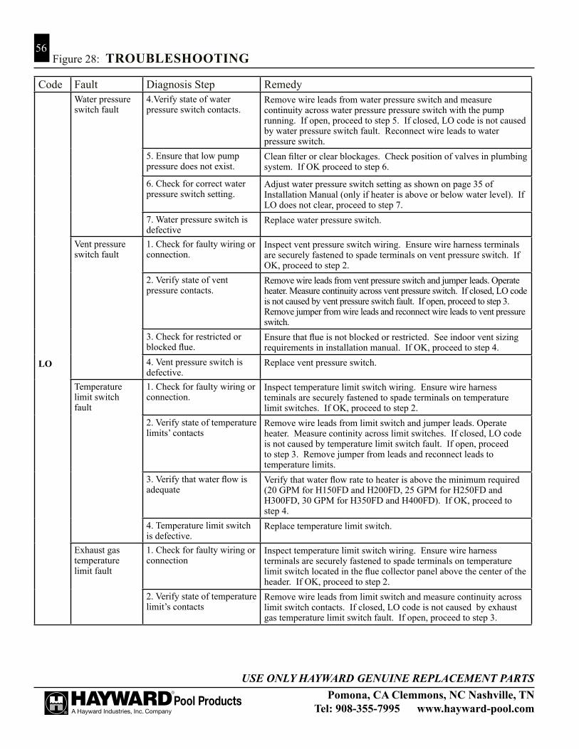
Pomona, CA Clemmons, NC Nashville, TNTel: 908-355-7995 www.hayward-pool.com
USE ONLY HAYWARD GENUINE REPLACEMENT PARTS
56
Code Fault Diagnosis Step Remedy
LO
Water pressure switch fault
4.Verify state of water pressure switch contacts.
Remove wire leads from water pressure switch and measure continuity across water pressure pressure switch with the pump running. If open, proceed to step 5. If closed, LO code is not caused by water pressure switch fault. Reconnect wire leads to water pressure switch.
5. Ensure that low pump pressure does not exist.
Clean filter or clear blockages. Check position of valves in plumbing system. If OK proceed to step 6.
6. Check for correct water pressure switch setting.
Adjust water pressure switch setting as shown on page 35 of Installation Manual (only if heater is above or below water level). If LO does not clear, proceed to step 7.
7. Water pressure switch is defective
Replace water pressure switch.
Vent pressure switch fault
1. Check for faulty wiring or connection.
Inspect vent pressure switch wiring. Ensure wire harness terminals are securely fastened to spade terminals on vent pressure switch. If OK, proceed to step 2.
2. Verify state of vent pressure contacts.
Remove wire leads from vent pressure switch and jumper leads. Operate heater. Measure continuity across vent pressure switch. If closed, LO code is not caused by vent pressure switch fault. If open, proceed to step 3. Remove jumper from wire leads and reconnect wire leads to vent pressure switch.
3. Check for restricted or blocked flue.
Ensure that flue is not blocked or restricted. See indoor vent sizing requirements in installation manual. If OK, proceed to step 4.
4. Vent pressure switch is defective.
Replace vent pressure switch.
Temperature limit switch fault
1. Check for faulty wiring or connection.
Inspect temperature limit switch wiring. Ensure wire harness teminals are securely fastened to spade terminals on temperature limit switches. If OK, proceed to step 2.
2. Verify state of temperature limits’ contacts
Remove wire leads from limit switch and jumper leads. Operate heater. Measure continity across limit switches. If closed, LO code is not caused by temperature limit switch fault. If open, proceed to step 3. Remove jumper from leads and reconnect leads to temperature limits.
3. Verify that water flow is adequate
Verify that water flow rate to heater is above the minimum required (20 GPM for H150FD and H200FD, 25 GPM for H250FD and H300FD, 30 GPM for H350FD and H400FD). If OK, proceed to step 4.
4. Temperature limit switch is defective.
Replace temperature limit switch.
Exhaust gas temperature limit fault
1. Check for faulty wiring or connection
Inspect temperature limit switch wiring. Ensure wire harness terminals are securely fastened to spade terminals on temperature limit switch located in the flue collector panel above the center of the header. If OK, proceed to step 2.
2. Verify state of temperature limit’s contacts
Remove wire leads from limit switch and measure continuity across limit switch contacts. If closed, LO code is not caused by exhaust gas temperature limit switch fault. If open, proceed to step 3.
Figure 28: TROUBLESHOOTING

Pomona, CA Clemmons, NC Nashville, TNTel: 908-355-7995 www.hayward-pool.com
USE ONLY HAYWARD GENUINE REPLACEMENT PARTS
57Figure 28: TROUBLESHOOTING
Code Fault Diagnosis Step Remedy
LO
Exhaust gas temperature limit fault
3. Heat exchanger has been damaged
Heat exchanger has been damaged. This is generally due to low water flow, poor water chemistry, or a combination of these and other factors. Rectify all issues with water flow through the heater and water chemistry and then replace the heat exchanger and exhaust gas temperature limit. Continuing to run the heater after this limit has tripped will cause damage to the entire unit and will not be covered by the warranty.
IF
Ignition Failure 1. Ensure gas supply shutoff valves are open.
Ensure that main gas shutoff installed adjacent to heater is open. Ensure that knob on gas valve inside unit is in ‘‘on’’ position. If OK, proceed to step 2.
2. Check for low gas supply pressure
Ensure inlet gas supply pressure is between the minimum and maximum values indicated on rating plate. If OK, proceed to step 3.
3. Check for faulty flame sense wiring or connection.
Inspect flame sense wiring. Ensure wire harness terminals are securely fastened to flame sense and to control module. If OK, proceed to step 4.
4. Check for faulty gas valve wiring or connection
Inspect gas valve wiring. Ensure wire harness terminals are securely fastened to spade terminals on gas valve. If OK, proceed to step 5.
5. Check for gas valve failure or gas valve relay failure.
1. Measure voltage across gas valve during trial for igintion. If 24VAC is present and gas valve does not open, gas valve is defective. Replace gas valve. 2. If 24VAC is not present, gas valve relay on control module is defective. Replace control module.
6. Check for blockages in gas orifices and burners
Inspect gas orifices for blockages which could prevent gas flow. Remove and inspect burners for blockages.
AC
Blower vacuum switch closed.
1. Check for defective blower on relay or control module.
Disconnect Blower plug fron Control Module. With heater off, measure continuity across pins 1 and 2 of receptacle on Control Module. If closed, control module relay is defective. Replace control module. If OK, proceed to step 2.
2. Vacuum switch is defective.
Replace blower vacuum switch.

Pomona, CA Clemmons, NC Nashville, TNTel: 908-355-7995 www.hayward-pool.com
USE ONLY HAYWARD GENUINE REPLACEMENT PARTS
58
Code Fault Diagnosis Step Remedy
AO
Blower vacuum switch open.
1. Check for faulty vacuum switch tubing
Check tubing and replace if necessary. If OK, proceed to step 2.
2. Check for faulty vacuum switch wiring or connection.
Inspect vacuum switch wiring. Ensure wire harness terminals are securely fastened to spade terminals on vacuum switch. If OK, proceed to step 3.
3. Check for faulty blower wiring or connection
Inspect blower wiring. Ensure plug on blower is securely fastened to control module. If OK, proceed to step 4.
4. Check for defective vacuum switch
Disconnect Blower plug from Control Module. Measure resistance across Blower windings. Winding resistance across lead should be in the following range; Red-to-White: 4 to 5 ohms. If measured values vary substantially from these values, Blower is defective. Replace. If OK, proceed to step 5.
5. Check for defective blower relay.
Disconnect Blower plug from Control Module. Place heater in Pool or Spa Mode. Lower set point temperature to generate call for heat. During pre-purge period, measure for 120VAC across pins 1 and 2. If 120VAC is not present, control module relay is defective. Replace control module. If OK, proceed to step 6
6. Vacuum switch is defective
Replace blower vacuum switch.
bO
Bypass Operation
1. Check to see if Control Module is in Bypass Operation
This is normal display when heater is being controlled by a remote thermostat. No service is required. If heater is not being controlled by remote thermostat, change setting by using the MODE key to put the heater into STANDBY. Press and hold the DOWN key and then press and hold the MODE key. Hold down both keys for 3 seconds until the indication ‘‘bO’’ is removed from the display.
Pomona, CA Clemmons, NC Nashville, TNTel: 908-355-7995 www.hayward-pool.com
USE ONLY HAYWARD GENUINE REPLACEMENT PARTS
59
LIMITED HEATER WARRANTy:
TERMS AND COVERAGE: We warrant our pool heater to be free from defects in workmanship and materials under normal use and
service. Pursuant to this warranty and subject to the Conditions and Exceptions indicated below: 1. We will replace (cost of freight, installation, cost of fuel, and service labor at user’s expense) with
the prevailing comparable model, or, at our option, repair any pool/spa heater that leaks under nor-mal use and service within one year from the date of original installation for all users.
2. In addition, we will replace (cost of freight, installation, cost of fuel, and service labor at user’s expense) or, at our option, repair any part or parts of the pool/spa heater which malfunctions under normal use and service within one year from the date of original installation for all users.
LIMITATION ON IMPLIED WARRANTIES: WE ARE NOT LIABLE FOR ANy CONSEQUENTIAL DAMAGES FOR BREACH OF ANy WRIT-
TEN OR IMPLIED WARRANTy OF THIS PRODUCT. Implied warranties, including the WARRANTy of MERCHANTABILITy and all other implied warranties that may arise from course of dealing or usage of trade imposed on the sale of this heater under laws of the state are limited in duration to the term of one (1) year for all products when products are NOT installed and serviced by a licensed and qualified pool equip-ment professional with all sufficient experience in pool equipment installation and maintenance and adhering to the requirements of the jurisdiction where the product is installed.
Warranty extends in duration to the term of (2) years for all non-ASME certified products ONLy when products are installed and serviced by a licensed and qualified pool equipment professional with sufficient experience in pool equipment installation and maintenance and adhering to the requirements of the jurisdic-tion where the product is installed. There are no warranties which extend beyond the description on the face hereof. We shall not in any event be held liable for any special, indirect or consequential damages.
EXPENSE OF DELIVERy AND INSTALLATION:Each pool heater or replacement part to be furnished under this warranty shall be furnished at our nearest
distribution center. We shall not pay, nor be responsible for shipping or delivery charges to the place of instal-lation, nor for labor charges or other costs of removal or installation. Every defective heater or part replaced under this warranty shall become our property, and as such, must be returned to our distribution center with transportation charges paid by the user. Any replacement pool heater furnished under this warranty shall re-main in warranty only for the unexpired portion of this warranty.
CONDITIONS AND EXCEPTIONS:This warranty applies only to the pool/spa at its original place of installation and only for the original
owner. It does not apply if the pool heater is installed in violation of any applicable code or ordinance, or is not installed, operated and maintained in accordance with our instructions, or is misused, damaged by ac-cident, weather, act of God, freezing, water void and/or excess pressure, altered or disconnected. It does not apply with respect to:
1. A heater not equipped with Certified C.S.A. limit controls or equivalent pressure relief valve. 2. A heater operated with settings in excess of, and/or with fuel not conforming to those shown on rat-
ing plate; 3. A heater on which the serial numbers have been altered, defaced, or removed. 4. Leaks arising from defective installation; 5. Production of noise, odors, or discolored (rusty, etc.) water;
HAyWARD POOL HEATER CERTIFICATE OF LIMITED WARRANTy

Pomona, CA Clemmons, NC Nashville, TNTel: 908-355-7995 www.hayward-pool.com
USE ONLY HAYWARD GENUINE REPLACEMENT PARTS
60
6. Leakage substantially contributed to by sediment, lime precipitate and/or higher than normal dis-solved solids (pH above 7.8) in the tank, copper tubes, or water ways;
7. Leakage caused substantially contributed to by corrosive elements in the atmosphere (such as the storage of chlorine or other chemicals);
8. Leakage caused substantially or contributed to by corrosive pool water in an acid condition (pH be-low 7.2);
9. Damage caused substantially or contributed to by an external source of energy; 10. A pool/spa heater is a water containing device. Leakage of water from this device can be expected
at some time due to malfunction or the limitations of the service life of various components. Do not install this product where such leakage can cause damage. MANUFACTURER IS NOT RESPON-SIBLE OR LIABLE FOR ANy COSTS INCURRED By SUCH DAMAGE.
IN NO CASE ARE WE TO BE HELD LIABLE FOR DAMAGETO SURROUNDING AREA OR PROPERTYCAUSED BY LEAKAGE OR MALFUNCTION.
HOW TO CLAIM UNDER THIS WARRANTy: The original owner, upon discovering the defect, must present the attached completed warranty claim card
with proof of purchase either to the dealer or notify Hayward in writing at the following address:
HAyWARD INDUSTRIES, INC.620 DIVISION ST.ELIZABETH, NJ 07207
Upon receipt of such notification we shall decide whether to repair such parts or replace any pool heater, reserving at all times the right to inspect in order to verify any claimed defect. We also reserve the right to have our representatives make any inspections, repairs, or to furnish replacements. This warranty is intended as a legally binding obligation of Hayward Industries, Inc., enforceable in the courts. This warranty may give you specific legal rights which may vary from state to state.
LIMITATION ON LIABILITy: All intended representations have been expressly set forth in this document. This warranty may not be
extended by oral or any other additional representations, written sales information, drawings, or other malfunc-tion, is strictly limited to repair or replacement of the defective heater or part, as provided herein and Hayward Industries, Inc. is not responsible hereunder for incidental or consequential or incidental costs or damages. The company neither assumes, nor authorizes any person or firm to assume for us, any further liability or obligation in connection with the sale, installation, use, maintenance, or existence of the heater. SAFETy WARNING: Pool heaters are heat producing appliances and to avoid damage or injury in the event of possible overheating of the outer jacket (1) no materials should be stored against the jacket and (2) care should be taken to avoid un-necessary contact (especially by children) with the jacket. When lighting a gas heater, the lighting instructions must be followed exactly to prevent “flashback” of excess gas in the heater. Electronic ignition heaters and electric heaters must have the power shut off when making adjustments to, servicing, or coming into contact with the heater. UNDER NO CIRCUMSTANCES SHOULD FLAMMABLE MATERIALS, SUCH AS GAS-OLINE OR PAINT THINNERS, BE USED OR STORED IN THE VICINITy OF THE HEATER OR IN ANy LOCATION FROM WHICH FUMES COULD REACH THE HEATER. For your comfort, enjoyment and safety, please read the enclosed operating instructions carefully.

Pomona, CA Clemmons, NC Nashville, TNTel: 908-355-7995 www.hayward-pool.com
USE ONLY HAYWARD GENUINE REPLACEMENT PARTS
61
32
41
30
42
27
26
22
21
23
29
Bronze Header Models (ASME) Plastic Header Models (Non-ASME)
18
20 19
2524
15
1716
11
7
6
9
10
41213
14
1
2
28
5
31
10
8
3
38
34
35
39
30
293733
36
27
32
40
SERVICE PARTS

Pomona, CA Clemmons, NC Nashville, TNTel: 908-355-7995 www.hayward-pool.com
USE ONLY HAYWARD GENUINE REPLACEMENT PARTS
62
ITEM PART NO. DESCRIPTION 1 FDXLJKT1150 JACKET TOP - H150FD FDXLJKT1200 JACKET TOP - H200FD FDXLJKT1250 JACKET TOP - H250FD FDXLJKT1300 JACKET TOP - H300FD FDXLJKT1350 JACKET TOP - H350FD FDXLJKT1400 JACKET TOP - H400FD FDXLJKT1500 JACKET TOP - H500FD FDXLJKT1250A JACKET TOP, GRAy, ASME - H250FD FDXLJKT1400A JACKET TOP, GRAy, ASME - H400FD FDXLJKT1500A JACKET TOP, GRAy, ASME - H500FD 2 FDXLTFC1150 TOP FLUE COVER - H150FD FDXLTFC1200 TOP FLUE COVER - H200FD FDXLTFC1250 TOP FLUE COVER - H250FD FDXLTFC1300 TOP FLUE COVER - H300FD FDXLTFC1350 TOP FLUE COVER - H350FD FDXLTFC1400 TOP FLUE COVER - H400FD FDXLTFC1500 TOP FLUE COVER - H500FD FDXLTFC1250A TOP FLUE COVER, GRAy, ASME - H250FD FDXLTFC1400A TOP FLUE COVER, GRAy, ASME - H400FD FDXLTFC1500A FRONT ACCESS DOOR, GRAy, ASME - H500FD 3 FDXLFAD1150 FRONT ACCESS DOOR ASSy - H150FD FDXLFAD1200 FRONT ACCESS DOOR ASSy - H200FD FDXLFAD1250 FRONT ACCESS DOOR ASSy - H250FD FDXLFAD1300 FRONT ACCESS DOOR ASSy - H300FD FDXLFAD1350 FRONT ACCESS DOOR ASSy - H350FD FDXLFAD1400 FRONT ACCESS DOOR ASSy - H400FD FDXLFAD1500 FRONT ACCESS DOOR ASSy - H500FD FDXLFAD1250A FRONT ACCESS DOOR ASSy, GRAy, ASME - H250FD FDXLFAD1400A FRONT ACCESS DOOR, GRAy ASME - H400FD FDXLFAD1500A FRONT ACCESS DOOR ASSy, GRAy ASME H500FD 4 FDXLRAD1150 REAR ACCESS DOOR ASSy - H150FD FDXLRAD1200 REAR ACCESS DOOR ASSy - H200FD FDXLRAD1250 REAR ACCESS DOOR ASSy - H250FD FDXLRAD1300 REAR ACCESS DOOR ASSy - H300FD FDXLRAD1350 REAR ACCESS DOOR ASSy - H350FD FDXLRAD1400 REAR ACCESS DOOR ASSy - H400FD FDXLRAD1500 REAR ACCESS DOOR ASSy - H500FD FDXLRAD1250A REAR ACCESS DOOR ASSy, GRAy, ASME - H250FD FDXLRAD1400A REAR ACCESS DOOR ASSy, GRAy, ASME - H400FD FDXLRAD1500A REAR ACCESS DOOR ASSy - H500FD 5 FDXLTFP1151 TOP FRONT PANEL - H150FD FDXLTFP1201 TOP FRONT PANEL - H200FD FDXLTFP1251 TOP FRONT PANEL - H250FD FDXLTFP1301 TOP FRONT PANEL - H300FD FDXLTFP1351 TOP FRONT PANEL - H350FD FDXLTFP1401 TOP FRONT PANEL - H400FD
SERVICE PARTS

Pomona, CA Clemmons, NC Nashville, TNTel: 908-355-7995 www.hayward-pool.com
USE ONLY HAYWARD GENUINE REPLACEMENT PARTS
63
ITEM PART NO. DESCRIPTION FDXLTFP1501 TOP FRONT PANEL - H500FD FDXLTFP1251A TOP FRONT PANEL, GRAy, ASME - H250FD FDXLTFP1401A TOP FRONT PANEL, GRAy, ASME - H400FD FDXLTFP1501A TOP FRONT PANEL - H500FD 6 FDXLUEC1930 UPPER END CAP 7 FDXLLEC1930 LOWER END CAP 8 FDXLLTP1930 LEFT TRIM PANEL 9 FDXLRTP1930 RIGHT TRIM PANEL 10 FDXLPLC1930 JUNCTION BOX COVER, POLyMER, LEFT FDXLPRC1930 JUNCTION BOX COVER, POLyMER, RIGHT 11 FDXLPBL1930 BASE LEG 12 FDXLFCS1931 FLUE COLLECTOR SIDE PANEL W/ TEMPERATURE LIMIT 13 FDXLRGK1151 RAIN GUARD ASSEMBLy - 150K BTU HEATER FDXLRGK1201 RAIN GUARD ASSEMBLy - 200K BTU HEATER FDXLRGK1251 RAIN GUARD ASSEMBLy - 250K BTU HEATER FDXLRGK1301 RAIN GUARD ASSEMBLy - 300K BTU HEATER FDXLRGK1351 RAIN GUARD ASSEMBLy - 350K BTU HEATER FDXLRGK1401 RAIN GUARD ASSEMBLy - 400K BTU HEATER FDXLRGK1500 RAIN GUARD ASSEMBLy - 500K BTU HEATER 14 FDXLHBP1150 HEAT BARRIER PANEL - 150K BTU HEATER FDXLHBP1200 HEAT BARRIER PANEL - 200K BTU HEATER FDXLHBP1250 HEAT BARRIER PANEL - 250K BTU HEATER FDXLHBP1300 HEAT BARRIER PANEL - 300K BTU HEATER FDXLHBP1350 HEAT BARRIER PANEL - 350K BTU HEATER FDXLHBP1400 HEAT BARRIER PANEL - 400K BTU HEATER FDXLHBP1500 HEAT BARRIER PANEL - 500K BTU HEATER 15 FDXLBBN1150 BLOWER INLET BAFFLE - 150K BTU HEATER FDXLBBN1200 BLOWER INLET BAFFLE - 200K BTU HEATER FDXLBBN1250 BLOWER INLET BAFFLE - 250K BTU HEATER FDXLBBN1300 BLOWER INLET BAFFLE - 300K BTU HEATER FDXLBBN1350 BLOWER INLET BAFFLE - 350K BTU HEATER FDXLBBN1400 BLOWER INLET BAFFLE - 400K BTU HEATER FDXLBBN1500 BLOWER INLET BAFFLE - 500K BTU HEATER 16 FDXLIAC1930 IGNITER ACCESS COVER 17 FDXLGSV0001 GAS VALVE, NATURAL FDXLGSV0002 GAS VALVE, PROPANE FDXLGSV1500N GAS VALVE, NATURAL - 500K BTU HEATER FDXLGSV1500P GAS VALVE, PROPANE - 500K BTU HEATER 18 FDXLBON1930 BURNER ORIFICE KIT, NATURAL FDXLBOP1930 BURNER ORIFICE KIT, PROPANE FDXLBON1500 BURNER ORIFICE KIT, NATURAL - H500FD FDXLBOP1500 BURNER ORIFICE KIT, PROPANE - H500FD 19 FDXLMAN1150 GAS MANIFOLD - 150K BTU HEATER FDXLMAN1200 GAS MANIFOLD - 200K BTU HEATER FDXLMAN1250 GAS MANIFOLD - 250K BTU HEATER FDXLMAN1300 GAS MANIFOLD - 300K BTU HEATER
SERVICE PARTS

Pomona, CA Clemmons, NC Nashville, TNTel: 908-355-7995 www.hayward-pool.com
USE ONLY HAYWARD GENUINE REPLACEMENT PARTS
64
FDXLMAN1350 GAS MANIFOLD - 350K BTU HEATER FDXLMAN1400 GAS MANIFOLD - 400K BTU HEATER FDXLMAN1500 GAS MANIFOLD - 500K BTU HEATER FDXLGCK1150NP CONVERSION KIT, NA TO LP, QUICK-CHANGE - 150K BTU HEATER FDXLGCK1150PN CONVERSION KIT, LP TO NA, QUICK-CHANGE - 150K BTU HEATER FDXLGCK1200NP CONVERSION KIT, NA TO LP, QUICK-CHANGE - 200K BTU HEATER FDXLGCK1200PN CONVERSION KIT, LP TO NA, QUICK-CHANGE - 200K BTU HEATER FDXLGCK1250NP CONVERSION KIT, NA TO LP, QUICK-CHANGE - 250K BTU HEATER FDXLGCK1250PN CONVERSION KIT, LP TO NA, QUICK-CHANGE - 250K BTU HEATER FDXLGCK1300NP CONVERSION KIT, NA TO LP, QUICK-CHANGE - 300K BTU HEATER FDXLGCK1300PN CONVERSION KIT, LP TO NA, QUICK-CHANGE - 300K BTU HEATER FDXLGCK1350NP CONVERSION KIT, NA TO LP, QUICK-CHANGE - 350K BTU HEATER FDXLGCK1350PN CONVERSION KIT, LP TO NA, QUICK-CHANGE - 350K BTU HEATER FDXLGCK1400NP CONVERSION KIT, NA TO LP, QUICK-CHANGE - 400K BTU HEATER FDXLGCK1400PN CONVERSION KIT, LP TO NA, QUICK-CHANGE - 400K BTU HEATER FDXLGCK1500NP CONVERSION KIT, NA TO LP, QUICK-CHANGE - 500K BTU HEATER FDXLGCK1500PN CONVERSION KIT, LP TO NA, QUICK-CHANGE - 500K BTU HEATER 20 FDXLBWR1930 COMBUSTION BLOWER FDXLBWR1500 COMBUSTION BLOWER - H500FD 21 FDXLBVS1930 BLOWER VACUUM SWITCH 22 FDXLICB1930 INTEGRATED CONTROL BOARD 23 FDXLFWP1930 FIELD WIRING PANEL 24 FDXLIGN1930 IGNITOR 25 IDXLFLS1930 FLAME SENSOR 26 IDXL2TRF1930 TRANSFORMER 27 FDXLWPS1930 WATER PRESSURE SWITCH 28 IDXL2DB1930 DISPLAy BOARD ONLy FDXLBKP1930 BEZEL & KEyPAD ASSEMBLy FDXLBKP1931 BEZEL & KEyPAD ASSEMBLy, BLUE, ASME FDXLGSK1932 GASKET, BEZEL/TOP 29 FDXLHLI1930 HIGH LIMIT KIT 30 FDXLTER1930 THERMISTOR 31 FDXLGSK1934 GASKET, CC FRONT/AIR BOX - ALL MODELS 32 FDXLHXA1150 HEAT EXCHANGER ASSy - 150K BTU HEATER FDXLHXA1200 HEAT EXCHANGER ASSy - 200K BTU HEATER FDXLHXA1250 HEAT EXCHANGER ASSy - 250K BTU HEATER FDXLHXA1300 HEAT EXCHANGER ASSy - 300K BTU HEATER FDXLHXA1350 HEAT EXCHANGER ASSy - 350K BTU HEATER FDXLHXA1400 HEAT EXCHANGER ASSy - 400K BTU HEATER FDXLHXA1500 HEAT EXCHANGER ASSy - 500K BTU HEATER FDXLHXA1250A HEAT EXCHANGER ASSy, ASME - 250K BTU COMMERCIAL HEATER FDXLHXA1400A HEAT EXCHANGER ASSy, ASME - 400K BTU COMMERCIAL HEATER FDXLHXA1500A HEAT EXCHANGER ASSy, ASME - 500K BTU COMMERCIAL HEATER 33 FDXLFHD1930 INLET/OUTLET HEADER ONLy FDXLFHA1930 INLET/OUTLET HEADER ASSy 34 FDXLHDW1930 HEADER HARDWARE KIT
ITEM PART NO. DESCRIPTION
SERVICE PARTS

Pomona, CA Clemmons, NC Nashville, TNTel: 908-355-7995 www.hayward-pool.com
USE ONLY HAYWARD GENUINE REPLACEMENT PARTS
65
35 FDXLHMB1930 HEADER MOUNTING BASE KIT 36 FDXLBKP1930 ByPASS CARTRIDGE KIT 37 CHXPLG1930 3/4” BRASS PLUG 38 FDXLCRN1930 HEADER CARTRIDGE RETAINING NUT 39 SPX4000FG DRAIN PLUG WITH GASKET 40 FDXLPRM1930 RETURN MANIFOLD REPLACEMENT KIT 41 FDXLDRV1930A DRAIN VALVE, ASME 42 CHXRLV1930 PRESSURE RELIEF VALVE NOT SHOWN: --- FDXLGSK1930 GASKET KIT, AIR SIDE - ALL MODELS Includes: GASKET, BLOWER MOUNTING GASKET, IGNITER COVER GASKET, COVER/AIR BOX FRONT - ALL MODELS GASKET, MANIFOLD/AIR BOX - ALL MODELS --- FDXLGSK1931 GASKET KIT, EXHAUST SIDE - ALL MODELS Includes: GASKET, FLUE COLLECTOR SIDE GASKET, RAIN GUARD SIDE GASKET, RAIN GUARD BOTTOM SIDE GASKET, FLUE COLLECTOR TOP - ALL MODELS GASKET, RAIN GUARD FRONT & REAR - ALL MODELS GASKET, RAIN GUARD BOTTOM FRONT & REAR - ALL MODELS --- FDXLGSK1933 INSULATION, RETURN SIDE TUBE SHEET --- FDXLBRN1930 BURNER --- FDXLFOR1930 HEADER O-RING KIT --- FDXLEGL1930 EXHAUST GAS TEMPERATURE LIMIT (ONE-USE) --- FDXLWHA1930 WIRING HARNESS KIT, COMPLETE --- FDXLVSJ1930 VOLTAGE SELECTOR JUMPER --- FDXLFSK1930 FUSE SERVICE KIT --- FDXLFSKF30 FUSE KIT, 3.0A, FOR FIELD WIRING PANEL (QTy 10) --- FDXLFSKC30 FUSE KIT, 3.0A, FOR INTEGRATED CONTROL BOARD (QTy 10) --- SPX3200UNKIT UNION KIT (INCLUDES FITTINGS, UNION NUTS, GASKETS) --- FDXLUNK1930A ASME UNION FLANGE KIT (INCL. FITTINGS, BOLTS, GASKETS) --- FDXLTDK1930 TIE-DOWN KIT --- FDXLDRV1930A DRAIN VALVE, ASME --- UHXNEGVT11501 INDOOR VENT ADAPTER KIT, NEG-PRESS (VERTICAL) - 150K BTU HEATER --- UHXNEGVT12001 INDOOR VENT ADAPTER KIT, NEG-PRESS (VERTICAL) - 200K BTU HEATER --- UHXNEGVT12501 INDOOR VENT ADAPTER KIT, NEG-PRESS (VERTICAL) - 250K BTU HEATER --- UHXNEGVT13001 INDOOR VENT ADAPTER KIT, NEG-PRESS (VERTICAL) - 300K BTU HEATER --- UHXNEGVT13501 INDOOR VENT ADAPTER KIT, NEG-PRESS (VERTICAL) - 350K BTU HEATER --- UHXNEGVT14001 INDOOR VENT ADAPTER KIT, NEG-PRESS (VERTICAL) - 400K BTU HEATER --- UHXNEGVT15001 INDOOR VENT ADAPTER KIT, NEG-PRESS (VERTICAL) - 500K BTU HEATER --- UHXPOSHZ11501 INDOOR VENT ADAPTER KIT, POS-PRESS (HORIZONTAL) - 150K BTU HEATER --- UHXPOSHZ12001 INDOOR VENT ADAPTER KIT, POS-PRESS (HORIZONTAL) - 200K BTU HEATER --- UHXPOSHZ12501 INDOOR VENT ADAPTER KIT, POS-PRESS (HORIZONTAL), 6” DIA. - 250K BTU HEATER
ITEM PART NO. DESCRIPTION
SERVICE PARTS

Pomona, CA Clemmons, NC Nashville, TNTel: 908-355-7995 www.hayward-pool.com
USE ONLY HAYWARD GENUINE REPLACEMENT PARTS
66
ITEM PART NO. DESCRIPTION NOT SHOWN (CONTINUED) --- UHXPOSHZ12502 INDOOR VENT ADAPTER KIT, POS-PRESS (HORIZONTAL), 4” DIA. - 250K BTU HEATER --- UHXPOSHZ13001 INDOOR VENT ADAPTER KIT, POS-PRESS (HORIZONTAL) - 300K BTU HEATER --- UHXPOSHZ13501 INDOOR VENT ADAPTER KIT, POS-PRESS (HORIZONTAL) - 350K BTU HEATER --- UHXPOSHZ14001 INDOOR VENT ADAPTER KIT, POS-PRESS (HORIZONTAL), 8” DIA. - 400K BTU HEATER --- UHXPOSHZ14002 INDOOR VENT ADAPTER KIT, POS-PRESS (HORIZONTAL), 6” DIA. - 400K BTU HEATER --- UHXPOSHZ15002 INDOOR VENT ADAPTER KIT, POS-PRESS (HORIZONTAL) - 500K BTU HEATER --- UHXHD6ETERM HEATFAB STAINLESS VENT KIT, 6” HORIZONTAL ELBOW TERMINAL --- UHXHD6STERM HEATFAB STAINLESS VENT KIT, 6” HORIZONTAL STRAIGHT TERMINAL --- UHXHD6ELBOW HEATFAB STAINLESS VENT KIT, 6” 90-DEGREE ELBOW --- UHXHD6PIPE18 HEATFAB STAINLESS VENT KIT, 6” VENT PIPE, 18” LONG --- UHXHD6PIPE24 HEATFAB STAINLESS VENT KIT, 6” VENT PIPE, 24” LONG --- UHXHD6PIPE36 HEATFAB STAINLESS VENT KIT, 6” VENT PIPE, 36” LONG --- UHXHD8STERM HEATFAB STAINLESS VENT KIT, 8” HORIZONTAL STRAIGHT TERMINAL --- UHXHD8ELBOW HEATFAB STAINLESS VENT KIT, 8” 90-DEGREE ELBOW --- UHXHD8PIPE18 HEATFAB STAINLESS VENT KIT, 8” VENT PIPE, 18” LONG --- UHXHD8PIPE24 HEATFAB STAINLESS VENT KIT, 8” VENT PIPE, 24” LONG --- UHXHD8PIPE36 HEATFAB STAINLESS VENT KIT, 8” VENT PIPE, 36” LONG --- FDXLCNK0001 GAS CONVERSION KIT, NA TO LP --- FDXLCNK0002 GAS CONVERSION KIT, LP TO NA --- FDXLCNK0003 GAS CONVERSION KIT, NA TO LP - H500FD --- FDXLCNK0004 GAS CONVERSION KIT, LP TO NA - H500FD --- FDXLHAK1930 CONVERSION KIT, HIGH ALTITUDE, 2,000-10,100 FT --- FDXLVPS1930 VENT PRESSURE SWITCH, OUTDOOR AND INDOOR, 0-2,000 FT --- FDXLVPS1931 VENT PRESSURE SWITCH, INDOOR, 2,000-10,100 FT
SERVICE PARTS
Hayward Pool Products, Inc.620 Division St.Elizabeth, NJ 07207
Hayward Pool Products, Inc.2875 Pomona BoulevardPomona, CA 91768
Hayward Pool Products, Inc.2880 Plymouth DriveOakville, Ontario L6H 5R4
© 2016 Hayward Industris, Inc. Printed in U.S.A.

Pomona, CA Clemmons, NC Nashville, TNTel: 908-355-7995 www.hayward-pool.com
USE ONLY HAYWARD GENUINE REPLACEMENT PARTS
67SPECIFICATIONS
UNIT RATED CAPACITy
Model Natural Gas Propane Gas H150FD 150,000 Btu/hr 150,000 Btu/hr H200FD 199,000 Btu/hr 199,000 Btu/hr H250FD 250,000 Btu/hr 250,000 Btu/hr H300FD 300,000 Btu/hr 300,000 Btu/hr H350FD 350,000 Btu/hr 350,000 Btu/hr H400FD 399,000 Btu/hr 399,000 Btu/hr H500FD 500,000 Btu/hr 500,000 Btu/hr
GAS PRESSURE
Fuel Natural Gas Propane Gas Manifold 1.8” - 2.0” w.c. 6.8” - 7.0” w.c. Inlet, Minimum 4.5” w.c. 10.0” w.c. Inlet Maximum 10.5” w.c. 13.0” w.c.
ORIFICE SIzES
Models Natural Gas Propane Gas H150FD - H400FD #25 #43 H500FD #22 2.30 mm
WATER FLOW REQUIREMENTS
Model Minimum Maximum H150FD 20 125 H200FD 20 125 H250FD 25 125 H300FD 25 125 H350FD 30 125 H400FD 30 125 H500FD 40 125